® U.S. Registered Trademark
Copyright © 2001 Honeywell • • All Rights Reserved
INSTALLATION INSTRUCTIONS
69- 1463- 2
C7835A1009 Discharge Air
Temperature Sensor
APPLICATION
The C7835A1009 Discharge Air Temperature Sensor
(DATS) is a duct-mounted temperature probe that
provides capacity control of heating and cooling
equipment. It is used only with Honeywell networked
zoning. Mounted in the supply air duct, the DATS senses
the delivered air temperature and cuts off the heating or
cooling when the delivered air temperature goes above
or below normal operating limits. The heating and cooling
limits are field-adjustable.The DATS also compares the
discharge air temperature to the room temperature and,
if out of tolerance, a heating or cooling alert is issued. In
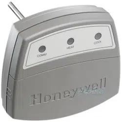
normal operation, the heat and cool lights are off, and the
COM light blinks periodically with activity on the
Enviracom bus.
When either limit setting is reached, the heating or
cooling shuts off, and the LEDs operate according to
Table 1. The call still exists and heated or cooled air is
still being supplied to the calling zones. Once the
delivered air temperature drops ten degrees for heating,
or rises ten degrees for cooling, the heating or cooling
equipment is brought back on. The ten degree differential
provides adequate minimum time-off to avoid damaging
the equipment.
NOTE: When using 50 Hz power, cut Jumper W1.
The location of the DATS is critical; it should not be
placed in line-of-sight of the heat exchanger or cooling
coil because the DATS could activate prematurely. It
should also be located before the bypass damper, when
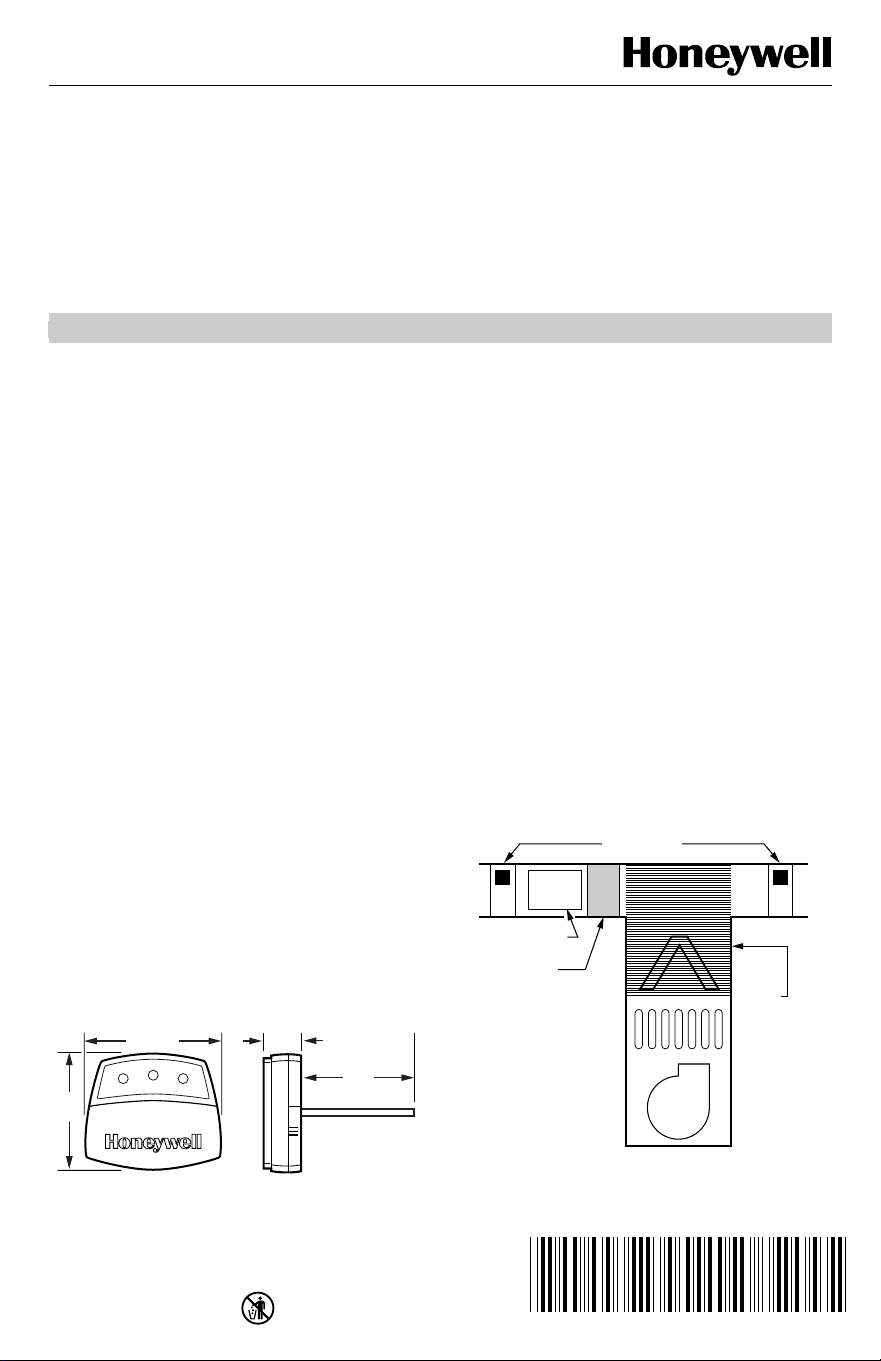
applicable. See Fig. 1 for dimensions.
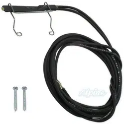
The DATS requires only three wires. Normal 18-22
gauge thermostat wire is used.
Fig. 1. C7835A dimensions in in. (mm).
INSTALLATION
When Installing this Product...
1.
Read these instructions carefully. Failure to follow
them could damage the product or cause a hazard-
ous condition.
2.
Check the ratings given in the instructions and on
the product to make sure the product is suitable for
your application.
3.
Installer must be a trained, experienced service
technician.
4.
After completing installation, use these instructions
to check out the product operation.
IMPORTANT
Do not locate the DATS probe in a duct near the
heat exchanger or strip heat, which can cause
false temperature readings.
1.
Locate the DATS on the supply trunk between the
bypass damper and the evaporator coil and/or heat
exchanger. If a bypass damper is not used, locate
the DATS between the zone dampers and the
evaporator coil and/or heat exchanger. See Fig. 2.
Fig. 2. DATS mounting location.
M19008
4-1/8 (102)
3-7/8
(77)
3-3/4
(77)
1-1/4
(25)
ZONE DAMPERS
BY PASS DAMPER
PLACE SENSOR
INTHIS AREA.
DO NOT
PLACE
SENSOR IN
THIS AREA.
M14877
EVAPORATOR COIL
HEAT EXCHANGER
BLOWER
C7835A1009 DISCHARGE AIR TEMPERATURE SENSOR
69-1463-2 2
2.
Drill a 5/16 in. hole in the duct at the location
selected for the sensor.
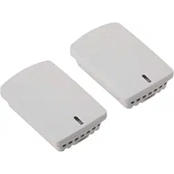
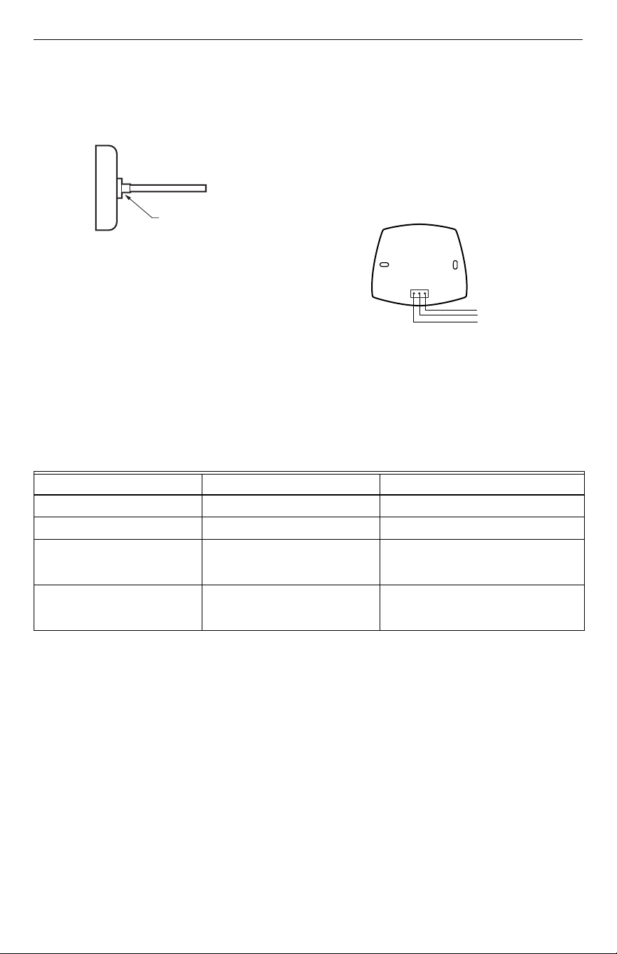
NOTE: Be sure the shoulder washer is inserted, see
Fig. 3, and fits tightly into the hole.
Fig. 3. Shoulder washer inserted on DATS.
3.
Remove the cover from the DATS case and insert
the probe into the hole drilled in step 2.
4.
Secure the DATS to the side of the duct, through
the two mounting holes in the back of the case,
with the screws supplied.
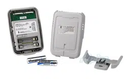
5.
Connect the three DATS terminals, see Fig. 4,
using standard thermostat wire, to any convenient
Enviracom 1,2, and 3 terminal connection.
Observe that the red heating and green cooling
lights come on momentarily.
6.
Adjust the MAX Temp dial on the DATS to the
appropriate high-limit setting. This can be set
between 110°F and 160° F (43°C and 71°C). Note
that settings between the lines are approximate
settings. The cooling low limit is adjustable
between 40°F (4°C) and 48°F (9°C) based on the
jumper position.
7.
Replace the cover on the DATS case.
Fig. 4. DATS wiring to Enviracom™ bus.
TROUBLESHOOTING
a
Heating or cooling system alerts can be cleared by cycling power, switching modes from heat to cool or vice versa, or
automatically when the equipment begins to operate correctly.
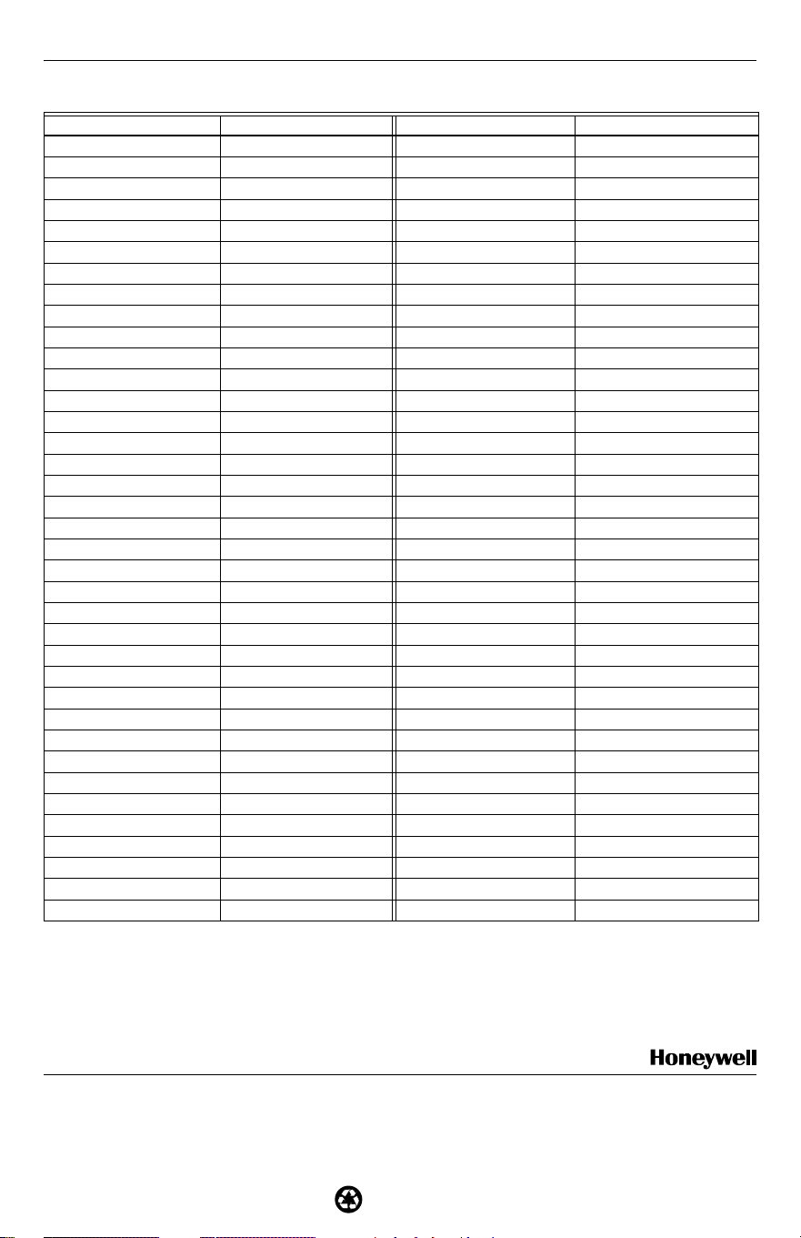
See Table 2 for resistance reading for each temperature
to determine if the DATS is reading the correct
temperature. To obtain a correct resistance
measurement, remove the sensor probe P1 connector
from the circuit board. Measure resistance across the
two sensor wires.
SHOULDER
WASHER
M19058
ENVIRACOM
BUS
C7835A WITH
COVER REMOVED
1
1
2
3
23
M14927
Table 1. LED Operation.
When DATS LED is... It means... It is corrected when...
Continuously red in heating. Heating limit was exceeded. Duct air temperature falls 10°F.
Continuously green in cooling. Cooling limit was exceeded. Duct air temperature rises 10°F.
Flashing red.
Heating system alert.
a
Discharge air is within 10°F of room
temperature continuously in heating
mode.
Flashing green.
Cooling system alert.
a
Discharge air is within 8°F of room
temperature continuously in cooling
mode.

C7835A1009 DISCHARGE AIR TEMPERATURE SENSOR
3 69-1463-2
Table 2. DATS Resistance Cross Reference
a
.
Temperature (°F) Resistance Temperature (°F) Resistance
32 33630 117 3915
33 32668 118 3830
34 31737 119 3747
35 30835 120 3666
36 29962 121 3587
37 29117 122 3510
38 28298 123 3435
39 27505 124 3362
40 26737 125 3290
41 25993 126 3221
42 25272 127 3153
43 24573 128 3086
44 23896 129 3021
45 23240 130 2958
46 22604 131 2896
47 21988 132 2836
48 21390 133 2777
49 20810 134 2720
50 20248 135 2664
51 19703 136 2609
52 19175 137 2555
53 18662 138 2503
54 18165 139 2452
55 17683 140 2402
56 17215 141 2353
57 16761 142 2306
58 16320 143 2259
59 15892 144 2214
60 15477 145 2170
61 15074 146 2126
62 14683 147 2084
63 14303 148 2043
64 13934 149 2002
65 13576 150 1963
66 13229 151 1924
67 12891 152 1886
68 12563 153 1849
69 12244 154 1813
70 11935 155 1778
71 11634 156 1744
72 11342 157 1710
73 11058 158 1677
74 10782 159 1645
75 10514 160 1613
76 10253 161 1582
77 10000 162 1552
78 9754 163 1523
79 9514 164 1494
69-1463-2 G.H. Rev. 9-01 www.honeywell.com/yourhome
C7835A1009 DISCHARGE AIR TEMPERATURE SENSOR
Printed in U.S.A. on recycled
paper containing at least 10%
post-consumer paper fibers.
Home and Building Control Home and Building Control
Honeywell Honeywell Limited-Honeywell Limitée
1985 Douglas Drive North 35 Dynamic Drive
Golden Valley, MN 55422 Scarborough, Ontario
M1V 4Z9
a
To obtain a correct resistance measurement, be sure the sensor probe is disconnected from the circuit board.
For Internet access: www.trolatemp.com
or
www.honeywell.com/yourhome/zoning/zoning_home.htm
For technical support, call 1-800-TAT-Temp (1-800-828-8367).
To download Zoning literature: http:hbctechlit.honeywell.com
80 9281 165 1466
81 9055 166 1438
82 8835 167 1411
83 8621 168 1385
84 8412 169 1359
85 8210 170 1334
86 8013 171 1309
87 7821 172 1285
88 7634 173 1261
89 7453 174 1238
90 7276 175 1215
91 7104 176 1193
92 6937 177 1171
93 6774 178 1150
94 6615 179 1129
95 6461 180 1108
96 6311 181 1088
97 6164 182 1069
98 6022 183 1050
99 5883 184 1031
100 5748 185 1012
101 5617 186 994
102 5488 187 977
103 5363 188 959
104 5242 189 943
105 5123 190 926
106 5008 191 910
107 4895 192 894
108 4786 193 878
109 4679 194 863
110 4575 195 848
111 4473 196 833
112 4374 197 819
113 4278 198 805
114 4183 199 791
115 4092 200 777
116 4002 — —
Table 2. DATS Resistance Cross Reference
a
. (Continued)
Temperature (°F) Resistance Temperature (°F) Resistance