
IP Surveillance
Installation Guide
VIVOTEK SD83XXE Speed Dome
Mounting Accessories
AM-116/117 Pendant Pipe
AM-118 Pendant Head
AM-221 Gooseneck
AM-231 Parapet Mount
AM-519 Pendant Adaptor
Rev. 1.1
Corresponding part numbers:
AM-116: 900014300G
AM-117: 900014400G
AM-118: 900014600G
AM-221: 900014800G
AM-231: 900015000G
AM-519: 900014900G
2
Compatible VIVOTEK Cameras
I
Speed Dome SD8364E, SD8363E, SD8333E, SD83x4E, SD83x6E, SD8362E
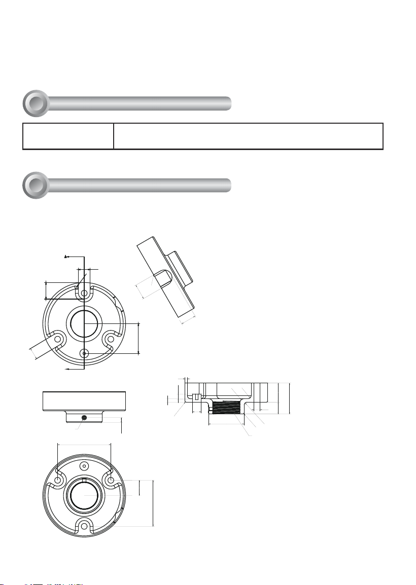
AM-118 Pendant Head
Revison History:
Rev. 1.0: Initial release
Rev. 1.1: Adding corresponding ordering part numbers and supported speed dome
models.
A
90
20
26.2
R1
26.2
77.94
25.98
28.04
20
R5
8.5
50
M6
R8
R5
60.3
R2
R5
2032.2
R2
10
4
52.2
10
6
15
1-1/2" PS11
Mechanical Drawings
II
3
English
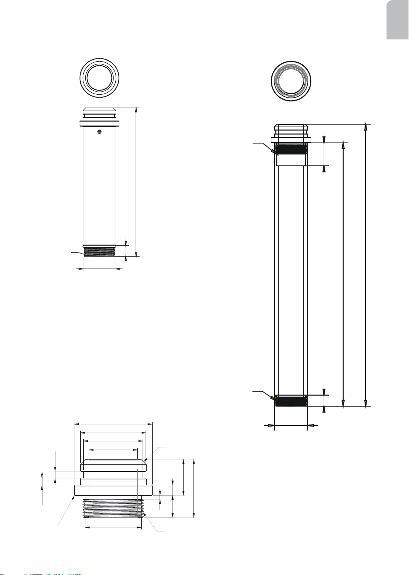
AM-116 20cm Pendant Pipe
n 50.8
17
228
1 1/2" PS11
AM-117 40cm Pendant Pipe
n 50.8
17
400
35
428
1 1/2" PS11
1 1/2" PS11
37,5
50,8
46
60,3
178
5,38
5,25
28
45
R0,5
3
43,6
1-1/2" PS11X17mm (L)
C4
AM-519 Pendant Adapter
(comes with the network camera)
4
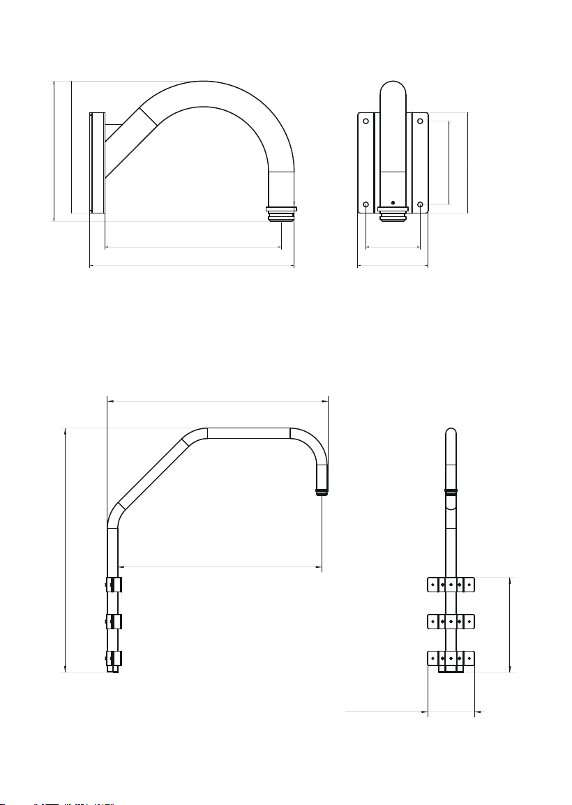
AM-221 Gooseneck
405.8
262.19
140
350107.8
165.5
200
278
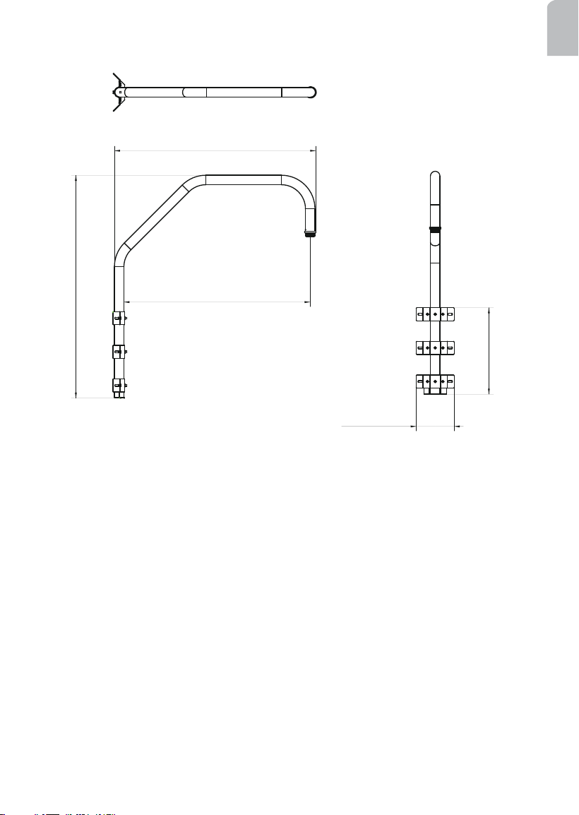
AM-231 Parapet Mount
1193
1077.95
997
463
228.15
5
English
AM-231 Parapet Corner Mount
1193
1077.95
997
202.95
463
6
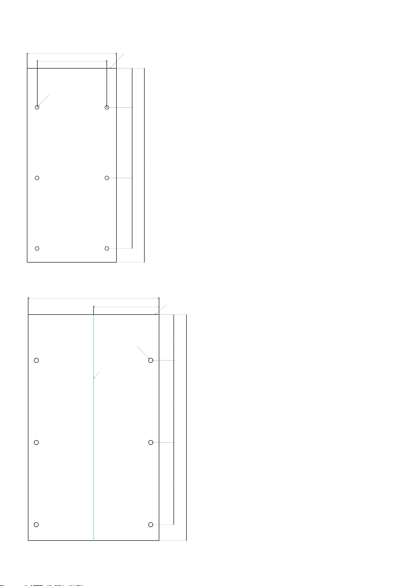
AM-231 Parapet Mount - Alignment Sticker
178.15
100180180
n 10
228.15
495
parapet top
AM-231 Corner Mount - Alignment Sticker
100180180
143.5
287
n 10
495
Fold Line
PARAPET TOP
7
English
Preparation before Installation
III
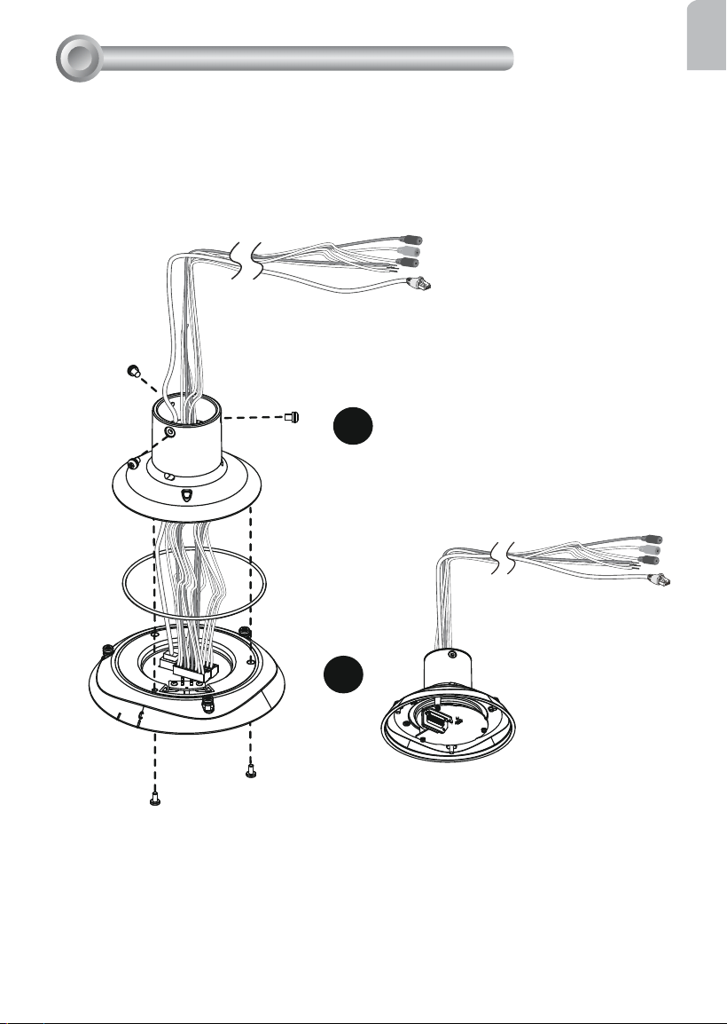
1
2
Connect Ethernet cable and IO wires (this may include the AC24V wires) to the interface
section of the camera, and then combine the interface section with the dome cap. Note
that you must route cables through the waterproof connector and the rubber seal plug, and
install them to the dome cap. Please refer to the Quick Installation Guide for details.
Cabling should be done before mounting the camera.
The top section will look like this.
8
Mounting & Cabling
IV
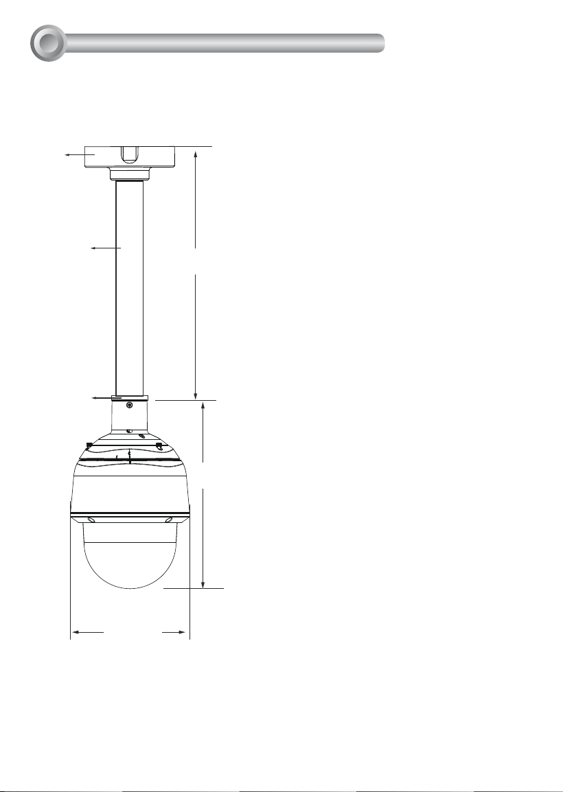
446.2 mm
AM-118
AM-117
AM-519
321.4 mm
204.8 mm
Shown below are the dimensions of a pendant mount conguration using the 40cm
pendant pipe.
IV-1. Pendant Pipe Mounting: AM-116/-117 & AM-118
9
English
AM-519
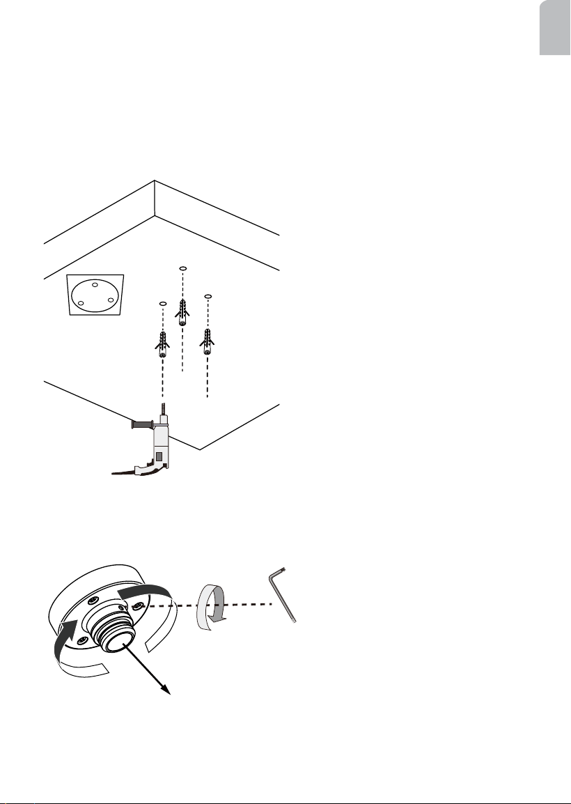
IV-1-1. Pendant Mount without Pendant Pipe: AM-118
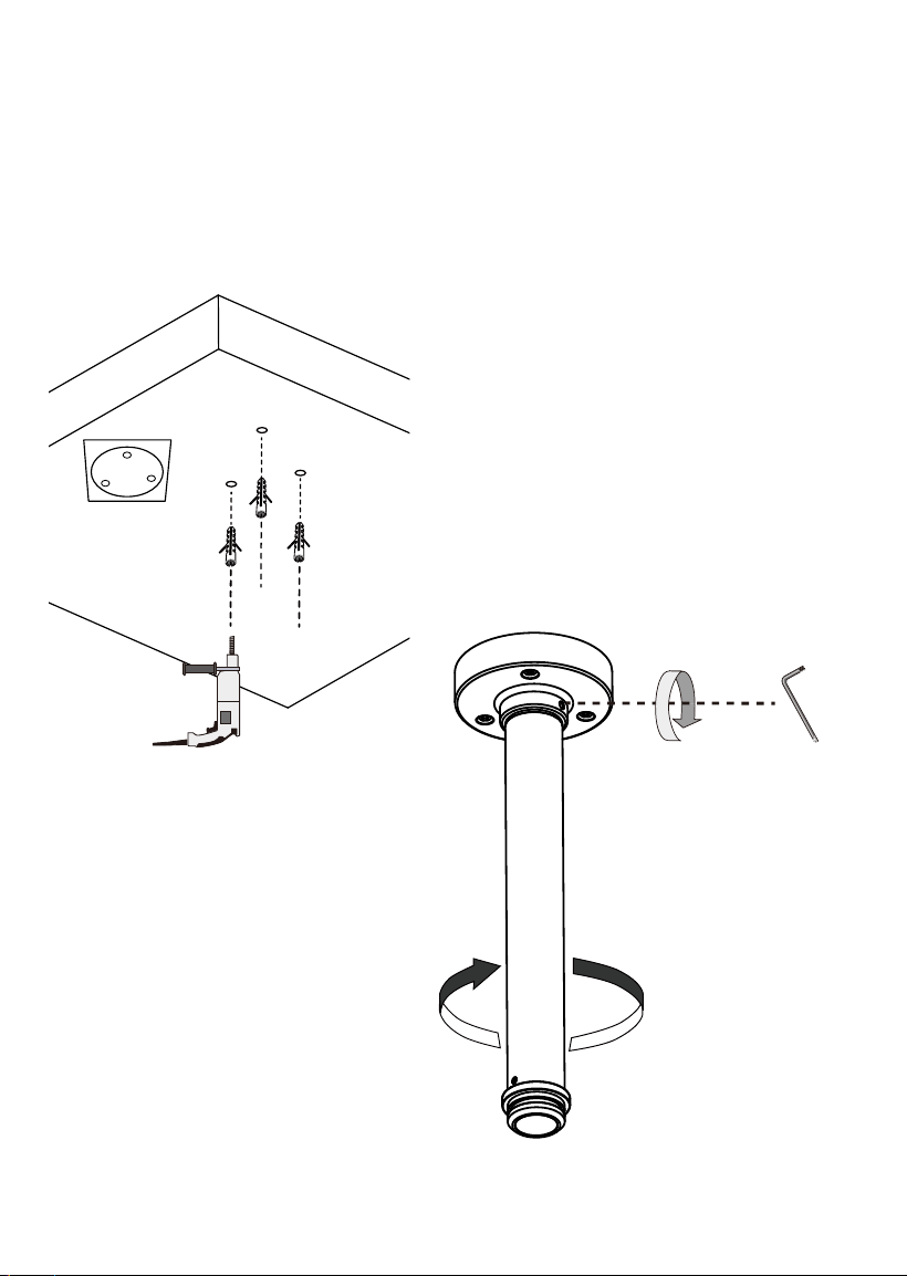
Below are the sample procedures using a pendant head and pendant pipe:
1. Determine a hard surface ceiling location, and use the alignment sticker to mark the
positions where holes will be drilled to secure the pendant head. Hammer the anchors
into the ceiling.
Note that mounting holes should be 10mm in diameter and 60mm deep. The included
screws are M6.2 x75mm.
2. Install a pendant adapter (AM-519) by turning it clockwise to the pendant head, and
secure the connection using an included 3mm hex wrench.
10
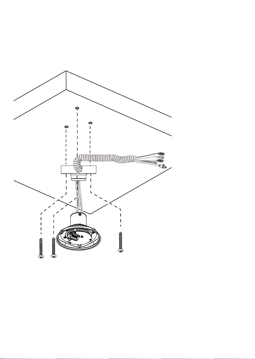
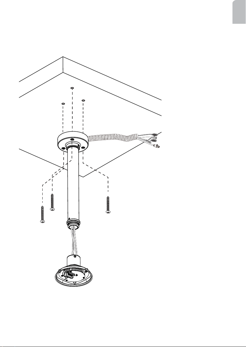
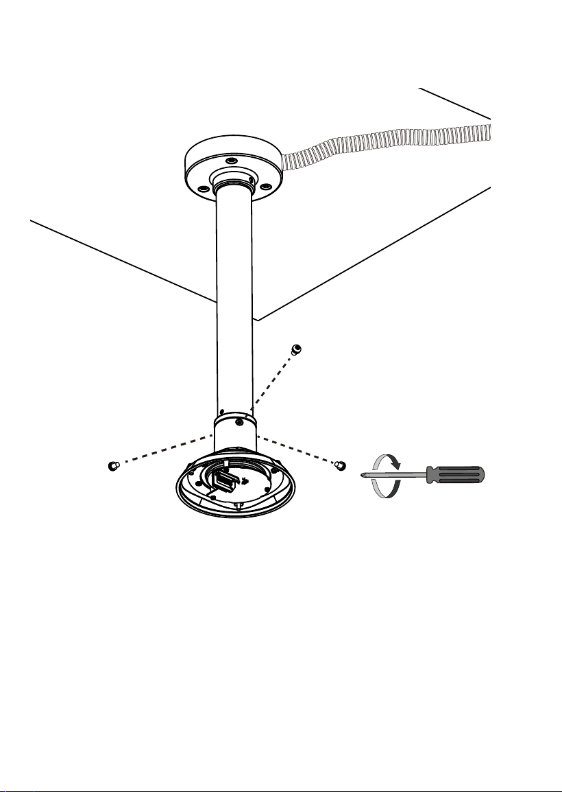
3. Route power lines and other wires through the pendant head. You may apply a 1 inch
conduit.
4. Secure the pendant head to ceiling by driving screws through its mounting holes.
Depending on the length of your cables, you may need the help from your colleague for
holding the camera top section.
Pendant Head
Camera top section
Cables
12
IV-1-2. Pendant Mount with Pendant Pipe: AM-116/AM-117 & AM-118
Below are the sample procedures using a pendant head and pendant pipe:
1. Determine a hard surface ceiling location, and use the alignment sticker to mark the
positions where holes will be drilled to secure the pendant head. Hammer the anchors
into the ceiling.
Note that mounting holes should be 10mm in diameter and 60mm deep. The included
screws are M6.2 x75mm.
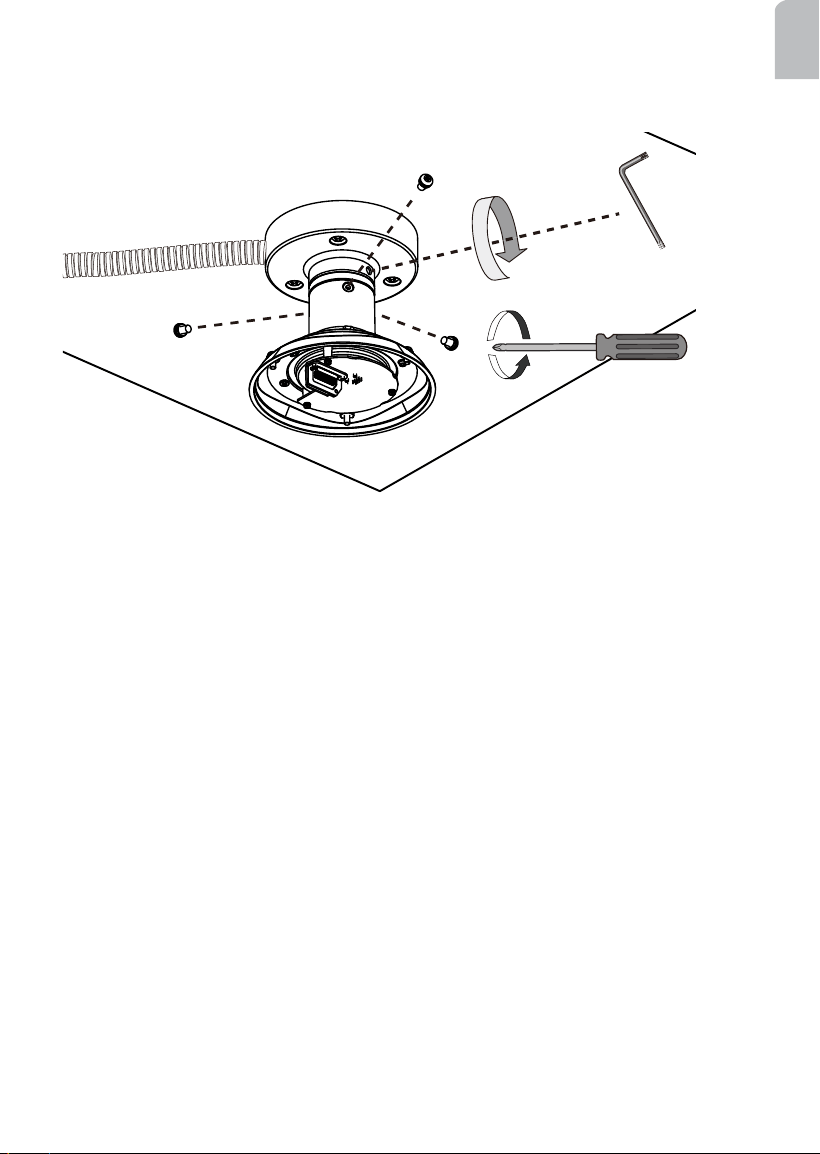
2. Install a 20cm or 40cm pendant pipe (AM-
116 or AM-117) by turning it clockwise
to the pendant head, and secure the
connection using an included 3mm hex
wrench.
13
English
3. Route power lines and other wires through the pendant head. You may apply a 1 inch
conduit.
4. Secure the pendant head to ceiling by driving screws through its mounting holes.
Depending on the length of your cables, you may need the help from your colleague for
holding the camera top section.
Pendant Head
Camera top section
Cables
15
English
IV-2. Gooseneck Mounting: AM-221
Below is a sample procedure using a gooseneck bracket:
1. Determine a hard surface wall location. Use the alignment sticker to mark the positions
where holes will be drilled for the gooseneck bracket.
1
2
3
5
HD WDR Pro
4
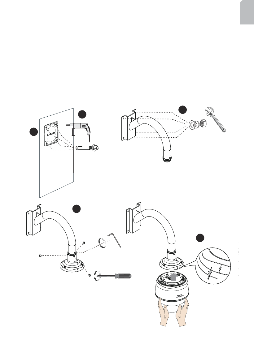
2. Drill 4 pilot holes (10mm in diameter and 5.5cm deep) into the wall, and then hammer in
threaded anchors. Note that you should hammer the anchors with hex nuts on them so
that the threaded poles will not be deformed! If preferred, drill another hole for routing
cables.
3. Secure the wall mount bracket to wall using 4 sets of lock washers and nuts.
4. Attach the top section (dome cap and interface section) of the camera to the gooseneck
bracket
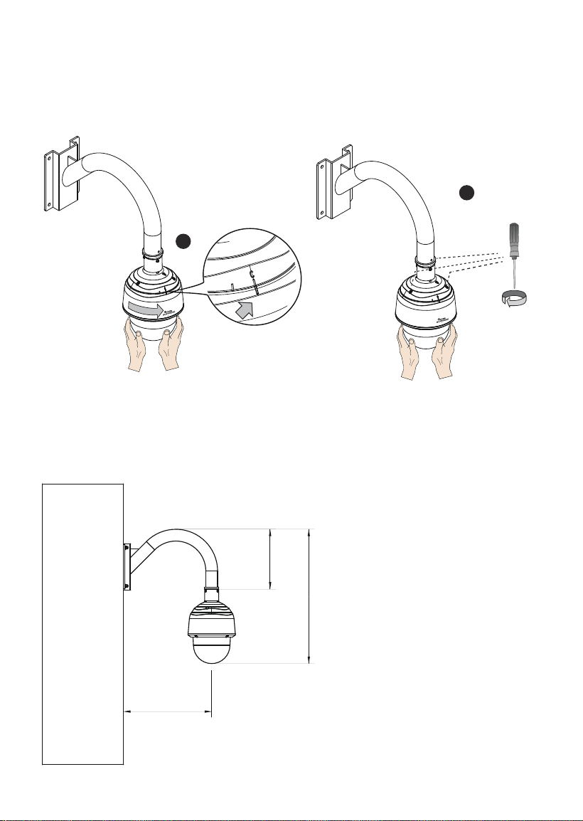
5. Align the camera body with the top section. Align the
alignment mark on the camera with that on the interface
section. Push the camera up to match the top section.
Install AM-519 adaptor
to the gooseneck.
Alignment mark
16
6. Rotate the camera clockwise until its alignment mark is aligned with the "C" mark.
7. Use the included T25 stardriver to tighten the 3 anti-tamper screws from the top. Make
sure all parts have been securely tightened.
6
7
HD WDR Pro
HD WDR Pro
The dimensions of the gooseneck installation are shown below.
380.4
258
579
C mark
17
English
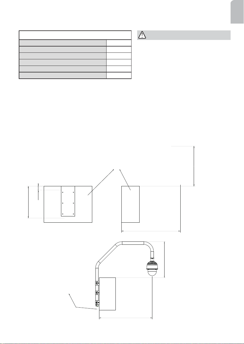
IV-3. Parapet Mounting: AM-231
The screws included in the parapet set are:
Sleeve anchors 5/16" x3" 6
Hex bolts M8x25 6
Hex bolts M8x70 3
Hex lock nuts M8 6
Washers M8 15
Lock washers M8 15
978.4
665
978.4
665
65
528
Parapet
Front view
Side view
Room for routing cables
The parapet bracket is designed for installation on the inside of a parapet. Note the
following before you start to install:
1. There must be a clearance of 65mm between the upper edge of the parapet wall and
the metal bracket xed to the wall. You can ush align the upper edge of the alignment
sticker with the edge of a parapet wall.
2. At least two inches of space should be available below the parapet bracket for routing
cables.
The space requirements for a parapet mount are shown below:
The parapet wall should have a
concrete strength of 4000 PSI or higher.
Each sleeve anchor can withstand an
800kgs pull-out force.
IMPORTANT:
18
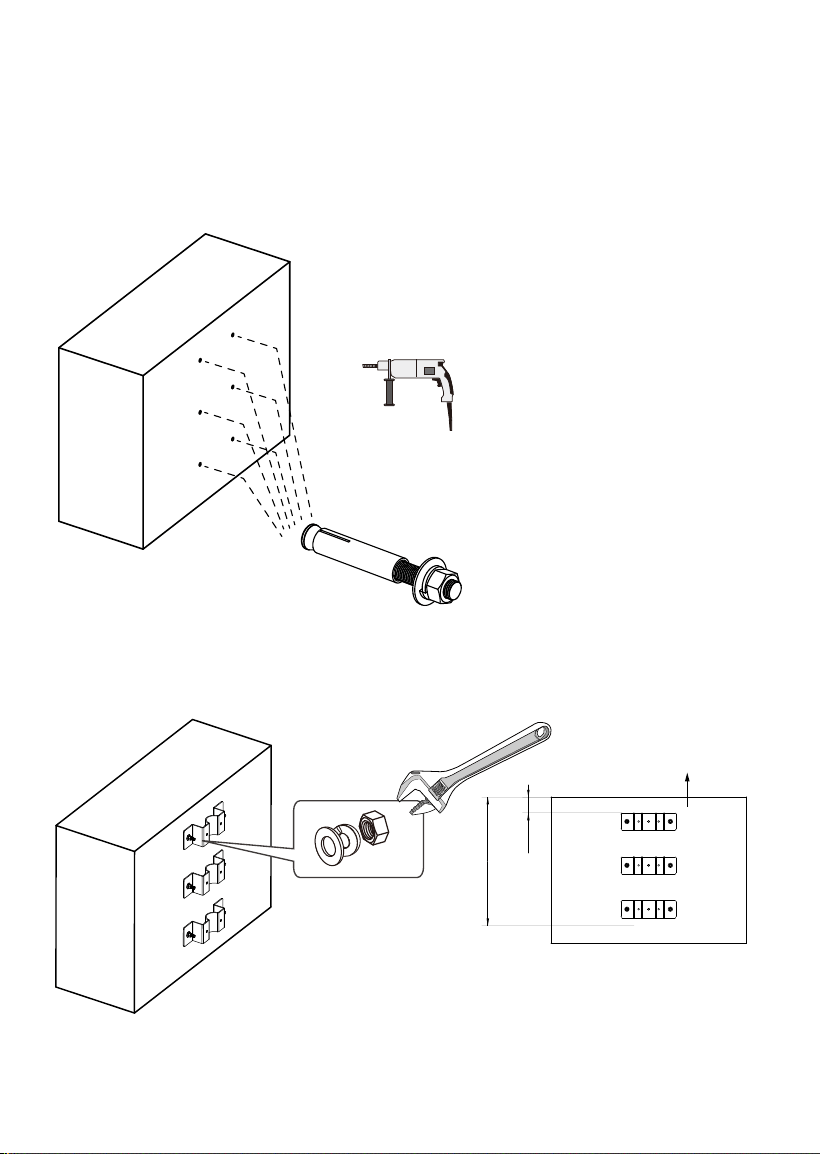
Below is a sample procedure using the parapet mount bracket:
1. Determine a hard surface location. Use the alignment sticker to mark the positions
where holes will be drilled for the bracket.
2. Drill 6 pilot holes (10mm in diameter and 5.5cm deep) into the wall, and then hammer
in the sleeve anchors. Note that you should hammer the anchors with hex nuts and
washers on them so that the threaded poles will not be deformed!
65
528
Parapet wall
3. Install the brackets to wall using the hex nuts and washers from the sleeve anchors.
19
English
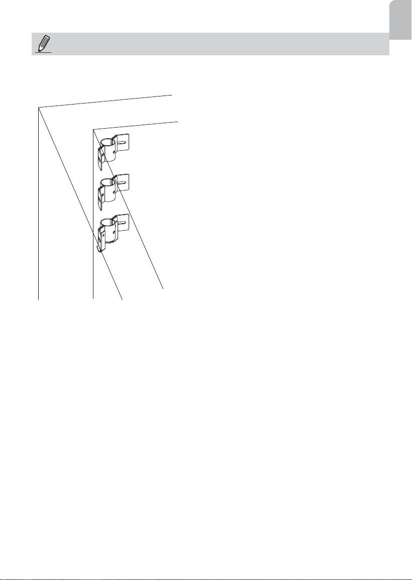
If you install the corner parapet bracket, use the included alignment sticker, and mark the
drill holes through the mounting slots on the brackets.
NOTE:
20
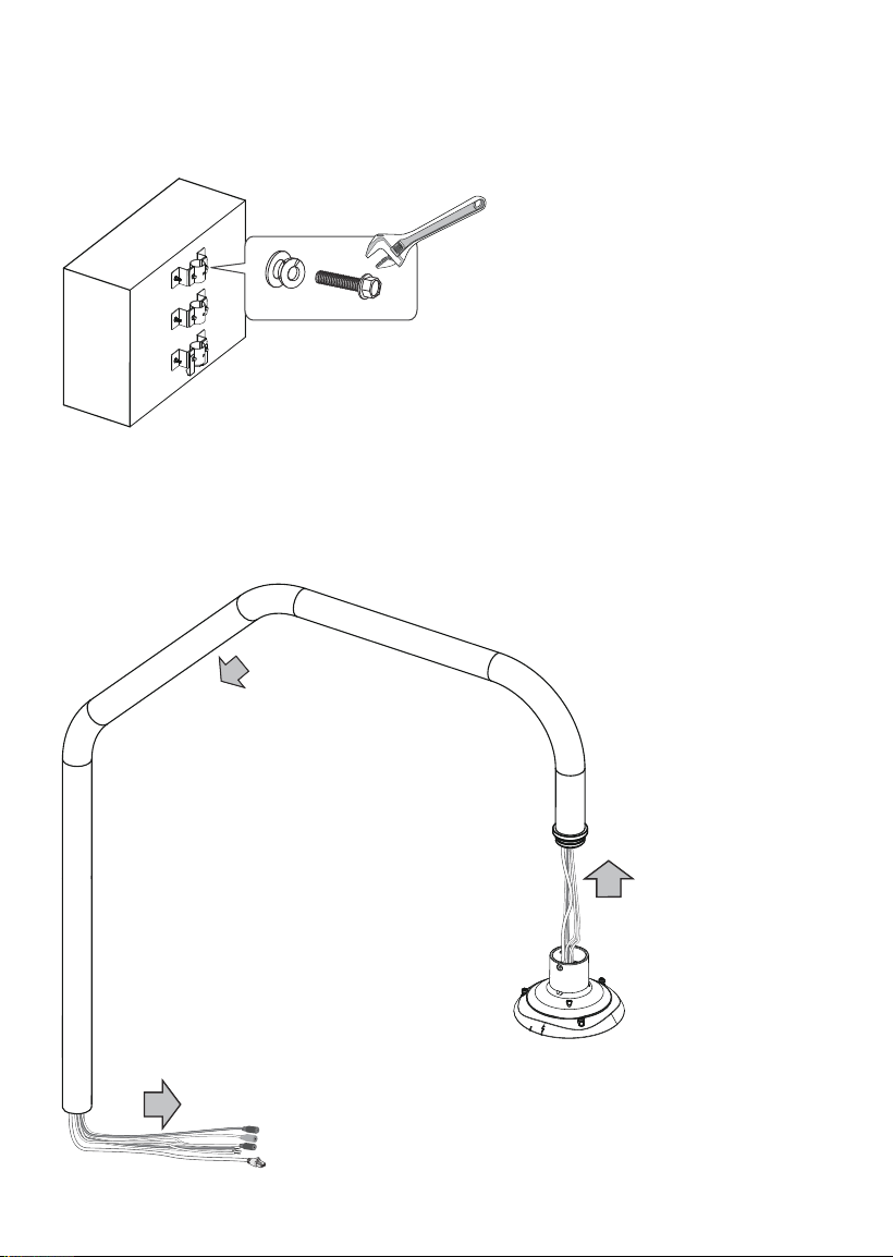
4. Use a crescent wrench to secure the outer brackets to the brackets on the wall using
the M8x25 hex bolts and washers. Do not completely tighten the bolts yet! When the
speed dome is installed to the mount pipe, it needs to be swiveled out to the desired
position.
6. Feed cables through the pipe arm. The cable length for passing through the pipe arm is
250cm at least. You can pass a rigid copper wire through the pipe arm rst, and use it to
pull other wires through the pipe.
5. Install the AM-519 adapter to the parapet pipe.
21
English
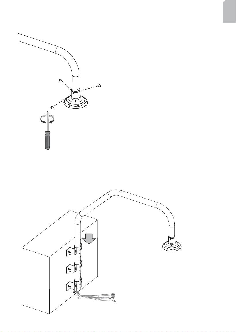
7. Install the top section of the camera to the pipe arm by driving 3 M5 x8 screws.
8. Insert the pipe arm into the round openings on the brackets until it is rested on the
bottom bracket.
22
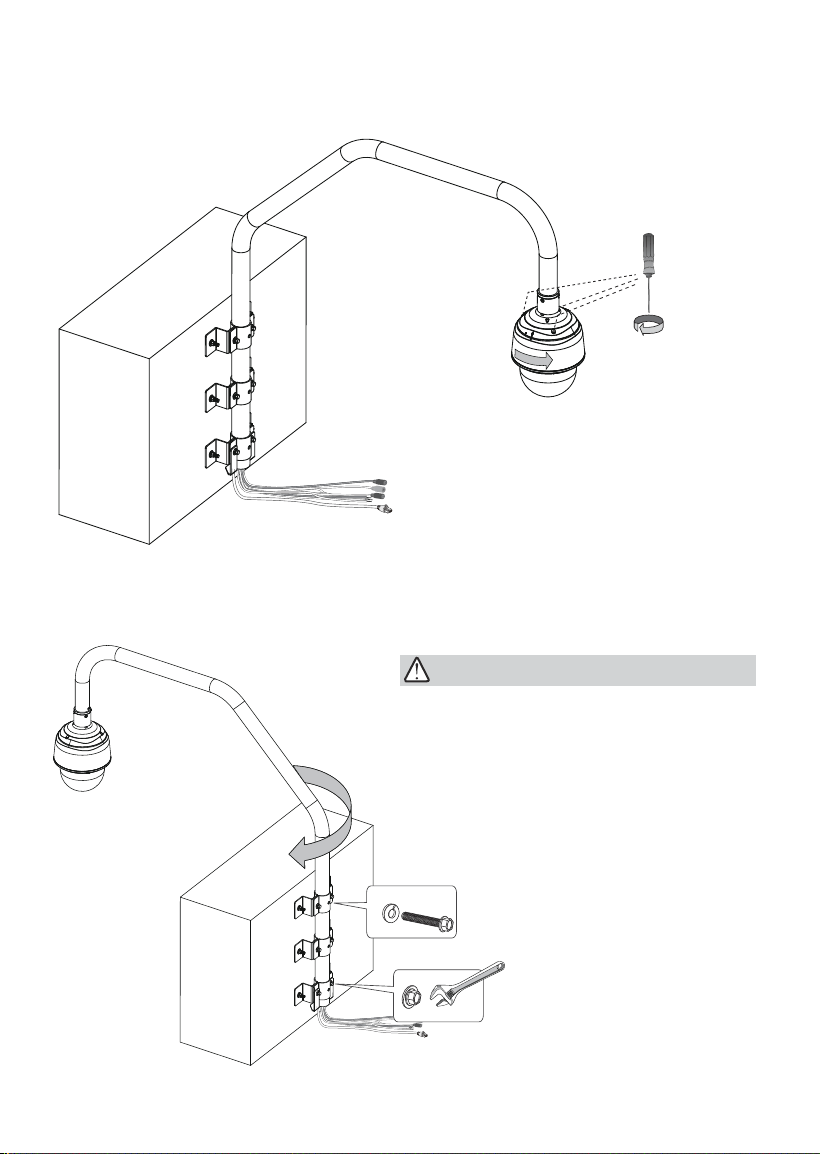
9. Install the camera to the top section. For installation details, refer to the Quick
Installation Guide or page 15 in this document.
10. Swivel the pipe arm outwards to the opposite position. Use the M8 x70 bolts to secure
the pipe arm to the brackets. You also need to tighten the M8 x25 bolts between the
inner and outer brackets.
IMPORTANT:
When inserting the M8 bolts, you may
damage the cables inside. Try twist the
bolts a bit to get around cables if you feel
resistance when inserting through the pipe.
23
English
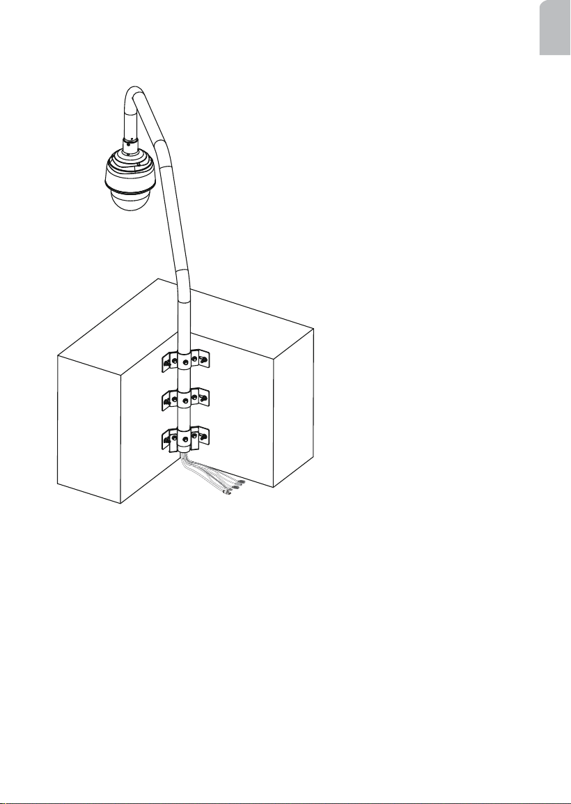
A corner parapet installation should look like this when its installation is completed.

24
This page is intentionally left blank.