PRODUCT DATA
The Honeywell Trademark is used under license from Honeywell International
Inc. by Air-Pure Systems.
Honeywell International Inc. makes no representations or warranties with
respect to this product.
68-0198-2
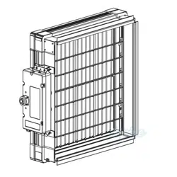
F111 (Series 1,2,3)
In Ceiling Media Air Cleaner
APPLICATION
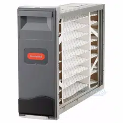
The F111 (Series 1,2,3) Ceiling Media Air Cleaner is a media
air cleaner that uses either a single-speed or three-speed
direct drive forward curve blower motor with particle filter.
When equipped with CPZ™ modules (2), gases and odors are
adsorbed from the air passing through the unit. The air
cleaner removes airborne particles such as dust, soot, mold
spores, pollen and some cooking smoke from the air
circulated through the filter.
FEATURES
• High Efficiency Particulate Air (HEPA) filter models are
99.97% efficient and the hospital grade particle filter
models are 95% efficient at 0.3 micron particles. Both
models are more efficient on particles smaller and
larger. There is also a 95% ASHRAE model.
• Circulates up to 1250 cfm.
• Designed to overcome the increase in air flow
resistance normally caused by filter loading.
• White or black color cover to complement the ceiling.
• CPZ™ module removes up to 95% of the space odors
for up to 24 months.
• 3-Speed remote wall switch ( 3-speed models only)
• READ AND SAVE THESE
INSTRUCTIONS
Contents
Application.........................................................................1
Features ............................................................................1
Specifications ....................................................................2
Ordering Information .........................................................2
Planning the Installation ....................................................3
Installation .........................................................................4
Operation...........................................................................7
Service ..............................................................................8
Parts List ...........................................................................9
Limited Two-Year Warranty ...............................................12
F111 (SERIES 1,2,3) IN CEILING MEDIA AIR CLEANER
68-0198-2 Release 5-09 2
ORDERING INFORMATION
If you have additional questions, need further information, or would like to comment on our products or services, please write or
phone:
1. Your local Honeywell Commercial Air Products Distributor.
2. Air-Pure Systems
16873 Fish Point Rd. SE
Prior Lake, MN 55372
www.cleanairfacility.com
Phone: (800) 998-1919
Fax: (800) 221-3248
SPECIFICATIONS
IMPORTANT
The specifications given in this publication do not
include normal manufacturing tolerances. Therefore,
this unit may not exactly match the listed specifica-
tions. Also, this product is tested and calibrated
under closely controlled conditions, and some minor
differences in performance can be expected if those
conditions are changed.
Models: Refer to Table 1 for model descriptions.
Grill Color: White (standard) or Black (add ‘B’ to end of
model number).
Blower/Motor: Single speed (standard) or three speed ( add
‘-3S’ to the end of the model number) direct drive forward
curve.
Dimensions: See Fig. 1 for dimensions.
Table 1. F111 (Series 3) Description.
a
For single-speed and three-speed systems (set to High)
b
F111C1061 has a new model number : F111C1012B
To Order F111 with a Black Grill
Replace the ‘W’ with a ‘B’ to any model number in Table 1.
Model Voltage
Efficiency
Gas, V.O.C. and
Odor Control
Modules (2)
Air Volume
a
in cfm
(m
3
/hr)
Particulates at
0.3 Micron
(DOP Test)
V.O.C./Odor
(Most Gases/
Odors First Pass
Average)
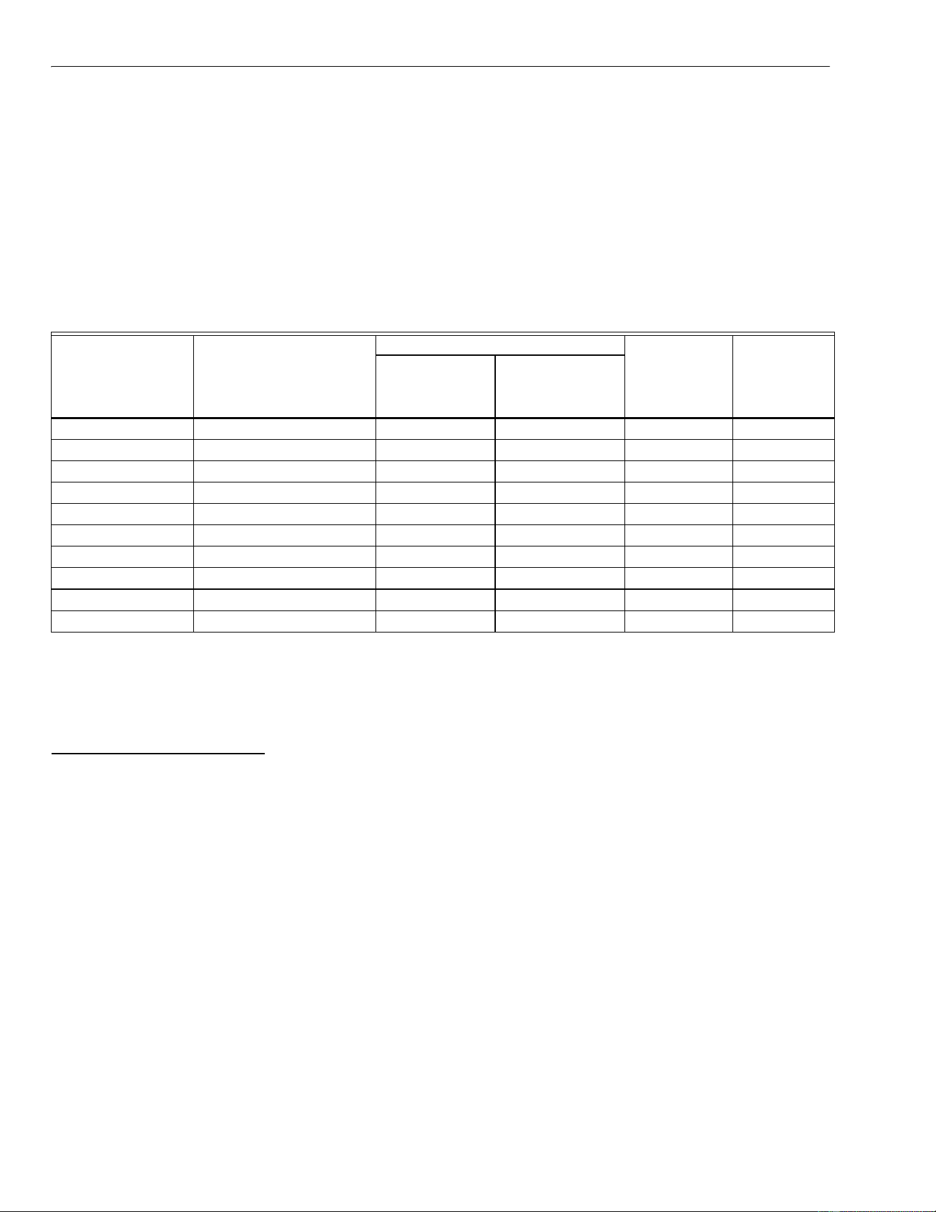
F111A1253W-3S 120 Vac, 60 Hz, 8.5A 95% ASHRAE N/A N/A 1250 (2120)
F111A1063W-3S 120 Vac, 60 Hz, 7.2A 99.97% HEPA N/A N/A 950 (1610)
F111C1073W-3S 120 Vac, 60 Hz, 7.5A 95% ASHRAE 85% CPZ™ modules 1150 (1950)
F111C1003W-3S 120 Vac, 60 Hz, 7.0A 99.97% HEPA 85% CPZ™ modules 825 (1400)
F111C1012W-3S 120 Vac, 60 Hz, 8.0A 95% at 0.3 micron 85% CPZ™ modules 1125 (1910)
F111A2253W-3S 230 Vac, 50 Hz, 4.2A 95% ASHRAE N/A N/A 1125 (1910)
F111A2007W-3S 230 Vac, 50 Hz, 3.5A 99.97% HEPA N/A N/A 900 (1530)
F111C2073W-3S 230 Vac, 50 Hz, 4.0A 95% ASHRAE 85% CPZ™ modules 1025 (1740)
F111C2003W-3S 230 Vac, 50 Hz, 3.2A 99.97% HEPA 85% CPZ™ modules 825 (1400)
F111C1053W-3S 230 Vac, 50 Hz, 3.5A 95% at 0.3 micron 85% CPZ™ modules 950 (1610)
F111C1061
b
N/A = not applicable.
same as F111C1012B-3S
F111 (SERIES 1,2,3) IN CEILING MEDIA AIR CLEANER
3 68-0198-2
Table 2. F111 Air Volume Specifications for 3 Speed Models (Series 3).
a
Same for Single Speed Models (Series 1 & 2).
.
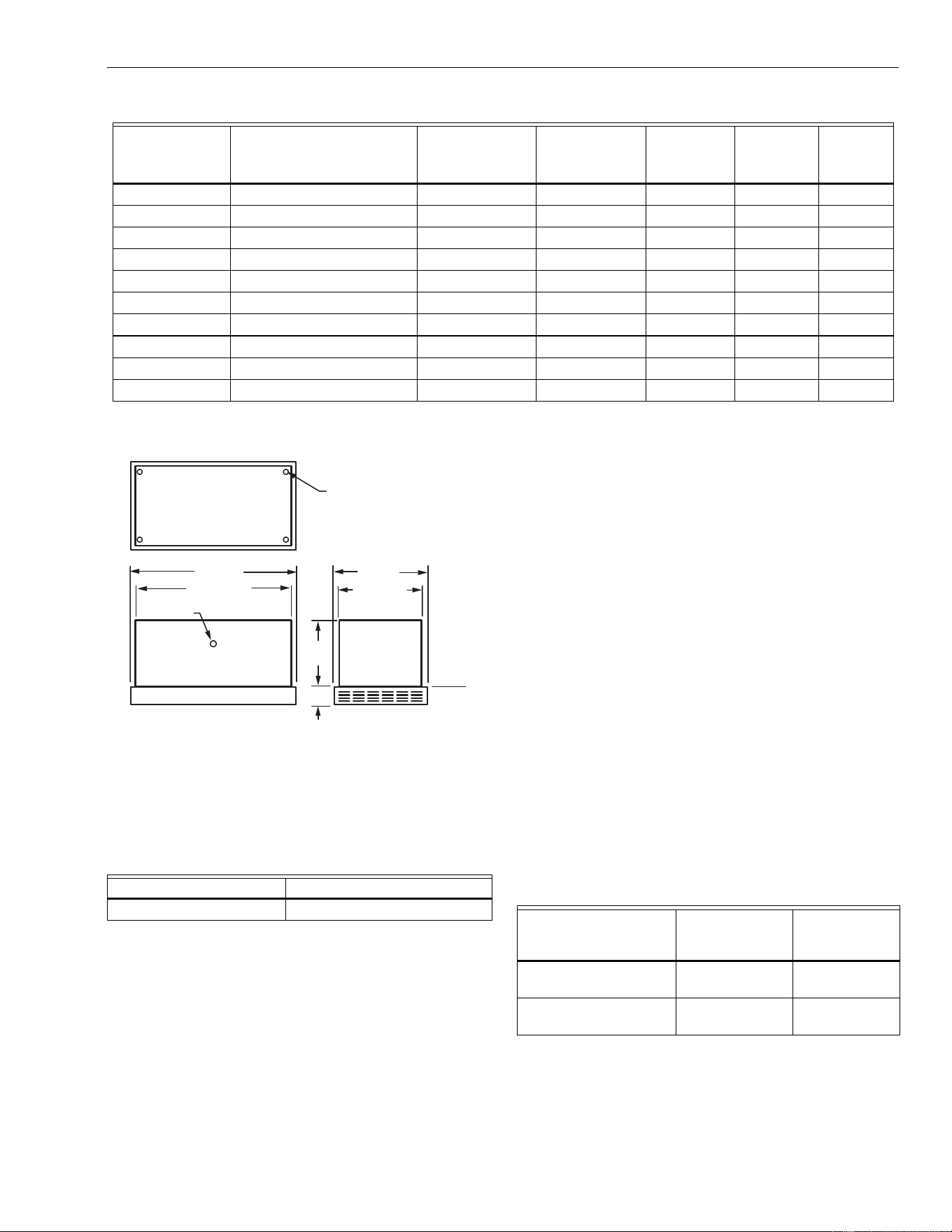
Fig. 1. Approximate dimensions of F111
(Series 1,2,3) in in. (mm).
Installation Weight:
Approximately 115 lb to 155 lb (kg) depending on the filter
configuration. Refer to Table 3.
Table 3. Sorbent Module Weight.
Sound Level at 3.3 ft (1m):
Low speed: 53 dBA (3 speed models only).
Medium speed: 57 dBA (3 speed models only)
High speed: 61 dBA.
Grille Type: Perforated metal.
Mounting: Recesses into opening on the ceiling.
Approvals:
Underwriters Laboratories Inc.: Listed.
Canadian Standards Association: Listed.
Accessories:
Black Color Grill
Remote 3-Speed Wall Switch
Replacement Parts See Parts List, Table 5.
PLANNING THE INSTALLATION
The number of F111 (series 1,2,3) air cleaners that are needed
is determined by taking into account the number of occupants
and the volume of the space. Type of contamination, outdoor
air quality and use of the area are also factors. Refer to Table
3 for general guidelines when determining how many air
cleaners are needed.
EXAMPLE: One air cleaner can provide 2.5 air changes per
hour in a 24,000 cubic feet (720 cubic meters) no
smoking area. Table 3 suggests two air cleaners
for a 24,000 cubic feet area because most areas
have contaminants that require more units to
provide quality air.
If any questions should arise concerning determining the
number of air cleaners needed for an area, consult your
distributor or local Honeywell Commercial Air Cleaner
Distributor.
Table 4. Determining the Minimum Number of
Air Cleaners Needed for a Space.
Model Voltage
Particulates at
0.3 Micron
(DOP Test)
Gas, V.O.C. and
Odor Control
Modules (2)
High
a
in cfm
(m
3
/hr)
Medium
in cfm
(m
3
/hr)
Low
in cfm
(m
3
/hr)
F111A1253W-3S 120 Vac, 60 Hz, 8.5A 95% ASHRAE N/A 1250 (2120) 800 (1360) 450 (760)
F111A1063W-3S 120 Vac, 60 Hz, 7.2A 99.97% HEPA N/A 950 (1610) 775 (1310) 450 (760)
F111C1073W-3S 120 Vac, 60 Hz, 7.5A 95% ASHRAE CPZ™ modules 1150 (1950) 825 (1400) 450 (760)
F111C1003W-3S 120 Vac, 60 Hz, 7.0A 99.97% HEPA CPZ™ modules 825 (1400) 700 (1190) 450 (760)
F111C1012W-3S 120 Vac, 60 Hz, 8.0A 95% at 0.3 micron CPZ™ modules 1125 (1910) 825 (1400) 450 (760)
F111A2253W-3S 230 Vac, 50 Hz, 4.2A 95% ASHRAE N/A 1125 (1910) 700 (1190) 475 (810)
F111A2007W-3S 230 Vac, 50 Hz, 3.5A 99.97% HEPA N/A 900 (1530) 600 (1020) 400 (680)
F111C2073W-3S 230 Vac, 50 Hz, 4.0A 95% ASHRAE CPZ™ modules 1025 (1740) 675 (1150) 450 (760)
F111C2003W-3S 230 Vac, 50 Hz, 3.2A 99.97% HEPA CPZ™ modules 825 (1400) 550 (930) 375 (640)
F111C1053W-3S 230 Vac, 50 Hz, 3.5A 95% at 0.3 micron CPZ™ modules 950 (1610) 625 (1060) 425 (720)
Media Weight in lb (kg)
CPZ™ modules (2) 43 (20)
22-1/2 (572)
24 (610)
3/8 X 16
INTERNAL
THREAD (4)
46-3/4 (1187)
48 (1219)
17-1/4
(438)
4-1/2
(114)
TOP VIEW
POWER CONNECTION
POINT
CEILING
LINE
M11996A
Space Volume
(L x W x H) in Cubic
Feet (Cubic Meter)
Number of
Persons Present
Minimum
Number of Air
Cleaners
12000 to 18000
(360 to 540)
30 to 60 1
18001 to 35000
(540 to 1050)
61 to 90 2
F111 (SERIES 1,2,3) IN CEILING MEDIA AIR CLEANER
68-0198-2 Revised 5-09 4
WARNING
TO REDUCE THE RISK OF FIRE,ELECTRICAL
SHOCK, OR INJURY TO PERSONS,OBSERVE THE
FOLLOWING:
1. Installation Work And Electrical Wiring Must Be Done
By Qualified Person(s) In Accordance With All Applica-
ble Codes And Standard, Including Fire Rated Con-
structions.
2. When Cutting Or Drilling Into The Wall Or Ceiling, Do
Not Damage Electrical Wiring And Other Hidden Utili-
ties.
3. Never Place A Switch Where It Can Be Reached From
A Tub Or Shower.
4. Use This Unit Only In The Manner Intended By The
Manufacturer. If You have Questions, Contact The Man-
ufacturer.
5. Before Servicing Or Cleaning Unit, Switch Power Off At
Service Panel And Lock Service Panel To Prevent
Power From Being Switched on Accidentally.
6. If This Unit Is To Be Installed Over A Tub Or Shower, It
Must Be Marked As appropriate For The Application
and be connected to a GFCI (Ground Fault Circuit Inter-
rupter) - protected branch circuit.
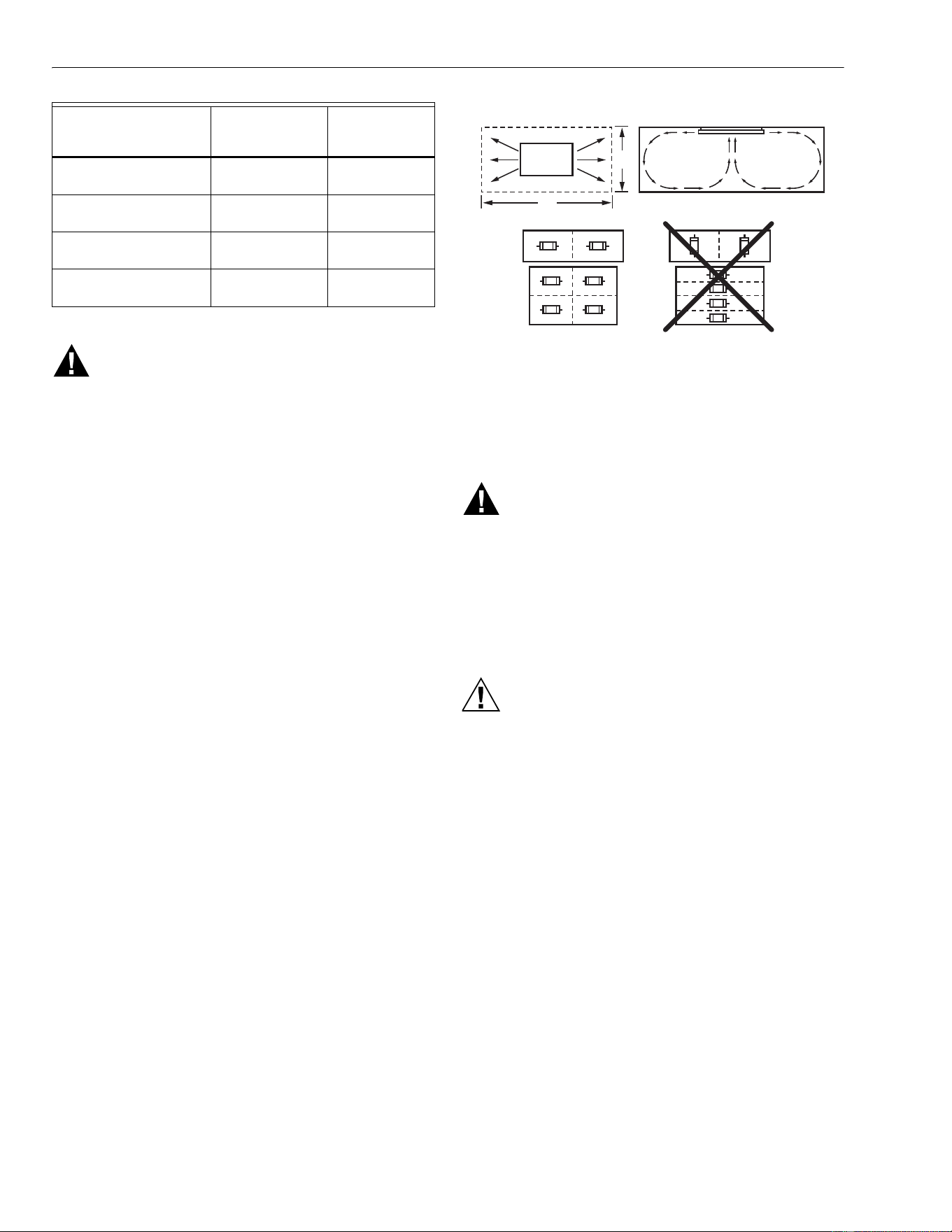
Choose Location
Choosing the correct location for the air cleaner affects the
overall performance of the unit. The bidirectional airflow
pattern must flow into the longest reaches of the zone being
cleaned. See Fig. 2
NOTE: The F111 Has Not Been Investigated
For Use In Fire Resistance Rated
Construction.
Fig. 2. Correct positioning of the air cleaner
for optimum cleaning.
The air cleaner is designed to be suspended centrally in a
space and mounted into or on a ceiling. The cleaning footprint
of the air cleaner is rectangular with air patterns that move
clean air to the corners of the area while drawing contaminated
air up from the center of the area. See Fig. 2.
When multiple air cleaners are installed, the allotted areas to
be cleaned should be equal. The air throw in one direction is
approximately 55 ft (17m). Air velocity at 90 ft per minute
(27m per minute) is considered end of throw.
IMPORTANT
Never hang the air cleaner higher than 16 ft (5m)
above the floor.
INSTALLATION
WARNING
Explosion Hazard Possible.
Can cause personal injury or equipment damage.
Do not install or use the F111 (series 11000) air
cleaner where there is any danger of gas, vapor or
dust explosion.
IMPORTANT
This air cleaner has not been investigated for use in
the ceilings of fire-resistant assemblies.
CAUTION
Electrical Hazard.
Can cause personal injury or equipment damage.
Turn off power before installing or servicing the air
cleaner.
IMPORTANT
Stand on a stable platform when working with the air
cleaner.
When Installing this Product…
1. Read these instructions carefully. Failure to follow them
could damage the product or cause a hazardous condi-
tion.
2. Check the ratings given in the instructions and on the
product to make sure the product is suitable for your
application.
3. Installer must be a trained, experienced service techni-
cian.
4. After installation is complete, check out product opera-
tion as provided in these instructions.
Unpack the Air Cleaner
Check that all components are included. The unit consists of:
• cabinet and grille/door assembly,
• media modules,
• literature.
35001 to 51000
(1050 to 1530)
91 to 120 3
51001 to 65000
(1530 to 1950)
121 to 180 4
65001 to 80000
(1950 to 2400)
181 to 240 5
80001 to 95000
(2400 to 2850)
241 to 300 6
Space Volume
(L x W x H) in Cubic
Feet (Cubic Meter)
Number of
Persons Present
Minimum
Number of Air
Cleaners
F111
(SERIES
11000)
CLEANING FOOTPRINT
CEILING
FLOOR
CORRECT
2
1
INCORRECT
M12652A
F111 (SERIES 1,2,3) IN CEILING MEDIA AIR CLEANER
5 68-0198-2
• latches (2)
• 3-speed switch module ( 3 Series only)
Make Opening (if Mounting in a Drop Ceiling)
1. Size the opening to fit the air cleaner cabinet as closely
as possible.
2. Frame the opening to provide adequate support for the
cabinet. The cabinet must fit snugly in the opening;
allow no more than 1/4 in. (6 mm) from the opening to
each side of the cabinet.
3. Cover the framing and any unused portion of the open-
ing with wallboard, plywood, or other material and finish
to match the ceiling.
Electrical Hookup
All wiring must comply with applicable codes and ordinances.
The power source must agree with the model type: 120V,
60 Hz or 230V, 50 Hz.
1. Locate the prepunched hole in the side of the cabinet.
2. Remove the air cleaner lid.
3. For Series 1 and 2 only.
Remove the connection box
cover plate in the center cavity of the air cleaner.
4. For Series 3 only. Remove the connection box cover
plate on the bottom, underneath the tray.
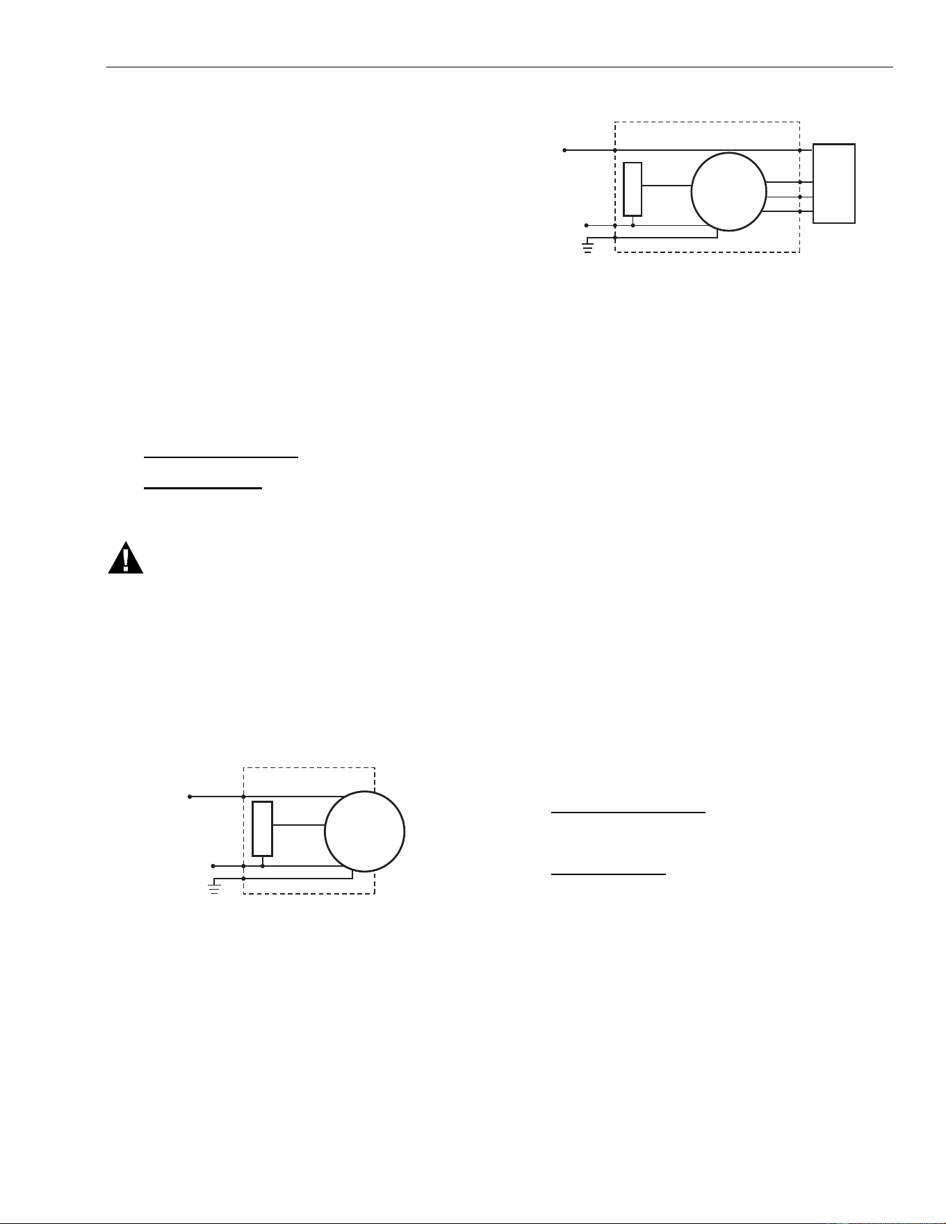
5. Refer to Fig. 3 and 4 for typical electrical diagrams.
WARNING
Risk of Fire or Electric Shock.
Can cause personal injury or equipment damage.
Use only Honeywell 190097C Remote Speed Switch
(3-speed models only) to regulate air cleaner speed.
Using a different speed switch may void the warranty.
IMPORTANT
• Be sure the air cleaner is grounded for correct
operation and safety.
• Canadian installation: NEVER install in ceilings with
thermal insulation value greater than R-40.
Fig. 3. Typical F111 (series 1 & 2) 120V, 60 Hz or
208/230V, 50/60 Hz wiring diagram.
Fig. 4. Typical F111 Series 3 only 120V, 60 Hz or
230V, 50 Hz wiring diagram.
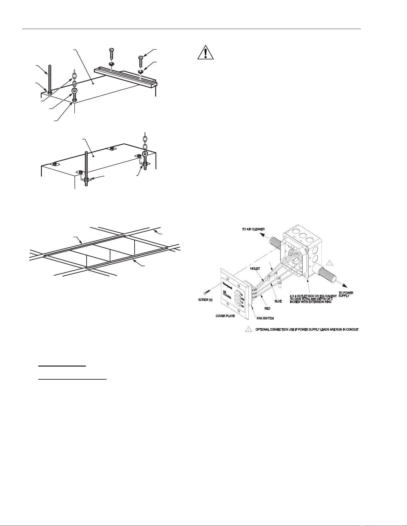
Mount Air Cleaner Cabinet
The air cleaner can be mounted in a drop ceiling system or
hung in an open area. Both mounting methods require the air
cleaner to be level and positioned facing downward for correct
operation.
1. Remove the door/grille from the carton and set it aside.
2. Remove all filters.
3. Fit the cabinet into the prepared ceiling opening or
position on the ceiling.
4. Use the four 3/8 x 16T internal nuts (one at each corner)
to fasten the cabinet to a structural support (bar joist,
concrete slab or timber framing). See Fig. 5.
NOTES:
• All external hardware is furnished by the installer.
• When using the suspension system of mounting,
be sure to include a means for leveling adjust-
ment after installation.
• Never rest the air cleaner on the T-bar.
5. Level the air cleaner.
6. Turn the air cleaner power on and check for proper
operation for 2 to 3 minutes. There should be a smooth,
powerful blower sound and air discharging from both
ends of the air cleaner.
7. Turn off the power.
8. Install the particle filter. Note airflow direction arrows if
present. Install the filter with the direction arrow pointing
towards the motor.
9. For Series 1 and 2 only.
Fasten the filter tabs. Be sure
there is a snapping sound when fastened. The tabs are
commercial Velcro and require more force than lightly
pushing them together.
10. For Series 3 only.
Lock and secure the particle filter
into place by closing both latches.
M12657
CAPACITOR
WHITE
GREEN
BLACK
FACTORY WIRING
BROWN
EXTERNAL
WIRING BY
INSTALLER
MOTOR
A100002
CAPACITOR
WHITE
GREEN
BLACK
FACTORY WIRING
BROWN
EXTERNAL
WIRING BY
INSTALLER
MOTOR
BLUE
VIOLET
RED
BLACK
REMOTE 3-SPEED
SWITCH
F111 (SERIES 1,2,3) IN CEILING MEDIA AIR CLEANER
68-0198-2 Revised 5-09 6
Fig. 5. Fasten cabinet to a structural support.
IMPORTANT
Do not touch the pleated filter media. Handle only the
filter frame to prevent damage to the filter media.
11. Remove CPZ™ sorbent modules (select models) from
their packaging and install one module into each cavity.
12. For Series 1 only
. Be sure the fastener tabs are facing
downward and fasten them.
13. For Series 2 and 3 only.
Be sure both catches are
turned down and filter rests firmly on catches.
14. Install the prefilter in the air cleaner lid. Position the
metal screen mesh so it is facing upward when the lid is
closed.
Remote 3 Speed Wall Switch (3 Speed Models only)
The 190097C Remote Wall Switch Assembly allows control of
the F111 model air cleaners from a a location separate from
the air cleaner. The assembly includes a remote switch with
an outlet box cover, outlet box, extension ring, and a wire
harness. Wiring to connect the remote switch and air cleaner
must be furnished separately.
CAUTION
• This installation to be performed only by a qualified
installer.
• All wiring to comply with local electrical codes.
• Disconnect power to air cleaner at fuse or breaker
before beginning work. Failure to do so can result in
shock hazard endangering equipment and personal
safety of installer.
• Only one air cleaner can be connected to a remote
switch
1. Disconnect power to air cleaner.
2. Mount 4” x 4” outlet box at desired remote location.
3. Attach 3/4” extension ring to outlet box.
4. Run five conductor, color-coded, 18-gauge wires from
the remote switch location to the air cleaner.
5. Use three wire nuts to connect three color-coded, lead
wires on the remote switch to three color-coded wires
from the air cleaner. (Red, Blue, Violet)
6. Use one wire nut to connect white color-coded, lead
wire from the air cleaner to single color-coded wire from
the power supply. (White)
Fig. 6. Wiring 3-Speed Remote Switch
7. Connect the ground wire from the power supply to a
ground stud of the outlet box.(Green)
8. Connect the ground wire from the air cleaner to the
ground stud of the outlet box.(Green)
9. Use one wire nut to connect the black color-coded, lead
wire on the remote switch to the black color-coded wire
from the power supply.
10. Fold wires into box and mount remote switch on outlet
box. Leave switch in OFF position.
11. On the air cleaner remove two screws on wiring com-
partment cover and open
12. Run five conductor, color coded, 18 gauge wires from
the remote switch through the air cleaner access open-
ing into the wiring compartment. Strip ends of remote
switch lead wires
13. Connect three wires on air cleaner to remote switch
lead wires with wire nuts following color code used at
remote switch. (Red, Blue, Violet)
CHAIN
NOTE:
FASTEN SECURELY TO STRUCTURAL
SUPPORT SYSTEM, I.E. BAR JOIST,
CONCRETE SLAB OR TIMBER FRAMING.
HEX BOLT
LOCK
WASHER
M10892
TOP OF METAL CABINET
EYEBOLT
BOTTOM FLANGE AGAINST
UNDERSIDE OF TEES
JAM NUT
3/8 IN. X 16T
"Z" BRACKET (4)
JAM
NUT
THREADED
ROD
BOTTOM VIEW OF
UNIT WITHOUT
LID ASSEMBLY
CEILING
TEE
O
R
U
SI
N
G OPTIO
NA
L
"
Z
"
BRACK
ETS
TOP OF METAL CABINET
A100001
BLACK
F111 (SERIES 1,2,3) IN CEILING MEDIA AIR CLEANER
7 68-0198-2
14. Connect one wire on air cleaner to power supply wire
with a wire nut following color code used at remote
switch. (White)
15. Connect the ground wire from the remote switch to a
ground stud of the wiring compartment cover.(Green)
16. Fold wires into wiring compartment. Replace wiring
compartment cover.
17. Turn on power to air cleaner at fuse or breaker.
18. Check operation by turning air cleaner at HIGH,
MEDIUM, and LOW. Note
that only the remote switch
will operate the air cleaner.
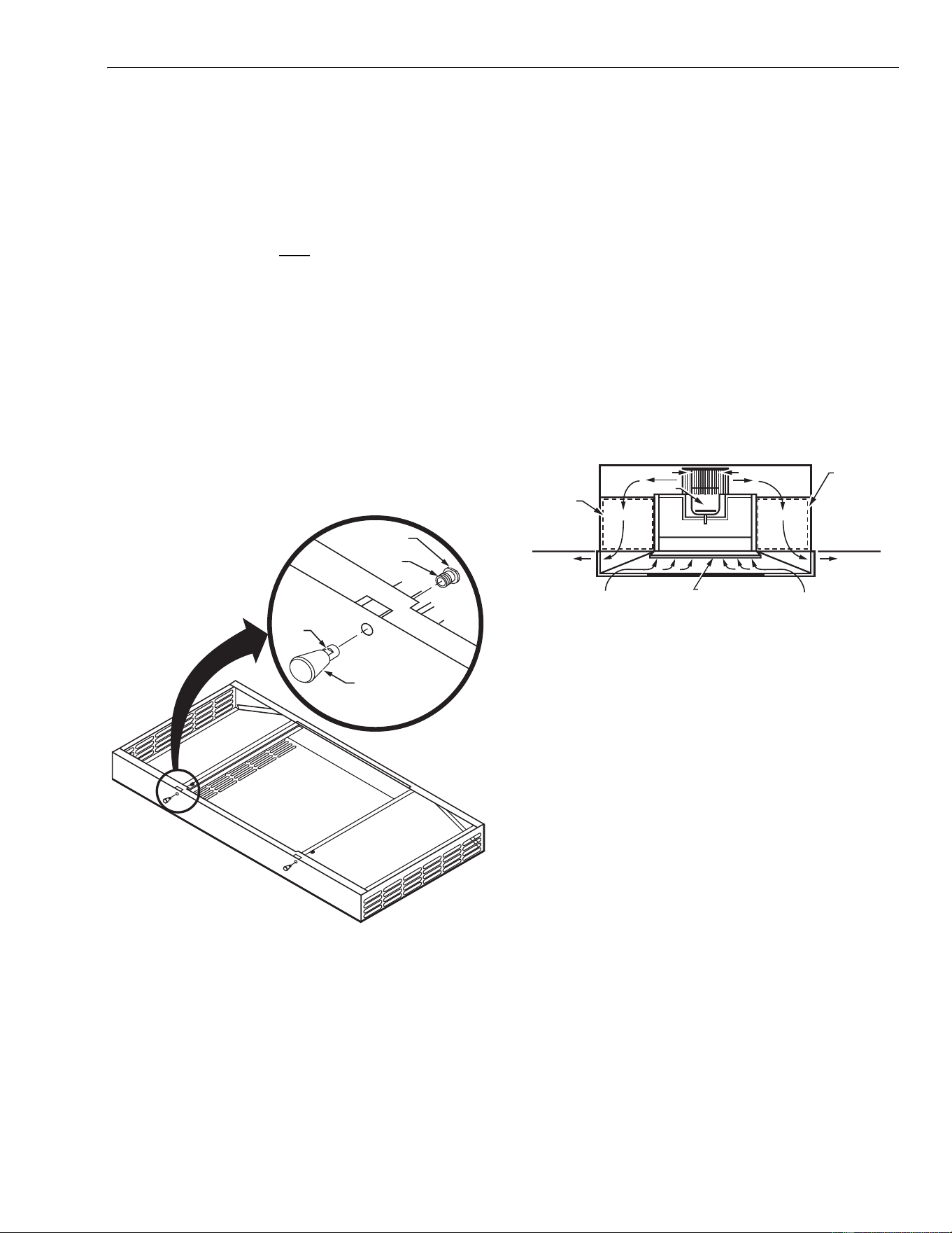
Lid Assembly
The F111 lid is held in place by two separable hinges and two
spring loaded plungers. To install the spring loaded plungers
on the lid follow these steps:
1. Pull the plunger back and twist a quarter turn to reveal
the wrench flat on the body of the spring loaded plunger
(see Fig 7.)
2. Turn the threaded barrel out of the spring plunger.
3. Insert the threaded barrel through the hole in the lid and
turn the spring loaded plunger onto it.
4. Tighten the assembly with wrenches.
5. Repeat steps 1 through 4 for the second plunger.
Fig. 7. Lid assembly.
Opening/Closing the Lid
To open the lid, pull the spring loaded plungers back to
disengage the plunger. Carefully swing the lid open on the
hinges while supporting the filter and/or adsorbent modules as
required. To close, swing the lid into the closed position and
engage the plungers.
Removing /Replacing the Lid
IMPORTANT
The lid is heavy. Make sure that it is supported
before removing.
To remove the lid, swing it into the open position. Slide safety
catch to off position. Move the lid to the side to disengage the
hinge pins. Reverse the procedure to replace the lid. Make
sure safety catch is in safe position.
OPERATION
The F111 (series 1,2,3) in Ceiling Media Air Cleaner has been
engineered to improve indoor air quality for commercial and
industrial applications. The filters are the most practical and
effective filtering system for removing atmospheric dust,
pollens, bacteria, viruses, mold spores, smoke, fumes, mists
and aerosols. Refer to Fig. 8.
Fig. 8. F111 (series 1,2,3) air cleaner operation.
The air cleaner is either operating (power on) or off (power
off). There are no other operational options available. Even
when the area is unoccupied, the air cleaner can be operated
continuously to prevent buildup of airborne contaminants.
Operate the air cleaner only when the area is occupied when
specific activities produce contaminants.
The CPZ™ sorbent module has the ability to collect and hold
gas-phase compounds and vapors typically found in
commercial and light industrial facilities. These gases and
vapors frequently appear as odors that, at times, can be
annoying and irritating. The modules become saturated after
collecting 25% to 50% of their weight in gaseous odors. The
quantity of CPZ™ material provides adequate dwell time to
ensure up to 95% collection efficiency in the first pass. This
also provides a long maintenance-free service life.
The minimum recommended air exchange rate is 2.5 times
per hour. In a heavily contaminated area, up to 15 air
exchanges per hour can be necessary. The factors that
determine what the rate of air exchange should be are:
• generation rates of the various pollutants;
• concentration level of the pollutants;
• desired contamination reduction level.
Airborne contaminants will always be present in the air where
contaminant generations take place. Air cleaning systems and
ventilators do not eliminate airborne contaminants, they
reduce the excessive accumulation of the contaminants. To
eliminate the contamination, the source of contamination must
be removed.
THREADED
BARREL
SPRING
LOADED
PLUNGER
WRENCH FLAT
WRENCH
FLAT
M11994
M12651A
CEILING LINE
CLEAN AIR
DISCHARGE
CEILING LINE
CLEAN AIR
DISCHARGE
PARTICLE FILTER
PREFILTER
AIR IN
AIR IN
INTAKE
BLOWER
MOTOR
AIR VENTS
CPZ™
SORBENT
FILTER
MODULE
CPZ™
SORBENT
FILTER
MODULE

F111 (SERIES 1,2,3) IN CEILING MEDIA AIR CLEANER
68-0198-2 Revised 5-09 8
Local, Federal and professional ventilation engineering
standards and codes prescribe minimum ventilation rates to
dilute air contamination in specific applications. The
ventilation rates usually assume the injection of outdoor air
measured as air exchange rate. The use of the F111 (series
1,2,3) air cleaner to comply with ventilation requirements is an
acceptable alternative to ventilation with outdoor air. However,
at least 20% of a specified ventilation rate or code must be
derived from outdoor air. The F111 (series 1,2,3) air cleaner
filtered and recirculated air can be the remaining 80%.
SERVICE
CAUTION
Electrical Hazard.
Can cause personal injury or equipment damage.
Turn off power before installing or servicing the air
cleaner.
IMPORTANT
Be sure to change filters as recommended to prevent
reduced airflow in the air cleaner.Stand on a stable
platform when working with the air cleaner.
The useful life of the CPZ™ sorbent modules may vary from 4
to 24 months, depending on the application. In most
applications, the sorbent media life ranges from 12 to 18
months. The particle filter life ranges from 6 to 24 months with
12 to 24 months as an average. The modules and filters need
to be changed more frequently in facilities that operate 24
hours a day.
Prefilter
The disposable prefilter collects large dust particulates and
lint- type airborne fibers. Check the filter every two weeks to
determine the replacement frequency:
1. Slowly open the lid, supporting the lid so the filters do
not fall out.
2. Remove the dirty prefilter.
3. Install the new prefilter in the air cleaner lid. Position the
metal screen mesh so it is facing upward when the lid is
closed.
4. Close and latch the lid.
Particle Filter
The particle filter collects particulates that pass through the
prefilter. The filter life is typically from 1 to 2 years. There is
decreased air quality and a pulsing sound when the filter is
filled with contaminants. The filter must be replaced when the
pulsing sound is noticed.
NOTE: The filter must be replaced. Washing, vacuuming or
reverse air blasting does not clean it.
1. Slowly open lid, supporting it so the filters do not fall out.
2. Open the securing strips and with both hands. Slide the
filter toward you.
3. Place spent filter in a plastic trash bag and dispose of
properly.
4. Inspect the motor brackets for loose fasteners and
tighten as necessary.
5. Install the new filter noting the direction of airflow arrow.
6. For Series 1 and 2 only
. Fasten the filter tabs. Be sure
there is a snapping sound when they are fastened. The
tabs are commercial Velcro and require more force to
fasten.
7. For Series 3 only.
Lock and secure the particle filter
into place by closing both latches
IMPORTANT
Do not touch the pleated filter media. Handle only the
filter frame to prevent damage to the filter media.
8. Close and latch the lid.
CPZ™ Adsorbent Module
The CPZ™ adsorbent module is used to collect gases,
vapors, odors and volatile organic compounds (V.O.C.) from
the air that passes through the air cleaner. Adsorbents collect
and hold 25% to 50% of their weight in odorous gases and
vapors. The impurities are collected until the adsorbents reach
saturation. At saturation, the adsorbents emit a continuous
strong pungent odor. If the air cleaner is turned off for 8 to 10
hours, there will a temporary odor when it is turned back on. If
the odor persists for 30 minutes, it is time to replace the filters.
NOTE: When tobacco smoke is a contaminant, both the
particle filter and the adsorbent filter will need to be
serviced at the same time.
1. Slowly open the lid, supporting the lid so the filters do
not fall out.
2. For Series 1 only.
Support the adsorbent module with
one hand and release the fastener.
3. For Series 2 and 3. Support the adsorbent module with
one hand and turn open the catches.
4. Use two hands and slide the filter from the housing.
IMPORTANT
The module weighs about 26 lb (12 kg) and can be
hard to handle.
5. Place the spent module in a plastic trash bag and
dispose of properly.
6. Remove CPZ™ sorbent modules from their packaging
and install.
7. For Series 1 only
. Be sure the fastener tabs are facing
downward and fasten them.
8. For Series 2 and 3 only.
Be sure both catches are
turned down and filter rests firmly on catches.
9. Install 1 startup-filter in each end of grill.
10. Close and latch the lid.
On initial startup, a small amount of dust can blow from the air
cleaner. This is normal and stops a few minutes after startup.
The startup-filters will catch all the dust. The startup-filters are
placed in the two exit outlets on the grill. After running the unit
for 5 minutes, turn off the unit. Remove and discard the two
start-up filters.
F111 (SERIES 1,2,3) IN CEILING MEDIA AIR CLEANER
9 68-0198-2
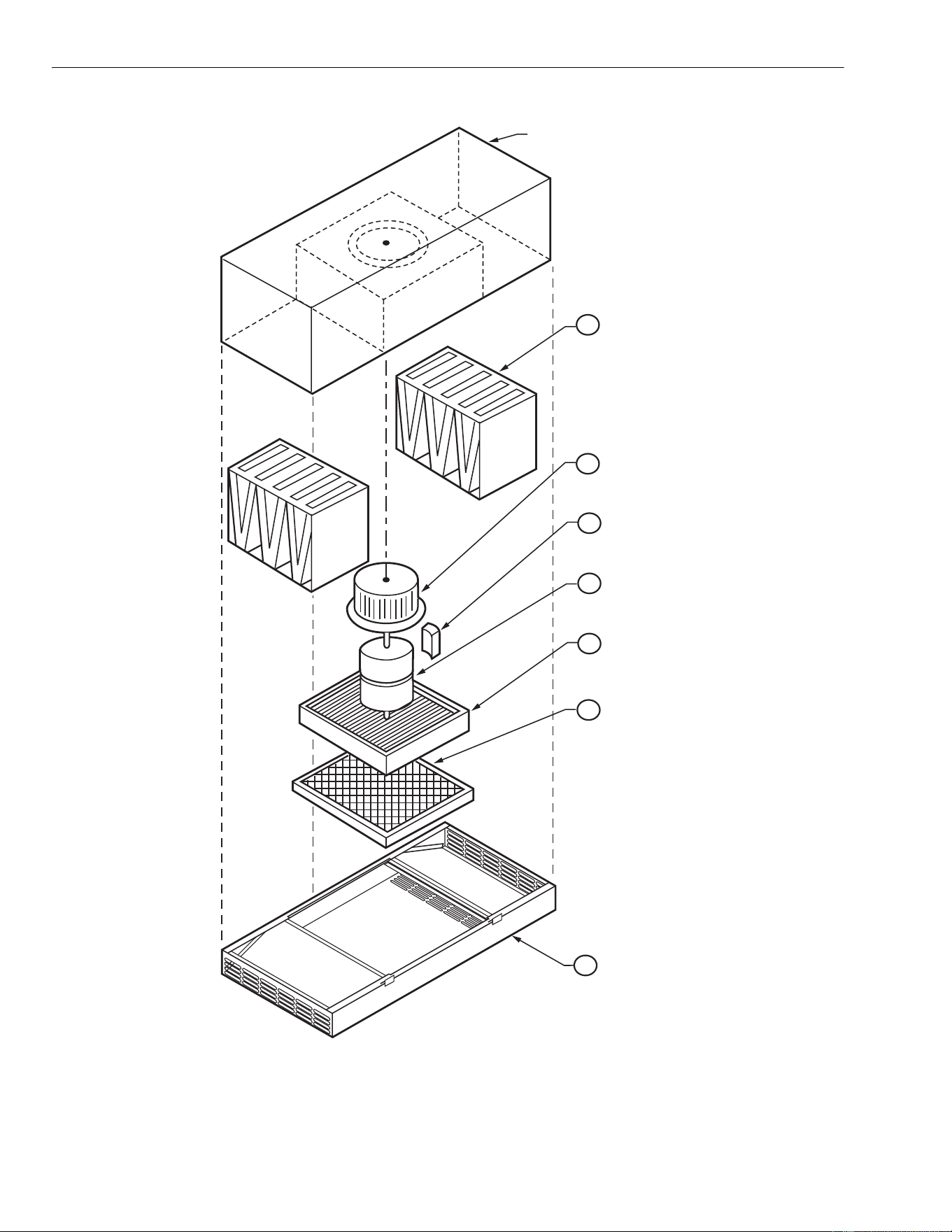
PARTS LIST
Refer to Fig. 9 and Table 5 for replacement part information.
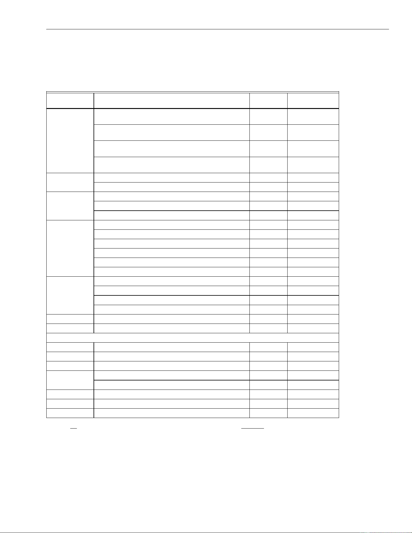
Table 5. Replacement Parts.
Fig.
Reference No. Description Pack Qty Order Number
1 CPZ™ sorbent module (requires 2)—used with only
95% HEPA or 95% ASHRAE particle filters
1 32004078-001
Charcoal sorbent module (requires 2)—used with only
95% HEPA or 95% ASHRAE particle filters
1 32004078-002
Zeolite sorbent module (requires 2)—used with only
95% HEPA or 95% ASHRAE particle filters
1 32004078-003
Permanganate sorbent module (requires 2)—used with
only 95% HEPA or 95% ASHRAE particle filters
1 32004078-004
2 Blower wheel, Series 1 1 32000236
Blower wheel, Series 2, and 3 1 32002285
3 Motor capacitor; 120V, 60 Hz, Series 1,2, and 3 1 32000265
Motor capacitor; 208/230V, 50/60 Hz, Series 1, 2 1 32000549
Motor capacitor; 230V, 50 Hz, Series 3 1 32000265
4 Motor; 120 V, 60 Hz, Series 1 1 32000270
Motor; 208/230V, 50/60 Hz, Series 1 1 32000263
Motor; 120 V, 60 Hz, Series 2 1 32002415-001
Motor; 208/230V, 50/60 Hz, Series 2 1 32002415-002
Motor; 120 V, 3-Speed, 60 Hz, Series 3 1 32002415-004
Motor; 230V, 3-Speed, 50Hz, Series 3 1 32002415-005
5 99.97% HEPA media filter, 3”, Series 1 and 2 1 32000204-001
99.97% HEPA media filter, 4.5”, Series 3 1 32000204-002
95% hospital grade filter 1 32000203
95% ASHRAE particle filter 1 50004739-001
6 Prefilter (disposable) 1 32002307
7 Lid assembly with hinges and latches in White Color 1 32002308-002
OPTIONAL Parts not shown in Fig. 9.
Remote Wall 3-Speed Switch, Series 3 1 190097C
Motor mount bracket 1 32000260
Motor maintenance grommet set 3 32000261
Snap-loc Tabs; Series 1 1 32000262-001
Snap-loc Tabs; Series 2 1 32000262-002
Z Sidemount Bracket Kit 4 32002353
Spring Loaded Plunger 2 32002278
Lid assembly with hinges and latches in Black Color 1 32002308-003
NOTE: All replacement filters must be provided by Air-Pure Systems to maintain U.L. Certification and Warranty.
F111 (SERIES 1,2,3) IN CEILING MEDIA AIR CLEANER
68-0198-2 Revised 5-09 10
CABINET
ASSEMBLY
LID ASSEMBLY WITH
HINGES AND LATCHES
PREFILTER
MEDIA FILTER
MOTOR
MOTOR CAPACITOR
BLOWER WHEEL
SORBENT MEDIA MODULE
(2 REQUIRED)
M11995E
1
6
3
4
5
7
2
Fig. 9. Exploded view of F111 (series 1,2,3) in Ceiling Media Air Cleaner components.

F111 (SERIES 1,2,3) IN CEILING MEDIA AIR CLEANER
11 68-0198-2
NOTES

68-0198-2 Revised 5-09 www.cleanairfacility.com
Air-Pure Systems
16873 Fish Point Rd. SE
Prior Lake, MN 55372-1714
Phone (800) 998-1919
Fax: (800) 221-3248
LIMITED TWO-YEAR WARRANTY
Air-Pure Systems warrants its air cleaner products to be free from defects in workmanship or materials under normal use and service, for a period
of two (2) years from the date of purchase by the original end-user. If at anytime during the warranty period the product is defective or malfunc-
tions, Air-Pure Systems, through the distributor or dealer, from which the product was purchased, or through an authorized warranty repair
station, shall at Air-Pure Systems option, replace or repair the defective product or component.
This warranty does not cover removal or installation costs. This warranty shall not apply if it is shown that the defect or malfunction was caused
by damage which occurred during handling or shipment, improper electrical connections, improper use of the product or abuse.
Air-Pure Systems sole responsibility shall be to repair or replace the product within the terms stated above. AIR-PURE SYSTEMS SHALL NOT
BE LIABLE FOR ANY LOSS OR DAMAGE OF ANY KIND, INCLUDING ANY INCIDENTAL OR CONSEQUENTIAL DAMAGES RESULTING,
DIRECTLY OR INDIRECTLY, FROM ANY BREACH OF WARRANTY, EXPRESS OR IMPLIED, OR ANY OTHER FAILURE OF THIS PROD-
UCT. (Some states do not allow the exclusion or limitation of incidental or consequential damages, so this limitation may not apply to you.) THE
WARRANTIES SET FORTH HEREIN ARE EXCLUSIVE AND AIR-PURE SYSTEMS’ EXPRESSLY DISCLAIMS ALL OTHER WARRANTIES,
WHETHER WRITTEN OR ORAL, IMPLIED OR STATUTORY, INCLUDING BUT NOT LIMITED TO ANY WARRANTIES OF MERCHANTABIL-
ITY, WORKMANSHIP, OR FITNESS FOR A PARTICULAR USE.
This warranty gives you specific legal rights and you may have other rights which vary from state to state.
How to make a warranty claim or have questions answered:
Should you have a warranty claim or questions about the warranty policy, contact the distributor or dealer from which you purchased the product
or the authorized warranty repair stations nearest your location.
NOTE: Do not return any products or parts to the factory without a factory issued “Returned Warranty Goods Label” issued by Air Pure Sys-
tems.
In the event you or other persons, have any questions concerning the use and care of this product or this warranty please call or write the factory.
Air-Pure Systems
16873 Fish Point Rd. SE
Prior Lake, MN 55372-1714
Phone: (800) 998-1919
Fax: (800) 221-3248