Installation Guide
AT-VKP-8E-EU
1
Velocity Keypad
AT-VKP-8E-EU
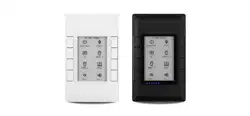
The Atlona AT-VKP-8E-EU is a simple yet powerful 8 button IP-based control system in a
wallplate form factor. The buttons are fully congurable for controls such as display power,
input switching, audio levels, or any other functions supported by system devices. In addition
to Ethernet, the VKP-8E-EU also features RS-232 for control of legacy devices. For enhanced
customization, the VKP-8E-EU incorporates a 2.7” e-ink display that supports multiple pages to
dynamically change icons and text associated with the buttons. LED indicators for each button
and a multi-step LED level indicator provide additional feedback to users. The VKP-8E-EU is
designed to mount in one-gang EU/UK junction boxes and comes with both black and white
faceplates that attach to the button panel via magnets. Power over Ethernet (PoE) provides both
power and data to the panel over a single cable. For setup, the VKP-8E-EU uses a revolutionary
new conguration platform called Atlona Cloud. It provides an intuitive interface for mapping
control commands, text, and icons to buttons using the extensive library of Atlona and third-party
device drivers. When conguration is complete, lightweight instructions can either be sent to the
VKP-8E-EU directly over the network or stored in a le for later upload.
1 x AT-VKP-8E-EU
1 x White faceplate
1 x 3-pin Captive Screw Connector
2 x Mounting screws
2 x Face plate screws
1 x Installation Guide
Package Contents
IMPORTANT: The unit can be set up locally, but the computer used for conguration
must have an external connection.
Installation Guide
AT-VKP-8E-EU
2
http://192.168.0.XXX/local
Must scan QR with mobile
Use share URL function
to open on a computer
<- IoT Mode
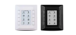
Panel Descriptions
43 5
2
8
6
7
1
1 Control Buttons
Once set up, use the buttons to trigger the
control commands.
2 E-ink Display
Displays the connection and start up
information, along with button icons and
text as set inside cloud conguration
3 Mode Button
During set up, use the bottom left button
to switch between Internet of Things (IoT)
and Local mode.
4 Volume LEDs
LED indicators that display volume level
feedback.
5 Settings Buttons
Press and hold the bottom two buttons to
switch to additional settings options for
the VKP.
6 Button LEDs
These can be set to display multiple
colors within the settings to provide
status.
7 Service Port
This port is used by Technical Support
and is not for users.
8 LAN
Connect an Ethernet cable to this port for
power and control/conguration.
9 RS-232 Port
Connect the included 3-pin captive screw
connector to this port then to the control
device.
Installation Guide
AT-VKP-8E-EU
3
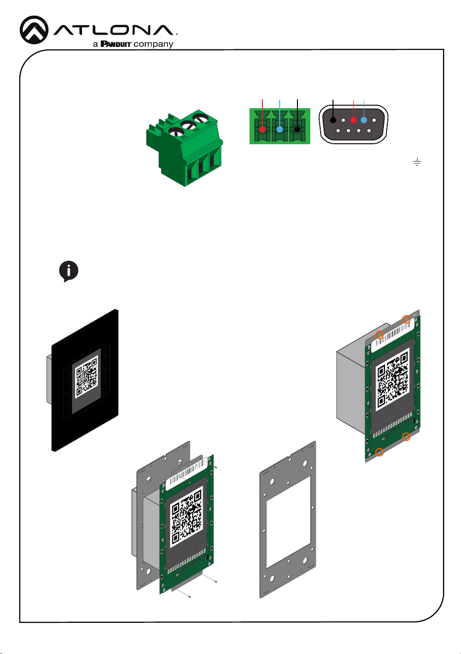
RS-232
A 3-pin captive screw connector has been
included for RS-232.
Pin out will be determined by the RS-232 cable
and connect as RX (receive), TX (transmit) and
(Ground).
GND RX
TX
GNDRX TX
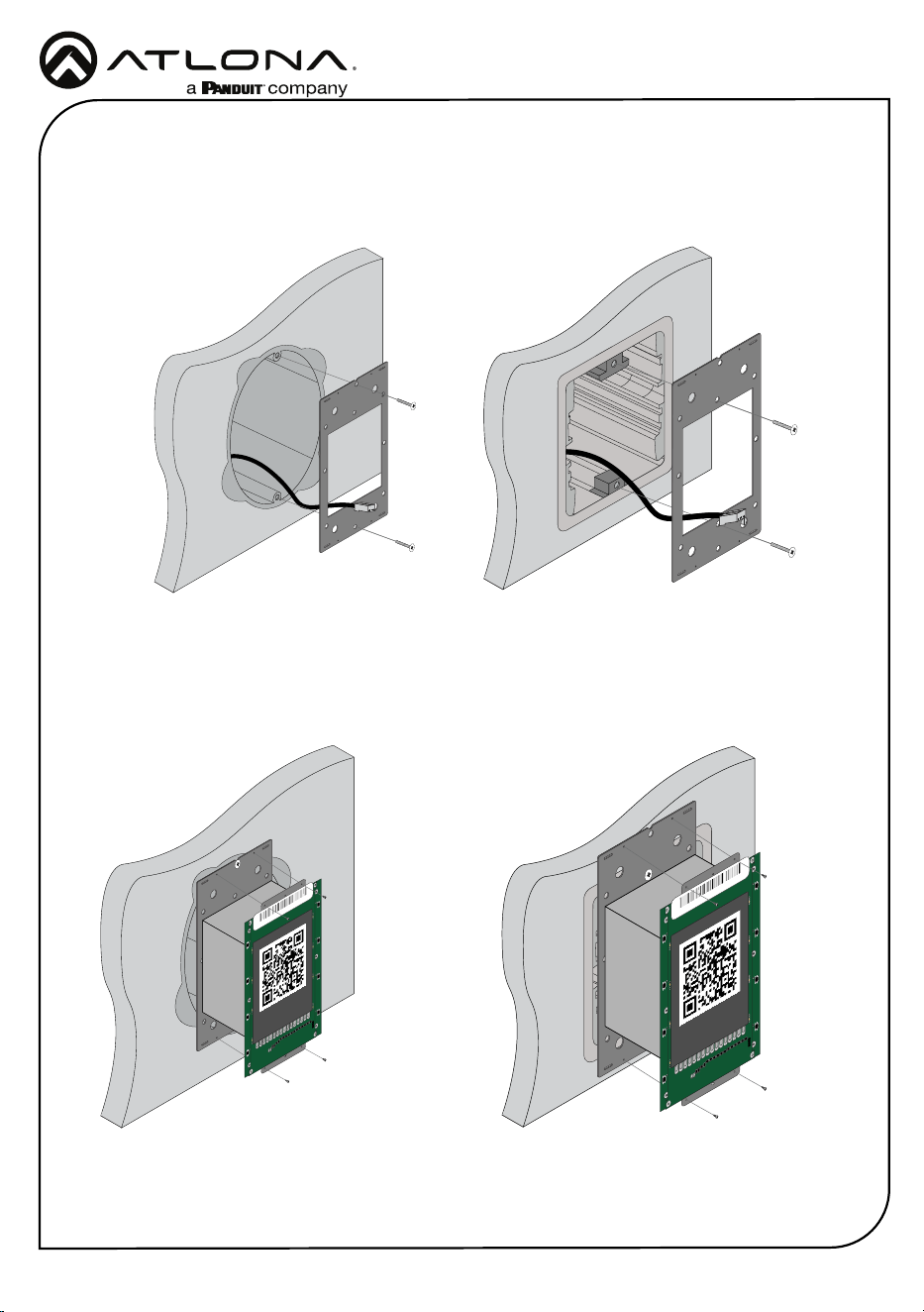
Mounting Instructions
The AT-VKP-8E-EU can be mounted to a 1-gang back box.
1 Select the type of 1-gang back box to use and install into a wall.
2 Thread the Ethernet cable through the 1-gang box.
NOTE: Install using the region’s safety guidelines for electrical boxes.
http://192.168.0.XXX/local
Must scan QR with mobile
Use share URL function
to open on a computer
<- IoT Mode
R6
R5
R7
C1
C2
D28
D27
D26
D24
D23
D22
D21
D20
D19
D17
D16
D15
D14
D13
D18
D25
LED20
LED19
LED18
LED17
LED16
LED15
LED14
LED13
LED12
LED11
LED10
LED9
LED8
LED7
LED6
LED5
B8:98:B0:XX:XX:XX
http://192.168.0.XXX/local
Must scan QR with mobile
Use share URL function
to open on a computer
<- IoT Mode
3 *Optional* Run the RS-232 connector and
cable through the wall and back box.
4 Remove the faceplate from the front of the
VKP-8E-EU. The faceplate is attached using
magnets, so simply grab the faceplate from
the sides and pull it o the unit.
5 Remove the four screws from the top and
bottom of the unit (circled to the right) and
pull the mounting plate from the unit (shown
below).
R6
R5
R7
C1
C2
D28
D27
D26
D24
D23
D22
D21
D20
D19
D17
D16
D15
D14
D13
D18
D25
LED20
LED19
LED18
LED17
LED16
LED15
LED14
LED13
LED12
LED11
LED10
LED9
LED8
LED7
LED6
LED5
http://192.168.0.XXX/local
Must scan QR with mobile
Use share URL function
to open on a computer
<- IoT Mode
B8:98:B0:XX:XX:XX
Installation Guide
AT-VKP-8E-EU
4
6 Thread the Ethernet cable through the mounting plate.
7 Install the mounting plate into the wall, using the two of the included mounting screws.
8 Connect the Ethernet cable (and/or *optional* RS-232 connector) to the LAN port (and RS-232
port) on the back of the unit.
9 Install the unit into the back box, securing it using the 4 screws removed earlier through the
4 holes in the unit and mounting plate.
R6
R5
R7
C1
C2
D28
D27
D26
D24
D23
D22
D21
D20
D19
D17
D16
D15
D14
D13
D18
D25
LED20
LED19
LED18
LED17
LED16
LED15
LED14
LED13
LED12
LED11
LED10
LED9
LED8
LED7
LED6
LED5
B8:98:B0:XX:XX:XX
http://192.168.0.XXX/local
Must scan QR with mobile
Use share URL function
to open on a computer
<- IoT Mode
R6
R5
R7
C1
C2
D28
D27
D26
D24
D23
D22
D21
D20
D19
D17
D16
D15
D14
D13
D18
D25
LED20
LED19
LED18
LED17
LED16
LED15
LED14
LED13
LED12
LED11
LED10
LED9
LED8
LED7
LED6
LED5
B8:98:B0:XX:XX:XX
http://192.168.0.XXX/local
Must scan QR with mobile
Use share URL function
to open on a computer
<- IoT Mode
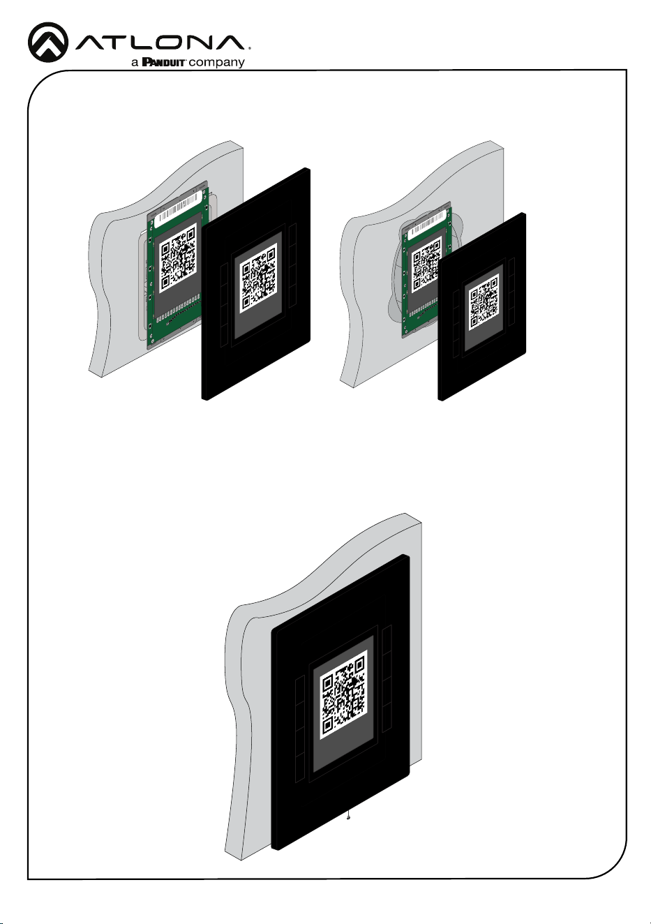
EU - Thread the screws through the top and bottom, as pictured below.
UK - Thread the screws through the middle two screws, as pictured below.
UKEU
Installation Guide
AT-VKP-8E-EU
5
R6
R5
R7
C1
C2
D28
D27
D26
D24
D23
D22
D21
D20
D19
D17
D16
D15
D14
D13
D18
D25
LED20
LED19
LED18
LED17
LED16
LED15
LED14
LED13
LED12
LED11
LED10
LED9
LED8
LED7
LED6
LED5
B8:98:B0:XX:XX:XX
http://192.168.0.XXX/local
Must scan QR with mobile
Use share URL function
to open on a computer
<- IoT Mode
http://192.168.0.XXX/local
Must scan QR with mobile
Use share URL function
to open on a computer
<- IoT Mode
10 Once secured to the wall, place the front face plate back onto the unit. The magnets will
secure it in place.
11 *Optional* To ensure the face plate stays in place, use the included face plate screw and
thread it through the bottom of the face plate (an extra screw is included in case one is lost).
The unit is fully installed.
R6
R5
R7
C1
C2
D28
D27
D26
D24
D23
D22
D21
D20
D19
D17
D16
D15
D14
D13
D18
D25
LED20
LED19
LED18
LED17
LED16
LED15
LED14
LED13
LED12
LED11
LED10
LED9
LED8
LED7
LED6
LED5
B8:98:B0:XX:XX:XX
http://192.168.0.XXX/local
Must scan QR with mobile
Use share URL function
to open on a computer
<- IoT Mode
http://192.168.0.XXX/local
Must scan QR with mobile
Use share URL function
to open on a computer
<- IoT Mode
Installation Guide
AT-VKP-8E-EU
6
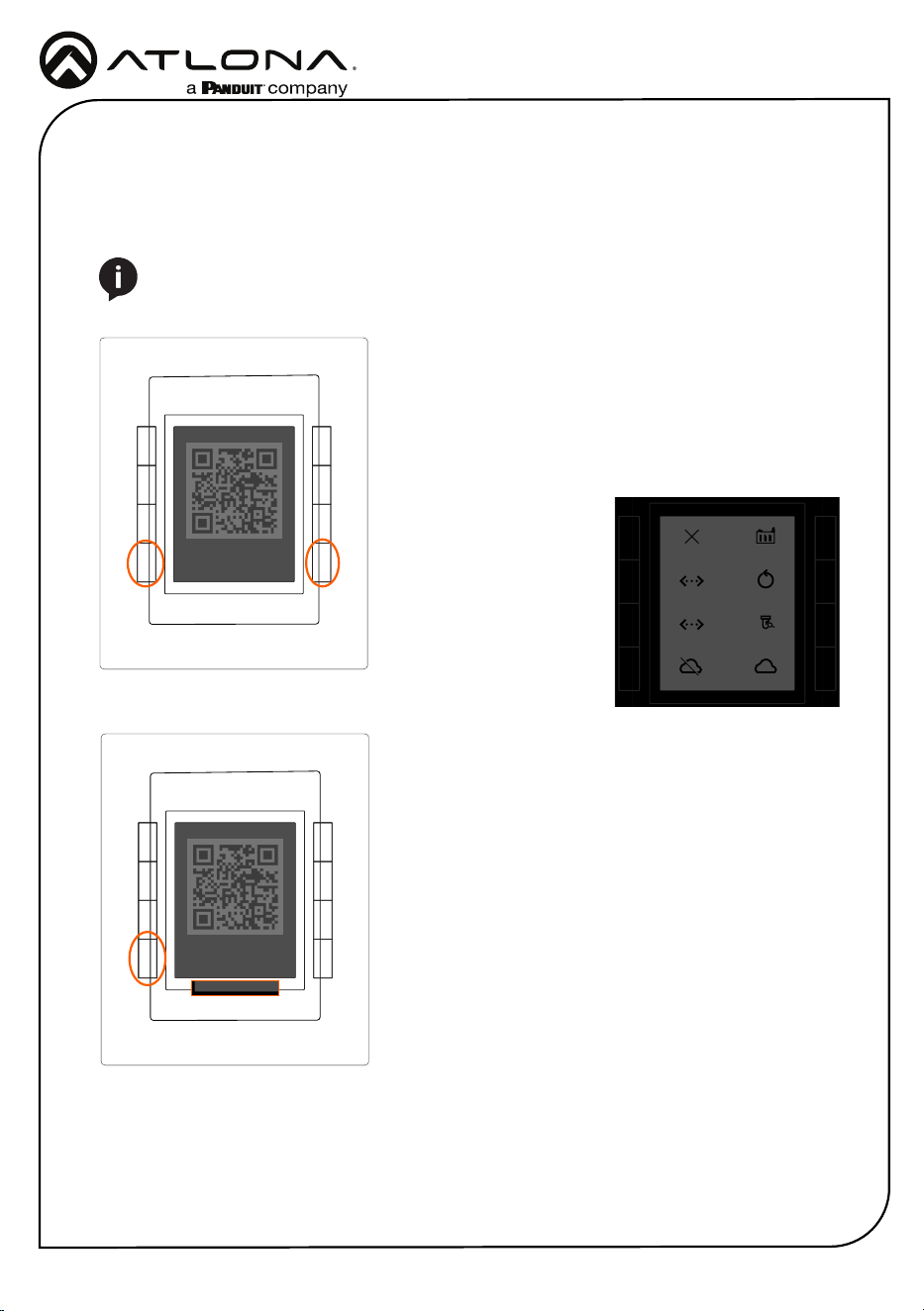
Initial VKP Setup
The AT-VKP-8E-EU has two modes for set up: Local and IoT (Internet of Things - recommended).
No matter which mode is set on the AT-VKP-8E-EU, the computer doing the conguration must
be connected to the Internet.
Local mode will make the local webUI available to do some
basic unit conguration. Scan the QR code or type in the
ip address located at the top of the unit (ex 192.168.0.xxx/
local) to access the webUI of the unit. This will allow for
uploading and downloading conguration les to the unit,
rmware updating, changing network settings, and more.
While local mode allows for basic unit conguration,
control conguration will still need to be done online, with
the cong le being uploaded manually to the unit in the
webUI, rather than synced through the cloud.
Modes can also be switched by pressing the bottom left
hand button from the main screen.
For easy network conguration, press and hold the bottom
left & right buttons for 2 seconds. Once released, it will
open an advanced options screen.
From here, the unit can be changed from DHCP to Static IP
modes by pressing the corresponding buttons to the mode.
It may take 5-10 seconds to switch IPs, the IP will display
at the top. Static IP will set the unit to 192.168.0.231.
The unit can be switched
between Local and IoT Mode
using the bottom buttons,
this will take the unit out of
advanced mode.
The unit can be factory reset
(does not unregister the unit) and
reboot from advanced mode
if needed.
http://192.168.0.XXX/local
Must scan QR with mobile
Use share URL function
to open on a computer
<- IoT Mode
http://192.168.0.XXX/local
Must scan QR with mobile
Use share URL function
to open on a computer
<- Local Mode
Local Mode
NOTE: If the local network is not recognizing or speaking to the unit, ensure that port
443 (https) is enabled. If port 443 is disabled, the unit may not speak correctly across
the network.
Close FacReset
DHCP Test
Local Mode IoT Mode
RebootStatic
192.168.0.XXX
http://192.168.0.XXX/local
Must scan QR with mobile
Use share URL function
to open on a computer
<- IoT Mode
IoT mode sets the unit to be updated through the cloud congurator whenever a change is
made or a rmware update is received.
IoT Mode (recommended)
Installation Guide
AT-VKP-8E-EU
7
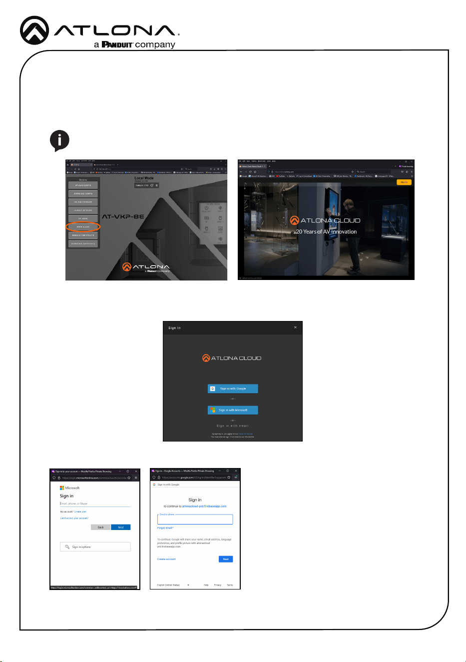
Both modes will have control congured through https://cloud.atlona.com. To get to the
conguration, scan the QR code (when in IoT Mode) on a phone, tablet, etc, type the IP address
of the unit listed at the top of the e-ink display (minus /local in Local Mode), click the Open Cloud
button when in the local webUI (in local mode), or simply enter https://cloud.atlona.com into a
browser. All options will lead to https://cloud.atlona.com.
Once https://cloud.atlona.com page has been opened. It may take a few seconds to load until
the login screen appears. Select the login button in the top right corner of the page. A pop up will
appear.
There are three options to login: Sign in with Google, Sign in with Microsoft, or Sign in with email.
When selecting Google or Microsoft, a
pop up will appear. Enter the account
information and it will send a conrmation
email.
NOTE: The IP address will only redirect if the unit and the PC for conguration are
connected to the same network.
Installation Guide
AT-VKP-8E-EU
8
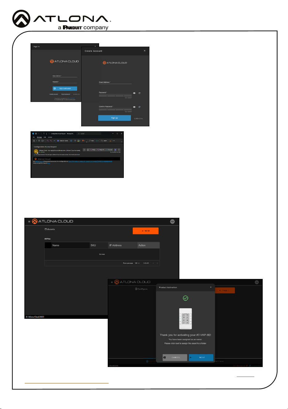
An email will be sent from the address no-reply@
cloud.atlona.com. If it does not appear in the inbox
within 5 minutes, check the Junk/Spam folder.
Select the here link to be redirected to a verify page.
The account is now ready for conguration.
Sign in with email will require an email and
password that has already been set up,
if one has not been created, select the
Create Account link below the blue button,
a new screen will open. Once an email
and password has been added, select
the Sign up button. Once the account has
been created, a conrmation email or text
message will be sent (based on account settings)
to verify the account.
When logging in the rst time, if the unit has internet disabled, it will have a blank conguration
page and the unit will have to be added manually. If the unit is in IoT mode, it will automatically
link and register the unit.
The unit is now ready for conguration. View the manual located in the resource tab of https://
atlona.com/product/at-vkp-8e-eu/ for full instructions on setting up the VKP-8E-EU.
Installation Guide
AT-VKP-8E-EU
9
Version 1
© 2024 Atlona Inc. All rights reserved. “Atlona” and the Atlona logo are registered trademarks of Atlona Inc. All other brand names and trademarks or registered
trademarks are the property of their respective owners. Pricing, specications and availability subject to change without notice. Actual products, product images,
and online product images may vary from images shown here.
US International
atlona.com • 408.962.0515 • 41.43.508.4321
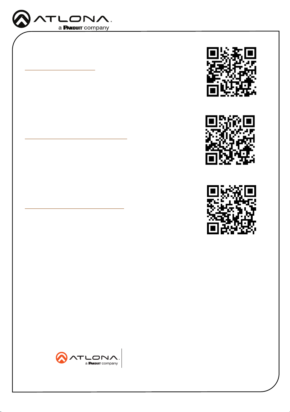
The English version can be found under the resources tab at:
https://atlona.com/product/at-vkp-8e-eu/.
English Declaration of Conformity
Warranty
Chinese Declaration of Conformity 中国RoHS合格声明
To view the product warranty, use the following link or QR code:
https://atlona.com/warranty/.
由SKU列出於:
https://atlona.com/about-us/china-rohs/.
25371-R1