KEF R&D
R Series with MAT
CONTENTS
Introduc�on
Philosophy
R Series with MAT
12
th
Genera�on Uni-Q with MAT for R Series
High Frequency Driver (Tweeter)
Metamaterial Absorp�on Technology
Coupling MAT to the tweeter dome
HF Motor System
Tweeter Gap Damper
Tangerine Waveguide and Shadow Flare
Tweeter THD performance
Midrange Driver
Ultra-low distor�on midrange motor system
Flexible Decoupling Chassis
Midrange suspension
Midrange Cone Neck Decoupler
Midrange THD performance
Low Frequency Drivers
System and Enclosure
Constrained Layer Damping
Damping of standing wave resonances
Bass-reex ports
Crossover
System THD performance
Summary
References
Model Informa�on, Specica�ons and Measurements
2
2
3
4
4
5
5
6
6
7
7
8
8
10
11
12
12
13
13
13
15
17
17
19
19
20
22
₁
Introduc�on
R Series was rst introduced in 2011 as a high-
performance speaker range that benets from the
technology developed for the Reference Series but in a
more aordable package.
R Series, thus, takes on the main acous�c principles of
the modern Reference Series:
• A slim rec�linear cabinet heavily braced with internal
constrained layer damping
• A Uni-Q driver array dedicated to midrange and
high frequency surrounded by a Shadow Flare to
reduce bae edge dirac�on
• A D’Appolito symmetrical array congura�on of low-
frequency drivers around the Uni-Q [1] for a smooth
and symmetrical ver�cal direc�vity in the
oorstanding models and horizontal direc�vity in
the centre channel models
• Rear-ring bass-reex ports with op�mised
posi�ons to minimise the leakage of the enclosure’s
internal standing waves and exible port walls to
damp the ports’ inherent acous�c resonances
These principles provide a solid founda�on for an
acous�cal system that can deliver music reproduc�on
with extremely low coloura�on and a smooth o-axis
response in all direc�ons, allowing it to work well in a
wide variety of rooms.
In its second itera�on in 2018, R Series further became
a vessel of innova�ve technology development,
introducing the rst 12�� genera�on Uni-Q featuring the
Tweeter Gap Damper.
'Meta’
R Series with MAT is the sixth model range to be
launched by KEF since 2020 (LS50 Collec�on, Blade and
The Reference with MAT, LS60 Wireless and
Ci250RRM-THX) to incorporate MAT (Metamaterial
Absorp�on Technology).
KEF’s MAT is employed as an acous�c absorber behind
the tweeter diaphragm and is the main technology
improvement featured in the new R Series. Every
speaker in the range thus carries the moniker ‘Meta’ in
its name.
‘Meta,’ nonetheless, reects much more than the
applica�on of MAT. It implies a full research and
development project has been undertaken to redesign
all cri�cal components in the speaker systems to achieve
a considerable leap forward in performance. This is now
what has come to be expected from any KEF speaker
with ‘Meta’ in its name and R Series is no excep�on.
Philosophy
“Of all art, music is the most indenable and the most
expressive, the most insubstan�al and the most immediate,
the most transitory and the most imperishable.Transformed
to a dance of electrons along a wire, its ghost lives on. When
KEF returns music to its righ�ul habitua�on, your ears and
mind, they aim to do so in the most natural way they can...
without drama, without exaggera�on, without ar�ce.”
Raymond Cooke OBE, KEF Founder
Loudspeakers are the nal stage in the sound
reproduc�on chain. It is down to the loudspeaker to
generate the sound that the listener will hear. While
other pieces of audio equipment have clearly dened
roles, and it is easier to outline how they would ideally
perform, the ideal loudspeaker is more dicult to dene.
It is simpler to rst consider what the complete audio
system is trying to achieve. The ideal audio system
should be able to recreate a live sonic event so that it is
indis�nguishable from the original. The listeners should
be transported to the environment of the live event.
They should be convinced that they are si�ng in the
actual concert hall in which the live event occurred. They
should experience the acous�cs of the space, perceive
the loca�ons of the instruments, interact with the space,
and hear the change in the sound as they turn their
heads towards the soloist.
Many recordings are available that never existed as live
events. For example, a rock band captured in a studio or
music with synthesised instruments. Nevertheless, the
same objec�ve applies for these situa�ons: the sonic
event that we wish to hear is the one that was envisaged
by the musicians and producers. For this to be achieved,
there are implica�ons for the delity of the replay
system: it must not colour the sound with the
introduc�on of distor�on or dynamic range
compressions; it must have a neutral �mbral character,
without resonance or imbalance; it should have a good
temporal resolu�on such that it does not “smear” the
sonic event. Each of these delity requirements provide
clear targets for the loudspeaker designer.
However, this ideal audio system has two further
implica�ons that are more dicult to handle. Firstly, the
spa�al informa�on of the original event should be
captured and replayed. Secondly, the listeners should
hear only the acous�c space of the original event and
not the acous�c space in which they are located.
Technically, neither stereo nor conven�onal
mul�channel playback are sucient to recreate the
exact sound eld of an event. However, our percep�on
is not exact: our auditory system builds a scene in our
mind based on cues in the signals reaching our ears.
Cues such as the rela�ve arrival �me and level of the
sound at each of our ears. Stereo playback provides a
simple means by which the ar�st or recordist may
communicate these cues to the listener. The listener
builds a picture of the sonic event in their mind and
emo�onally connects with the experience of listening to
the original.
Loudspeakers must be designed to maximise the
communica�on of these spa�al cues. To do this, a
loudspeaker must have a response that does not change
rapidly with direc�on. An irregular direc�vity can result
in the loudspeaker communica�ng spa�al cues that
conict with those in the recording.
Controlling the loudspeakers’ direc�vity is also key to
avoiding loss of midrange and treble delity, which can
happen when loudspeakers are placed in a real listening
environment. One of the features of our auditory
percep�on is that we are well used to hearing sounds
that include reec�ons o close surfaces. Our auditory
system can iden�fy the direct sound and separate out
reec�ons to the extent that we do not perceive the
early reec�ons as separate events. The listener will
a�ribute any �mbral imbalance in the reec�ons to the
original source. This means that loudspeakers must have
a frequency response that is good in all direc�ons, not
simply in the direct path to the listener. Loudspeakers
must have a smooth and balanced frequency response
on-axis and in other direc�ons. If this is achieved, the
listeners will be able to “hear through” the room in which
they are located and perceive the acous�c space
captured in the recorded sound.
In summary, loudspeakers must be designed to have a
smooth and balanced response both in terms of
frequency and space. The sound from loudspeakers
should emanate from the drivers themselves and not
from other components, such as resona�ng panels or
openings. The drivers should operate in a well-
controlled manner throughout and beyond their band.
Loudspeakers should have low distor�on and
compression and a good temporal response.
R Series with MAT
The development of the new R Series with MAT began
with the design of a new Uni-Q, which belongs to the
family of KEF’s 12�� genera�on Uni-Q driver arrays. This
Uni-Q directly benets from the research carried out
during the development of the high-performance Uni-Q
for the Blade and Reference Meta.
Integra�ng this new Uni-Q into the speakers prompted
the redesign of key system components, including new
crossover lters that benet from new and extended
Figure 1. 12
th
Genera�on Uni-Q with MAT for R Series
2 3
measurement and simula�on tools developed for LS50
Meta, Blade Meta, and Reference Meta.
Furthermore, many of KEF’s technologies present in R
Series with MAT have been carried over from R Series
2018 [2]:
• Tweeter Gap Damper
• Tangerine Waveguide and Tangerine Waveguide
S�ening Ribs
• S�ened Tweeter Dome
• Uni-Q Shadow Flare
• Midrange Cone Neck Decoupler
• Low frequency drive units with hybrid aluminium
diaphragm and low-distor�on motor
• Flexible Wall ports
• Cabinet bracing with Constrained Layer Damping
The result is a range of seven speaker models that
reproduce music in a cleaner, more natural, and more
realis�c way, and which be�er interact with typical
listening rooms to recreate a more holographic stereo
image from a recording.
The range consists of three oorstanding models (R11
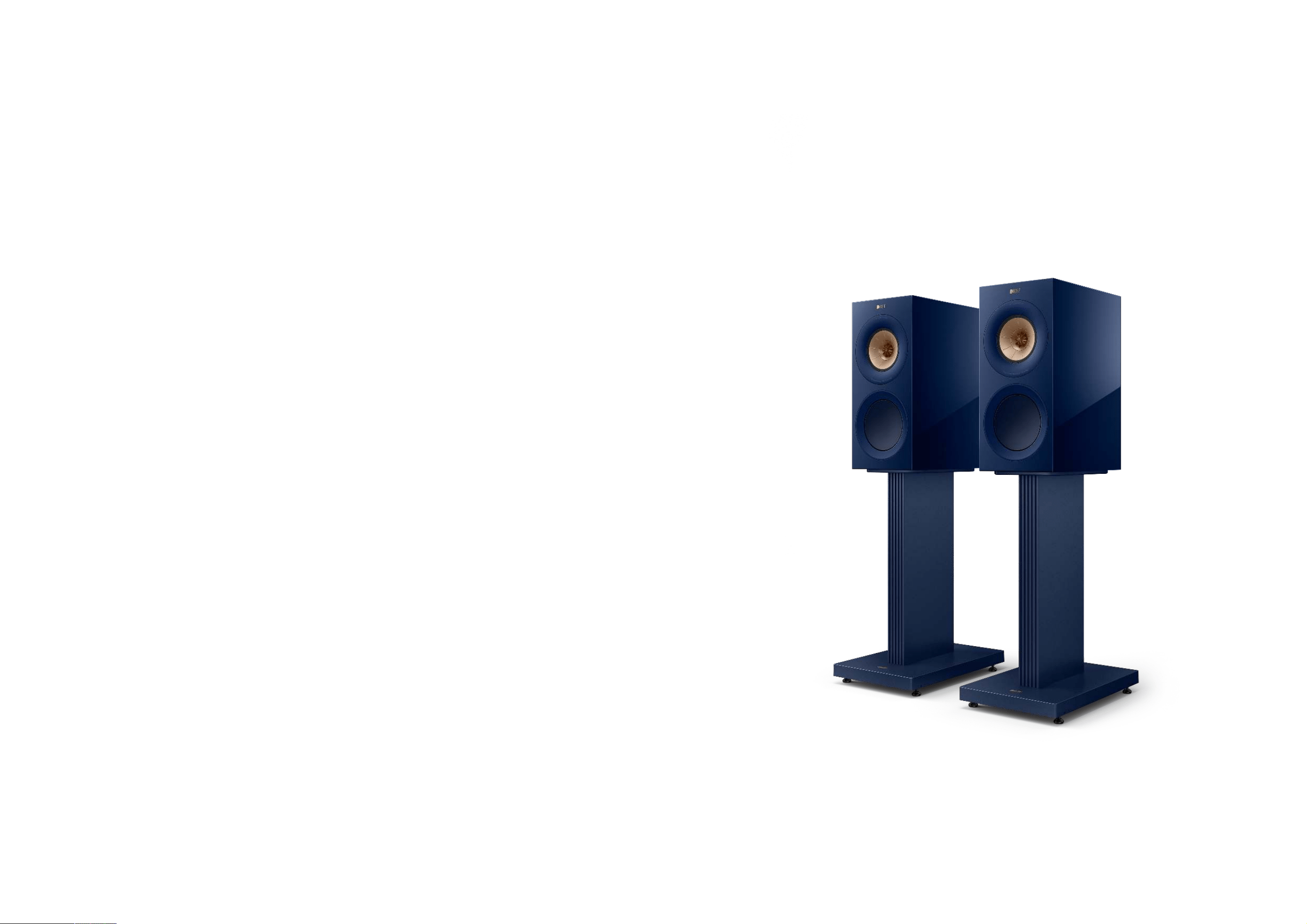
Meta, R7 Meta, R5 Meta), one standmount model (R3
Meta), two LCR models (R6 Meta, R2 Meta) and one
Dolby Atmos® cer�ed model (R8 Meta). Addi�onally,
the new S3 stand is now oered for the R3 Meta
standmount speaker.
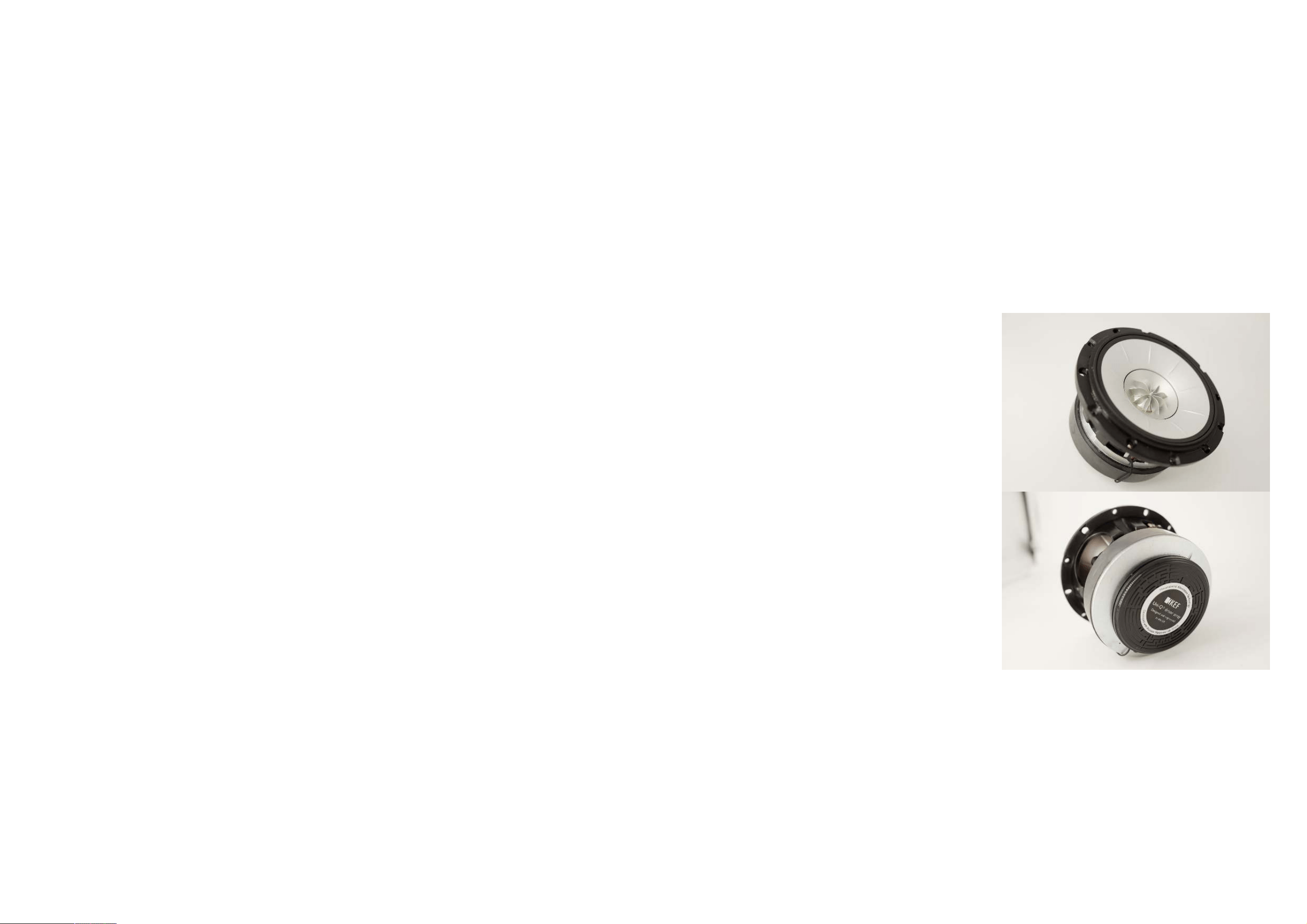
12
th
Genera�on Uni-Q with
MAT for R Series
In this itera�on, the Uni-Q driver array incorporates a
new tweeter and tweeter motor with MAT, a completely
new midrange motor with a low-distor�on, split top
plate design, KEF’s unique Flexible Decoupling Chassis
and a smaller higher-excursion suspension for the
midrange driver (Figure 2). More informa�on on the
fundamental concepts underpinning the Uni-Q
arrangement can be found in the 2014 Reference White
Paper [1].
High Frequency Driver
(Tweeter)
The tweeter in the new Uni-Q contains a unique
technology package that deals with the front and rear
sound produced by the dome in a way that no other
manufacturer does.
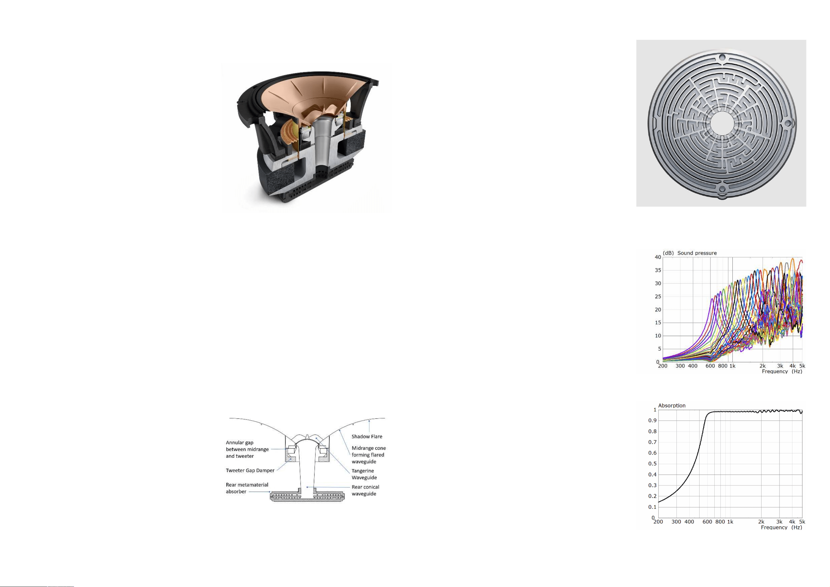
Figure 3 shows a simplied sec�on view of the tweeter’s
acous�cal system. The front of the s�ened aluminium
dome radiates into a small compression chamber loaded
by the Tangerine Waveguide, a sophis�cated waveguide
and phase-plug geometry that works together with the
spherical prole of the dome to help it radiate more like
a true pulsa�ng sphere at high frequencies, where
pistonic domes become considerably direc�onal [3]. This
waveguide smoothly ares out onto the enclosure bae
using the midrange cone as a part of its prole. An outer
trim, the Shadow Flare, con�nues this waveguide and
terminates it smoothly, while recessing the Uni-Q from
the front bae, eec�vely ‘shadowing’ the bae edges
from the tweeter output and virtually smoothing the
edges of the cabinet. This carefully op�mised geometry
ensures the front sound waves from the dome
propagate evenly into the listening room with a wide and
smooth direc�vity.
The rear surface of the dome radiates sound directly into
a wide conical waveguide that is acous�cally terminated
by the acous�c metamaterial absorber, where it is
absorbed almost completely.
Between the tweeter and midrange voice coil an annular
gap is formed to allow the free movement of the la�er.
This gap creates an undesirable resonator. The Tweeter
Gap Damper resides inside a tuned cavity behind the
tweeter and is coupled to this gap to reduce the
resonance by providing absorp�on.
Metamaterial Absorp�on
Technology
Metamaterial Absorp�on Technology (MAT) is the name
given to a metamaterial absorber disc that is acous�cally
coupled to the rear of the tweeter dome. Its func�on is
to absorb the rear sound waves radiated by the tweeter
dome which would otherwise be a source of distor�on
when reected back into the dome.
This disc comprises 30 channels of diering lengths,
formed into tubes, sharing an opening at the centre of
the disc (Figure 4). The tubes act as quarter-wavelength
resonators or absorbers, each tuned to a dierent
frequency with a high Q, which eec�vely absorb a
narrow frequency band and its harmonics (Figure 5). The
absorp�on of these channels is tuned to overlap in
frequency, leading to almost complete absorp�on across
the spectrum above 620Hz - well below the lower
threshold of the tweeter’s working bandwidth (Figure 6).
At 11mm deep, its performance is comparable to a well-
designed tapered tube absorber measuring 50cm long.
This allows its inclusion into loudspeakers of any size,
without taking up signicant space in the cabinet [4][5].
Coupling MAT to the tweeter dome
Of equal importance to the applica�on of MAT is how
the back wave is directed into the absorber. This
requires a large waveguide opening through the middle
of the midrange motor stretching from the back of the
tweeter dome to the rear of the midrange motor, where
the absorber disc is situated.
The conical waveguide’s length, angle and opening
diameters on both ends are specic to this new Uni-Q
since the acous�c impedance of the waveguide must
match that of the opening of the tweeter absorber to
avoid a reec�on of the wave back into the tweeter
dome.
Figure 2. Cutaway of the 12
th
Genera�on Uni-Q with MAT for R Series
Figure 3. Simplied view of the tweeter’s acous�cal system
Figure 4. Metamaterial Absorp�on Technology
Figure 5. Pressure response at closed end of each absorp�on channel
Figure 6. Absorp�on at the entrance of the conical duct, immediately behind the
dome
4 5
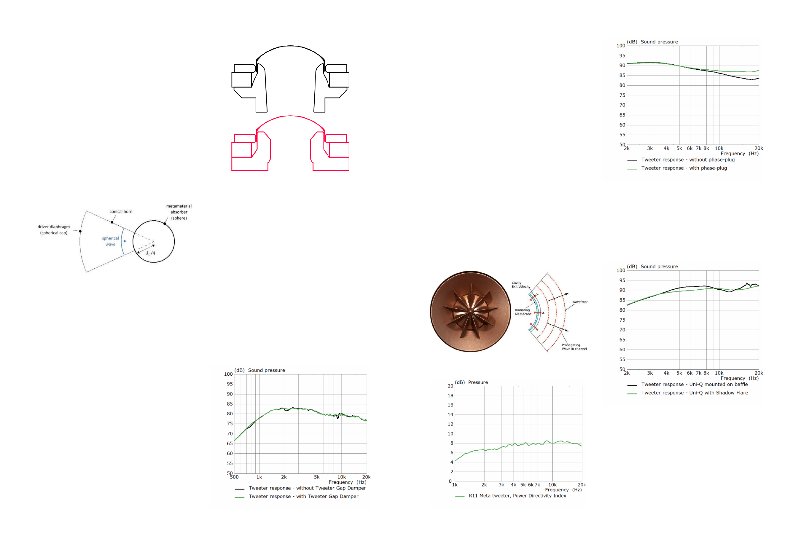
This waveguide is a tapered duct with a conical prole,
which reduces in diameter towards the absorber’s
opening. A detailed explana�on and the mathema�cs
behind MAT and its coupling to the tweeter dome can be
found in the original Audio Engineering Society scien�c
paper [4].
Figure 7 shows a diagram describing the geometric
rela�onship between the spherical dome tweeter, the
conical waveguide, the aperture angle to the
metamaterial absorber and the absorber’s length related
to one quarter of the wavelength of its cut-on
frequency. The principle being that a spherical wave
travelling along a conical horn will avoid reec�on at the
horn-absorber interface if the interface radius is equal to
a quarter of a wavelength of the metamaterial cut-on
frequency.
This arrangement further allows for an easier
accommoda�on of the absorber into the driver package
and reduces the size of the MAT disc itself. In addi�on,
the increase of acous�c volume behind the tweeter due
to the presence of the waveguide reduces non-linear
distor�on associated to the spring eect of compressing
the air in this cavity.
HF Motor System
The tweeter motor vent hole, forming a part of the
conical waveguide that couples the tweeter dome to the
metamaterial absorber, has been maximised to allow the
rear sound wave to travel as freely as possible. This
required the design of a new motor with a Neodymium
magnet and a steel geometry op�mised to oer a high
force factor to maintain the tweeter sensi�vity and high
steel magne�c satura�on to reduce distor�on due to
magne�c hysteresis.
Figure 8 shows a comparison of the new geometry with
the previous design where the increased rear vent area
is clear.
Tweeter Gap Damper
The Tweeter Gap Damper has been redesigned to t
between the midrange and tweeter motors (Figure 3)
following the same approach as the Blade and Reference
Meta Uni-Q.
The gap that forms between the tweeter waveguide and
the midrange cone extends down to the midrange motor
and acts like an organ-pipe resonator that is excited by
the output of the tweeter, aec�ng its response. The
Tweeter Gap Damper expands this annular gap into an
acous�c cavity that works as a tuned Helmholtz
resonator and then adds acous�c damping to control its
resonance. This way the resonance is dissipated and its
eect on the tweeter response is reduced (Figure 9).
Tangerine Waveguide and Shadow
Flare
The Tangerine Waveguide, midrange cone, and Shadow
Flare together form a smooth axi-symmetric waveguide
that is designed to propagate spherical sound waves
from the tweeter into the listening room in a controlled
way [6].
However, due to its pistonic mo�on, the spherical
tweeter dome does not produce an even, normal surface
velocity across its en�re surface. To overcome this, the
Tangerine Waveguide works as a phase plug that creates
a small, low-compression chamber in front of the dome,
allowing it to radiate through nine computer-op�mised
radial channels. It transforms the axial air par�cle mo�on
near the diaphragm into a close approxima�on of a true
pulsa�ng sphere at the end of its ns (Figure 10). The
result is a wide and close to constant direc�vity pa�ern
for the tweeter at high frequencies (Figure 11).
Furthermore, the compression chamber has the
secondary eect of boos�ng the tweeter sensi�vity
from around 7kHz upwards (Figure 12).
The Shadow Flare further controls the direc�vity of the
tweeter and recedes the Uni-Q into the enclosure by
5mm, enough to create an acous�c shadow at the bae
edges closest to the driver. The result is a substan�al
reduc�on in frequency response ripple of both midrange
and tweeter (Figure 13).
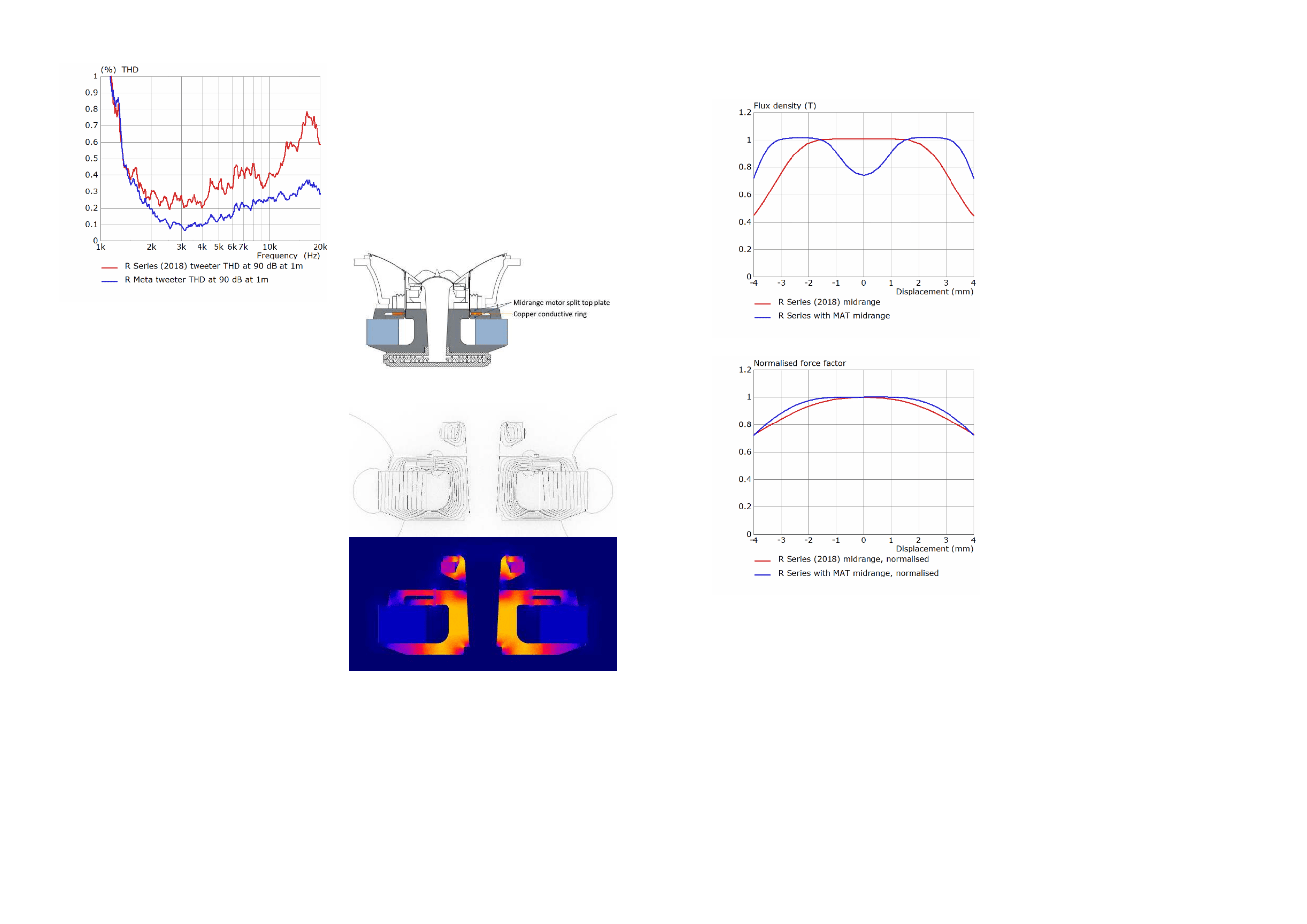
Tweeter THD Performance
Figure 14 shows a comparison of THD (%) between the
2018 R Series tweeter and the R Series with MAT
tweeter. For this measurement, the same second-order
high-pass crossover with a cut-o frequency of 2 kHz
has been used to protect the tweeters from damage and
to keep their output constant around 90dB at 1m up to
20kHz. Both tweeters have been measured in an R11
enclosure.
Figure 10. Tangerine Waveguide geometry
Figure 12. Eect of the Tangerine Waveguide compression chamber on the
tweeter’s axial response
Figure 9. Improvement in tweeter frequency response due to the Tweeter Gap
Damper
Figure 8. Comparison of tweeter motor geometries for R Series (2018) (red, bo�om)
and R Series with MAT (black, top)
Figure 7. Geometric principle behind the coupling of the tweeter spherical dome to
the metamaterial absorber
Figure 11. Tweeter Power Direc�vity Index (without crossover) as measured on
R11 Meta
Figure 13. Comparison of Uni-Q driver HF response with and without Shadow
Flare
6 7
Midrange Driver
Ultra-low distor�on midrange motor
system
The new midrange motor is closely based on the one
developed for Blade and Reference Meta. It has been
specically designed to eliminate force factor
modula�on with displacement, minimise voice coil
inductance magnitude and minimise inductance
modula�on with displacement. These are the primary
factors responsible for midrange harmonic and
intermodula�on distor�on.
The motor top plate is an unconven�onal design
consis�ng of two sec�ons separated by an air gap. A
short voice coil moving within forms an underhung
arrangement. Inside the gap, and slightly indented, sits a
copper ring which is aligned with the centre of the voice
coil.
The motor pole also now accommodates the tweeter
rear waveguide inside it as well as the Tweeter Gap
Damper above it. Figure 15 shows a sec�on view of the
Uni-Q highligh�ng the midrange motor system and its
split top plate design.
Figure 16 shows the magne�c circuit of the Uni-Q
midrange and tweeter motors. The behaviour of the
magne�c ux at the split top gap is observable.
The motor force factor BL is the product of the ux
density B of the magne�c eld crossing the voice coil
gap, and the voice coil length L immersed in that
magne�c eld. BL is a func�on of the voice coil’s
displacement. Typically, as the voice coil moves away
from the gap, BL decreases as the length of coil present
in the gap is reduced. This modulates the force applied
to the voice coil and thus distorts the signal being
reproduced. This is one of the main sources of harmonic
distor�on in drivers.
The new split top plate design focuses the magne�c ux
available from the motor’s ferrite magnet away from the
centre of the voice coil towards its ends. This creates an
M-shaped magne�c ux density prole B(x) that
decreases around the voice coil’s rest posi�on (Figure
17).
The resul�ng BL(x) is thus a�er along the voice coil’s
excursion of +/- 2mm compared to the previous motor
(Figure 18). A a�er BL(x) means the force applied to the
voice coil will more closely follow the applied signal as
the voice coil moves from its res�ng posi�on.
As AC current ows through the voice coil, an
alterna�ng magne�c eld is produced. Its strength
depends on the inductance of the voice coil, with higher
inductance producing a stronger eld. This AC magne�c
eld is conducted by the steel in the motor system and
superimposed on the DC eld produced by the
permanent magnet.
Steel is highly magne�cally non-linear, and the
superimposed AC magne�c eld causes some of the
magne�c domains within the steel to reorient. This
results in a shi� in the permeability of the steel, leading
to modula�on of the DC magne�c eld, and a
modula�on of the motor BL. These sudden shi�s in the
magne�c domains are also picked up as induced voltage
signals in the voice coil, corrup�ng the music signal. This
behaviour is highly hystere�c, and the generated
distor�on has a par�cularly unpleasant characteris�c.
This is not the only issue, however. Inductance itself
varies with the posi�on of the voice coil - where the
voice coil is constantly being pulled towards where
inductance is highest. This is known as ‘reluctance force’
and is highly non-linear as it is propor�onal to the square
of the current owing through the voice coil.
To address these issues, the motor geometry has been
op�mised to increase satura�on of the steelwork to
reduce its magne�c permeability, thus decreasing its
suscep�bility to be magne�sed by the voice coil’s AC
magne�c eld.
The wide copper insert placed within the air gap created
by the split top plate works as a conduc�ve region and it
couples to the voice coil allowing the ow of induced
current through it. This produces an opposing magne�c
eld to the one created by the voice coil, further
reducing the ability of the voice coil to magne�se the
motor steel.
This arrangement is par�cularly advantageous. Si�ng
right in the middle of the two top plate sec�ons and
aligned with the voice coil’s centre along its length, the
conduc�ve copper ring’s eect on lowering distor�on is
much greater, and symmetrical with displacement.
Finally, an added benet of the copper ring being so
close to the voice coil is that it eciently dissipates heat
away from it. This reduces thermal compression of the
signal whilst improving eciency.
Figure 19 shows a visualisa�on of the ux density
modula�on regions present in the steelwork of the
motor near the voice coil gap at 500Hz, a representa�ve
frequency in the midrange. A considerable reduc�on can
be observed when the op�mised conduc�ve region of
copper is added to the motor.
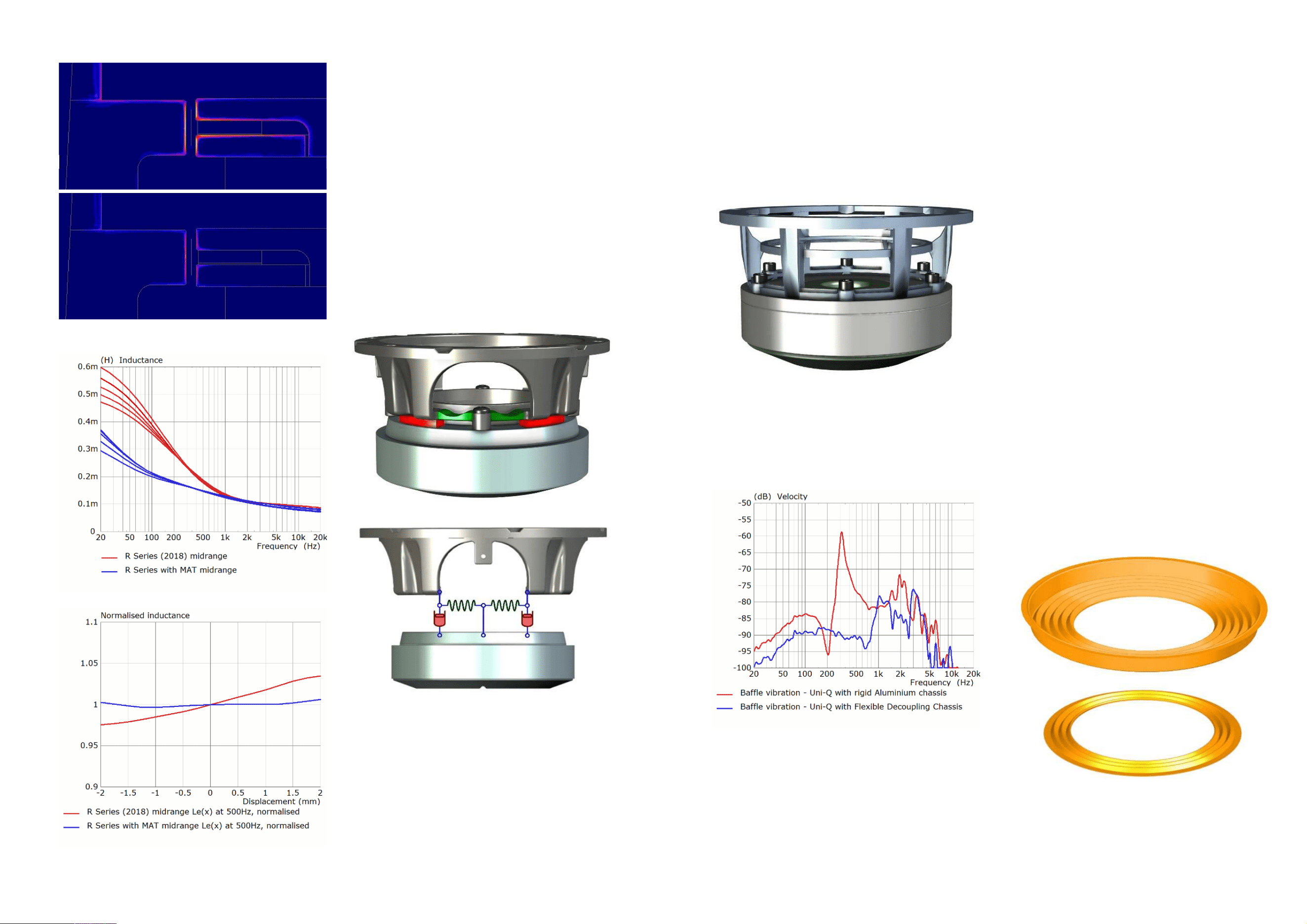
Figure 20 shows a comparison for the previous and new
motors of the voice coil inductance across frequency for
several voice coil posi�ons ranging along +/-2mm where
the reduc�on in inductance modula�on with
displacement is observable.
Taking a slice of Figure 20 at 500Hz reveals that
inductance modula�on is almost eliminated across voice
coil displacement (Figure 21).
Figure 18. Midrange motor force factor BL(x) normalised to 0mm displacement
Figure 17. Midrange motor ux density B(x)
Figure 15. Detail of the midrange motor within the Uni-Q
Figure 16. Uni-Q motor system magne�c circuit. Magne�c eld lines (top) and ux
isovalues (bo�om)
8 9
Figure 14. Comparison of the tweeter measured THD (%) between R Series (2018)
(red) and R Series with MAT (blue) as measured in an R11 enclosure at 90 dB SPL at
1m with the same second-order high-pass crossover with a cut-o frequency of
2kHz
Flexible Decoupling Chassis
Another technology directly carried over from Blade and
Reference Meta is KEF’s Flexible Decoupling Chassis.
The new Uni-Q chassis is constructed of a composite
material. While its outer rim is directly a�ached to the
front bae through a s� steel plate, the chassis legs
incorporate eight exible spring elements connec�ng
the rigid por�on of the structure to the midrange motor.
In parallel to the exible spring elements a set of four
damping material pads provide mechanical damping to
the springs. Figure 22 shows this arrangement together
with a diagramma�c representa�on of the mechanism
involved in the decoupling.
In comparison, Figure 23 shows the previous design
from R Series (2018), where the aluminium chassis is
bolted directly onto the midrange motor.
When the mass of the midrange motor vibrates when
excited by the reac�ve force from the moving voice coil,
this vibra�on is ‘decoupled’ or disconnected from the
enclosure by the exible spring elements and quickly
dissipated by the damping pads. The result is the motor
vibra�on cannot leak into the cabinet and be re-radiated
as sound into the listening room. Furthermore, the back
of the Uni-Q, previously anchored to the rear wall of its
own enclosure through a damping pad, is no longer
connected to it in order to allow the decoupling chassis
to work as intended.
A more detailed descrip�on of driver decoupling
approaches can be found in the Blade and Reference
Meta white paper [7].
Figure 24 shows a comparison of the rigid chassis and
the exible decoupling chassis performance through a
point velocity measurement made with a laser
vibrometer on a speaker bae when the midrange driver
is excited by a sine sweep. In the case of the rigid
chassis, the measurement clearly shows the motor mass
resonance, around 310Hz, has leaked onto the bae.
This leads to the bae radia�ng this as sound. In
contrast, in the case of the Flexible Decoupling Chassis,
the measurement shows no trace of the motor mass
resonance leaking to the bae, having been reduced by
more than 30dB.
Midrange suspension
The suspension centres the voice coil in the magne�c
gap and provides a high restoring force that protects the
voice coil from damage at extreme displacements.
A large suspension with more rolls allows a greater range
of mo�on, which is essen�al for high performance low
frequency drivers. However, large suspensions suer
from mechanical resonance within the driver passband.
When this happens, a glitch or dip forms in the driver’s
frequency response, which is undesirable and easy to
perceive as the ear is most sensi�ve in the midrange
frequency region.
Shi�ing the suspension’s resonance out of the midrange
opera�ng frequency band is challenging since it requires
a very low mass while s�ll allowing the driver to move its
full linear excursion.
The suspension prole (Figure 25) has been redesigned
to reduce its width to 0.69cm (0.27”), which has the
eect of decreasing its mass and increasing its resonant
frequency out of the passband while s�ll allowing a
linear excursion of more than +/- 2mm.
Figure 26 shows a comparison of the FEA-simulated
frequency response of the 2018 R Series midrange
Figure 25. Compara�ve view of midrange suspensions. R Series (2018) (top) and R
Series with MAT (bo�om)
Figure 21. Comparison of normalised midrange voice coil inductance modula�on
with displacement at 500Hz
Figure 24. Eect of the Flexible Decoupling Chassis on bae vibra�on
Figure 20. Comparison of midrange voice coil inductance modula�on with
displacement
Figure 23. R Series (2018) Uni-Q rigid aluminium chassis directly axed to motor
Figure 22. R Series with MAT Uni-Q Flexible Decoupling Chassis (top) and
diagramma�c representa�on (bo�om) showing the exible spring elements
highlighted in green and damping material highlighted in red
10 11
Figure 19. Midrange motor ux density modula�on at 500Hz without (top) and with
copper conduc�ve region (bo�om)
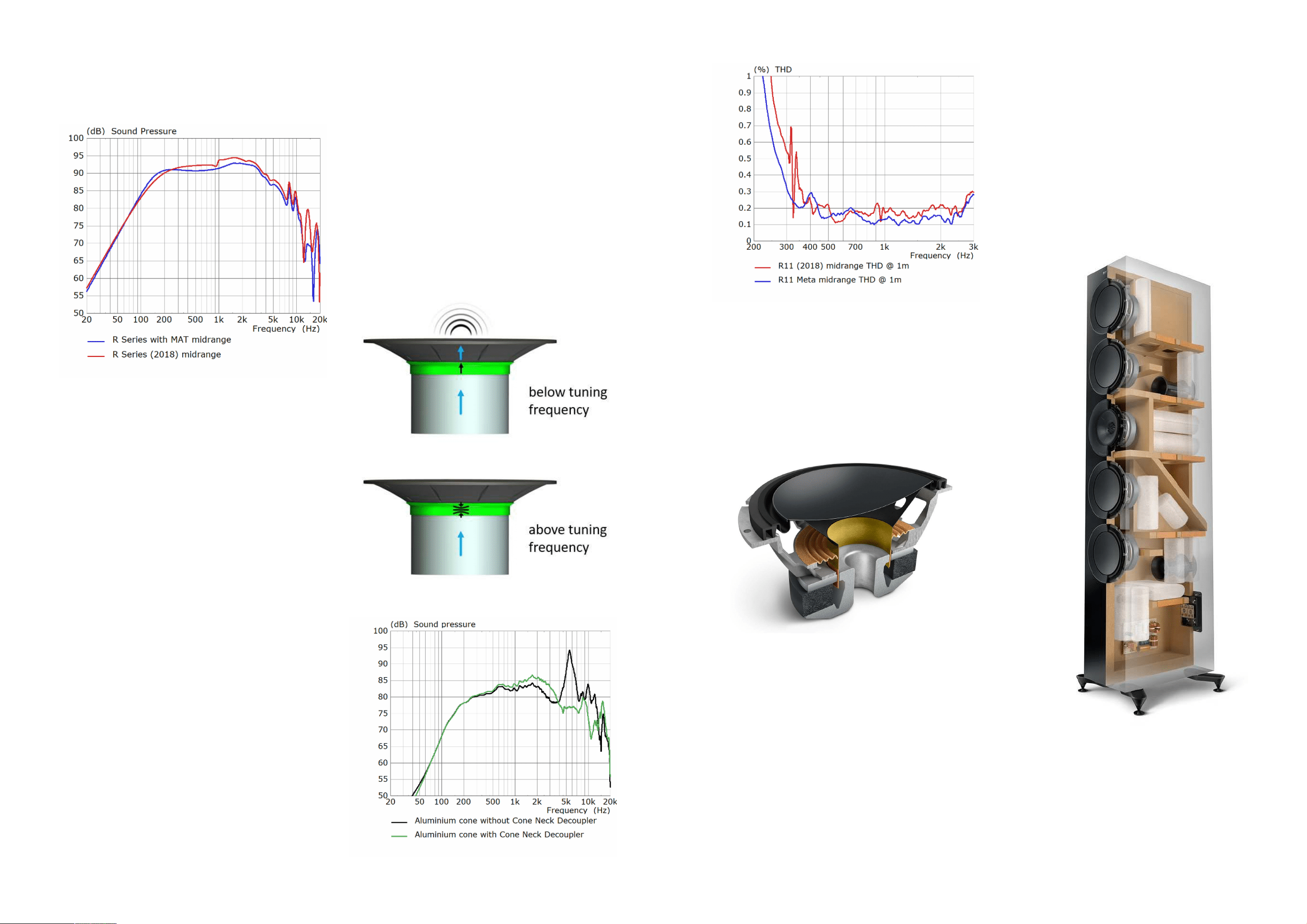
driver and the new midrange driver demonstra�ng the
disappearance of the dip at 950Hz caused by the
suspension resonance.
Midrange Cone Neck Decoupler
The midrange cone is made from an aluminium alloy to
ensure low mass and high rigidity. This results in pistonic
behaviour throughout the passband, which is an
essen�al requirement of a high-performance driver
design. However, due to low internal damping,
aluminium midrange cones typically break up in the
tweeter frequency region, resul�ng in severe peaks in
the frequency response and direc�vity aberra�ons that
remain audible despite the low-pass crossover on the
midrange.
To avoid these issues, a lossy interface between the
voice coil and the cone called the Cone Neck Decoupler
has been tuned to disconnect, or decouple, them just
below the break-up frequency (Figure 27). Figure 28
shows the eect of the Cone Neck Decoupler on the
midrange axial frequency response.
Midrange THD Performance
Figure 29 shows a comparison of THD (%) between the
2018 R Series midrange and the R Series with MAT
midrange, level-matched at 90dB at 1m, both measured
on an R11 enclosure without a crossover.
The following features can be highlighted:
• The distor�on is considerably lower at the lower
midrange frequencies as a result of the new split top
plate design.
• The overall drop in THD across the driver’s wide
passband owing to the new motor design
• The disappearance of the glitch around 310Hz where
the new decoupling chassis takes eect
• The disappearance of the glitch around 950Hz where
the suspension resonance has been dealt with by the
new midrange suspension design
Low Frequency Drivers
The low frequency drivers in R Series (Figure 30) provide
high output and low distor�on with high power handling
as well as pistonic mo�on well beyond their crossover
frequency.
They employ a lightweight and highly rigid moving
structure comprising an aluminium diaphragm coupled
to the voice coil through a paper cone with an angle and
coupling radius op�mised to push the rst break-up
frequency as high as 2.3kHz, by which point the driver
output is a�enuated more than 30dB with respect to the
system output.
A sizeable 50mm (2”) voice coil is employed for high
power handling. The motor employs a highly saturated
undercut pole design to reduce inductance and its
associated distor�on and a wide central vent to reduce
turbulence noise and acous�c loading from the air
trapped inside the voice coil.
The surround is a linear-excursion inverted half-roll
design that reduces the eect of dirac�on for the
neighbouring Uni-Q by not protruding from the speaker
bae.
System and Enclosure
Constrained Layer Damping
One of the main goals in high-performance loudspeaker
design is for all sound to emanate from the drivers, and
not from any other parts of the loudspeaker. Good
enclosure design is key to achieving this goal, as it must
Figure 28. Aluminium cone midrange axial frequency response with and without
Cone Neck Decoupler
Figure 27. Behaviour of the Cone Neck Decoupler (highlighted in green) around
tuning frequency
Figure 29. Comparison of measured THD (%) between R Series (2018) (red) and R
Series with MAT (blue) as measured on an R11 enclosure without crossover at 90 dB
SPL at 1m
Figure 31. R11 Meta system inside view
Figure 30. R Series LF driver
12 13
Figure 26. Midrange frequency response FEA simula�on on an innite bae
showing the disappearance of the ‘dip’ caused by the suspension resonance around
950Hz
remain as inert as possible without reac�ng to excita�on
from the drivers.
At low frequencies, the whole enclosure tends to move
in the opposite direc�on to the low frequency drivers’
diaphragms. To ameliorate this, the enclosure is built of
thick 25mm (1”) MDF and 30mm (1.18”) on the bo�om
face and front bae and anchored to the oor via four
protruding aluminium feet �ed with adjustable spikes.
The LF drivers are mounted on the front bae and are
constrained at the back with a transverse brace and a
proprietary damping material layer, eec�vely coupling
them with the mass of the enclosure.
At higher frequencies, even thick enclosure panels tend
to ex and resonate like the walls of a musical string
instrument. To reduce this eect, the inside of the
enclosure is heavily braced. However, bracing mostly
provides s�ness and some mass to the panels. This
reduces the velocity of the resona�ng panels to some
extent but mainly shi�s their resonance frequencies to
higher frequencies.
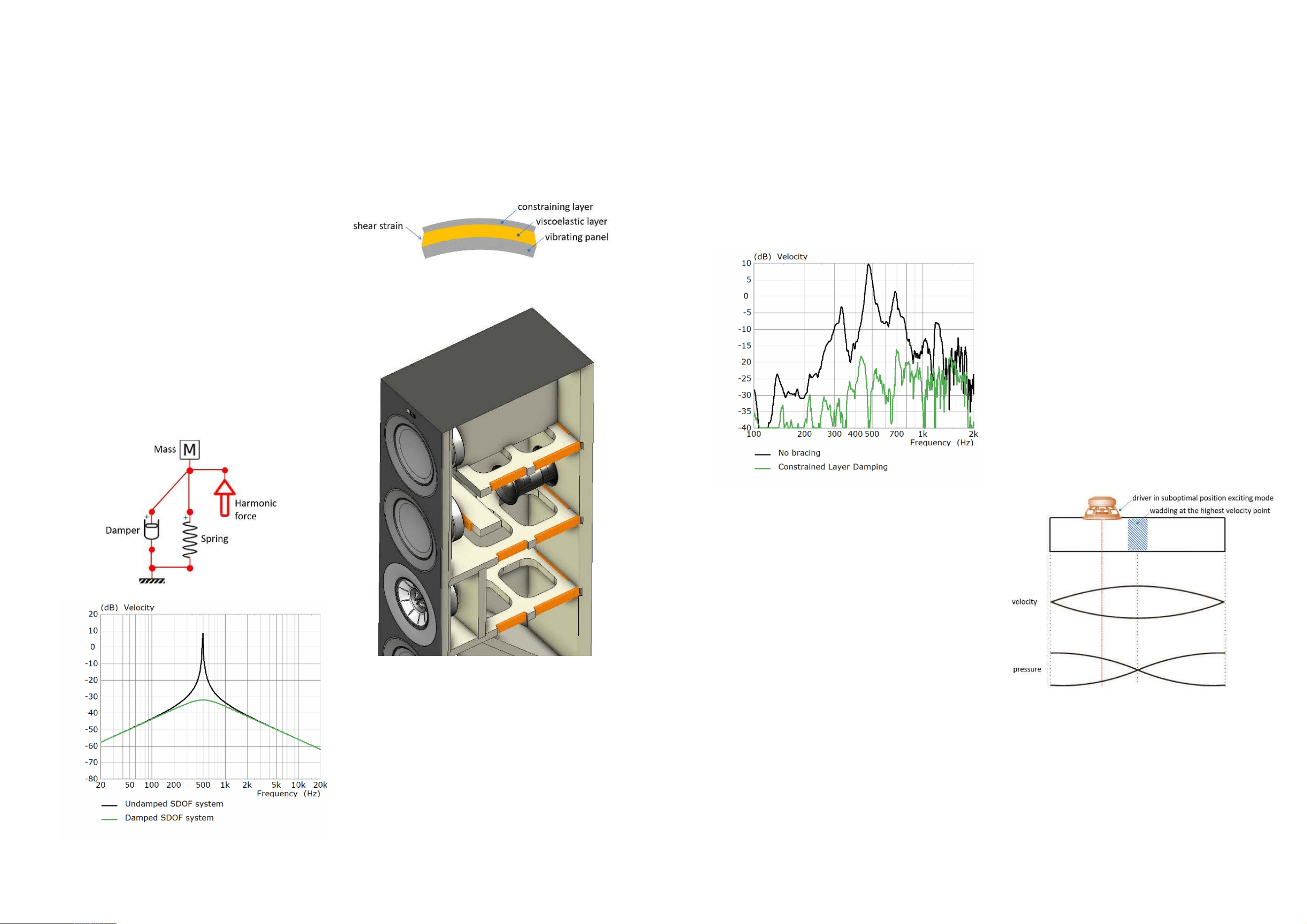
Adding resistance (damping) to a resona�ng system
reduces its velocity, just like a car suspension’s shock
absorber (damper) reduces the velocity of the
suspension’s resonance a�er a bump on the road. Figure
32 shows a diagram representa�on of a simple single-
degree-of-freedom (SDOF) resona�ng system and its
associated fundamental resonance velocity behaviour to
illustrate the eect of damping.
To dissipate energy away from the resonances and
reduce their amplitude, mechanical damping can be
provided by adding a layer of viscoelas�c material to the
vibra�ng panel. An arrangement that is well known in
acous�cs to deal with vibra�ng panels involves
employing a second layer of a s� material that
constrains the viscoelas�c one. This top layer causes
shearing of the viscoelas�c layer, increasing its damping
eect (Figure 33). Original research done during the
development of LS50 [8] showed a similar eect can be
achieved by using the cabinet braces as the constraining
top layer while a layer of viscoelas�c damping material is
used only in the interface area between the panels and
the braces (Figure 34). This layout outperforms lining the
en�re inside area of the panels while making a more
ecient use of the material.
Figure 35 shows a comparison of an enclosure wall
vibra�on measurement with and without bracing
incorpora�ng Constrained Layer Damping. The velocity
of the panel reects the appropriate broadband
a�enua�on of panel resonances.
Damping of standing wave
resonances
Another type of resonance that can occur within speaker
enclosures are acous�c standing waves. These acous�c
resonances take place when the air inside the enclosure
resonates when excited by the driver at frequencies
whose wavelength is rela�vely small compared to the
enclosure size. Due to the enclosure internal dimensions
and the posi�on of the drivers, one or several standing
waves may be excited, and they can easily colour the
sound from the speaker as they escape into the room
through the driver diaphragm, ports, or by exci�ng the
enclosure walls.
The most eec�ve way to mi�gate standing wave
resonances is to avoid exci�ng them in the rst place.
This is achieved through posi�oning the driver at the
resonances’ sound pressure nodes, i.e. where the sound
pressure is zero. In cases where drivers must be
posi�oned away from the pressure nodes due to their
exterior arrangement, other techniques must be used.
Acous�c damping materials, like wadding or foam,
provide a tortuous path for sound to travel through, i.e.
providing resistance (damping) to the air par�cles’
velocity.
When the air inside the enclosure is resona�ng, the
damping provided by the wadding is maximised when it
is posi�oned at the resonance’s highest velocity point.
This op�misa�on is relevant to avoid stung the
enclosure with wadding in inecient posi�ons which
reduce the enclosure’s internal volume, thus decreasing
low-frequency output with no other benet.
The Reference white paper from 2014 provides a
detailed descrip�on of the behaviour of standing waves
in enclosures and the eect of adding damping material
in dierent posi�ons within the enclosure [1].
Figure 36 depicts a simplied long enclosure closed at
both ends with a subop�mal asymmetric driver posi�on
along with the sound pressure and air par�cle velocity
proles of the rst longitudinal mode. The compromise
between driver posi�on and exci�ng and trea�ng the
standing wave can be visualised.
The arrangement and type of acous�c damping material
inside the midrange and low frequency cavi�es of R
Series with MAT has been re-op�mised to dampen
standing waves resul�ng in a perceivable sonic
enhancement in the clarity of the upper bass and
midrange.
Figure 37 shows measurements of the R11 Meta LF
driver diaphragm velocity taken with a laser vibrometer
Figure 36. First standing wave mode shape in a long enclosure with closed ends
Figure 35. Enclosure wall vibra�on comparison when adding the Constrained Layer
Damping arrangement
Figure 32. Single-degree-of-freedom system and its velocity with and without
damping
Figure 33. Diagram of a constrained layer damping arrangement
Figure 34. R11 Meta enclosure showing the bracing and viscoelas�c material
highlighted in orange forming the Constrained Layer Damping arrangement
14 15
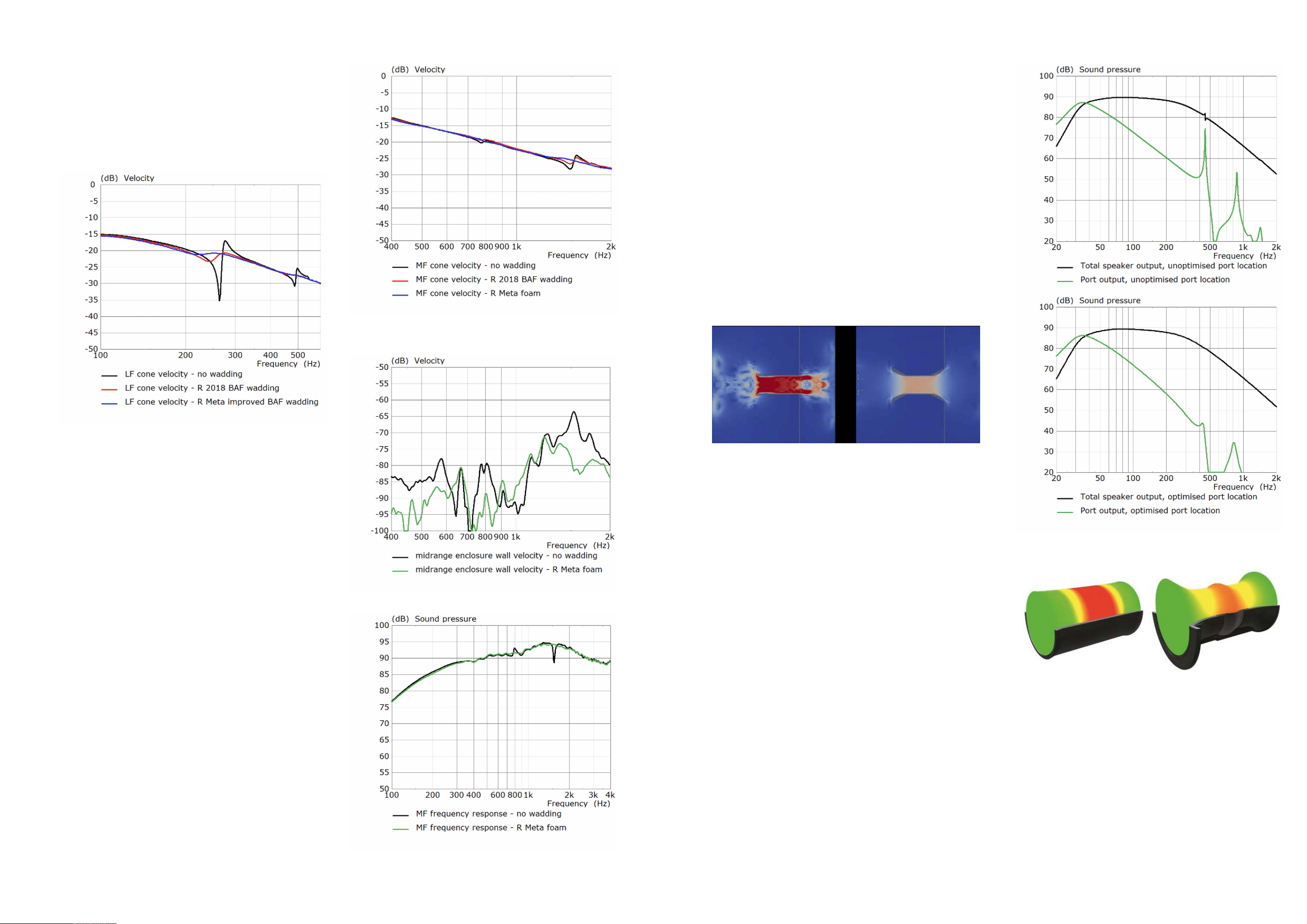
with and without wadding inside the enclosure. The
glitches observable in the response at ~250Hz and
490Hz correspond to the rst two longitudinal standing
waves and their disappearance is obvious when wadding
is added at strategic points. The further improvement
between R Series (2018) and R Series with MAT is
shown as well.
Figure 38 shows a similar comparison for the midrange
driver for resonances occurring at 770Hz and 1.5kHz.
For R Series with MAT the midrange acous�c damping
has been changed from BAF wadding to high-density
Ethylene-vinyl acetate (EVA) copolymer foam to further
increase damping of the sharp resonance around
1.5kHz.
Even with a s�, heavy, and well damped enclosure, the
high acous�c pressure of standing waves inside the
enclosure can press against the enclosure walls like a
balloon and make them vibrate, crea�ng a large radia�ng
surface for the resonance to eciently transduce into
radiated sound.
Figure 39 shows a comparison of the velocity of the
cabinet side wall of an R11 Meta outside the midrange
enclosure when foam is added while Figure 40 shows
the associated frequency response of the midrange
(without crossover) where the successful treatment of
the standing waves is observable and the loss in low-
frequency response is minimal.
Bass-reex ports
Bass-reex ports are very useful in passive
loudspeakers. At low frequency they are tuned to work
in tandem with the LF drivers and the enclosure’s
acous�c volume to further extend the system’s bass
response and reduce driver displacement and thus
distor�on.
However, ports add complica�ons to a system, two of
which are air turbulence noise and leakage of enclosure
standing waves at higher frequency.
The noise from air turbulence is greatly reduced by
op�mising the prole of the inner and outer port
opening ares through a Computer Fluid Dynamics
(CFD) numerical simula�on (Figure 41).
In R Series, the ports are located on the back of the
enclosure so that their internal opening can be freely
posi�oned in loca�ons that minimise the leakage of
internal acous�c resonances (Figure 42) (see Damping of
Standing Wave Resonances).
Another challenge seldom discussed with ports are their
inherent tube-like resonances. These resonances are
naturally related to the size of the port ac�ng like a small
organ pipe and at high frequencies, typically around
midrange, ports produce their own dis�nc�ve sound
that colours that of the drivers.
Since the introduc�on of LS50, and improved during the
development of the Reference Series, a mechanism has
been devised in which the wall of the tubular port
sec�on is made from a exible rubber that allows the
wall to expand with the acous�c pressure of the port
resonances. Since rubber has high internal damping, it
dissipates energy away from these resonances. This
results in a reduced acous�c output of the port
resonances, while the low-frequency behaviour of the
port remains unaected. Figure 43 shows the
mechanism of resonance damping through port exible
walls.
Crossover
The primary role of a crossover lter network is to
combine the output of the dierent drivers in a
speaker such that the transi�on between them is
smooth in magnitude and phase and that they work in
their intended frequency range away from damage and
distor�on.
Figure 37. Measured LF cone velocity of R11 Meta showing the eect of standing
waves and their improved damping
Figure 38. Measured midrange cone velocity of R11 Meta showing the eect of
standing waves and their improved damping
Figure 39. Measured surface velocity of cabinet wall outside midrange enclosure in
R11 Meta comparing the standing wave leakage with and without acous�c damping
Figure 40. Measured frequency response of the midrange in R11 Meta (no crossover)
comparing the standing wave leakage with and without acous�c damping (at 1m
distance)
Figure 43. Pressure of the rst resonance in a port with rigid walls (top) and exible
walls (bo�om)
Figure 42. System output simula�on showing the eect of op�mised port loca�on
on standing wave leakage
Figure 41. CFD model showing the eect of the computer-op�mised port are
geometry on air turbulence
16 17
However, to maximise the communica�on of spa�al
cues in a recording that enhances the realis�c
percep�on of the stereo image by the listener, a
speaker’s frequency response must be designed to be
smooth on-axis as well as o-axis, both ver�cally and
horizontally. This is so that the room’s early reected
sound has a tonal balance that is not abruptly dissimilar
to the speaker’s direct sound.
Therefore, a secondary but equally important func�on
of the crossover is to help ensure this smooth transi�on
occurs in all direc�ons, not only on the speaker’s frontal
axis.
To design such a crossover, it is necessary to simulate it
rst through a virtual computer model of the crossover
network and feed it with measurements of the
impedance and anechoic frequency response of the LF,
MF and HF sec�ons playing individually.
Figure 44 shows a 3D representa�on of the
measurement data acquisi�on system used in KEF’s
anechoic chamber. An array of omnidirec�onal
microphones captures the anechoic frequency response
of the speaker at various ver�cal angles. The speaker is
then rotated on a turntable and the measurement is
repeated every few degrees. This results in a sphere of
frequency response data that can be fed into the
computer model and post-processed to produce
relevant acous�c metrics. These metrics then inform the
crossover design in terms of how the speaker’s
individual driver outputs are combined.
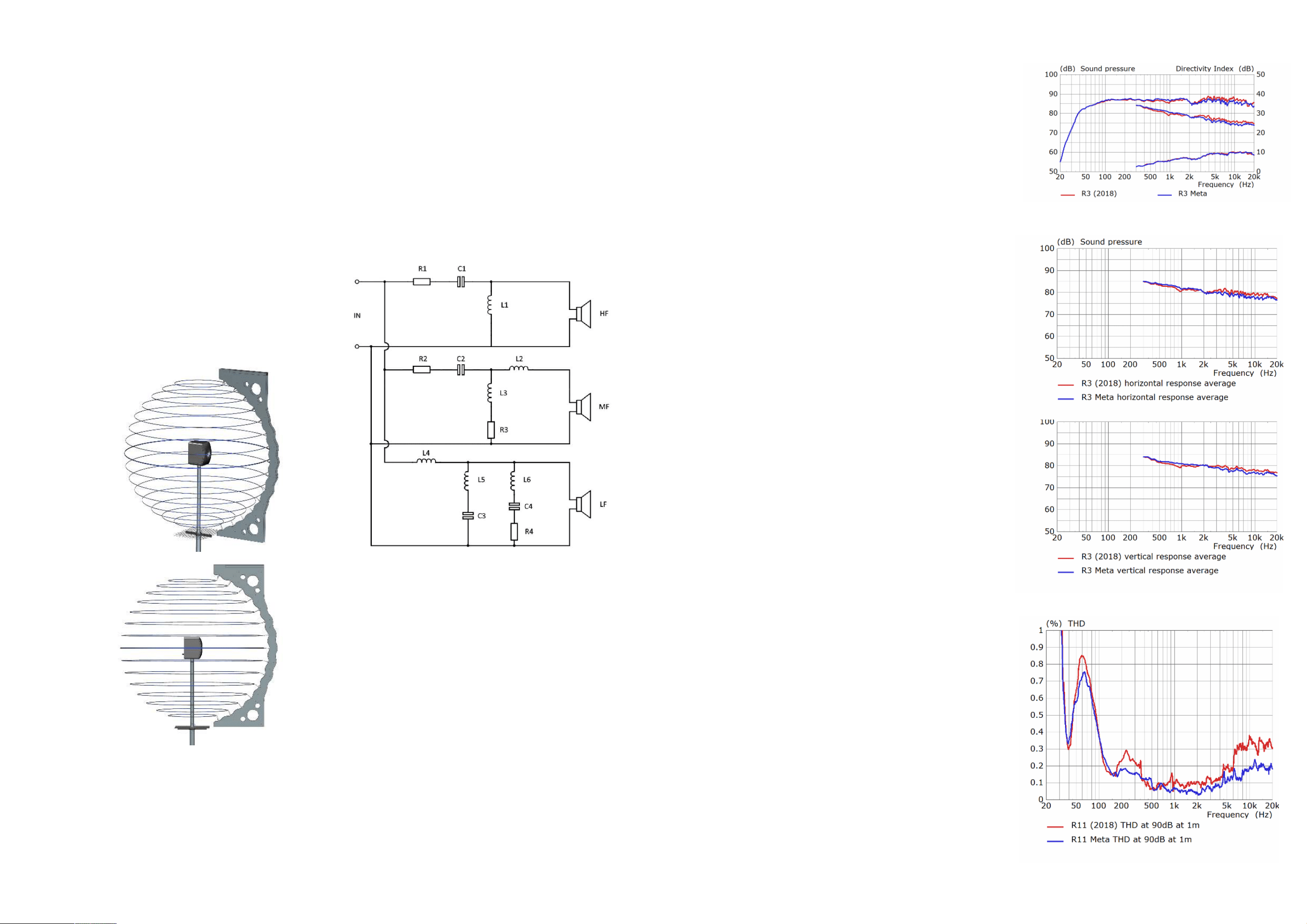
Figure 45 shows the crossover topology used across the
series consis�ng of a three-way network, except for R8
Meta which uses a dierent 2-way topology op�mised
for Dolby Atmos®.
The new topology simplies the tweeter lter to
improve the system’s direc�vity, uses a single series
capacitor C2 in the MF branch, and only uses C3 in the
LF branch in some models to help tailor their direc�vity
across LF to MF.
The tweeter series capacitor (C1) has been upgraded to
a be�er design Polypropylene lm one with a thicker
lm, lower resistance contact layer (schoopage), lower
resistance terminals and a thicker outer damping layer.
Where possible, air core inductors have been used and
all cored inductors have a laminated steel core of a
specially selected grade to reduce THD.
In R Series with MAT the overall frequency response and
direc�vity smoothness have been further improved. To
improve direc�vity, priority has been assigned to
obtaining a smoother acous�c power average and
smoother ver�cal and horizontal direc�vity averages.
These curves are special averages of the speaker’s o-
axis response. As an example, Figures 46 and 47 show a
comparison of the balance between R3 (2018) and R3
Meta, where a smoother result has been achieved.
The R3 Meta is a special case within the range as the LF
sec�on does not form a symmetrical arrangement
around the Uni-Q, since it has only one LF driver. For this
reason, the Uni-Q is mounted close to the top edge of
the enclosure, and this results in a dip in its acous�c
power direc�vity index just above 2kHz. Designing a
crossover considering only the axial response
smoothness would result in a corresponding bump in the
acous�c power average. The studied approach,
however, allows a dip in the axial response, priori�sing a
smooth power average. This represents the approach
rened during the development of Reference Meta [8]
as well as extensive listening tests in dierent rooms.
System THD Performance
The aggregate outcome of the improvements outlined in
the previous sec�ons can be somewhat summarised in
the system’s total harmonic distor�on. Figure 48 shows
a comparison of THD (%) at 90dB SPL matched at 500Hz
at 1m distance between R11 (2018) and R11 Meta. The
full audible frequency band is shown to highlight the
results from the mul�ple improvements in the system.
The measurements show the reduced harmonic
distor�on across the high frequency band covered by
the tweeter, the very low distor�on across the midrange
passband (~0.1%), the disappearance of the glitch at
950Hz associated with the MF suspension resonance,
the suppression of the bump around 250Hz due to the
lower distor�on midrange motor and a broad
improvement to the LF sec�on mainly due to the
crossover design.
Summary
The R Series was originally introduced as a more
aordable op�on to the Reference Series while directly
bene�ng from the research conducted during the
development of KEF’s highest performance ranges.
The R Series with MAT carries on this legacy by
integra�ng numerous acous�c innova�ons, resul�ng in
objec�vely be�er performance in the laboratory and a
Figure 47. Horizontal (top) and ver�cal (bo�om) response average of R3 (2018) (red)
vs. R3 Meta (blue)
Figure 46. Axial frequency response, acous�c power average and acous�c power
average direc�vity index of R3 (2018) (red) vs. R3 Meta (blue)
Figure 48. Comparison of THD (%) between R11 (2018) (red) and R11 Meta (blue) at
90dB SPL matched at 500Hz at 1m
Figure 44. Representa�on of the measurement data acquisi�on system in KEF’s
anechoic chamber
Figure 45. Main crossover topology for R Series with MAT (3-way models)
18 19

more realis�c and engaging musical reproduc�on experience
in the listening room.
This paper aims to provide insight into the development
process of these innova�ons by explaining their engineering
and suppor�ng its arguments with results from computer
simula�ons and laboratory measurements.
The tweeter metamaterial absorber, innova�ve drivers,
enclosure acous�cal behaviour, and new crossover lter
networks together combine to result in a loudspeaker range
with a much higher capability for faithful and engaging
musical reproduc�on.
References
[1] “The Reference (White Paper).” KEF R&D,
Apr. 2014. [Online]
[2] “R Series 2018 (White Paper).” KEF R&D, Oct.
2018. [Online]
[3]
M. Dodd and J. Oclee-Brown, “A New Methodology
for the Acous�c Design of Compression Driver
Phase Plugs with Radial Channels”, 125
th
Audio
Eng. Soc. Conven�on, 2008
[4] S. Degraeve and J. Oclee-Brown, “Metamaterial
Absorber for Loudspeaker Enclosures”, 148
th
Audio
Eng. Soc. Conven�on 2020
[5] “LS50 Collec�on (White Paper).” KEF R&D, Sep.
2020 [Online]
[6] M. Dodd, “Optimum Diaphragm and Waveguide
Geometry for Coincident source Drive Units”,
121
st
Audio Eng. Soc. Conven�on 2006
[7] “Blade/The Reference with MAT (White Paper).”
KEF R&D, Feb. 2022. [Online]
[8] “LS50 (White Paper).” KEF R&D, Sep. 2011.
[Online]
20 21
R Series Meta
Model Informa�on, Specica�ons and
Measurements
22
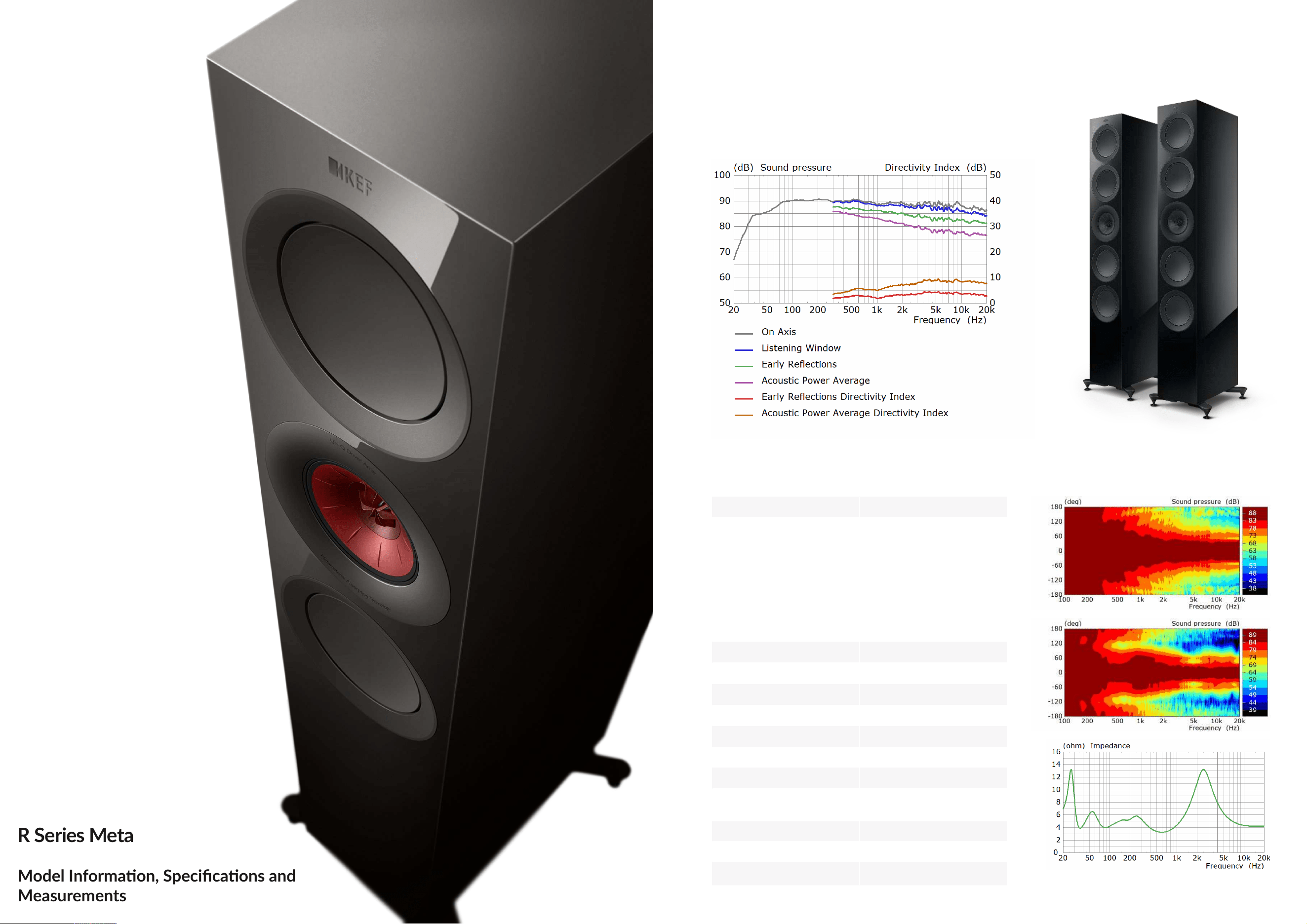
R11 Meta
Three-way Floorstanding Loudspeaker
Technical Specica�ons
System
Three-way bass reex
Drive units
Uni-Q Driver Array:
HF: 25 mm (1 in.) aluminium
dome with MAT
MF: 125 mm (5 in.)
aluminium cone
Bass Drivers:
LF: 4 x 165mm (6.5 in.)
hybrid aluminium cone
Frequency range free-eld
(-6dB)
30Hz - 50kHz
Typical in-room bass
response (-6dB)
26Hz
Frequency response
(±3dB)
46Hz - 28kHz
Crossover frequencies 330Hz, 2.5kHz
Recommended amplier
power
15-300W
Sensi�vity (2.83V/1m) 90dB
Harmonic distor�on
2
nd
& 3
rd
harmonics (90dB, 1m)
<1% 33Hz and above
<0.5% 80Hz - 20kHz
Maximum output
(Peak sound pressure level at
1m with pink noise)
113dB
Impedance
4 Ω (min. 3.2 Ω
Weight 36.5kg (80.5 lbs)
Dimensions with plinth
(H x W x D)
1296 x 311 x 384 mm
(51.0 x 12.2 x 15.1 in.)
R11 Meta Spinorama
R11 Meta direc�vity contours - horizontal (top) and ver�cal (middle) - and
impedance (bo�om)
23
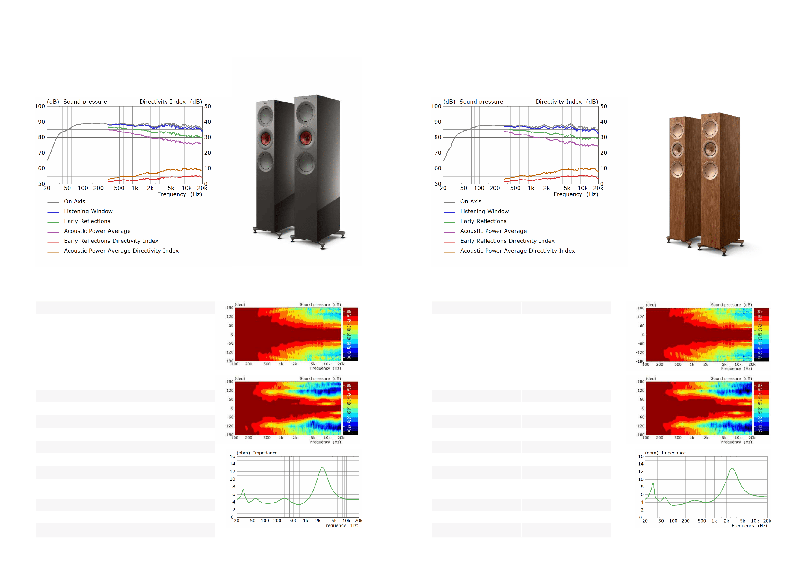
R7 Meta
Three-way Floorstanding Loudspeaker
Technical Specica�ons
R5 Meta
Three-way Floorstanding Loudspeaker
System
Three-way bass reex
Drive units
Uni-Q Driver Array:
HF: 25 mm (1 in.) aluminium
dome with MAT
MF: 125 mm (5 in.)
aluminium cone
Bass Drivers:
LF: 2 x 165mm (6.5 in.)
hybrid aluminium cone
Frequency range free-eld
(-6dB)
33Hz - 50kHz
Typical in-room bass
response (-6dB)
27Hz
Frequency response
(±3dB)
48Hz - 28kHz
Crossover frequencies 400Hz, 2.4kHz
Recommended amplier
power
15-250W
Sensi�vity (2.83V/1m) 88dB
Harmonic distor�on
2
nd
& 3
rd
harmonics (90dB, 1m)
<1% 76Hz and above
<0.5% 110Hz - 20kHz
Maximum output
(Peak sound pressure level at
1m with pink noise)
111dB
Impedance
4 Ω (min. 3.2 Ω)
Weight 29.3kg (64.6 lbs)
Dimensions with plinth
(H x W x D)
1109 x 311 x 384 mm
(43.7 x 12.2 x 15.1 in.)
Technical Specica�ons
System
Three-way bass reex
Drive units
Uni-Q Driver Array:
HF: 25 mm (1 in.) aluminium
dome with MAT
MF: 125 mm (5 in.)
aluminium cone
Bass Drivers:
LF: 2 x 130mm (5.25 in.)
hybrid aluminium cone
Frequency range free-eld
(-6dB)
38Hz - 50kHz
Typical in-room bass
response (-6dB)
29Hz
Frequency response
(±3dB)
52Hz - 28kHz
Crossover frequencies 400Hz, 2.7kHz
Recommended amplier
power
15-200W
Sensi�vity (2.83V/1m) 87dB
Harmonic distor�on
2
nd
& 3
rd
harmonics (90dB, 1m)
<1% 75Hz and above
<0.5% 110Hz - 20kHz
Maximum output
(Peak sound pressure level at
1m with pink noise)
110dB
Impedance
4 Ω (min. 3.2 Ω)
Weight 24.5kg (54.0 lbs)
Dimensions with plinth
(H x W x D)
1025 x 272 x 344 mm
(42.2 x 10.7 x 13.5 in.)
24
R5 Meta Spinorama
R5 Meta direc�vity contours - horizontal (top) and ver�cal (middle) - and
impedance (bo�om)
R7 Meta Spinorama
R7 Meta direc�vity contours - horizontal (top) and ver�cal (middle) - and
impedance (bo�om)
25
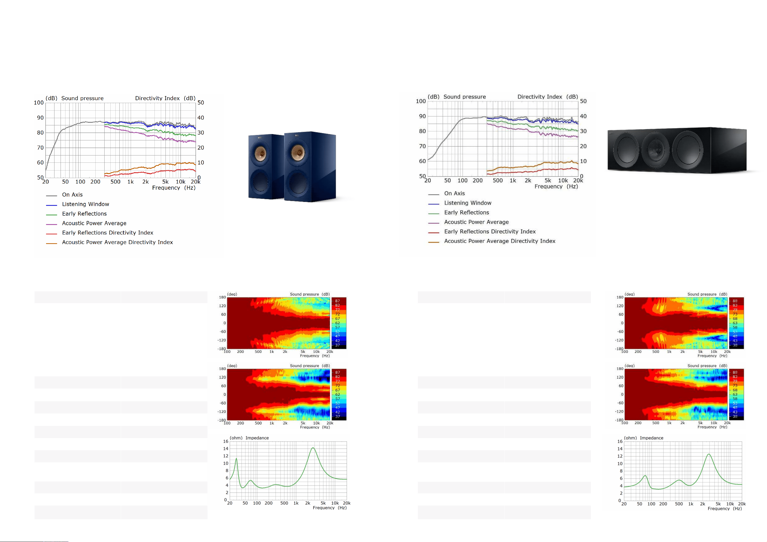
R3 Meta
Three-way Bookshelf Loudspeaker
R6 Meta
Three-way Centre Loudspeaker
Technical Specica�ons
System Three-way bass reex
Drive units
Uni-Q Driver Array:
HF: 25 mm (1 in.) aluminium
dome with MAT
MF: 125 mm (5 in.)
aluminium cone
Bass Driver:
LF: 165mm (6.5 in.)
hybrid aluminium cone
Frequency range free-eld
(-6dB)
38Hz - 50kHz
Typical in-room bass
response (-6dB)
30Hz
Frequency response
(±3dB)
58Hz - 28kHz
Crossover frequencies 420Hz, 2.3kHz
Recommended amplier
power
15-180W
Sensi�vity (2.83V/1m) 87dB
Harmonic distor�on
2
nd
& 3
rd
harmonics (90dB, 1m)
<1% 73Hz and above
<0.5% 90Hz - 20kHz
Maximum output
(Peak sound pressure level at
1m with pink noise)
110dB
Impedance
4 Ω (min. 3.2 Ω)
Weight 12.4kg (27.3 lbs)
Dimensions with plinth
(H x W x D)
422 x 200 x 336 mm
(16.6 x 7.9 x 13.2 in.)
Technical Specica�ons
System
Three-way bass reex
Drive units
Uni-Q Driver Array:
HF: 25 mm (1 in.) aluminium
dome with MAT
MF: 125 mm (5 in.)
aluminium cone
Bass Drivers:
LF: 2 x 165mm (6.5 in.)
hybrid aluminium cone
Frequency range free-eld
(-6dB)
55Hz - 50kHz
Typical in-room bass
response (-6dB)
40Hz
Frequency response
(±3dB)
65Hz - 28kHz
Crossover frequencies
550Hz, 2.4kHz
Recommended amplier
power
15-250W
Sensi�vity (2.83V/1m) 88dB
Harmonic distor�on
2
nd
& 3
rd
harmonics (90dB, 1m)
<1% 65Hz and above
<0.5% 93Hz - 20kHz
Maximum output
(Peak sound pressure level at
1m with pink noise)
111dB
Impedance
4 Ω (min. 3.2 Ω)
Weight 17.8kg (39.2 lbs)
Dimensions with plinth
(H x W x D)
200 x 625 x 339 mm
(7.9 x 24.6 x 13.3 in.)
R6 Meta Spinorama
R6 Meta direc�vity contours - horizontal (top) and ver�cal (middle) - and
impedance (bo�om)
R3 Meta Spinorama
R3 Meta direc�vity contours - horizontal (top) and ver�cal (middle) - and
impedance (bo�om)
26 27
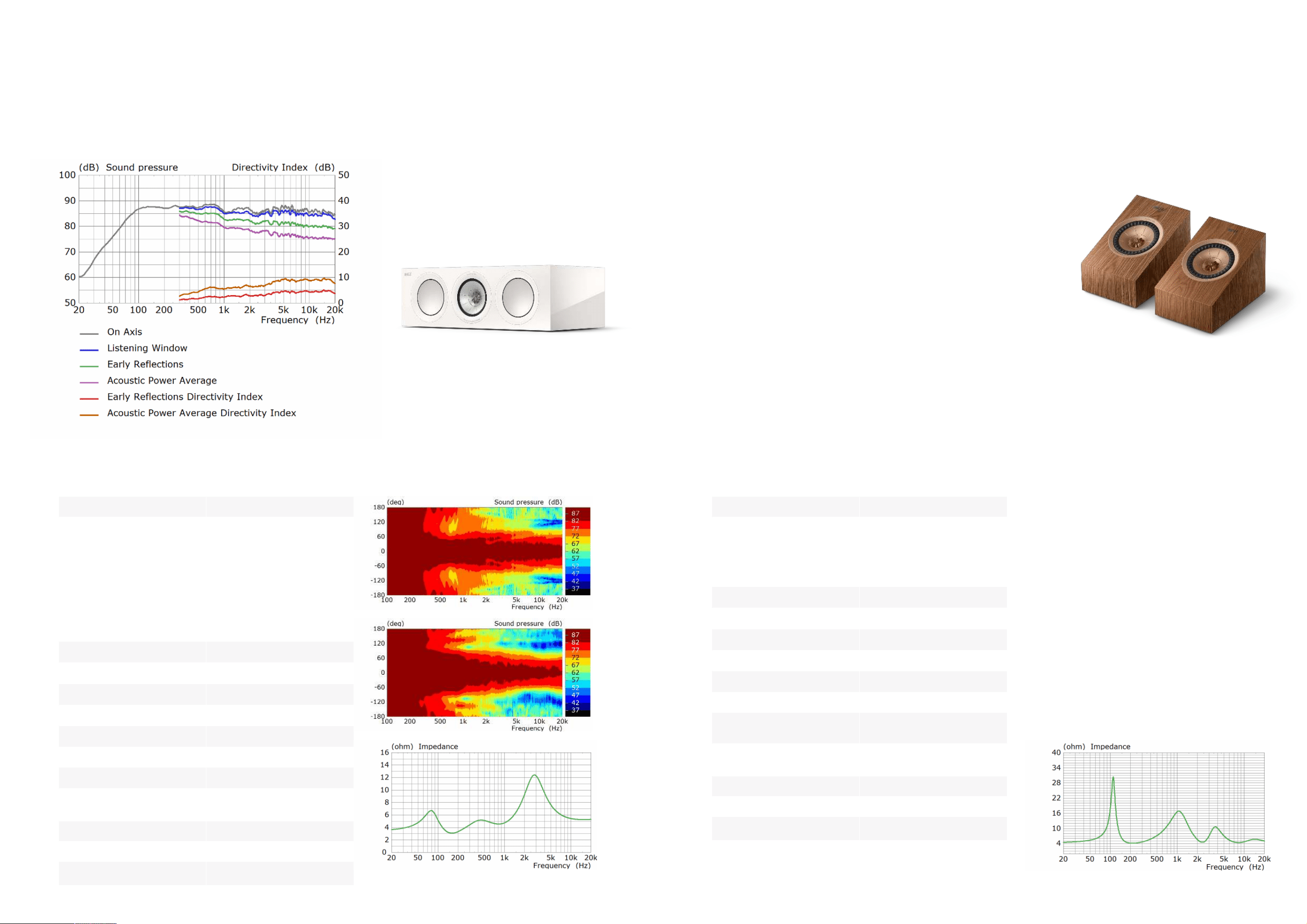
R2 Meta
Three-way Centre Loudspeaker
R8 Meta
Two-way surround/Dolby Atmos
Loudspeaker
Technical Specica�ons
System
Three-way bass reex
Drive units
Uni-Q Driver Array:
HF: 25 mm (1 in.) aluminium
dome with MAT
MF: 125 mm (5 in.)
aluminium cone
Bass Drivers:
LF: 2 x 130mm (5.,25 in.)
hybrid aluminium cone
Frequency range free-eld
(-6dB)
58Hz - 50kHz
Typical in-room bass
response (-6dB)
43Hz
Frequency response
(±3dB)
67Hz - 28kHz
Crossover frequencies 560Hz, 2.5kHz
Recommended amplier
power
15-200W
Sensi�vity (2.83V/1m) 87dB
Harmonic distor�on
2
nd
& 3
rd
harmonics (90dB, 1m)
<1% 84Hz and above
<0.5% 95Hz - 20kHz
Maximum output
(Peak sound pressure level at
1m with pink noise)
110dB
Impedance
4 Ω (min. 3.2 Ω)
Weight 15.4kg (34.0 lbs)
Dimensions with plinth
(H x W x D)
175 x 550 x 309 mm
(6.9 x 21.7 x 12.2 in.)
Technical Specica�ons
System
Two-way closed box
Drive units
Uni-Q Driver Array:
HF: 25 mm (1 in.) aluminium
dome with MAT
MF/LF: 130 mm (5.25 in.)
aluminium cone
Frequency range free-eld
(-6dB)
88Hz - 19.5kHz
Typical in-room bass
response (-6dB)
-
Frequency response
(
±3dB)
97Hz - 17.5kHz
Crossover frequencies 2.6kHz
Recommended amplier
power
25-150W
Sensi�vity (2.83V/1m) 85dB
Harmonic distor�on
2
nd
& 3
rd
harmonics (90dB,
1m)
<1% 220Hz and above
<0.5% 320Hz - 20kHz
Maximum output
(Peak sound pressure level at
1m with pink noise)
106dB
Impedance 4 Ω (min. 3.2 Ω)
Weight 4.5kg (9.9 lbs)
Dimensions with plinth
(H x W x D)
174 x 175 x 259 mm
(6.9 x 6.9 x 10,2 in.)
R2 Meta Spinorama
R2 Meta direc�vity contours - horizontal (top) and ver�cal (middle) - and
impedance (bo�om)
28 29
R8 Meta impedance