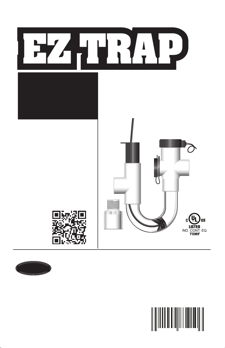
(EZT113)
U.S. Patent Numbers 5,069,042 5,522,229
Kit Contents
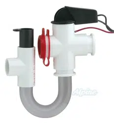
3/4″ Standard Trap (1)
3/4″ Cross (1)
3/4″ Tee (1)
Red Cap (1)
Brush Holder (1)
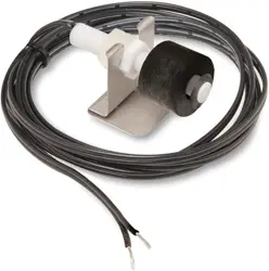
Float Switch Assembly (1)
72″ Modular Cable (1)
3/4″ Adaptor (1)
Cleaning Brush (1)
Red/Blue Service Label (1)
Yellow Cleaning Label (1)
3/4ʺ Condensate
Trap with Overow
Switch
1” DROP
RectorSeal® 2601 Spenwick Drive - Houston, TX 77055
ph: 713.263.8001 - 800.231.3345 fax: 713.263.7577 - 800.441.0051
www.rectorseal.com - Like Us on Facebook
Scan for more info
961755
0 2 1 4 4 9 8 3 2 1 0 6
®
Model No.
83210
(EZT210)
New!
Compact Modular
Switch Assembly
▼
LIMITED WARRANTY. RectorSeal
®
warrants to the original consumer purchaser (“Purchaser”)
of its product, EZ Trap
®
, that it is free from defects in material or workmanship. If within two years (24 months)
from the date of the original consumer purchase this product shall prove to be defective, it shall be repaired or replaced at
RectorSeal’s option. Your original receipt of purchase is required to determine warranty eligibility.
2 Year
Trap Assembly Instructions
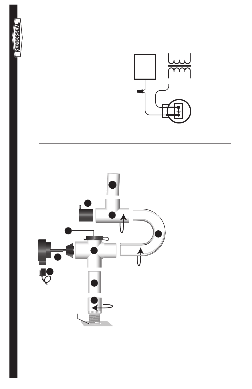
1. Screw Adaptor (A) into 3/4” primary drain pan outlet.
2. Dry t, and mark components. Rotate U-Bend (D)
and Outlet Tee (E) to required angles for installation.
3. Glue components (B thru E) using dry t markings.
Glue assembly into Adaptor (A)
4. Glue Drain Line (F) into center leg of Outlet Tee (E). Drain Line must exit building with at least a 5°angle.
5. Press t Float Switch (G) into opening at top of Inlet Cross (C). DO NOT USE GLUE.
Check that Actuator Arm moves freely inside Inlet Cross.
6. Check that Red Cap (H) is tightly secured.
7. Press plug end of Modular Cable (J) into Float Switch Assembly (G)
8. Place brush into retaining hole on Brush Holder (K).
9. Attach service & cleaning labels as indicated.
Note: Insulation is required when trap is installed in unconditioned space where sweating can occur.
Installation Instructions
Model No.
83210
(EZT210)
E
B
A
Drain Pan Outlet
Not included
Not included
5° angle
C
G
J
F
H
K
D
Wiring Instructions
1. Turn off power at main panel before opening unit and
working on electrical system.
2. An inline fuse is necessary to protect the 24V circuit .
3. Connect Float Switch using wiring diagram. (below)
4. Test system for proper operation by lifting oat.
Note: Wiring diagram shown cuts power to thermostat when oat switch
operates to stop operation of the A/C unit. To inhibit mold growth during long
absences, connect terminals into yellow cooling circuit so when oat
switch operates, condenser will switch off but fan will continue running.
X1
red
rojo
black
negro
black
negro
EZ-TRAP SWITCH
TRANSFORMER
TRANSFORMADOR
24V
X2
THERMOSTAT
TERMOSTATO
Important:
Install in strict accordance
with RectorSeal
®
instructions
as well as all applicable
local plumbing, drainage and
electrical codes.