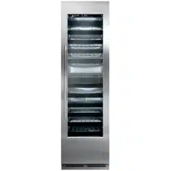
SERVICE MANUAL
Column Refrigeration
Residential and Commercial
Product Series Covered in this Manual:
Commercial
CC24D
CC24W
Residential
CR24D
CR24F
CR24R
CR24W
CR30R
Scan here to
download a PDF copy
of this manual.
Form No. Z2551
Rev. C: 05/03/2019
CC24W
CR24FCR24R

2
Column Refrigeration Service Manual
1.0 GENERAL INFORMATION ........................................................................................ 10
1.1 Use of Service Manual ..............................................................................................10
1.2 Model Families .........................................................................................................10
1.3 I.D. Plate ................................................................................................................10
2.0 SAFETY INFORMATION ........................................................................................... 11
2.1 Refrigerant HC-600a ................................................................................................. 11
2.2 Servicing with R-600a ............................................................................................... 11
2.2.1 General .....................................................................................................11
2.2.2 Transportation of refrigerant and replaced compressors ................................11
2.2.3 Tools ......................................................................................................... 11
2.3 Service Manual Safety Labels ....................................................................................11
2.4 Product Safety Labels ...............................................................................................12
3.0 TROUBLESHOOTING GUIDE ....................................................................................13
3.1 Refrigeration System ................................................................................................13
3.2 Electrical System ......................................................................................................17
3.3 Doors, Drawers, Shelving ..........................................................................................19
4.0 ELECTRICAL COMPONENTS AND SPECIFICATIONS ................................................20
4.1 Compressor .............................................................................................................20
4.1.1 MODEL: VEMX5C .......................................................................................20
4.1.2 MODEL: VEMZ9C .......................................................................................20
4.2 Inverter ................................................................................................................20
4.2.1 Drop-In .....................................................................................................20
4.2.2 MODEL: Frequency Drive ............................................................................ 20
4.3 Condenser Fan Motor ...............................................................................................20
4.4 Evaporator Fan Motor ...............................................................................................20
4.5 Hot Gas Defrost Solenoid Valve .................................................................................21
4.6 Control ................................................................................................................21
4.7 Damper ................................................................................................................21
4.8 User Interface ..........................................................................................................21
5.0 COMPONENT OPERATION .......................................................................................22
5.1 Modes Of Operation .................................................................................................22
Model: CR24R and CR30R ......................................................................................... 22
Model: CR24F ..........................................................................................................23
Models: CR24W or CC24W ........................................................................................ 24
Models: CR24D or CC24D .........................................................................................25
5.2 ElectricalSpecications ............................................................................................. 26
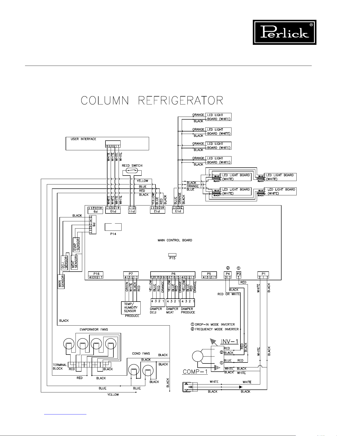
5.3 Wiring Diagrams ......................................................................................................27
Column Refrigerator .................................................................................................27
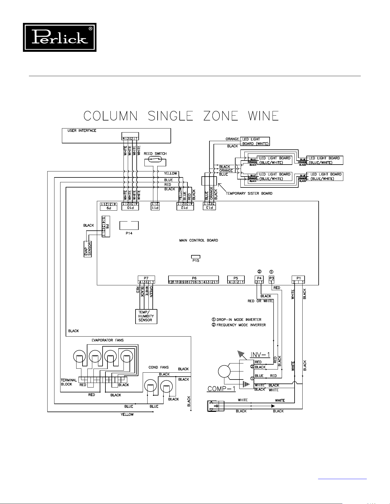
Column Single-Zone Wine .........................................................................................28
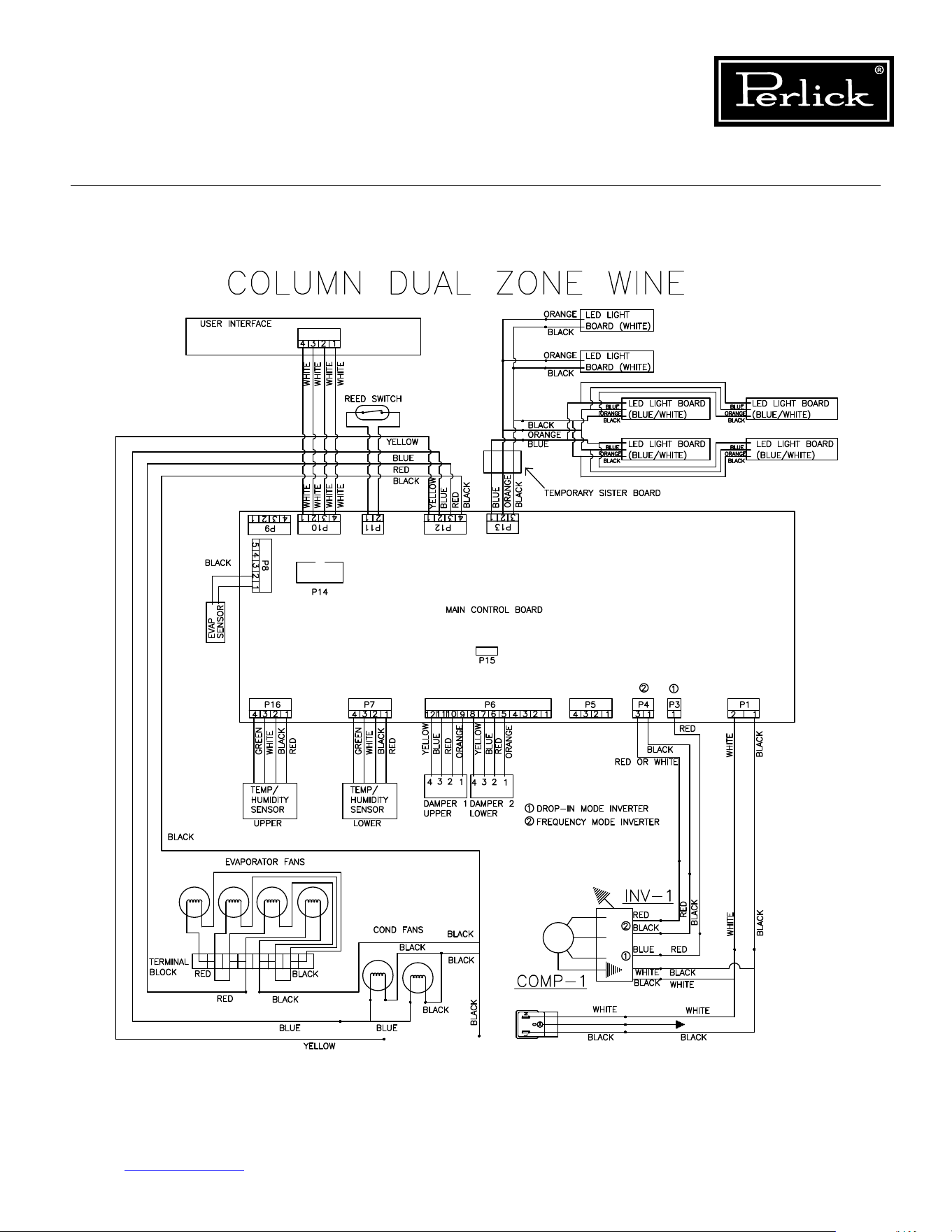
Column Dual Zone Wine ...........................................................................................29
Table of Contents
Table of Contents

Table of Contents
3
Column Refrigeration Service Manual
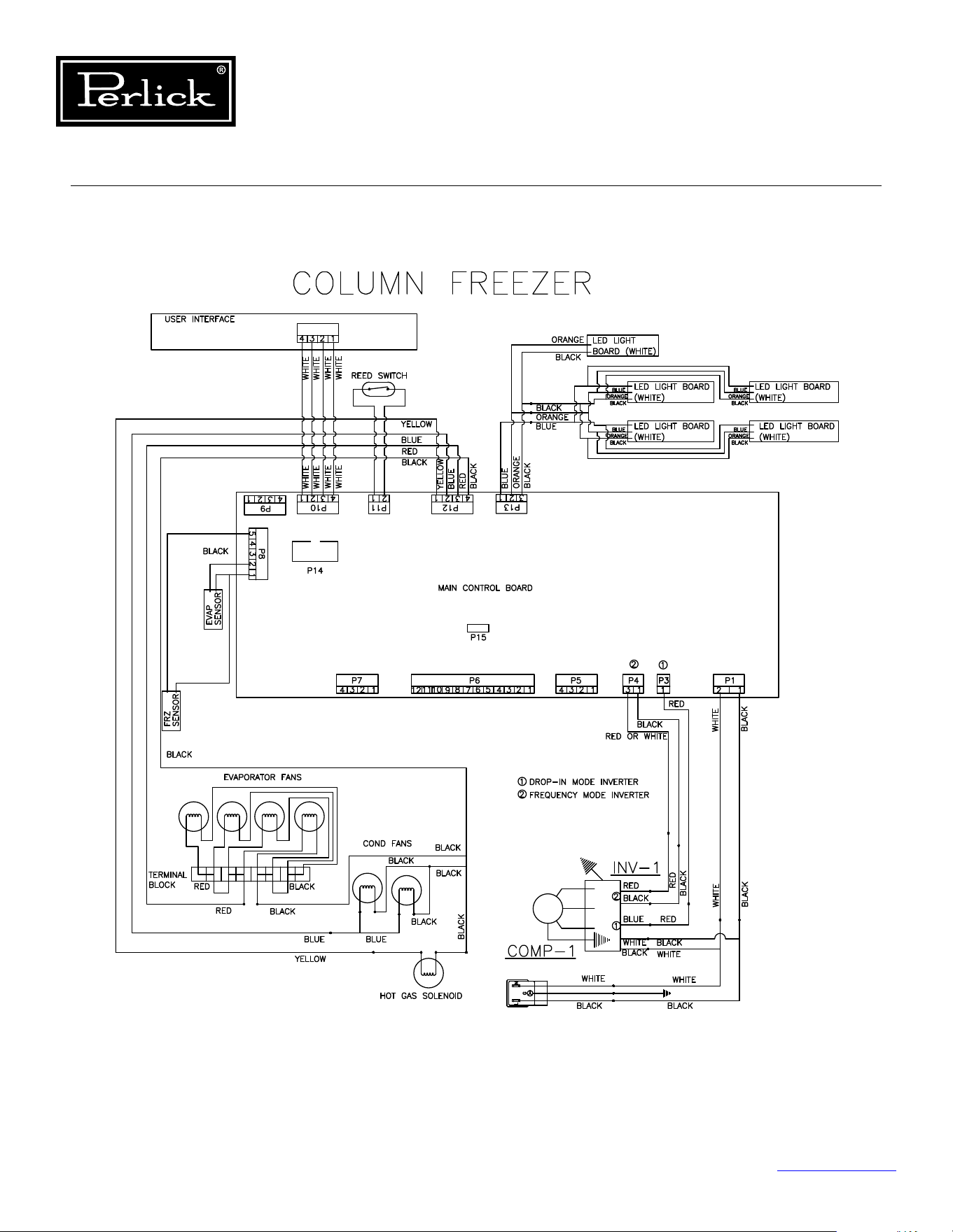
Column Freezer ........................................................................................................30
5.4 Control Alarms .........................................................................................................31
5.5 Refrigerator Control Operation ..................................................................................32
5.5.1 Using The Refrigerator Column Control ........................................................ 32
5.5.2 Selecting A Temperature Zone ....................................................................32
5.5.3 Main Compartment ....................................................................................33
5.5.4 Top Drawer Compartment ...........................................................................33
5.5.5 Middle Drawer Compartment ......................................................................33
5.5.6 Bottom Drawer Compartment .....................................................................34
5.5.7 Column Theater Lighting ............................................................................35
5.5.8 Changing From Fahrenheit To Celsius Scale ..................................................35
5.5.9 Sabbath Mode ...........................................................................................35
5.5.10 Quick Cool (Shopping) Mode ....................................................................... 36
5.5.11 Showroom Mode ........................................................................................ 36
5.6 Freezer Control Operation .........................................................................................37
5.6.1 Using The Freezer Column Control ..............................................................37
5.6.2 Freezer Temperature ..................................................................................37
5.6.3 Column Theater Lighting ............................................................................38
5.6.4 Changing From Fahrenheit To Celsius Scale ..................................................38
5.6.5 Sabbath Mode ...........................................................................................38
5.6.6 Quick Cool (Shopping) Mode ....................................................................... 38
5.6.7 Showroom Mode ........................................................................................ 39
5.7 Wine Reserve Control Operation ................................................................................40
5.7.1 Using The Wine Column Control .................................................................. 40
5.7.2 Selecting A Temperature Zone ....................................................................40
5.7.3 Storing White Wine ....................................................................................41
5.7.4 Storing Red Wine .......................................................................................41
5.7.5 Cellaring Wine ...........................................................................................42
5.7.6 Column Theater Lighting ............................................................................42
5.7.7 Changing From Fahrenheit To Celsius Scale ..................................................43
5.7.8 Quick Cool (Shopping) Mode ....................................................................... 43
5.7.9 Showroom Mode ........................................................................................ 43
5.7.10 Ambient Conditions ....................................................................................43
6.0 REFRIGERATION SYSTEM REPAIR ..........................................................................44
6.1 AirInltration ..........................................................................................................44
6.2 Ambient Temperatures .............................................................................................46
6.2.1 Freezer Ambient Conditions ........................................................................46
6.3 Air Flow Obstructions ...............................................................................................46
6.4 Condenser Coil Cleaning ...........................................................................................48
6.5 De-Ice Blocked Evaporator Coil .................................................................................49
Table of Contents (cont.)

4
Column Refrigeration Service Manual
6.6 Replace Refrigeration Module .................................................................................... 50
6.7 Replace Condenser Fan Motor ...................................................................................53
6.8 Replace Evaporator Fan Motor ...................................................................................53
6.9 Replace Inverter ......................................................................................................54
6.10 Replace Damper .......................................................................................................59
6.11 Leak Detection ......................................................................................................... 60
6.12 Refrigeration System Diagram - Medium Temperature ................................................. 61
6.13 Refrigeration System Diagram - Freezer .....................................................................62
7.0 COMPONENT OPERATION .......................................................................................63
7.1 Control ................................................................................................................63
7.1.1 Diagnostics ................................................................................................63
7.1.2 Troubleshooting .........................................................................................63
7.1.3 Visible LED Descriptions .............................................................................64
7.1.4 Replacing ..................................................................................................65
7.2 User Interface (Replacing) ........................................................................................65
7.3 Lighting Replacement ...............................................................................................66
7.3.1 Replace Wine Lighting ................................................................................66
7.4 Temperature Probes .................................................................................................71
7.4.1 Probe Locations .........................................................................................72
7.4.2 Troubleshooting .........................................................................................73
7.5 Door Switch ............................................................................................................. 73
7.5.1 Troubleshooting .........................................................................................73
8.0 DOORS, DRAWERS, SHELVING AND MISC. .............................................................74
8.1 Overlay Panel Installation And Adjustments ................................................................74
8.2 Top Of Door Illustration ............................................................................................75
8.3 Door Trim Installation ............................................................................................... 76
8.4 Grill Installation ........................................................................................................77
8.5 Toe Kick Clearance ...................................................................................................78
8.6 Installing Filters .......................................................................................................79
8.6.1 Carbon Air Filters .......................................................................................79
8.6.2 Ethylene Filters ..........................................................................................79
8.7 Activation/De-activation Of Hinges .............................................................................80
8.8 Replace Door Gasket ................................................................................................81
8.9 Replace Door ...........................................................................................................81
8.10 Replace Door Handle ................................................................................................82
8.11 Lock Installation And Troubleshooting ........................................................................83
8.12 Custom Overlay Door Panels .....................................................................................84
8.12.1 24” Solid Door Template For 4” Toe Kick ......................................................85
8.12.2 30” Solid Door Template For 4” Toe Kick ......................................................86
8.12.3 24” Solid Door Template For 6” Toe Kick ......................................................87
8.12.4 30” Glass Door Template For 6” Toe Kick .....................................................88
Table of Contents (cont.)
Table of Contents

Table of Contents
5
Column Refrigeration Service Manual
8.12.5 24” Glass Door Template For 4” Toe Kick .....................................................89
8.12.6 24” Glass Door Template For 6” Toe Kick .....................................................90
8.12.7 24” Screw Zone For Overlay Templates ........................................................ 91
8.12.8 30” Screw Zone For Overlay Templates ........................................................ 92
8.13 Tip-Out Bin .............................................................................................................. 93
8.14 Drawers .............................................................................................................. 100
8.14.1 Deli And Meat Drawer .............................................................................. 100
8.14.2 Freezer Drawers ...................................................................................... 101
8.15 Drawer Compartment Dividers ................................................................................ 102
8.16 Shelving .............................................................................................................. 103
8.16.1 Wine Shelving .......................................................................................... 103
8.16.2 Freezer Shelving ...................................................................................... 104
8.16.3 Refrigerator Shelving ................................................................................ 105
8.17 Dual-Zone Wine Compartment Divider ..................................................................... 106
8.18 Leveling/Alignment ................................................................................................. 107
8.19 Cabinet Anti-Tip/Anti-Tip Bracket ............................................................................. 108
8.19.1 Anti-Tip Installation For Integrated Installation ........................................... 109
8.19.2 Anti-Tip Installation For Freestanding Installation ....................................... 110
8.20 Marriage Kit Installation .......................................................................................... 111
8.21 Butter Bin .............................................................................................................. 115
8.22 Trim Kits .............................................................................................................. 116
9.0 REPLACEMENT PARTS ...........................................................................................117
9.1 CR24R, CR24D, CR24W, CC24D, CC24W, And CR30R Refrigeration Module ................. 117
9.2 CR24F Refrigeration Module .................................................................................... 118
9.3 CR24F Drawers ...................................................................................................... 119
9.4 CR24R Shelving ..................................................................................................... 120
9.5 CR30R Shelving ..................................................................................................... 121
9.6 CR24R, CR24F, And CR30R Door ............................................................................. 122
9.7 CR24R And CR30R Drawers .................................................................................... 123
9.8 CR24R And CR30R Damper Tip-Out Bin ................................................................... 124
9.9 CR24R, CR24D, CR24W, CC24D, CC24W, And CR30R Machine Compartment .............. 125
9.10 CR24D, CR24W, CC24D And CC24W Shelving ........................................................... 126
9.11 CR24D, CR24W, CC24D And CC24W Door ................................................................ 127
9.12 CR24F Column Freezer ........................................................................................... 128
9.13 CR24R And CR30R Column Refrigerator ................................................................... 129
9.14 CR24D And CC24D Dual-Zone Wine Column ............................................................. 130
9.15 CR24W And CC24W Single-Zone Wine Column ......................................................... 131
9.16 CR24W And CC24W Single-Zone Wine Column Shelves ............................................. 132
Table of Contents (cont.)

6
Column Refrigeration Service Manual
Figure 1-1. Information Plate for Refrigeration Units ......................................................................10
Figure 2-1.1. Danger Fire/Explosion Risk Label ..............................................................................12
Figure 2-1.2. Danger Fire/Explosion Risk Servicing Label ................................................................12
Figure 2-1.3. Warning Handling Label ...........................................................................................12
Figure 2-1.4. Warning Tip-Over Hazard Label ................................................................................12
Figure 2-1.5. Disposal Label .........................................................................................................12
Figure 2-1.6. Warning Transporting Hazard Label ...........................................................................12
Figure 2-1.7. Uncrating Label .......................................................................................................12
Figure 5-1.1. Column Refrigerator Wiring Diagram .........................................................................27
Figure 5-1.2. Wine Column Single Zone Wiring Diagram .................................................................28
Figure 5-1.3. Wine Column Dual-Zone Wiring Diagram ...................................................................29
Figure 5-1.4. Column Freezer Wiring Diagram ...............................................................................30
Figure 5-2. Refrigerator Touch Screen Control ...............................................................................32
Figure 5-3. Freezer Touch Screen Control ......................................................................................37
Figure 5-4. Wine Reserve Touch Screen Control .............................................................................40
Figure 6-1.1. Sealing Compound (Inside) ......................................................................................44
Figure 6-1.2. Sealing Compound (Outside) ....................................................................................44
Figure 6-1.3. Sealing Compound - Door Switch (Inside) .................................................................44
Figure 6-1.4. Sealing Compound - Door Switch (Outside) ...............................................................44
Figure 6-2.1. Refrigerator Gasket ..................................................................................................45
Figure 6-2.2. Lift Bolts .................................................................................................................45
Figure 6-3. Evaporator Condensate Drain ......................................................................................45
Figure 6-4.1. Grill/Toe Kick Inlet and Outlet ...................................................................................46
Figure 6-4.2. Evaporator Intake Openings .....................................................................................46
Figure 6-5.1. Evaporator Air Outlet Louvers ...................................................................................47
Figure 6-5.2. Evaporator Air Damper Outlet Openings ....................................................................47
Figure6-6.CondenserAirowDivider ...........................................................................................47
Figure 6-7.1. Remove Grill ............................................................................................................48
Figure 6-7.2. Clean Condenser Coil ...............................................................................................48
Figure 6-8. Freezer Drawer ..........................................................................................................49
Figure 6-9.1. Wine Shelves ..........................................................................................................49
Figure 6-9.2. Bottom Shelves/Bottom Panel ................................................................................... 49
Figure 6-10. Tip-Out Bin/Inner Liner .............................................................................................49
Figure 6-11. Evaporator Coil .........................................................................................................49
Figure 6-12.1. Remove Grill ..........................................................................................................50
Figure 6-12.2. Remove Lift Bracket ...............................................................................................50
Figure 6-12.3. Disconnect Refrigeration Wiring ..............................................................................50
Figure 6-12.4. Lower Refrigeration Module ....................................................................................51
Figure 6-12.5. Slide Refrigeration Module Out ................................................................................51
Figure 6-12.6. Disconnect Power Cord ..........................................................................................51
Figure 6-12.7. Slide Unit Back Into Cabinet .................................................................................... 52
Figure 6-12.8. Reinstall Front Lift Bracket ......................................................................................52
Figure 6-13. Condenser Fan Motor/Fastener ..................................................................................53
Table of Figures
Table of Contents

Table of Contents
7
Column Refrigeration Service Manual
Figure 6-14.1. Evaporator Fan Motor/Fastener ...............................................................................53
Figure 6-14.2. Evaporator Terminal Block ......................................................................................53
Figure 6-15.1. Remove Cotter Pins................................................................................................54
Figure 6-15.2. Lift And Rotate Compressor ....................................................................................54
Figure 6-15.3. Inverter Mounting Screw/Electrical Connections .......................................................55
Figure 6-15.4. Lift Inverter ...........................................................................................................55
Figure 6-15.5. Remove 3-Pin And Ground Connectors ....................................................................56
Figure 6-15.6. Install Inverter And Remount Compressor ...............................................................56
Figure 6-15.7. Connect Inverter Wires ...........................................................................................57
Figure 6-15.8. Feed Harness End Through Access Hole ..................................................................57
Figure 6-15.9. Seal Access Hole ....................................................................................................58
Figure 6-15.10. Connect New Harness ..........................................................................................58
Figure 6-16.1. Refrigerator And Dual-Zone Wine Lower Damper .....................................................59
Figure 6-16.2. Dual-Zone Wine Upper Damper ..............................................................................59
Figure 6-16.3. Dual-Zone Wine Upper Damper (Cover And Insulation Pad Suppressed) ....................59
Figure 6-16.4. Damper Electrical Connection .................................................................................59
Figure 6-17.1. Refrigeration System Diagram (Medium Temperature) ..............................................61
Figure 6-17.2. Refrigeration System Diagram (Freezer) ..................................................................62
Figure 7-1. Visible LED Descriptions ..............................................................................................64
Figure 7-2.1. Remove Wine Shelving .............................................................................................66
Figure 7-2.2. Pry Light Covering ...................................................................................................67
Figure 7-2.3. Pry Light Housing Board ...........................................................................................67
Figure 7-2.4. Disconnect Board From Harness ...............................................................................68
Figure 7-2.5. Remove Wine Shelving .............................................................................................68
Figure 7-2.6. Remove Carbon Filter ..............................................................................................69
Figure 7-2.7. Remove Wire Harness Cover .....................................................................................69
Figure 7-2.8. Remove Controller Cover ..........................................................................................70
Figure 7-2.9. Disconnect Light Harness .........................................................................................70
Figure 7-3.1. Evaporator Temperature Probe .................................................................................72
Figure 7-3.2. Dual-Zone Wine Lower Compartment Temperature/Humidity Sensor ...........................72
Figure 7-3.3. Dual-Zone Upper And Single-Zone Temperature/Humidity Sensor ................................72
Figure 7-3.4. Freezer And Refrigerator (Main Compartment) Temperature Probe ..............................72
Figure 7-3.5. Refrigerator Deli Bin Temperature Probe ....................................................................72
Figure 7-3.6. Refrigerator Meat/Fish Bin Temperature Probe ...........................................................72
Figure 7-3.7. Refrigerator Tip-Out Bin Temp/Humidity Sensor .........................................................72
Figure 7-4. Door Magnet (Reed Switch) ........................................................................................73
Figure 8-1. Overlay Panel Installation ............................................................................................ 74
Figure 8-2. Top Of Door Illustration ..............................................................................................75
Figure 8-3. Door Trim Installation .................................................................................................76
Figure 8-4. Grill Installation ..........................................................................................................77
Figure 8-5. Toe Kick Clearance .....................................................................................................78
Figure 8-6. Air Filter Installation ...................................................................................................79
Figure 8-7.1. Hinge Activation Fastener (De-Activated) ...................................................................80
Table of Figures (cont.)

8
Column Refrigeration Service Manual
Figure 8-7.2. Hinge Activation Fastener (T-20) (Activated) ..............................................................80
Figure 8-8. Removing Gasket .......................................................................................................81
Figure 8-9. Removing Door Trim Cover .........................................................................................82
Figure 8-10. Lock Installation .......................................................................................................83
Figure 8-11.1. CR24 Solid Door Template for 4” Toe Kick ................................................................85
Figure 8-11.2. CR30R Solid Door Template for 4” Toe Kick .............................................................. 86
Figure 8-11.3. CR24 Solid Door Template for 6” Toe Kick ................................................................87
Figure 8-11.4. CR30 Solid Door Template for 6” Toe Kick ................................................................88
Figure 8-11.5. CR24 Glass Door Template for 4” Toe Kick ...............................................................89
Figure 8-11.6. CR24 Glass Door Template for 6” Toe Kick ..............................................................90
Figure 8-12.1. CR24 Screw Zone For Overlay Templates .................................................................91
Figure 8-12.2. CR30 Screw Zone For Overlay Templates .................................................................92
Figure 8-13.1. - 8-13.4. Refrigerator Tip-Out Bin Removal ..............................................................93
Figure 8-14 - Deli And Meat Drawer Release ................................................................................100
Figure 8-15.1 - Freezer Drawer Slide ...........................................................................................101
Figure 8-15.2 - Freezer Drawer Release ......................................................................................101
Figure 8-16 - Drawer Compartment Divider And Retaining Pin ......................................................102
Figure 8-17.1. & 8-17.2. Remove Wine Shelves ............................................................................ 103
Figure 8-17.3. & 8-17.4. Install Wine Shelves...............................................................................103
Figure 8-18. Freezer Shelving ..................................................................................................... 104
Figure 8-19. Refrigerator Shelving ..............................................................................................105
Figure 8-20.1. & 8-20.2. Dual-Zone Compartment Divider ............................................................106
Figure 8-21. Leveling/Alignment .................................................................................................107
Figure 8-22.1. Anti-tip Installation (Integrated) ...........................................................................109
Figure 8-22.2. Anti-tip Installation (Freestanding) ........................................................................110
Figure 8-23.1. - 8-23.4. Marriage Kit Install .................................................................................111
Figure 8-24.1. Butter Bin............................................................................................................115
Figure 8-25. Trim Kit ..................................................................................................................116
Figure 9-1. CR24R, CR24D, CR24W, CC24D, CC24W, and CR30R Refrigeration Module ....................117
Figure 9-2. CR24F Refrigeration Module ......................................................................................118
Figure 9-3. CR24F Drawers ........................................................................................................119
Figure 9-4. CR24R Shelving ........................................................................................................ 120
Figure 9-5. CR30R Shelving ........................................................................................................121
Figure 9-6. CR24R, CR24F, and CR30R Door ................................................................................ 122
Figure 9-7. CR24R and CR30R Drawers .......................................................................................123
Figure 9-8. Damper Tip-Out Bin .................................................................................................124
Figure 9-9. CR24R, CR24D, CR24W, CR24F, CC24D, CC24W, and CR30R Machine Compartment ......125
Figure 9-10. CR24D, CR24W, CC24D and CC24W Shelving ............................................................126
Figure 9-11. CR24D, CR24W, CC24D and CC24W Door ................................................................. 127
Figure 9-12. CR24F - Column Freezer .........................................................................................128
Figure 9-13. CR24R - Column Refrigerator ...................................................................................129
Figure 9-14. CR24D & CC24D - Dual-Zone Wine Column ..............................................................130
Figure 9-15. CR24W & CC24W - Single-Zone Wine Column ...........................................................131
Figure 9-16. CR24W & CC24W - Single-Zone Wine Column Shelves ...............................................132
Table of Figures (cont.)
Table of Contents

Table of Contents
9
Column Refrigeration Service Manual
Table 3.1. Refrigeration System Diagnostics/Troubleshooting .....................................................13
Table 3.2. Electrical System Diagnostics/Troubleshooting ...........................................................17
Table 3.3. Doors, Drawers, Shelving Diagnostics/Troubleshooting ..............................................19
Table 4.1.1. Compressor Specs (Model VEMX5C) ......................................................................20
Table 4.1.2. Compressor Specs (Model VEMV9C) ......................................................................20
Table 4.2.1. Inverter Specs (Drop-In) .......................................................................................20
Table 4.2.2. Inverter Specs (Frequency Drive) ..........................................................................20
Table 4.3. Condenser Fan Motor Specs ..................................................................................... 20
Table 4.4. Evaporator Fan Motor Specs ....................................................................................20
Table 4.5. Hot Gas Defrost Solenoid Valve Specs .......................................................................21
Table 4.6. Control Specs .........................................................................................................21
Table 4.7. Damper Specs .........................................................................................................21
Table 5.1.1. Modes of Operation (CR24R and CR30R) ...............................................................22
Table 5.1.2. Modes of Operation (CR24F) .................................................................................23
Table 5.1.3. Modes of Operation (CR24W/CC24W) ....................................................................24
Table 5.1.4. Modes of Operation (CR24D/CC24D) .....................................................................25
Table5.2.ElectricalSpecications ............................................................................................26
Table 5.3. Control Alarms ........................................................................................................ 31
Table5.4.Low/HighTemperatureAlarmOsets .......................................................................31
Table 5.5. Ambient Conditions (Wine Reserve) ..........................................................................43
Table 6.1. Ambient Conditions (Freezer) ...................................................................................46
Table 7.1. LED Diagnostics ......................................................................................................63
Table 7.2. LED Troubleshooting ................................................................................................63
Table 7.3. Column Temperature/Humidity Sensors.....................................................................71
Table 7.4. Temperature - Resistance Values ..............................................................................71
Table 8.1. Lock Troubleshooting ..............................................................................................83
Table of Tables
Column Refrigeration Service Manual
Return to Table of Contents
10
1.0 General Information
1.1 Use of Service Manual
This service manual is intended for use by a
qualiedservicetechnician.Itisprovidedasa
guide to diagnose and repair service issues for the
product models listed on the cover.
If you have any questions or require additional
assistance, contact Perlick Customer Service during
regular hours of operation.
1.2 Model Families
Thismanualcontainsspecicinstructionsfor
servicing the Perlick Residential and Front Venting
Commercial Series refrigeration products, which
include the following families:
RESIDENTIAL COMMERCIAL
CR24D CC24D
CR24F CC24W
CR24R
CR24W
CR30R
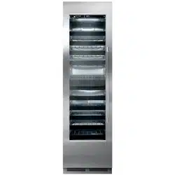
1.3 I.D. Label
The model and serial numbers can be found on the
ceiling of the refrigerated space. See Figure 1-1.
Figure 1-1. Information Plate for
Refrigeration Units
Column Refrigeration Service Manual
Return to Table of Contents
11
2.3 Service Manual Safety Labels
PLEASE READ all instructions completely before
attempting to service the unit. Take particular
note of the DANGER, WARNING and CAUTION
information in this manual. The information
isimportantforthesafeandecientservice,
operation and care of the Perlick unit.
HAZARD!! Indicates hazardous situation that
will result in death or serious injury if not
avoided.
Indicates hazardous situation that may
result in death or serious injury if not
avoided.
Caution indicates hazardous situation that
could result in minor or moderate injury and
property damage.
Caution without symbol indicates unsafe practice
situation that could result in property damage only.
• Vacuum pumps must be explosion-safe. It must
be possible to lead the discharge air from the
vacuum pump into open air.
• Leak detection cannot take place with normal
halogen leak detectors, as they do not react on
hydrocarbons. A special detector reacting on
a hydrocarbon must be used instead. Another
possibility is to use a leak spray. Both solutions
only work properly if the vapor pressure in
the system is higher than 1 bar (atmospheric
pressure).
• If the pressure is lower than the normal
atmospheric pressure, it is necessary to raise
the pressure within the system to ambient
temperature.
Never use liquid to detect system leaks if
system is in a vacuum!
All self-contained models covered in this service
manual are manufactured using refrigerant
HC-600a (Isobutane).
2.2 Servicing with R-600a
R600a is a hydrocarbon. This refrigerant is
ammableandisonlyallowedforuseinappliances
whichfullltherequirementsofUL60335-2-24
(To cover potential risk originated from the use of
ammablerefrigerants).Consequently,R600ais
only allowed to be used in household appliances
whicharedesignedforthisrefrigerantandfulll
the above-mentioned standard.
• R600a is heavier than air. The concentration
willalwaysbehighestatoorlevel.
• The explosion limits are as follows:
Lower limit: 1.5% by vol. (38 g/m3)
Upper limit: 8.5% by vol. (203 g/m3)
Ignition temperature: 460°C
2.2.1 General
Do not use near open re. To carry out service
and repair on R600a systems the service personnel
must be properly trained to be able to handle a
ammablerefrigerant.Thisincludesknowledge
on tools, transportation of compressors and
refrigerant, and the relevant regulations and safety
precautions when carrying out service and repair.
2.2.2 Transportation of refrigerant and
replaced compressors
• The refrigerant must be stored and transported
in approved containers.
• Replaced compressors containing refrigerant
residues must be sealed before being
transported.
2.2.3 Tools
Ingeneral:Noopenrewhentroubleshootingand
repairing.
• The refrigeration circuit must be opened with a
tube cutter or a special tool.
2.0 Safety Information
2.1 Refrigerant HC-600a
WARNING
CAUTION
WARNING
WARNING
DANGER
CAUTION
Column Refrigeration Service Manual
Return to Table of Contents
12
2.0 Safety Information
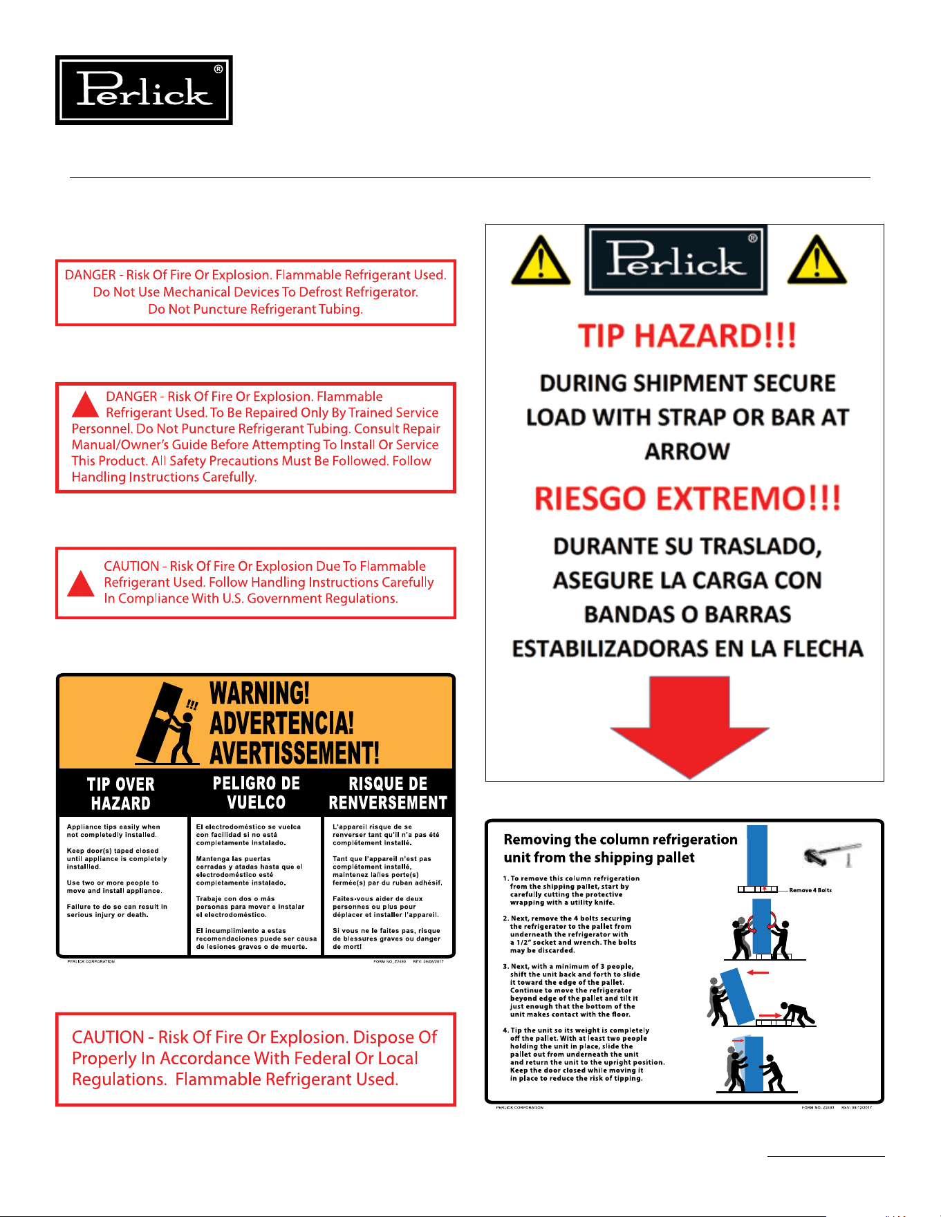
2.4 Product Safety Labels
Figure 2-1.6. Warning Transporting Hazard Label
Figure 2-1.7. Uncrating Label
Figure 2-1.1. Danger Fire/Explosion Risk Label
Figure 2-1.2. Danger Fire/Explosion Risk Servicing
Label
Figure 2-1.3. Warning Handling Label
Figure 2-1.4. Warning Tip-Over Hazard Label
Figure 2-1.5. Disposal Label
Column Refrigeration Service Manual
Return to Table of Contents
13
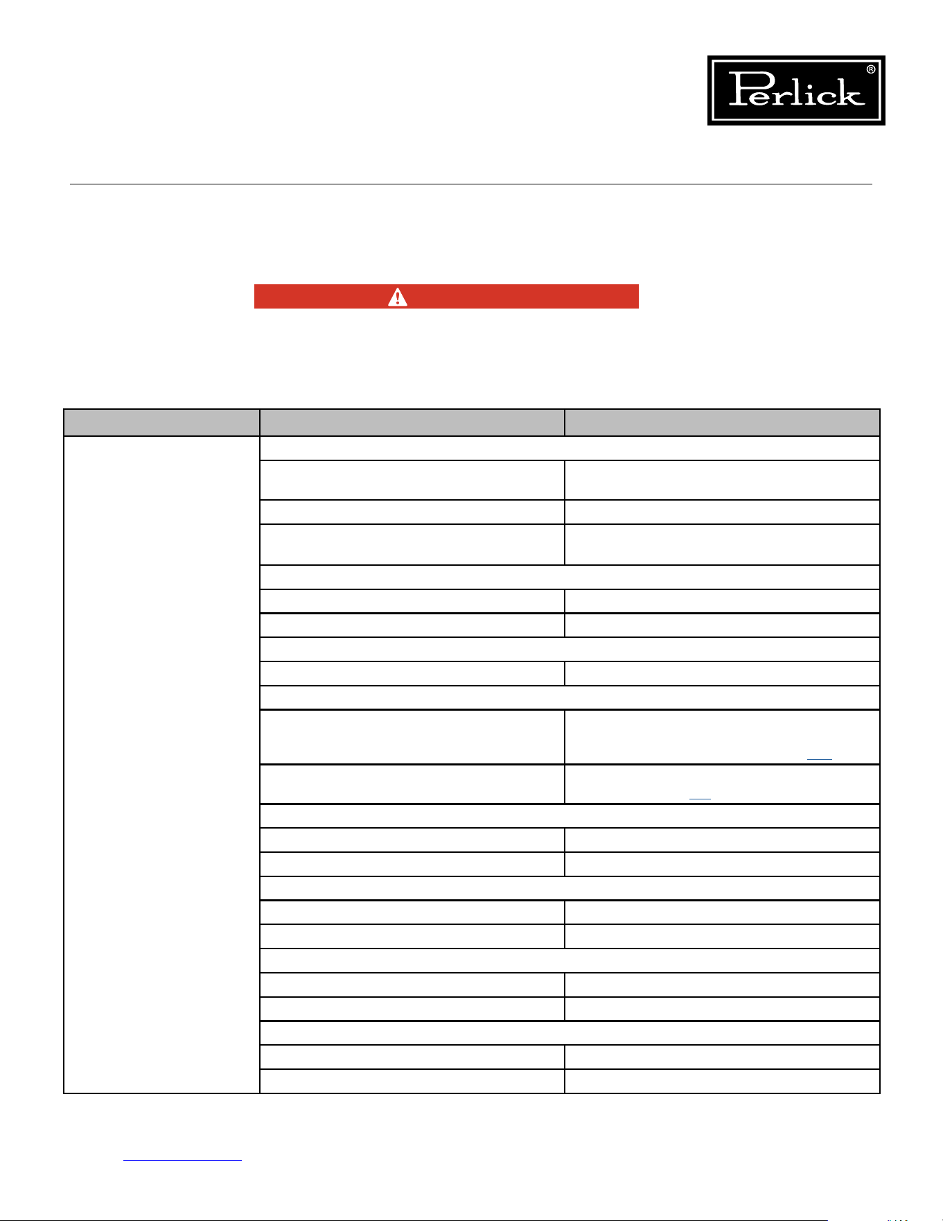
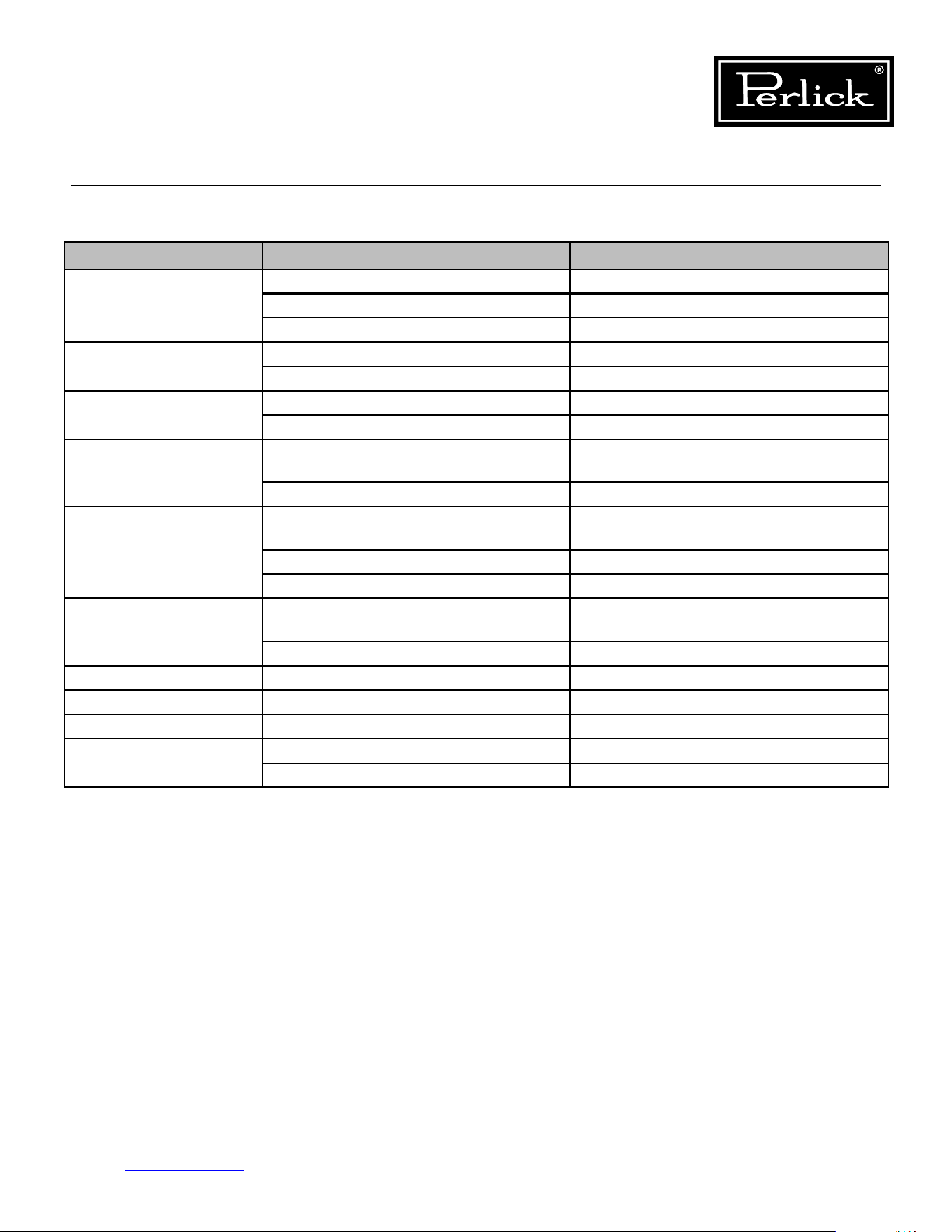
3.0 Troubleshooting Guide
3.1 Refrigeration System
Use this diagnostic guide to identify issues and to locate applicable instructions within this service manual.
This diagnostic guide can be used for any of Perlick’s Back Bar Refrigeration Products.
ELECTROCUTION HAZARD!!
Never attempt to repair or perform
maintenance on the unit until the Main
electrical power has been disconnected.
Table 3.1. Refrigeration System Diagnostics/Troubleshooting
PROBLEM CAUSE SOLUTION
Not Cooling Power Supply
Unplugged,o,blownfuse,trippedor
defective circuit breaker
Check for power at the receptacle
Loose Connection Check for continuity of wires
Power Requirements not within
specication
Verify that power at receptacle is the same
as nameplate rating
Cord and Plug
Loose Connection Check for continuity of wires
Defective Replace
Unit in Showroom Mode
Disable showroom mode See User Interface Section #.##
Internal Wiring
Loose Connection
Check for continuity or voltage at control
board (or check for heartbeat on control
board) See Control Board Section 7.1.
Miswired
Verify wiring by comparing to wiring
diagram Section 5.3.
Evaporator Fan Motor
Loose Connection Check Continuity or power at fan motor
Defective VerifyComponentSpecications
Condenser Fan Motor
Loose Connection Check Continuity or power at fan motor
Defective VerifyComponentSpecications
Evaporator
Clogged Remove Obstruction
Frozen De-Ice coil
Condenser
Airowobstructed Remove Obstruction
Dirty Condenser Verify condenser is clean
DANGER
Column Refrigeration Service Manual
Return to Table of Contents
14
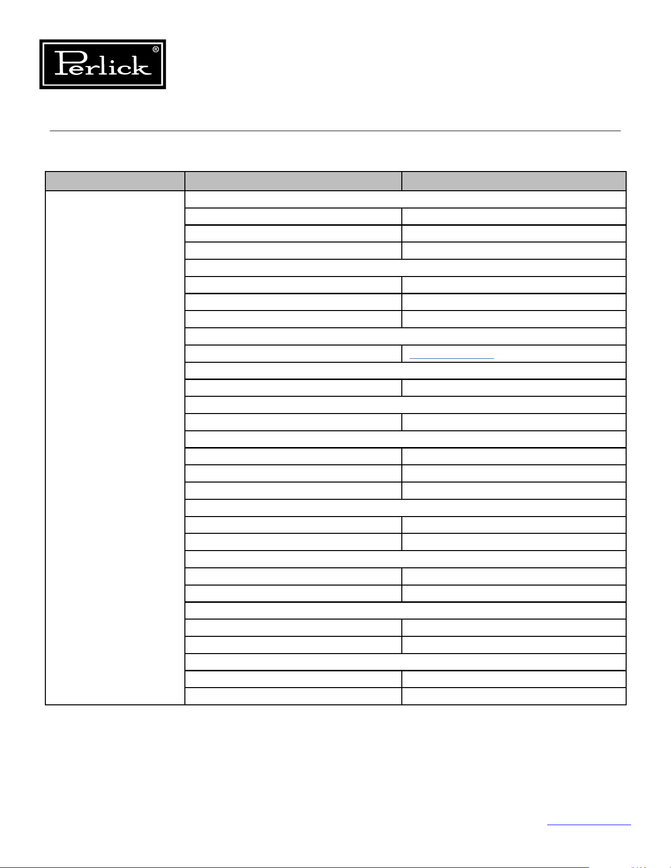
3.1 Refrigeration System (cont.)
Table 3.1. Refrigeration System Diagnostics/Troubleshooting
PROBLEM CAUSE SOLUTION
Not Cooling (cont.) Inverter
Loose Connection Check Connections
Power Ensure 120 power to inverter continuously
Signal Circuit Power Ensure Signal Circuit has power
Compressor
Open Windings Check continuity between pins
Locked Rotor Verify locked rotor
Internal Damage Verify Amperage
Refrigerant
Leak
See Section 6.11.
Refrigerant Circuit
Restriction Replace Refrigeration Module
Hot Gas Bypass Valve
Internal Leak Check Valve
Damper
Obstructed Remove Obstruction
Power Determine if damper is getting power
Defective Replace
Thermistors
Loose Connection Verify Continuity
Defective VerifyComponentSpecications
Temp/Humidity Sensor
Defective VerifyComponentSpecications
Loose Connection Verify Continuity
Control Board
Loose Connection Verify Continuity
Defective VerifyComponentSpecications
User Interface
Loose Connection Verify Continuity
Defective VerifyComponentSpecications
Column Refrigeration Service Manual
Return to Table of Contents
15
3.1 Refrigeration System (cont.)
Table 3.1. Refrigeration System Diagnostics/Troubleshooting
PROBLEM CAUSE SOLUTION
Evaporator Frozen Air Inltration
Access Hole Ensure access hole is sealed
with permagum
Module to Cabinet Seal Check for leaks between the refrigeration
module and cabinet
Door Left Open Ensure door closes properly
(hinges activated)
Door Gasket Seal Ensure door gasket integrity and it is
installed properly
Reed Switch Wire Hole Ensure reed switch wire hole is sealed
with permagum
Thermistors
Loose Connection Verify Continuity
Defective VerifyComponentSpecications
Temp/Humidity Sensor
Defective VerifyComponentSpecications
Loose Connection Verify Continuity
Evaporator
Dirty Clean
Defective VerifyComponentSpecications
Evaporator Fan Motor(s)
Fan Blades Binding Remove Obstruction
Defective Verify and Replace
Defrost Thermistor
Out of Position Install in proper location
Loose Connection Verify Continuity
Defective Verify and Replace
Hot Gas Solenoid Valve (Freezer Only)
Valve Stuck Verify and Replace Module
Coil Open Verify and Replace
Column Refrigeration Service Manual
Return to Table of Contents
16
3.1 Refrigeration System (cont.)
Table 3.1. Refrigeration System Diagnostics/Troubleshooting
PROBLEM CAUSE SOLUTION
Compartment Not
Holding Temperature
Check Setpoints
Incorrect Setpoint Adjust Setpoint
Thermistors
Loose Connection Verify Continuity
Defective VerifyComponentSpecications
Temp/Humidity Sensor
Defective VerifyComponentSpecications
Loose Connection Verify Continuity
Damper
Obstructed Remove Obstruction
Power Determine if damper is getting power
Defective Replace
Obstructed Airow
Checkairowinletandoutlet
for obstructions
Remove Obstruction
PROBLEM CAUSE SOLUTION
Noisy Operation Airow Noise
Condenser Fan Motors Airownoisefromthecondenserfans
is normal
Evaporator Fan Motors Airownoisefromtheevaporatorfans
is normal
Clicking/Crackling During Defrost
Solenoid Valve Normal during defrost
Frost/Ice Melting Normal during defrost
Metallic Noises
Tubes Isolate the tubes from surroundings
Sheet metal vibration Isolate the parts to prevent vibration
Compressor Noise
Normal Operation Some noise is normal from a
refrigeration compressor
Column Refrigeration Service Manual
Return to Table of Contents
17
3.2 Electrical System
Table 3.2. Electrical System Diagnostics/Troubleshooting
PROBLEM CAUSE SOLUTION
No Power To Cabinet Does Control board show Heartbeat? RedLEDoncontrolboardshouldash
like a heartbeat
Is control board receiving power? Check control connector P1 for
Power (115V)
Check Receptacle Cabinet is plugged in Tracebacktondwherepower
is interrupted
Check Power Cord Replace if defective
Check internal cabinet wiring Fix loose or disconnected terminals
Compressor Not Running Ensure unit is not in Showroom Mode Take unit out of Showroom mode
Control board compressor
LED illuminated
Green LED (LED2) should illuminate
continuously if calling for cooling
Evaporator Fans
not Running
Ensure unit is not in Showroom Mode Take unit out of Showroom mode
Control board Evap Fan LED
illuminated
Green LED (LED7) should illuminate
when call for Evap Fans
Check power at control board Connector P12 (Red to Black) 12VDC
Check power at fan terminal block 12VDC at block
Condenser Fans
not Running
Ensure unit is not in Showroom Mode Take unit out of Showroom mode
Control board Cond Fan
LED illuminated
Green LED (LED4) should illuminate when
call for Cond Fans
Check power at control board Connector P12 (Blue to Black) 12VDC
Check power at fan connectors 12VDC at connection
White Lights not Working
(Door Open)
Control Board White LED Illuminated Green LED (LED6) should illuminate when
call for white lights
Reed switch is open Check continuity of reed switch
(magnet on door)
Check power at control board Connector P13 (Orange to Black) 12VDC
Loose Connection Check connections
Column Refrigeration Service Manual
Return to Table of Contents
18
3.2 Electrical System (cont.)
Table 3.2. Electrical System Diagnostics/Troubleshooting
PROBLEM CAUSE SOLUTION
White Lights not Working
(Door Closed)
(Wine Units Only)
Is the unit in display mode? Ensure unit is in display mode
Reed switch is closed Check continuity of reed switch
(magnet on door)
Control Board White LED Illuminated Green LED (LED6) should illuminate when
call for white lights
Check Power at control board Connector P13 (Orange to Black) 12VDC
Loose Connection Check connections
Blue Light not Working
(Door Closed)
(Wine Units Only)
Is the unit in display mode? Ensure unit is in display mode
Is light intensity adjusted to Blue? Adjust Intensity to Blue
Reed switch is closed Check continuity of reed switch
(magnet on door)
Control Board Blue LED Illuminated Green LED (LED5) should illuminate when
call for blue lights
Check power at control board Connector P13 (Blue to Black) 12VDC
Loose Connection Check connections
Hot Gas Valve Solenoid
(Freezer Only)
Is unit in Defrost Mode Operates only when in defrost mode
Control Board LED Illuminated Green LED (LED3) should be illuminated
during defrost
Check power at control board Connector P12 (Yellow to Black) 12VDC
Check power at solenoid Should be 12VDC
Check Continuity of coil Coil resistance 11.1 ohms
Dampers Loose Connection Check connections
User Interface No Illumination Loose Connections
Door alarm activated Door Open Close Door
Missing/misaligned door magnet Align or install door magnet
Defective reed switch Evaluate and replace if defective
Column Refrigeration Service Manual
Return to Table of Contents
19
3.3 Doors, Drawers, Shelving
Table 3.3. Doors,Drawers,Shelving Diagnostics/Troubleshooting
PROBLEM CAUSE SOLUTION
Hinge Problems Improper Door Mounting Verify proper mounting.
Hinges not activated Activate Hinges
Excessive wear Replace Worn Parts
Door Handle Loose Improper Handle Mounting Verify proper mounting.
Excessive wear Replace Worn Parts
Overlay Loose Improper Overlay Installation Verify proper installation
Excessive wear Replace Worn Parts
Condensation On
Glass Doors
High ambient temperatures, high
humidity environmental conditions
Refer to Refrigeration System Repairs-
Ambient Temperatures
Frequent Door Openings Refer to Door, Drawers and Shelving
Key Won’t Come Out
Of Lock
Key not in proper position Rotate key to the proper position
and remove
Excessive wear Replace Worn Parts
Wrong Orientation Verify orientation
Push To Open Drawers Drawers won't open Verify push to open mechanisms
work properly
Drawers won't close Verify proper slide engagement
Tip-out Bin Operation Slides have disengaged from bin Re-engage the bin and troubleshoot
Slides/Stops misaligned Align Slides and spring steel stops
Shelving Full Extension Shelves disengage Verify proper slide engagement
Slides Noisy Lack of lubricant Lubricate slide with food grade lubricant
Debris in slides Clean and remove debris
Column Refrigeration Service Manual
Return to Table of Contents
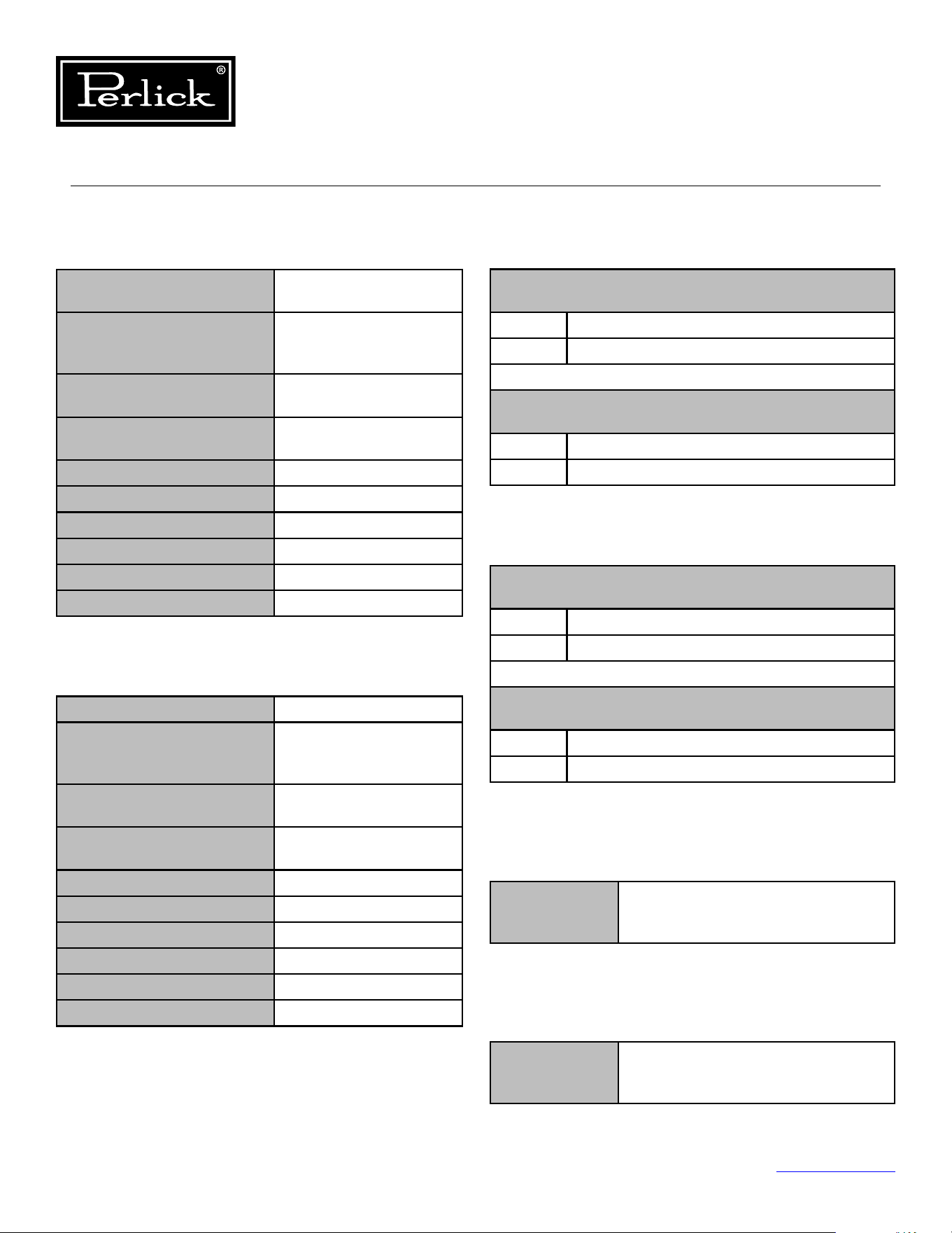
20
4.0 Electrical Components and Specications
4.2 Inverter 4.1 Compressor
Table 4.1.1. Compressor Specs (Model VEMX5C)
Table 4.1.2. Compressor Specs (Model VEMZ9C)
Table 4.2.1. Inverter Specs (Drop-In)
Table 4.2.2. Inverter Specs (Frequency Drive)
Table 4.3. Condenser Fan Motor Specs
Table 4.4. Evaporator Fan Motor Specs
4.1.1 MODEL: VEMX5C
Column Models CC24D, CC24W, CR24D,
CR24R, CR24W, CR30R
Type Variable Capacity (Speed)
Hermetic Reciprocating
Compressor
Nominal Voltage/
Frequency/ Phase
230V / 40-150Hz / 3 Ph
Refrigerant R-600a (Refrigerant
Grade Isobutane)
Commercial Designation 1/5 HP
Starting Device Type Inverter
Start Winding Resistance 16.07 (@ 77°F) +/-8%
Run Winding Resistance 16.07 (@ 77°F) +/-8%
Locked Rotor Amperage 2.10 A
Full Load Amperage 2.10 A
4.1.2 MODEL: VEMZ9C
Column Models CR24F
Type Variable Capacity (Speed)
Hermetic Reciprocating
Compressor
Nominal Voltage/
Frequency/ Phase
230V / 53-150Hz / 3 Ph
Refrigerant R-600a (Refrigerant
Grade Isobutane)
Commercial Designation 1/5 HP
Starting Device Type Inverter
Start Winding Resistance 16.07 (@ 77°F) +/-8%
Run Winding Resistance 16.07 (@ 77°F) +/-8%
Locked Rotor Amperage 2.10 A
Full Load Amperage 2.10 A
4.2.1: Drop-In
Model: EM
(Used with VEMX5C Compressor)
Input 115-127V AC / 50-60 HZ / 1 Ph / 3.3 A Max
Output 230V AC / 40-150 Hz / 3 Ph / 2.1 A
Model: VEMZ9C
(Used with VEMZ9C Compressor)
Input 115-127V AC / 50-60 HZ / 1 Ph / 3.3 A Max
Output 230V AC / 53-150 Hz / 3 Ph / 2.1 A
4.2.2 MODEL: Frequency Drive
Model: EM
(Used with VEMX5C Compressor)
Input 115-127V AC / 50-60 HZ / 1 Ph / 3.3 A Max
Output 230V AC / 40-150 Hz / 3 Ph / 2.1 A
Model: VEMZ9C
(Used with VEMZ9C Compressor)
Input 115-127V AC / 50-60 HZ / 1 Ph / 3.3 A Max
Output 230V AC / 53-150 Hz / 3 Ph / 2.1 A
4.3 Condenser Fan Motor
Specications 12VDC / 0.12A / 1.44W /
1.62 kOhms / 1600 RPM /
63.5 CFM / 27.0 dB
4.4 Evaporator Fan Motor
Specications 12VDC / 0.13A / 1.56W /
16.4 MOhms / 3700 RPM /
39.9 CFM / 3750 dB
Column Refrigeration Service Manual
Return to Table of Contents
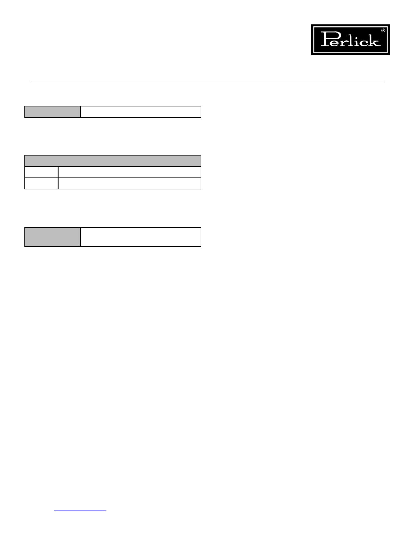
21
4.5 Hot Gas Defrost Solenoid Valve
4.6 Control
4.7 Damper
4.8 User Interface
Custom Design: Connect only to Perlick Column
Control Board
Table 4.5. Hot Gas Defrost Solenoid Valve Specs
Table 4.6. Control Specs
Table 4.7. Damper Specs
Coil Rating 12VDC, 15W, 1.08A, 11.1 ohms
Specications
Input 120V AC, 3.3A max
Output Various
Specications 12VDC, 0.5W,
1850 Step Stepper Motor
Column Refrigeration Service Manual
Return to Table of Contents
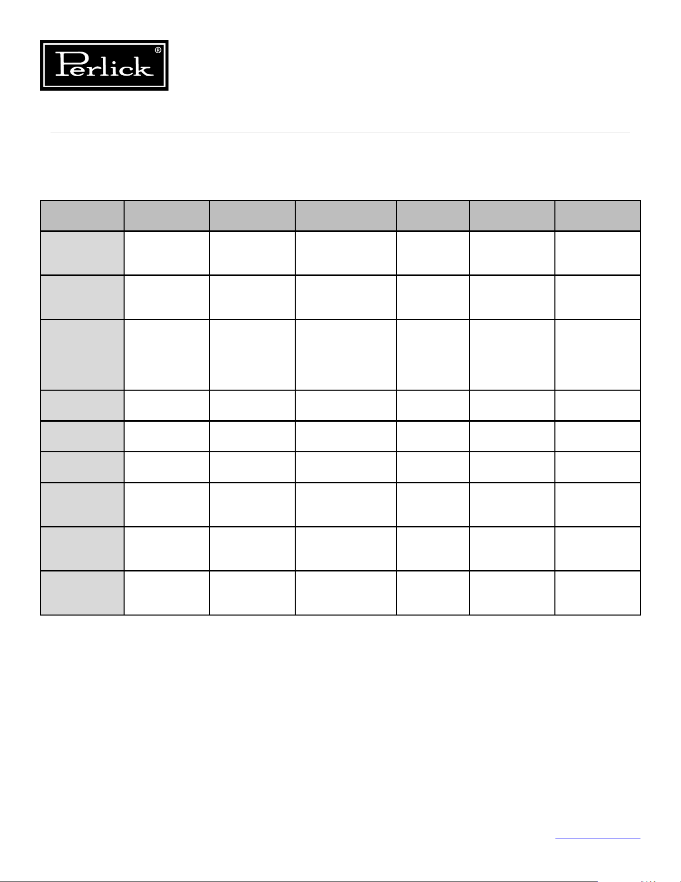
22
5.0 Component Operation
5.1 Modes Of Operation
Model: CR24R And CR30R
Component
Initial
Power-Up
Cooling
Mode (1)
Humidication
Mode (2)
O
Mode
Defrost
Mode (3)
Showroom
Mode
Control
Board
HeartBeat
Flashing Flashing Flashing Flashing Flashing Flashing
Lights
Activated with
Door Openings
Activated with
Door Openings
Activated with
Door Openings
Activated
with Door
Openings
Activated with
Door Openings
Activated with
Door Openings
Door Alarm
Activated with
Door Opening
(3 minute
delay)
Activated with
Door Opening
(3 minute
delay)
Activated with
Door Opening
(3 minute
delay)
Activated
with Door
Opening
(3 minute
delay)
Activated with
Door Opening
(3 minute
delay)
Activated with
Door Opening
(3 minute
delay)
Compressor
Delayed 3
Minutes
On O O O O
Condenser
Fan
Delayed 3
Minutes
On O O O O
Evaporator
Fan
Delayed 3
Minutes
On
Activated if
humidity required
O On O
Tip-Out
Produce Bin
Damper
Opening
Open until
satisedby
temperature
Open if humidity
required
Closed Closed Closed
Meat/Fish
Drawer
Damper
Opening
Open until
satisedby
temperature
Closed Closed Closed Closed
Deli Drawer
Damper
Opening
Open until
satisedby
temperature
Closed Closed Closed Closed
1. To avoid short cycling of the compressor there is a programmed 3-minute delay.
2. Upon the evaporator probe sensing 32°Fduringtheocycle,ahumidityreadingistakeninthetip-
out bin, if below desired humidity setpoint, tip-out bin damper opens and evaporator fans turn on.
3. Duringtheocycleaftereight(8)hourshaveelapsed,theunitgoesintoadefrostmodethathasthe
evaporator fan motors run for 10 minutes.
Table 5.1.1. Modes of Operation (CR24R)
Column Refrigeration Service Manual
Return to Table of Contents
23
5.1 Modes Of Operation
1. To avoid short cycling of the compressor there is a programmed 4-minute delay. Therefore, the
compressormustbeofor4minutesbeforeitwillstartthenextcoolingcycle.
2. Every eight (8) hours, the unit goes into a defrost mode that is timed (15 minutes) or evaporator coil
temperature (42°F) terminated. Upon termination of the defrost, the unit is idol for a 2 minute drip
(o)mode.Dependentuponcabinettemperature,theuniteithergoesintocoolingmodeorresumes
inomode.
Model: CR24F
Component
Initial
Power-Up
Cooling
Mode (1)
O
Mode
Defrost
Mode (2)
Showroom
Mode
Control
Board
HeartBeat
Flashing Flashing Flashing Flashing Flashing
Lights
Activated with
Door Openings
Activated with
Door Openings
Activated with
Door Openings
Activated
with Door
Openings
Activated with
Door Openings
Door Alarm
Activated with
Door Opening
(3 minute
delay)
Activated with
Door Opening
(3 minute
delay)
Activated with
Door Opening
(3 minute delay)
Activated
with Door
Opening
(3 minute
delay)
Activated with
Door Opening
(3 minute
delay)
Compressor
Delayed 4
Minutes
On O On O
Condenser
Fan
Delayed 4
Minutes
On O O O
Evaporator
Fan
Delayed 4
Minutes
On O O O
Defrost
Solenoid
O O O On O
Table 5.1.2. Modes of Operation (CR24F)
Column Refrigeration Service Manual
Return to Table of Contents
24
5.1 Modes Of Operation
Models: CR24W or CC24W
Component
Initial
Power-Up
Cooling
Mode (1)
Humidication
Mode (2)
O
Mode (4)
Defrost
Mode (3)
Showroom
Mode
Control
Board
HeartBeat
Flashing Flashing Flashing Flashing Flashing Flashing
Lights
Activated with
Door Openings
Activated with
Door Openings
Activated with
Door Openings
Activated
with Door
Openings
Activated with
Door Openings
Activated with
Door Openings
Door Alarm
Activated with
Door Opening
(3 minute
delay)
Activated with
Door Opening
(3 minute
delay)
Activated with
Door Opening
(3 minute delay)
Activated
with Door
Opening
(3 minute
delay)
Activated with
Door Opening
(3 minute
delay)
Activated with
Door Opening
(3 minute
delay)
Compressor
Delayed 3
Minutes
On O O O O
Condenser
Fan
Delayed 3
Minutes
On O O O O
Evaporator
Fan
Delayed 3
Minutes
On
Activated if
humidity required
O/On On O
1. To avoid short cycling of the compressor there is a programmed 3-minute delay.
2. Upon the evaporator probe sensing 32°Fduringtheocycle,acabinethumidityreadingistaken,if
below desired humidity setpoint, evaporator fans turn on until humidity setpoint is achieved. Then
unitresumesmovestoomode.
3. Duringtheocycleafter12hourshaselapsed,theunitgoesintoadefrostmodethathasthe
evaporator fan motors run for 10 minutes.
4. Duringtheocycle,theevaporatorfansareofor4minutesandthenonfor1minute,throughthe
durationoftheomode.
Table 5.1.3. Modes of Operation (CR24W/CC24W)
Column Refrigeration Service Manual
Return to Table of Contents
25
5.1 Modes Of Operation
Models: CR24D or CC24D
Component
Initial
Power-Up
Cooling
Mode (1)
Humidication
Mode (2)
O
Mode (4)
Defrost
Mode (3)
Showroom
Mode
Control
Board
HeartBeat
Flashing Flashing Flashing Flashing Flashing Flashing
Lights
Activated with
Door Openings
Activated with
Door Openings
Activated with
Door Openings
Activated
with Door
Openings
Activated with
Door Openings
Activated with
Door Openings
Door Alarm
Activated with
Door Opening
(3 minute
delay)
Activated with
Door Opening
(3 minute
delay)
Activated with
Door Opening
(3 minute delay)
Activated
with Door
Opening
(3 minute
delay)
Activated with
Door Opening
(3 minute
delay)
Activated with
Door Opening
(3 minute
delay)
Compressor
Delayed 3
Minutes
On O O O O
Condenser
Fan
Delayed 3
Minutes
On O O O O
Evaporator
Fan
Delayed 3
Minutes
On
Activated if
humidity required
O/On On O
Upper Zone
Damper
Opening
Open until
satisedby
temperature
Open if humidity
required
Closed/Open Closed/Open Closed
Lower Zone
Damper
Opening
Open until
satisedby
temperature
Open if humidity
required
Closed/Open Closed/Open Closed
1. To avoid short cycling of the compressor there is a programmed 3-minute delay.
2. Upon the evaporator probe sensing 32°Fduringtheocycle,upperandlowerzonehumidityreadings
are taken, if below desired humidity setpoint, evaporator fans turn on and respective damper(s) open
until humidity setpoint is achieved in each zone (dampers close up reaching zone humidity setpoint).
Thenunitresumesmovestoomode.
3. Duringtheocycleafter12hourshaselapsed,theunitgoesintoadefrostmodethathasthe
evaporator fan motors run for 10 minutes and the warmer setpoint damper open.
4. Duringtheocycle,theevaporatorfansareofor4minutesandthenonfor1minute,throughthe
durationoftheomode.
Table 5.1.4. Modes of Operation (CR24D/CC24D)
Electrical Specications
MODEL POWER
TYPE
VOLTAGE
(V)
CURRENT
(A)
FREQ
(Hz)
PHASE ELECTRICAL
CONNECTION
PLUG
CC24D AC 115 3.2 60 1 CORD CONNECTED NEMA 5-15P
CC24W AC 115 3.2 60 1 CORD CONNECTED NEMA 5-15P
CR24D AC 115 3.2 60 1 CORD CONNECTED NEMA 5-15P
CR24F AC 115 3.3 60 1 CORD CONNECTED NEMA 5-15P
CR24R
And
CR30R
AC 115 3.2 60 1 CORD CONNECTED NEMA 5-15P
CR24W AC 115 3.2 60 1 CORD CONNECTED NEMA 5-15P
Table5.2.ElectricalSpecications
Column Refrigeration Service Manual
Return to Table of Contents
26
5.2 Electrical Specications
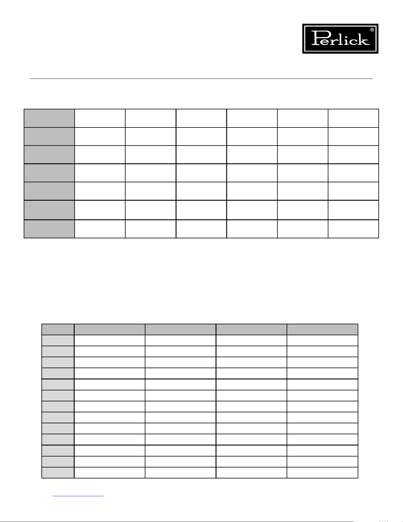
Column Temperature/Humidity Sensors
Model Temperature
Sensor 1
Temperature
Sensor 2
Temperature
Sensor 3
Temperature
Sensor 4
Temperature
Sensor 5
Temperature
Sensor 6
NTC Thermistor NTC Thermistor NTC Thermistor NTC Thermistor Temp/Humidity
Sensor
Temp/Humidity
Sensor
Refrigerator Main
Compartment
Deli Drawer Meat Drawer Evap Temp Produce
Drawer
Freezer Main
Compartment
Evap Temp
Single-Zone
Wine
Evap Temp Main
Compartment
Dual-Zone
Wine
Evap Temp Lower
Compartment
Upper
Compartment
Associated
Alarms
P1, L1, H1 P2, L2, H2 P3, L3, H3 P4, L4, H4 P5, L5, H5, R5 P6, L6, H6, R6
**NOTE: Alarm will stop once the cause of the alarm is corrected.
P1, P2, P3, P4, P5, P6 = Open/Disconnected NTC Thermistor or Temperature/Humidity Sensor
L1, L2, L3, L4, L5, L6 = Low Temperature Alarm (Sensed temperature is below X degrees F below setpoint for over
30 minutes)
H1, H2, H3, H4, H5, H6 = High Temperature Alarm (Sensed temperature is above X degrees F above setpoint for over
30 minutes)
r5, r6 = Open/Disconnected Humidity Sensor
d1 = door open alarm
Low/High Temperature Alarm Osets
Alarm Freezer Refrigerator Wine Single Zone Wine Dual Zone
L1 10°F below setpoint 6°F below setpoint
L2 6°F below setpoint
L3 6°F below setpoint
L4
L5 6°F below setpoint 6°F below setpoint 6°F below setpoint
L6 6°F below setpoint
H1 10°F above setpoint 6°F above setpoint
H2 6°F above setpoint
H3 6°F above setpoint
H4
H5 6°F above setpoint 6°F above setpoint 6°F above setpoint
H6 6°F above setpoint
Table 5.3. Control Alarms
Table5.4.Low/HighTemperatureAlarmOsets
Column Refrigeration Service Manual
Return to Table of Contents
31
5.4 Control Alarms
Column Refrigeration Service Manual
Return to Table of Contents
32
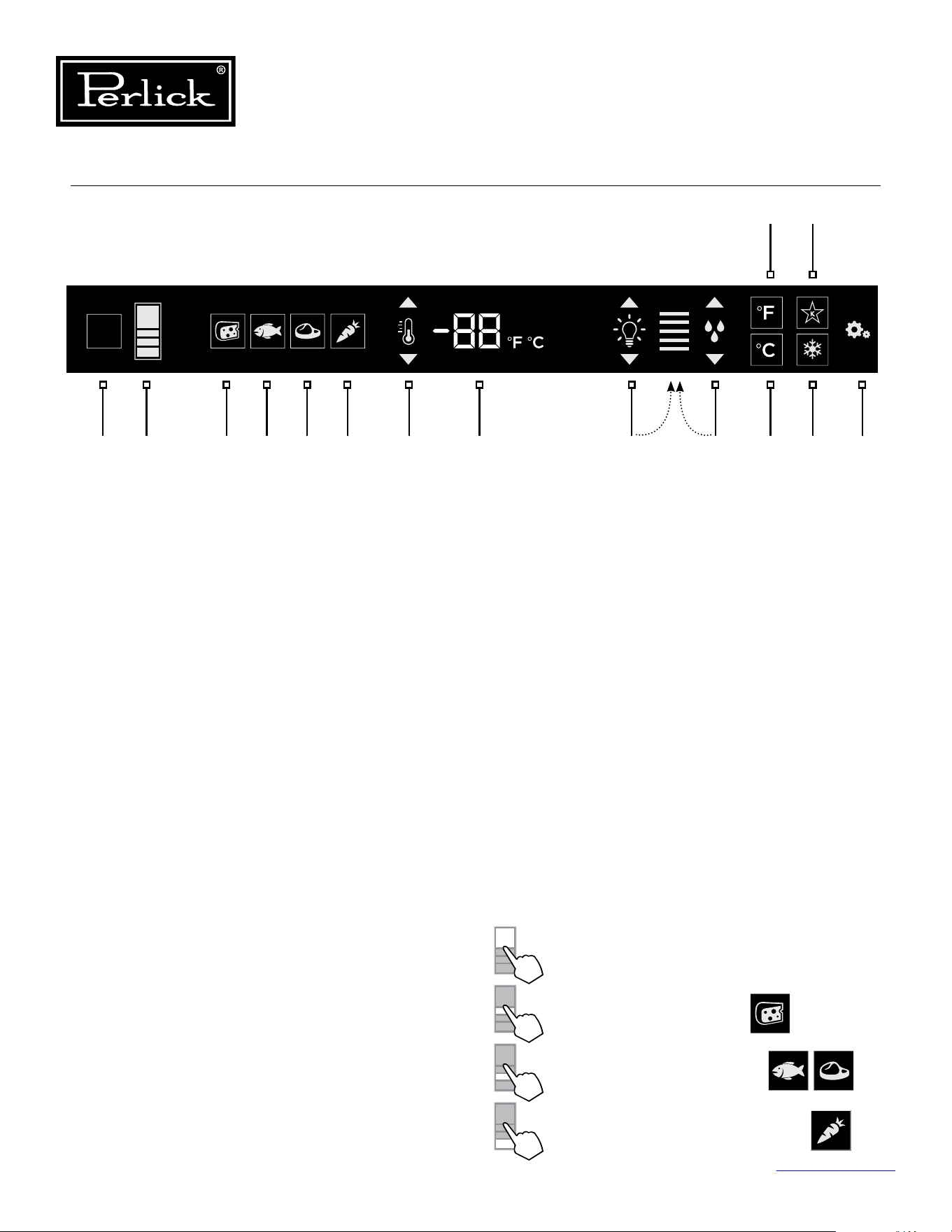
5.5 Refrigerator Control Operation
1. Wake Button
2. Temperature zone selection
3. Deli temperature setting
4. Fish/Seafood temperature setting
5. Meat temperature setting
6. Fresh Produce temperature setting
7. Temperature adjustment
(up and down in 1° increments)
8. Temperature readout
9. Light intensity adjustment
10. Humidity control adjustment
11. Fahrenheit temperature mode
12. Celsius temperature mode
13. Sabbath mode
14. QuickCool mode
15. Settings menu
5.5.1 Using the Refrigerator
Column Control
Upon door opening, the Wake button (1) outline
will illuminate. Once activated, the temperature
zone selection (2), temperature adjustment (7),
temperature readout (8) and settings (15) menu
icons will illuminate.
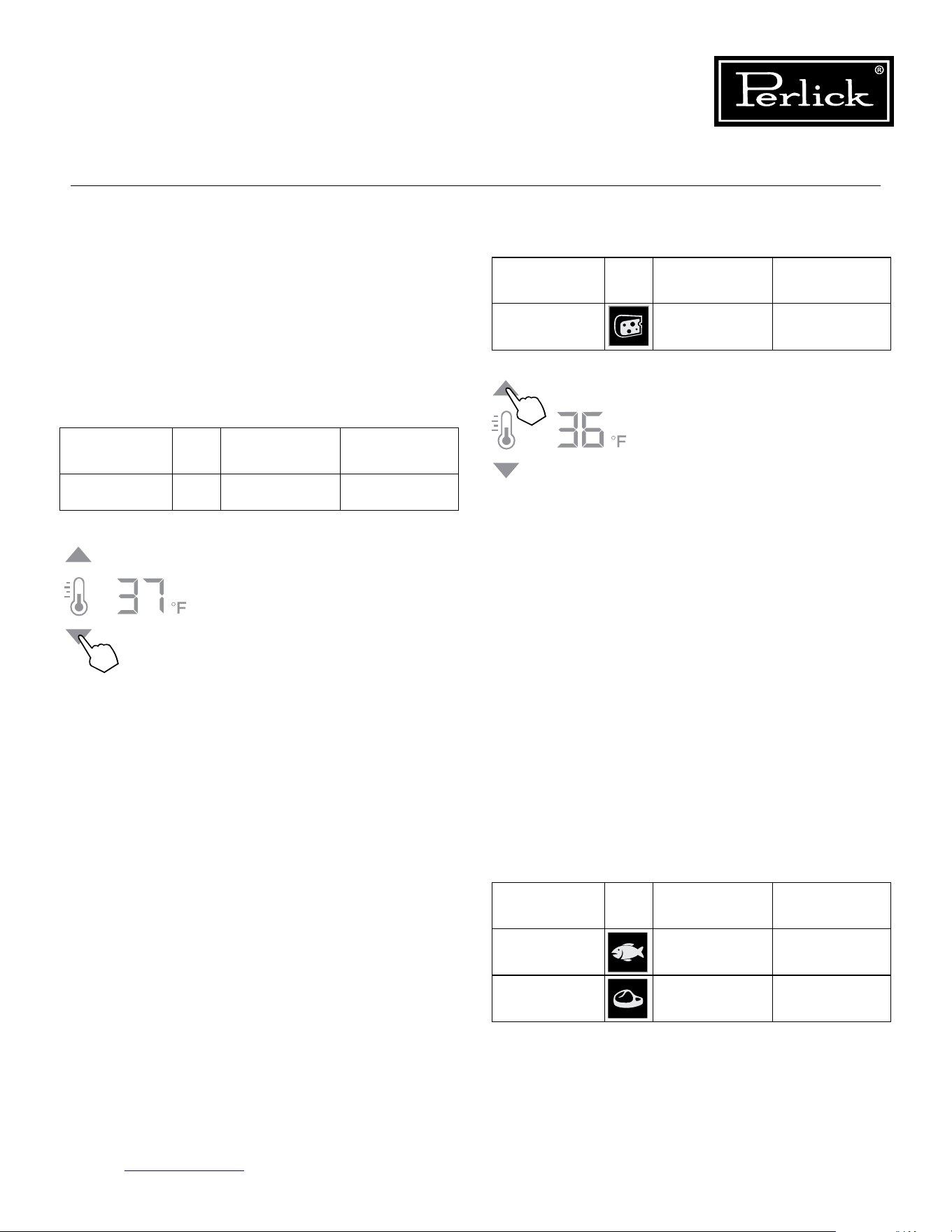
5.5.2 Selecting a Temperature Zone
Perlick’s touch-screen controller is preset with
recommended temperature settings for various
goods. Within these presets, you have the ability
to adjust the temperature in 1° increments as you
desire.
Press the temperature zone selection (2) icon to
toggle through the zones until desired zone is
illuminated. Zone and preset icon will illuminate to
prompt you to store certain goods in that particular
zone as shown below:
Control shown fully illuminated above for illustration purposes only.
2 3 4 5 6 7 8 9 10 12 14 151
11 13
Figure 5-2. Touch Screen Control
Main Compartment
Deli Drawer Compartment
Middle Drawer Compartment
Tip-Out Produce Bin Compartment
Column Refrigeration Service Manual
Return to Table of Contents
33
Compartment Sp. Factory Setting Temperature
Range
Middle 33°F 32°F - 37°F
Middle 35°F 32°F - 37°F
5.5.3 Main Compartment
The main compartment of the refrigerator features
two full-width shelves and a split shelf that can be
adjustedtottallitems.Becausethisisacommon
zonethatdoesn’tstorespecicitems,onlythe
temperature adjustment (7) and temperature
readout (8) will illuminate - no specialty
temperature settings (Sp.) will appear.
Compartment Sp. Factory Setting Temperature
Range
Main N/A 38°F 34°F - 42°F
The main compartment of the
refrigerator will come set from
the factory to 38°F. To adjust the
temperature up or down, press
the temperature adjustment (7)
arrows until desired temperature is
reectedinthetemperaturereadout
(8). Double keep indicates that
minimum or maximum temperature
has been reached. Temperature
willashtwicetoindicatethenew
setting.
5.5.4 Top Drawer Compartment
The deli compartment (top drawer) of the
refrigerator features a two-tier design for storing
and displaying charcuterie items such as artisan
meats and cheeses. When this zone is chosen,
the charcuterie (cheese) temperature setting (3),
temperature adjustment (7) and the temperature
readout (8) will illuminate.
Compartment Sp. Factory Setting Temperature
Range
Deli Drawer 33°F 32°F - 37°F
The two-tier charcuterie (deli)
drawer of the refrigerator will come
set from the factory at 33°F. To
adjust the temperature up or down,
press the temperature adjustment
(7) arrows until desire temperature
isreectedinthetemperature
readout (8). Double beep indicates
that the minimum or maximum
temperature has been reached.
Temperaturewillashtwiceto
indicate new setting.
5.5.5 Middle Drawer Compartment
The middle drawer compartment of the refrigerator
features a full-width drawer designed for storing
meat and seafood. When this zone is chosen, the
sh/seafood(sh)temperaturesetting(4),meat
(steak) temperature setting (5), temperature
adjustment (7) and temperature readout (8) will
illuminate.
Column Refrigeration Service Manual
Return to Table of Contents
34
The middle drawer compartment
of the refrigerator will come set
from the factory to 35°F (meat).
Ifstoringshorothertypesof
seafood,presstheshicontobring
the drawer to the preset mode of
33°F.
As with the other compartments,
you have the ability to raise or lower
the temperature in 1°F increments.
To adjust the temperature up
or down, press the temperature
adjustment (7) arrows until desired
temperatureisreectedinthe
temperature readout (8). Double
beep indicates that minimum or
maximum temperature has been
reached.Temperaturewillash
twice to indicate new setting.
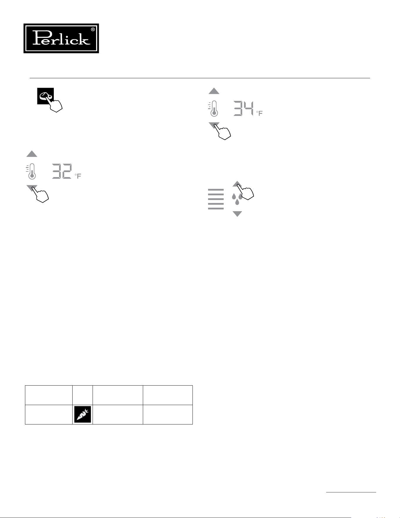
5.5.6 Bottom Drawer Compartment
The bottom drawer compartment of the
refrigerator features a unique tip out bin design
for storing fresh produce. When this zone is
chosen, the fresh produce (carrot) temperature
setting (6), temperature adjustment (7) and
temperature readout (8) will illuminate. In addition
to temperature-related icons, the humidity control
adjustment (10) icon will also illuminate.
Compartment Sp. Factory Setting Temperature
Range
Tip-out
Produce Bin
35°F 32°F - 37°F
As with the other compartments,
you have the ability to raise or lower
the temperature in 1°F increments.
To adjust the temperature up
or down, press the temperature
adjustment (7) arrows until desired
temperatureisreectedinthe
temperature readout (8).
The tip-out produce bin also
features a comprehensive humidity
system that delivers real moisture
based on your desired humidity
levels. This keeps produce such
as leafy greens fresher for longer.
The humidity is factory set to 80%,
but can be adjusted up and down
in 10% increments between 50%
and 90% by pressing the up or
down arrows in the humidity control
adjustment icon (10). The more
bars that illuminate, the higher
the humidity setting. Double beep
indicates that the minimum or
maximum level has been reached.
Iconswillashtwicetoindicatenew
setting.
Column Refrigeration Service Manual
Return to Table of Contents
35
5.5.7 Column Theater Lighting
Perlick column refrigerators feature an impressive
amount of lighting for clear viewing and display of
goods. Main lighting runs vertically down the walls
and horizontally across the ceiling of the main
compartment,delidrawer,meat/shdrawerand
tip-out produce bin.
5.5.9 Sabbath Mode
All Perlick column refrigeration models have
Sabbath mode capabilities. This allows the user to
interact with the unit without changing the amount
of energy it is using. In this mode, the interior
lightingisturnedountiluserturnsoSabbath
mode.
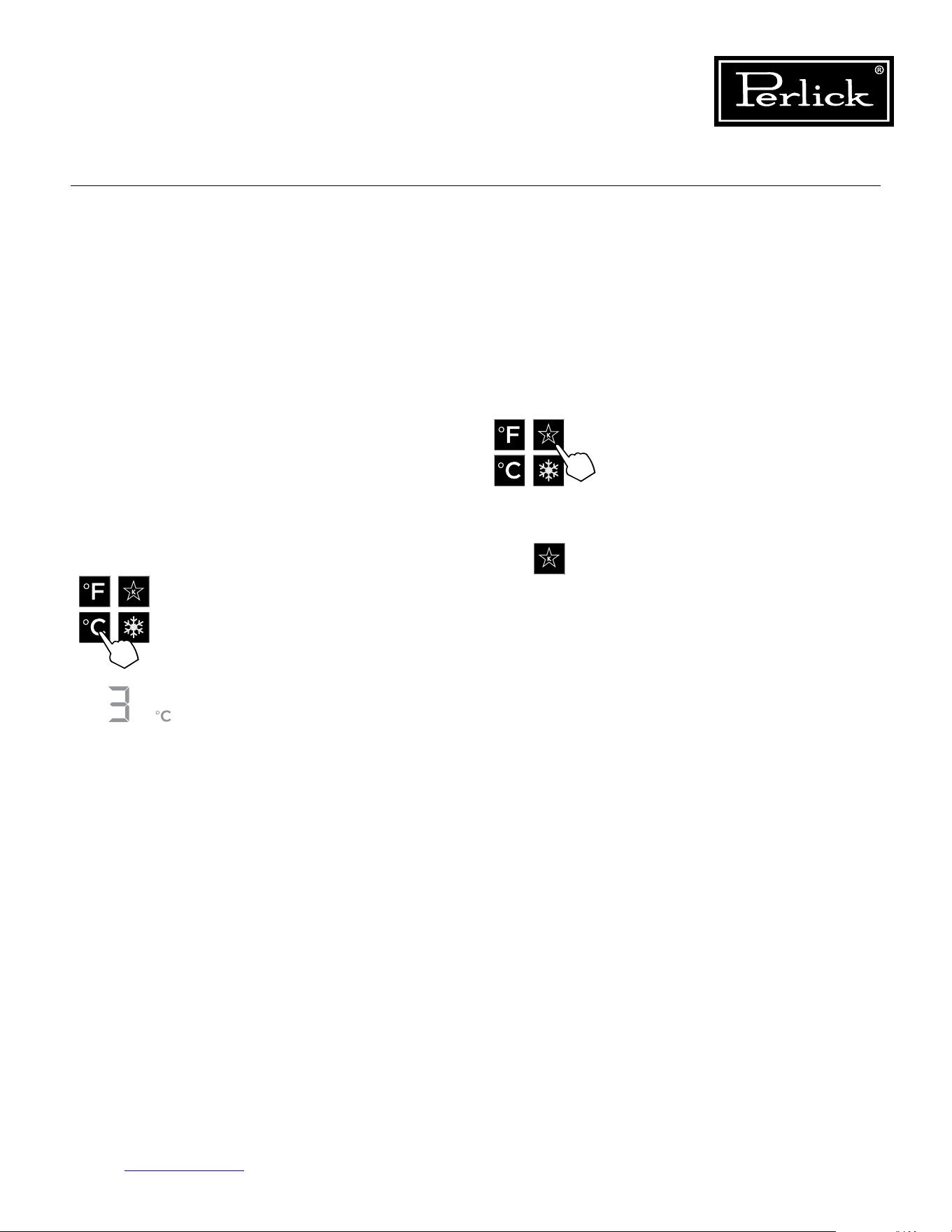
5.5.8 Changing From Fahrenheit To
Celsius Scale
The controller is factory set to Fahrenheit scale,
but can easily be changed to read Celsius in the
settings menu.
Press the settings menu (15) icon
on the far right. This will illuminate
a cluster of four icons as shown to
the left. To activate Sabbath mode,
press the Sabbath mode icon.
Please note that, when in Sabbath
mode, the Sabbath mode (13) icon
will be the only icon that will be
illuminated (continuously) until user
presses the Sabbath mode icon to
turnthemodeo.
Press the settings menu (15) icon
on the far right. This will illuminate
a cluster of four icons as shown to
the left. To display temperatures in
Celsius, press the Celsius readout
(12) icon.
Changewillbereectedinthe
temperature readout (8). The C will
be illuminated to signify the scale.
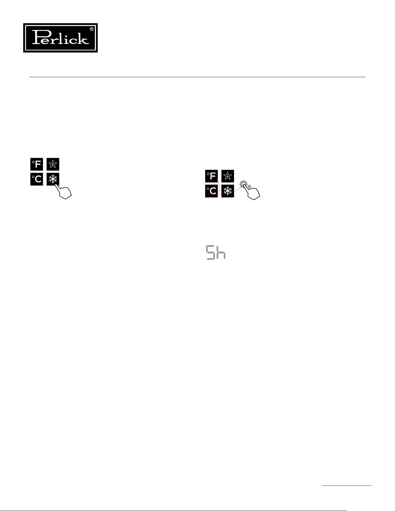
Column Refrigeration Service Manual
Return to Table of Contents
36
5.5.10 Quick Cool (Shopping) Mode
The main compartment of the refrigerator can
be set to Quick Cool (shopping) mode to lower
the temperature after loading a large quantity of
product to quickly bring them to the preferred
temperature.
5.5.11 Showroom Mode
Select Showroom mode for units that are being
used solely for display purposes. Showroom
mode has the user interface fully functional along
with the cabinet lights, however, no compressor,
evaporator fans or condenser fans will operate.
Press the settings menu (15) icon
on the far right. This will illuminate
a cluster of four icons as shown
to the left. A 5 key combination*,
including the Fahrenheit readout
(11) icon, Celsius readout (12) icon
and settings menu (15) icon, will
activate Showroom mode: F-C-F-C-
Settings. Upon activating showroom
mode, the temperature readout (7)
with show Sh each time the door
is opened until showroom mode is
turnedo.
To exit showroom mode, enter the
5 key combination.
*5 key combination must be
completed within 5 seconds to turn
showroommodeonando.
Press the settings menu (15) icon
on the far right. This will illuminate
a cluster of four icons as shown
to the left. To activate Quick Cool
(shopping) mode, press the Quick
Cool (14) icon. This will activate
the mode and the Quick Cool (14)
will remain illuminated until the set
point is achieved.
1
2 4
3
5
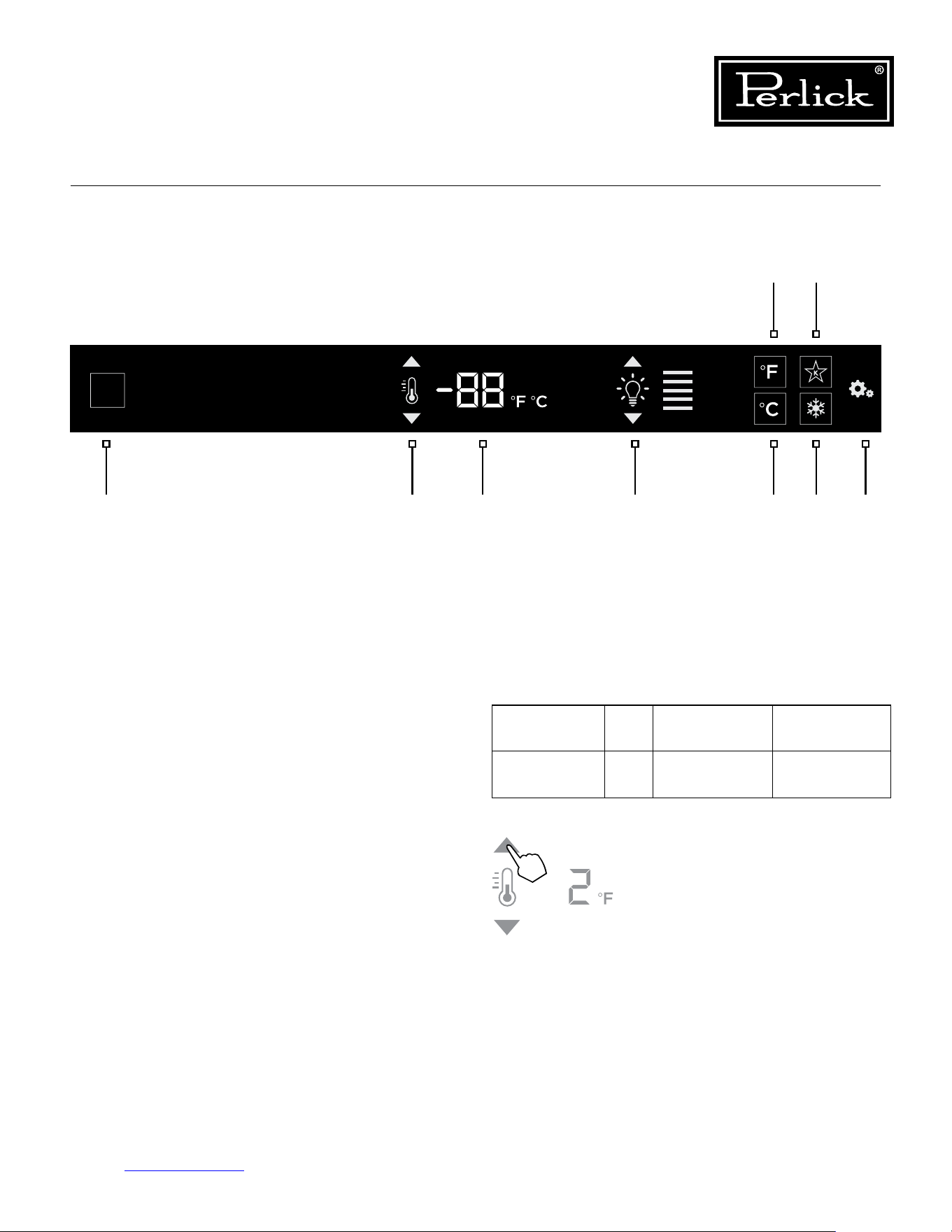
Column Refrigeration Service Manual
Return to Table of Contents
37
1. Wake Button
2. Temperature adjustment
(up and down in 1° increments)
3. Temperature readout
4. Light intensity adjustment
5. Fahrenheit readout
6. Celsius readout
7. Sabbath mode
8. Quick cool mode
9. Settings menu
5.6.2 Freezer Temperature
The freezer is the same temperature throughout,
so only the temperature adjustment (2) and
temperature readout (3) will illuminate.
5.6 Freezer Control Operation
The following instructions are for the touch-screen
control in Perlick column freezers (model CR24F).
Compartment Sp. Factory Setting Temperature
Range
All N/A 0°F -10°F - 10°F
5.6.1 Using the Freezer Column Control
Upon door opening, the Wake button (1) outline
will illuminate. Once activated, temperature
adjustment (2), temperature readout (3) and
settings (9) menu icons will illuminate.
The freezer will come set from
the factory to 0°F. To adjust the
temperature adjustment (2) arrows
untildesiredtemperatureisreected
in the temperature readout (3).
Double beer indicates that minimum
or maximum temperature has been
reached.Temperaturewillashtwice
to indicate new setting.
2 3 4 6 8 91
5 7
Control shown fully illuminated above for illustration purposes only.
Figure 5-3. Freezer Touch Screen Control
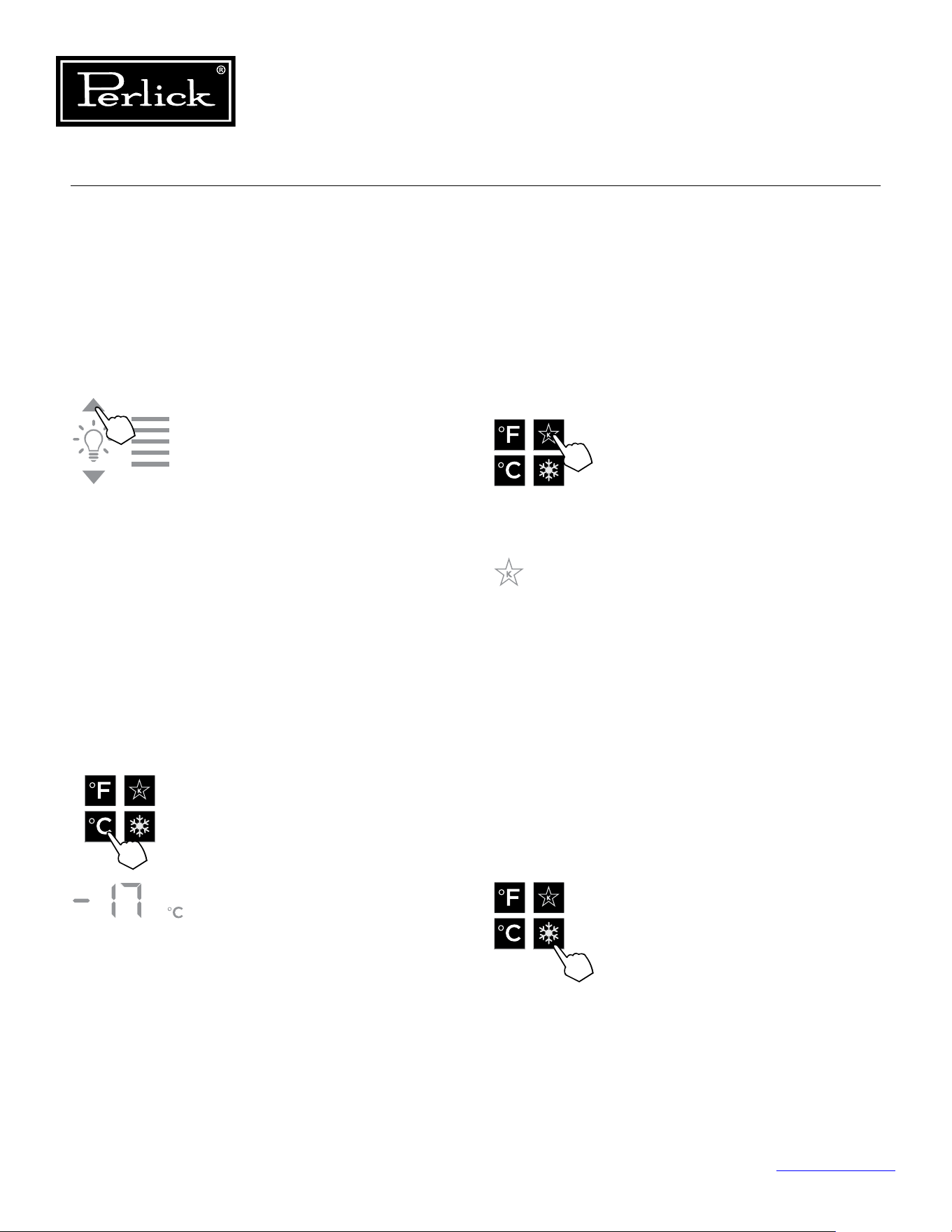
Column Refrigeration Service Manual
Return to Table of Contents
38
5.6.3 Column Theater Lighting
Perlick column freezers feature an impressive
amount of lighting for clear viewing and display of
goods. White LED lighting runs vertically down the
walls and horizontally across the ceiling of main
compartment.
To adjust the brightness of the
lighting when the door is opened,
press the up and down arrows in the
light intensity adjustment icon (4).
Double beep indicates that minimum
or maximum level has been reached.
Iconswillashtwicetoindicatenew
setting.
5.6.4 Changing From Fahrenheit To
Celsius Scale
The controller is factory set to Fahrenheit scale,
but can easily be changed to read Celsius in the
settings menu.
Press the settings menu (9) icon
on the far left. This will illuminate
a cluster of four icons as shown to
the left. To display temperatures in
Celsius, press the Celsius readout icon
(6).
Changewillbereectedinthe
temperature readout (3). The C will
be illuminated to signify the scale.
5.6.5 Sabbath Mode
All Perlick column refrigeration models have
Sabbath mode capabilities. This allows the user to
interact with the unit without changing the amount
of energy it is using. In this mode, the interior
lightingisturnedountiluserturnsoSabbath
mode.
Press the settings menu (9) icon on the
far right. This will illuminate a cluster
of four icons as shown to the left.
To activate Sabbath mode, press the
Sabbath mode icon (7).
Please note that, when in Sabbath
mode, the Sabbath mode (7) icon will
be the only icon that will be illuminated
(continuously) until user presses the
Sabbathmodeicontoturnthemodeo.
5.6.6 Quick Cool (Shopping) Mode
The main compartment of the freezer can be
set to Quick Cool (shopping) mode to lower the
temperature after loading a large quantity of
product to quickly bring them to the preferred
temperature.
Press the settings menu (9) icon on the
far right. This will illuminate a cluster
of four icons as shown to the left. To
activate Quick Cool (shopping) mode,
press the Quick Cool (8) icon. This will
activate the mode and the Quick Cool
(8) will remain illuminated until the set
point is achieved.
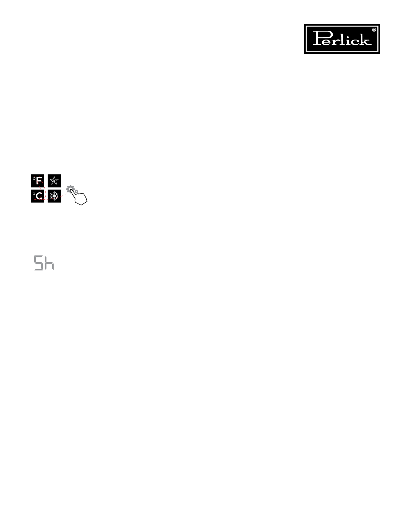
Column Refrigeration Service Manual
Return to Table of Contents
39
5.6.7 Showroom Mode
Select Showroom mode for units that are being
used solely for display purposes. Showroom
mode has the user interface fully functional along
with the cabinet lights, however, no compressor,
evaporator fans or condenser fans will operate.
Press the settings menu (9)
icon on the far right. This will
illuminate a cluster of four icons
as shown to the left. A 5 key
combination*, including the
Fahrenheit readout (5) icon,
Celsius readout (6) icon and
settings menu (9) icon, will
activate Showroom mode: F-C-
F-C-Settings. Upon activating
showroom mode, the temperature
readout (7) with show Sh each
time the door is opened until
showroommodeisturnedo.
To exit showroom mode, enter the
5 key combination.
*5 key combination must be
completed within 5 seconds to
turnshowroommodeonando.
1
2 4
3
5
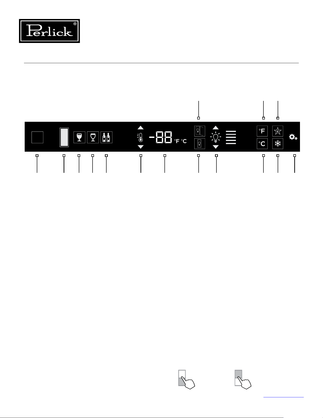
Column Refrigeration Service Manual
Return to Table of Contents
40
5.7 Wine Reserve Control Operation
The following instructions are for the touch-screen
control in Perlick column wine reserves (model
CR24W, CR24D, CC24W and CC24D).
1. Wake Button
2. Temperature zone selection (Dual-zone models)
3. White wine temperature setting
4. Red wine temperature setting
5. Cellar temperature setting
6. Temperature adjustment
(up and down in 1° increments)
7. Temperature readout
8. Light adjustment (door open)
9. Light adjustment (door closed)
10. Light intensity adjustment
11. Fahrenheit temperature mode
12. Celsius temperature mode
13. Sabbath mode
14. QuickCool mode
15. Settings menu
5.7.1 Using The Wine Column Control
Upon door opening, the Wake button (1) outline
will illuminate. Once activated, the temperature
zone selection (2), temperature adjustment (7),
temperature readout (8) and settings (15) menu
icons will illuminate.
5.7.2 Selecting A Temperature Zone
Perlick’s touch-screen controller is preset with
recommended temperature settings for white
wine, red wine and cellaring. Within the presets,
you have the ability to adjust the temperature in
1° increments as you desire. Because single zone
models (CR24W) are one temperature throughout,
there is no zone selection. On dual zone models
(CR24D), press the temperature zone selection (2)
icon to toggle through the zones until desired zone
is illuminated. Single zone models come factory
set to 50°F. Dual zone models come factory set to
60°F in the top zone and 50°F in the bottom zone.
2 3 4 5 6 7 109 12 14 151
11 13
8
Control shown fully illuminated above for illustration purposes only.
Figure 5-4. Wine Reserve Touch Screen Control
Top Zone
Bottom Zone
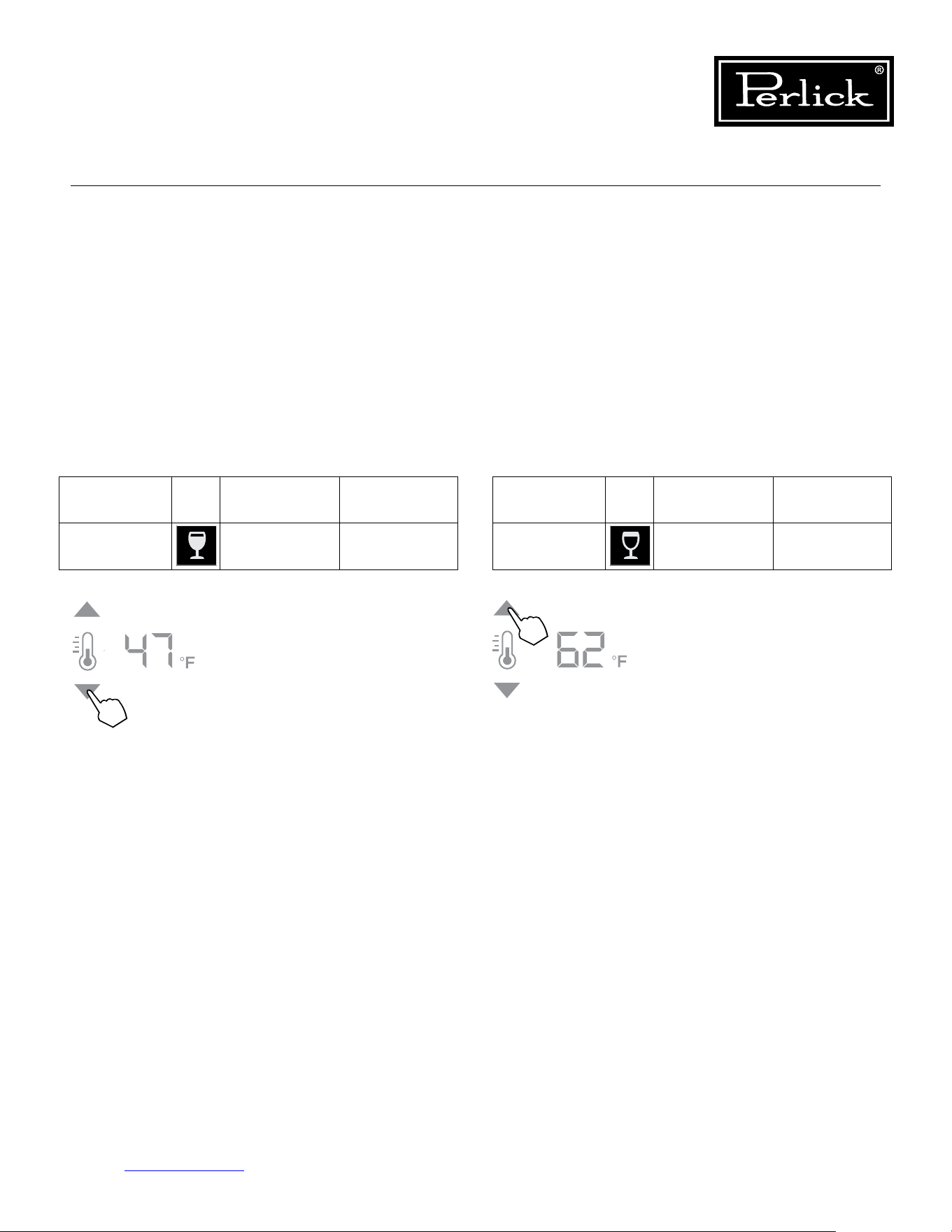
Column Refrigeration Service Manual
Return to Table of Contents
41
5.7.3 Storing White Wine
Perlick wine columns are preset with expert-
recommended temperature settings for white wine.
To set a zone in dual zone models to this preset,
touch the temperature zone selection icon (2)
to illuminate the zone you’d like to set to white
wine temperature, then choose the white wine
temperature setting icon (3) to set. For single zone
models, simply choose the white wine temperature
setting icon (3).
Compartment Sp. Factory Setting Temperature
Range
Any 50°F 40°F - 68°F
To adjust the temperature up
or down, press the temperature
adjustment (6) arrows until desired
temperatureisreectedinthe
temperature readout (7). Double
beep indicates that minimum or
maximum temperature has been
reached.Temperaturewillash
twice to indicate new setting.
5.7.4 Storing Red Wine
Perlick wine columns are preset with expert-
recommended temperature settings for red wine.
To set a zone in dual zone models to this preset,
touch the temperature zone selection icon (2)
to illuminate the zone you’d like to set to red
wine temperature, then choose the red wine
temperature setting icon (4) to set. For single zone
models, simply choose the red wine temperature
setting icon (4).
Compartment Sp. Factory Setting Temperature
Range
Any 60°F 40°F - 68°F
To adjust the temperature up
or down, press the temperature
adjustment (6) arrows until desired
temperatureisreectedinthe
temperature readout (7). Double
beep indicates that minimum or
maximum temperature has been
reached.Temperaturewillash
twice to indicate new setting.
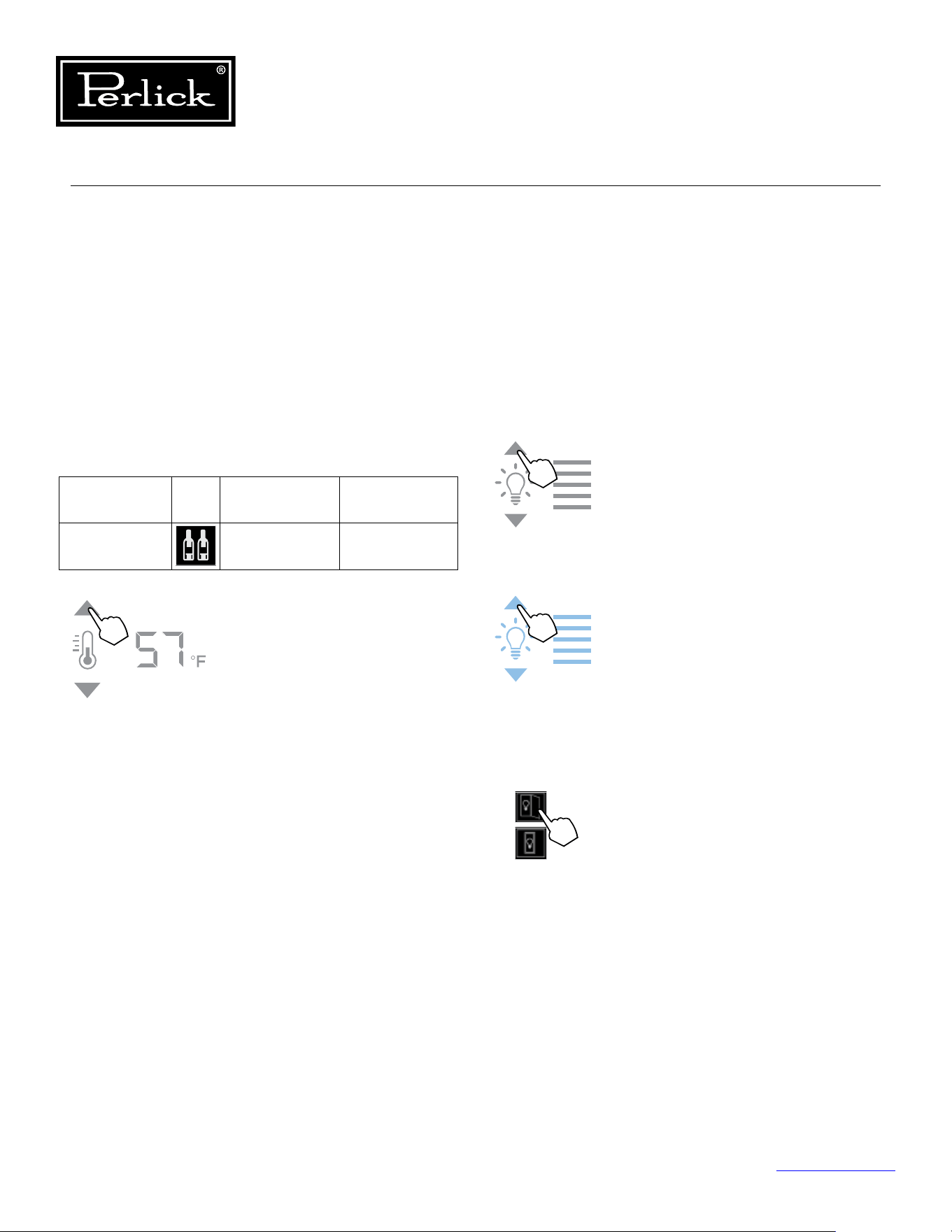
Column Refrigeration Service Manual
Return to Table of Contents
42
5.7.5 Cellaring Wine
Perlick wine columns are preset with expert-
recommended temperature settings for cellaring
(long-term storage) wine. By choosing the cellar
mode, the entire cabinet will default to 55°F for
long-term storage. For dual zone models, touch the
temperature zone selection icon (2) to illuminate,
then choose the Cellar temperature setting icon (5)
to set. For single zone models, simply choose the
Cellar temperature icon (5).
Compartment Sp. Factory Setting Temperature
Range
Any 55°F 40°F - 68°F
To adjust the temperature up
or down, press the temperature
adjustment (6) arrows until desired
temperatureisreectedinthe
temperature readout (7). Double
beep indicates that minimum or
maximum temperature has been
reached.Temperaturewillash
twice to indicate new setting.
5.7.6 Column Theater Lighting
Perlick column wine reserves feature an impressive
amount of lighting for clear viewing and display of
wine bottles. Door open white LED lighting runs
vertically down the walls and horizontally across
the ceiling of each compartment. Door closed
(display) lighting can be changed from white to
blue (blue will only illuminate the side walls.)
Wine models are factory set to white
lighting. To adjust the brightness of the
lighting when the door is opened, press
the up and down arrows in the light
intensity adjustment icon (4).
To change to blue lighting, continue
pressing the arrows until the control
turns blue in color (blue light only
illuminates when the door is closed.)
To return to white lighting, continue
pressing the arrows until controls
illuminatewhite.Iconswillashtwice
to indicate new setting.
Lighting adjustments can be made
separately for when the door is opened
and closed. Select the light adjustment
(door open) icon (8) to change the
intensity of the light when the door is
opened. Select the light adjustment
(door closed) icon (9) to change the
intensity or color of the light when
the door is closed. Please note that
when the door is open, the lights will
automatically go back to white for
visibility.
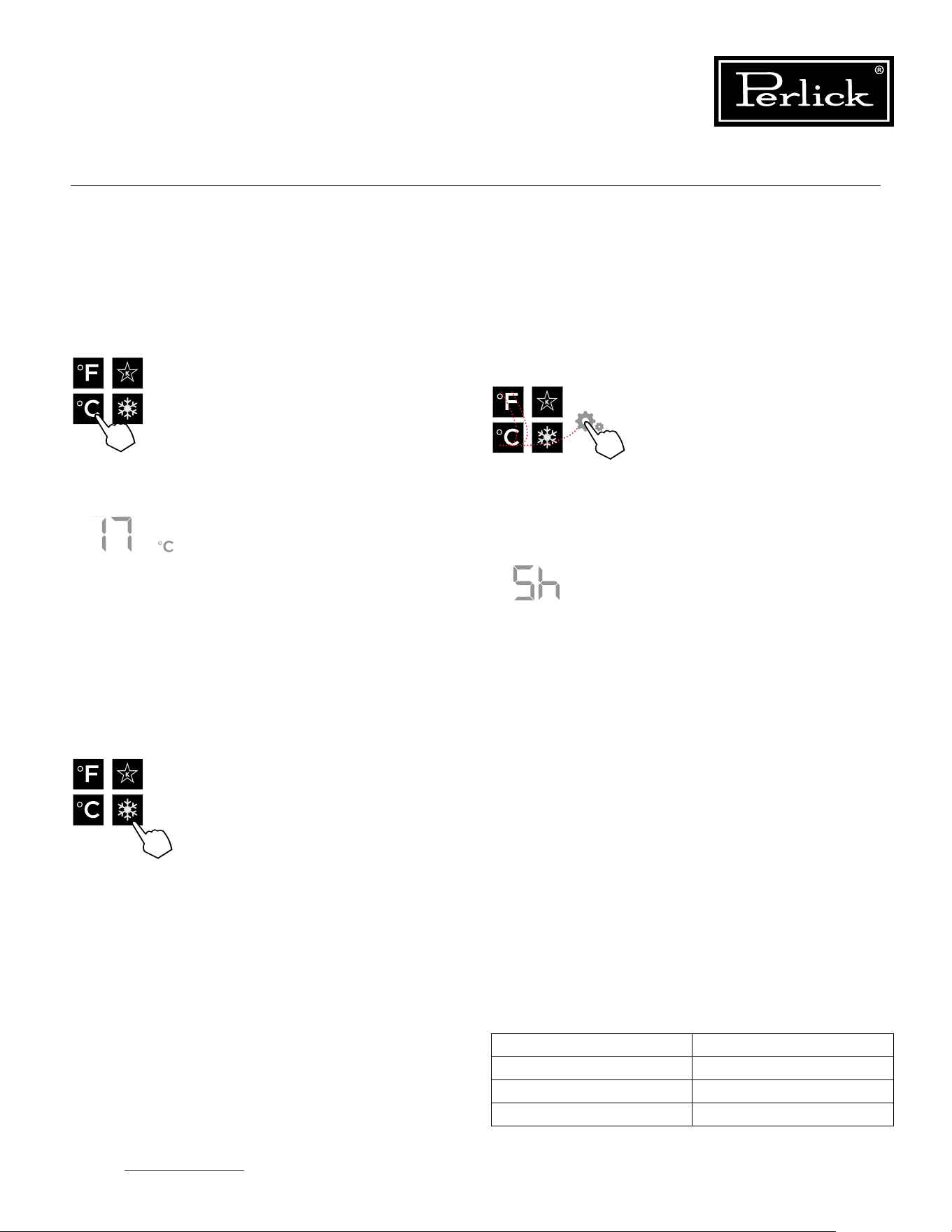
Ambient (F°) Relative Humidity (%)
70° 80%
80° 78%
90° 75%
Table 5.5. Ambient Conditions (Wine Reserve)
Column Refrigeration Service Manual
Return to Table of Contents
43
5.7.7 Changing From Fahrenheit To
Celsius Scale
The controller is factory set to Fahrenheit scale,
but can easily be changed to read Celsius in the
settings menu.
5.7.9 Showroom Mode
Select Showroom mode for units that are being
used solely for display purposes. Showroom
mode has the user interface fully functional along
with the cabinet lights, however, no compressor,
evaporator fans or condenser fans will operate.
Press the settings menu (15) icon
on the far right. This will illuminate
a cluster of four icons as shown to
the left. To display temperatures in
Celsius, press the Celsius readout
icon (12).
Changewillbereectedinthe
temperature readout (7). The C will
be illuminated to signify the scale.
5.7.8 Quick Cool (Shopping) Mode
The wine column can be set to Quick Cool
(shopping) mode to lower the temperature after
loading a large quantity of product to quickly bring
them to the preferred temperature.
Press the settings menu (15) icon
on the far right. This will illuminate
a cluster of four icons as shown
to the left. To activate Quick Cool
(shopping) mode, press the Quick
Cool (14) icon. This will activate
the mode and the Quick Cool (14)
will remain illuminated until the set
point is achieved.
Press the settings menu (15) icon
on the far right. This will illuminate
a cluster of four icons as shown
to the left. A 5 key combination*,
including the Fahrenheit readout
(11) icon, Celsius readout (12)
icon and settings menu (15) icon,
will activate Showroom mode:
F-C-F-C-Settings. Upon activating
showroom mode, the temperature
readout (7) will show Sh each time
the door is opened until showroom
modeisturnedo.
To exit showroom mode, enter the
5 key combination.
*5 key combination must be
completed within 5 seconds to turn
showroommodeonando.
5.7.10 Ambient Conditions
For units installed in areas with changing ambient
conditions, please take note of the table below. In
extreme conditions that exceed those listed below,
condensation may start to form on the front face of
the cabinet.
Condensation will subside as conditions return to
levels below those shown in the table.
1
2 4
3
5
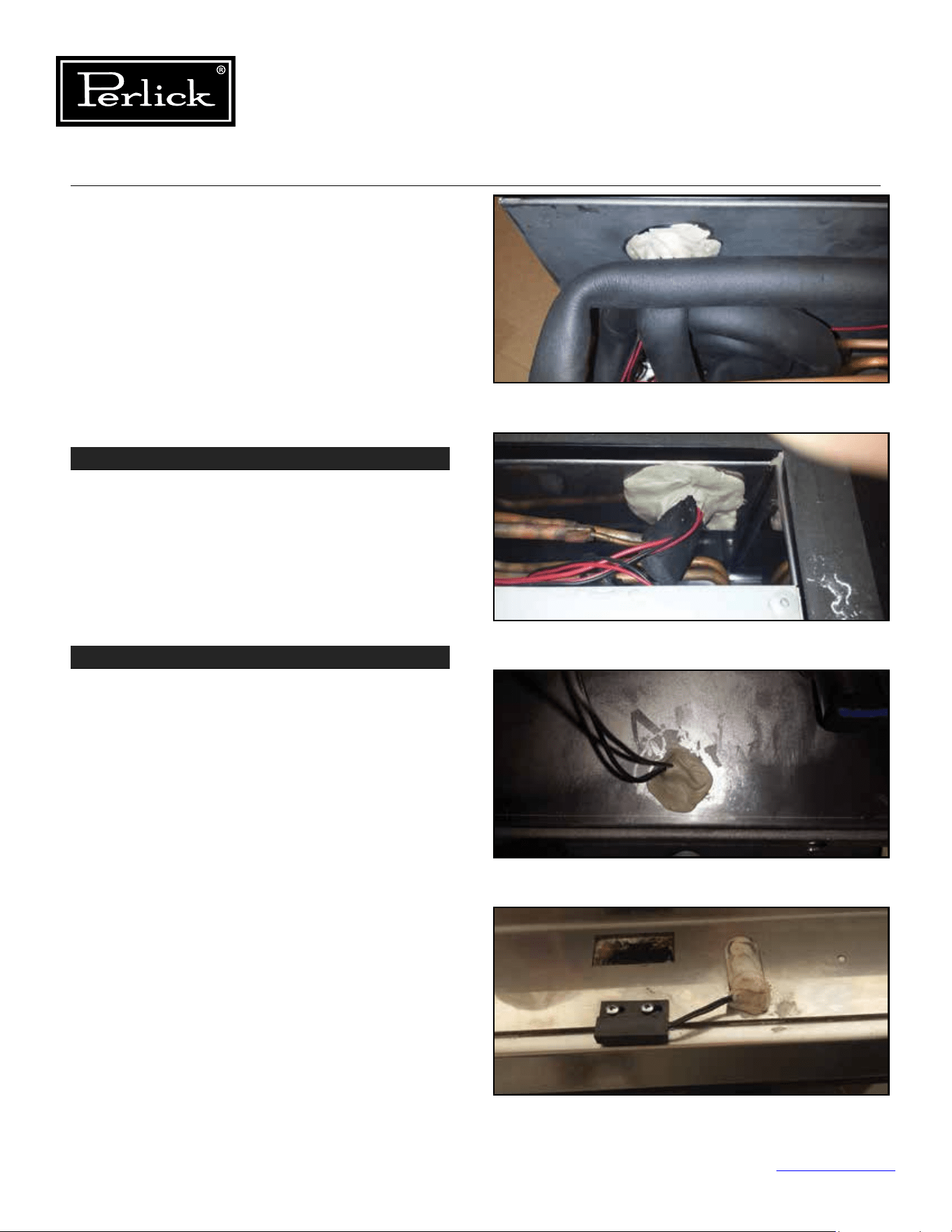
Column Refrigeration Service Manual
Return to Table of Contents
44
STEP 1 - Door Gaskets
Check door gaskets for rips, cracks, or other
damage.
Thedoorgasketshouldbepushedinrmlyandlay
at.
Ensure gasket forms a complete seal around the
door.
6.0 Refrigeration System Repair
6.1 Air Inltration
Airinltrationcanoccurinseverallocations.
NOTE: Unit may manifest longer than normal
run times caused by the additional loads that air
inltrationpresents.
Signsofairinltrationinclude:
• Presence of water, moisture or ice
• Condensation on glass or metal surfaces
STEP 2 - Sealing Compound
Sealing compound is used to seal wiring and line
set pass-through between the condenser and the
evaporator compartments.
See Figure 6-1.1 and
6-1.2.
Additionally, sealing compound is used to seal door
switch wiring pass-through holes at top of cabinet.
See Figure 6-1.3 and 6-1.4.
Check for voids and ensure sealing compound
completelyllsspace(bothoninteriorandexterior
openings (if both tubes and wires pass-through and
opening, ensure sealing compound is used between
the items).
Figure 6-1.1. Sealing Compound (Inside)
Figure 6-1.2. Sealing Compound (Outside)
Figure 6-1.3. Sealing Compound - Door Switch (Inside)
Figure 6-1.4. Sealing Compound - Door Switch (Outside)
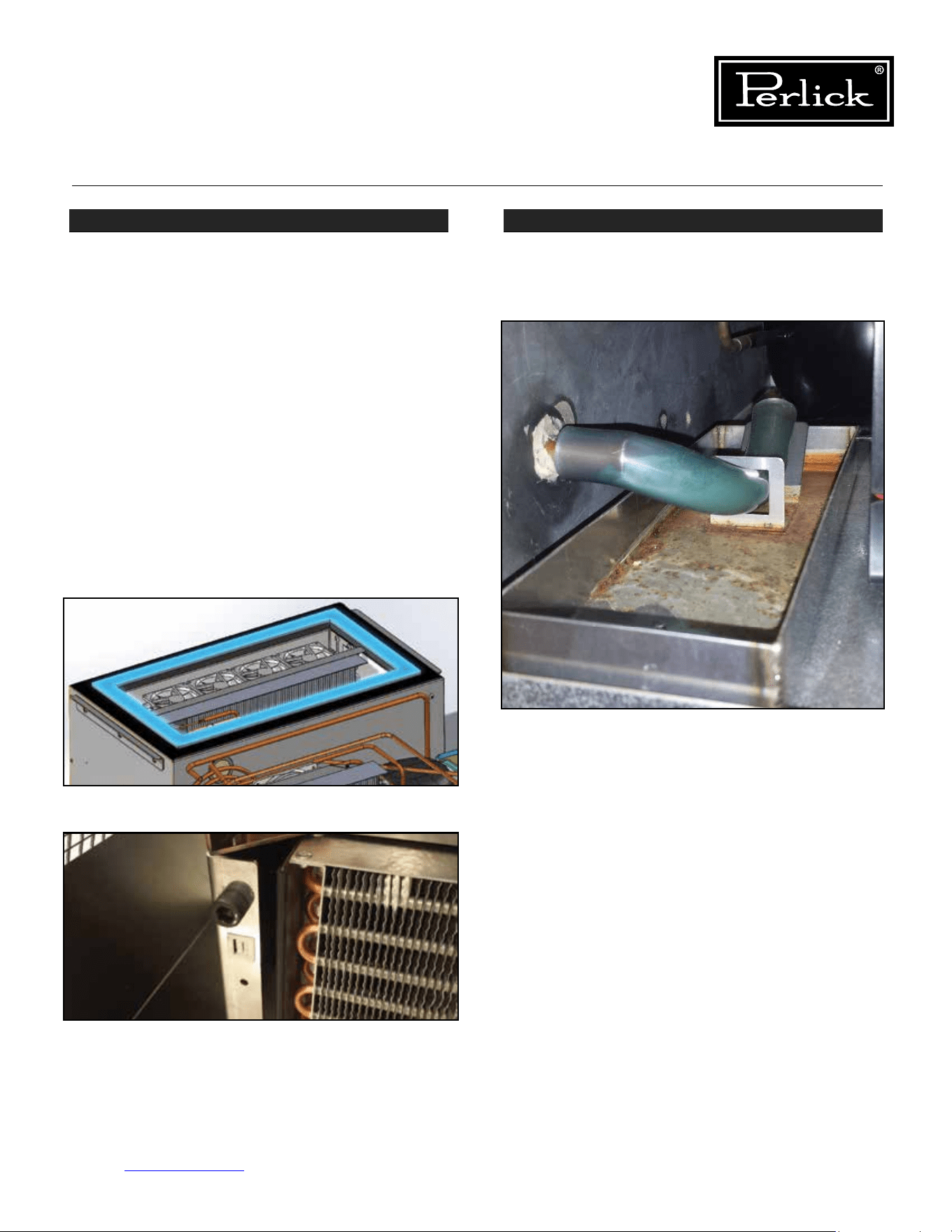
Column Refrigeration Service Manual
Return to Table of Contents
45
STEP 3 - Refrigeration Module Gasket
A gasket is used to seal between the refrigeration
module and the bottom of the cabinet.
See Figure
6-2.1.
Ensure refrigeration module is lifted tight against
the bottom of the cabinet using the refrigeration
module lift kit (lift bolts should be tight against
face of left and right cabinet machine compartment
endplates).
See Figure 6-2.2.
Check for condensation or cold air around the top
perimeter of the refrigeration module, or using a
bright light, shine the light at the gasket and look
for light on the other side of the gasket. If any
condensation, cold air or light can be detected
around the gasket, remove the refrigeration module
and inspect the gasket and replace. See section
Replace Refrigeration Module for details on how to
remove the module.
STEP 4 - Drain
Check that the evaporator condensate drain is
secure and connected.
See Figure 6-3.
Figure 6-2.1. Refrigeration Gasket
Figure 6-2.2. Lift Bolts
Figure 6-3. Evaporator Condensate Drain
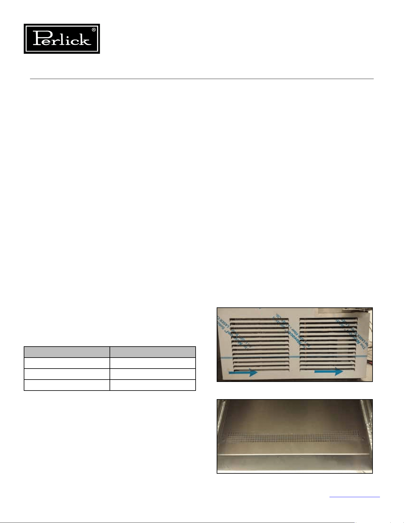
Ambient (F°) Relative Humidity (%)
70° 80%
80° 78%
90° 75%
Table 6.1. Ambient Conditions (Freezer)
Column Refrigeration Service Manual
Return to Table of Contents
46
6.2 Ambient Temperatures
• High ambient temperatures and high humidity
conditions may result in performance issues
and/or refrigeration system failure.
• These products are indoor rated products and
should never be exposed to direct weather.
• Do not subject the product to direct solar load.
• This equipment is not intended to be installed
directly adjacent to a heat source.
• Under extreme temperature and/or relative
humidity conditions, the front face, gasket and
glass door may show signs of condensation.
When the temperature and/or relative humidity
conditions return to normal, condensation will
disappear.
6.2.1 Freezer Ambient Conditions
For units installed in areas with changing ambient
conditions, please take note of the table below. In
extreme conditions that exceed those listed below,
condensation may start to form on the front face of
the cabinet.
Condensation will subside as conditions return to
levels below those shown in the table.
6.3 Air Flow Obstructions
• Theunitmusthavefreeairowtothe
front grill and to the evaporator intake and
discharge openings to operate properly.
Restrictedairowresultsinhighhead
pressuresandreductionineciencydueto
longerruntimes.Properairowthroughthe
condenser and evaporator is necessary for
ecientoperation.
• Neverobstructairowinandoutofthe
machine compartment. The front grill must be
free from obstructions, dust and debris.
See
Figure 6-4.1 and 6-4.2.
• Never obstruct the evaporator intake openings
or the discharge louvers or openings. Avoid
placing bagged or solid items at intake or
discharge openings.
See Figure 6-5.1. and
6-5.2
• Make sure higher temperature ambient air from
another unit is not directed to the condenser
coil (i.e. another heat source adjacent to or
directly across from the unit).
Figure 6-4.1. Grill/toe kick inlet and outlet
Figure 6-4.2. Evaporator Intake Openings
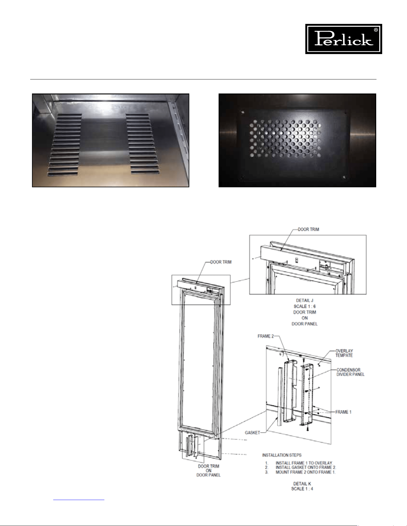
Column Refrigeration Service Manual
Return to Table of Contents
47
• Ensurethecondenserairowdivideris
installed on the lower interior portion
of the door. This divider prevents direct
circulation of machine compartment
air. If missing, unit will run extremely
inecientlyandextremehighdischarge
pressures and temperature which could
lead to compressor damage.
See Figure
6-6.
Figure6-6.CondenserAirowDivider
Figure 6-5.1. Evaporator Air Outlet Louvers Figure 6-5.2. Evaporator Air Damper Outlet Openings
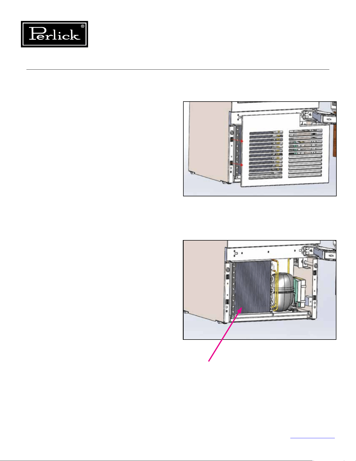
Column Refrigeration Service Manual
Return to Table of Contents
48
6.4 Condenser Coil Cleaning
• Perlick’s warranty does not cover cleaning of
the condenser coil.
• The condenser coil should be free obstruction,
dust and debris. The condenser coil should be
cleaned every 6 months or more or less often
dependent upon the environment.
To clean the condenser:
1. Open the door and remove the grill by pulling
away from the cabinet (grill is held on by four
(4) latch and mate connectors).
See Figure
6-7.1.
2. Once the grill is removed, using a soft brush
and vacuum, remove any dust or debris, being
carefultoavoiddamaging(bending)thenson
the condenser coil.
See Figure 6-7.2.
3. Once cleaned, reinstall the grill.
Figure 6-7.1. Remove Grill
Figure 6-7.2. Clean Condenser Coil
Condenser Coil
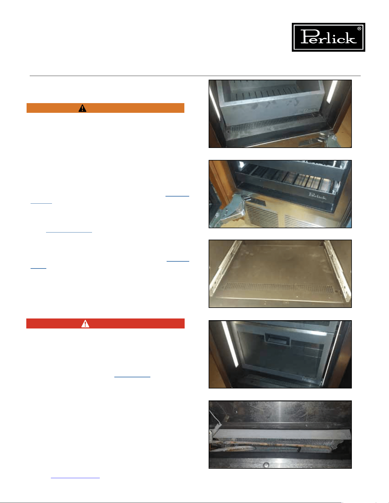
Column Refrigeration Service Manual
Return to Table of Contents
49
6.5 De-Ice Blocked Evaporator Coil
Use towels to absorb water to avoid damage to
themachinecompartmentorsurroundingooring.
Machine compartment condensate pan may
overowifmanuallydefrostedwithouttheuseof
towels.
1. Unplugorturnopowertotheunit.
To access the evaporator:
Freezer: Remove the bottom drawer (
see Section
8.14.2.
) and then remove the false inner liner
bottom panel.
See Figure 6-8.
Wine: Remove the bottom two or three shelves
(
see Section 8.16.1.
) and then remove the false
inner liner bottom panel.
See Figure 6-9.1 and
6-9.2.
Refrigerator: Remove the tip-out bin (
see Section
8.13.
) and then remove the false inner liner bottom
panel.
See Figure 6-10.
2. Using a fan or heat gun, direct warm air over
the coil to melt the ice.
See Figure 6-11.
NEVER USE TOOLS OR SHARP OBJECTS
TO CHIP OR REMOVE ICE FROM THE
EVAPORATOR OR TUBES.
3. Once ice has been removed, review air
inltrationsection(seeSection 6.1.).
4. Reinstall components removed reversing the
removal instructions.
WARNING
Figure 6-8. Freezer Drawer
Figure 6-9.1. Wine Shelves
Figure 6-10. Tip-Out Bin/Inner Liner
Figure 6-11. Evaporator Coil
DANGER
Figure 6-9.2. Bottom Shelves/Bottom Panel
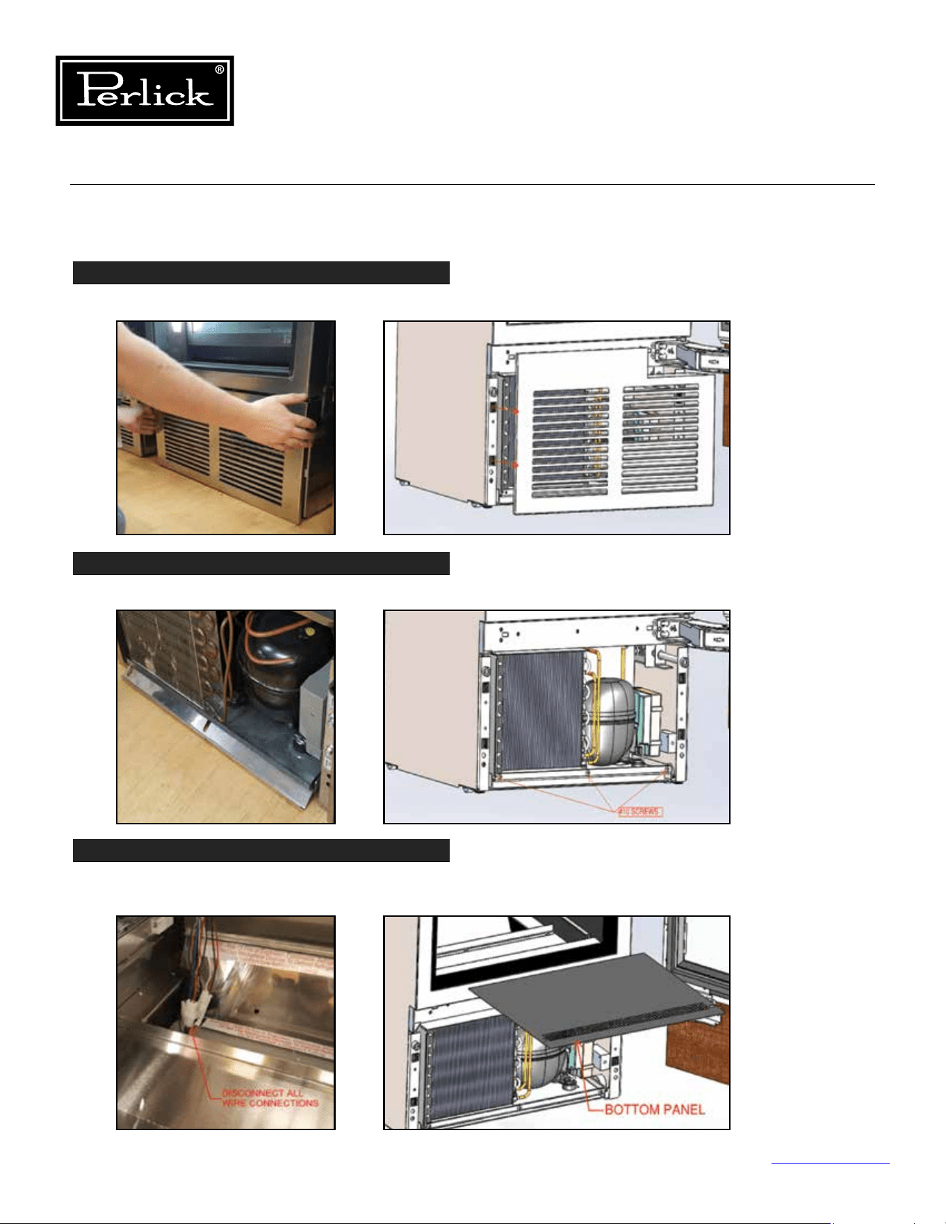
Column Refrigeration Service Manual
Return to Table of Contents
50
6.6 Replace Refrigeration Module
STEP 1
Remove the grill by pulling it directly away from the cabinet.
STEP 2
Remove front lift bracket by removing (3) #10 sheet metal screws.
STEP 3
Disconnect the refrigeration module wiring by removing the bottom panel in the cabinet.
Shelves or drawers will need to be removed to access the bottom of the cabinet.
Figure 6-12.1. Remove Grill
Figure 6-12.2. Remove Lift Bracket
Figure 6-12.3.
Disconnect
Refrigeration
Wiring
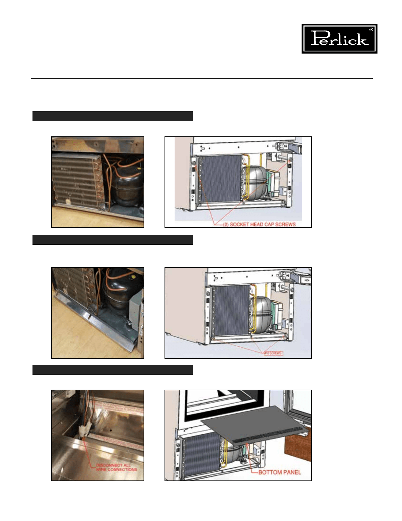
Column Refrigeration Service Manual
Return to Table of Contents
51
6.6 Replace Refrigeration Module (cont.)
STEP 4
Using a 3/8” allen wrench, lower the refrigeration module by loosening (2) socket head cap screws.
STEP 5
Once module is lowered and all wires disconnected, slide module out by pulling on the vase
panelofthemodule.Protecttheoorinfrontoftheunittopreventscratchestotheoor.
STEP 6
Disconnect the power cord from the rear of the unit after the refrigeration module is removed.
Figure 6-12.4.
Lower
Refrigeration
Module
Figure 6-12.5.
Slide
Refrigeration
Module Out
Figure 6-12.6.
Disconnect
Power Cord
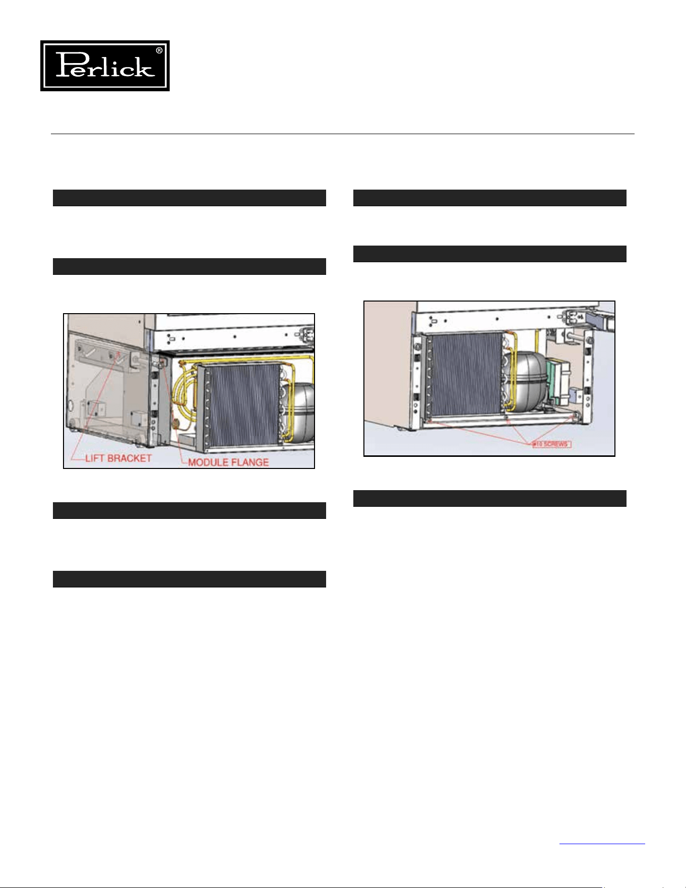
Column Refrigeration Service Manual
Return to Table of Contents
52
6.6 Replace Refrigeration Module (cont.)
STEP 7
To replace the refrigeration module, reconnect the
power cord to the new unit. Reference Step 6,
where the power cord was disconnected.
STEP 8
Positionthemoduleangesontotheliftbrackets
and slide the unit into the cabinet until it stops.
STEP 9
Raise the refrigeration module into place by
tightening the socket head cap screws using a
3/8” allen wrench.
STEP 10
Reconnect all wiring from the refrigeration module
and cabinet. The wires from the cabinet and
module are color coded to match one another.
Before proceeding to Step 11, make sure unit is
functioning as intended. If not, ensure all wires
are tightly secured.
STEP 11
Install the cabinet bottom panel and any drawers
or shelves removed in Step 3.
STEP 12
Reinstall the front lift bracket to the module using
the (3) #10 screws removed in step 2.
STEP 13
Reinstall the grill. Make sure latches are aligned
with the catches on each side of the unit before
pushing grill onto cabinet.
Figure 6-12.7. Slide Unit Back Into Cabinet
Figure 6-12.8. Reinstall Front Lift Bracket
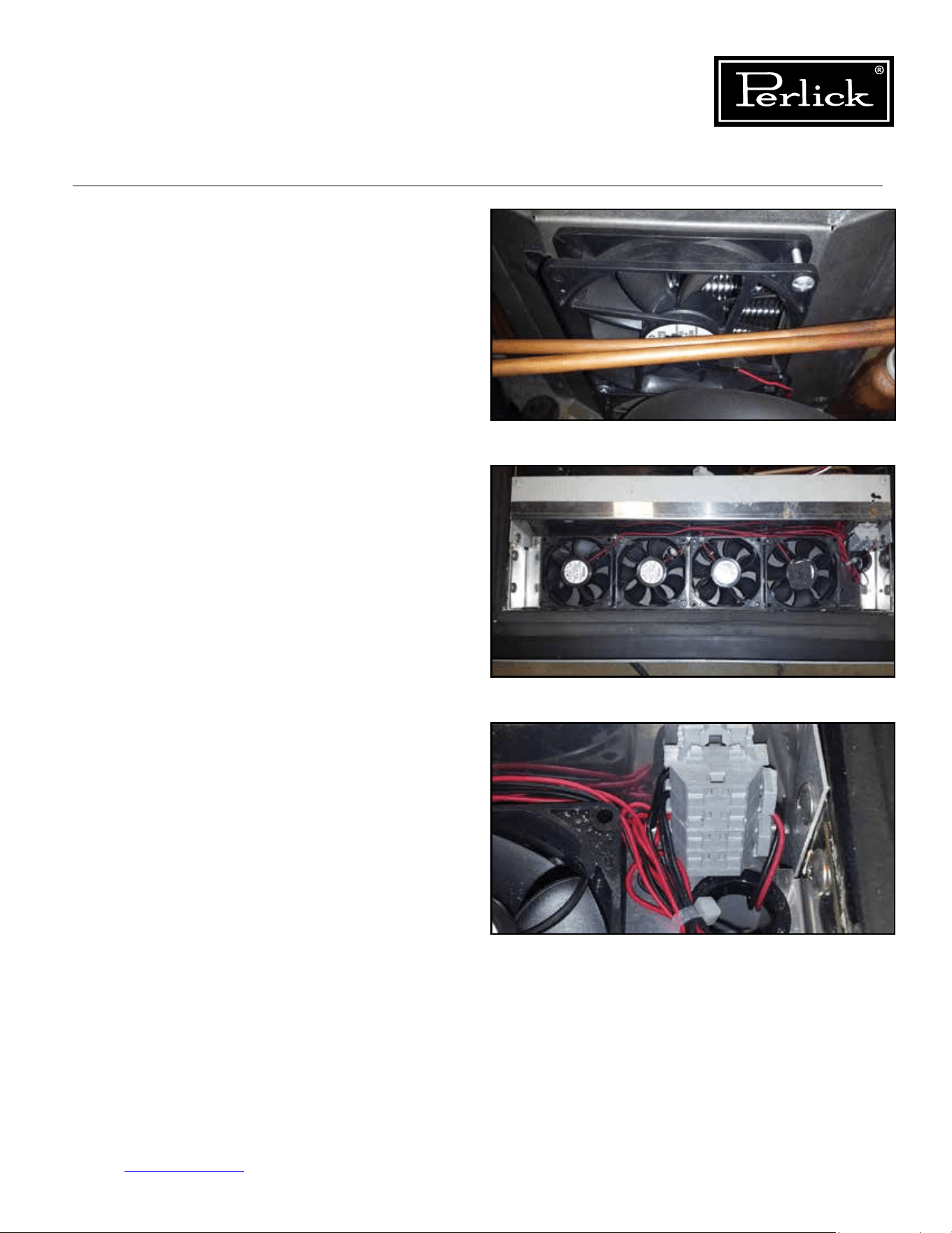
Column Refrigeration Service Manual
Return to Table of Contents
53
6.7 Replace Condenser Fan Motor
Following the instructions for replacing the
refrigeration module, remove the module from
the cabinet. Using a phillips screwdriver, remove
the fasteners holding the condenser fan motor to
the condenser shroud. Unplug fan from electrical
connection. Install new fan in reverse manor. Re-
install refrigeration module (replace module gasket
if worn or damaged).
See Figure 6-13.
6.8 Replace Evaporator Fan Motor
Following the instructions for replacing the
refrigeration module, remove the module from the
cabinet. Using a phillips screwdriver, remove the
fasteners holding the evaporator fan motor to the
fanhousing.Usingsmallatbladescrewdriver
disconnect fan leads from terminal block. Install
new fan in reverse manor. Re-install refrigeration
module (replace module gasket if worn or
damaged).
See Figure 6-14.1 and 6-14.2.
Figure 6-13. Condenser Fan Motor/Fastener
Figure 6-14.1. Evaporator Fan Motor/Fastener
Figure 6-14.2. Evaporator Terminal Block
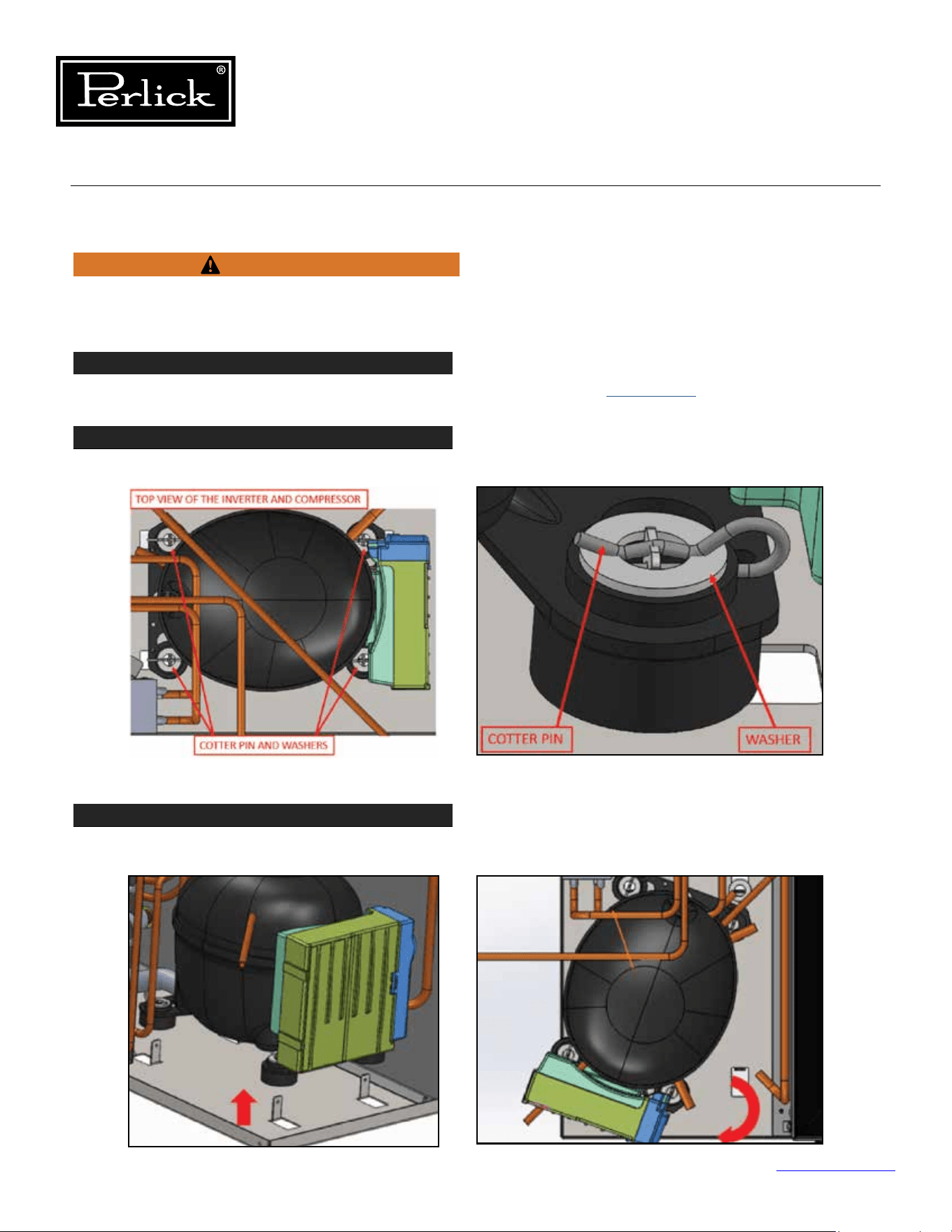
Column Refrigeration Service Manual
Return to Table of Contents
54
STEP 1
Remove Refrigeration Module from cabinet by following instructions in
Section 6.6.
STEP 2
Remove the four retaining cotter pins and washers from the tabs that secure the compressor to the base.
STEP 3
Carefully lift the compressor up so the rubber feet clear the tabs and rotate the compressor slightly to
access the inverter mounting screw.
6.9 Replace Inverter
Disconnect power to the unit before working on
product to avoid electrocution hazard.
Figure 6-15.1. Remove Cotter Pins
Figure 6-15.2. Lift And Rotate Compressor
WARNING
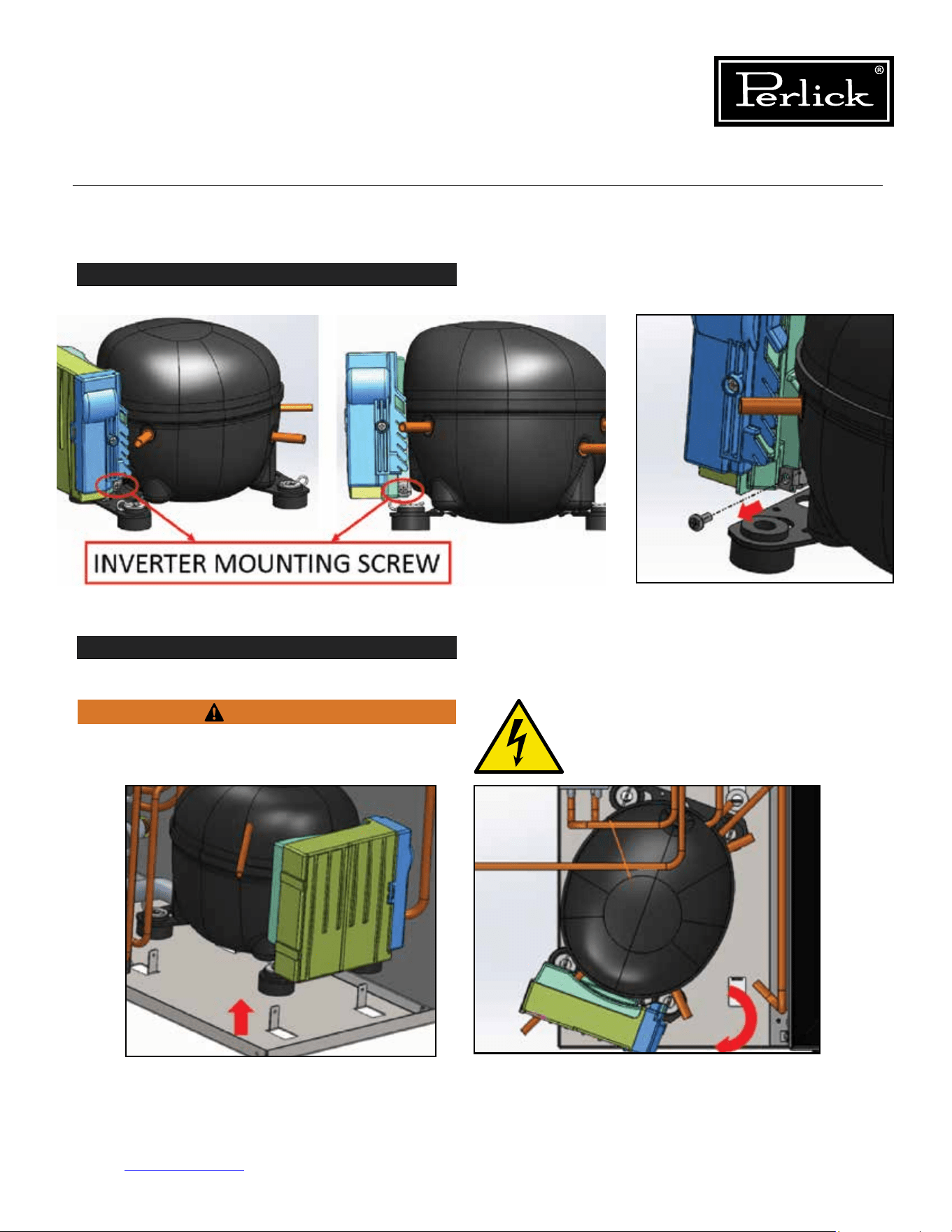
Column Refrigeration Service Manual
Return to Table of Contents
55
6.9 Replace Inverter (cont.)
STEP 4
Remove the inverter mounting screw and disconnect the inverter electrical connections.
STEP 5
Lift the inverter and pull away from compressor.
Before proceeding, ensure power has been
disconnected.
Figure 6-15.3. Inverter Mounting Screw/Electrical Connections
WARNING
Figure 6-15.4. Lift Inverter
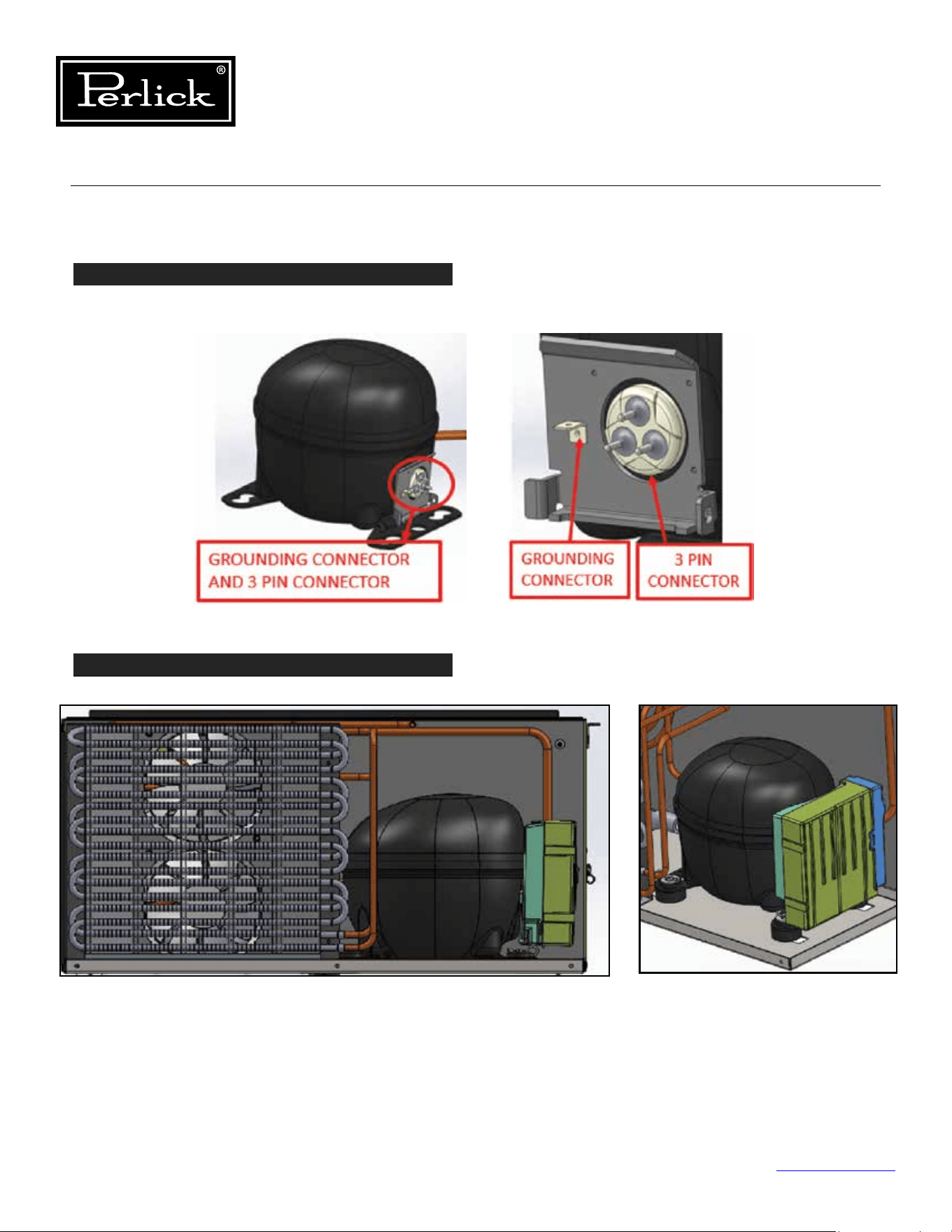
Column Refrigeration Service Manual
Return to Table of Contents
56
6.9 Replace Inverter (cont.)
STEP 6
Removethethree-pinconnectorandgroundconnectorfromthecompressorusingasmallathead
screwdriver.
STEP 7
Install the new inverter and remount the compressor.
Figure 6-15.5. Remove 3-Pin And Ground Connectors
Figure 6-15.6. Install Inverter And Remount Compressor
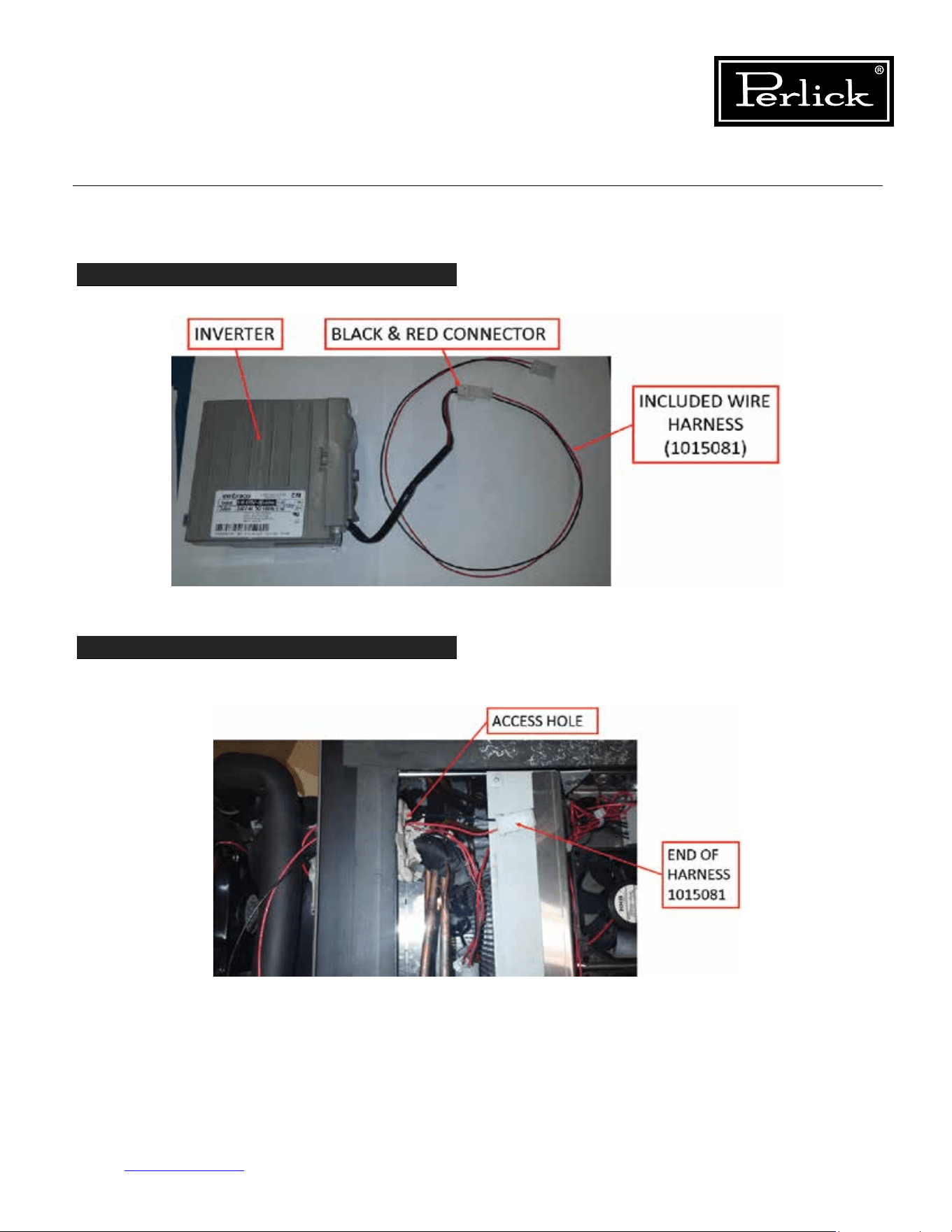
Column Refrigeration Service Manual
Return to Table of Contents
57
6.9 Replace Inverter (cont.)
STEP 8
Usingincludedwireharness1015081,connecttoblackandredconnectorcomingoinverter.
STEP 9
Feed other end of harness 1015081 through tube/wire access hole. (Single red lead is no longer required,
remove or wire tie so it is out of the way).
Figure 6-15.7. Connect Inverter Wires
Figure 6-15.8. Feed Harness End Through Access Hole
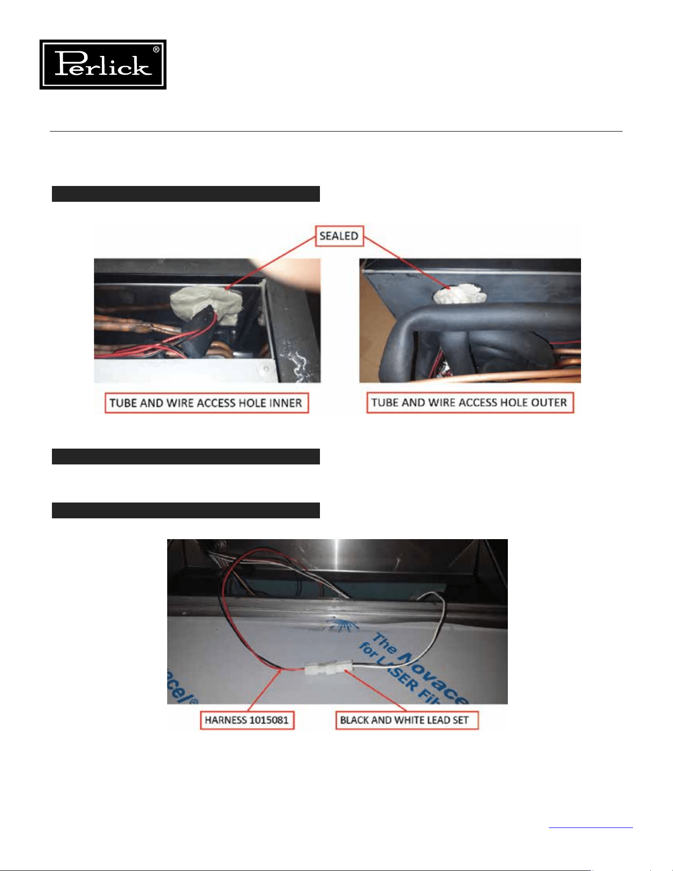
Column Refrigeration Service Manual
Return to Table of Contents
58
6.9 Replace Inverter (cont.)
STEP 10
Make sure the tube/wire access hole is fully sealed to prevent air leaks.
STEP 11
Install refrigeration module following instruction 6.6.
STEP 12
New harness 1015081 gets connected to spare black/wire lead set from cabinet.
Note: Inverter signal leads are connected to control board connection P4 for the frequency converter.
Figure 6-15.9. Seal Access Hole
Figure 6-15.10. Connect New Harness
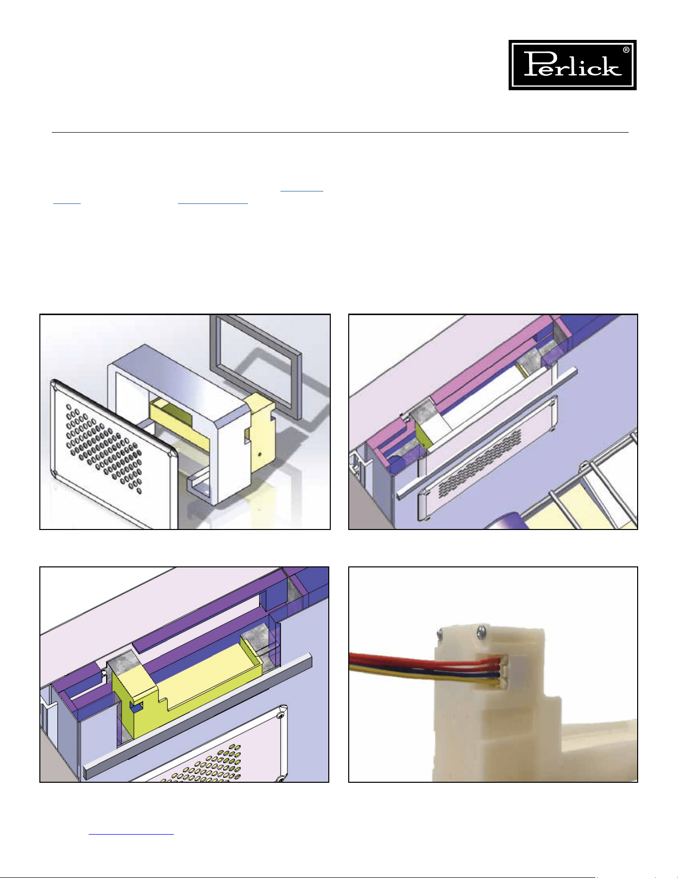
Column Refrigeration Service Manual
Return to Table of Contents
59
6.10 Replace Damper
To replace a damper, remove drawer (
see Section
8.14.
) or shelving (
see Section 8.16.
), to access the
damper. Remove the four damper cover mounting
fasteners. Pull out on the cover to remove the
damper assembly. Unplug the damper from the
wire harness. Replace the damper assembly. Plug
in damper, install damper assembly into opening
and fasten. Reinstalled drawers or shelves.
Figure 6-16.1. Refrigerator and Dual Zone
Wine Lower Damper
Figure 6-16.2. Dual Zone Wine Upper Damper
Figure 6-16.3. Dual Zone Wine Upper Damper
(Cover and Insulation Pad Suppressed)
Figure 6-16.3. Damper Electrical Connection

Column Refrigeration Service Manual
Return to Table of Contents
60
6.11 Leak Detection
IF A LEAK IS SUSPECTED, VENTILATE THE
AREA AND ENSURE THERE ARE NO NEARBY
IGNITION SOURCES.
Isobutane (R-600a) is a low pressure refrigerant
(30 PSIG @ 70°F). If checking for a leak, the
system should be at a minimum temperature of
70°F.
Use an isobutane (R-600a) compatible electronic
leak detector, check all joints, tubing and coils
for leaks. If a leak is detected, replace the
refrigeration module (
see Section 6.6
).
WARNING
DANGER
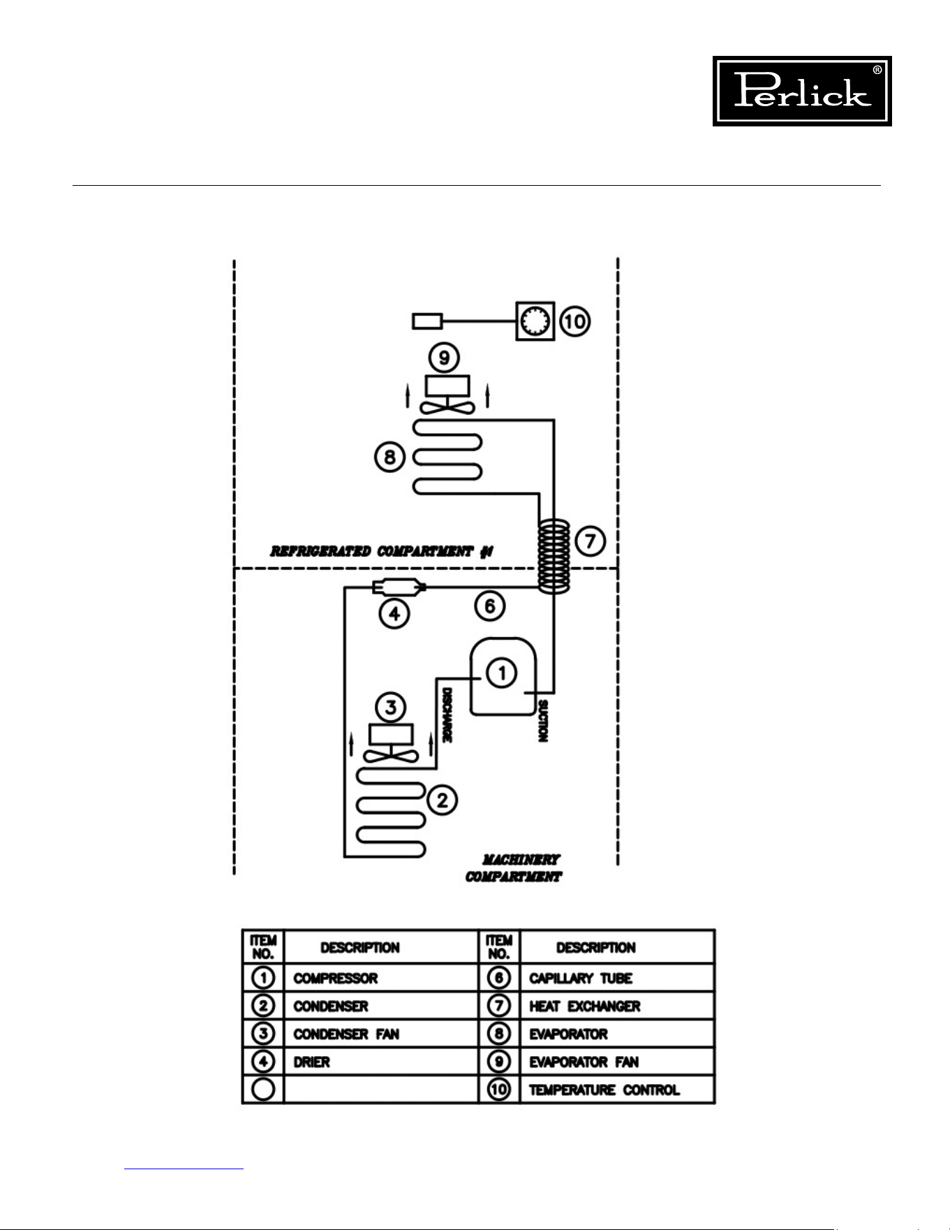
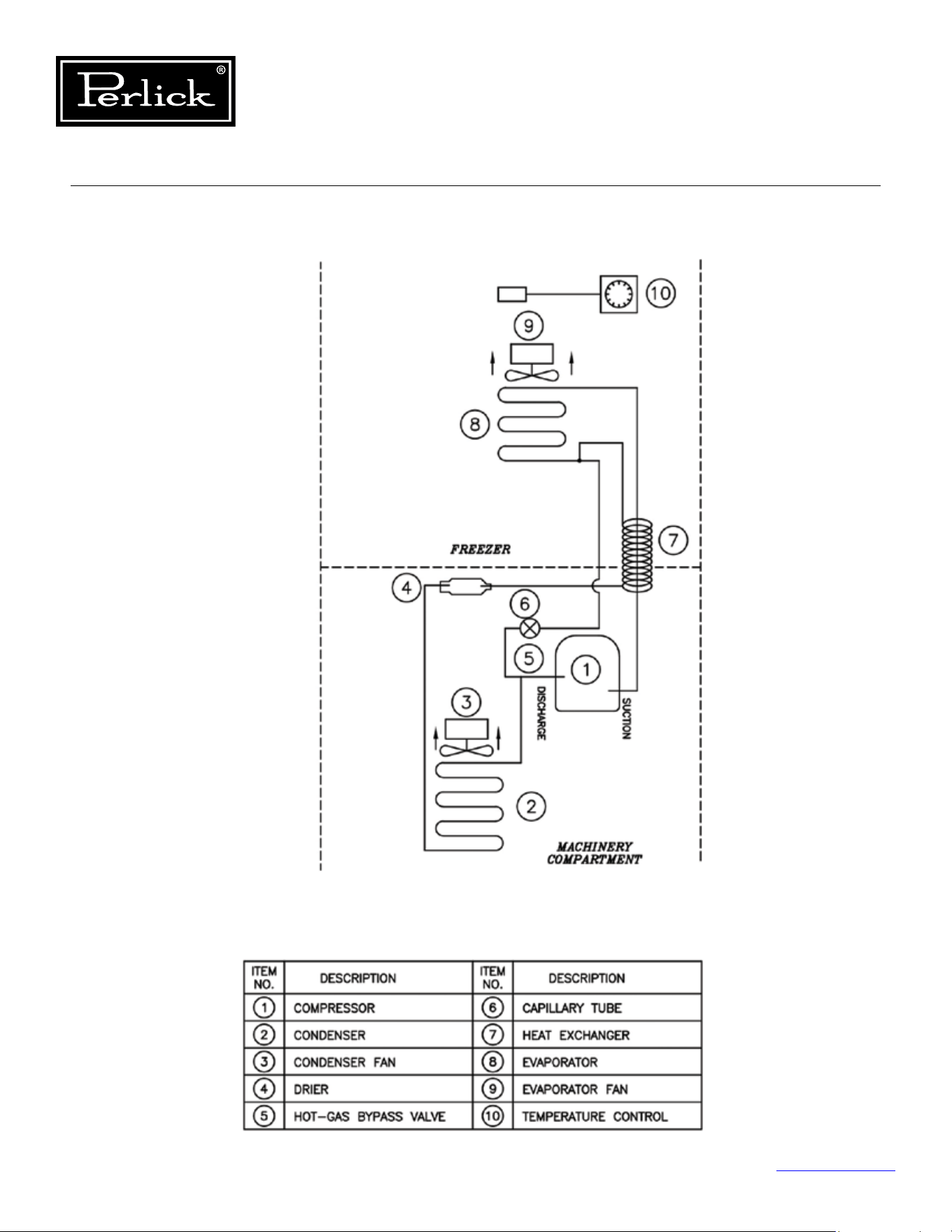
LED1: TheHeartbeatLEDashesredtoindicate
that the fuse F1 is closed, the electronics is
receiving power, and the software is running
normally.
LED2: When the green compressor LED is ON, it
indicates that the microprocessor is calling for
the relay to turn ON the compressor.
LED3: When the green defrost solenoid LED is ON, it
indicates that the microprocessor is calling for
the defrost solenoid to turn ON.
LED4: When the green condenser fan LED is ON, it
indicates that the microprocessor is calling for
the condenser fan to turn ON.
LED5: When this green LED is ON, it indicates that
the microprocessor is calling for the BLUE
interior lighting to turn ON.
LED6: When this green LED is ON, it indicates that
the microprocessor is calling for the white
interior lighting to turn ON.
LED7: When the green evaporator fan LED is ON, it
indicates that the microprocessor is calling for
the evaporator fan to turn ON.
Table 7.1. LED Diagnostics
The red heart beat
LED is not ashing
Conrmthat120VACisbeing
applied to the control board.
Remove the P1 plug and mea-
sure the resistance across F1. It
should be 0 ohm. Replace the
control if P1 is open.
Table 7.2. LED Troubleshooting
Column Refrigeration Service Manual
Return to Table of Contents
63
7.0 Component Operation
7.1 Control
The column products come with a custom designed
control, located in on the interior ceiling of the
product.
7.1.1 Diagnostics
See Figure 7-1.
for the control board’s integral
Load LED’s for diagnostic purposes. The LED’s
indicate which loads are in operation.
7.1.2 Troubleshooting
To determine if the control board is operating,
checkfortheheartbeatLED,itshouldbeashing.
Check all wire connections to ensure they are
connected without any type of damage If not
ashing,usingamultimetercheckforpowerat
connector P1, if no power, trace back to determine
where power is being interrupted. If power is
present, but no heartbeat, integral fuse is probably
open (check fuse for continuity), if open replace
board. To troubleshoot individual components,
check diagnostic LED’s for operation and then
conrmpowerisavailableatthecorresponding
pins. If the correct power is not available at any of
the pins, with the corresponding LED illuminated,
replace the board.
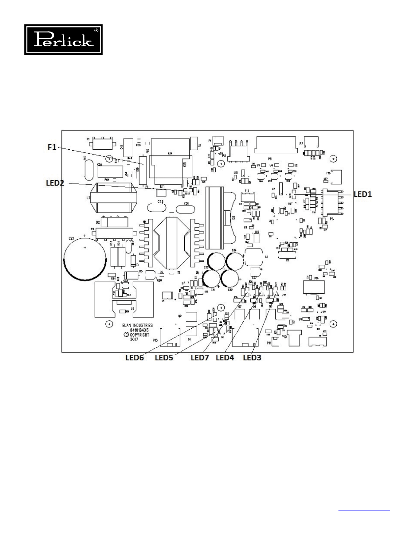

Column Refrigeration Service Manual
Return to Table of Contents
65
7.1.4 Replacing
To replace the control board:
1. Remove any shelving or product that will
interfere with accessing the inner ceiling of the
cabinet.
2. Once the inner ceiling is accessible, lower the
carbonlterhousingbypullingonthefront
edge to release the latch and mate connector
andremovethecarbonlter.
3. Remove the wire channel cover in the left rear
corner by removing the fasteners holding it in
place.
4. Next remove the two (2) fasteners located
ontherearangeofthecover,thatholdthe
control cover panel to the ceiling. For the
freezer and wine models slide the cover back
a ½” to disengage the tabs that mate with the
user interface bracket. For the refrigerator, pull
forward on the cover to disengage the open
hemangeonthefrontofthecover.
5. Slowly lower the cover and remove the bushing
that protects the wires going through the wire
access hole.
6. Remove the wires through the key slot hole
and set the cover panel aside. The control
board is now visible. (If desired for the freezer
and wine models, the user interface can be
removed). (
See Section 7.2.
).
7. Disconnect all wire harnesses from the control
board, noting connecting locations if required.
8. Remove the 4 fasteners that hold the control
board to the ceiling (support the control
board).
9. Replace with new control board, installing in
reverse steps.
10. Ensure all electrical connections are correct and
properly engaged.
7.2 User Interface
If user interface is not operational, check electrical
connections from the control board to the user
interface. Use Control Replacing (
see section
7.1.4.
) instructions to access the control board and
user interface connections. For a refrigerator, there
is a third connection located at the rear of the
user interface housing, to access, remove the deli
bin glass lid by removing the two pivot fasteners,
one on each end of the lid, then pull the two pins
on the edges of the user interface housing and
pull out on the housing. If connections are good,
replace the user interface assembly.
Replacing
Freezer and Wine
See Control Replacing instructions (
see section
7.1.4.
). Once the control board is accessible,
remove the two fasteners, one on each inner
end of the user interface bracket. Slide the user
interfaceassemblyforwardtoreleasetheangeon
the front top. Once loose, disconnect the harness.
Replace following reverse instructions.
Refrigerator
The user interface housing is the complete sheet
metal housing that contains the user interface. To
remove the housing, remove the deli bin glass lid
by removing the two (2) pivot fasteners, one on
each end. Next, pull the two retaining pins from
the left and right edge of user interface housing.
Finally, pull out the housing, it will slide along the
rails, manage the wire harness and disconnect
before pulling completely out of the rails. Early
models may require removal of the left rear wall
cover panel to access the third connector. To
remove that panel, remove all shelving, remove
thecenterandleftpilasterandnallyremove
the panel. Locate the connector and disconnect.
Replace with a new user interface assembly
and complete user interface wire harness so the
connection is at the rear of the housing.
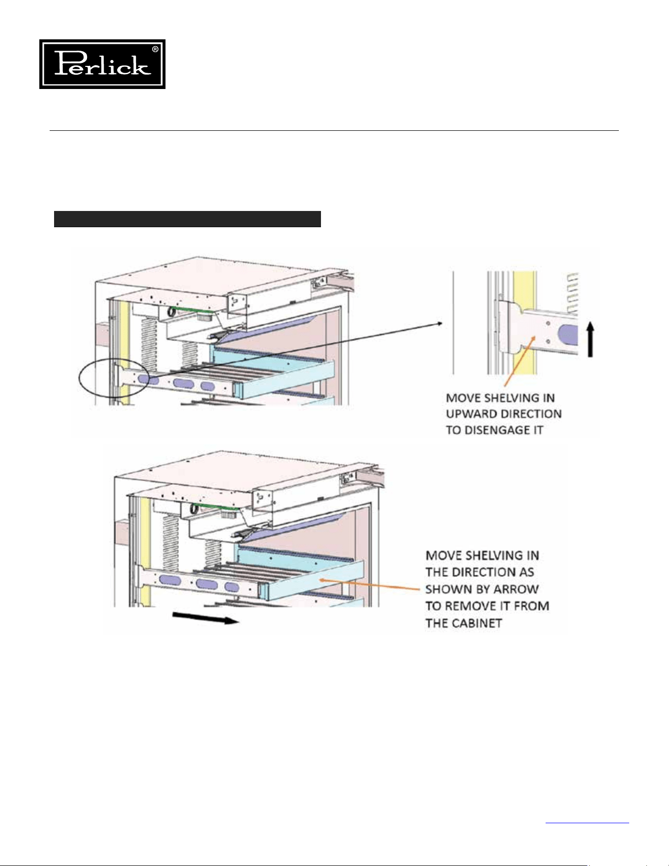
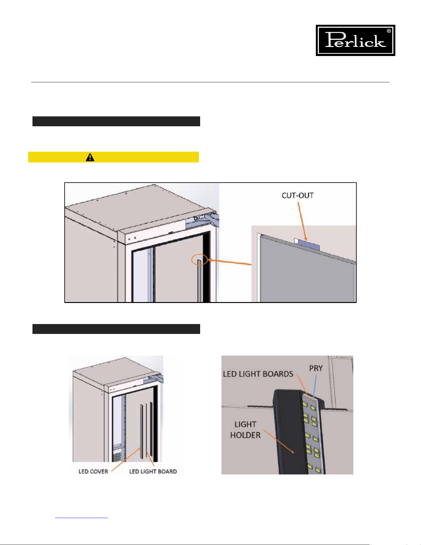
Column Refrigeration Service Manual
Return to Table of Contents
67
7.3.1 Replace Wine Lighting (cont.)
STEP 2
Usingsmallatscrewdriverpryoutlightcoveringeachledlightboardoncabinetsidewalls(Uppercovers
have a cut-out at the top of each opening, lower covers have cut-out at the bottom of each opening).
STEP 3
Lightboardsareadhesivebacked,sousingaatbladescrewdriver,startatoneendofboardandprythe
board of the light housing. Gradually work your way from one end to the other to remove completely.
Be careful while removing cover, do not scratch
liners.
CAUTION
Figure 7-2.2. Pry Light Covering
Figures 7-2.3. Pry Light Housing Board
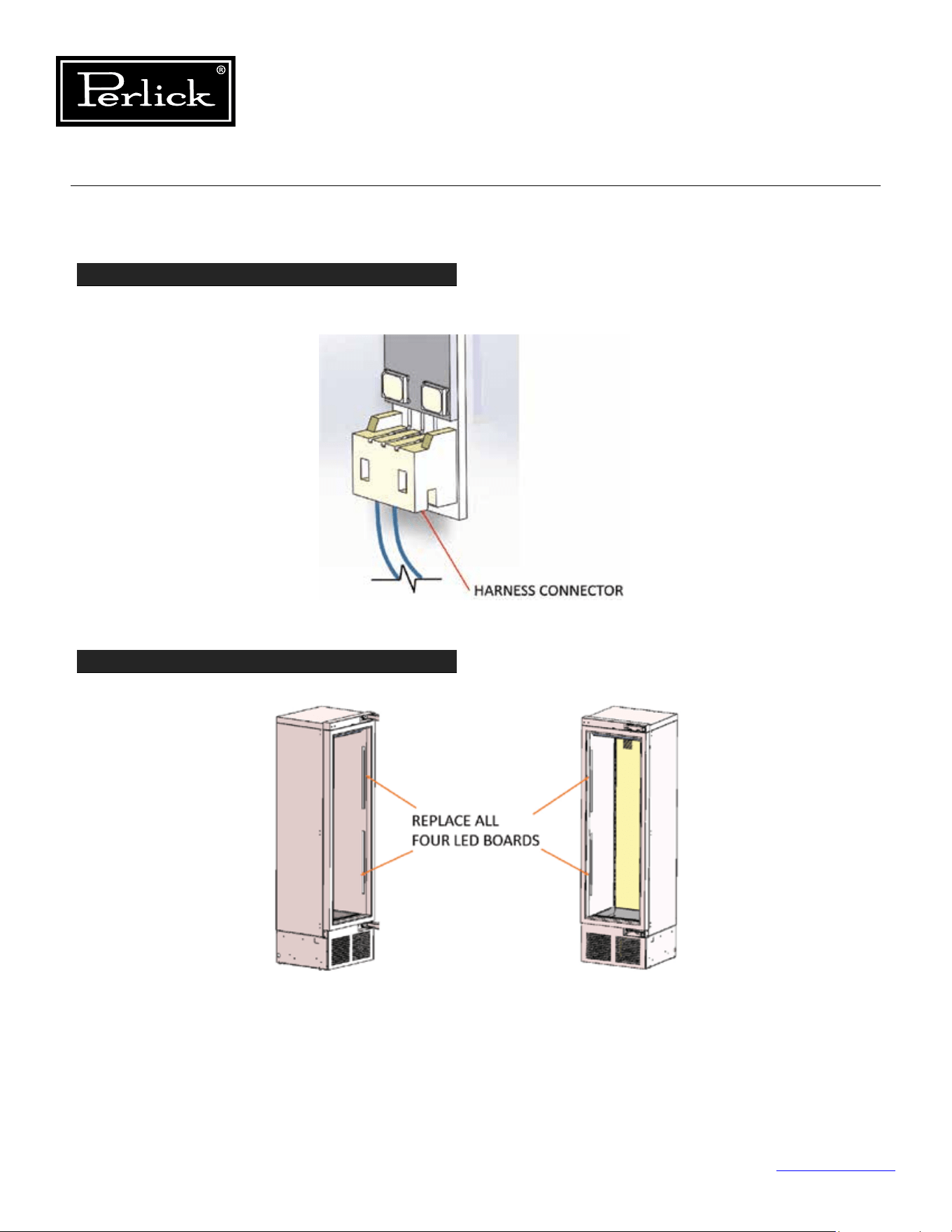
Column Refrigeration Service Manual
Return to Table of Contents
68
7.3.1 Replace Wine Lighting (cont.)
STEP 4
Disconnect board from harness using harness connector to remove (Do not pull on wires and cause
damage).
STEP 5
Replace led board with new and continue to replace all four (4).
Figure 7-2.4. Disconnect Board From Harness
Figure 7-2.5. Remove Wine Shelving
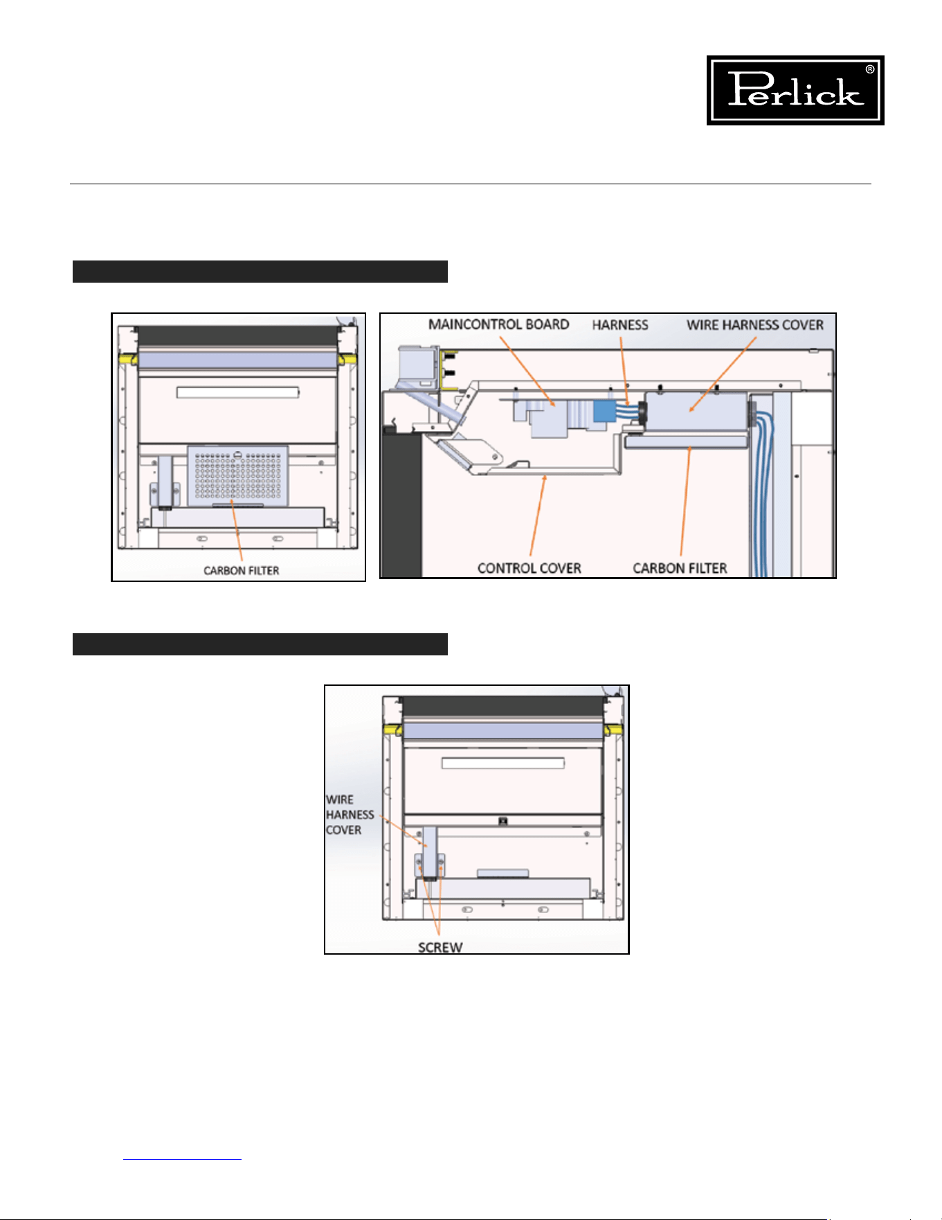
Column Refrigeration Service Manual
Return to Table of Contents
69
7.3.1 Replace Wine Lighting (cont.)
STEP 6
Removecarbonlterfromhousingattopofcabinet.
STEP 7
Remove wire harness cover by removing screws that hold it in place (Top rear left of cabinet).
Figures 7-2.6. Remove Carbon Filter
Figures 7-2.7. Remove Wire Harness Cover
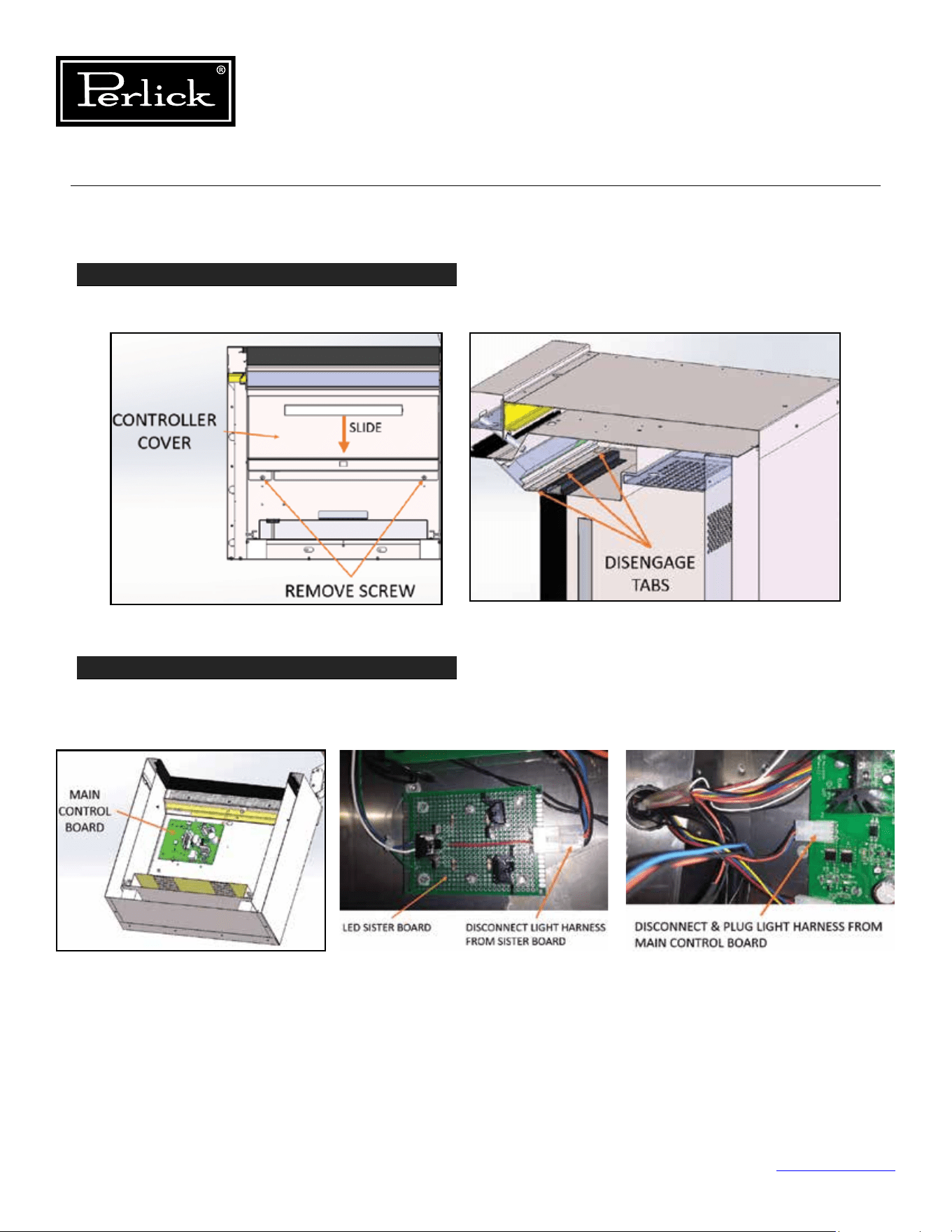
Column Refrigeration Service Manual
Return to Table of Contents
70
7.3.1 Replace Wine Lighting (cont.)
STEP 8
Removecontrollercoverbyremovingtwoscrewsfromrearangeofcover.Slidecovertowardsrearof
cabinet to disengage tabs on cover that mate with user interface housing.
STEP 9
Disconnect light harness from sister board adjacent to main control board and follow wires from sister
board to main control board and disconnect and plug light harness directly into main control board (Sister
board is no longer requirement with new led boards).
7.3.2 Replace Freezer and Refrigerator Lighting
The freezer and refrigerator lighting can be replaced similarly to the wine instructions, however, there is no
sister board for these two models. Additionally, each drawer contains a light in the ceiling divider panel.
Figures 7-2.8. Remove Controller Cover
Figures 7-2.9. Disconnect Light Harness
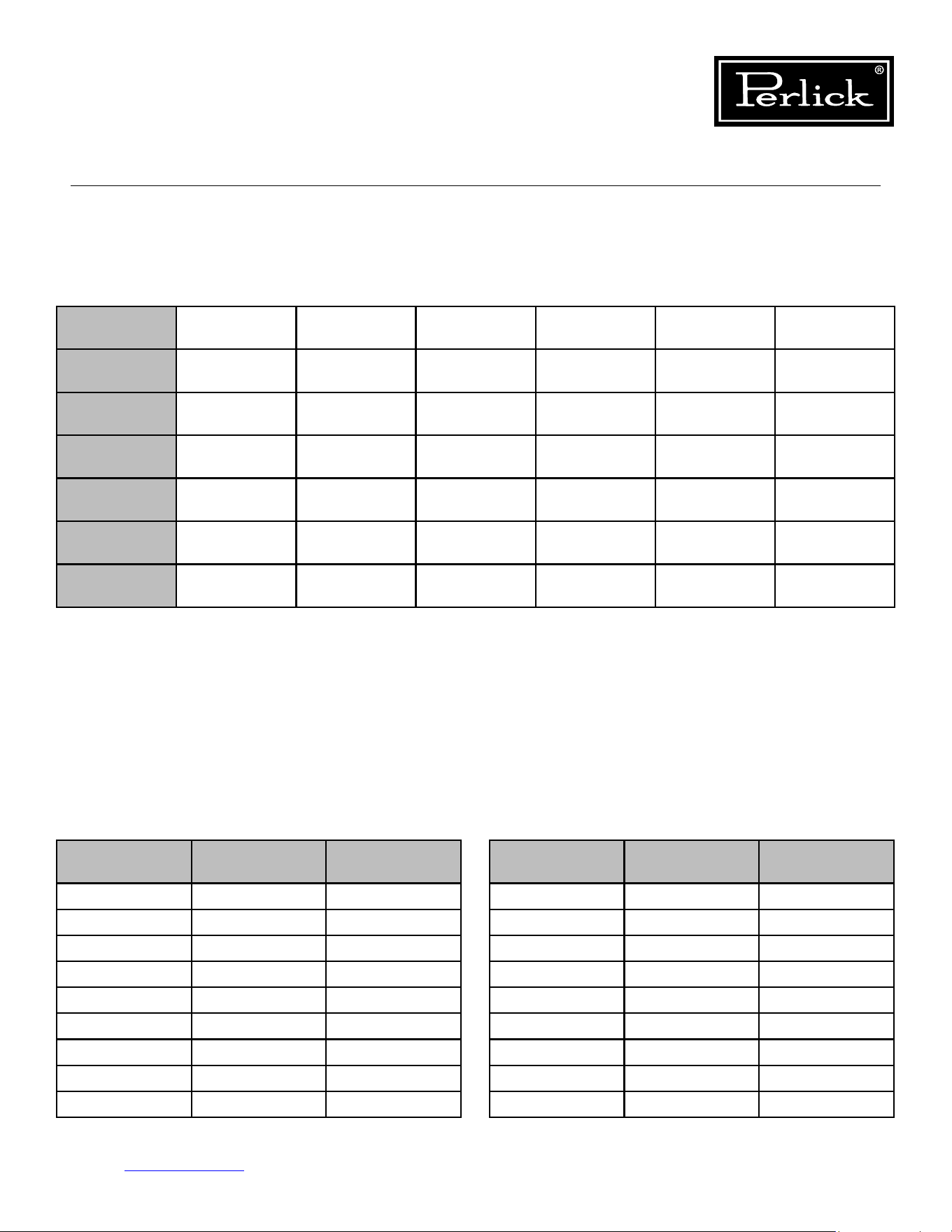
Model
Temperature
Sensor 1
Temperature
Sensor 2
Temperature
Sensor 3
Temperature
Sensor 4
Temperature
Sensor 5
Temperature
Sensor 6
NTC Thermistor NTC Thermistor NTC Thermistor NTC Thermistor
Temp/Humidity
Sensor
Temp/Humidity
Sensor
Refrigerator
Main
Compartment
Deli Drawer Meat Drawer Evap Temp
Produce
Drawer
Freezer
Main
Compartment
Evap Temp
Single-Zone
Wine
Evap Temp
Main
Compartment
Dual-Zone
Wine
Evap Temp
Lower
Compartment
Upper
Compartment
Associated
Alarms
P1, L1, H1 P2, L2, H2 P3, L3, H3 P4, L4, H4 P5, L5, H5, R5 P6, L6, H6, R6
**NOTE: Alarm will stop once the cause of the alarm is corrected.
P1, P2, P3, P4, P5, P6 = Open/Disconnected NTC Thermistor or Temperature/Humidity Sensor
L1, L2, L3, L4, L5, L6 = Low Temperature Alarm (Sensed temperature is below X degrees F below setpoint for over 30
minutes)
H1, H2, H3, H4, H5, H6 = High Temperature Alarm (Sensed temperature is above X degrees F above setpoint for over
30 minutes)
r5, r6 = Open/Disconnected Humidity Sensor
d1 = door open alarm
Troubleshooting - To troubleshoot, check all connections and using a multimeter check resistance values.
Temperature
(°C)
Temperature
(°F)
Resistance
(OHMS)
Temperature
(°C)
Temperature
(°F)
Resistance
(OHMS)
-30 -22 111300 15 59 14690
-25 -13 86430 20 68 12090
-20 -4 67770 25 77 10000
-15 5 53410 30 86 8313
-10 14 24270 35 95 6940
-5 23 33900 40 104 5827
0 32 27280 45 113 4911
5 41 22050 50 122 4160
10 50 17960 55 131 3536
Table 7.3. Column Temperature/Humidity Sensors
Table 7.4. Temperature - Resistance Values
Column Refrigeration Service Manual
Return to Table of Contents
71
7.4 Temperature Probes
Below is a table showing the type of probe used for sensing temperatures for each model. The probe is a
10K ohm NTC probe. See resistance values below.
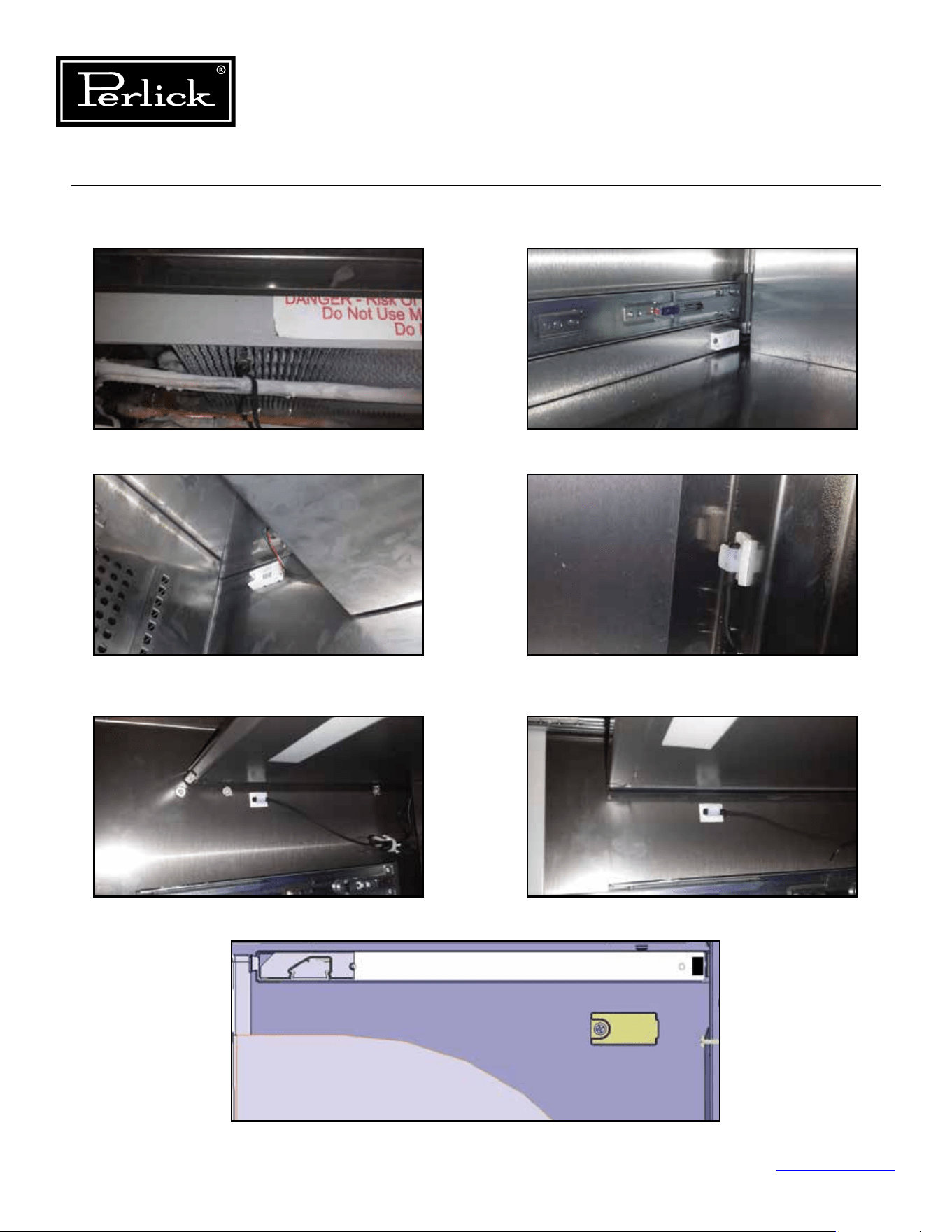
Column Refrigeration Service Manual
Return to Table of Contents
72
7.4.1 Probe Locations
Figure 7-3.1. Evaporator Temperature Probe
Figure 7-3.3. Dual-Zone Wine
Upper Compartment and Single-Zone Wine
Temperature/Humidity Sensor
Figure 7-3.5. Refrigerator
Deli Bin Temperature Probe
Figure 7-3.2. Dual-Zone Wine
Lower Compartment Temperature/Humidity Sensor
Figure 7-3.4. Freezer and Refrigerator
(Main Compartment) Temperature Probe
Figure 7-3.6. Refrigerator
Meat/Fish Bin Temperature Probe
Figure 7-3.7. Refrigerator
Tip-Out Bin Temp/Humidity Sensor
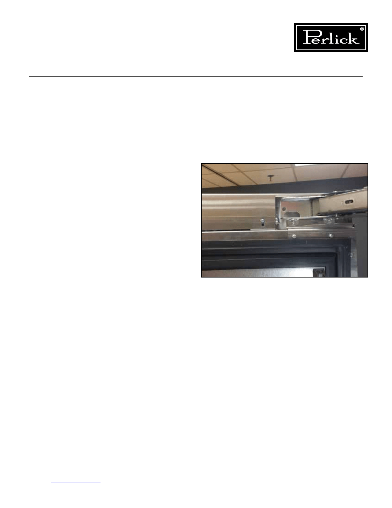
Column Refrigeration Service Manual
Return to Table of Contents
73
7.4.2 Troubleshooting
Ensure all connections are good and there is no
damage to the wires. Check resistance values
based on temperature, ensure that the probe is at
a stabilized temperature.
For the temperature and humidity sensors used
on the wine units and the tip-out bin of the
refrigerator, these are electronic devices. Ensure
that all connections are made. The dual zone wine
reserves have two separate sensors, one for each
compartment.Thedierencebetweenthetwoisa
dierentinternaladdress.Ensurewhichsensoris
being replaced as the sensors can’t have the same
address as this will confuse the control board and
it will not know which sensor it is talking with.
7.5 Door Switch
The door switch is a simple reed switch, located
at the top of the cabinet. The actuation magnet
should be located in the cutout on the door top
trim cover. Of the two mounting locations for
the magnet, it should always be located at the
mounting location furthest from the hinge.
See
gure7-4.
7.5.1 Troubleshooting
Using a multimeter, check continuity of the reed
switch and ensure it opens and closes through
proximity of the magnet.
Figure 7-4. Door Magnet (Reed Switch)
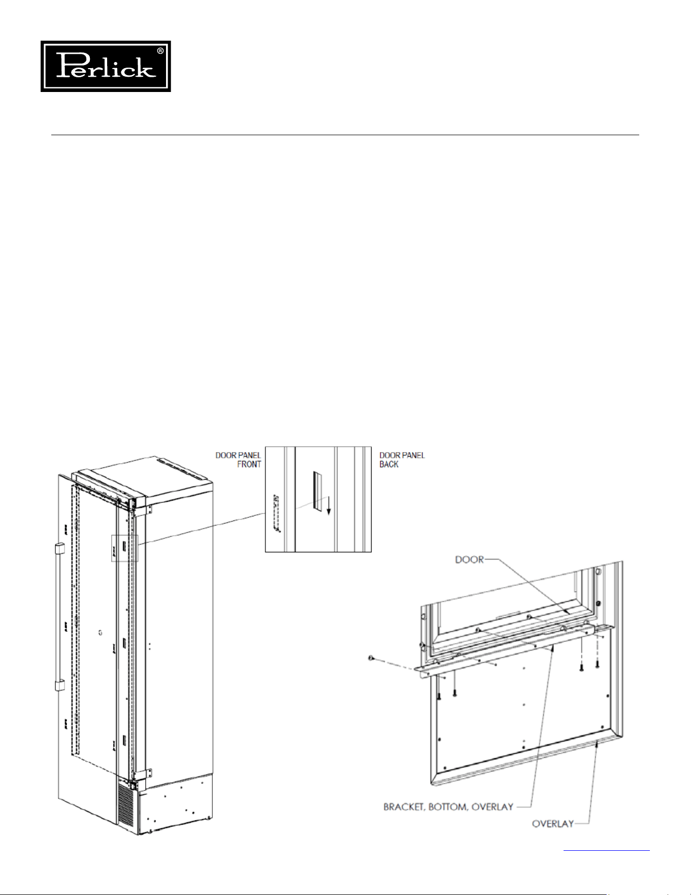
Column Refrigeration Service Manual
Return to Table of Contents
74
8.0 Doors, Drawers, Shelving and Misc.
8.1 Overlay Panel Installation
and Adjustments
Typical panel dimensions are based on 84”
(2134mm)nishedheightwith1/8”(3mm)
reveals. Template must be adjusted for panels
exceeding typical dimensions.
1. Place panel face down on a protected work
surface.
2. Attach six clips to the back of overlay in
locations indicated in wood overlay drawing
below.
3. Use provided #10 x 1/2” screws to attach clips
to overlay.
4. Overlay then slides onto door face.
5. Attach overlay to door adjustment brackets using
remaining #10 x 1/2” screws.
6. Once mounted, adjust overlay to match adjacent
cabinetry.
7. Close the door to make adjustments to align
panels and reveals.
8. For up and down adjustments, turn the height
adjustment screws in the top bracket (
see Top
of Door illustration, Figure 8-2, on page 75
) in
and out.
9. Adjust the screws as needed to achieve an even
reveal on each side of the door overlay.
10.Oncenaladjustmentsaremadetotheposition
of the door overlay, secure the overlay in place by
installing the bottom overlay brackets.
See Figure 8-1.
BOTTOM OF DOOR
Figure 8-1. Overlay Panel Installation
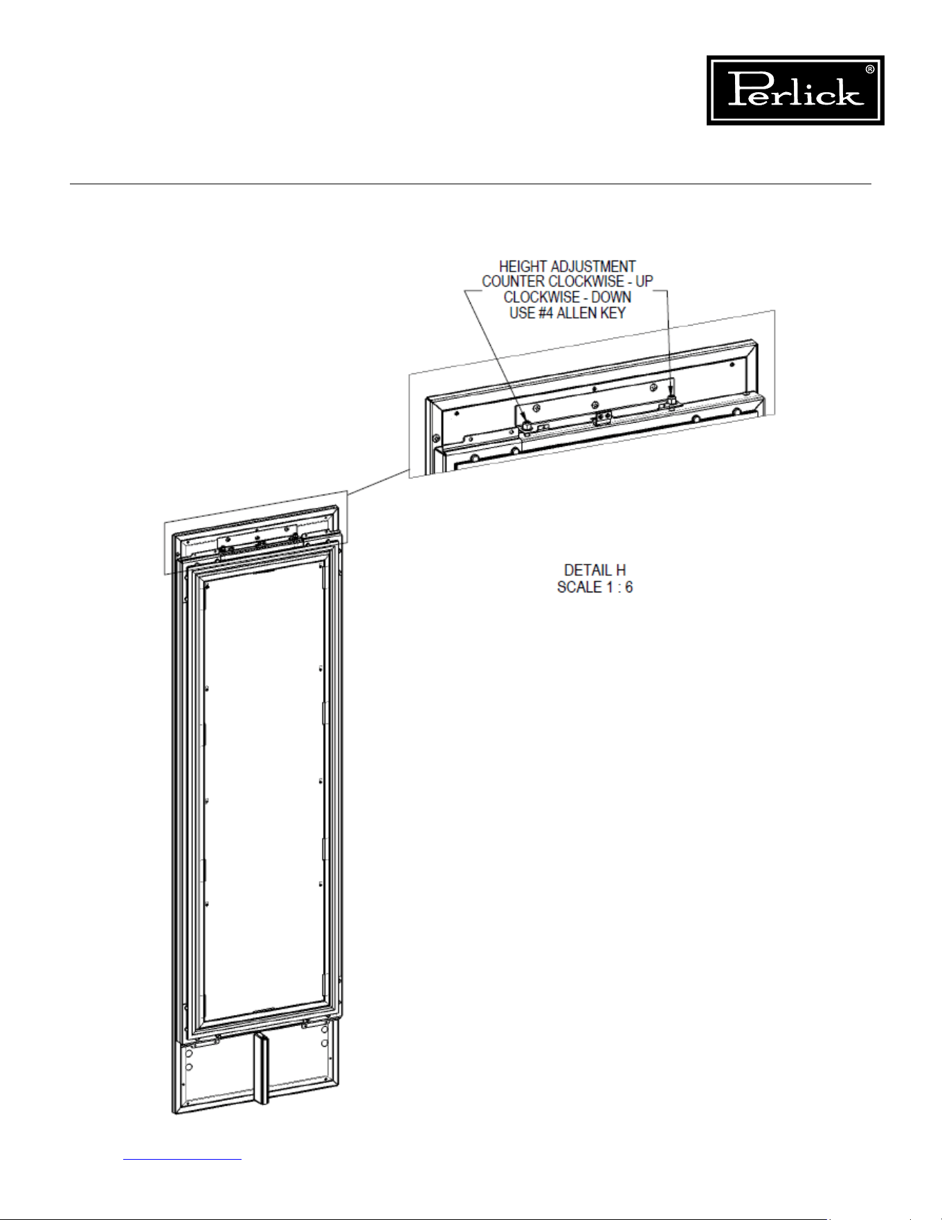
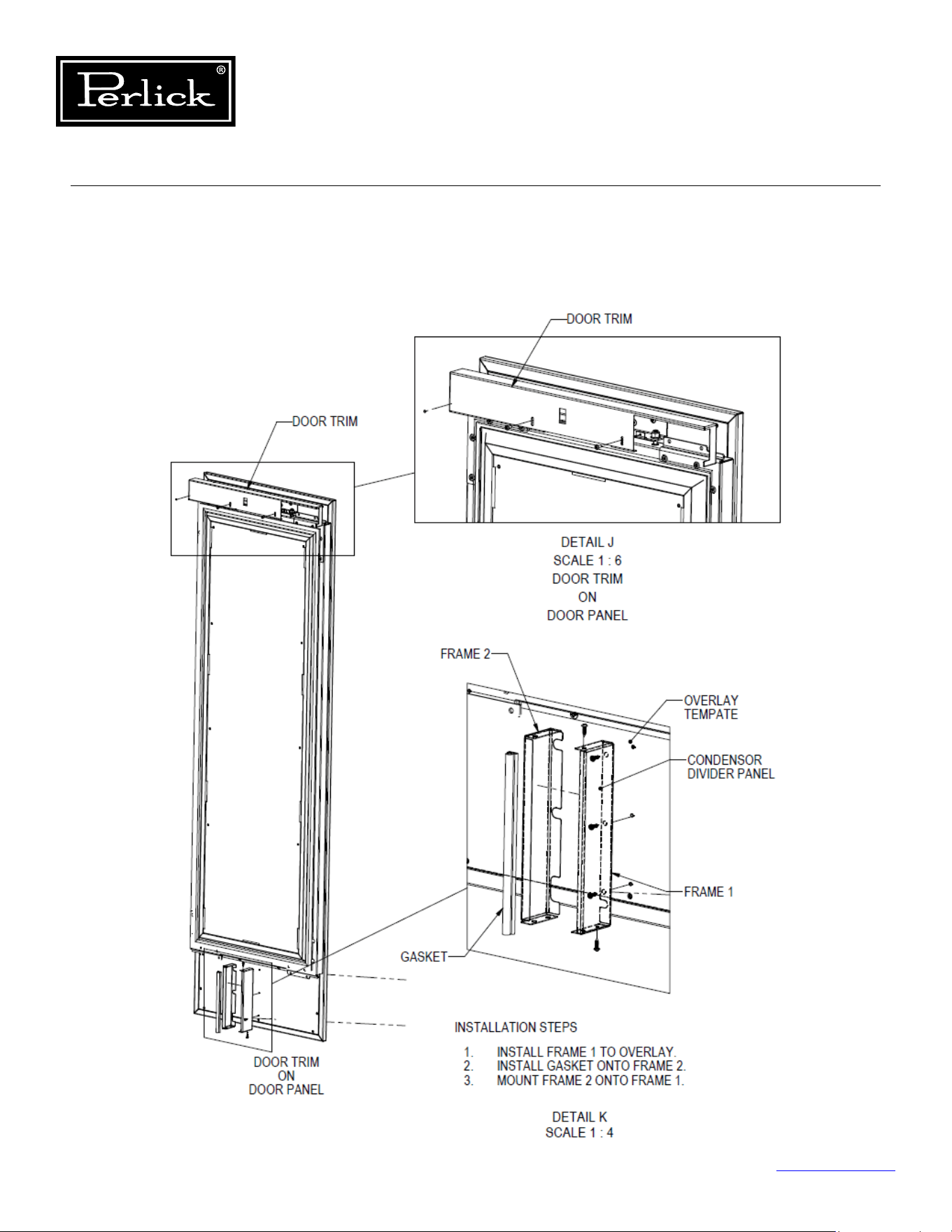
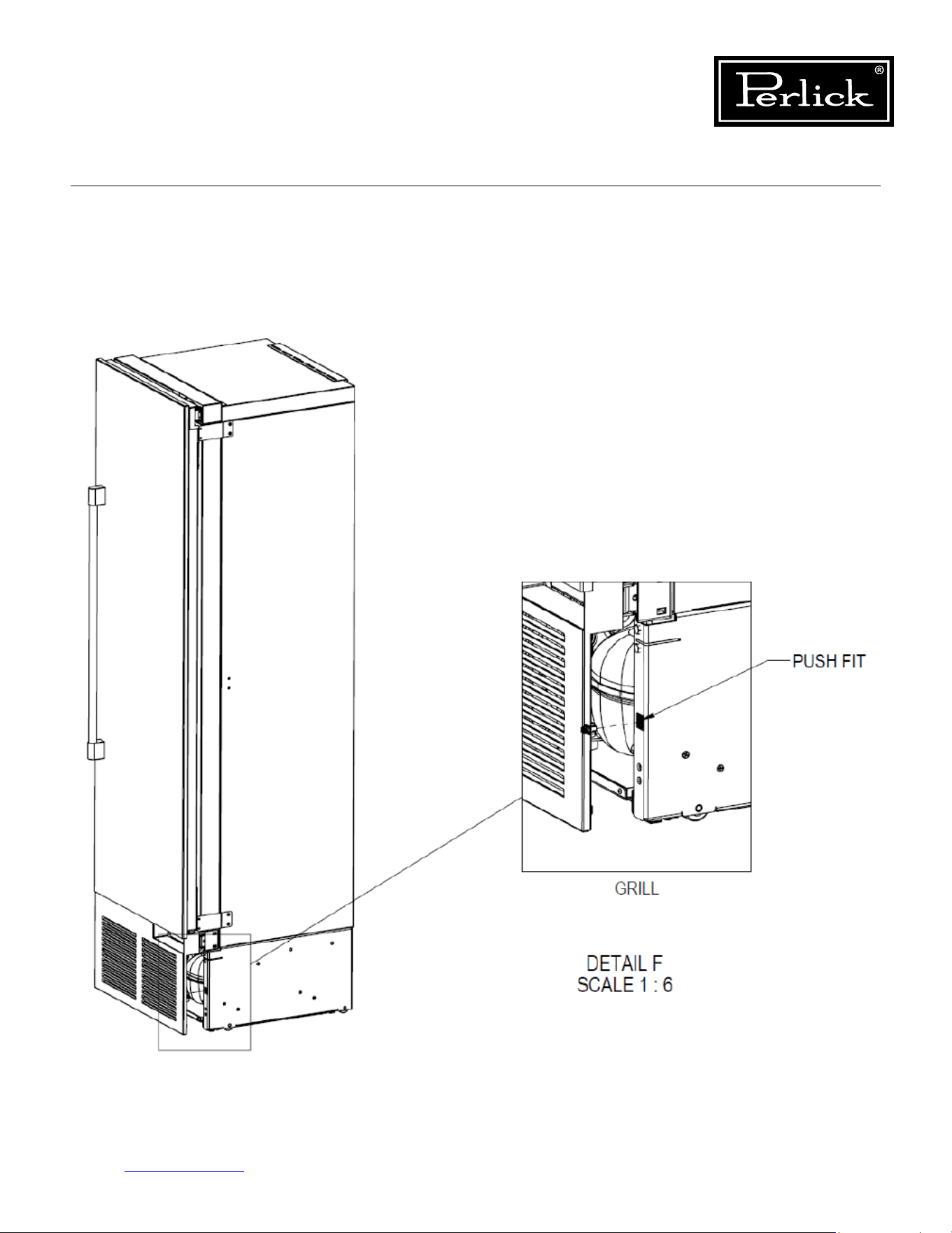
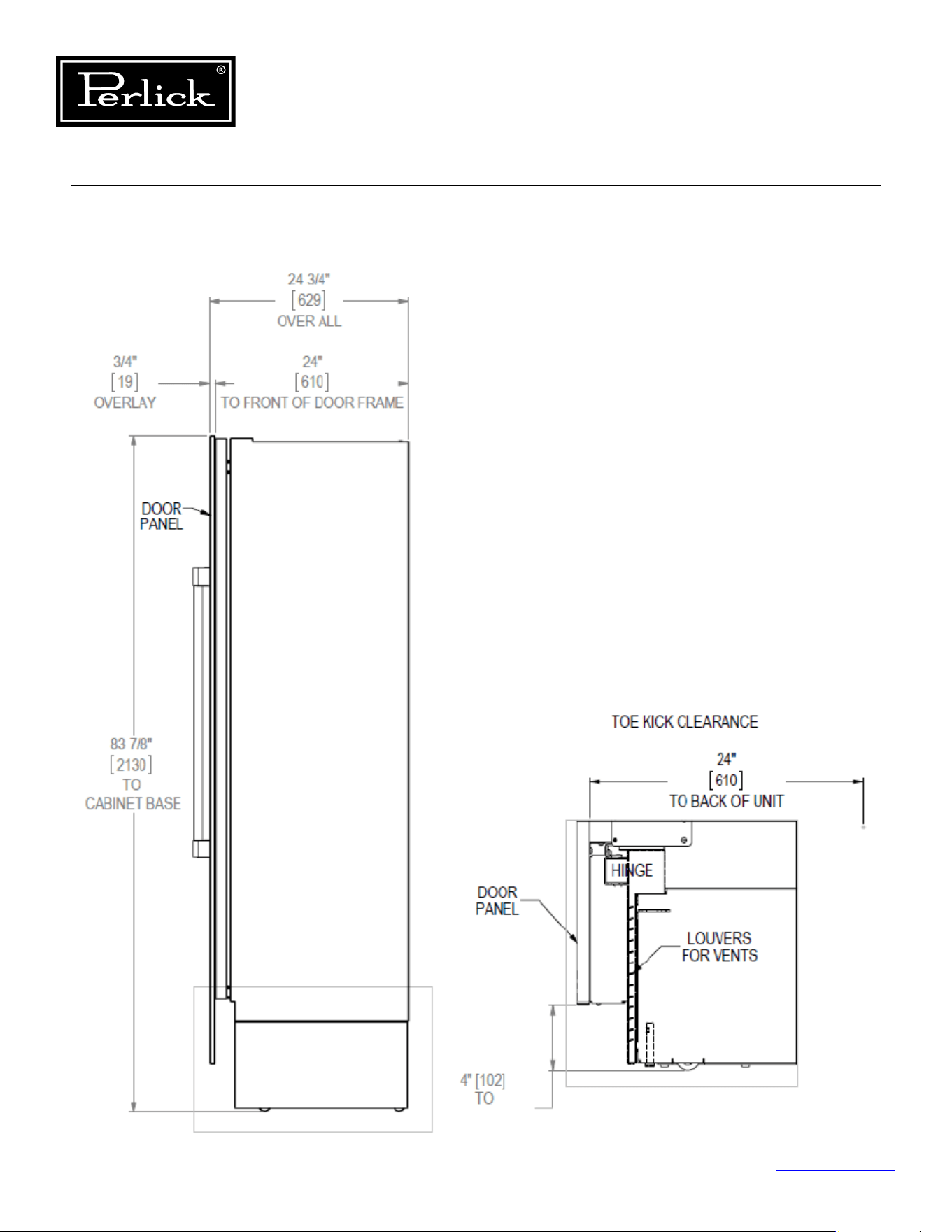
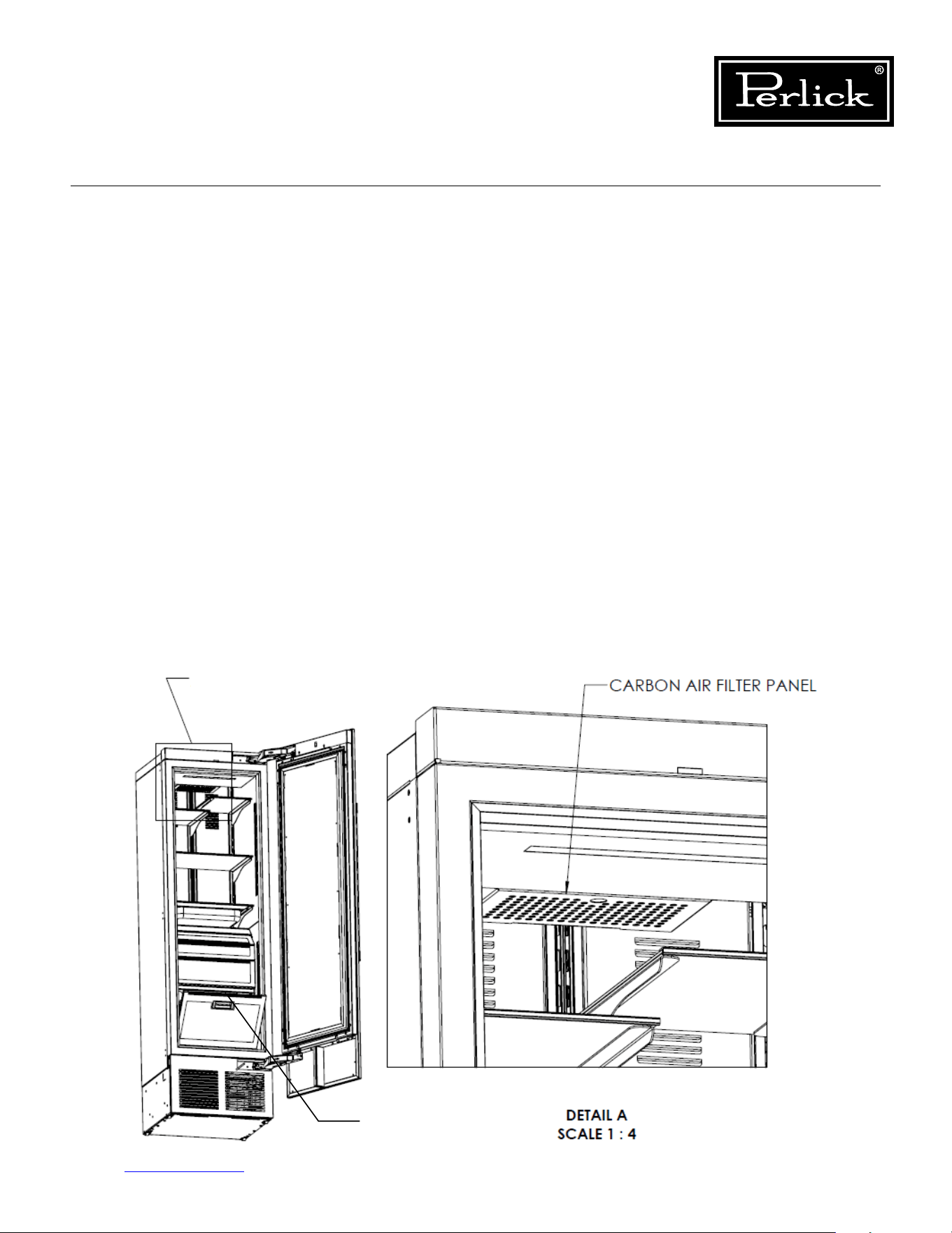
Column Refrigeration Service Manual
Return to Table of Contents
79
8.6 Installing Filters
8.6.1 Carbon Air Filters
Carbonairltersshouldbeplacedintheholderin
the perforated panel located in the top-rear of the
cabinet (A).
NOTE:Wheninstallingcarbonairlterinwine
units, the top rack will need to be removed to
access the perforated panel.
1. Removethelterfromtheplasticbagbefore
installing into the unit. Take care not to open or
puncture the tyvek bag in the casing.
2. Pullrmlytolowerthecarbonairlterpanel.
3. Placethecarbonairlterintotheholder
directly onto the panel and close panel - push
rmlytoengageclosureclips.
4. It is recommended to replace the carbon air
lterevery3-6months.
8.6.2 Ethylene Air Filters
Ethyleneltersshouldbeplacedintheholderin
top of the tip-out produce bin (B).
1. Removethelterfromtheplasticbagbefore
installing into the unit. Take care not to open or
puncture the tyvek bag in the casing.
2. Openthetip-outbintoaccesslterhousing
located on the top of the bin.
3. Slidelterintohousingandclosetip-outbin.
4. Itisrecommendedtoreplacetheethylenelter
every 3 months.
B
A
Figure 8-6. Air Filter Installation
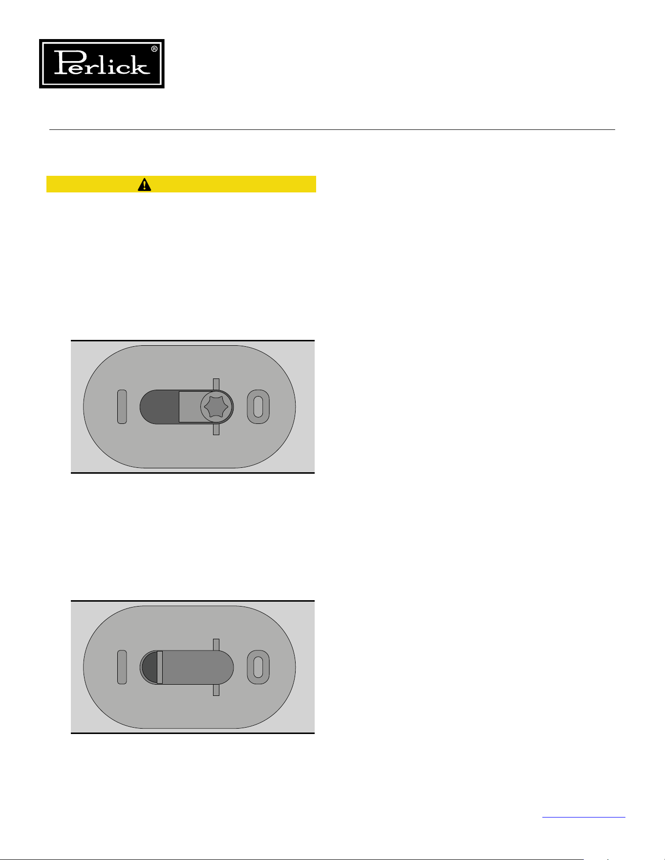
Column Refrigeration Service Manual
Return to Table of Contents
80
8.7 Activation/Deactivation of Hinges
Pinch hazard! Always de-activate hinges before
removing from door and cabinet.
To activate the self-closing feature of the hinge
follow these steps:
1) Open the door to expose the T-20 torx fastener
in the obround hole in the hinge labeled
position zero (0) and one (1).
2) Using a T-20 torx drive, turn the fastener
approximately 9 to 9-1/2 turns from the zero
(0) position to the one (1) position. Do not
over-tighten (2Nm torque max).
To de-activate the hinges move the T-20 torx
fastener from position one (1) to position zero
(0) by turning the fastener 9 to 9-1/2 turns
(seegures8-7.1and8-7.2foractivatedand
deactivated positions)
.
CAUTION
Figure 8-7.1. Hinge activation fastener
(shown in de-activated position).
Figure 8-7.2. Hinge activation fastener
(T-20) (shown fully activated).
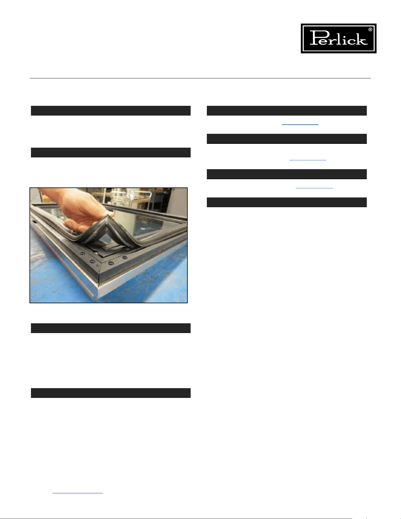
Column Refrigeration Service Manual
Return to Table of Contents
81
8.8 Replace Door Gasket
STEP 1
Door and drawer gaskets can be replaced without
removing the door or drawer from the cabinet.
Open the door or drawer.
STEP 2
Remove gasket by lifting at one corner and pulling
gasket away from door/drawer. Work around door/
drawer until gasket is free.
STEP 3
Toreplace,startatonecornerandpressrmlyto
seat the gasket dart in the channel of the door/
drawer frame. Feel for a click to indicate the dart is
completelyseated.Installallcornersrstandthen
work your way around the perimeter of the door/
drawer to seat the gasket into its track.
STEP 4
Finish by going around the gasket once more to
feelforanygapsandtoensurethegasketisat
and fully seated.
8.9 Replace Door
STEP 1
Deactivate Hinges
(see Section 8.7.).
STEP 2
RemoveDoorTrimCoverandcondenserairow
divider from Overlay
(see Section 8.1.).
STEP 3
Remove Overlay Panel
(see Section 8.1.).
STEP 4
Remove the fasteners holding the door to the
hinges.
Follow reverse instructions to install the new door.
Figure 8-8. Removing gasket.
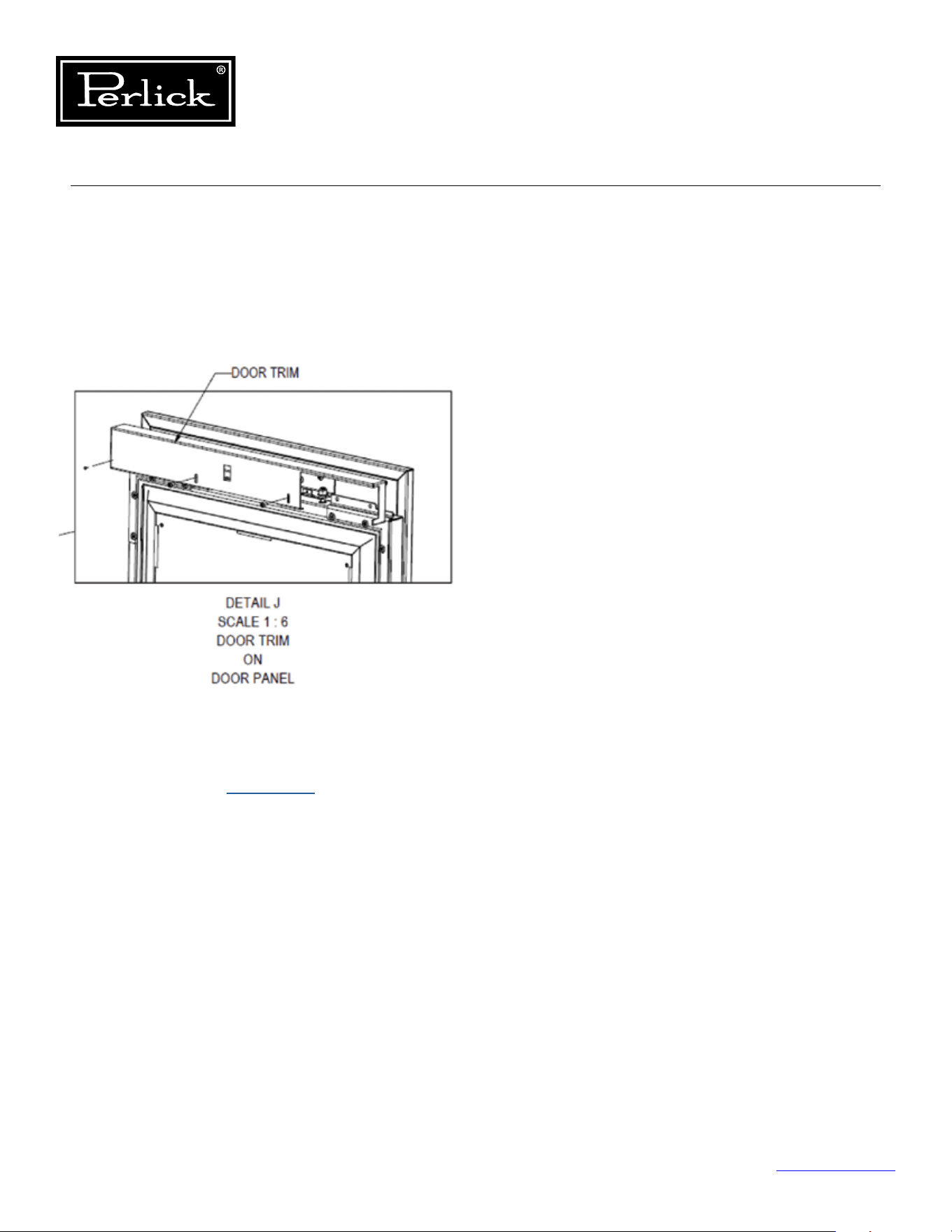
Column Refrigeration Service Manual
Return to Table of Contents
82
8.10 Replace Door Handle
To replace the door handle:
1. Remove the door trim cover at the top of the
door by removing the two fasteners.
Seegure8-9.
2. Remove the overlay from the door
(see
Overlay Panel Installation and
Adjustments - Section 8.1.)
.
3. Remove the four (4) fasteners holding the
handle to the overlay (never over-tighten the
handle mounting fasteners as this could deform
the overlay panel).
Figure 8-9. Removing door trim cover.
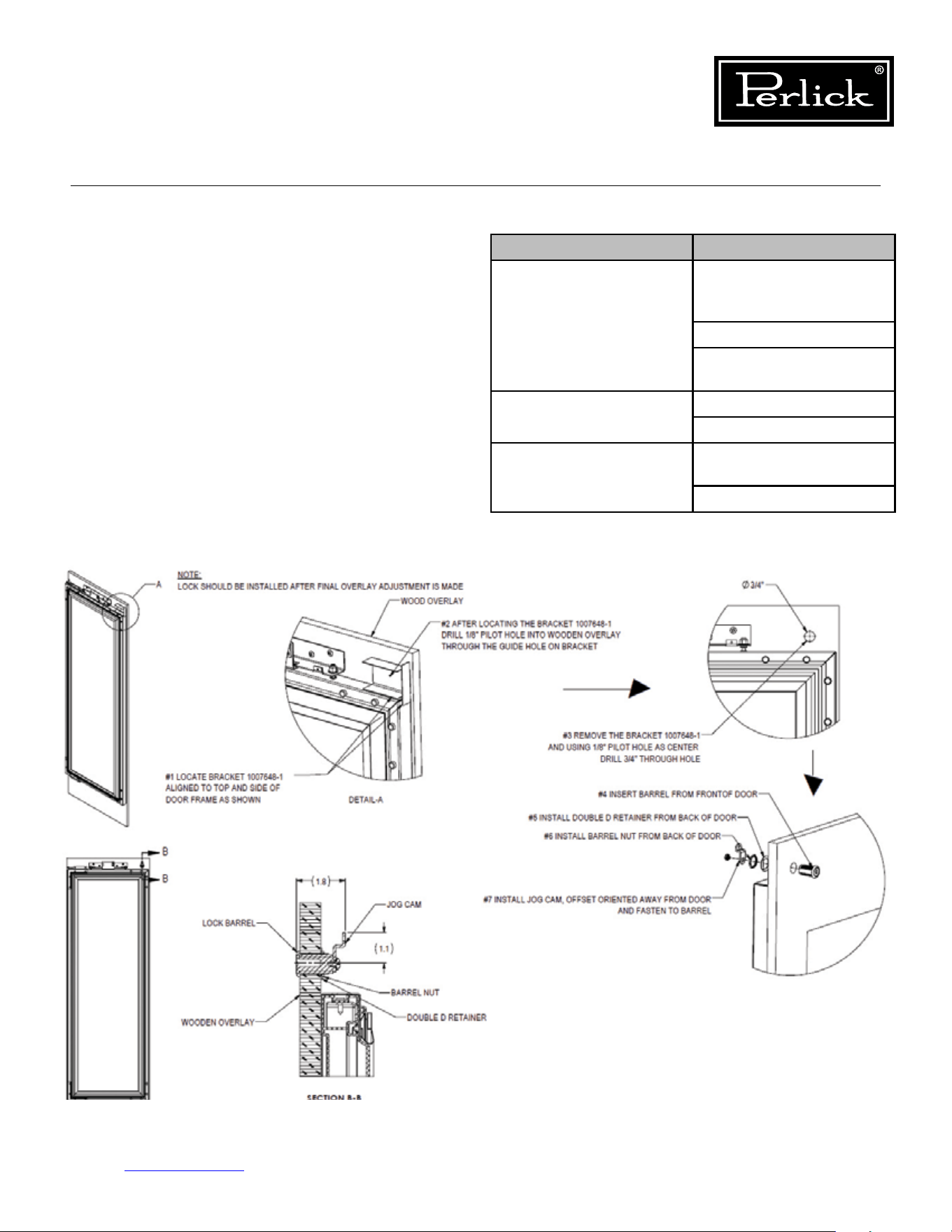
Lock Troubleshooting
Problem Cause
Lock rotates but doesn’t
engage latch
Lock misassembled and
has cam in incorrect
orientation
Cam is missing
Misalignment of cam and
catch
Lock catch interferes
with door
Catch is bent
Door is out of alignment
Key will not disengage
from lock
Lock is not installed
properly in the door
Key is over-rotated
Table 8.1. Lock Troubleshooting
Column Refrigeration Service Manual
Return to Table of Contents
83
8.11 Lock Installation
and Troubleshooting
To gain access to the lock, remove the door trim
cover from the top of the door.
See Figure 8-10.
Figure 8-10. Lock Installation

Column Refrigeration Service Manual
Return to Table of Contents
84
8.12 Custom Overlay Door Panels
Perlick columns come ready to accept customer-
supplied door panel and handle hardware.
The thickness of the custom panel can vary. A
minimum 5/8” (16mm) thick panel is required, but
the thickness can be increased provided it does
not exceed the maximum panel weight is 65 lbs
(29kg). Please note that the combined door and
overlay weight cannot exceed 242 lbs (110kg).
The depth of each model is 24” (610mm) without
anishedoverlay.Allowforpanelthicknesswhen
planningthenishedopeningdepth.Templates
for 4” and 6” solid and glass door models can be
found on pages 85-88
.
Reveals between panels can vary – 1/8” (3mm) is
the minimum.
When installing a panel thicker than 3/4” (19mm),
the 90° stop may be required to prevent damage
to the unit and adjacent cabinetry.
As reveals between cabinetry and the unit
decrease,severengerpinchingcanoccurwhile
the door is closing.
Finish sides of surrounding cabinetry — they will
be visible when the door is open. The height of
the custom door panel can extend beyond the
typical panel height provided the door and overlay
combined do not exceed 242 lbs (110kg) .
See Section 8.12.5. for screw zone for overlay
panels
. Hatch areas should provide enough
thickness for wood screw and overlay attachment
brackets.
CAUTION
CAUTION
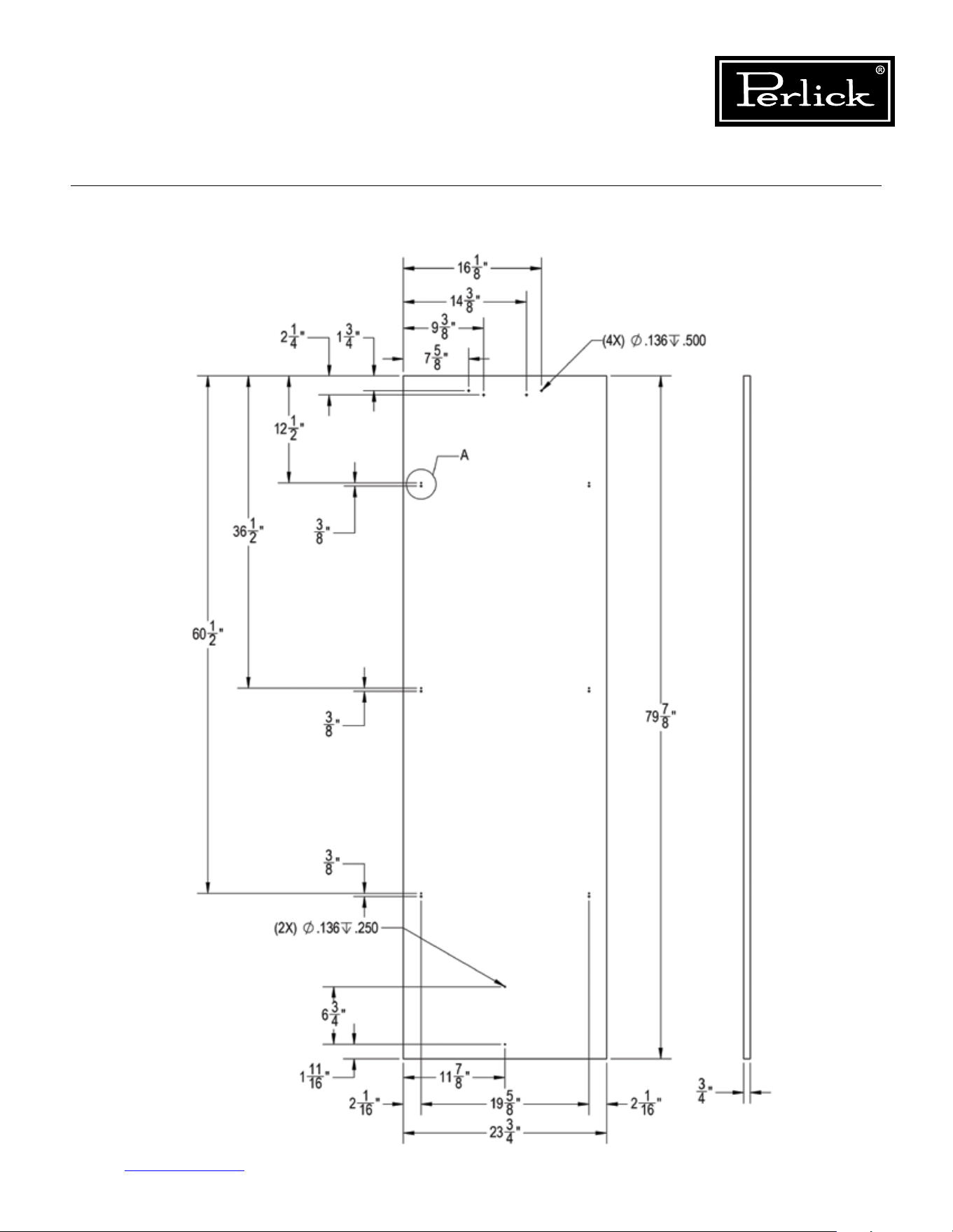
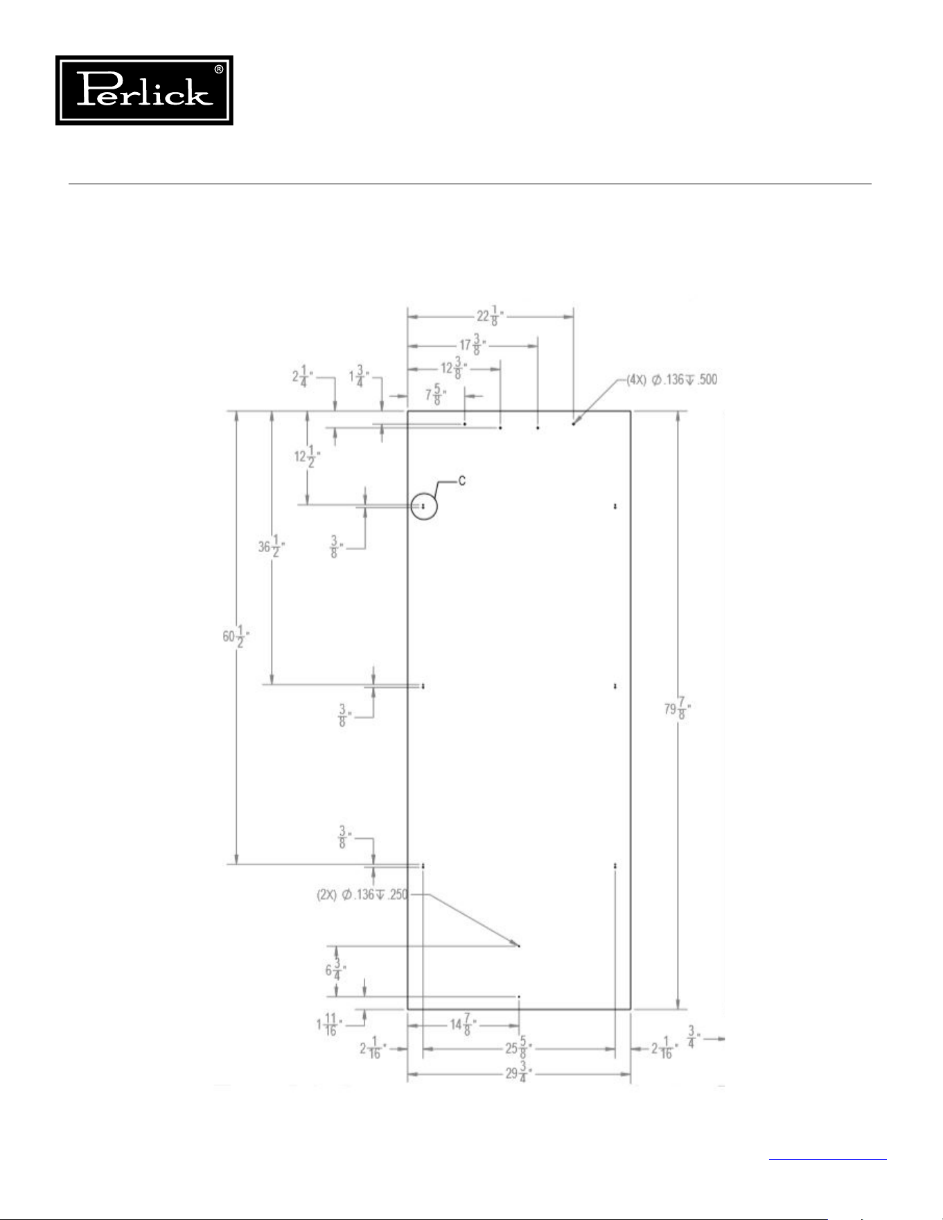
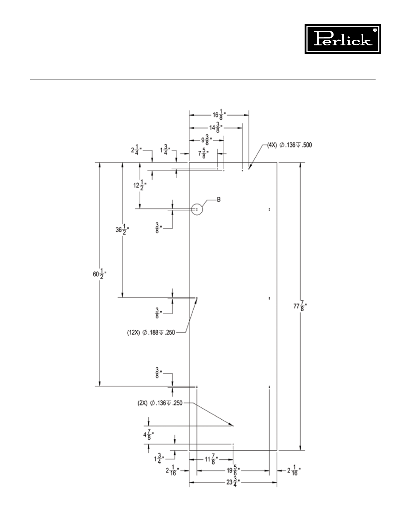
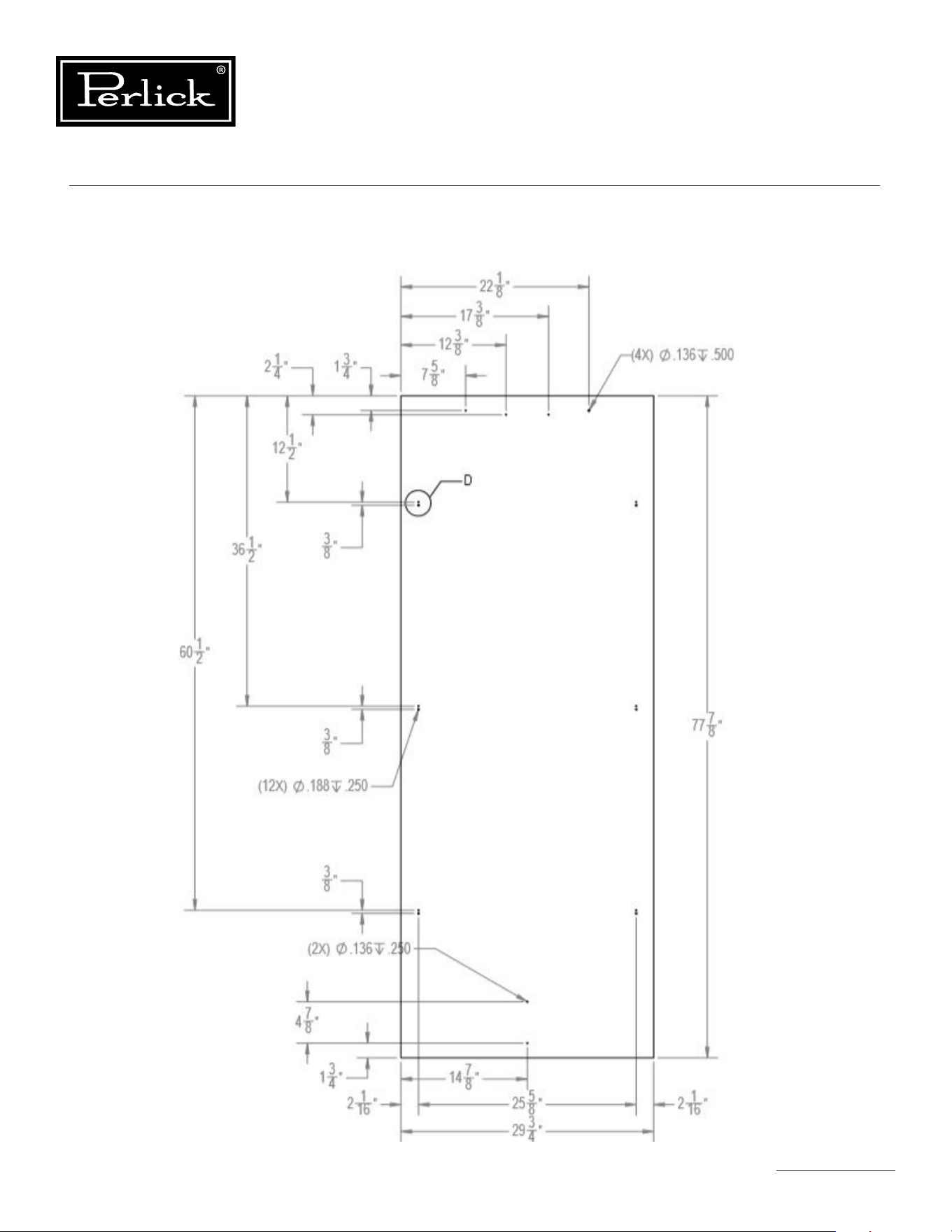
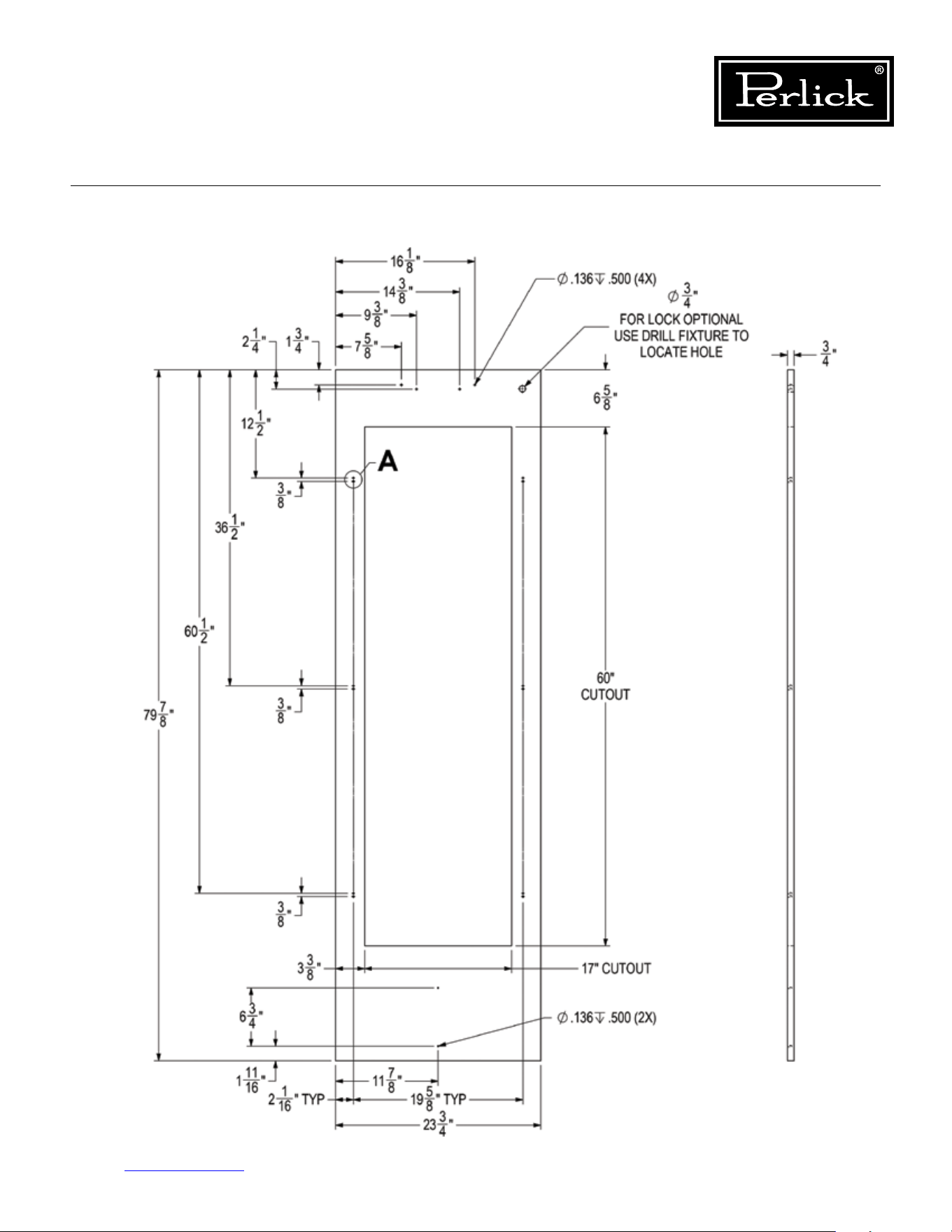
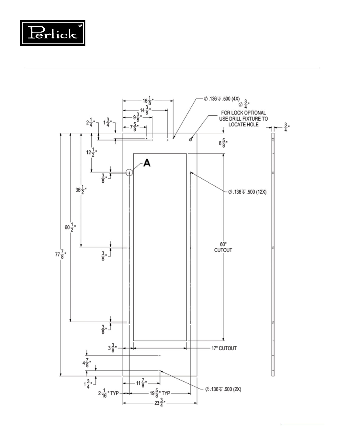
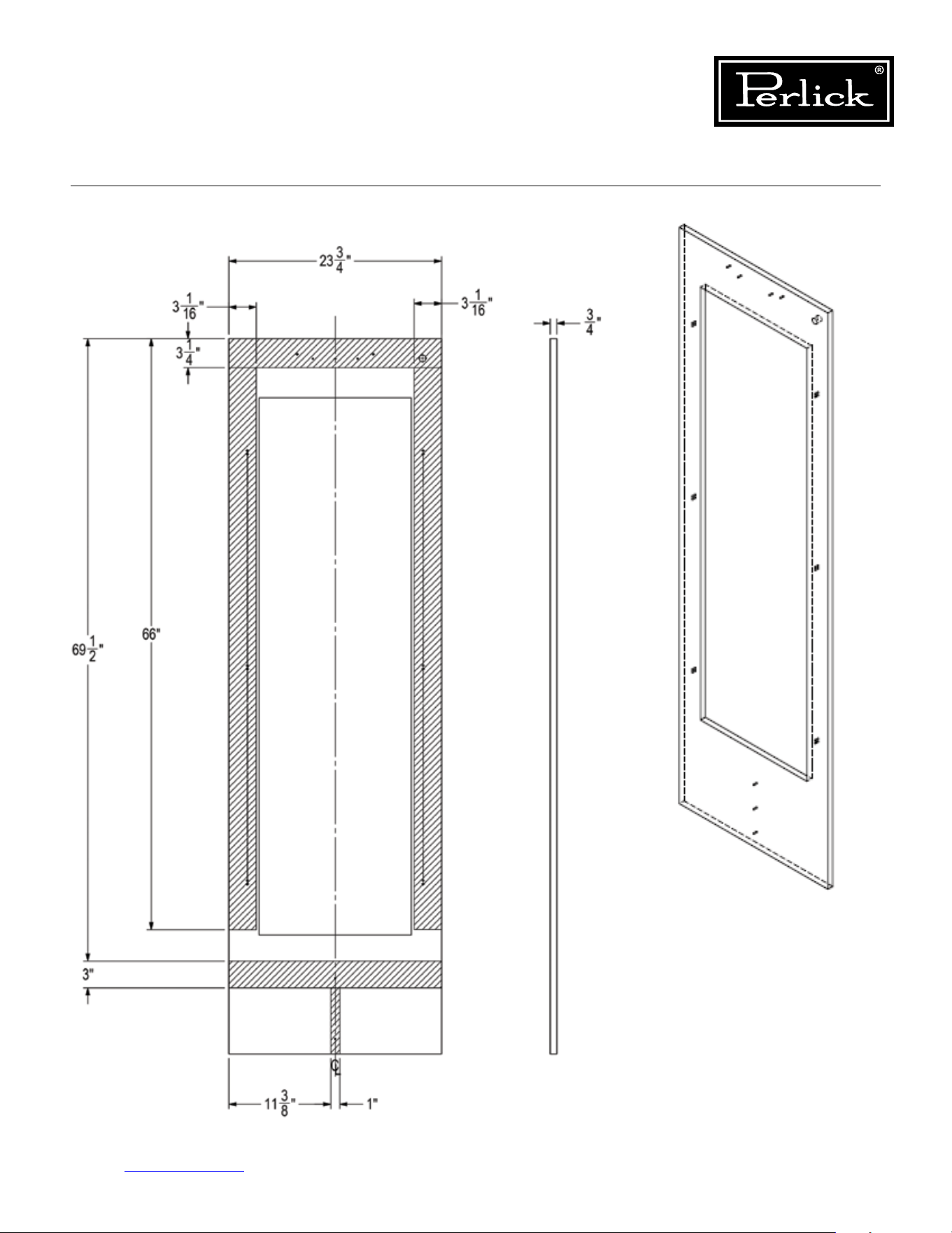
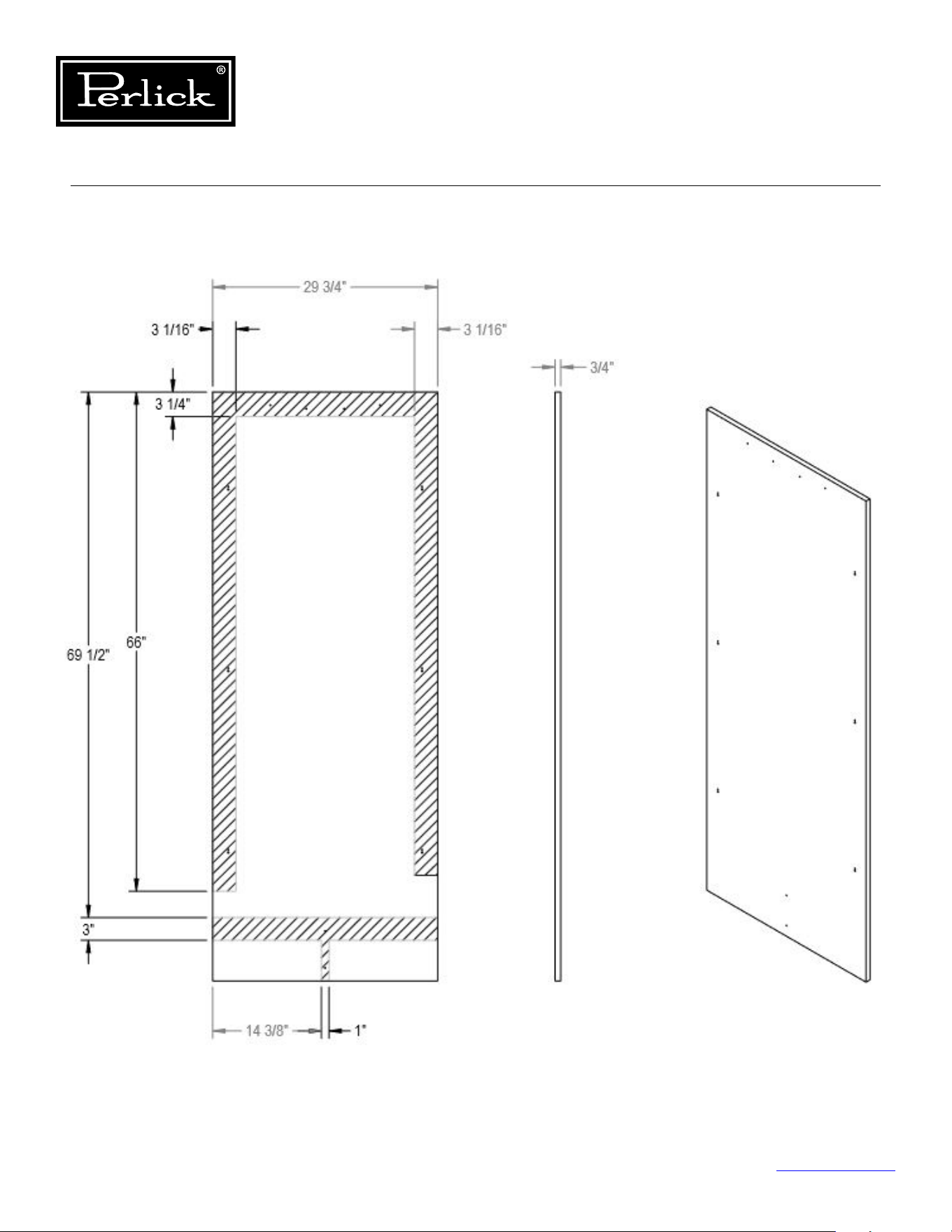
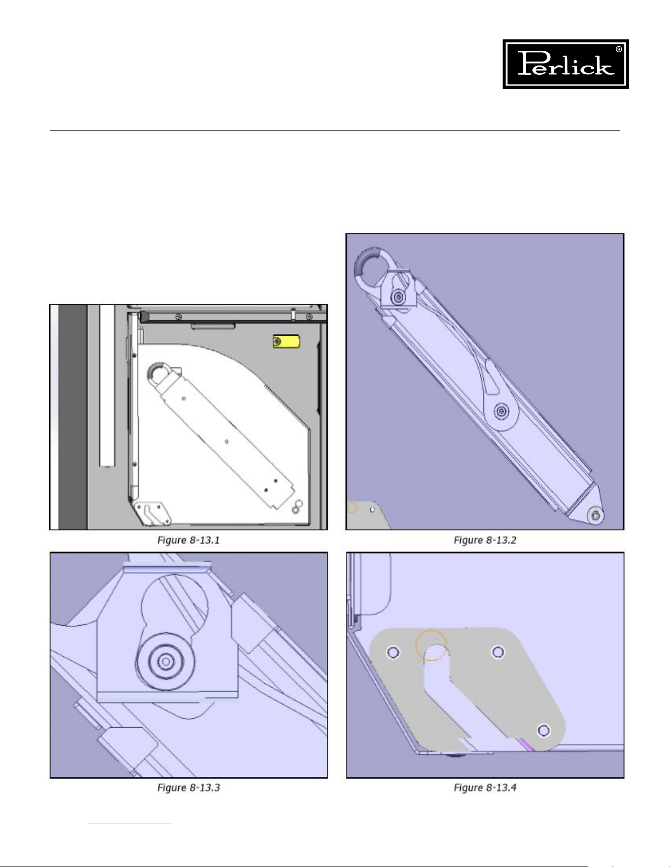
Column Refrigeration Service Manual
Return to Table of Contents
93
8.13 Tip-Out Bins
Removal - Slide Tip-Out Bin
To remove tip-out bin, tip bin out, pull out and
rotate down on spring steel stop bracket to
disengage stop. When stop is disengaged, bin will
tip-out further. Once the slides are fully extended,
remove the slide from the key hole slot on each
side of the bin. Lift up and pull the bin towards
you to disengage the pivot blocks from the pivot
fastener.
Seegures8-13.1through8-13.4.
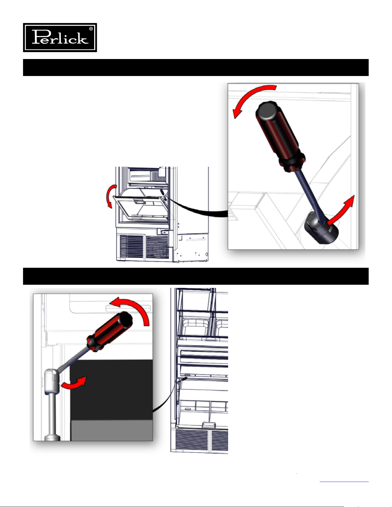
Column Refrigeration Service Manual
Return to Table of Contents
94
1. ROTATE THE BIN ALL THE WAY DOWN, SO IT IS RESTING ON
THE BOTTOM OF THE CABINET FULLY OPEN.
2. LOCATE THE END FITTING ON THE GAS SPRING ON THE LEFT
SIDE OF THE BIN AND USING THE FLAT HEAD SCREWDRIVER,
RELEASE THE END FITTING BY PLACING THE FLAT HEAD
SCREWDRIVER INTO THE RELEASE LATCH AND PRYING
OUTWARD TO DISENGAGE THE END FITTING FROM THE
CABINET WALL FITTING.
Removal - Damper Tip-Out Bin
Operation #1
Operation #2
1. Rotate the bin all the way down, so it is
resting on the bottom of the cabinet fully
open.
2. Locatetheendttingonthegasspringon
theleftsideofthebinandusingtheat
headscrewdriver,releasetheendtting
byplacingtheatheadscrewdriverinto
the release latch and prying outward to
disengagetheendttingfromthecabinet
walltting.
1. Remove all contents from the tip-out bin, including glass
divider and bottom panel.
2. Open tip-out bin until the right side damper end is showing.
3. While supporting the tip-out bin, locate the damper end
ttingontherightside.Usingaatheadscrewdriver,
releasetheendttingonthedamper,byplacingtheat
head screwdriver into the release latch and prying inward to
disengagetheendttingfromthebintting.
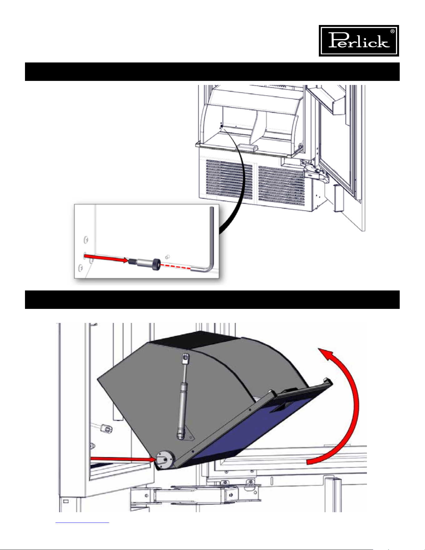
Column Refrigeration Service Manual
Return to Table of Contents
95
Operation #3
Operation #4
1. Once retainer fasteners are removed, tilt the tip-out bin up and pull out towards you to remove.
1. Using the 5/32” allen wrench, remove the left
and right shoulder bolts located inside the
bottom front of the bin.
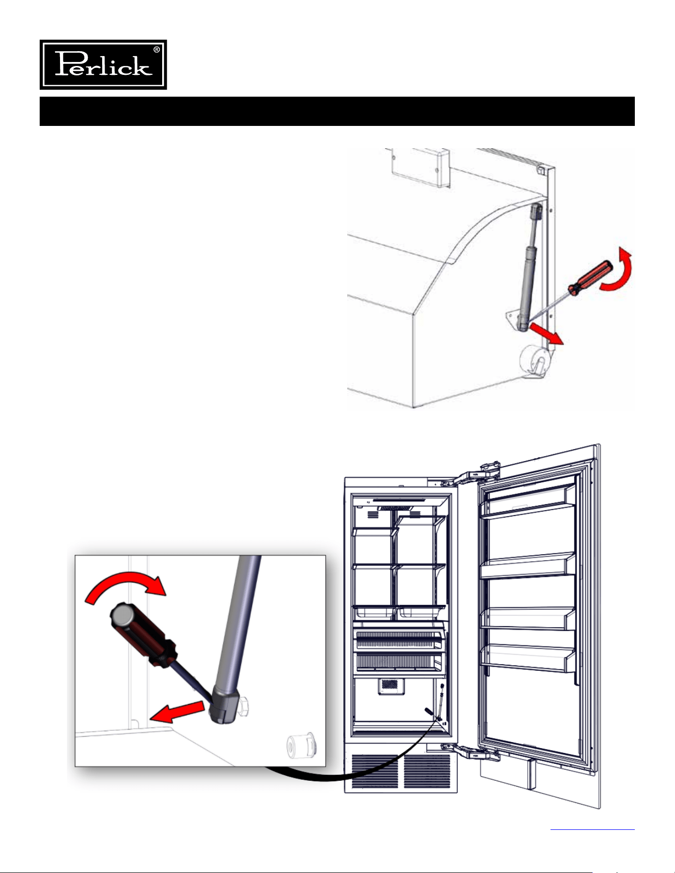
Column Refrigeration Service Manual
Return to Table of Contents
96
Operation #5
THE FOLLOWING STEPS ARE
TO REPLACE THE GAS SPRING
AND DAMPER ONLY. SKIP TO
OPERATION #6 FOR TIP-OUT
BIN ASSEMBLY.
1. Locatetheendttingonthegasspringontheleft
sideofthebinandusingtheatheadscrewdriver,
releasetheendttingbyplacingtheathead
screwdriver into the release latch and prying
outwardtodisengagetheendttingfromthebin
wall ball stud.
2. Locatethedamperendttingontherightsideof
thecabinet.Usingaatheadscrewdriver,release
theendttingonthedamper,byplacingtheat
head screwdriver into the release latch and prying
inwardtodisengagetheendttingfromthebin
ball stud.
3. Once removed, press & snap the new gas spring or
damper back onto the ball stud.
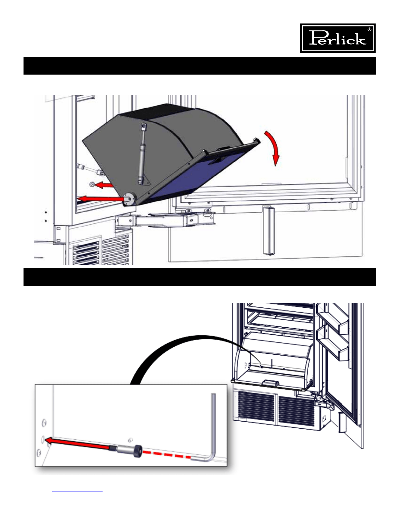
Column Refrigeration Service Manual
Return to Table of Contents
97
Operation #6
Operation #7
1. Place tip-out bin into position by placing left and right guide blocks on bin over pivot bushing in cabinet. Allow
tip-out bin to rest on bottom of cabinet.
1. Install left and right shoulder bolts using 5/32” allen wrench and tighten snuggly.
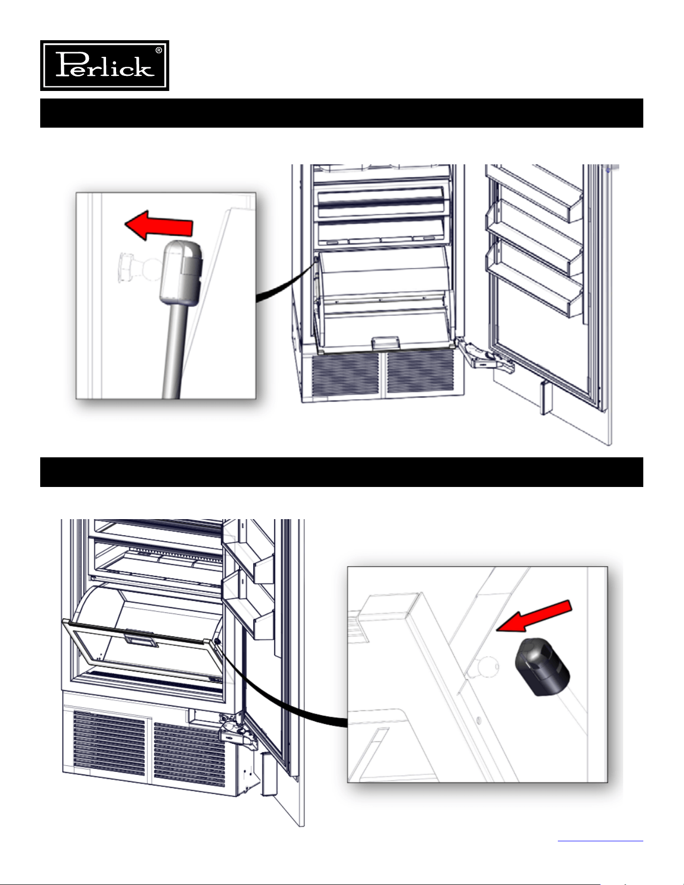
Column Refrigeration Service Manual
Return to Table of Contents
98
Operation #8
Operation #9
1. Withthetipoutbinrotatedallwayopen,installtheleftsidedamperontothecabinetwallttingbysnappingit
ontothetting.
1. Pivottip-outbinapproximately45degrees,sorightsidedamperendttingalignswithbintting
and snap into place.
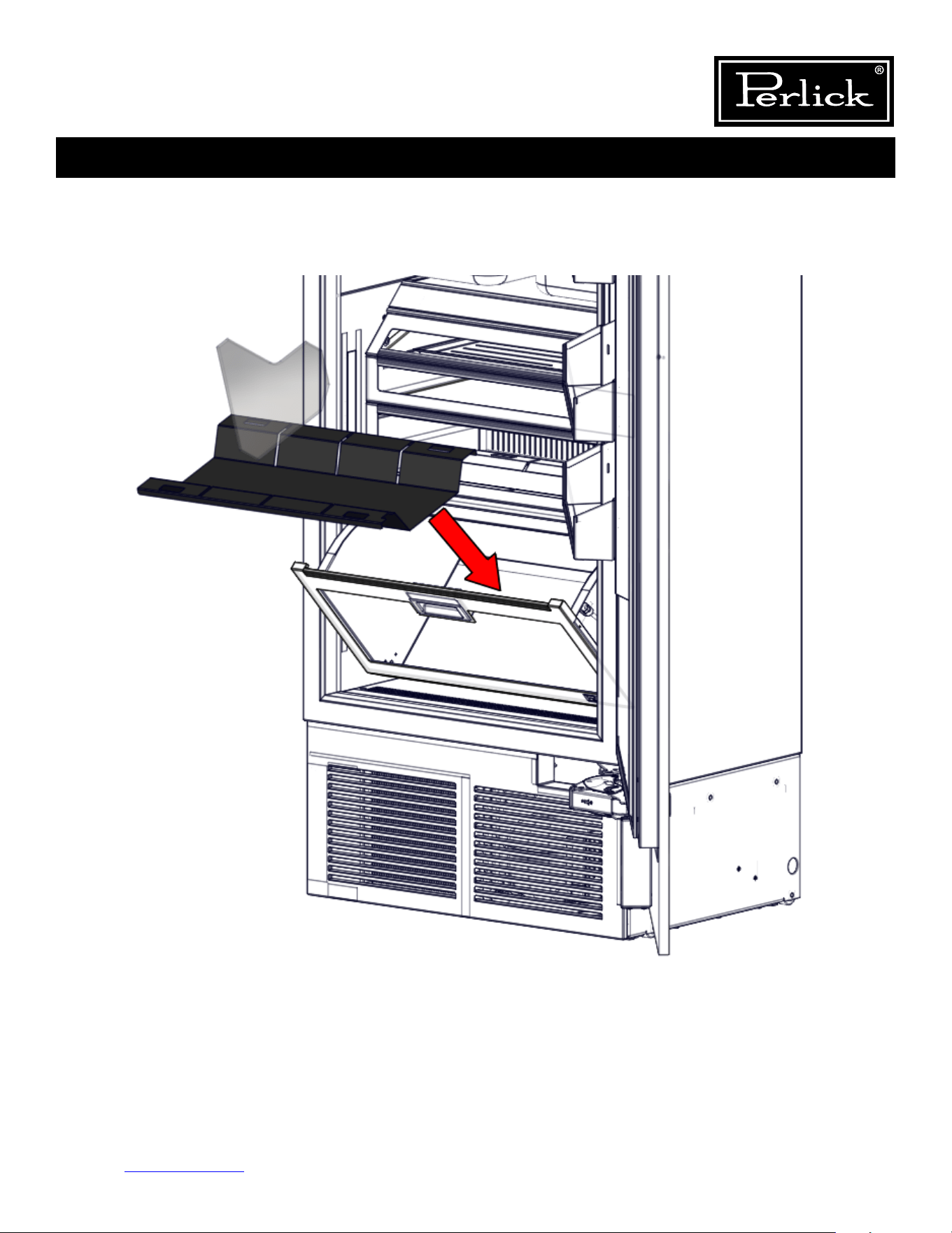
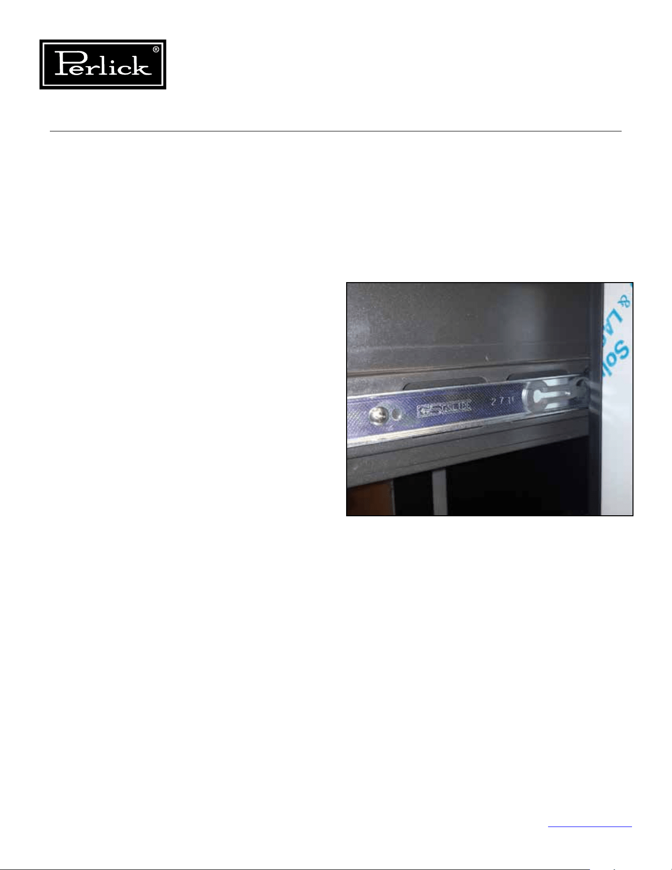
Column Refrigeration Service Manual
Return to Table of Contents
100
8.14 Drawers
8.14.1 Deli And Meat Drawer
The deli and meat drawers on the refrigerator use
push to open slides. To open, push inward on the
face of the drawer and release and the slide will
push open the drawer.
Removal
Toremovethedelidrawerap,partiallyopen
thedrawerandliftupontheap,removethe
pivot fastener on the left and right ends of the
ap.Alwayssupporttheapwhenremovingthe
fasteners.
To remove the deli and meat drawers, push to
open and then full extend the drawer, located the
release mechanism on each slide and pull forward
on the release mechanisms and pull the drawer
out. To remove the slide member from the cabinet
side wall, locate the mounting screws and remove.
Support the slide to avoid scratching the side wall
of the cabinet.
Reinstallation
To reinstall the drawers, line up the drawer
slide member with the cabinet slide member,
slide together gently, ensuring that the drawer
slide member is parallel with the cabinet slide
member. Do not force together as this can result
in damage to the ball bearing retainer and result
in ball bearings dislodging from the retainer. Once
engaged, push the drawer in all the way and
then push to open and pull the drawer out to full
extension to ensure the slide lock mechanism is
engaged.
Figure 8-14 - Deli And Meat Drawer Release
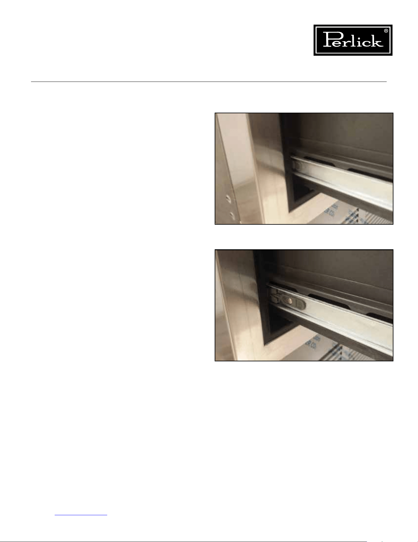
Column Refrigeration Service Manual
Return to Table of Contents
101
8.14.2 Freezer Drawers
Removal
To remove the freezer drawers, pull out on the
drawer until fully extended, locate the release
mechanism on each slide and pull forward on the
release mechanisms and pull the drawer out. To
remove the slide member from the cabinet side
wall, locate the mounting screws and remove.
Support the slide to avoid scratching the side wall
of the cabinet.
Reinstallation
To reinstall the drawers, line up the drawer
slide member with the cabinet slide member,
slide together gently, ensuring that the drawer
slide member is parallel with the cabinet slide
member. Do not force together as this can result
in damage to the ball bearing retainer and result
in ball bearings dislodging from the retainer. Once
engaged, push the drawer in all the way and then
pull the drawer out to full extension to ensure the
slide lock mechanism is engaged.
Figure 8-15.1 - Freezer Drawer Slide
Figure 8-15.2 - Freezer Drawer Release
Column Refrigeration Service Manual
Return to Table of Contents
102
8.15 Drawer Compartment Dividers
To remove the drawer compartment dividers
(insulated dividers between each drawer):
1. Locate the two retaining pins on the left and
right sides approximately 2/3 back on the
divider extrusions.
2. Remove the two retaining pins by prying up
usingaatbladescrewdriver(protectmaterial
surfaces to avoid scratches) and then pulling
the pins out.
3. Pull forward on the divider and disconnect the
light electrical connection.
4. Pull the divider out of the cabinet.
To install:
1. Slide divider into cabinet extrusion
2. Make light electrical connection
3. Manage excess wire and slide divider in until
completely inserted.
4. Install the two retaining pins.
Figure 8-16 - Drawer Compartment Divider
And Retaining Pin
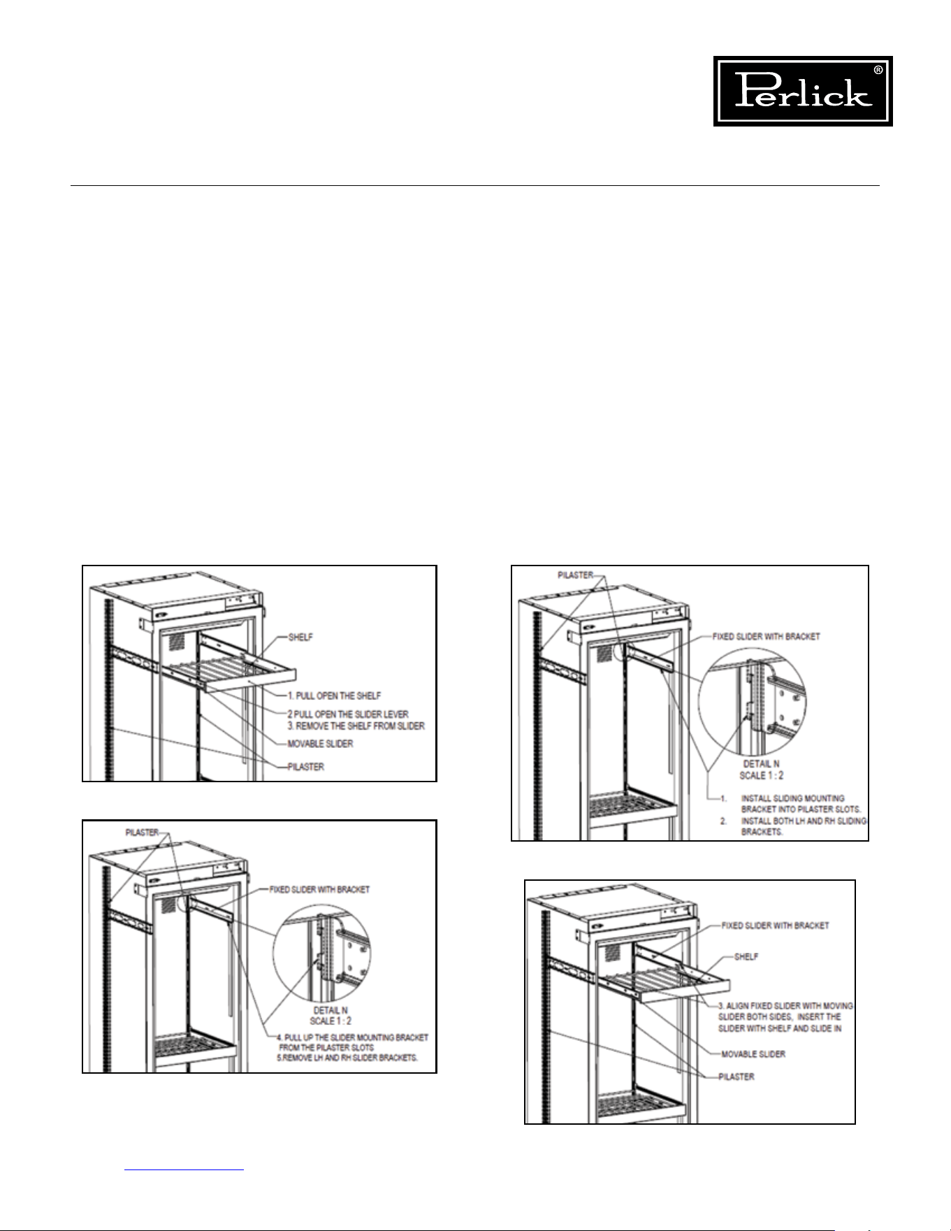
Column Refrigeration Service Manual
Return to Table of Contents
103
8.16 Shelving
8.16.1 Wine Shelving
The wine reserves use soft-close full extension
slides. Never force the slide all the way closed
as this can cause damage to the soft-close
mechanism.
Removal
To remove the wine shelves, pull on the shelf
and fully extend. Locate the release mechanism
on each slide and pull forward on the release
mechanisms and pull the shelf out. To remove
the slide member from the cabinet pilaster, simply
lift-up evenly and pull forward. Support the slide to
avoid scratching the side wall of the cabinet.
Reinstallation
Toreinstalltheshelves,rstinstallthecabinet
slide assemblies into the pilasters, next, line up
the shelf slide members with the cabinet slide
members, slide together gently, ensuring that the
shelf slide member is parallel with the cabinet slide
member. Do not force together as this can result
in damage to the ball bearing retainer and result
in ball bearings dislodging from the retainer. Once
engaged, push the shelf in until shelf slide is fully
retracted, then pull the shelf out to full extension
to ensure the slide lock mechanism is engaged.
Finally, push the shelf in until the soft-close
mechanism engages and fully retracts the shelf
into position.
Figure 8-17.1. Remove Wine Shelves
Figure 8-17.2. Remove Wine Shelves
Figure 8-17.3. Install Wine Shelves
Figure 8-17.4. Install Wine Shelves
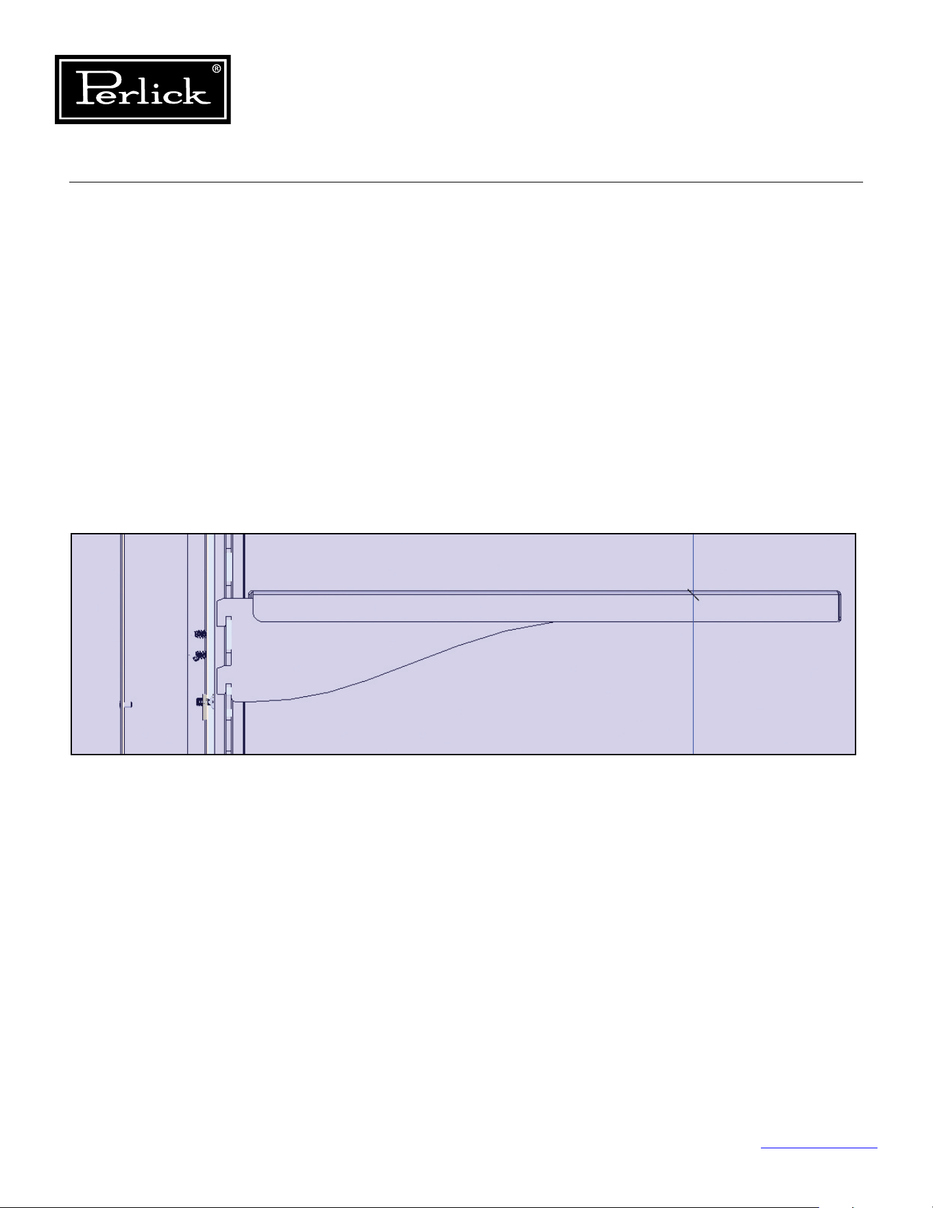
Column Refrigeration Service Manual
Return to Table of Contents
104
8.16.2 Freezer Shelving
The freezer shelves are simple single piece design,
cantilever shelves.
Removal
To remove, simply lift-up squarely on the shelf and
pull forward to remove from the pilasters.
Installation
To install, align shelf brackets with pilasters and
slide down into pilaster, ensure all for attachment
points are engaged.
Figure 8-18. Freezer Shelving
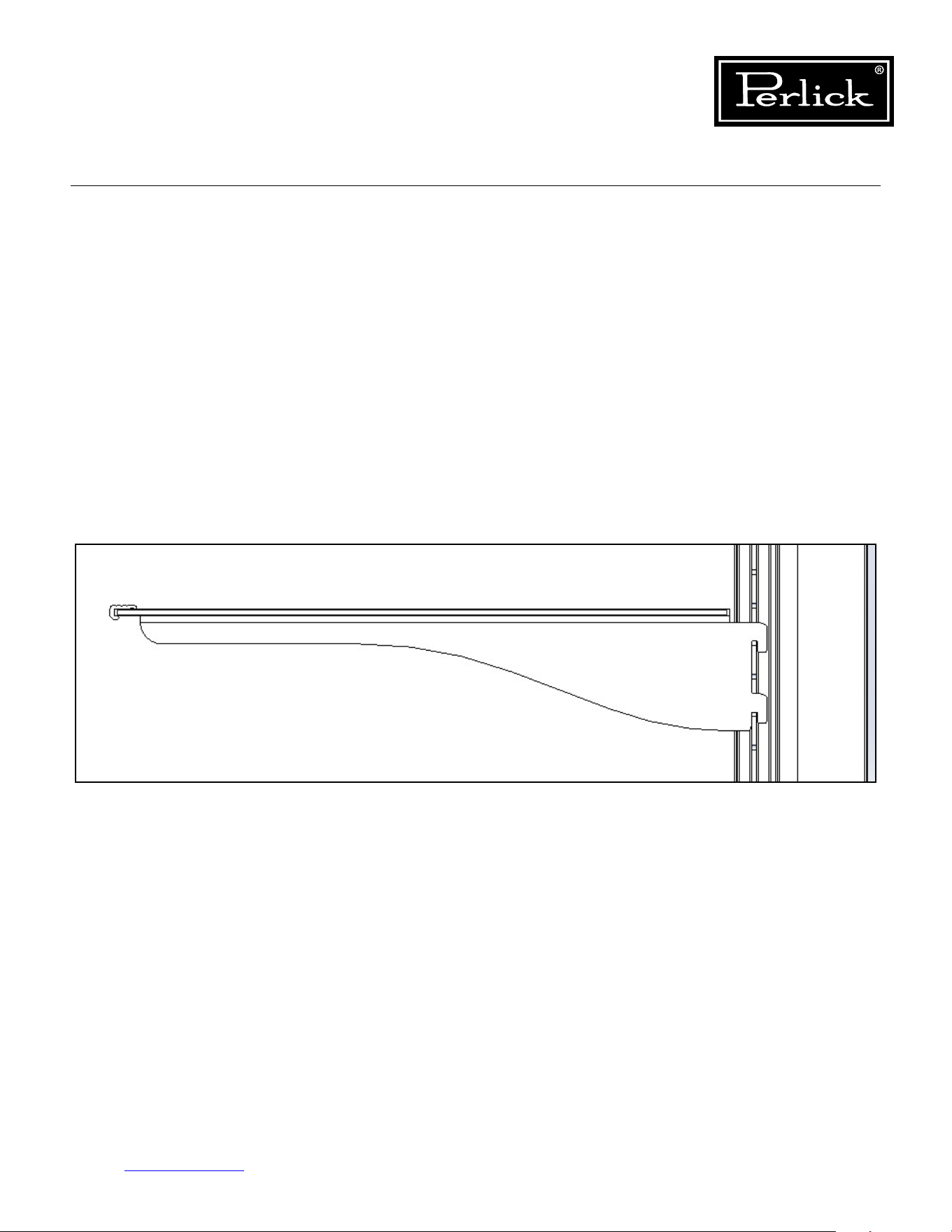
Column Refrigeration Service Manual
Return to Table of Contents
105
8.16.3 Refrigerator Shelving
The wine reserves use soft-close full extension
slides. Never force the slide all the way closed
as this can cause damage to the soft-close
mechanism.
Removal
To remove the wine shelves, pull on the shelf
and fully extend. Locate the release mechanism
on each slide and pull forward on the release
mechanisms and pull the shelf out. To remove
the slide member from the cabinet pilaster, simply
lift-up evenly and pull forward. Support the slide to
avoid scratching the side wall of the cabinet.
Reinstallation
Toreinstalltheshelves,rstinstallthecabinetslide
assemblies into the pilasters, next, line up the shelf
slide members with the cabinet slide members,
slide together gently, ensuring that the shelf slide
member is parallel with the cabinet slide member.
Do not force together as this can result in damage to
the ball bearing retainer and result in ball bearings
dislodging from the retainer. Once engaged, push the
shelf in until shelf slide is fully retracted, then pull
the shelf out to full extension to ensure the slide lock
mechanism is engaged. Finally, push the shelf in until
the soft-close mechanism engages and fully retracts
the shelf into position.
Figure 8-19. Refrigerator Shelving
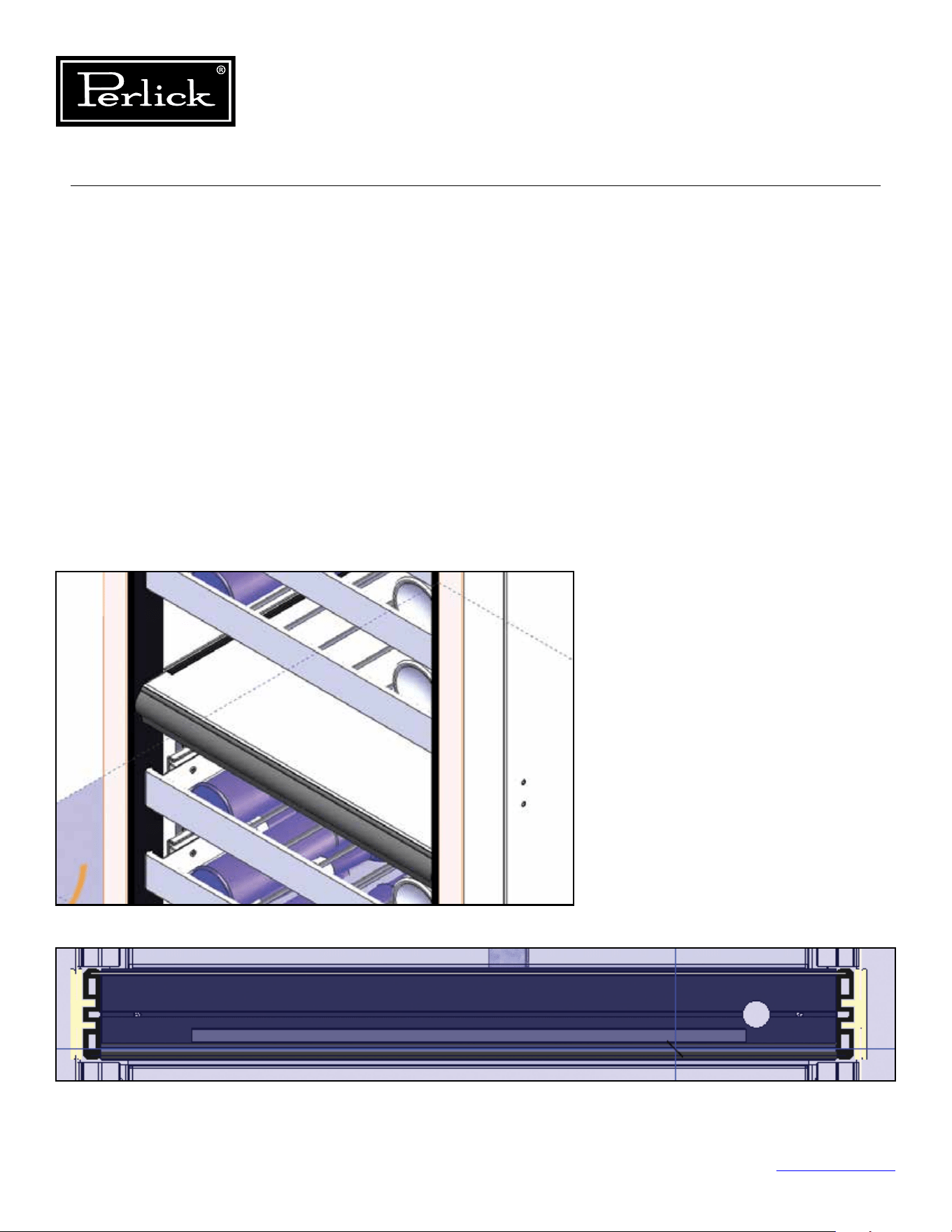
Column Refrigeration Service Manual
Return to Table of Contents
106
8.17 Dual-Zone Wine
Compartment Divider
Removal
To remove the dual zone wine compartment
divider, locate the two fasteners on the bottom left
and right edges and remove. Pull out on the divider
and disconnect the light electrical connector.
Remove divider from the cabinet.
Installation
To install, slide divider into cabinet extrusions,
make light electrical connection, manage excess
wireandpushdividerintocabinetuntilushwith
back wall. Install retaining fasteners into bottom
left and right edges.
Figure 8-20.1. Dual-Zone Compartment Divider
Figure 8-20.2. Dual-Zone Compartment Divider
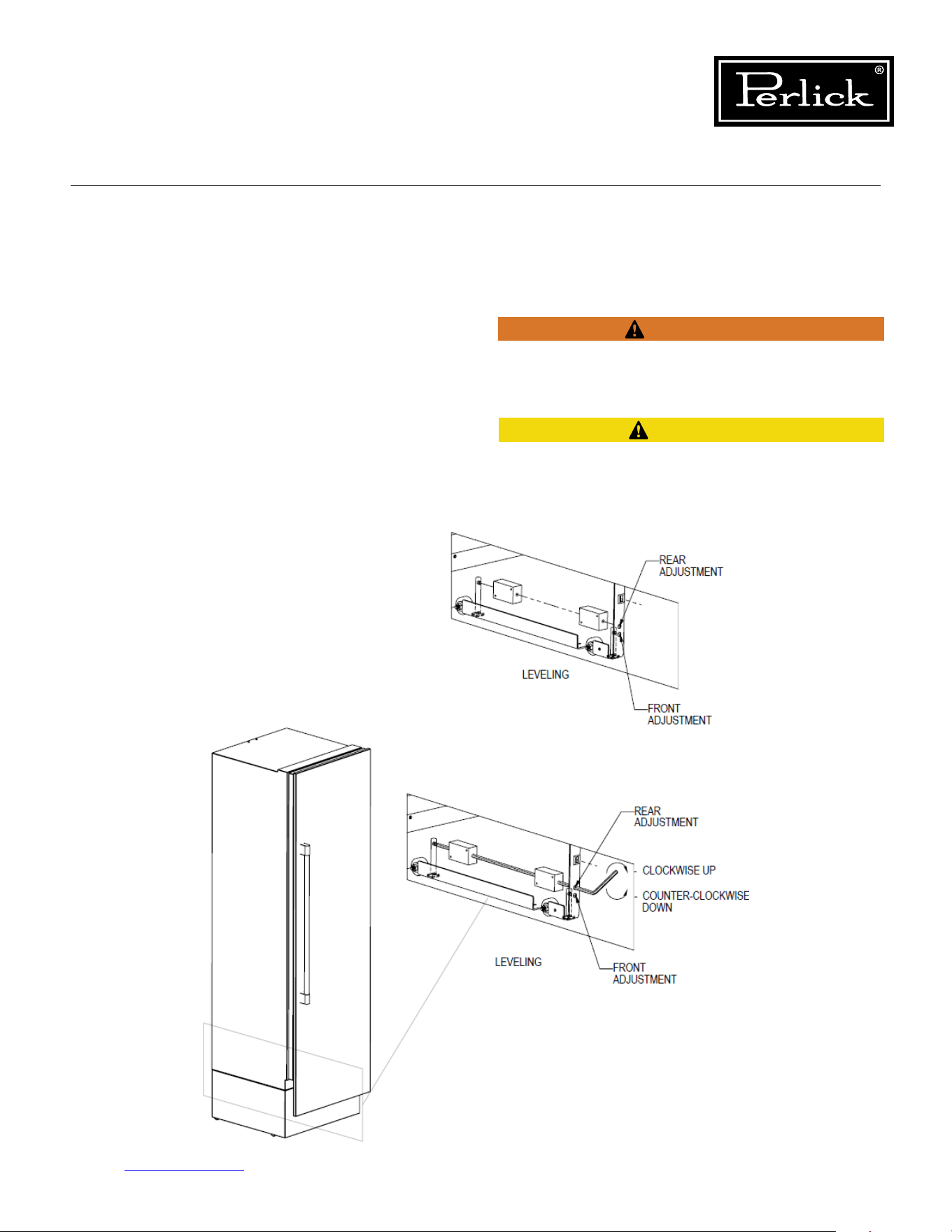
Column Refrigeration Service Manual
Return to Table of Contents
107
8.18 Leveling/Alignment
Move the unit near the opening. Plug the power
cord into the grounded outlet and roll the unit into
position. Push unit into place.
Front and rear leveling legs can be adjusted from
the front once the unit is positioned. To access
leveling adjustment access holes, remove toe kick
grill.
Once the unit is in position, height adjustment
can be made from the front. Using the hex driver
leveling tool, turn clockwise to raise the unit or
counterclockwise to lower.
Seegure8-21
.
When the unit is properly leveled, door adjustments
are less likely to be needed.
To reduce the possibility of the unit tipping forward,
the front leveling legs must be in contact with the
oor.
The refrigerated cabinet should be level for proper
operation, such as door closing, drawer and shelf
slide operation.
CAUTION
WARNING
Figure 8-21. Leveling/Alignment
Column Refrigeration Service Manual
Return to Table of Contents
108
Verify there are no electrical wires or plumbing in the
area which the screws could penetrate.
Always wear safety glasses and use other necessary
protective devices or apparel when installing or
working with anchors. Anchors are not recommended
for use in lightweight masonry material such as block
or brick, or for use in new concrete which has not
hadsucienttimetocure.Theuseofcoredrillsis
not recommended to drill holes for anchors.
Before moving unit into position, secure the door
closedandprotectanynishedooring.
Use an appliance dolly to move the unit near the
opening.
8.19 Cabinet Anti-Tip/Anti-Tip Bracket
To prevent the unit from tipping forward, the
anti-tip bracket must be installed. Use all anti-tip
bracket hardware as instructed. Level as instructed
on
Page 98
prior to installing anti-tip bracket(s)
The anti-tip bracket and supporting hardware
is included with your unit. Please note that four
anti-tip brackets are required for each unit or dual
installation. In the case of dual installation, each
individualunitmustbeoutttedwiththetwoanti-
tip brackets on cabinet sides for a total of four.
For drawings of the anti-tip bracket installation
on integrated (built-in) units,
see Page 100
. For
drawings of the anti-tip bracket installation on
freestanding units,
see Page 101
.
CAUTION
WARNING
WARNING
CAUTION
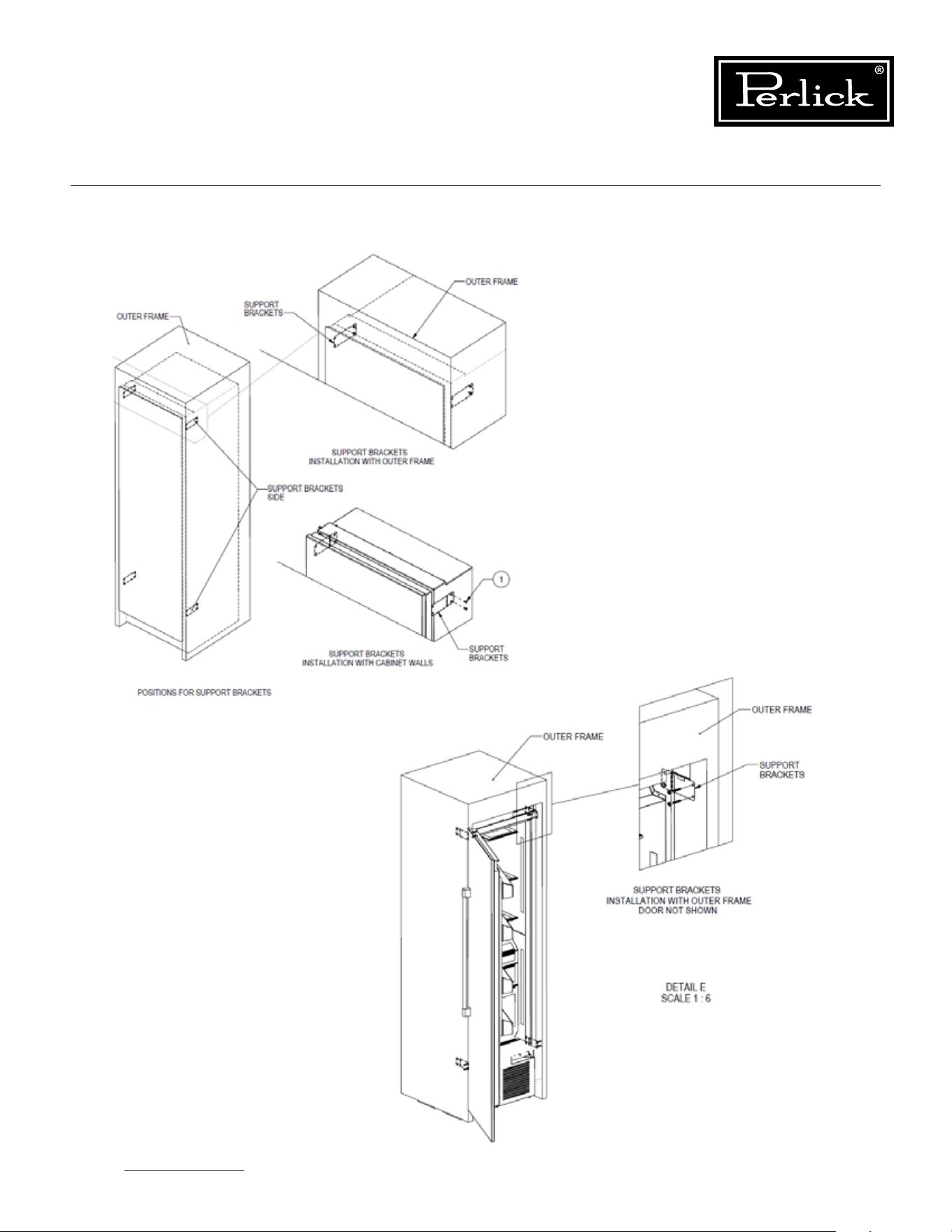
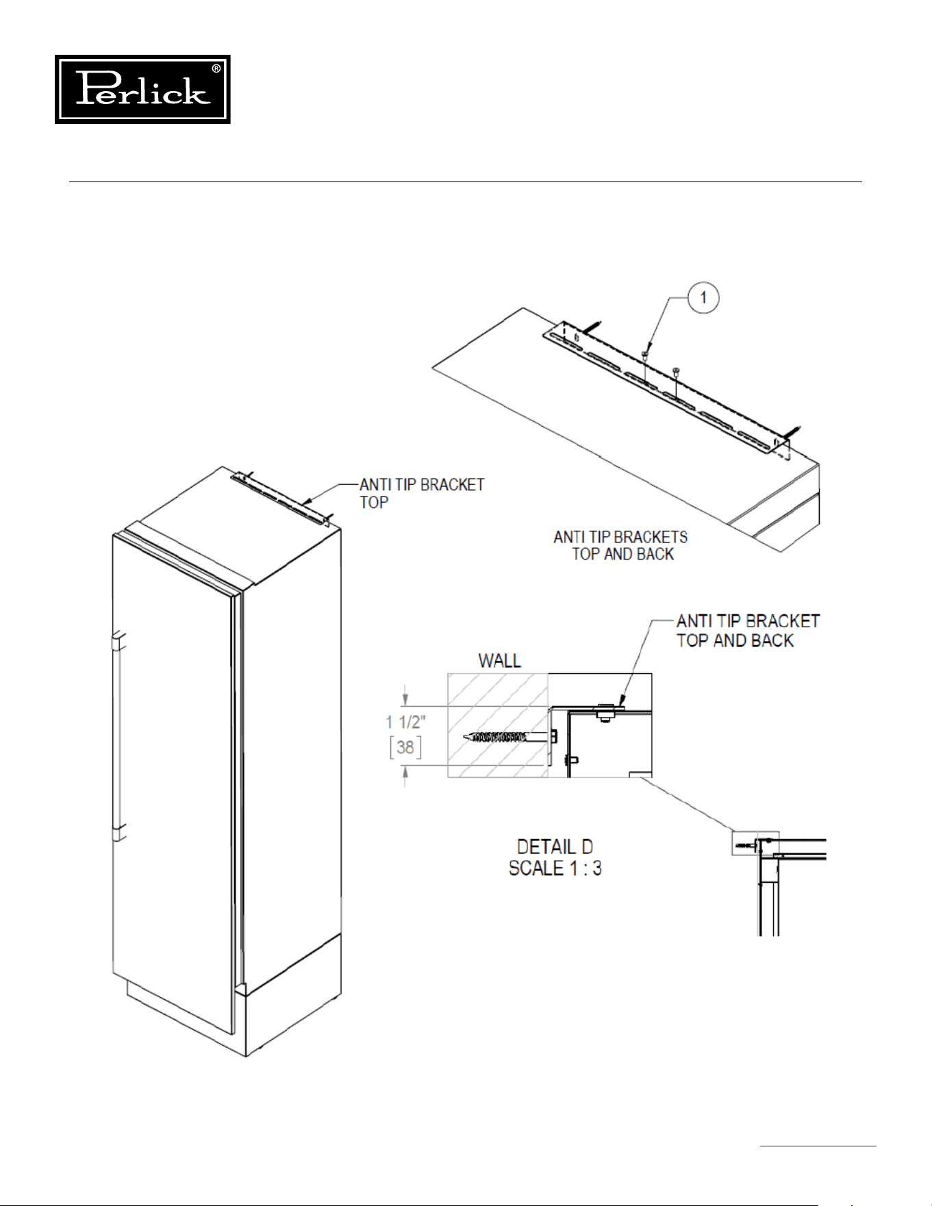
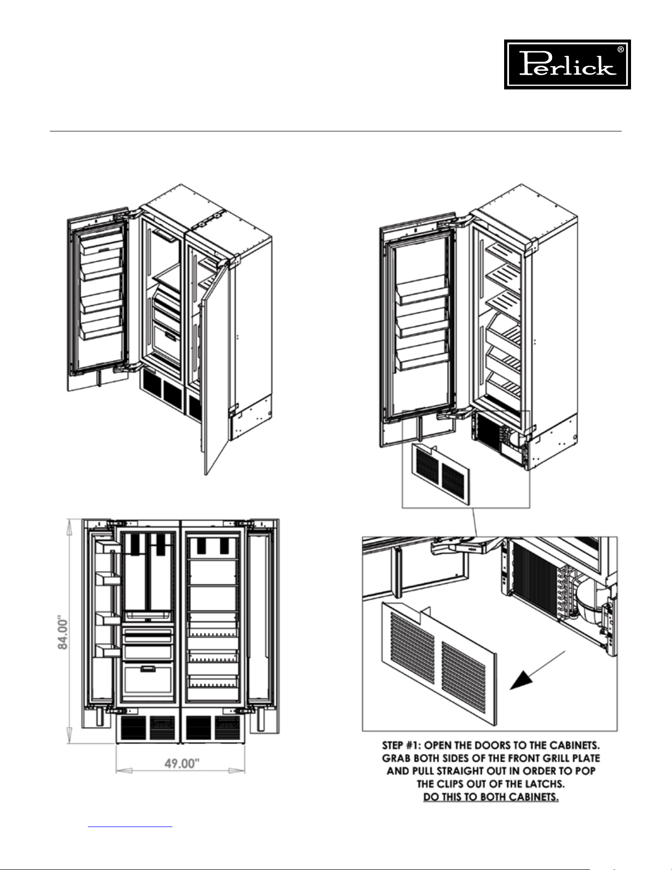
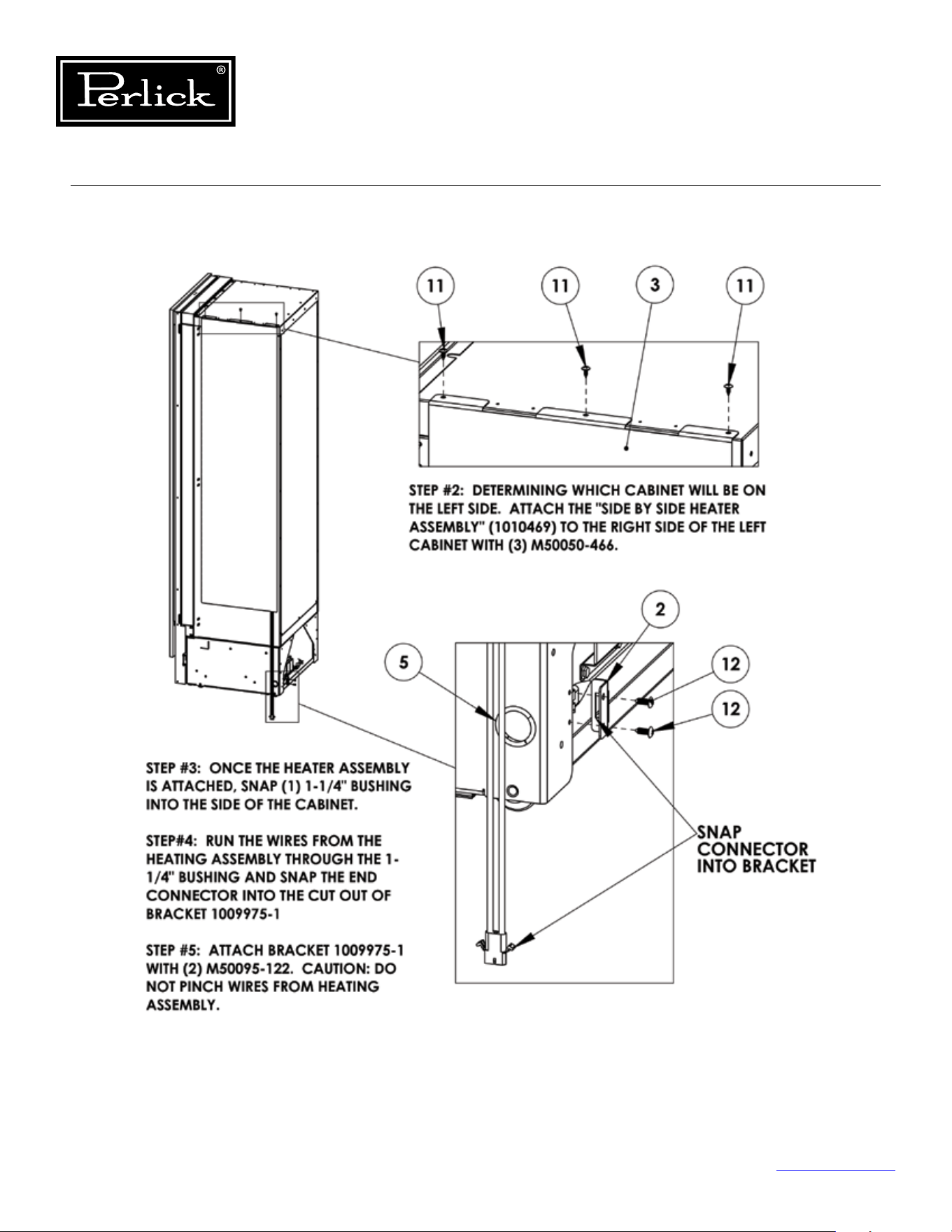
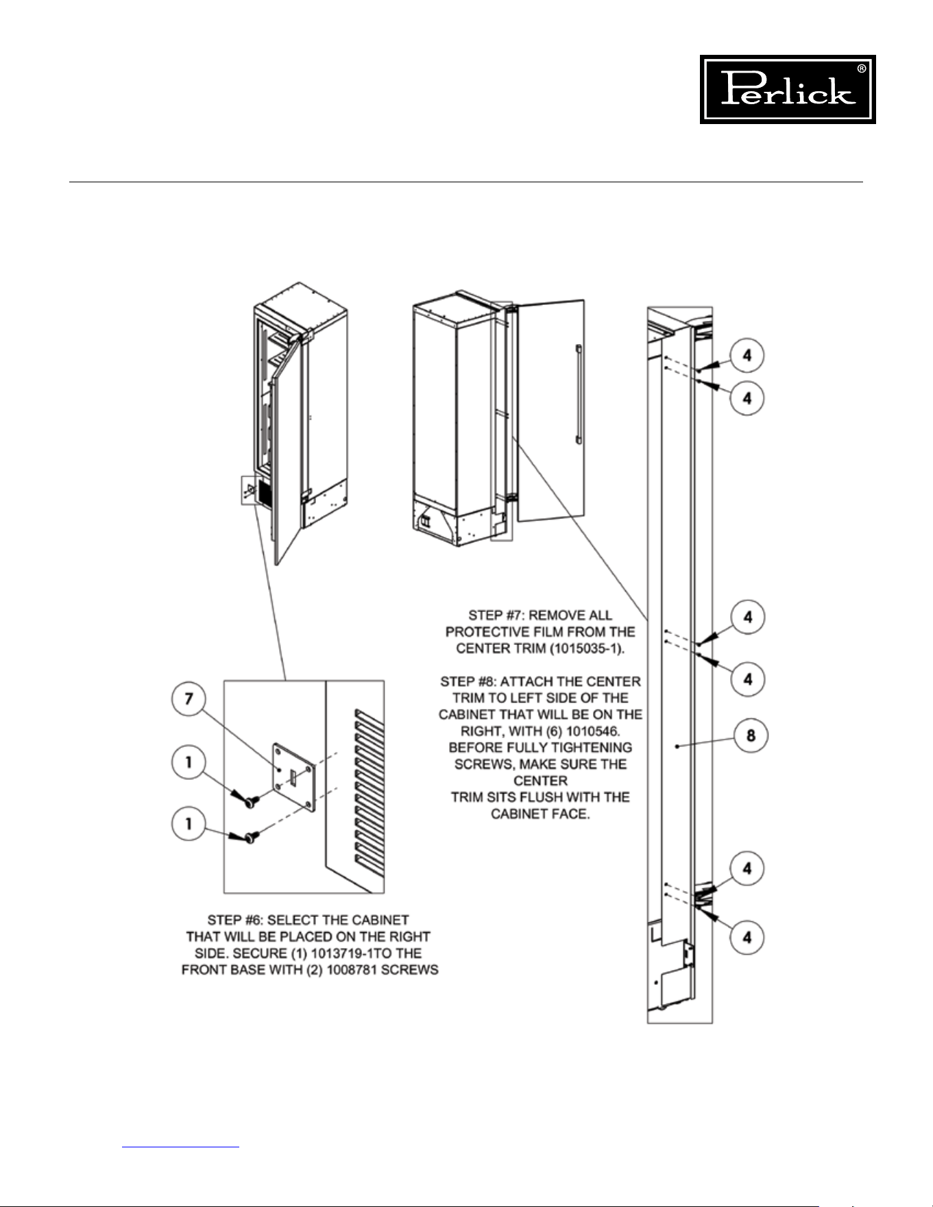
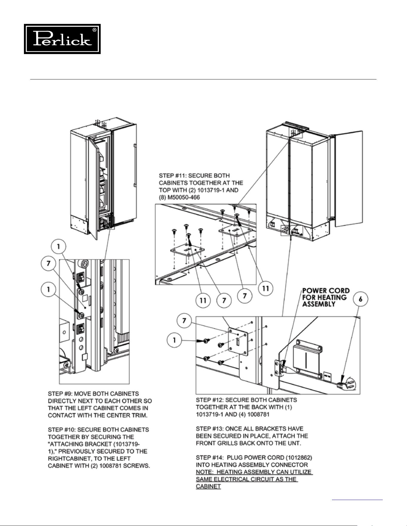
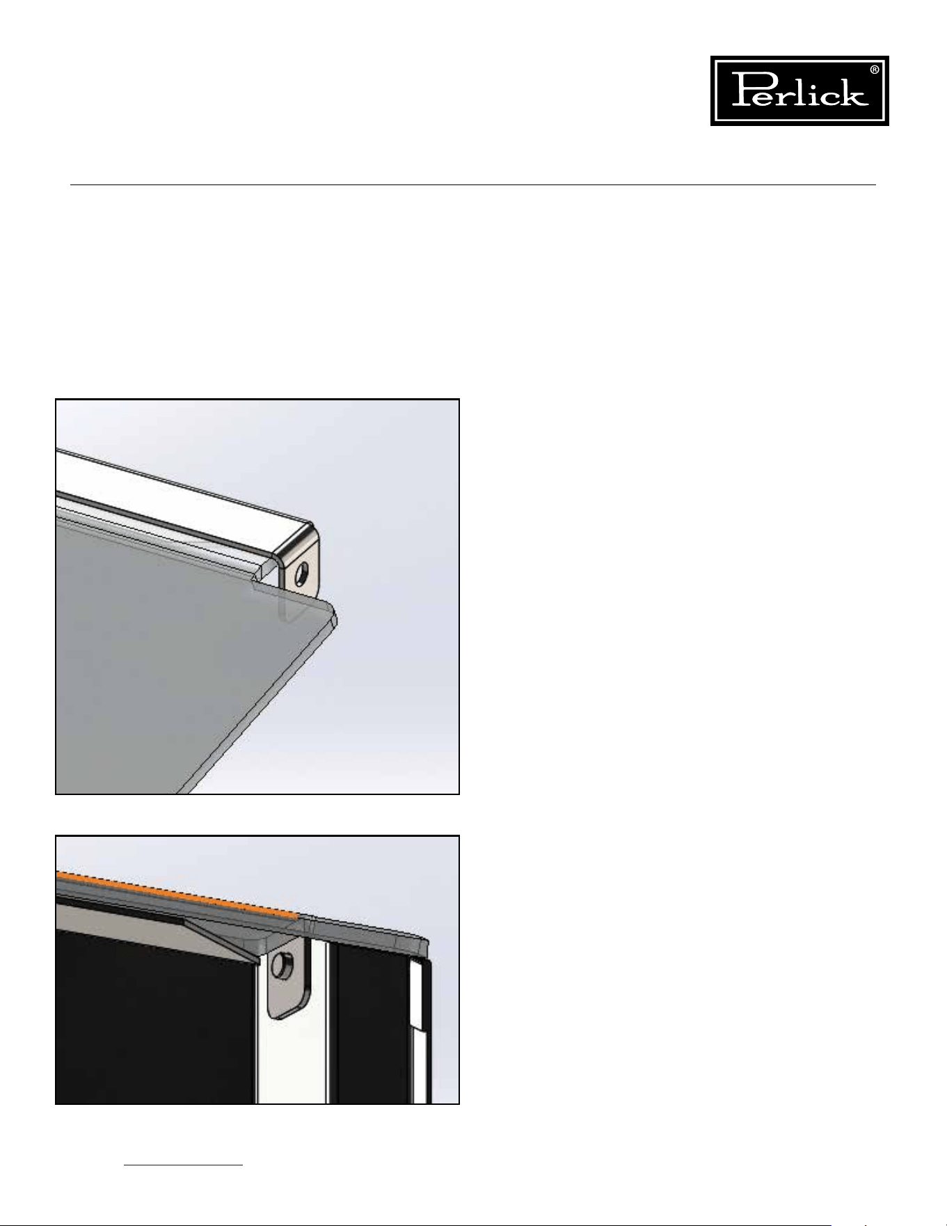
Column Refrigeration Service Manual
Return to Table of Contents
115
8.21 Butter Bin
Toremovebutterbinlid,exlidincenterandpull
upwards on one end of lid to disengage lid from
pin.Slideooppositeendpin.
To install butter bin lid, slide one end over pin and
excenterofthelidtoslipoppositelidendover
pin.
Figure 8-24.1. Butter Bin (1)
Figure 8-24.2. Butter Bin (2)
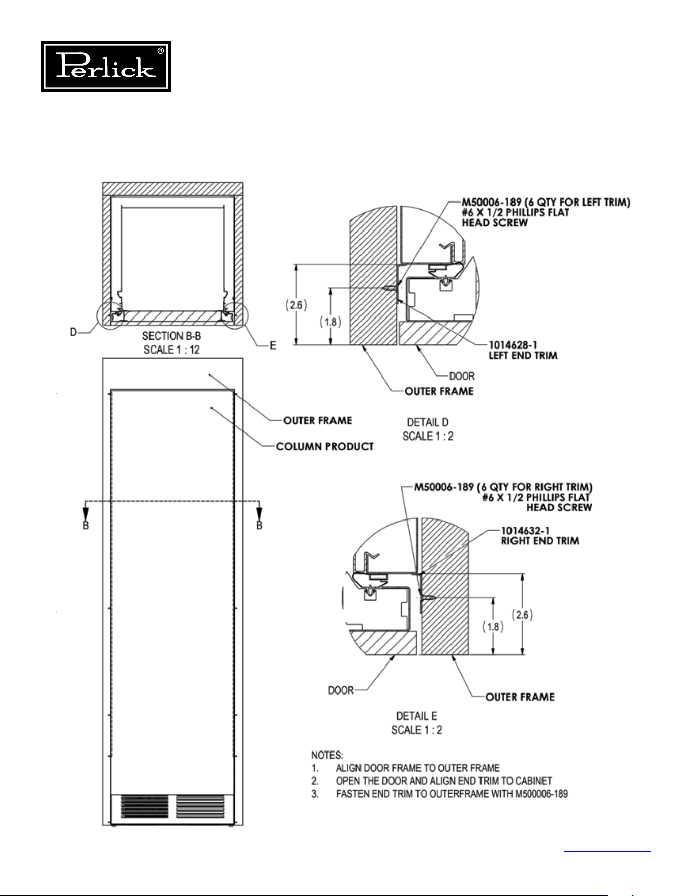
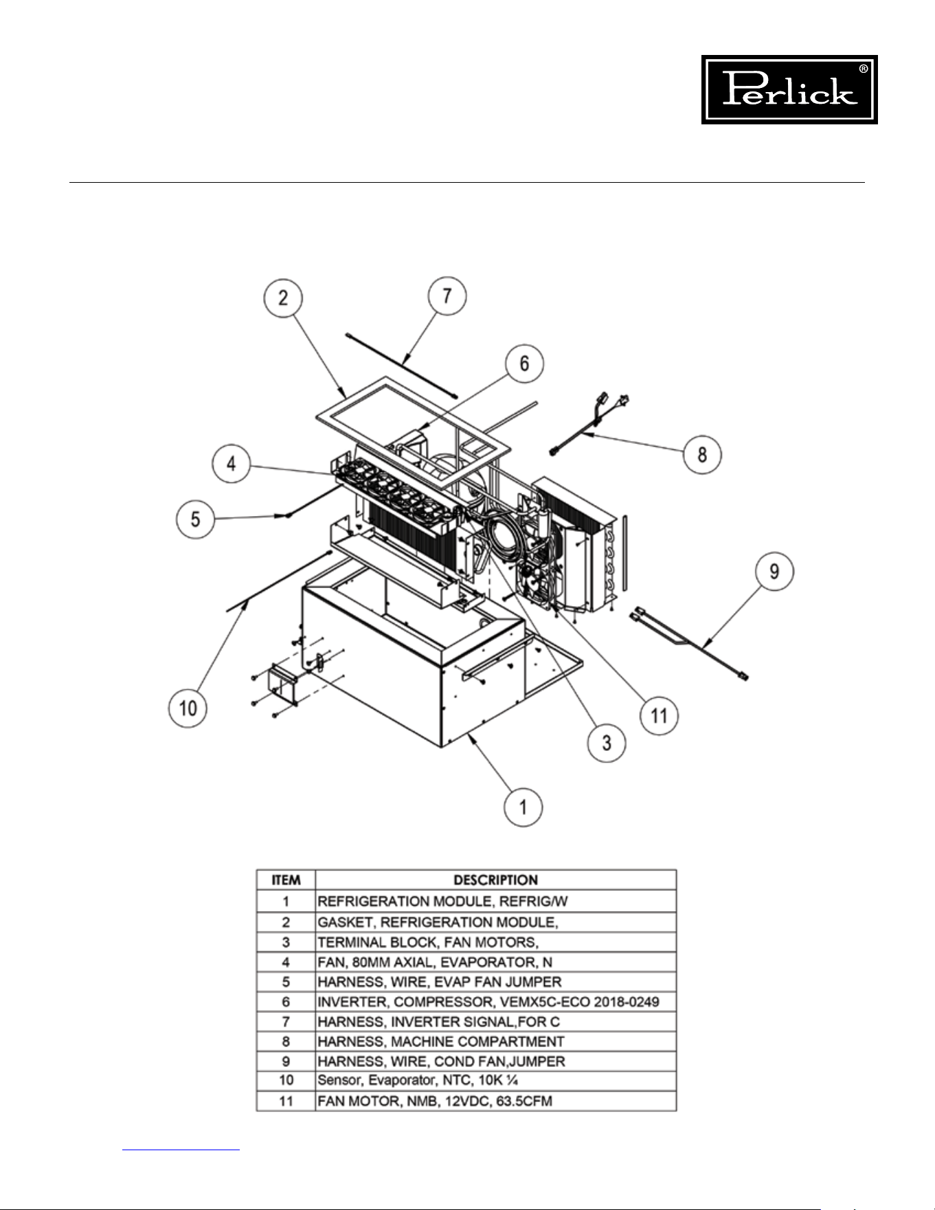
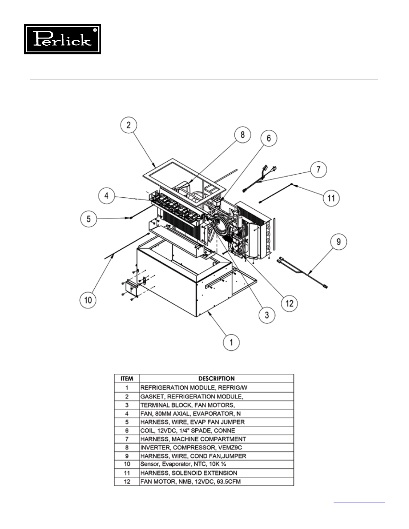
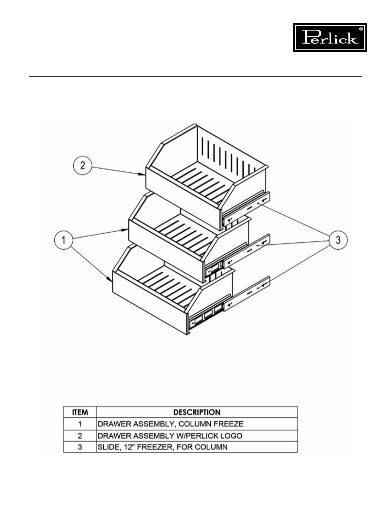
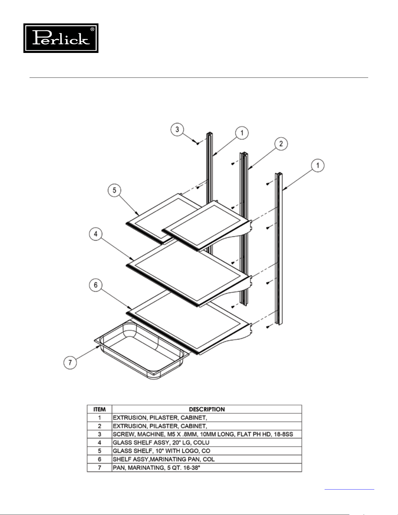
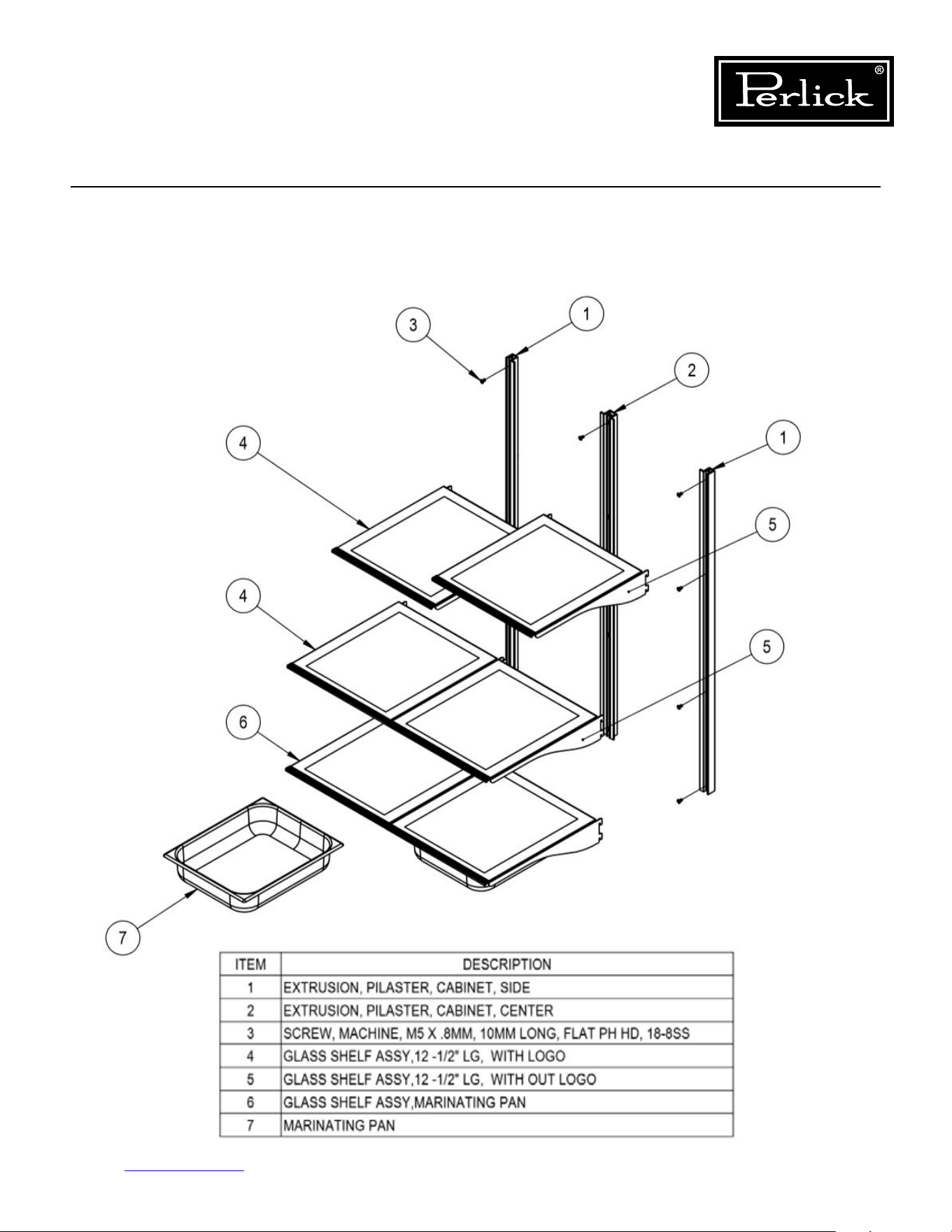
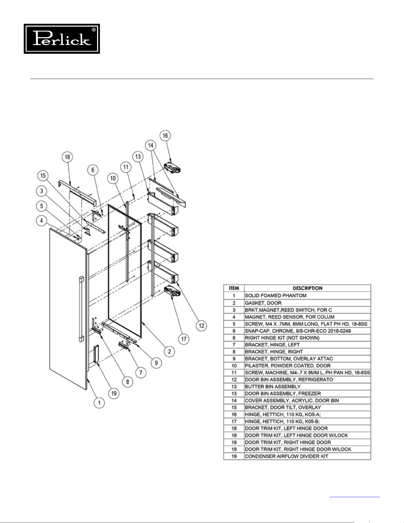
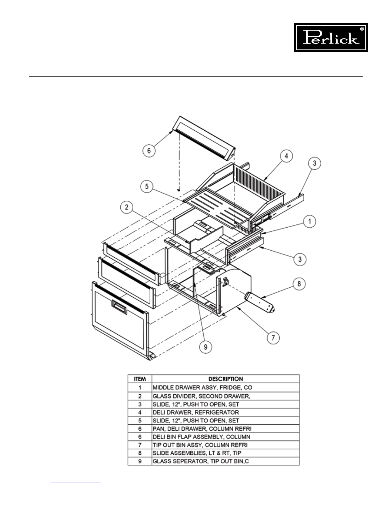
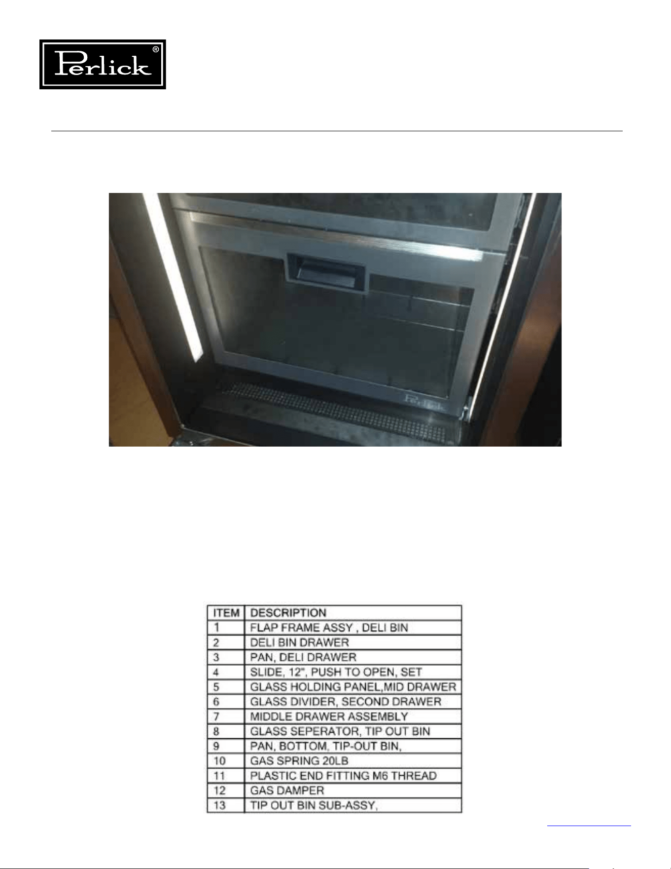
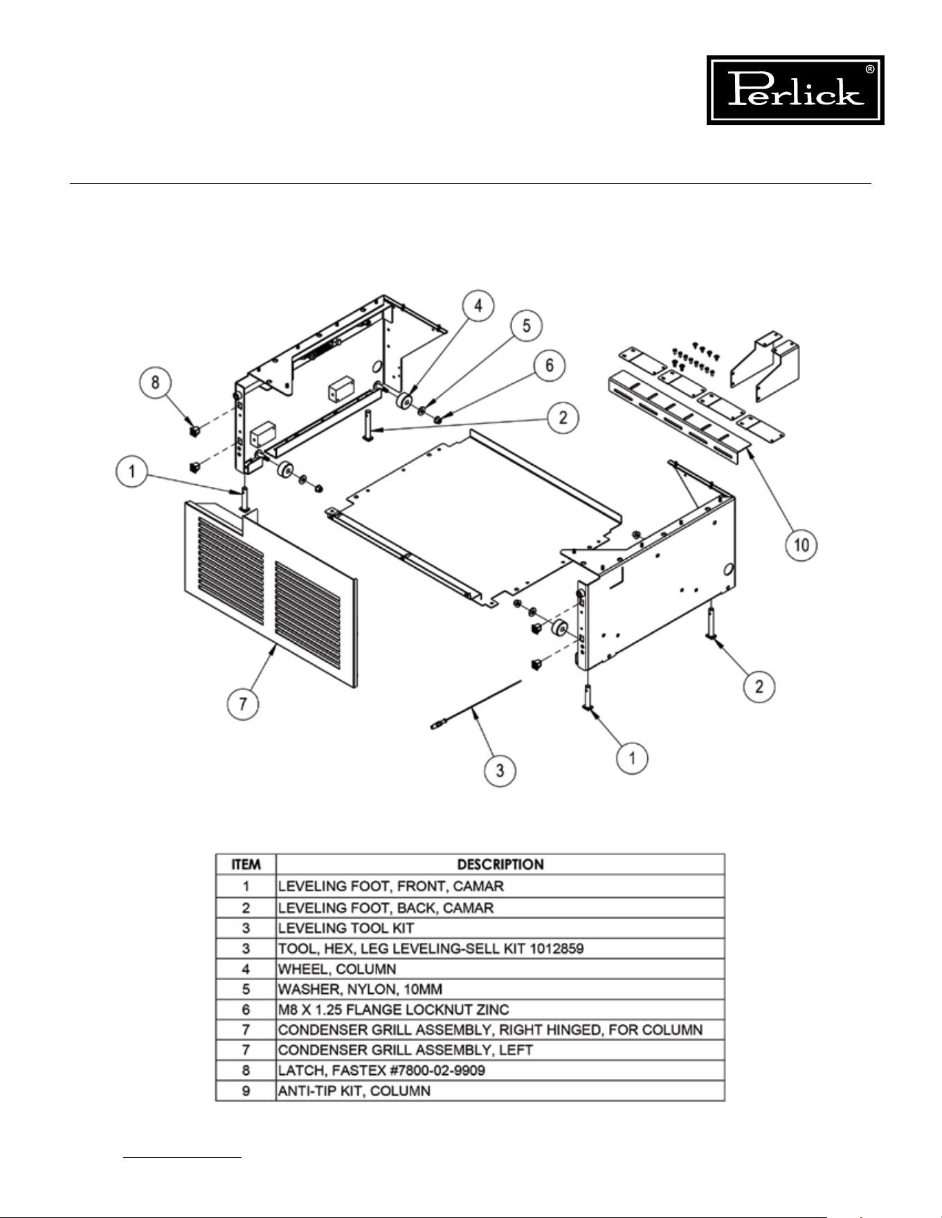
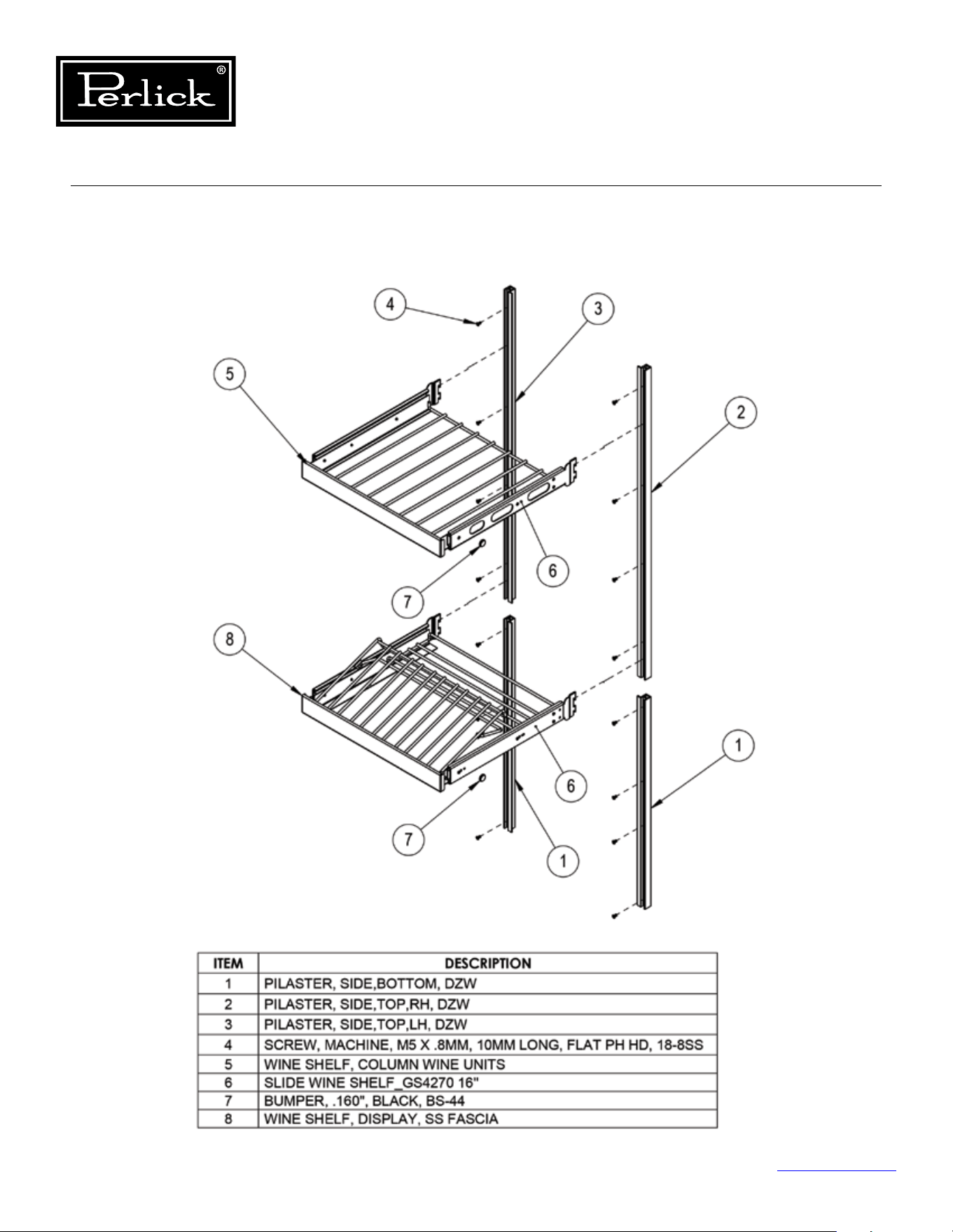
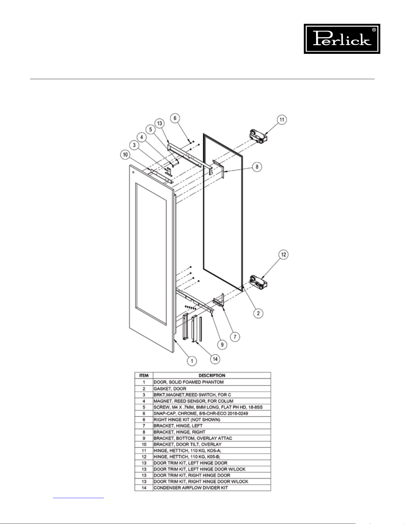
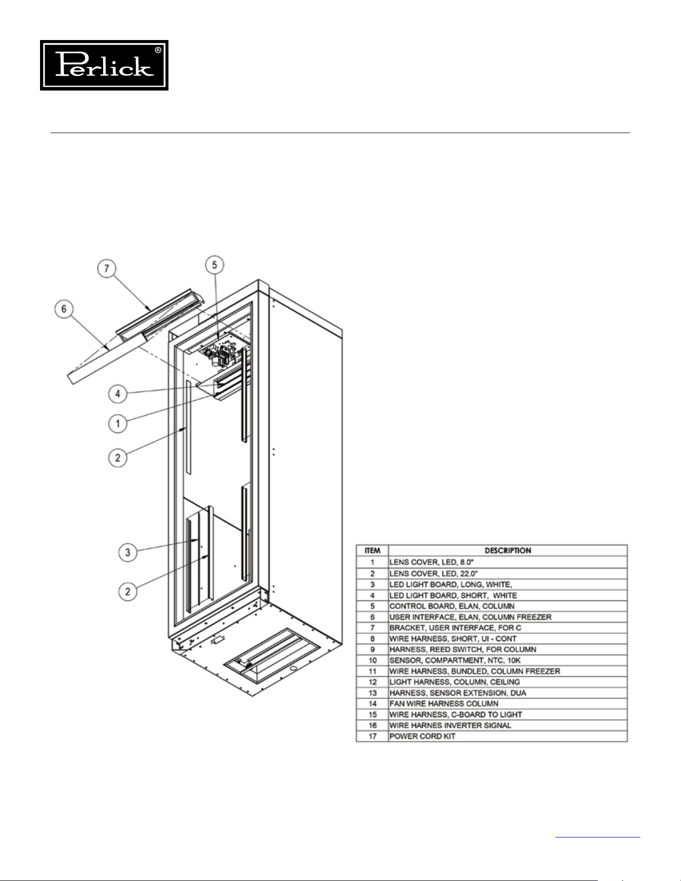
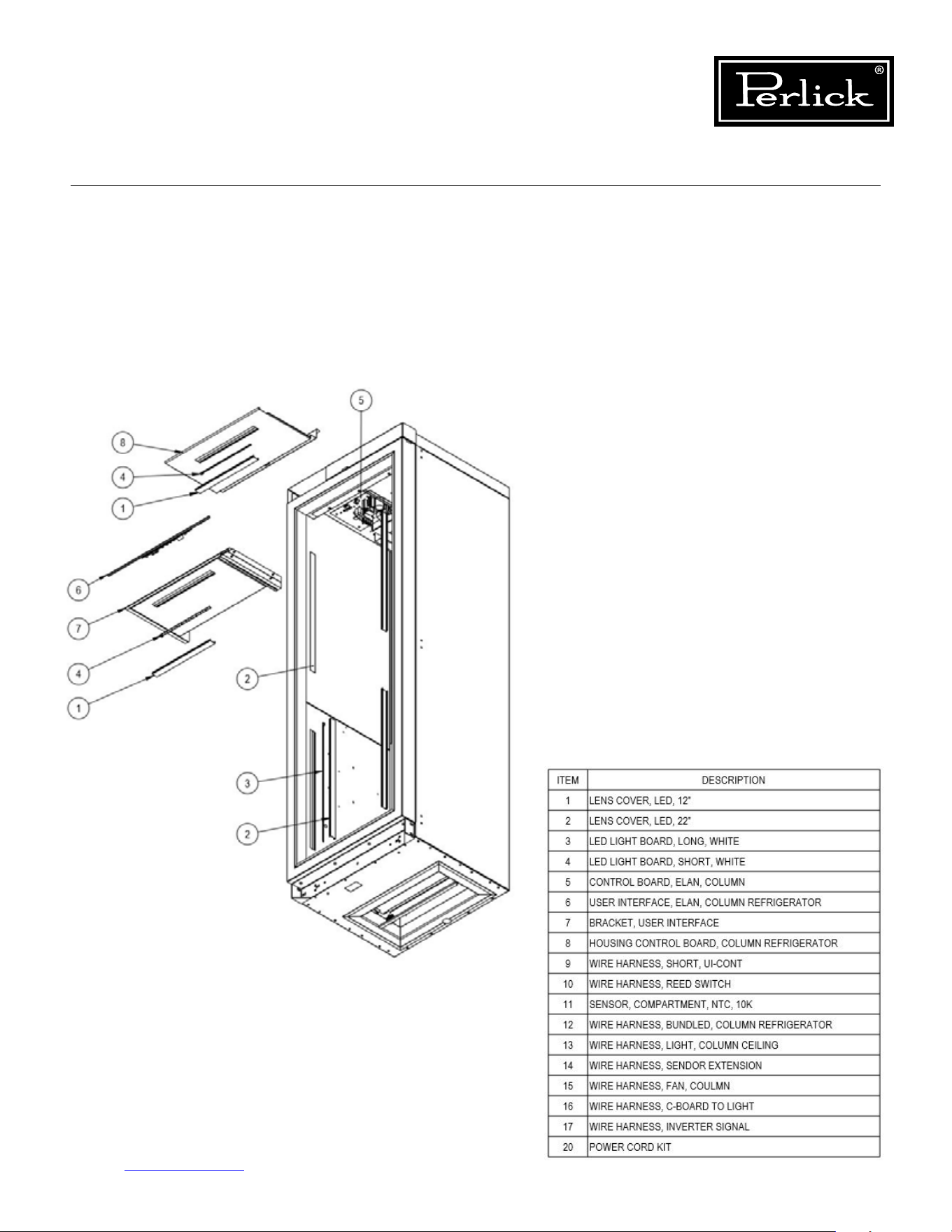
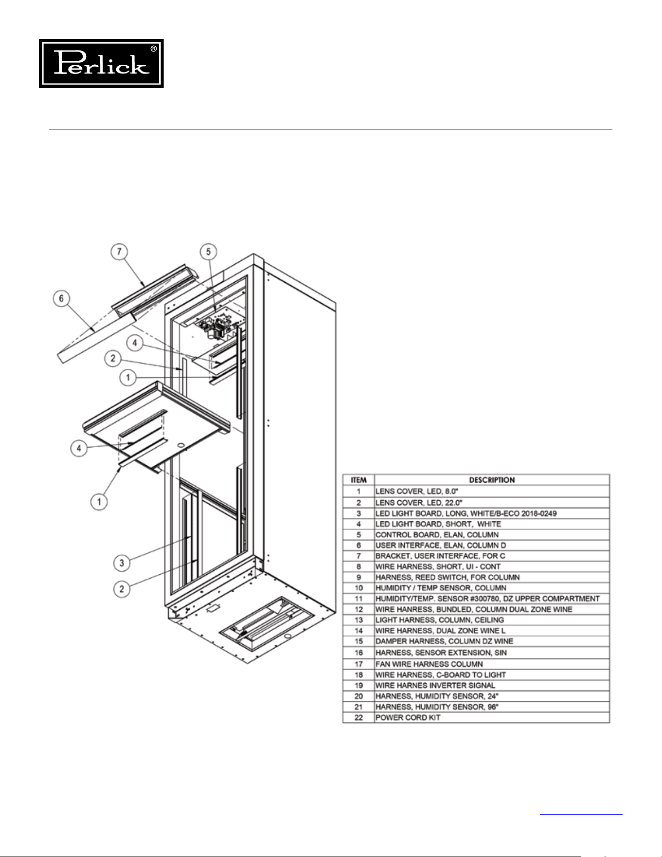
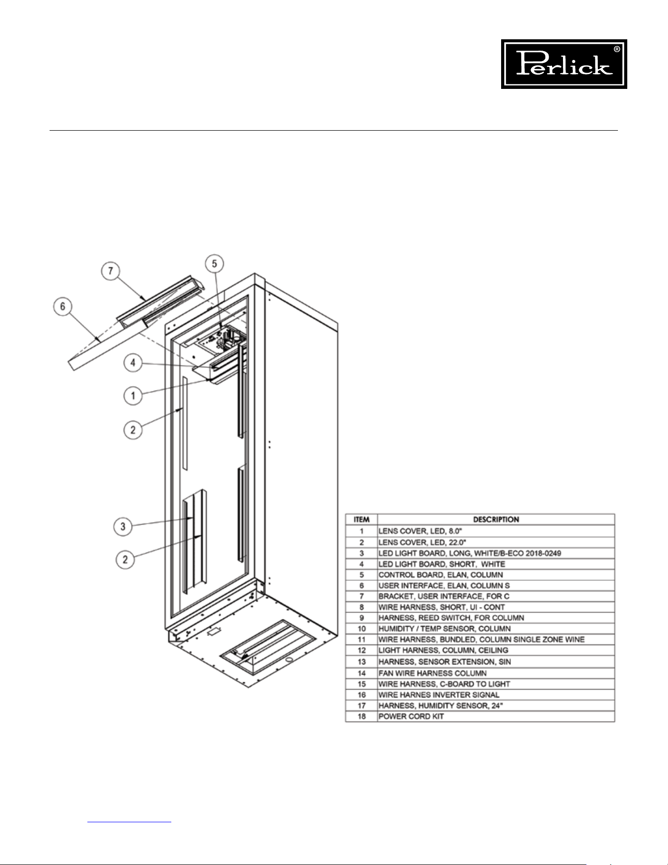
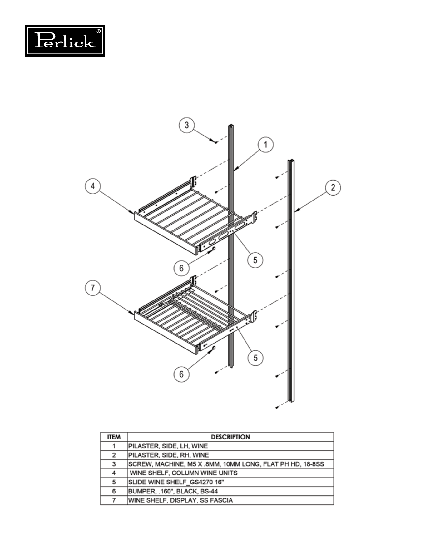

8300 West Good Hope Road • Milwaukee, WI 53223
Toll Free 800.558.5592
• Fax 414.353.7069 • www.perlick.com
Form No. Z2551
Rev. C: 05/03/2019