
REVISED BULLETIN DATE
SERVICE PARTS LIST
BULLETIN NO.
WIRING INSTRUCTION
SERIAL
NUMBER
MILWAUKEE ELECTRIC TOOL CORPORATION
13135 W. LISBON RD., BROOKFIELD, WI 53005
Drwg. 3
SPECIFY CATALOG NO. AND SERIAL NO. WHEN ORDERING PARTS
CATALOG NO.
00
EXAMPLE:
Component Parts (Small #)
Are Included When Ordering
The Assembly (Large #).
0
58-01-0715
Apr. 2010
54-37-0151
5619-20/5619-29
1-3/4 H.P. D-HANDLE ROUTER
280B
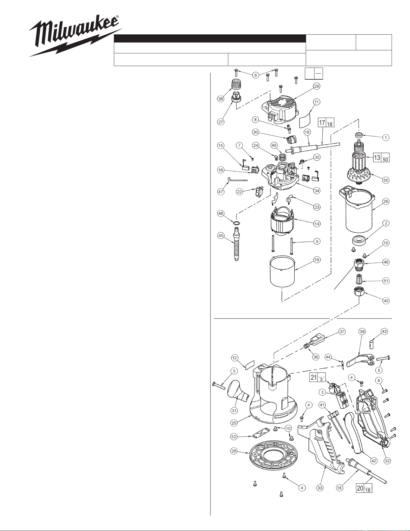
FIG. PART NO. DESCRIPTION OF PART QTY.
1 02-04-0852 Ball Bearing (1)
2 02-04-2006 Ball Bearing (1)
3 05-78-0305 M5.5 x .6 x 7mm Pan Hd. Slt. T-15 (4)
4 06-82-5314 10-24 x 1/2" Slt. Pan Hd. Tapt. T-25 (5)
5 06-82-5514 1/4-20 x 1-1/2" Pan Hd. Slt. Tapt. T-30 (2)
6 06-82-5574 10-24 x 7/8" Pan Hd. Slt. Tapt. T-25 (5)
7 06-82-7212 4-20 x 1/4" Pan Hd. Slt. Plast. T-10 (2)
8 06-82-7270 8-16 x 5/8" Pan Hd. Slt. Plast. T-20 (7)
9 06-82-7455 8-16 x 2-3/8" Pan Hd. Slt. Plast. T-20 (2)
10 06-82-8865 10-32 x 7/16" Pan Hd. Tapt. Sems T-25 (4)
11 12-20-0205 Service Nameplate Kit (1)
12 12-25-0335 Nameplate (1)
13 16-30-0011 Armature (1)
14 18-30-1010 Field (1)
15 22-16-0410 Carbon Brush (2)
16 22-22-0165 Brush Tube (2)
17 22-64-0815 Cord Set Assembly (1)
18 44-76-0210 Cord Protector (2)
19 23-16-0405 Field Insulator (1)
20 22-64-0820 Cord Set Assembly (1)
21 23-66-0168 Switch Assembly (1)
22 23-66-2280 Rocker Switch (1)
23 23-74-0025 Field Terminal (2)
24 23-74-0055 Connector Terminal (1)
25 26-06-0100 Base (1)
26 28-50-0105 Motor Housing (1)
27 31-01-0025 Depth Scale (1)
28 49-54-1045 Sub Base (1)
29 31-15-0065 Motor Cover (1)
30 31-17-0070 Cord Clamp (1)
31 31-44-0130 Knob Handle (1)
32 31-44-0140 Right Handle Halve (1)
33 31-44-0145 Left Handle Halve (1)
34 31-50-0106 Motor Frame (1)
35 40-50-0190 Brush Spring (2)
36 40-50-4005 Compression Spring (1)
37 42-42-0126 Release Button (1)
38 43-98-0531 Depth Knob (1)
39 44-10-0435 Base Clamp Lever (1)
40 44-40-0095 Collet Nut (2 supplied with tool) (1)
41 23-33-0065 Receptacle Outlet (1)
42 44-52-0681 Grip (1)
43 44-60-0095 Thru Pin (1)
44 44-66-0035 Wear Plate (1)
45 45-08-0030 Depth Shaft Assembly (1)
46 45-10-0081 Collet Shank
(See reverse side for servicing)
(1)
47 23-94-0040 Leadwire Assembly (1)
48 45-88-0045 Washer (1)
49 45-88-0577 Wave Spring Washer (3)
50 22-84-0380 Fan Assembly (1)
51 48-66-0985 1/4" Collet (1)
51 48-66-1010 1/2" Collet (1)
52 45-12-0015 Dust Shield (1)
49-96-0365 1-1/8" Open End Wrench (Not Shown) (2)
FIG. NOTES:
5,39 Clamping force for the base clamp lever (39) is
adjusted with base clamp screw (5). Tighten the
screw using 10-20 lbs. force to close the lever to
the locked position. Motor unit must be in base
when checking force.
16,34 When servicing the motor frame (34) and the brush
tube (16) has to be removed, replace with a new
brush tube.
25,36,37 To service the release button (37) and the compression
spring (36) a long, thin tool like a fl at blade screwdriver
must be used. From the bottom of the base (25), insert the
screwdriver into the cavity located under the release
button. Press on the button detent to release.
39,43 Apply a thin coat of "L" grease, No. 49-08-4170, to the
pivot surface areas of the base clamp lever (39). Apply a
thin coat of grease to the surface of the thru pin (43).
Router Motor Assembly
Router Base Assembly
See page 2
for collet shank
removal and
installation.
54-37-0150
= Part number change
from previous service
parts list.
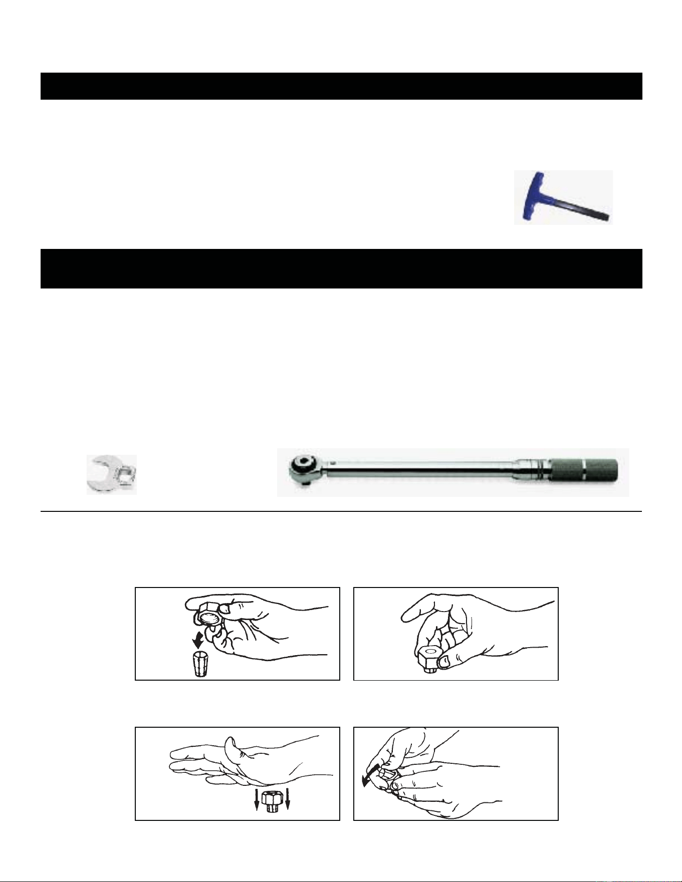
3/8” t-handle Hex Key
ft/lb Torque Wrench
1-1/8”
Crowfoot Wrench
To remove collet from nut, hold nut firmly with one
hand and press the collet to one side with the other
hand (Fig. 4).
Collets
The collet must be attached to the collet nut before it is put into the collet shaft. Be sure that the size of
the collet matches the size of the bit shank being used. If the wrong size bit shank is used, the collet
may break. For attaching or detaching the collet nut to the collet, follow the illustrated instructions.
Attaching Collet to Collet Nut
To assemble, place the narrow end of the collet
on an even surface. Take the nut and place it over
the collet (Fig. 1).
Position nut squarely over collet with the smaller
opening of the nut facing up (Fig. 2).
Snap nut and collet together by firmly applying
downward pressure into assembly with palm of
hand (Fig. 3).
Fig. 2
Fig. 3
Fig. 4
Fig. 1
Repair Instructions for the 5619-20,-29 1-3/4 H.P. D-Handle Router
45-10-0081 Collet Shank – removal / installation
Removal of the Collet Shank from the Armature shaft…
Note: The Armature shaft has a 3/8” internal hex; The Collet Shank threads onto the Armature shaft.
Step 1 applied at the time of assembly, mild heat to the Collet Shank will soften Loctite
®
Threadlocker and will aide in the
disassembly. Care should be taken with a heat gun, not to damage the seal of the Ball Bearing or Contamination Shield.
Step 2 to hold the Armature securely from turning, pass a 3/8” t-handle Hex Key through
the Collet Shank and into the Armature’s 3/8” internal hex.
Step 3 using the Router’s standard equipment Forged 1-1/8” Open End Wrench on the
external hex of the Collet Shank, turn the Collet Shank counter-clockwise 4 to remove.
Installation of the Collet Shank to the Armature shaft…
torque specification of the Collet shank to the Armature shaft is 16.5 ft-lbs [vigorously hand-tight]...
Installation of the Collet Shank [45-10-0081] for a 5619-20,-29 Router can best be accomplished by using a
3/8” t-handle Hex Key, a 1-1/8” Crowfoot Wrench and a Torque Wrench.
Step 1 apply two drops of Loctite
®
‘Blue’ 242
®
or 243 Oil Tolerant, Threadlocker or equivalent, 180° apart, to threads of the
Armature shaft before threading the Collect Shank onto the Armature... care should be taken not to get tread locking
sealant on the ball bearing journal of the Armature shaft.
Step 2 pass a 3/8” t-handle Hex Key through the Collect Shank and into the Armature’s 3/8” internal hex to hold the Armature
securely from turning.
Step 3 using a 1-1/8” Crowfoot Wrench and a Torque Wrench combination turn the 1-1/8” hex of the Collet Shank in a clockwise
3 direction until tight and the specified minimum of 16.5 ft-lbs of torque is reached.