52384.0001 J 12/24 © 2016 - 2024 Bunn-O-Matic Corporation
Bunn-O-Matic Corporation
Post Office Box 3227, Springfield, Illinois 62708-3227
Phone (217) 529-6601 | Fax (217) 529-6644
www.bunn.com
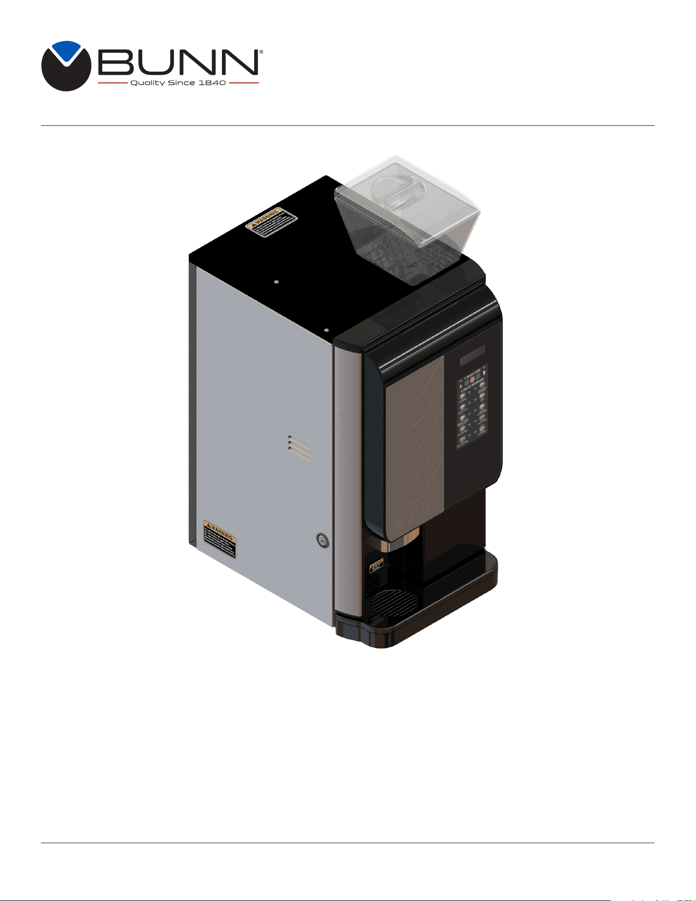
INSTALLATION & OPERATING GUIDE
Crescendo
®
Bean to Cup Espresso System
For Technical Service, contact Bunn-O-Matic Corporation at 1-800-286-6070.

2
Bunn-O-Matic Corp. (“BUNN”) warrants the BUNN Crescendo
®
as further described below for a warranty period of 1
year parts and labor.
For customers subscribed to BUNNlink
®
, BUNN reserves the right to periodically auto-push critical software updates
that will enhance functionality or performance of the BUNN equipment, unless the customer requests advance notice
of such software updates from BUNN in writing.
These warranty periods run from the date of installation. BUNN warrants that the equipment manufactured by it will
be commercially free of defects in material and workmanship existing at the time of manufacture and appearing within
the applicable warranty period. This warranty does not apply to any equipment, component or part that was not manu-
factured by BUNN or that, in BUNN’s judgment, has been affected by misuse, neglect, alteration, improper installation
or operation, improper maintenance or repair, non periodic cleaning and descaling, equipment failures related to poor
water quality, damage or casualty. This warranty is conditioned on the Buyer 1) giving BUNN prompt notice of any claim
to be made under this warranty by telephone at (217) 529-6601 or by writing to Post Office Box 3227, Springfield,
Illinois 62708-3227; 2) if requested by BUNN, shipping the defective equipment prepaid to an authorized BUNN service
location; and 3) receiving prior authorization from BUNN that the defective equipment is under warranty. Additionally, the
following is excluded from the warranty period:
Warranty Exclusions:
• Parts such as, but not limited to, hoppers and lids, drip trays, and plastic parts damaged due to improper handling
or cleaning agents.
• Replacement of wear items such as, but not limited to, O-rings, gaskets, silicone tubes, hoses, and valve seats.
• Repairs made necessary due to poor water quality such as dispense valves, water inlet valves, scaling in the
steam or hot water boilers. (Total Hardness recommended range of 4-7 gpg constant).
• Improper voltage. (See equipment operations manual for voltage specifications).
• Failure to use BUNN approved cleaning supplies constitutes improper maintenance.
• Failure to have required preventive maintenance performed by BUNN technician or authorized espresso
service provider.
• Parts replaced under the terms of this warranty carry the remainder on the machine’s parts warranty term, or 60
days, whichever is greater.
• Drink quality issues from machine failures related to product formulation or product characteristics.
THE FOREGOING WARRANTY IS EXCLUSIVE AND IS IN LIEU OF ANY OTHER WARRANTY, WRITTEN OR
ORAL, EXPRESS OR IMPLIED, INCLUDING, BUT NOT LIMITED TO, ANY IMPLIED WARRANTY OF EITHER
MERCHANTABILITY OR FITNESS FOR A PARTICULAR PURPOSE.The agents, dealers or employees of BUNN
are not authorized to make modifications to this warranty or to make additional warranties that are binding on BUNN.
Accordingly, statements by such individuals, whether oral or written, do not constitute warranties and should not be
relied upon. If BUNN determines in its sole discretion that the equipment does not conform to the warranty, BUNN, at
its exclusive option while the equipment is under warranty, shall either 1) provide at no charge replacement parts and/
or labor (during the applicable parts and labor warranty periods specified above) to repair the defective components,
provided that this repair is done by a BUNN Authorized Service Representative; or 2) shall replace the equipment or
refund the purchase price for the equipment.
THE BUYER’S REMEDY AGAINST BUNN FOR THE BREACH OF ANY OBLIGATION ARISING OUT OF THE
SALE OF THIS EQUIPMENT, WHETHER DERIVED FROM WARRANTY OR OTHERWISE, SHALL BE LIMITED, AT
BUNN’S SOLE OPTION AS SPECIFIED HEREIN, TO REPAIR, REPLACEMENT OR REFUND.
In no event shall BUNN be liable for any other damage or loss, including, but not limited to, lost profits, lost sales, loss
of use of equipment, claims of Buyer’s customers, cost of capital, cost of down time, cost of substitute equipment,
facilities or services, or any other special, incidental or consequential damages.
BUNN-O-MATIC COMMERCIAL PRODUCT WARRANTY

3
TIP: For advanced programming information go to www.bunn.com to obtain the latest information.
CONTENTS
WARRANTY ...............................................................................................................................2
NORTH AMERICAN AND CE REQUIREMENTS ......................................................................4
USER NOTICES ......................................................................................................................... 5
INITIAL SETUP
Drip Tray, Brew Group and Bean Hopper ..............................................................................5
Filling Soluble Hoppers .........................................................................................................6
Capacity ................................................................................................................................ 8
Electrical Requirements ........................................................................................................ 8
Calibration ............................................................................................................................8
PLUMBING REQUIREMENTS
Plumbing Hook-up ................................................................................................................9
Initial Fill & Heat .................................................................................................................... 9
Preset Tank Temperature ......................................................................................................9
Liquid Level Control ..............................................................................................................9
OPERATING CONTROLS AND INTERFACE
Operating The Dispenser .................................................................................................... 10
Modifying The Touch Switch Functions ............................................................................... 11
Creating A “Custom” Beverage ...........................................................................................11
Set Espresso Shots .......................................................................................................11
Recipe Setup .................................................................................................................12
Touchless Sensitivity Selection Options .............................................................................14
Confirm Beverage Screens .................................................................................................15
DOOR SAFETY INTERLOCK ..................................................................................................16
THROUGH COUNTER OPTION
Countertop and Machine Modifications ..............................................................................16
Software Setup ...................................................................................................................16
ENERGY SAVER MODE ..........................................................................................................17
GENERAL CLEANING .............................................................................................................18
CLEANING
Daily .................................................................................................................................... 20
Weekly
Rinse Cycle .....................................................................................................................21
Whipper Components .....................................................................................................23
Hopper Components .......................................................................................................24
BI-Weekly
Brew Chamber ...............................................................................................................25
PREVENTIVE MAINTENANCE ................................................................................................ 28
ADJUSTMENTS .......................................................................................................................29
DRAINING THE HOT WATER TANKS ......................................................................................31
WIRING SCHEMATIC ..............................................................................................................32

4
• This appliance must be installed in locations where it can be overseen by trained personnel.
• For proper operation, this appliance must be installed where the temperature is between 41°F to 95°F
(5°C to 35°C).
• Appliance shall not be tilted more than 10° for safe operation.
• An electrician must provide electrical service as specified in conformance with all local and national codes.
• This appliance must not be cleaned by pressure washer.
• This appliance can be used by persons if they have been given supervision or instruction concerning use
of the appliance in a safe way and if they understand the hazards involved.
• Keep the appliance and its cord out of reach of children.
• Appliances can be used by persons with reduced physical, sensory or mental capabilities or lack of
experience and knowledge if they have been given supervision or instruction concerning use of the
appliance in a safe way and understand the hazards involved.
• If the power cord is ever damaged, it must be replaced by the manufacturer or authorized service
personnel with a special cord available from the manufacturer or its authorized service personnel in
order to avoid a hazard.
• Machine must not be immersed for cleaning.
• This appliance is intended for commercial use in applications such as:
– staff kitchen areas in shops, offices and other working environments
– by clients in hotel and motel lobbies and other similar types of environments
• Access to the service areas permitted by Authorized Service personnel only.
NORTH AMERICAN REQUIREMENTS
• This appliance must be installed in locations where it can be overseen by trained personnel.
• For proper operation, this appliance must be installed where the temperature is between 5°C to 35°C.
• Appliance shall not be tilted more than 10° for safe operation.
• An electrician must provide electrical service as specified in conformance with all local and national codes.
• This appliance must not be cleaned by water jet.
• This appliance is not intended for use by persons (including children) with reduced physical, sensory
or mental capabilities, or lack of experience and knowledge, unless they have been given instructions
concerning use of this appliance by a person responsible for its safety.
• This appliance is intended to be used for commercial applications, for example in kitchens of restaurants,
canteens, hospitals and in commercial enterprises such as bakeries, butcheries, etc., but not for continuous
mass production of food.
• Children should be supervised to ensure they do not play with the appliance.
• If the power cord is ever damaged, it must be replaced by the manufacturer or authorized service
personnel with a special cord available from the manufacturer or its authorized service personnel in
order to avoid a hazard.
• Machine must not be immersed for cleaning.
• Machine rated IX P1.
CE REQUIREMENTS
5
3
INITIAL SETUP
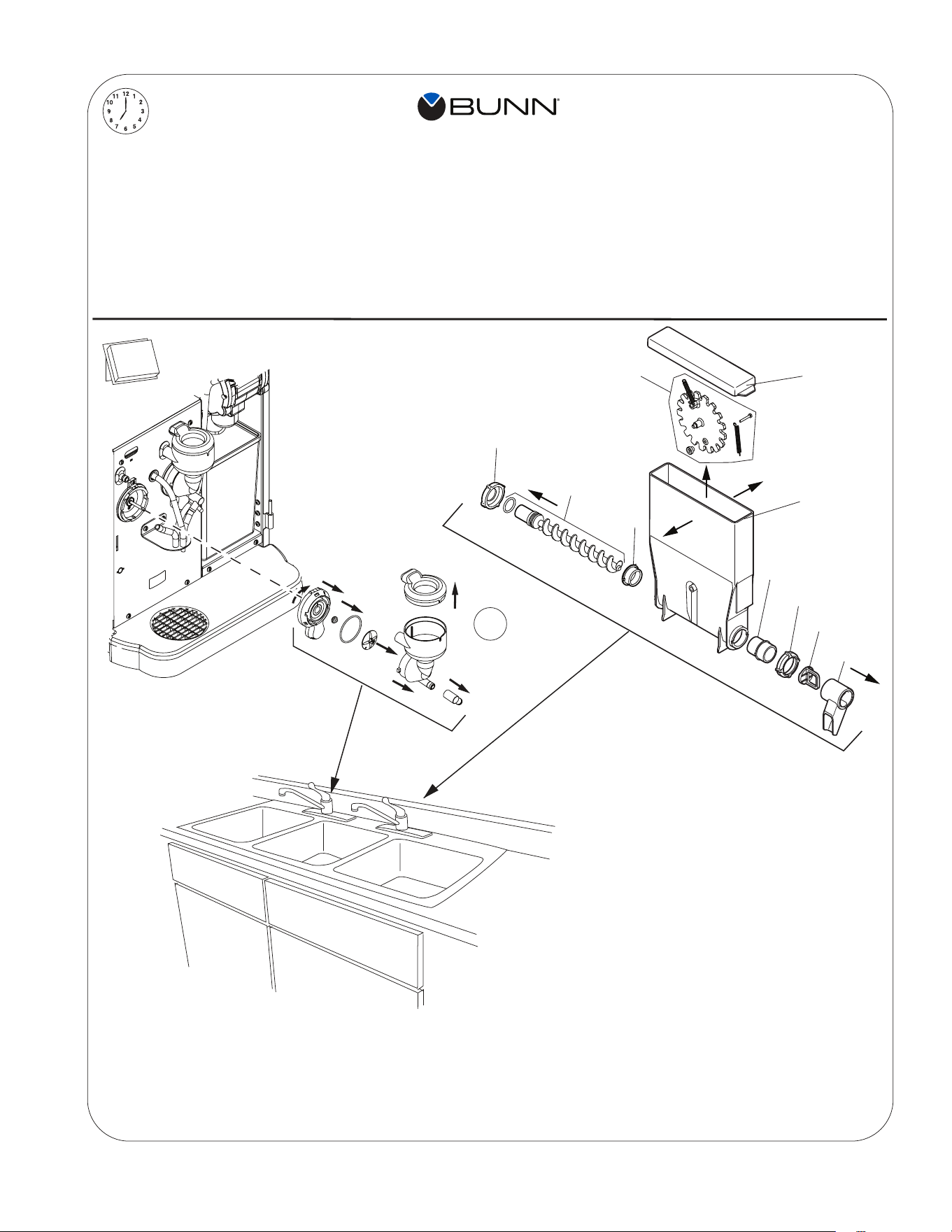
1. Remove drip tray and cover from the parts box. Attach
the cover to the drip tray, then slide under the front door
of the machine, engaging the rear of the drip tray into
the opening in the lower front of the machine.
3. Remove the espresso brew group from the parts box.
The notices on this dispenser should be kept in good condition. Replace unreadable or damaged labels.
00824.0002
00986.0000
WARNING
FAILURE TO COMPLY RISKS EQUIPMENT
DAMAGE, FIRE OR SHOCK HAZARD.
READ THE ENTIRE
OPERATING MANUAL BEFORE
USING THIS PRODUCT
00986.0000M 10/14 ©1994 Bunn-O-Matic Corporation
Use only on a properly protected
circuit capable of the rated load.
Electrically ground the chassis.
Follow national/local electrical codes.
Do not use near combustibles.
Do not deform plug or cord.
37881.0000
To reduce the risk of electric shock,
do not remove or open cover.
No user-serviceable parts inside.
Authorized service personnel only.
Disconnect power before servicing.
WARNING
00656.0001
As directed in the International Plumbing Code of the
International Code Council and the Food Code
Manual of the Food and Drug Administration (FDA),
this equipment must be installed with adequate
backflow prevention to comply with federal, state
and local codes. For models installed outside the
U.S.A., you must comply with the applicable Plumbing
/Sanitation Code for your area.
WARNING
12368.0002
USER NOTICES
continued >
4
5
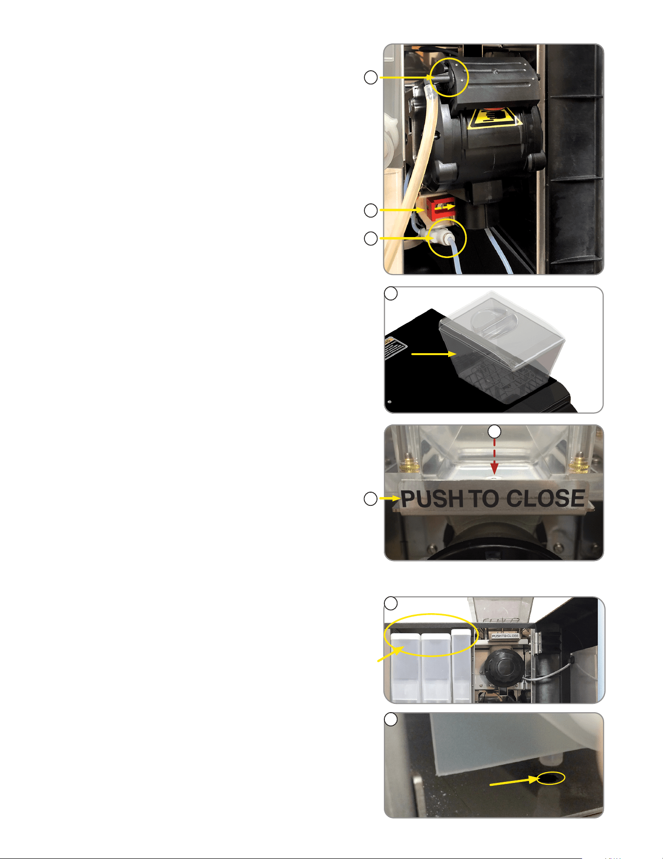
4. Place groove on lower front of brew chamber onto
mounting bar on espresso drive.
5. Rotate the top of group head toward rear of machine
until it snaps into place.
1
DRIP TRAY, BREW GROUP AND BEAN HOPPER
2. Remove keys from the door front.
6
INITIAL SETUP
10. Align the bean hopper so that the collar on the bottom of
the bean hopper will engage the opening in the grinder.
10
11
11. When the hopper is in place on the grinder, pull the
hopper gate all the way forward to allow beans into the
grinder, then lock hopper in place.
1
DRIP TRAY, BREW GROUP AND
BEAN HOPPER (
continued)
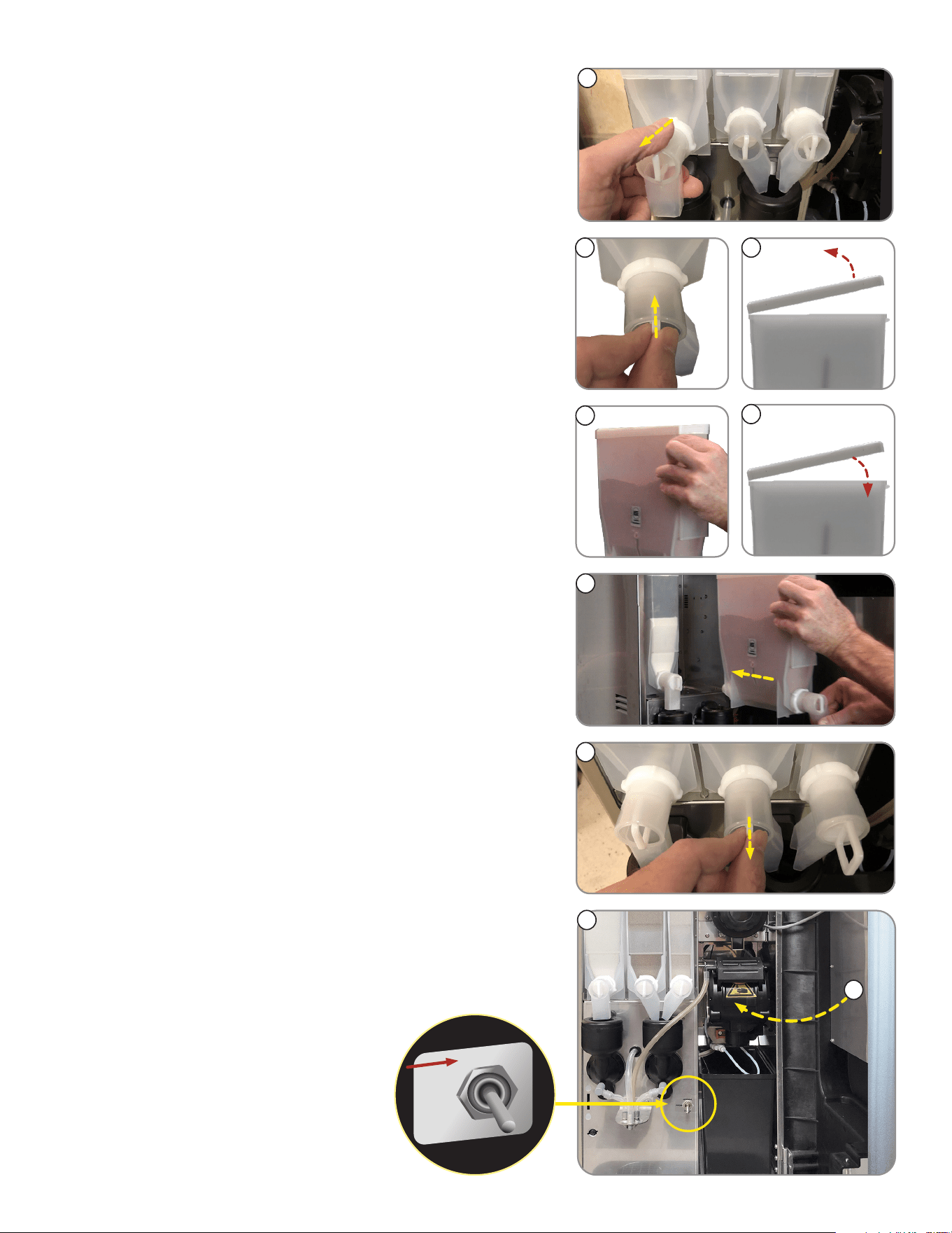
FILLING SOLUBLE HOPPERS
1. Remove packing material from on top of the
powder hoppers.
2. Remove powder hoppers by lifting the front of the powder
hopper until the peg on the bottom of the hopper clears
the hole in the mounting plate.
2
9. Remove the bean hopper from the parts box and install
in top of machine.
9
6. Connect brew chamber outlet tube.
7. Slide red lock to right until it locks.
8. Connect water inlet tube.
6
7
8
7
INITIAL SETUP
4
10. Once everything is installed, Place the NORMAL/
PROGRAM/RINSE switch in the NORMAL position.
11. Close door.
9
6
8
NORMAL
PRGM
RINSE
8. Reinstall hoppers into machine.
NOTE: Make sure peg on bottom of hopper drops into
locating hole on hopper platform.
9. After hoppers are installed, pull slider gates out so that
powder can pass through to dispense.
FILLING SOLUBLE HOPPERS (continued)
4. Set the hoppers on the counter, and push the slide gates
on the elbows in to close.
5. Remove hopper lids.
3. Pull the hopper forward to remove.
3
5
6. Fill hoppers with appropriate soluble products.
NOTE: Default menu is milk product left hopper, chocolate
is center hopper, and vanilla is right hopper.
7
7. Replace hopper lids.
10
continued >
11
8
INITIAL SETUP
ELECTRICAL REQUIREMENTS
CAUTION: The dispenser must be disconnected from the power source until specified in
Electrical Hook-Up.
Electrical Hook-Up
CAUTION: Improper electrical installation will damage electronic components.
1. An electrician must provide electrical service as specified.
2. Using a voltmeter, check the voltage and color coding of each conductor at the electrical source.
3. Connect the dispenser to the power source.
4. If plumbing is to be hooked up later be sure the dispenser is disconnected from the power source.
If plumbing has been hooked up, the dispenser is ready for Initial Fill & Heat.
CAPACITY
1. Brew chamber has a capacity rating of 5 gm minimum up to 15 gm maximum of espresso grind coffee.
2. Brewer has a peak capacity of 60 single (small) espresso shots per hour.
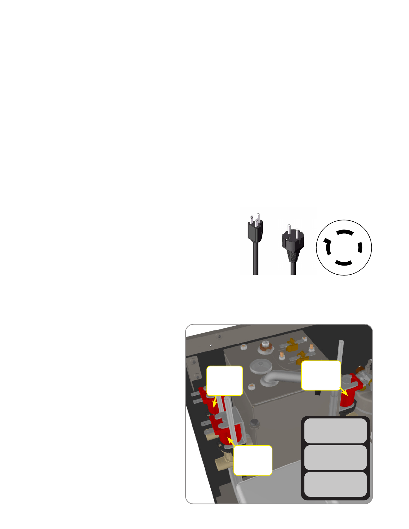
Configuration
120V Configuration:
This electrical service consists of 2 current carrying conductors
(L1 and Neutral) and a separate conductor for chassis ground.
120-208/240V Configuration:
This electrical service consists of 3 current carrying conductors
(L1, L2 and Neutral) and a separate conductor for chassis ground.
220-240V Configuration:
This electrical service consists of 2 current carrying conductors
(L1, L2) and a separate conductor for chassis ground.
120V
Models
220-240V
Models
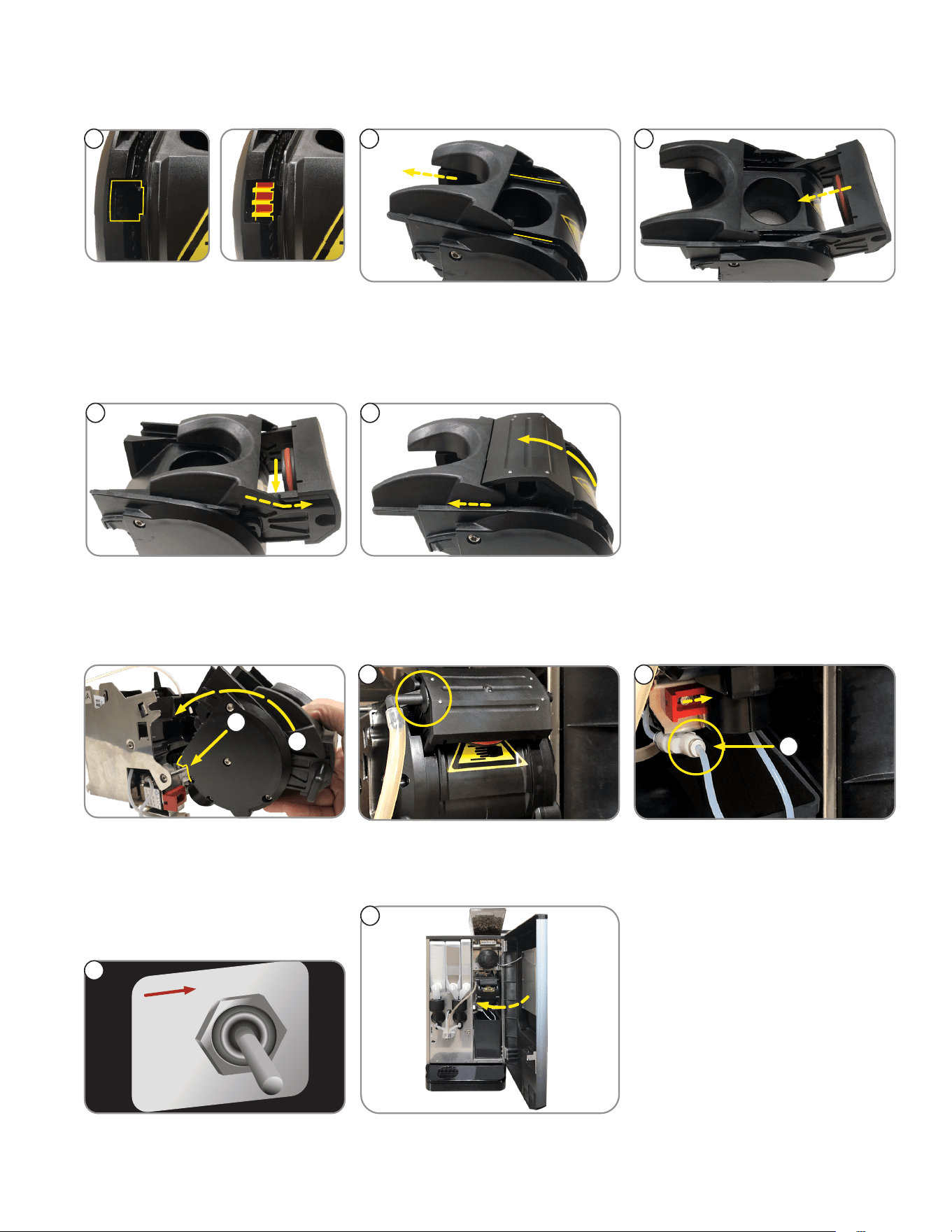
Begin by using an allen wrench to back out
the flow-rate adjuster (counter-clockwise). The
number of turns are shown next to each valve.
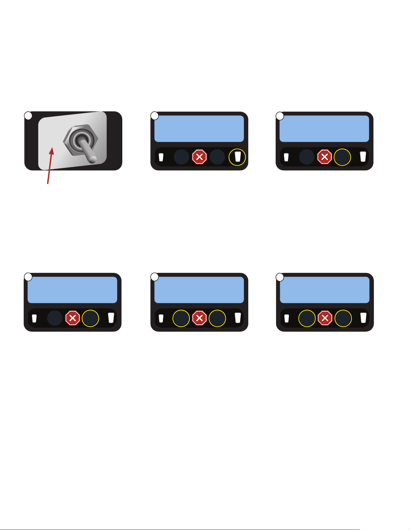
1. Open the door and place the toggle switch
to the “PRGM” setting.
2. Use the large cup size icon to navigate
to the menu to perform a timed dispense
to determine flow-rate for valve(s)
being replaced.
3. Use 6mm allen wrench to increase
(counter-clockwise) or decrease
(clockwise) flow-rate.
Left Soluble
6.6oz - 7.2oz
(198g - 216g)
*2.0 turns
Right Soluble
6.6oz - 7.2oz
(198g - 216g)
*2.0 turns
Hot Water
9.7oz - 10.3oz
(275g - 292g)
*3.25 turns
CALIBRATION PROCEDURE
NOTE: this is only recommended when
a valve is replaced, or when water
dispense volume is not met.
TEST HOT WATER
DISPENSE TO TEST
TEST LFT PWDR VLV
DISPENSE TO TEST
TEST RT PWDR VLV
DISPENSE TO TEST
120-208/240V
Models
X
W
Y
G
9
NOTE: Bunn-O-Matic recommends 6mm copper tubing for installations of less than 25 feet and 8mm for more
than 25 feet from the water supply line. At least 18 inches of an FDA approved flexible beverage tubing, such as
reinforced braided polyethylene or silicone, before the dispenser will facilitate movement to clean the counter top.
Bunn-O-Matic does not recommend the use of a saddle valve to install the dispenser. The size and shape of the hole
made in the supply line by this type of device may restrict water flow.
As directed in the International Plumbing Code of the International Code Council and the Food Code Manual of
the Food and Drug Administration (FDA), this equipment must be installed with adequate backflow prevention to
comply with federal, state and local codes. For models installed outside the U.S.A., you must comply with the
applicable Plumbing /Sanitation Code for your area.
PLUMBING REQUIREMENTS
PRESET TANK TEMPERATURE
The tank temperatures have been preset at the factory to 80°C (180°F) for the soluble tank, and 102°C (215°F) for the
espresso tank. Bunn recommends that to provide the best quality beverage, the installer adjust the tank temperature to the
powder product manufacturers recommended temperature for the hot powder product being used.
1. Fill the hopper(s) with the dry product to be dispensed.
2. Fill the bean hopper with the whole beans to be ground and brewed. A grinder calibration should be performed.
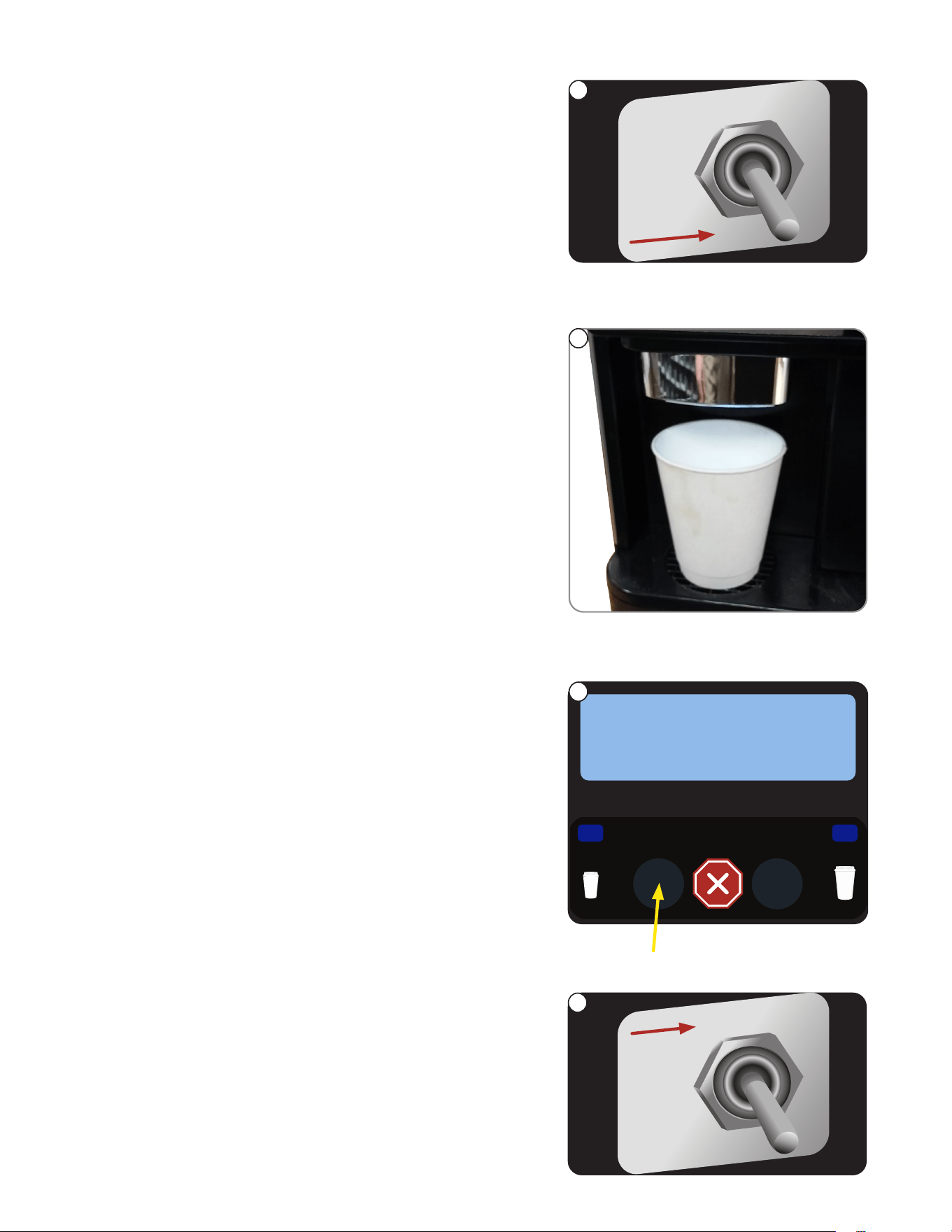
INITIAL FILL & HEAT
1. Turn on the water supply, connect power to the dispenser, and place the main power switch on the rear of the
machine to the ON position.
2. Water will automatically flow into the soluble tank to the proper level, then shut off. This will take less than five
minutes. In the event that a message appears “fill time too long” power cycle to clear the message.
3. The screen on the front door will display FILL ESPRSO TANK. Press the button under START.
4. The screen will display MOVING BREW CHAMBER, ESP TANK FILLING, and the espresso tank will begin filling. This
may take several minutes. In the event that a message appears “fill time too long”, flip the toggle switch to program
mode, then back to normal position to clear the message.
5. When water dispenses from the espresso nozzle into the drip tray, press YES under WATER DISPENSED? to stop
the tank filling.
6. The tanks will then begin heating. When the tanks have completed heating, the display will read “READY TO BREW
SELECT SIZE”.
NOTE: If a backflow preventer is required by code, a shock arrestor should be installed between backflow preventer
and dispenser. Installing the shock arrestor as close to the dispenser as possible will provide the best results.
NOTE: Water pipe connections and fixtures directly connected to a potable water supply shall be sized, installed and
maintained in accordance with federal, state and local codes.
This dispenser must be connected to a cold water system with operating pressure between 138 - .620 MPa (20 and 90 psi)
from a 1⁄2” or larger supply line. A shut-off valve should be installed in the line before the dispenser. Install a regulator
in the line when pressure is greater than .620 MPa (90 psi) to reduce it to .345 MPa (50 psi). The water inlet fitting is
3/4” NPT (US and Canada Models) and 3/4 British Parallel Pipe for all other models.
LIQUID LEVEL CONTROL
The system automatically maintains the soluble hot water tank’s level by energizing the refill solenoid when the water
level drops below the liquid level probe. If the system has not successfully refilled, a refill error occurs. When a refill error
occurs, the refill solenoid is de-energized. Once the cause of the refill error has been investigated and cured, the system
can be reset by either cycling the power to the machine (at least five seconds) using the main power switch at the rear of
the machine, or by entering one of the program modes (see Programming Modes.)
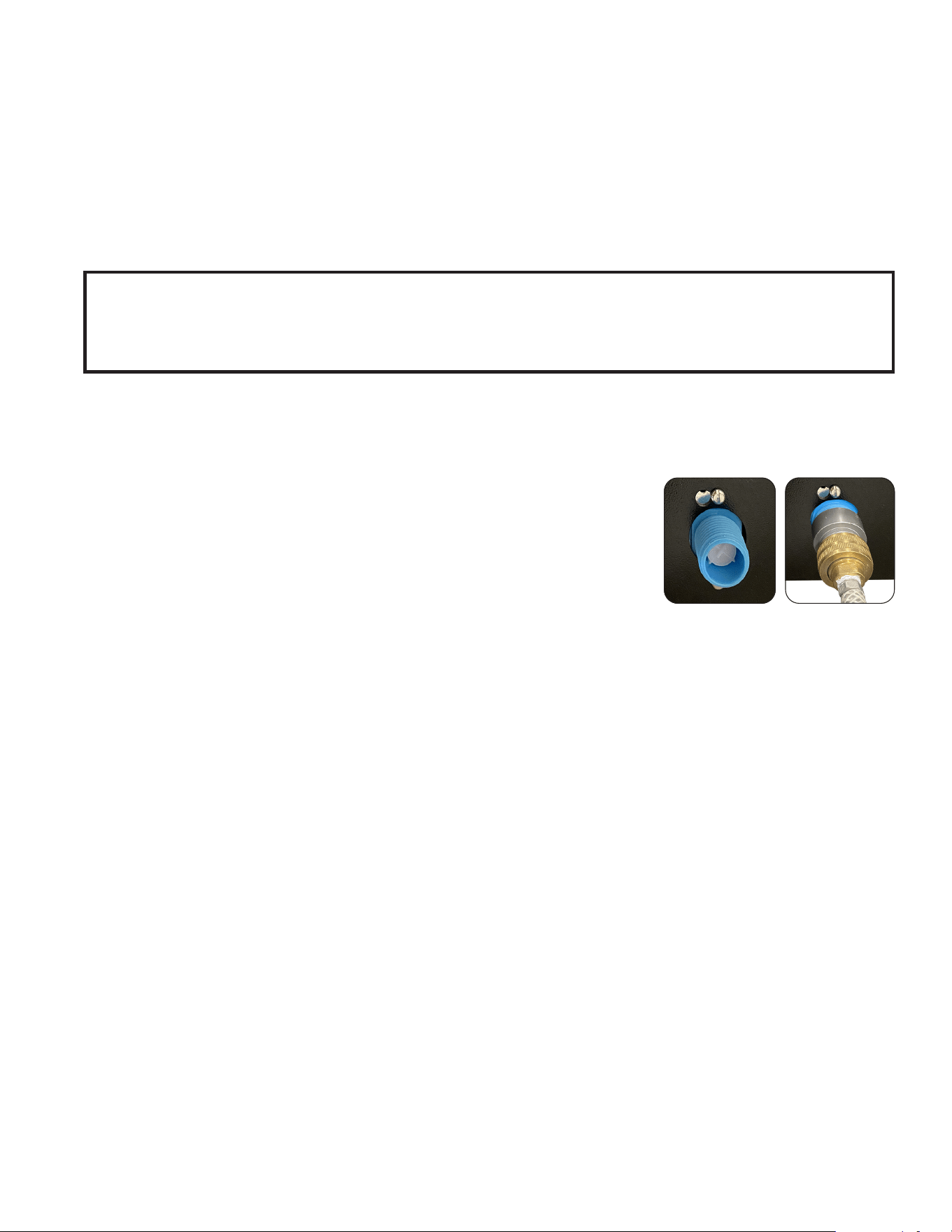
PLUMBING HOOK-UP
NOTE: The plumbing connection is located on the back of the unit, using the water
line included with some models, that connects to a 3/8” male flare or 3/4” hose
thread.
1. Flush the water line and securely attach it to the valve threads on the rear of the dispenser.
2. Turn on the water supply.
10
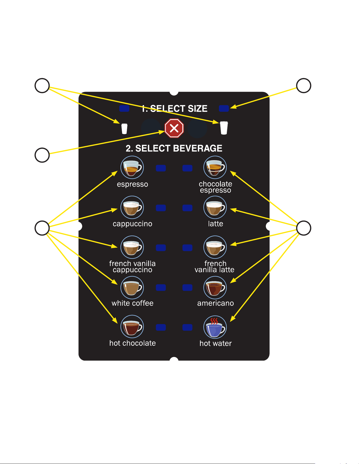
1. Cup Size Buttons: Momentarily pushed to select beverage size to dispense.
2. Dispense Buttons: Momentarily pushed to dispense selected beverage.
3. LED indicators: Illuminates when the adjoining button has been selected.
4. Stop button: Pressing the stop button during dispensing will stop the dispense sequence.
OPERATING THE DISPENSER
NOTE: The NORMAL/PROGRAM/RINSE switch must be in the NORMAL position.
OPERATING CONTROLS AND INTERFACE
1
4
2
3
2
1. Place a cup on the drip tray beneath the dispense nozzle.
2. In the area marked “1” of the control panel:
• Multi-cup only – Select desired beverage size, small or large cup. This selection is mandatory for dispensing.
3. In the area marked “2” of the control panel:
• Press the button to dispense the desired beverage. Dispensing is portion controlled, and will
automatically stop when the correct amount of beverage has been dispensed.
11
Single Cup Mode
When the SINGLE cup size beverage mode is selected, the large and small cup size buttons are disabled.
To dispense a beverage, press only the dispense button of the beverage desired. The option to select which
beverage size is used can be done when creating a custom recipe or espresso dispense. See Crescendo
Programming Manual for more information.
TIP: A display graphic for single cup dispensing is available for purchase from BUNN.
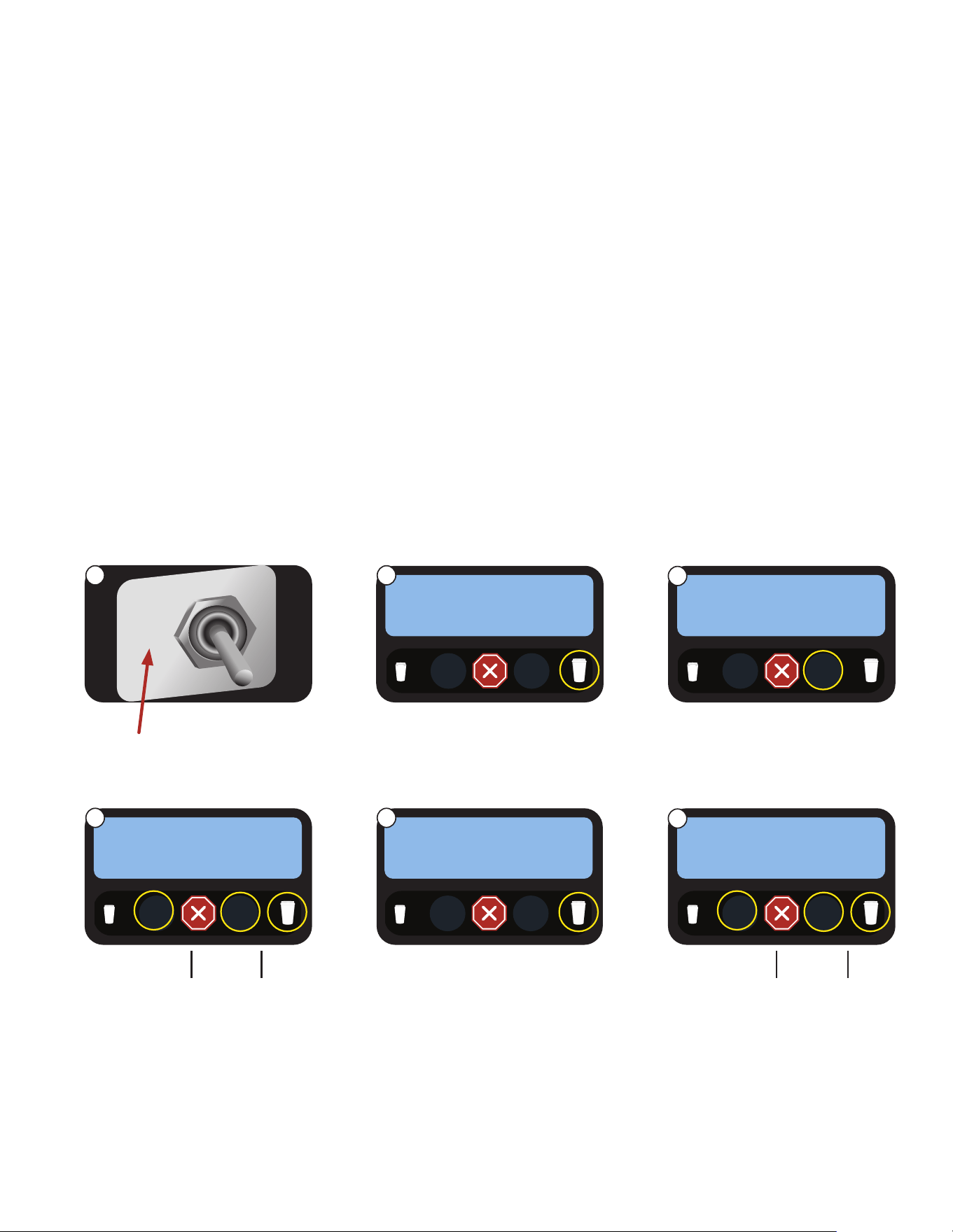
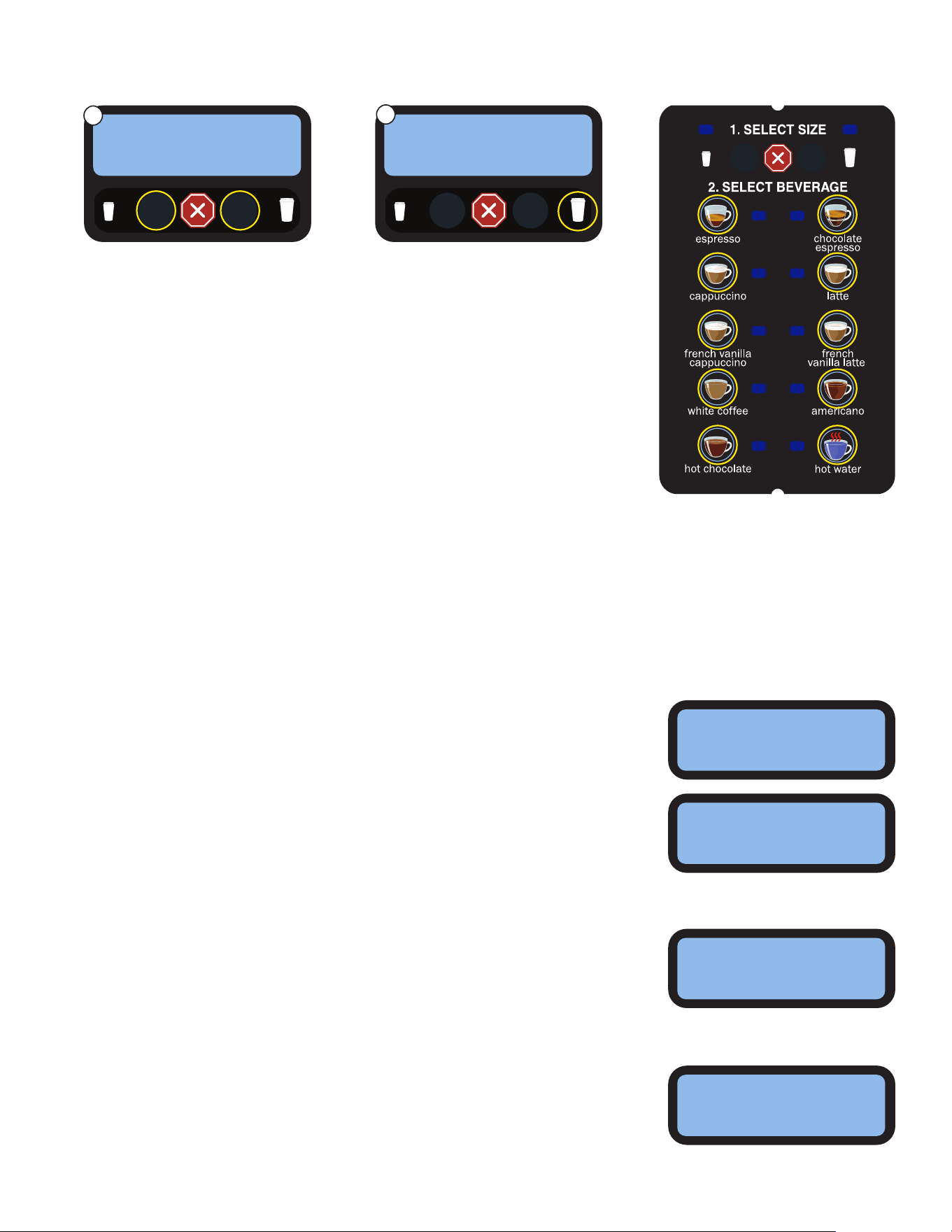
CREATING A “CUSTOM” BEVERAGE
A “CUSTOM” beverage may be edited/created for any dispense switch location. It is recommended that the
touch switch graphic insert be replaced with one which matches the beverage reassignments made in this
mode. All settings can be adjusted to preference.
1. Set the toggle switch to
Program mode.
2. Advance to the Set Espresso
Shots screen.
3. Press SELECT.
Use to
Navigate
PROGRAM MODE
PRESS TO ENTER
1. SELECT SIZE
Use to
Select
SET ESPRSO SHOTS
EXIT YES
1. SELECT SIZE
4. Sets the grinder run time for a
small espresso shot.
Navigate to the next setting.
Use to
Navigate
Use to
decrease
Use to
increase
SM ESP GRIND TIME
(-) #.# sec (+)
1. SELECT SIZE
5. Press a dispense switch to
perform a catch test for a
grind.
Navigate to the next setting.
Use to
Navigate
6. Sets the espresso pump
run time for pre-infusion of
tamped coffee. Zero seconds
for no pre-infusion.
Navigate to the next setting.
Use to
Navigate
Use to
decrease
Use to
increase
SM PREINFUSION
1. SELECT SIZE
1. SELECT SIZE
TEST SM GRIND TM
PRESS DISPENSE
OPERATING CONTROLS AND INTERFACE
NORMAL
PRGM
RINSE
continued >
MODIFYING THE TOUCH SWITCH FUNCTIONS
The function of the touch switch can be modified in three different ways:
1. Set for single cup size dispensing.
2. Disable a dispense switch.
3. Create a CUSTOM or ESPRESSO only beverage.
►
Set Espresso Shots
The sub-menus for adjusting an espresso shot are located under this option.
(-) #.# sec (+)
1 2
3
4 5
6
12
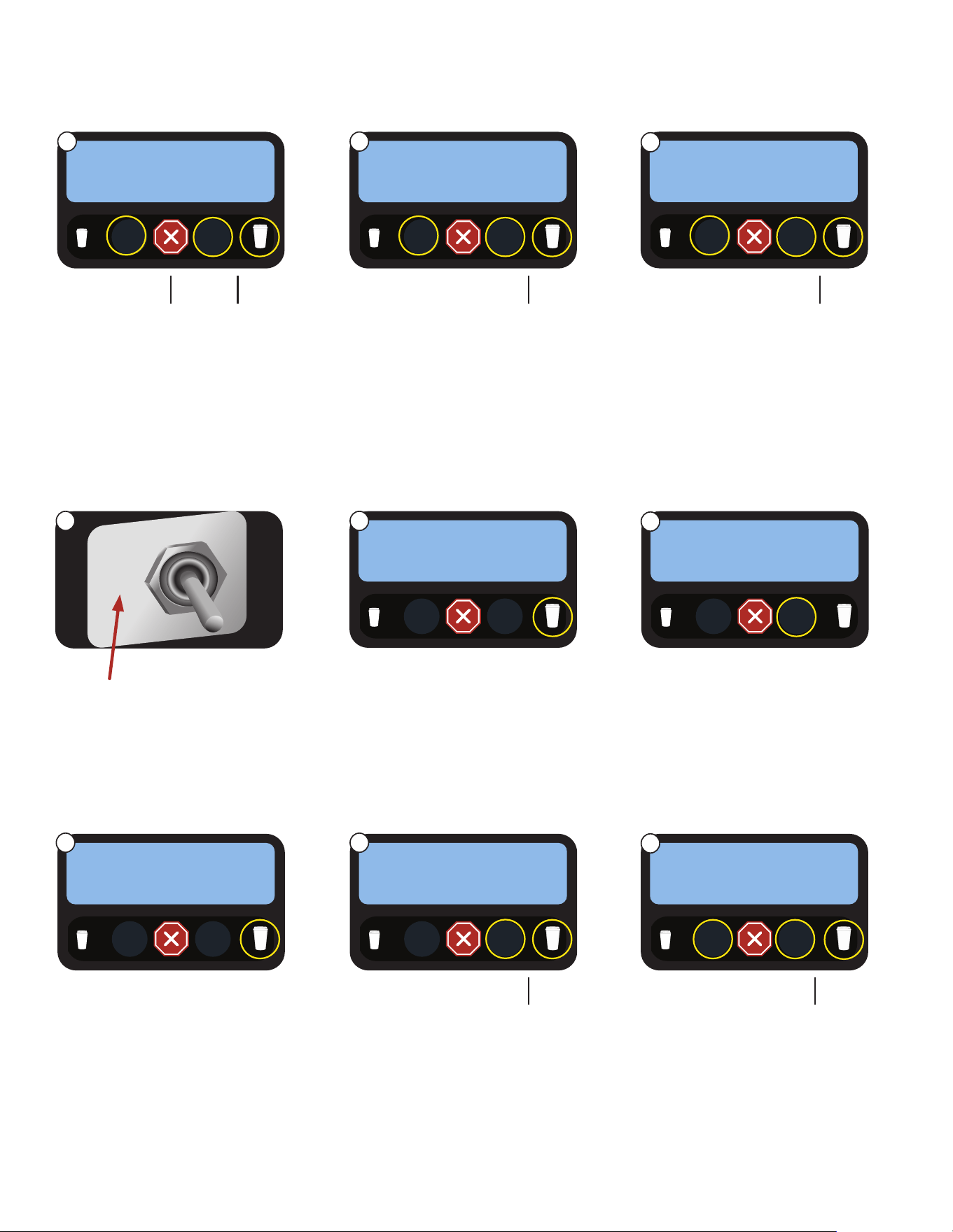
7. Sets the dwell time for a
small espresso.
Navigate to the next setting.
Use to
Navigate
Use to
decrease
Use to
increase
SM DWELL TIME
(-) #.# sec (+)
1. SELECT SIZE
8. Sets the total brew volume for
a small espresso shot. The
numeric value is flow ticks.
Navigate to the next setting.
Use to
Navigate
Use to
decrease
Use to
increase
9. The settings will repeat for
the large espresso shot.
Use to
Navigate
Use to
decrease
Use to
increase
LG ESP GRIND TIME
(-) #.# sec (+)
1. SELECT SIZE
1. SELECT SIZE
SM BREW VOLUME
(-) 95 (+)
►
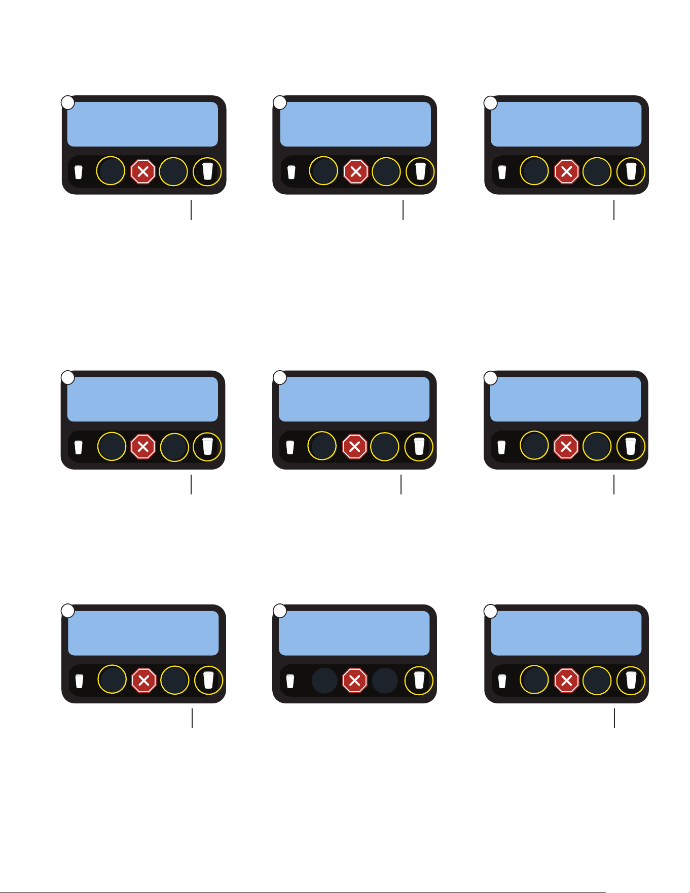
Recipe Setup
The sub-menus for adjusting recipes are located under this option.
1. Set the toggle switch to
Program mode.
2. Advance to the RECIPE
SETUP screen.
3. Press SELECT.
Use to
Navigate
PROGRAM MODE
PRESS TO ENTER
1. SELECT SIZE
Use to
Select
RECIPE SETUP ?
EXIT YES
1. SELECT SIZE
4. Single mode will only allow
one size beverage. Multi-drink
mode must be selected for
setting up small and large
beverages.
Navigate to the next setting.
Use to
Navigate
USER SELECT MODE
SINGLE MULTI
1. SELECT SIZE
5. You can navigate to any
switch to make a custom
beverage.
Press SELECT.
Use to
Navigate
Use to
Select
6. Navigate to BEVERAGE to
create a CUSTOM beverage
recipe.
Press navigate to enter the
next setting.
Use to
Scroll
1. SELECT SIZE
SETUP SW ## RCPE
NO YES
Use to
Navigate
1. SELECT SIZE
SWITCH ## RECIPE
(-) (+)
OPERATING CONTROLS AND INTERFACE
NORMAL
PRGM
RINSE
CREATING A “CUSTOM” BEVERAGE (continued)
►
Set Espresso Shots (continued)
Use to
Scroll
7 8
9
1 2
3
4 5
6
13
►
Recipe Setup (continued)
7. Sets the dispense time for a
small beverage.
Single cup mode will have
small or large to select from.
Navigate to the next setting.
Use to
Navigate
Use to
decrease
Use to
increase
SW 1 SMALL TIME
(-) #.# sec (+)
1. SELECT SIZE
8. Sets the dispense time for a
Large beverage.
Single cup mode will have
small or large to select from.
Navigate to the next setting.
Use to
Navigate
Use to
decrease
Use to
increase
9. Does beverage need an
espresso shot? If YES, it will
use the corresponding size
set for single touch or for the
size button selected in Multi.
Navigate to the next setting.
Use to
Navigate
Use to
select
Use to
select
ESPRESSO SHOT?
NO YES
1. SELECT SIZE
1. SELECT SIZE
SW 1 LARGE TIME
(-) #.# sec (+)
14. This will provide a catch test
to see how much product
dispenses from the hopper.
Navigate to the next setting.
Use to
Navigate
TEST RT HOPPER
PRESS DISPENSE
1. SELECT SIZE
15. Choose the order in which the
ingredients dispense.
Navigate to the next setting.
Use to
Navigate
Use to
select
Use to
select
1. SELECT SIZE
DISPENSE ORDER
(-) (+)
10. Options are any of three
hoppers or dilution. Cannot
choose “NONE”.
Navigate to the next setting.
Use to
Navigate
Use to
select
Use to
select
1st POWDER/DIL ?
(-) (+)
1. SELECT SIZE
11. Options are any of three
hoppers or dilution. “None”
can be selected.
Navigate to the next setting.
Use to
Navigate
Use to
select
Use to
select
1. SELECT SIZE
2nd POWDER/DIL ?
(-) (+)
13. Sets the amount of product
used for the recipe that comes
from the hopper. If a hopper
is not used in the recipe, this
screen will not appear.
Navigate to the next setting.
Use to
Navigate
Use to
decrease
Use to
increase
1. SELECT SIZE
HOPPER RIGHT STR
(-) (+)
OPERATING CONTROLS AND INTERFACE
continued >
12. Sets the percentage of run
time used for the first
selected ingredient.
Navigate to the next setting.
Use to
Navigate
Use to
decrease
Use to
increase
1. SELECT SIZE
HPR MDLE PORTION
(-) 85.0% (+)
7 8
9
10 11
12
13 14
15
14
TOUCHLESS SENSITIVITY SELECTION OPTIONS
OPERATING CONTROLS AND INTERFACE
NOTE: Your Crescendo must be fitted with a Gen 2 PCAP with software version 01.20 or higher, and the
main I/O board with software version 00.45 or higher to modify the Touch Settings on this machine.
Go to www.bunn.com to view Crescendo Programming Manual or BUNN Online Learning Center for
more information on updating.
The Sensitivity option is available for both TOUCH and TOUCHLESS operation modes. The recommended
initial setting for TOUCH is “NORMAL”, and the recommended initial setting for TOUCHLESS is “HIGH”.
1. Set the toggle switch on
inside of the door to Program
mode.
2. Advance to the Calibration
screen.
3. Press YES to enter the
Calibration sub-menu.
Navigate through the sub-
menu until you see a screen
that says TOUCH SETTINGS.
Use to
Navigate
PROGRAM MODE
PRESS TO ENTER
1. SELECT SIZE
Use to
Select
Use to
Select
CALIBRATION
EXIT YES
1. SELECT SIZE
NORMAL
PRGM
RINSE
6. Select the sensitivity level for
the Touchless or Touch mode
chosen on previous screen.
NOTE: It is recommended to
try “Normal” for Touch and
“High” for Touchless.
Press large cup to navigate
to next option screen.
5. Press YES to enable
touchless dispense mode.
Or, press NO to enable touch
dispense mode.
Press large cup to navigate
to next option screen.
TOUCHLESS MODE
1. SELECT SIZE
1. SELECT SIZE
4. Press YES to enter the
TOUCH SETTINGS sub-menu.
TOUCH SETTINGS
EXIT YES
1. SELECT SIZE
NO YES
SENSITIVITY
NORMAL HIGH
continued >
Use to
Select
Use to
Select
Use to
Select
Use to
Select
1 2
3
4 5
6
15
TOUCHLESS SENSITIVITY SELECTION OPTIONS (continued)
OPERATING CONTROLS AND INTERFACE
7. The CONFIRM DISPENSE
screen allows you to deter-
mine if you want to require
the user to press the bever-
age select button twice to get
a beverage to dispense.
• If YES is chosen; the
selected beverage button will
flash its LED while waiting for
the user to press it again to
begin the dispense process.
• Press large cup to navigate
to next option screen.
8. This screen allows you to try
the 10 beverage dispense
buttons with the Touch or
Touchless mode and the
selected Sensitivity adjustment
(Normal to High), to see how
the touch panel responds.
• Once done, press the large
cup to navigate to next option
screen.
• If you want to try more
sensitivity or mode options;
press the small cup to navi-
gate backwards.
1. SELECT SIZE
Use to
Navigate
TEST SWITCHES
UseSwitchToTest
READY TO BREW
SELECT SIZE
CONFIRM BEVERAGE SCREENS (when activated)
Screen text examples for multi-touch and single touch operation of the Crescendo machine.
Multi-Touch Selection Screens
SELECT BEVERAGE
TO DISPENSE
Single Touch Selection Screen
READY TO BREW
SELECT BEVERAGE
Confirm Beverage Screen
SELECT BEVERAGE
AGAIN TO CONFIRM
The CONFIRMATION screen will time out after 20 seconds of inactivity,
and will also cancel out if the user presses any other buttons on the
touch panel.
If the CONFIRM DISPENSE option is not active, then the beverage
should begin to dispense as soon as the beverage key is selected the
first time.
If the CONFIRM BEVERAGE screen is active, it will go there after the
beverage is selected and flash the beverage LED until the user selects
the beverage again.
CONFIRM DISPENSE
NO YES
1. SELECT SIZE
Use to SelectUse to Select
7
8
16
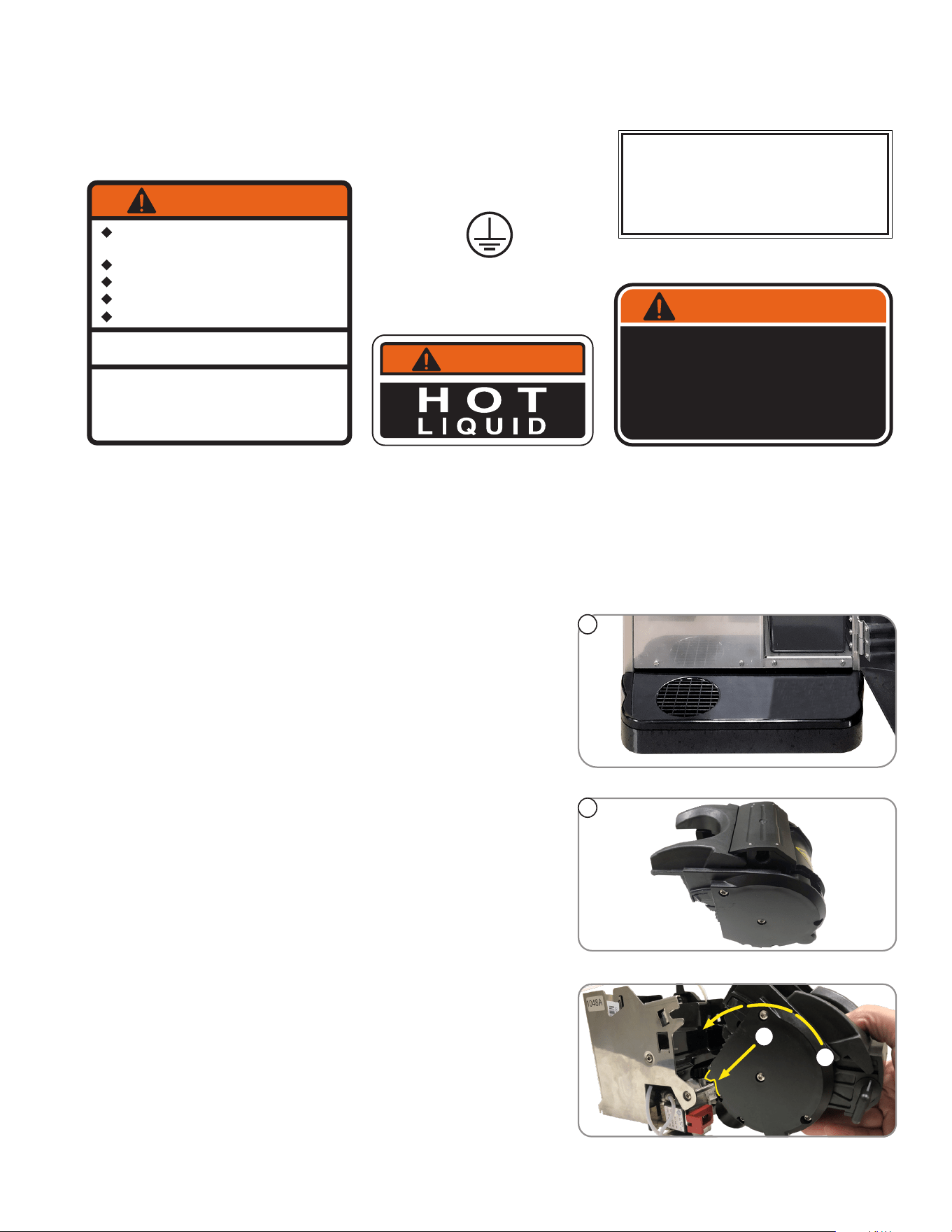
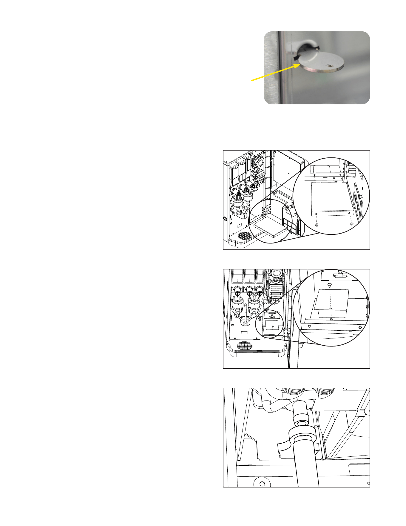
Service Key
Figure 2
Remove the chassis bottom cover
Connect a 5MM ID tube to the drain fitting
Remove grounds bin support panel
The machine can be setup to dispose of the used coffee
grounds through an opening in the counter, into a waste bin,
for higher waste capacity.
Countertop and Machine Modifications for
Through Counter Waste Option
1. Use template (Bunn #54427.0000) to locate the cutout
hole in the countertop.
2. Open the front door on Crescendo, and remove the
grounds bin.
3. Remove the two screws that secure the grounds bin
support panel, then remove the panel.
4. Remove screw holding the chassis bottom cover, then
remove the cover.
5. Used coffee puck will now fall through the opening in
the chassis.
6. Position the Crescendo so that the opening in the bottom
of the machine coincides with the hole in
the countertop.
7. To direct the brewing waste water through the counter,
disconnect the drain tube from the fitting on the bottom
of the espresso drive.
8. Connect a 5MM ID tube to the drain fitting, and
direct the tube through the opening in the bottom of
the chassis.
The dispenser is equipped with a door interlock safety switch,
which prevents the operator from being exposed to the moving
parts of the espresso brewer if the door is open.
The switch may be overridden by a qualified service technician
by inserting the service key, (BUNN PN 51953.0001) into the
opening of the mixing chamber panel, then turn about 15
degrees to position, as shown in Figure 2.
DOOR SAFETY INTERLOCK
THROUGH COUNTER OPTION
continued >
17
continued >
In this mode, the machine will operate in a low power mode during off hours to save energy. The display backlight
will be turned off, and the display message will toggle between “Energy Saver/Mode Enabled” and “Change to
Normal/Mode to Clear”. The dispense buttons are disabled so that no beverage dispensing is allowed. The tank refill
and powder (soluble) tank heater are disabled. The espresso tank temperature setting is reduced to 130ºF (54ºC).
Software Setup for Through Counter Option
THROUGH COUNTER OPTION
3. Press the LARGE cup button
to navigate to the LOCKS/
DISABLES menu.
2. Place in PROGRAM mode.
1. Power the machine.
1. SELECT SIZE
PUCK BIN
NO EXIT YES
1. SELECT SIZE
LOCKS/DISABLES
EXIT YES
1. SELECT SIZE
LOCKS/DISABLES
EXIT YES
4. Press the YES button, then the
LARGE cup size button until the
screen displays the PUCK BIN screen.
2. Press the YES button, then the LARGE
cup size button until the screen
displays the ENERGY SAVER? screen.
Use to select Use to Navigate
Use to select Use to Navigate
5. In the default menu, YES will be
flashing. Press the button under
NO to disable the PUCK BIN mode.
Use to select
NORMAL
PRGM
RINSE
Use to Navigate
Use to Navigate
PROGRAM MODE
PRESS TO ENTER
PROGRAM MODE
PRESS TO ENTER
1. SELECT SIZE
1. SELECT SIZE
1. SELECT SIZE
PUCK BIN
NO EXIT YES
6. When NO is flashing on the
display, press the button under
EXIT to return to the main screen.
Use to select
1. In PROGRAM mode, press the
LARGE cup button to navigate
to the LOCKS/DISABLES menu.
To enable Energy Saver Mode
NORMAL
PRGM
RINSE
1. SELECT SIZE
4. When YES is flashing on the
display, press the button under
EXIT to return to the main screen.
5. Place the NORMAL/
PROGRAM/RINSE switch to
the NORMAL position.
Use to select
ENERGY SAVER MODE
1
5
1
4
2 3
6
2
5
4
NORMAL
PRGM
RINSE
7. Place the NORMAL/
PROGRAM/RINSE switch to
the NORMAL position.
1. SELECT SIZE
ENERGY SAVER?
NO EXIT YES
3. In the default menu, NO will be
flashing. Press the button under
YES to enable the ENERGY
SAVER mode.
Use to select
7
3

18
The use of a damp cloth rinsed in any mild, non-abrasive, liquid detergent is recommended for cleaning all surfaces on
Bunn-O-Matic equipment.
Exterior Surfaces
• Do not use any abrasive materials.
• Use a soft, dry cloth to wipe down the exterior surfaces of the dispenser to maintain the luster of the stainless steel finish.
• Wash the stainless steel exterior surfaces of the dispenser with warm, soapy water. Rinse with warm, clear water. If
the water is hard, wipe the dispenser dry with a soft cloth to prevent water spotting.
• Stainless steel polish may be used if it is sprayed on a cloth before the cloth is used to wipe down the exterior
surfaces of the dispenser.
DAILY: Parts Washing
1. Remove and wash the drip tray and drip tray cover in a mild detergent solution. Rinse thoroughly.
2. Wipe the lower front panel, door, and cabinet with a clean damp cloth.
WEEKLY: Parts Washing
1. Remove the elbows and slide gates from all hoppers. Disconnect the elbows from the outlets of both mixing chambers.
2. Remove the powder mixing chambers, steam traps, frothers and mixing chamber bases.
3. Remove the dispense hoses from the dispense nozzle assembly.
4. Clean all parts removed in warm soapy water. Use Bunn P/N 26367.0000 or 49827.0000 cleaning brush provided to
clean bores and orifices. Rinse in cold water.
5. Prepare one-gallon (3.8 liter) of sanitizing solution with at least 100 ppm of available chlorine in 120°F (48.9°C
water. Soak all cleaned parts in sanitizing solution for 5 minutes, then allow to air dry.
6. Rinse cleaning brush, dip in sanitizing solution, and brush the bore of both dispense nozzles.
NOTE: Repeat this procedure for each nozzle separately.
7. When reassembling parts, be sure to align arrow on frother disk with flat on whipper motor shaft, and rotate tab on
whipper base clock wise to the vertical position to lock mixing chamber.
GENERAL CLEANING
continued >
To place the unit in ENERGY SAVER Mode
ENERGY SAVER MODE
NOTE: If a rinse cycle has taken place, and the switch is left in the RINSE position, the ENERGY SAVER mode will
become active ten minutes after the rinse cycle was completed. To exit the ENERGY SAVER mode, return the NORMAL/
PROGRAM/RINSE switch to the NORMAL position.
NORMAL
PRGM
RINSE
1. SELECT SIZE
ENERGY SAVER?
NO EXIT YES
1. Open the door, and place the
NORMAL/PROGRAM/RINSE
switch in the RINSE position.
2. After ten minutes with the
switch in the RINSE position,
the ENERGY SAVER mode
will become active.
1 2
19
a
b
c
1
2
3
4
6
7
5
1 x 7d
7
1 x 24h
1. Lave la cámara de batido colocando RUN/PRO GRAM/
RINSE en la posición de lavado RINSE, y apretar el
botón bajo RINSE. Luego aprete cualquier botón
dispensador de bebida.
2. Empuje la compuerta deslizante en frent de los codos
de la tolva para cerrarla. Retire las tolvas, llene con el
producto y reemplace la tolva en el dispensador.
3. Vacie la bandeja de goteo y limpiela con un
detergente liquido suave no abrasivo.
1. Rinse out Whipper Chambers by placing the RUN/
PROGRAM/RINSE switch in the RINSE position, then
press the button under RINSE followed by pressing
any beverage dispense button.
2. Push the slide gates on the front of the hopper elbows
inward to close. Remove hoppers, refill with product,
and replace hoppers into dispenser.
3. Empty Drip Tray and wash in a solution of dish
detergent.
NOTICE:
The cleaning instructions noted above are for non-dairy sugar based food products. When dispensing any other food
product, the cleaning cycle for the whipping chamber assembly and ejector elbow must be performed daily.
NOTA:
Las instucciones de limpieza descritas anteriormente excluyen productos lacteos azucarados. La limpieza de las
camaras de mezcla y de los codos de salida de cada tolva deber
á
realizarse diariamente.
a. Wash
b. Rinse
c. Sanitize
d. Dry
a. Lave
b. Enjuague
c. Desinfecte
d. Seque
1
3
2
4
5
6
7
8
9
10
1 of 3 hopper groups
shown. Each should
be cleaned weekly,
or as needed.
CLEANING
20
1. SELECT SIZE
CLEANING
RINSE CYCLE (Required Daily)
1. Open the door and place the NORMAL/PROGRAM/RINSE switch in
the RINSE position.
2. Close door and place a minimum 400ml container under the
dispense nozzles.
3. Press the button under RINSE on the screen.
4. Press any beverage selection button.
5. The dispenser will automatically run hot water through both
soluble mixing chambers, and flush the espresso brew chamber
with hot water.
6. After rinse cycle is complete, discard the rinse water collected in
the container.
7. Open the dispenser door, and place the NORMAL/PROGRAM/RINSE
switch in the NORMAL position.
NORMAL
PRGM
RINSE
NORMAL
PRGM
RINSE
continued >
SELECT MODE
RINSE CLEAN
1
2
3
7
21
continued >
CLEANING
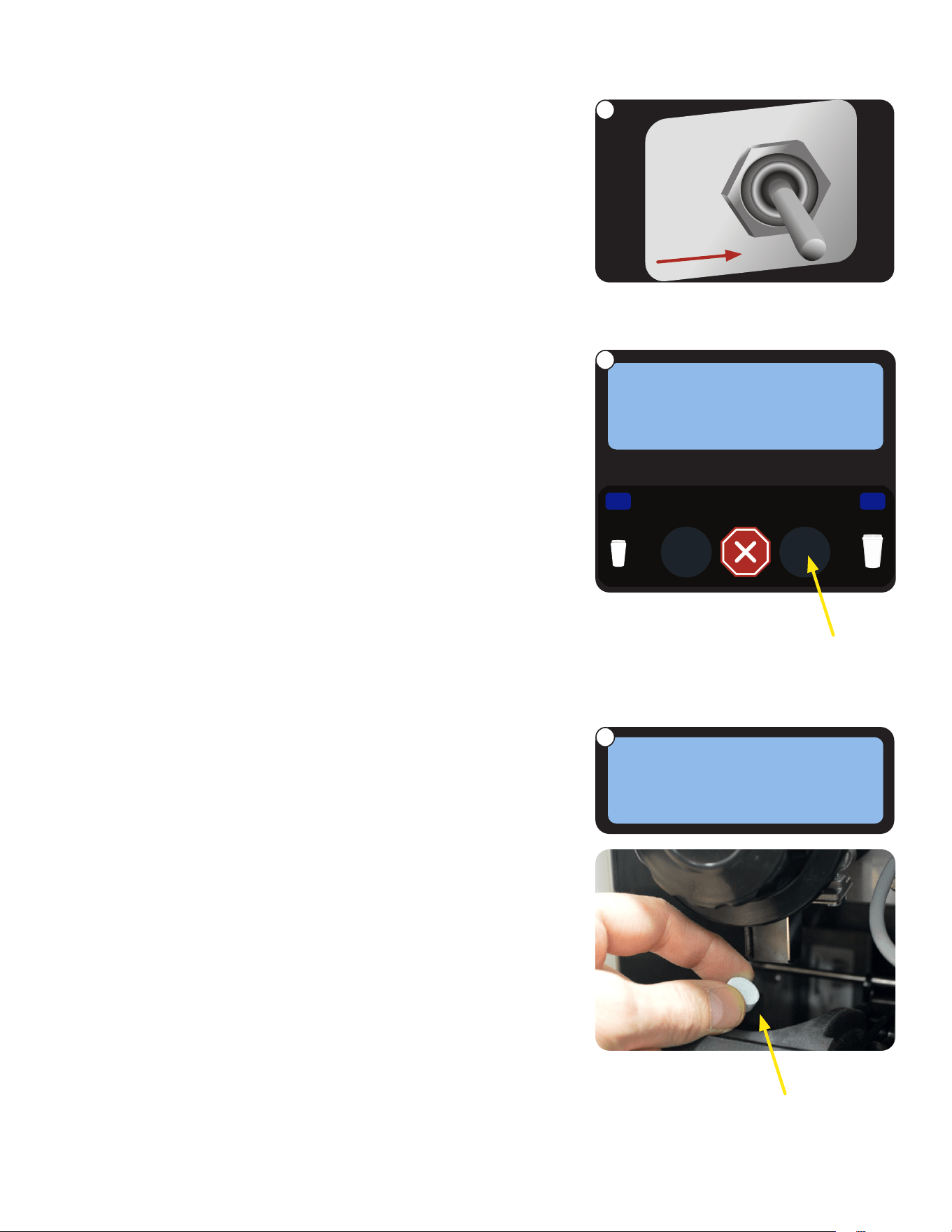
Add cleaning
tablet here
1. Open the door and place the NORMAL/PROGRAM/RINSE switch in
the RINSE position.
2. Press the button under CLEAN on the screen.
3. When the screen prompts ADD CLEANING TABLET, open the
dispenser door, and drop a cleaning table into the opening of the
espresso brew chamber as shown.
1. SELECT SIZE
NORMAL
PRGM
RINSE
SELECT MODE
RINSE CLEAN
ADD CLEANING
TABLET NEXT
CLEAN CYCLE: Weekly
1
2
3
22
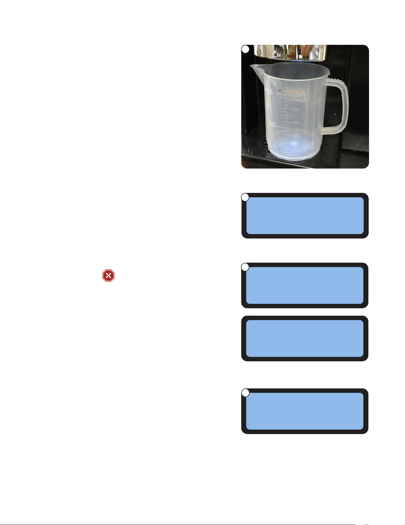
4. Close dispenser door and place a minimum 500ml container under
the dispense nozzles.
5. Press the button under NEXT.
CLEANING
continued >
8. When the cleaning cycle is complete, screen will display
SELECT MODE/ RINSE__ CLEAN.
9. Discard the waste water collected from the cleaning cycle.
10. Open the dispenser door, and place the NORMAL/PROGRAM/RINSE
switch in the NORMAL position.
7. During the cleaning cycle, the screen with display CLEANING CYCLE
IN PROGRESS/PRESS
TO STOP.
6. When screen displays PRESS DISPENSE TO START, press any
beverage dispense button to begin cleaning cycle.
PRESS DISPENSE
CLEANING CYCLE
TO START
IN PROGRESS
PRESS ANY BUTTON
SELECT MODE
TO STOP
RINSE CLEAN
CLEAN CYCLE: Weekly (continued)
4
6
7
8
23
continued >
CLEANING
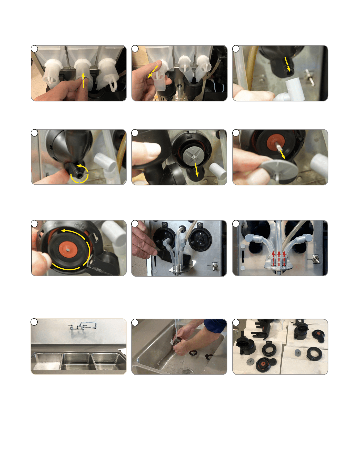
WEEKLY: Parts Washing and Sanitizing
1 2 3
2. Remove hoppers. 3. Remove the elbow fittings from
both mixing chambers.
1. Push slide gates on the hopper
elbows in to close.
4
4. Rotate tab at bottom of mixing
chamber bases. Twist counter
clockwise to release bases.
6
5
6. Remove frother disks (Impellers)
from shafts by pulling straight
out.
5. Remove mixing chambers by
pulling straight out.
7. Rotate tab on mixing chamber
bases further counter clockwise,
and remove from shafts by pulling
straight out.
7
8. Use flat brush to clean dispense
tube connectors area.
8
9
9. Remove dispense tubes from
dispense nozzle assembly.
10. Prepare one-gallon (3.8 liter) of
sanitizing solution with at least
100 ppm of available chlorine in
120°F (48.9°C) water. Clean all
parts in compartment sink.
NOTE: Do not use any abrasive
materials.
10
12. Soak all cleaned parts in
sanitizing solution for 5 minutes,
then allow to air dry.
11. Rinse parts thoroughly.
12
11
►
WHIPPER COMPONENTS
24
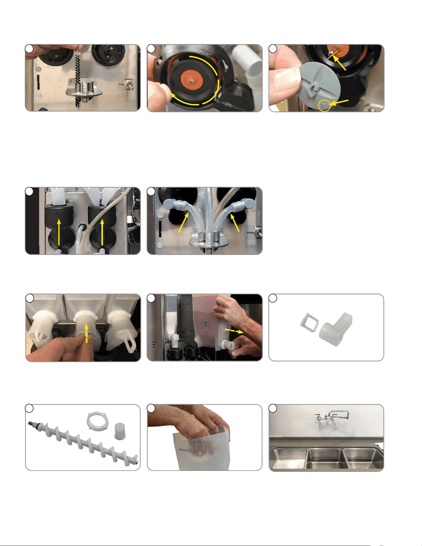
CLEANING
1513 14
15. Replace frother disks. Confirm
that the arrows are aligned with
the flat side of the whipper motor
shafts.
14. Replace whipper base. Rotate
tab on whipper base clockwise
to the vertical position to lock
mixing chamber.
NOTE: Ensure O-ring and
shaft seal are in place during
re-assembly.
13. Rinse cleaning brush, dip in
sanitizing solution, and brush the
bores of the dispense nozzles.
Repeat this procedure for each
nozzle separately.
17. Replace dispense tubes.
NOTE: Confirm tubes don’t kink.
16. Replace mixing chambers.
1716
►
HOPPER COMPONENTS
1
3
2
1. If not already removed, push the
slide gates on the hopper elbows
in to close.
2. Remove hoppers, and empty
product in a separate clean
container.
3. Remove powder hopper dispense
elbow.
4. Remove rear auger nut, then
pull the auger and the rear auger
bearing out of the hopper.
5. Remove mixing wheel with
springs from hopper by spreading
the hopper side wall with hand to
release wheel from hopper.
6. If not already done, prepare one
gallon (3.8 liter) of sanitizing
solution with at least 100 ppm
of available chlorine in 120°F
(48.9°C) water.
4 5 6
continued >
WEEKLY: Parts Washing and Sanitizing (continued)
25
CLEANING
►
HOPPER COMPONENTS (continued)
WEEKLY: Parts Washing and Sanitizing (continued)
7. Clean all parts in a 3
compartment sink. Do not
use any abrasive materials.
Rinse parts thoroughly.
7
8. Soak all cleaned parts in sanitiz-
ing solution for 5 minutes, then
allow to air dry.
9. Reassemble each hopper.
8 9
11. Reinstall hoppers onto compart-
ment platform. Ensure auger and
hopper locator peg are properly
seated in position.
12. All hoppers re-installed.10. Refill hoppers with product.
10 11
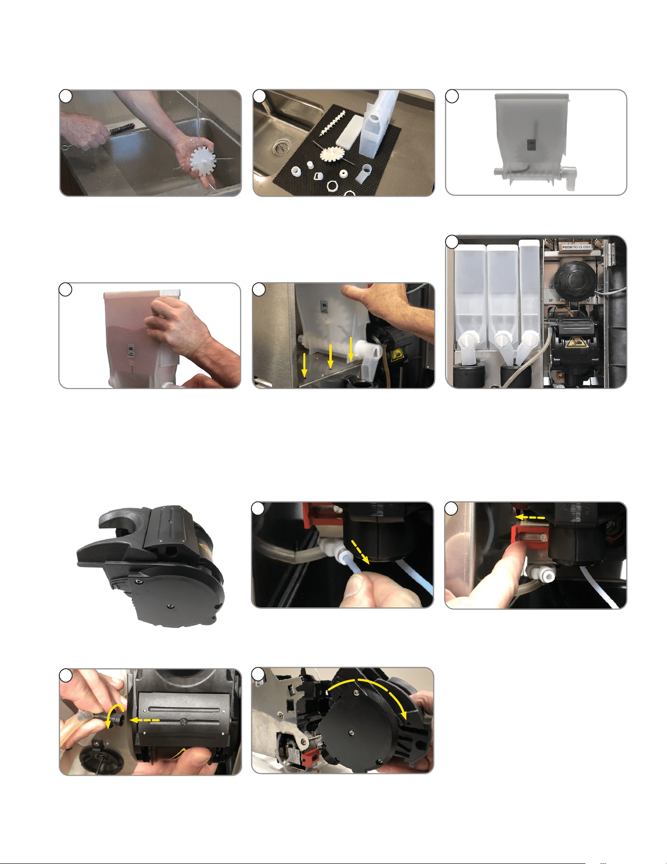
BI-WEEKLY (or Every 1,000 Cycles): Espresso Brew Chamber
►
REMOVE BREW CHAMBER FROM ESPRESSO DRIVE
4. Pull brew chamber group out.3. Remove brew chamber outlet tube.
NOTE: Turn elbow until it releases
from hole.
2. Slide red lock to left to unlock.1. Remove water inlet tube.
NOTE: To release, press ring on
fitting, and pull tube out.
1 2
3
4
Brew Chamber
12
26
CLEANING
►
SEPARATING BREW CHAMBER PARTS
1. Slide cake pusher forward.
2. Pull sieve head out from brew
chamber.
4. Remove sieve head.
1
2
3
3. Remove cake pusher.
4
>
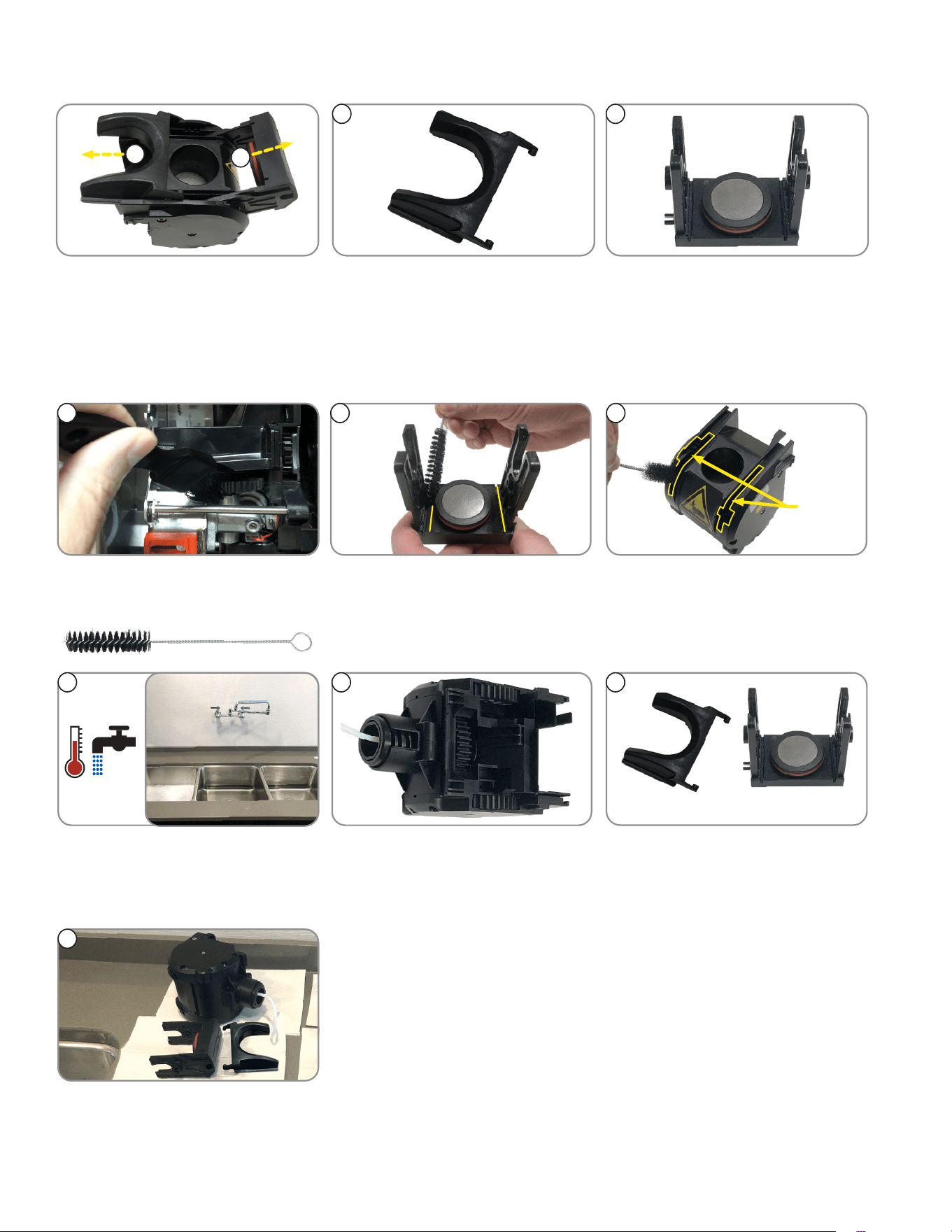
CLEANING BREW CHAMBER PARTS
1
3
Gear
Channels
2
1. Brush espresso drive gears. 3. Use brush to clean brew chamber
housing and gear channels.
2. Brush sieve head.
NOTE: Pay special attention to
the channels.
continued >
54
Cake Pusher
6
Sieve Head
5. Clean all sides of brew chamber.
NOTE: Turn gears in back of brew
chamber to clean all sections.
6. Clean cake pusher and sieve
head in warm water.
4. Use lukewarm water only to rinse
all parts.
7. Place all parts out to dry.
7
27
CLEANING
BI-WEEKLY (or Every 1,000 Cycles): Espresso Brew Chamber (continued)
►
REASSEMBLING GROUP HEAD
32
Correct
1
Incorrect
1. Confirm all gears are aligned,
and the slots to put the sieve
head are open.
NOTE: Gap in gears should be
showing.
2. Replace cake pusher in channels. 3. Place sieve head in gear
opening, and push in.
54
4. Align cake pusher tabs into slots
on sides of sieve head.
5. Press sieve head and cake
pusher forward until seated.
►
REATTACHING GROUP HEAD TO ESPRESSO DRIVE
1
2
4
5
3
NORMAL
PRGM
RINSE
6
7
3. Connect brew chamber
outlet tube.
4 Slide red lock to right until
it locks.
5. Connect water inlet tube.
1. Place groove on lower front of
brew chamber onto mounting bar
on espresso drive.
2. Rotate the top of group head
toward rear of machine until it
snaps into place.
6. Place the NORMAL/PROGRAM/
RINSE switch in the NORMAL
position.
7. Close door.

28
Bunn-O-Matic
®
Corporation recommends that preventive maintenance be performed at regular intervals.
Maintenance should be performed by a qualified service technician. For Technical Service, contact
Bunn-O-Matic Corporation at 1-800-286-6070.
NOTE: Replacement parts or service caused by failure to perform required maintenance is not covered by warranty.
Cycle (months) Item Part Number
6 PM KIT, 6 MONTHS CRESCENDO 54866.0000
12 PM KIT, 12 MONTHS CRESCENDO 54867.0000
ADJUSTMENTS
Adjustable Variables Used to Create A Perfect Shot of Espresso Topped with Crema
The primary 2 variables that you will adjust to achieve your ideal double shot espresso pour time will be the
coffee particle size and the dosage targets.
PREVENTIVE MAINTENANCE
Adjust the Coffee Particle Size
The particle size of the ground coffee can be adjusted for optimal espresso brewing.
DO NOT change the grind particle size significantly. Change coffee coarseness in 1 hashmark increments,
as it will change the grind rate, thus the amount of coffee ground and brew/pour time.
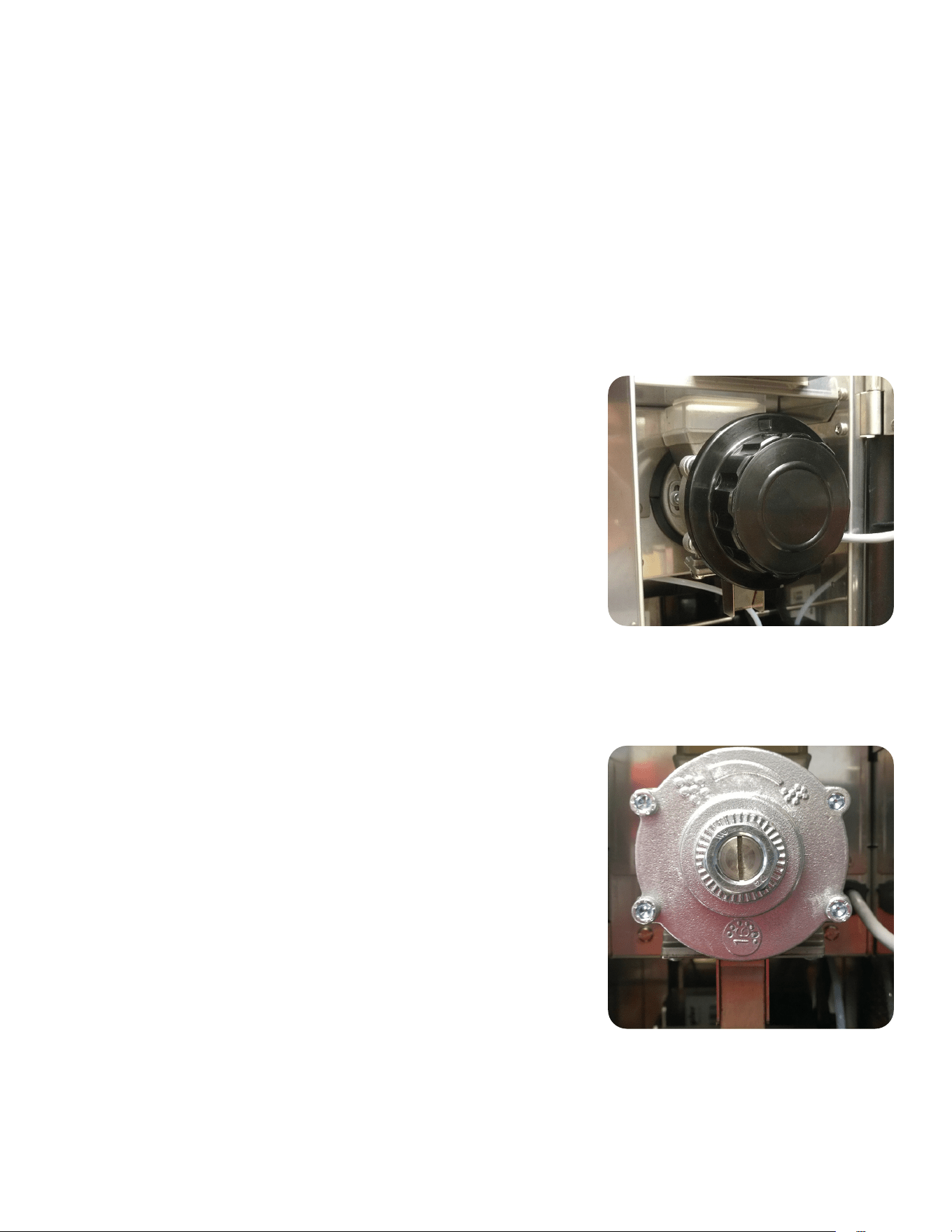
The grinder adjustment screw will be set from the factory to an approximate particle size
setting for espresso (11 Hashmarks).
continued >
Variables
1. Coffee Particle Size: See "Adjust the Coffee Particle Size" below.
2. Espresso & Water Dosage: Adjustable
3. Espresso Water Temperature: Factory Default Setting is 215° F.
Adjustable from 190°-218°
Defaults
Single 7 g 30 ml
Double 12 g 60 ml
Brew/Pour Time Target
• 17-23 seconds from when grinder stops to cup takeaway.
NOTE: Adjustments are optimized for double shots. The single shot pour time will be shorter because of less water.
Once the double shot has been calibrated, the grinder coarseness adjustment is complete. The only
adjustment to perform is setting the espresso & water dosage for a single shot espresso.
1. First, ensure espresso beans are in the hopper. Open the door, and slide the espresso brew group lock
to the left to unlock the brew group. Tip the top of the brew group head towards the front of the machine
to disengage from the espresso drive, then remove brew group from the drive.
2. Enter program mode and scroll to SET ESPRESSO SHOTS menu. Enter and scroll to TEST LG GRIND
TIME menu. Place cup under grinder chute to catch coffee grounds during grind adjustment. Press the
espresso button to start the grinder dispense timer. Adjust the grinder adjustment screw ONLY WHILE
THE GRINDER IS OPERATING until the grind particle size is desired or matches a desired grind sample.
3. After setting the grind particle size, tare (zero) cup on weigh scale, then place cup under grinder chute
and press the espresso button to start the grinder dispense timer. Then, weigh the dispensed grounds.
Adjust the grind time and keep repeating the grind throw test until desired weight is achieved.
NOTE: Steps 1 thru 3 will take some back and forth adjustments to achieve the target brew time. You
should end up with a dark color espresso, topped with a tan colored crema.
29
Adjustment Knob
Adjustment Screw with Locking Nut
ADJUSTMENTS
Style: Adjustment Knob (Figure 1)
The particle size of the ground coffee can be adjusted for optimal brewing
of the espresso.
NOTE: BUNN recommends to rotate knob in 1 click increments to
achieve desired coarseness.
1. Turn knob counterclockwise to increase the particle size (coarse) of the
ground coffee.
2. Turn the knob clockwise to decrease the particle size (fine) of the
ground coffee.
CAUTION! If there is ground coffee in the grinder, this adjustment
should only be made while the grinder is running.
3. Use SET ESPRESSO SHOTS, TEST SM or LG GRIND functions to
operate the grinder for making particle size adjustment.
Style: Grinder Adjustment Screw with Locking Nut (Figure 2)
The particle size of the ground coffee can be adjusted for optimal espresso brewing.
The lock nut replaces the grinder knob to prevent tampering of grind adjustment.
NOTE: BUNN recommends to rotate adjustment screw in 1 hashmark
increments to achieve desired coarseness.
1. The grinder adjustment screw will be set from the factory to an
approximate particle size setting for espresso (11 Hashmarks).
2. Loosen locknut and use large flat blade screwdriver to rotate
adjustment screw clockwise or counter clockwise to desired
particle size, use screwdriver to hold adjustment screw while
tightening lock nut.
CAUTION! If there is ground coffee in the grinder, this adjustment
should only be made while the grinder is running
3. Use SET ESPRESSO SHOTS, TEST SM or LG GRIND functions to
operate the grinder for making particle size adjustment.
(continued from previous page)
4. Next, scroll through sub menus until LG BREW VOLUME is displayed. Ensure the tic number is set to
your desired finished shot amount.
NOTE: 3.0 tics = 1.0 mil, Default 190 tics divide by 3.0 = 63.33 mils. This is your brew volume target
63.33mils for a double shot. The extra 3.33 mils most likely will be absorbed in the espresso puck
resulting around 60 mils of finished product/double shot.
5. Reinstall the brew group, return switch to the NORMAL position and close door. Make a large espresso
to see if your brew/pour time is within the 17-23 seconds.
NOTE: Anytime you make an adjustment to the coffee coarseness, a shot must be discarded between
adjustments. If the pour is too slow or too fast, repeat all steps until you are within the 17-23 seconds
brew time.
30
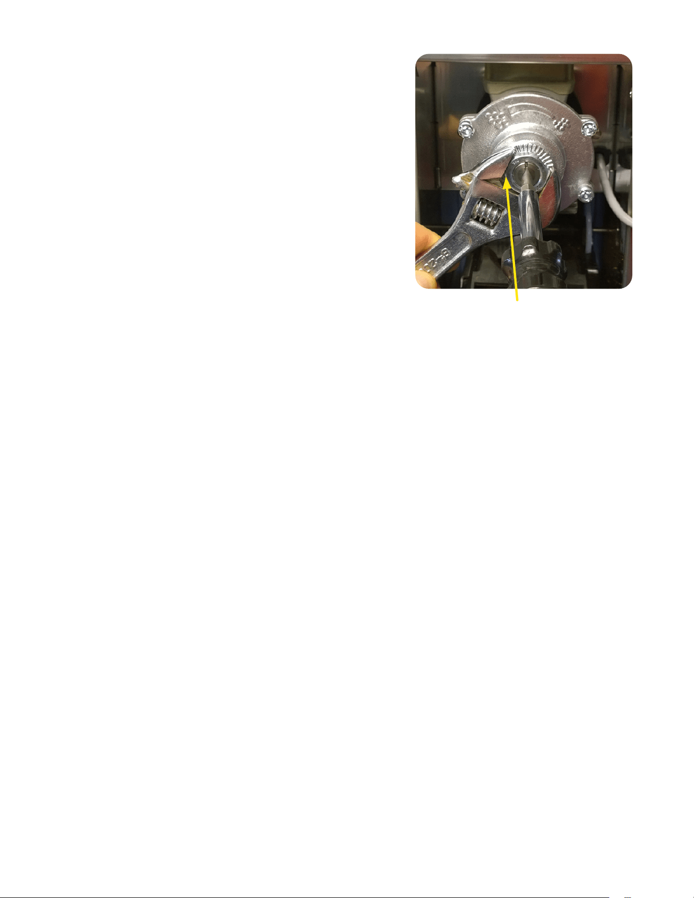
Procedure Setting Grinder Adjustment Screw Back to
Factory Setting
The procedure for setting the adjustment screw back to a factory setting
after dismantling and cleaning the burrs.
1. Bean hopper removed or chute closed. Place switch in Program
position. Go to display screen and scroll to “SET ESPRESSO SHOTS”
menu. Enter and scroll to “TEST LG GRIND TIME” menu. Loosen
locknut and use large flat blade screwdriver to rotate adjustment
screw. Press the espresso button to start the grinder motor, while
the motor is running, slowly rotate the adjustment screw inside the
nut clockwise. When a “chirping” sound of the burrs touching is
heard, rotate counter clockwise just until the chirping stops.
2. Reference the adjustment screw slot and mark the burr rotor cap with
0. Then rotate the adjustment screw 11 hashmarks counter clockwise
from 0 to set back to a factory setting. Mark the burr rotor cap to
indicate 11 hashmark setting. Holding the screw with the screwdriver,
tighten the hex nut. Make sure after tightening nut, the setting is still
lined up at the 11 hashmarks from zero.
Grinder Throw Weight Adjustment
1. Open the door, and slide the espresso brew group lock to the left to unlock the brew group.
2. Tip the top of the brew group head towards the front of the machine to disengage from the espresso drive, then
remove brew group from the drive.
3. Place the NORMAL/PROGRAM/RINSE switch in the PROGRAM position.
4. Press the Large Cup button to the SET ESPRESSO SHOTS menu, then press the button under YES.
5. Press the Large Cup button to TEST SM GRINDTM.
6. Place a small container on a scale, and tare container.
7. Hold the container under the grinder chute, and press any beverage dispense button.
8. Grinder will run for the time set for a small (single shot) espresso, then stop.
9. Repeat several times, and average the weight.
10. To change the weight, press the Small Cup button to SM ESP GRIND TIME.
11. Us the buttons below the (-) and (+) button to increase or decrease the grind time.
12. Press the Large Cup button to TEST SM GRIND to test new grind time.
13. Press the Large Cup button to TEST LG GRIND to test the large (double shot) grind weight.
14. Press the Small Cup button to LG ESP GRIND TIME to adjust the grind time for a large (double shot) espresso,
if required.
15. After the grind adjustments have been tested and adjusted, place the NORMAL/PROGRAM/RINSE Switch in the
NORMAL position, and exit program mode.
16. Reinstall the espresso group head back onto the espresso drive.
Loosen Locking Nut to allow
Adjustment Screw to move
ADJUSTMENTS
31
1
3
7
4
Figure 2
Figure 1
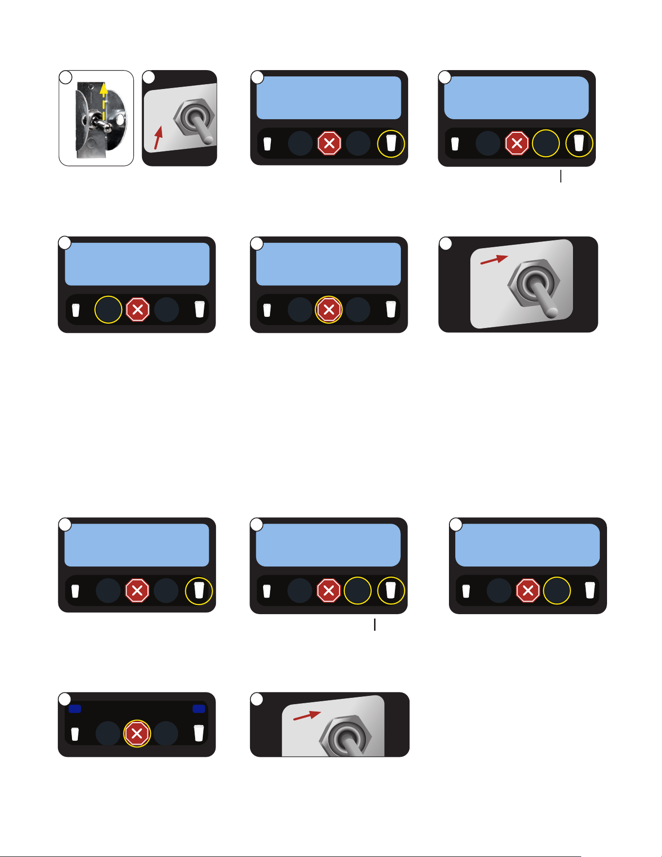
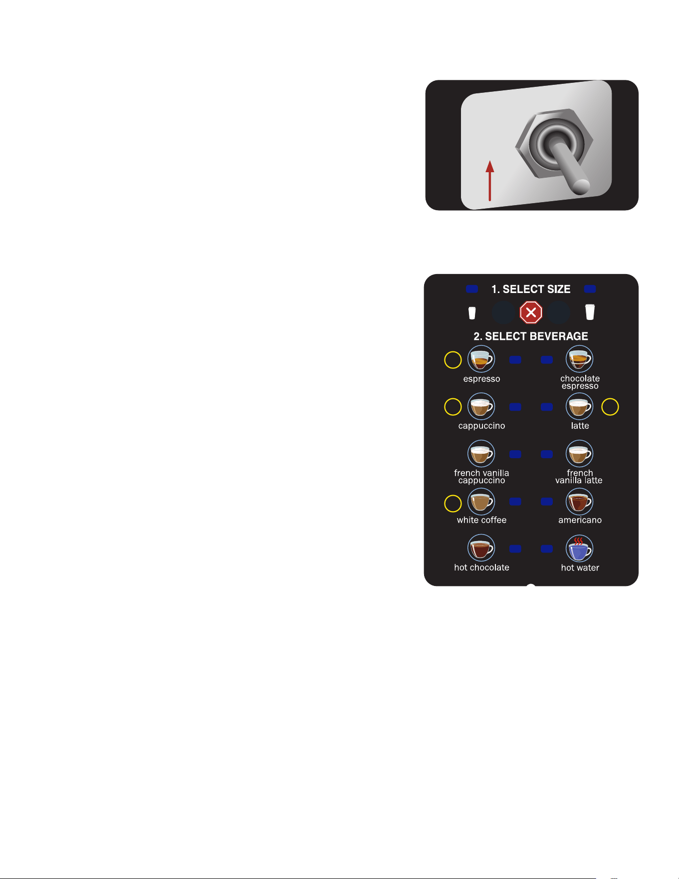
1. Open the door and place the NORMAL/PROGRAM/RINSE switch
in the PROGRAM position. (Figure 1)
2. Close the door and place a minimum two liter container
under the dispense nozzles.
3. Press the Large Cup button until the screen reads
DIAGNOSTICS.
4. Press, in sequence, buttons 3, 7, 4 and 1. See Figure 2 for
button number designations.
5. The screen will display SYSTEM WET TEST. Press the button
under YES.
6. Press the button under COOL ESP TANK.
7. Press the button under START in the COOL ESP TANK screen.
8. The pump will begin running, and hot water will dispense into
the container. After 4 minutes, the pump will automatically stop.
9. In the ESP TANK COOL? screen, press the button under YES.
NOTE: Dispenser must be OFF and disconnected from
the power source in steps 10 through 24.
10. Immediately turn OFF and disconnect the dispenser from the
power source, and water supply.
11. Let the water in the soluble tank cool before draining.
12. Remove left side panel.
13. Pull the drain tube out of the dispenser and direct it into a drain
or a container large enough to hold the volume of water in the
tank, approximately 6 liter (1.5 gallon).
14. Pinch tube and remove the plug from end of the tube.
15. After the tank has drained, replace the plug in the end of
the tube.
16. Remove the tube from the connector in the bottom of the
espresso tank.
17. Swivel the tube towards the outside of the machine.
18. Empty the container used to capture the hot water from the tank, and
place it on the right side of the machine.
19. Insert a 6mm OD tube into the espresso tank fitting, place the other
end into the container.
20. Use a 4mm hex wrench to loosen the plug on the top of the espresso
tank, until the tank begins to drain.
21. After the tank is drained, retighten the plug.
22. Remove the drain tube from the bottom tank fitting.
23. Rotate the fitting towards the inside of the tank. Compressing the
release sleeve on the fitting, fully insert the pump tube.
24. Replace the left and right side panels.
To be performed by qualified service personnel only!
DRAINING THE HOT WATER TANKS
NORMAL
PRGM
RINSE
32
1
5
10
10
1
5
15
1
4
1
10
5
1
1
4
1
+V
+V
-V
-V
GND
N/L2
L1
PS-1
POWER SUPPLY
24VDC, 150 WATTS
RED
GR AY
WHT
BLK
15
20
20
10
5
1
BEAN HOPPER
PHOTOSENSOR
10
1
5
1
5
1
5
10
1
5
15
20
10
1
5
RED
GR AY
1
1
RED
RED
1
2
4
3
1
1
RED
BLK
1
CURRENT
SENSOR
1
5
10
15
15 161
5
10
14
PUCK BIN
PROXIMITY
SENSOR
1
1
3
4
2
GRN
S1
S2
S3
S4
M1
REFILL VALVE
POWDER LEFT
POWER RIGHT
HOT WATER
HOPPER MTR LEFT
VIO VIO
ORN
YEL
WHT/GRN
RED
L1
BL/BK-16 WHT-16
N/L2
RED
RED
RED
BLK-16
J1
WHT/BLK
BLK
t-2
PNK
PROBE
LCD-1
LCD DISPLAY
50632.0000
MAIN CBA
GRN or GRN/YEL
K3
HEATER
SWITCHING
RELAY
RED
ORN
BLU
RED
GRN
ORN
BLU
WHT
WHT
BLK-16 WHT-16
K3
HEATER
SWITCHING
RELAY
H1 - POWDER TANK
H2-ESPRESSO TANK
WHT
WHT
t-1
ESP TANK
POWDER
TANK
NORMAL
PROGRAM
RINSE
BLK-16
BLU/BLK-16
WHT/YEL
YEL
WHT/GRN
WHT/GRN
YEL
WHT/YEL
M8
GRINDER
WHT
M3
HOPPER MTR RIGHT
S5
ESPRESSO WATER
K1
GRINDER RELAY
K2
PUMP RELAY
S6
SOLENOID PUMP
WHT
K3
HEATER SWITCHING
RELAY
FLW
FLOW
METER
K1
GRINDER
RELAY
K2
PUMP
RELAY
WHT
K4
HEATER
RELAY
SSR
K4
HEATER RELAY SSR
BG-1
ELDOM
ESPRESSO
GROUP HEAD
CSW-1
CAPACITIVE
TOUCH SWITCH
RED
RED
RED
RED
RED
RED
BLK-16
BLK BLK
BRN-16
M7
SOLUBLE FAN
RED
SW1
MASTER
ON/OFF
LT1
LT1
LT1
LT1
SW3
GRINDER
INTERRUPT
SWITCH
SW4
M2
HOPPER MTR MIDDLE
SW5
BLK
WHT
RED
GRN
BRN
BLU
ORN
YEL
VIO
GR AY
J18
J15
J17
J5
J24
J9
BLK
WHT
RED
GRN
BRN
BLU
ORN
YEL
VIO
GR AY
J26
RED
BLU
RED/BLK
BRN/WHT
RED
BRN/BLK
BLU/BLK
WHT/YEL
RED
WHT/VIO
WHT/RED
WHT/RED
WHT/GRN
RED
WHT/BLU
WHT/ORN
WHT/VIO
RED
GRN
BLK
WHT
GR AY
BLK
WHT/BLK
BLK
WHT/VIO
WHT/VIO
WHT/BLU
WHT/BLU
ORG
YEL
BLU
RED/BLK
BRN/WHT
BRN/BLK
BLU/BLK
WHT/YEL
WHT/GRN
BLK
RED
RED
RED
WHT/BLU
WHT/ORN
WHT/VIO
RED
GRN
BLK
GRN
SW2
DOOR
INTERRUPT
SWITCH
RED
BLK
YEL/GRN
M4
LEFT WHIPPER MOTOR
RED
WHT/BLK
M5
RIGHT WHIPPER MOTOR
RED
WHT/RED
RED
WHT/BLK
WHT/RED
RED
GRN
J23
BRN
BLK
BRN
BLK
J14
H11
CN1
GRN
BRN
ORN
YEL
BLU
VIO
GR AY
BLK
TAN
WHT
RED/BLK
PINK
WHT/BLK
WHT/RED
WHT/ORN
RED
GRN
BRN
ORN
YEL
BLU
VIO
GR AY
BLK
TAN
WHT
RED/BLK
PINK
WHT/BLK
W/R
W/O
WHT-16
WHT-16
BRN
BLU
BLK
BRN
BLU
BLU
BRN/BLK
MOTOR
CAPACITOR
BRN
BLU
CUP
LED
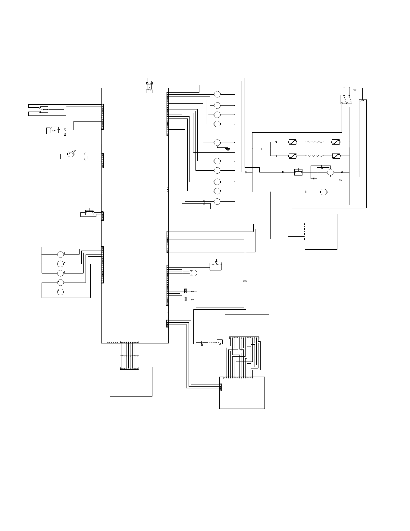
CRESCENDO
SCHEMATIC
120 VOLTS AC-2WIRE
SINGLE PHASE, 60HZ
OR
220-240 VOLTS AC-2WIRE
SINGLE PHASE, 50/60HZ
Artwork for P/N:54323.0000
Revision: B
Version: 01
Drawn: KJO
Date: 09/10/18
Colors:
Black
54323.0000 B 08/24/2018
© BUNN-O-Matic Corporation
1
5
10
10
1
5
15
1
4
1
10
5
1
1
4
1
+V
+V
-V
-V
GND
N/L2
L1
PS-1
POWER SUPPLY
24VDC, 150 WATTS
RED
GR AY
WHT
BLK
15
20
20
10
5
1
BEAN HOPPER
PHOTOSENSOR
10
1
5
1
5
1
5
10
1
5
15
20
10
1
5
RED
GR AY
1
1
RED
RED
1
2
4
3
1
1
RED
BLK
1
CURRENT
SENSOR
1
5
10
15
15 161
5
10
14
PUCK BIN
PROXIMITY
SENSOR
1
1
3
4
2
GRN
S1
S2
S3
S4
M1
REFILL VALVE
POWDER LEFT
POWER RIGHT
HOT WATER
HOPPER MTR LEFT
VIO VIO
ORN
YEL
WHT/GRN
RED
L1
BL/BK-16 WHT-16
N/L2
RED
RED
RED
BLK-16
J1
WHT/BLK
BLK
t-2
PNK
PROBE
LCD-1
LCD DISPLAY
50632.0000
MAIN CBA
GRN or GRN/YEL
K3
HEATER
SWITCHING
RELAY
RED
ORN
BLU
RED
GRN
ORN
BLU
WHT
WHT
BLK-16 WHT-16
K3
HEATER
SWITCHING
RELAY
H1 - POWDER TANK
H2-ESPRESSO TANK
WHT
WHT
t-1
ESP TANK
POWDER
TANK
NORMAL
PROGRAM
RINSE
BLK-16
BLU/BLK-16
WHT/YEL
YEL
WHT/GRN
WHT/GRN
YEL
WHT/YEL
M8
GRINDER
WHT
M3
HOPPER MTR RIGHT
S5
ESPRESSO WATER
K1
GRINDER RELAY
K2
PUMP RELAY
S6
SOLENOID PUMP
WHT
K3
HEATER SWITCHING
RELAY
FLW
FLOW
METER
K1
GRINDER
RELAY
K2
PUMP
RELAY
WHT
K4
HEATER
RELAY
SSR
K4
HEATER RELAY SSR
BG-1
ELDOM
ESPRESSO
GROUP HEAD
CSW-1
CAPACITIVE
TOUCH SWITCH
RED
RED
RED
RED
RED
RED
BLK-16
BLK BLK
BRN-16
M7
SOLUBLE FAN
RED
SW1
MASTER
ON/OFF
LT1
LT1
LT1
LT1
SW3
GRINDER
INTERRUPT
SWITCH
SW4
M2
HOPPER MTR MIDDLE
SW5
BLK
WHT
RED
GRN
BRN
BLU
ORN
YEL
VIO
GR AY
J18
J15
J17
J5
J24
J9
BLK
WHT
RED
GRN
BRN
BLU
ORN
YEL
VIO
GR AY
J26
RED
BLU
RED/BLK
BRN/WHT
RED
BRN/BLK
BLU/BLK
WHT/YEL
RED
WHT/VIO
WHT/RED
WHT/RED
WHT/GRN
RED
WHT/BLU
WHT/ORN
WHT/VIO
RED
GRN
BLK
WHT
GR AY
BLK
WHT/BLK
BLK
WHT/VIO
WHT/VIO
WHT/BLU
WHT/BLU
ORG
YEL
BLU
RED/BLK
BRN/WHT
BRN/BLK
BLU/BLK
WHT/YEL
WHT/GRN
BLK
RED
RED
RED
WHT/BLU
WHT/ORN
WHT/VIO
RED
GRN
BLK
GRN
SW2
DOOR
INTERRUPT
SWITCH
RED
BLK
YEL/GRN
M4
LEFT WHIPPER MOTOR
RED
WHT/BLK
M5
RIGHT WHIPPER MOTOR
RED
WHT/RED
RED
WHT/BLK
WHT/RED
RED
GRN
J23
BRN
BLK
BRN
BLK
J14
H11
CN1
GRN
BRN
ORN
YEL
BLU
VIO
GR AY
BLK
TAN
WHT
RED/BLK
PINK
WHT/BLK
WHT/RED
WHT/ORN
RED
GRN
BRN
ORN
YEL
BLU
VIO
GR AY
BLK
TAN
WHT
RED/BLK
PINK
WHT/BLK
W/R
W/O
WHT-16
WHT-16
BRN
BLU
BLK
BRN
BLU
BLU
BRN/BLK
MOTOR
CAPACITOR
BRN
BLU
CUP
LED
CRESCENDO
SCHEMATIC
120 VOLTS AC-2WIRE
SINGLE PHASE, 60HZ
OR
220-240 VOLTS AC-2WIRE
SINGLE PHASE, 50/60HZ
Artwork for P/N:54323.0000
Revision: B
Version: 01
Drawn: KJO
Date: 09/10/18
Colors:
Black
54323.0000 B 08/24/2018 © BUNN-O-Matic Corporation
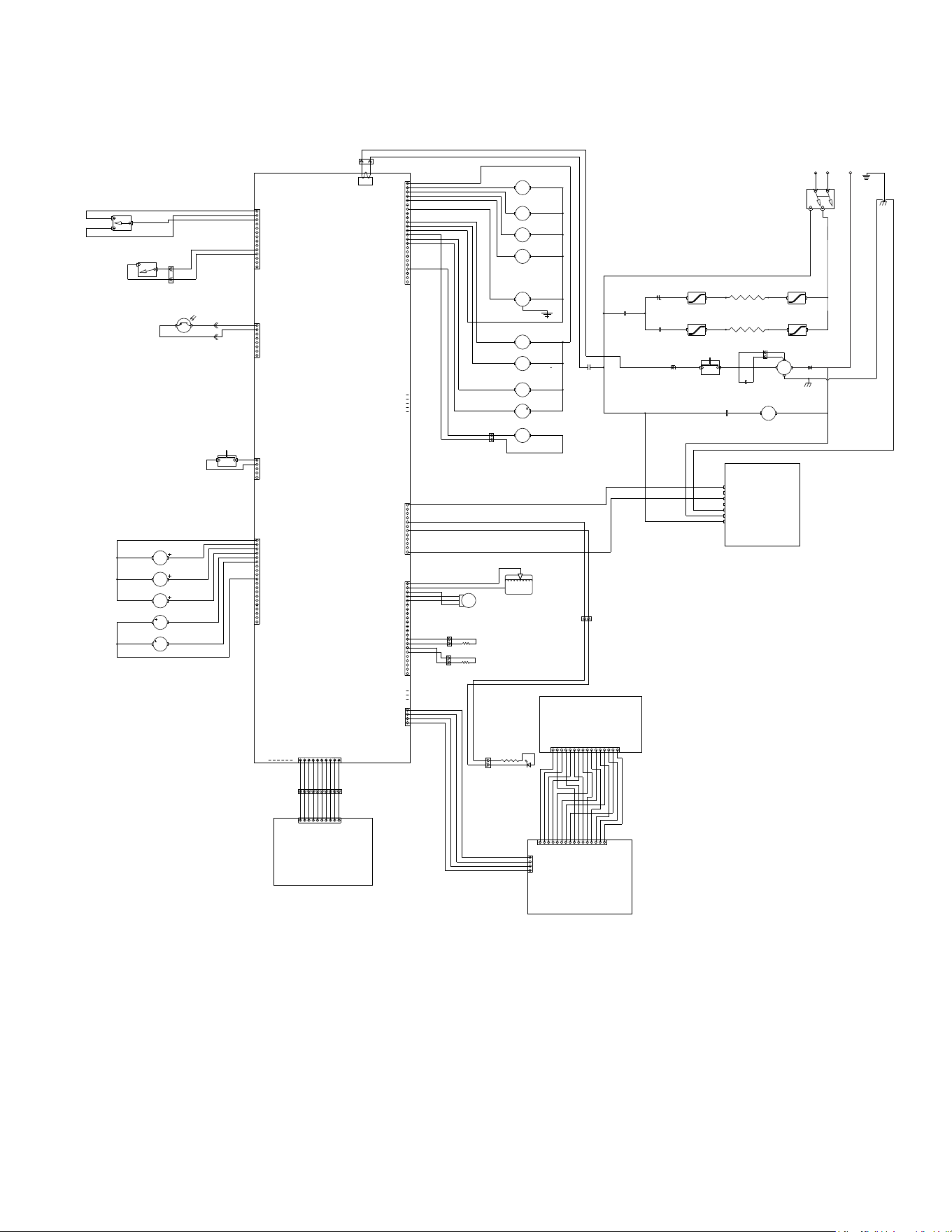
ELECTRICAL SCHEMATIC
33
1
5
10
10
1
5
15
1
4
1
10
5
1
1
4
1
+V
+V
-V
-V
GND
N/L2
L1
PS-1
POWER SUPPLY
24VDC, 150 WATTS
RED
GR AY
WHT
BLK
15
20
20
10
5
1
BEAN HOPPER
PHOTOSENSOR
10
1
5
1
5
1
5
10
1
5
15
20
10
1
5
RED
GR AY
1
1
RED
RED
1
2
4
3
1
1
RED
BLK
1
CURRENT
SENSOR
1
5
10
15
15 161
5
10
14
PUCK BIN
PROXIMITY
SENSOR
1
1
3
4
2
GRN
S1
S2
S3
S4
M1
REFILL VALVE
POWDER LEFT
POWER RIGHT
HOT WATER
HOPPER MTR LEFT
VIO VIO
ORN
YEL
WHT/GRN
RED
L1 L2
BL/BK-16 RED-16
N
RED
RED
RED
BLK-16
J1
WHT/BLK
BLK
t-2
PNK
PROBE
LCD-1
LCD DISPLAY
50632.0000
MAIN CBA
GRN
K3
HEATER
SWITCHING
RELAY
RED
ORN
BLU
RED
GRN
ORN
BLU
WHT
WHT
BLK-16 RED-16
K3
HEATER
SWITCHING
RELAY
H1 - POWDER TANK
H2-ESPRESSO TANK
WHT
WHT
t-1
ESP TANK
POWDER
TANK
NORMAL
PROGRAM
RINSE
BLK-16
BLU/BLK-16
WHT/YEL
YEL
WHT/GRN
WHT/GRN
YEL
WHT/YEL
M8
GRINDER
WHT
M3
HOPPER MTR RIGHT
S5
ESPRESSO WATER
K1
GRINDER RELAY
K2
PUMP RELAY
S6
SOLENOID PUMP
WHT
K3
HEATER SWITCHING
RELAY
FLW
FLOW
METER
K1
GRINDER
RELAY
K2
PUMP
RELAY
WHT
K4
HEATER
RELAY
SSR
K4
HEATER RELAY SSR
BG-1
ELDOM
ESPRESSO
GROUP HEAD
CSW-1
CAPACITIVE
TOUCH SWITCH
RED
RED
RED
RED
RED
RED
BLK-16
BLK BLK
BRN-16
M7
SOLUBLE FAN
RED
SW1
MASTER
ON/OFF
LT1
LT1
LT1
LT1
SW3
GRINDER
INTERRUPT
SWITCH
SW4
M2
HOPPER MTR MIDDLE
SW5
BLK
WHT
RED
GRN
BRN
BLU
ORN
YEL
VIO
GR AY
J18
J15
J17
J5
J24
J9
BLK
WHT
RED
GRN
BRN
BLU
ORN
YEL
VIO
GR AY
J26
RED
BLU
RED/BLK
BRN/WHT
RED
BRN/BLK
BLU/BLK
WHT/YEL
RED
WHT/VIO
WHT/RED
WHT/RED
WHT/GRN
RED
WHT/BLU
WHT/ORN
WHT/VIO
RED
GRN
BLK
WHT
GR AY
BLK
WHT/BLK
BLK
WHT/VIO
WHT/VIO
WHT/BLU
WHT/BLU
ORG
YEL
BLU
RED/BLK
BRN/WHT
BRN/BLK
BLU/BLK
WHT/YEL
WHT/GRN
BLK
RED
RED
RED
WHT/BLU
WHT/ORN
WHT/VIO
RED
GRN
BLK
GRN
SW2
DOOR
INTERRUPT
SWITCH
RED
BLK
YEL/GRN
M4
LEFT WHIPPER MOTOR
RED
WHT/BLK
M5
RIGHT WHIPPER MOTOR
RED
WHT/RED
RED
WHT/BLK
WHT/RED
RED
GRN
J23
BRN
BLK
BRN
BLK
J14
H11
CN1
GRN
BRN
ORN
YEL
BLU
VIO
GR AY
BLK
TAN
WHT
RED/BLK
PINK
WHT/BLK
WHT/RED
WHT/ORN
RED
GRN
BRN
ORN
YEL
BLU
VIO
GR AY
BLK
TAN
WHT
RED/BLK
PINK
WHT/BLK
W/R
W/O
BL/BK-16
BL/BK-16
BRN
BLU
BLK
BRN
BLU
BLU
BRN/BLK
MOTOR
CAPACITOR
BRN
BLU
CUP
LED
CRESCENDO
SCHEMATIC
120/208 - 240 VOLTS AC-3WIRE
SINGLE PHASE, 60HZ
Artwork for P/N:54323.0001
Revision: A
Version: 00
Drawn: KJO
Date: 08/24/18
Colors:
Black
54323.0001 A 08/24/2018
© BUNN-O-Matic Corporation
1
5
10
10
1
5
15
1
4
1
10
5
1
1
4
1
+V
+V
-V
-V
GND
N/L2
L1
PS-1
POWER SUPPLY
24VDC, 150 WATTS
RED
GR AY
WHT
BLK
15
20
20
10
5
1
BEAN HOPPER
PHOTOSENSOR
10
1
5
1
5
1
5
10
1
5
15
20
10
1
5
RED
GR AY
1
1
RED
RED
1
2
4
3
1
1
RED
BLK
1
CURRENT
SENSOR
1
5
10
15
15 161
5
10
14
PUCK BIN
PROXIMITY
SENSOR
1
1
3
4
2
GRN
S1
S2
S3
S4
M1
REFILL VALVE
POWDER LEFT
POWER RIGHT
HOT WATER
HOPPER MTR LEFT
VIO VIO
ORN
YEL
WHT/GRN
RED
L1 L2
BL/BK-16 RED-16
N
RED
RED
RED
BLK-16
J1
WHT/BLK
BLK
t-2
PNK
PROBE
LCD-1
LCD DISPLAY
50632.0000
MAIN CBA
GRN
K3
HEATER
SWITCHING
RELAY
RED
ORN
BLU
RED
GRN
ORN
BLU
WHT
WHT
BLK-16 RED-16
K3
HEATER
SWITCHING
RELAY
H1 - POWDER TANK
H2-ESPRESSO TANK
WHT
WHT
t-1
ESP TANK
POWDER
TANK
NORMAL
PROGRAM
RINSE
BLK-16
BLU/BLK-16
WHT/YEL
YEL
WHT/GRN
WHT/GRN
YEL
WHT/YEL
M8
GRINDER
WHT
M3
HOPPER MTR RIGHT
S5
ESPRESSO WATER
K1
GRINDER RELAY
K2
PUMP RELAY
S6
SOLENOID PUMP
WHT
K3
HEATER SWITCHING
RELAY
FLW
FLOW
METER
K1
GRINDER
RELAY
K2
PUMP
RELAY
WHT
K4
HEATER
RELAY
SSR
K4
HEATER RELAY SSR
BG-1
ELDOM
ESPRESSO
GROUP HEAD
CSW-1
CAPACITIVE
TOUCH SWITCH
RED
RED
RED
RED
RED
RED
BLK-16
BLK BLK
BRN-16
M7
SOLUBLE FAN
RED
SW1
MASTER
ON/OFF
LT1
LT1
LT1
LT1
SW3
GRINDER
INTERRUPT
SWITCH
SW4
M2
HOPPER MTR MIDDLE
SW5
BLK
WHT
RED
GRN
BRN
BLU
ORN
YEL
VIO
GR AY
J18
J15
J17
J5
J24
J9
BLK
WHT
RED
GRN
BRN
BLU
ORN
YEL
VIO
GR AY
J26
RED
BLU
RED/BLK
BRN/WHT
RED
BRN/BLK
BLU/BLK
WHT/YEL
RED
WHT/VIO
WHT/RED
WHT/RED
WHT/GRN
RED
WHT/BLU
WHT/ORN
WHT/VIO
RED
GRN
BLK
WHT
GR AY
BLK
WHT/BLK
BLK
WHT/VIO
WHT/VIO
WHT/BLU
WHT/BLU
ORG
YEL
BLU
RED/BLK
BRN/WHT
BRN/BLK
BLU/BLK
WHT/YEL
WHT/GRN
BLK
RED
RED
RED
WHT/BLU
WHT/ORN
WHT/VIO
RED
GRN
BLK
GRN
SW2
DOOR
INTERRUPT
SWITCH
RED
BLK
YEL/GRN
M4
LEFT WHIPPER MOTOR
RED
WHT/BLK
M5
RIGHT WHIPPER MOTOR
RED
WHT/RED
RED
WHT/BLK
WHT/RED
RED
GRN
J23
BRN
BLK
BRN
BLK
J14
H11
CN1
GRN
BRN
ORN
YEL
BLU
VIO
GR AY
BLK
TAN
WHT
RED/BLK
PINK
WHT/BLK
WHT/RED
WHT/ORN
RED
GRN
BRN
ORN
YEL
BLU
VIO
GR AY
BLK
TAN
WHT
RED/BLK
PINK
WHT/BLK
W/R
W/O
BL/BK-16
BL/BK-16
BRN
BLU
BLK
BRN
BLU
BLU
BRN/BLK
MOTOR
CAPACITOR
BRN
BLU
CUP
LED
CRESCENDO
SCHEMATIC
120/208 - 240 VOLTS AC-3WIRE
SINGLE PHASE, 60HZ
Artwork for P/N:54323.0001
Revision: A
Version: 00
Drawn: KJO
Date: 08/24/18
Colors:
Black
54323.0001 A 08/24/2018 © BUNN-O-Matic Corporation
ELECTRICAL SCHEMATIC