1
User Manual
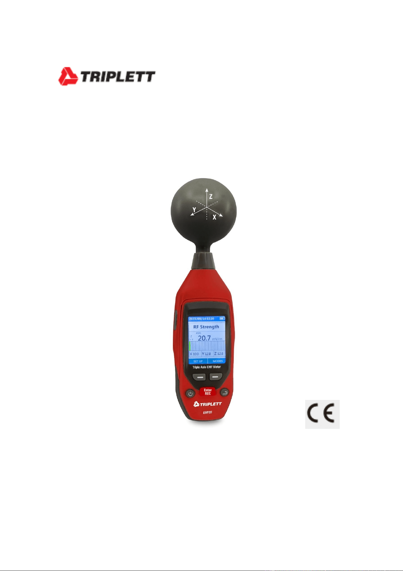
EMF85
Triple Axis EMF Meter

2
Introduction
Electromagnetic Pollution: Electromagnetic pollution refers to the interference of natural and
man-made electromagnetic waves and harmful electromagnetic radiation. Due to the
development of radio, television, and microwave technology, the power of radio frequency
equipment has doubled, leading to increased electromagnetic radiation posing a direct threat to
human health. Excessive electromagnetic radiation causes electromagnetic pollution.
Electric Field Intensity (E): A vector field in which charge feels the force constitutes the electric
field. The strength of the electric field at any point is defined as the force exerted on the unit of
positive charge at that point, measured in volts per meter (V/m).
Magnetic Field Intensity (H): Similar to the electric field, it is a vector field where charge feels the
force. Measured in volts per meter (V/m).
Power Density (S): The power per unit area on the vertical plane of the direction of propagation
of an electromagnetic field, often measured in watts per square meter (W/m) or milliwatts per
square centimeter (mW/cm²).
Electromagnetic Field Characteristic (S): The electromagnetic field propagates as a wave and
travels at the speed of light (c). The wavelength (λ) is inversely proportional to frequency (f). If
the distance source is less than 3 wavelengths, it is considered to be in the near-field region; if
greater, it's in the far-field region.
1-2 Application
The RF Electromagnetic Wave Tester is used in areas with emitted electromagnetic fields, such as
radio stations. It's crucial to avoid hazardous levels of electromagnetic radiation. National and
international regulations provide allowable power density limits for different frequency ranges
and signal forms.
1-3 Features
This table is designed for wide-band monitoring of high-frequency radiation (50MHz to 8G). It
provides non-directional electric field testing with high sensitivity, measuring electric and
magnetic field strength. It displays results in terms of electric field intensity and power density.
3
This table can be set to display the average measured value and the maximum average measured
value.The maximum average measurement can be used as a directional test, for example when
entering an exposed area for the first time.
Detect the frequency range of 50MHz to 8GHz.
Isodirectional electromagnetic field measurement.
Nondirectional measurements look at the triaxes and measurements.
High dynamic range view XYZ direction measurements.
Programmable alarm limit and storage function.
Overload display OL.
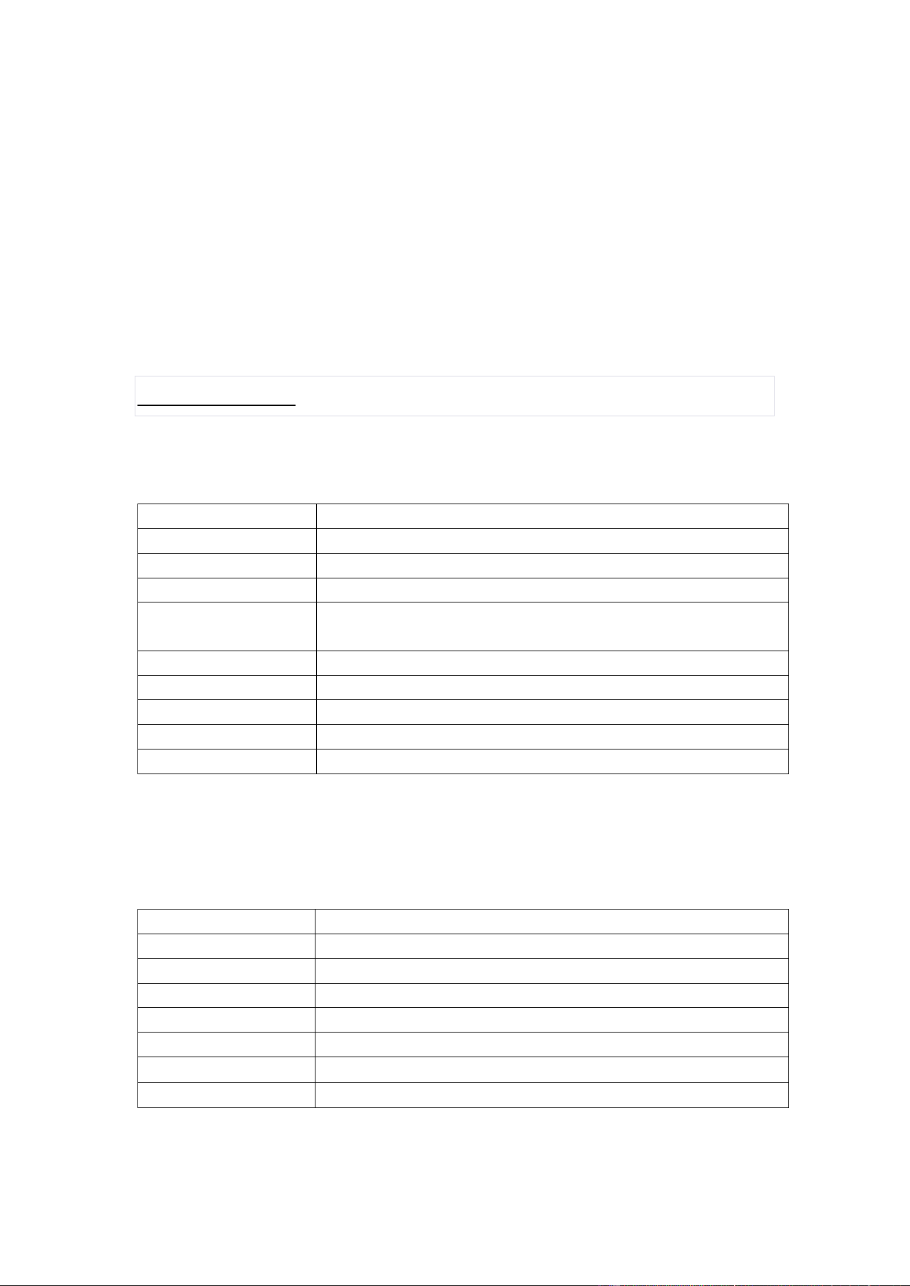
Specifications
2-1 General specifications
Measurement method
Digital display、Three axis measurement
Measuring gear
A continuous gear
reaction time
1s
Sound warning
Buzzer
unit
uW/m², mW/m², W/m², uW/cm², mW/cm², mV/m ,
V/m
Display value
Average maximum average
Operating temperature
0℃ ~ 50℃
Operating humidity
0% ~ 75%RH
Storage temperature
-10℃ ~ 60℃
Storage humidity
0% ~ 80%RH
2-2 Electrical specifications
Directivity characteristic
Isotropic. three-axis
Measuring mode
High frequency electric field
Display resolution
0.1mV/m 0.1uW/m2 0.001uW/cm2
Frequency range
50MHz~8GHz
Measuring range
1uW/m²~26.52W/m²,0uW/cm²~2.652mW/cm², 20mV/m~100V/m
Dynamic range
45dB
Frequency response
±1.0dB(50MHz to 1.9GHz),±2.4dB(1.9GHz to 8GHz)
Overload limit
2.652mW/cm²(100V/m)
4
三、Operating instructions
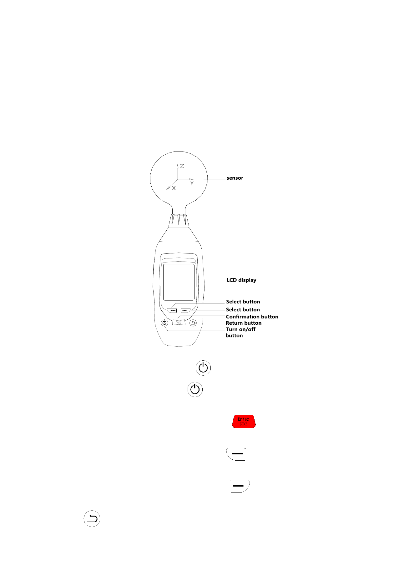
3-1 Front panel and button description
(1).If the power off, press and hold button, until the LCD is on, then the unit will
power on.If the power on, press and hold button, until the LCD is off then the unit will
power off.
(2). In the state of the main interface, long press the button to enter the interface of
historical data saving(If you've saved the data)。
(3). Under the state of the main interface, press the button to enter the menu
selection interface.
(4). Under the state of the main interface, press the button to enter the data saving
interface.
(5). is the back button.
5
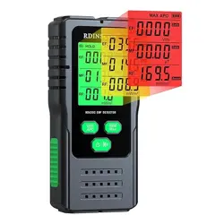
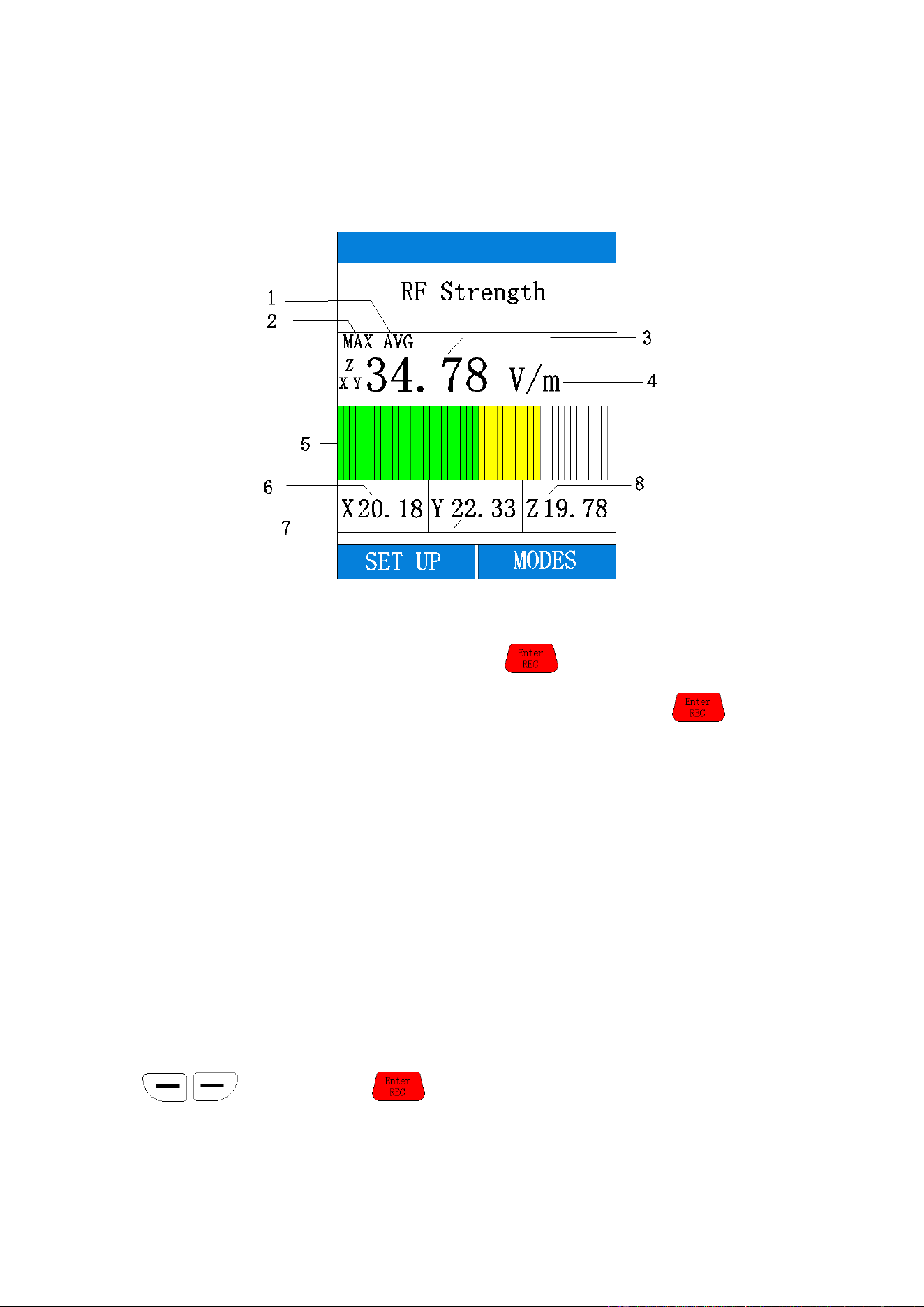
3-2 Main interface display content description
1. Represents the average measured value.
2. Represents the maximum average measured value.The initial interface only displays AVG, and
the displayed value is the average value. Press the button, and MAX AVG will be
displayed, and the displayed value is the maximum average value. Pressing the button
again will switch to display the average value.
3. Represents the average value of X.Y.Z triaxial composite
4. Denotes a unit of measurement.mV/m, V/m(Electric field intensity) uW/m²,mW/m²,W/m²
uWcm²,mW/cm²(Power density)
5. Degree representation of triaxial composite value.
6. X-axis direction value.
7. Y-axis direction value.
8. Z-axis direction value.
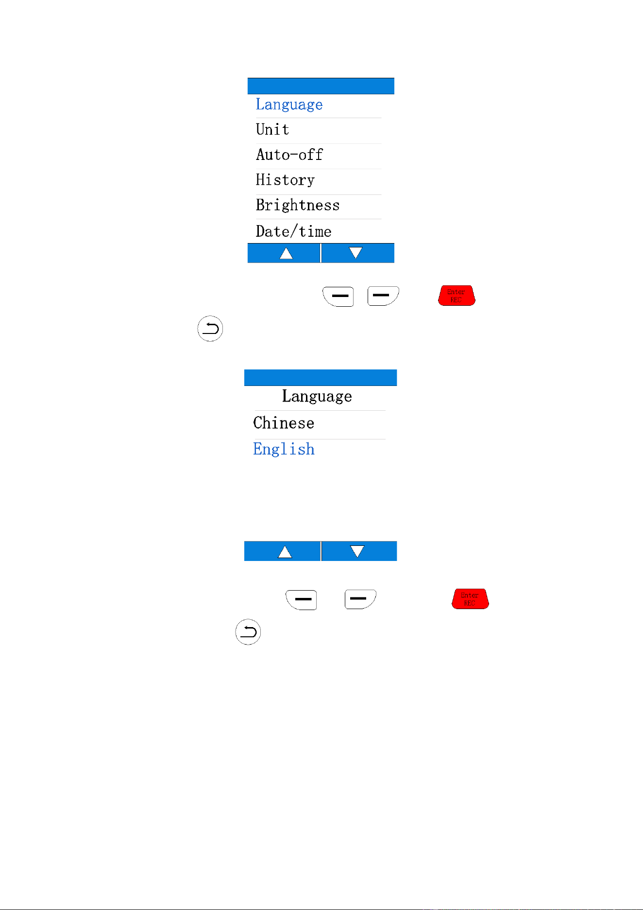
3-3 Menu
Press the "SET UP" button to enter the menu Settings interface.Eight set a "Language", "Unit",
"Auto-off", "History", "brightness", "Date/time", "Alarm", "Calibration".Select and switch by
button and press button to enter the corresponding Settings.
6
(1)Language
Select the language you want to display by or , press to confirm
the selection or press to exit the selection.
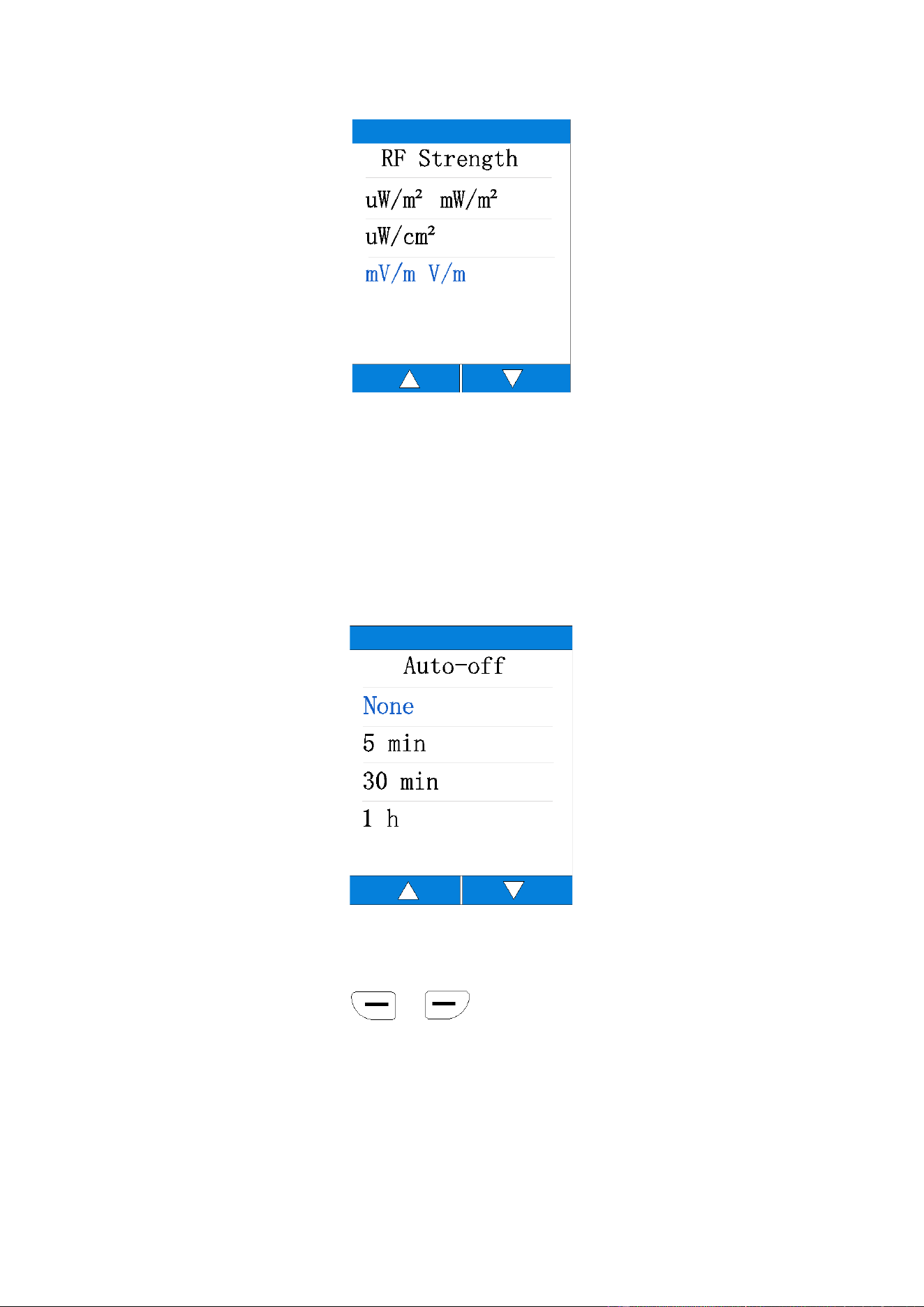
(2)Unit
Select the unit to be changed by or button, press button to
confirm the selection or press button to exit the selection.
7
(3)Auto-off
This option is used to set the automatic shutdown time of the device.There are 5 minutes,
30 minutes and 1 hour to choose from.If no button is pressed within the automatic shutdown
time range, the device will automatically shut down.Select "None" and the device will continue to
work until the low power shutdown occurs.
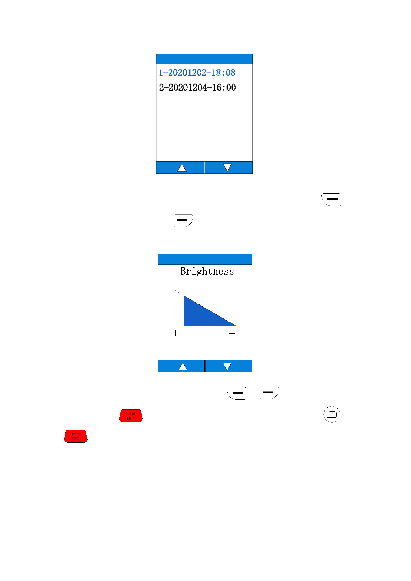
(4)History
This option is used to view the device's historical data.The data are arranged in record order,
listing the record time.Press the or buttons to select the data you want to view The
saved data is stored on the device and can be viewed through a history page or opened on the
computer via USB.All records are separated into CSV files based on different dates.Each CSV file
contains all the records for each day.
8
(5)Brightness
This option is used to set screen brightness and has four brightness levels.Press the
button to increase brightness and the button to reduce brightness.
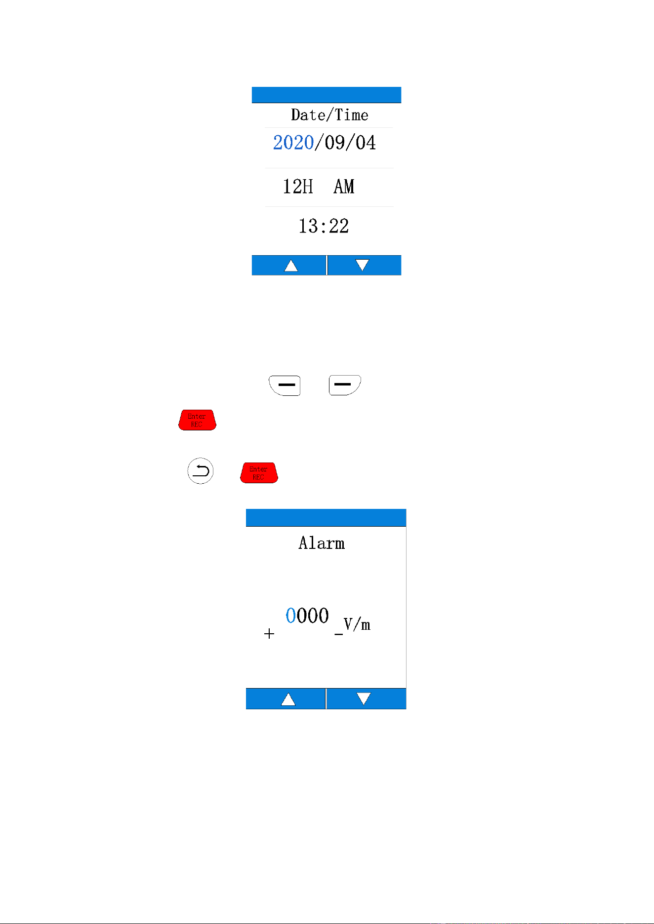
(6) Date/time
After entering the time/date setting mode, press or button to adjust the set
value, and press button to set the next value.After setting, please press or
button to exit the time/date setting mode and return to the system setting interface.
9
(7)Alarm
This option is used to set alarm related Settings.If you enter the alarm setting, you can choose
to turn it on or off. If you choose to turn it off, you will exit the alarm setting interface and return
to the system setting interface.Select the alarm function to enter the alarm setting interface. The
setting value can be adjusted by or button. The minimum setting value is
1V/m.Press the button to select digit values.The set alarm value will be compared with
the X.Y.Z. triaxial composite value. A continuous beeping alarm will occur if the value is greater than
the set value.Press
or to exit the alarm setting after completing the setting.
Tip: This function needs to be set in V/ M units.

11
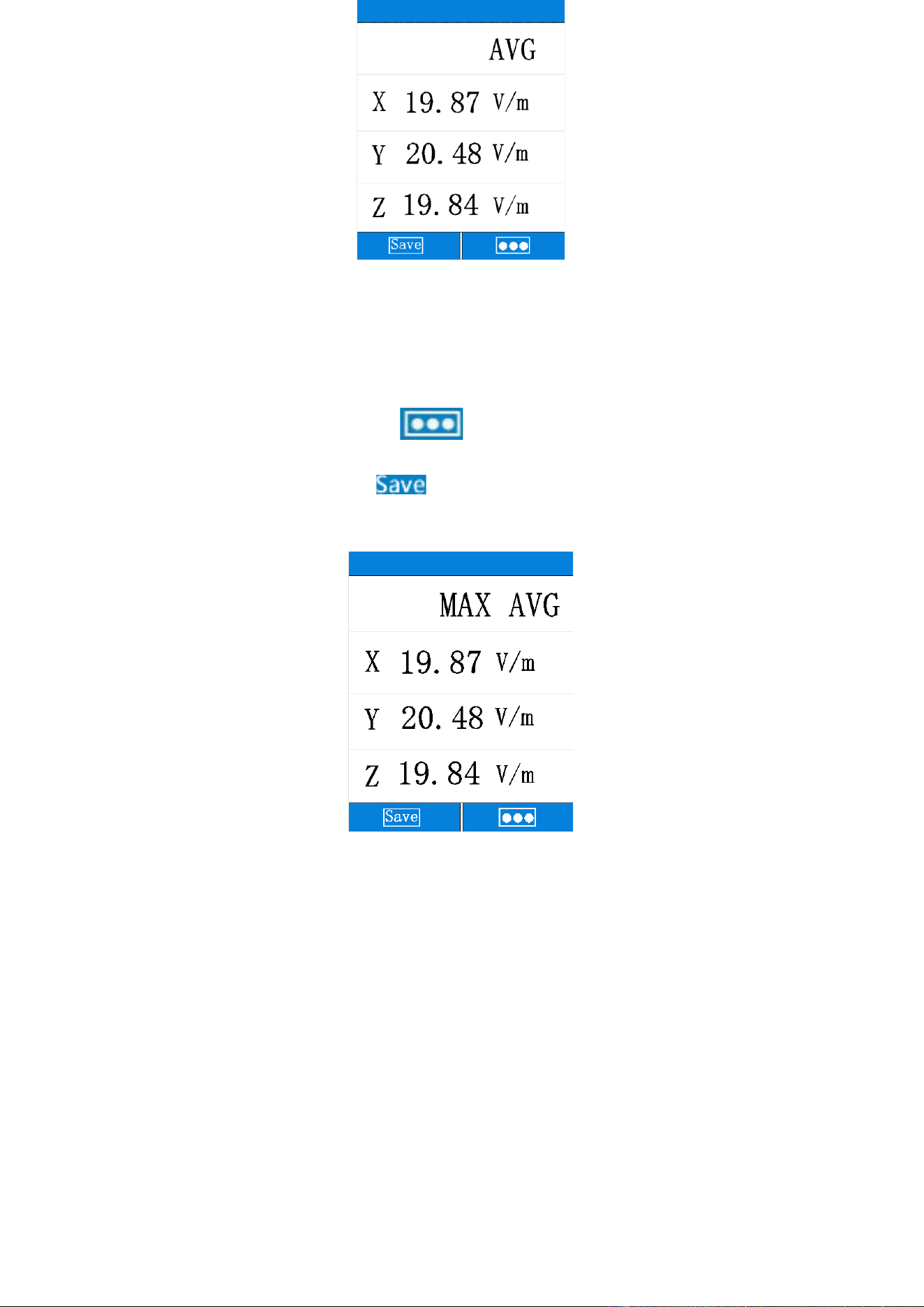
3-4Data saving
(1)AVG mode
Press the "Mode" button in the main interface to enter the data saving interface.
In AVG mode, the device calculates the average data showing the X,Y, and Z axes.
Users can press the
function button on the left to save the current measurement
results.
12
(2)MAX AVG mode
In AVG mode, users can press the
function button on the right to switch to MAX
AVG mode.In MAX AVG mode, the device calculates the maximum average data showing the X,Y,
and Z axes.Users can press the function button on the left to save the current
measurement results.The saved data can be viewed in the data record or on the computer via USB
when the device is turned off.
Measurement instructions
4-1 All electric field intensity meters should pay attention
to the following effects
If a fast-moving electric field sensor displays a large electric field intensity value, the display
value does not represent the actual electric field intensity, which is caused by electrostatic
discharge.
13
Suggestion: Stabilize the table when measuring.
4-2 Short time measurement
Maximum mode is used to determine the characteristics and direction of the unknown field
when entering an electromagnetic field exposure area.It is very important to take several
measurements at different locations around the area you want to measure, if you know nothing
about the field.Pay special attention to making some measurements of nearby potential sources
of radiation.Components other than radiation sources also emit electromagnetic fields.For
example, electrical cables used in current diathermy medical devices may also emit
electromagnetic energy, so the maximum electric field intensity at the operating position is found
in the area adjacent to the knee.Note that metallic objects in the field area may concentrate or
amplify the field from a source of radiation at a distance.
4-3 Long time measurement
Place this meter between your work position and the possible source of radiation, and take
measurements at your body's closest point to the source.
You can fix the watch on a board.
4-4 Safety instructions for measurement
In some cases, working near powerful sources of radiation can be life-threatening.
Note that secondary radiation (such as metal wall reflectors) can amplify the electric field.
Note that the intensity of the electric field near the source increases inversely to the third
power of the distance, so that large current intensities are immediately felt near small sources
(e.g. waveguide leakage, induction furnace).
When the spectral component of the electric field goes beyond this frequency range, it will
generally produce incorrect assessment and tends to be underestimated. Therefore, before using
the electric field strength tester, it should be determined that all its measured components are
within the frequency range specified by the meter.