


Table of Contents
WWasher Dimensionsasher Dimensions ............................................................................................................................................................................................................................................44
InstallationInstallation..........................................................................................................................................................................................................................................................................55
Before You Start......................................................................................................................................5
Supplies................................................................................................................................................5
Parts Included.......................................................................................................................................5
Parts Needed ........................................................................................................................................5
Order of Installation Steps ...................................................................................................................5
Remove the Shipping Brace and Shipping Plug .....................................................................................5
Wipe Out Inside of Washtub ...................................................................................................................6
Connect Fill Hoses ..................................................................................................................................6
Water Supply Requirements ................................................................................................................6
Connecting Hoses ................................................................................................................................7
Connect Drain Hose to Drain Receptacle ...............................................................................................7
Standpipe Installation...........................................................................................................................7
Low Standpipe Installation ..................................................................................................................8
Wall Installation ...................................................................................................................................8
Laundry Tub Installation......................................................................................................................8
Position and Level the Washer................................................................................................................9
Plug In the Washer ..................................................................................................................................9
Electrical Requirements .......................................................................................................................9
Earth/Ground Instructions..................................................................................................................10
Check Lid Lock..................................................................................................................................... 11
Check Installation.................................................................................................................................. 11
Installer ChecklistInstaller Checklist ..............................................................................................................................................................................................................................................1212
© Copyright 2025, Alliance Laundry Systems LLC
All rights reserved. No part of the contents of this book may be reproduced or transmitted in any form or by any means without the expressed written
consent of the publisher.
© Copyright, Alliance Laundry Systems LLC -
3 Part No. 204104ENR5
continues...
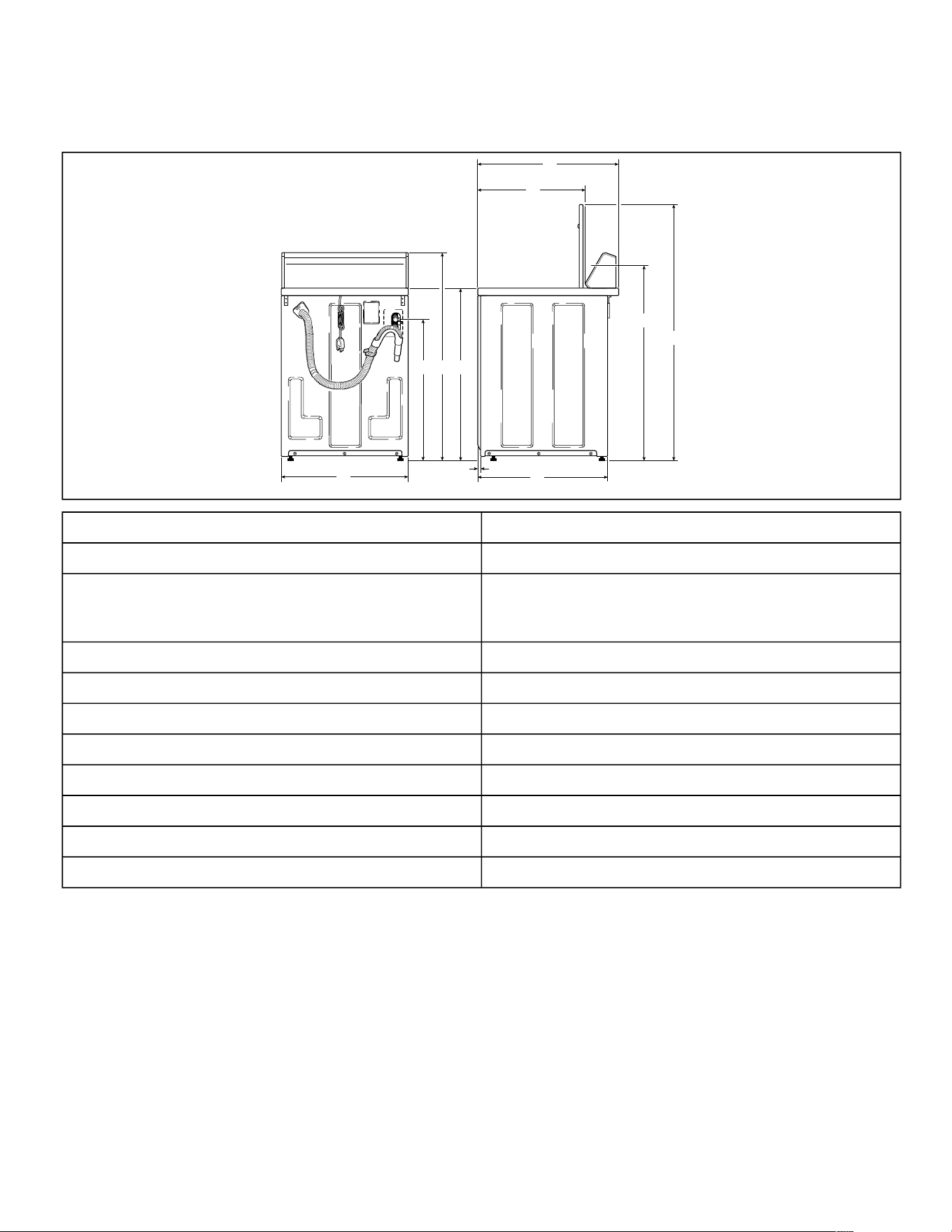
Dimensions and Specifications
TLW2340N_SVG
JI
H
G
F
E
D
C
B
A
A 28 in. [711 mm]
B 22.13 in. [562 mm]
C (to controls)
Electronic Control: * 41.25 in. [1048 mm]
Knob Control: * 40.75 [1035 mm]
D * 53 in. [1346 mm]
E 26 in. [660 mm]
F 0.4 in. [10 mm]
G 25.63 in. [651 mm]
H * 29 in. [737 mm]
I * 42.75 in. [1086 mm]
J * 36 in. [914 mm]
*With leveling legs turned into base.
Dimensions and Specifications
© Copyright, Alliance Laundry Systems LLC -
DO NOT COPY or TRANSMIT
4 Part No. 204104ENR5
Installation
Before You Start
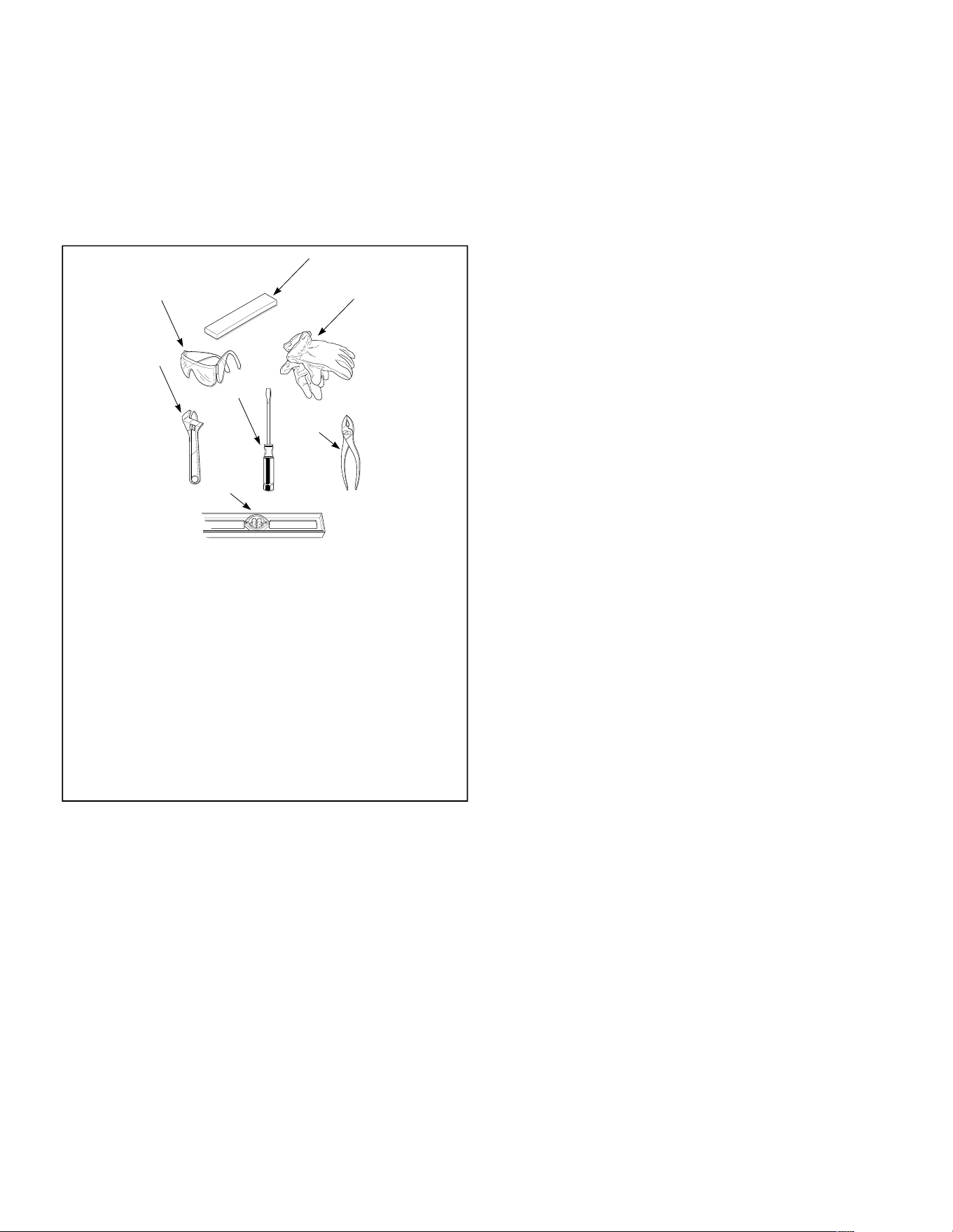
Supplies
For most installations, the basic supplies you will need are:
TLW2218N_SVG
3
4
5
6
7
2
1
1. Safety Glasses
2. Wood Block
3. Gloves
4. Wrench
5. Screwdriver
6. Pliers
7. Level
NOTE: A cloth rag and all-purpose cleaner are also
needed.
Figure 1
NOTE: If the washer is delivered on a cold day (below
freezing), or is stored in an unheated room or area
during the cold months, do not attempt to operate it
until the washer has had a chance to warm up.
NOTE: Install dryer before washer. This allows room
for attaching exhaust duct.
NOTE: This appliance is suitable for use in countries
having a warm, damp climate.
Parts Included
An accessories bag has been shipped inside your washer. It in-
cludes:
• Two filter screen washers
• Two plain rubber washers
• Four rubber feet
• Beaded strap
• Product literature
Parts Needed
Two fill hoses are required for installation. Order 205746
Washer Hose Connection Kit if needed.
If using any other hoses, follow these requirements:
• Hoses must be new.
• Hoses must be a minimum of 3/8 in. inside diameter. Smaller
inside diameter hoses will cause long fill times which could
create nuisance fill errors.
• The two plain rubber washers and two filter screens included
with the washer in the accessories bag must be installed in
the fill hose couplings. Refer to
Connect Fill Hoses
. The fil-
ter screens help prevent foreign materials from clogging the
water mixing valve.
Order of Installation Steps
The proper order of steps must be followed to ensure correct
installation. Refer to the list below when installing your unit.
1. Put on safety glasses and gloves.
2. Remove the shipping brace and shipping plug.
3. Wipe out inside of the washer.
4. Connect the fill hoses.
5. Connect the drain hose to the drain receptacle.
6. Position and level the washer.
7. Plug in the washer.
8. Check the lid lock.
9. Check installation.
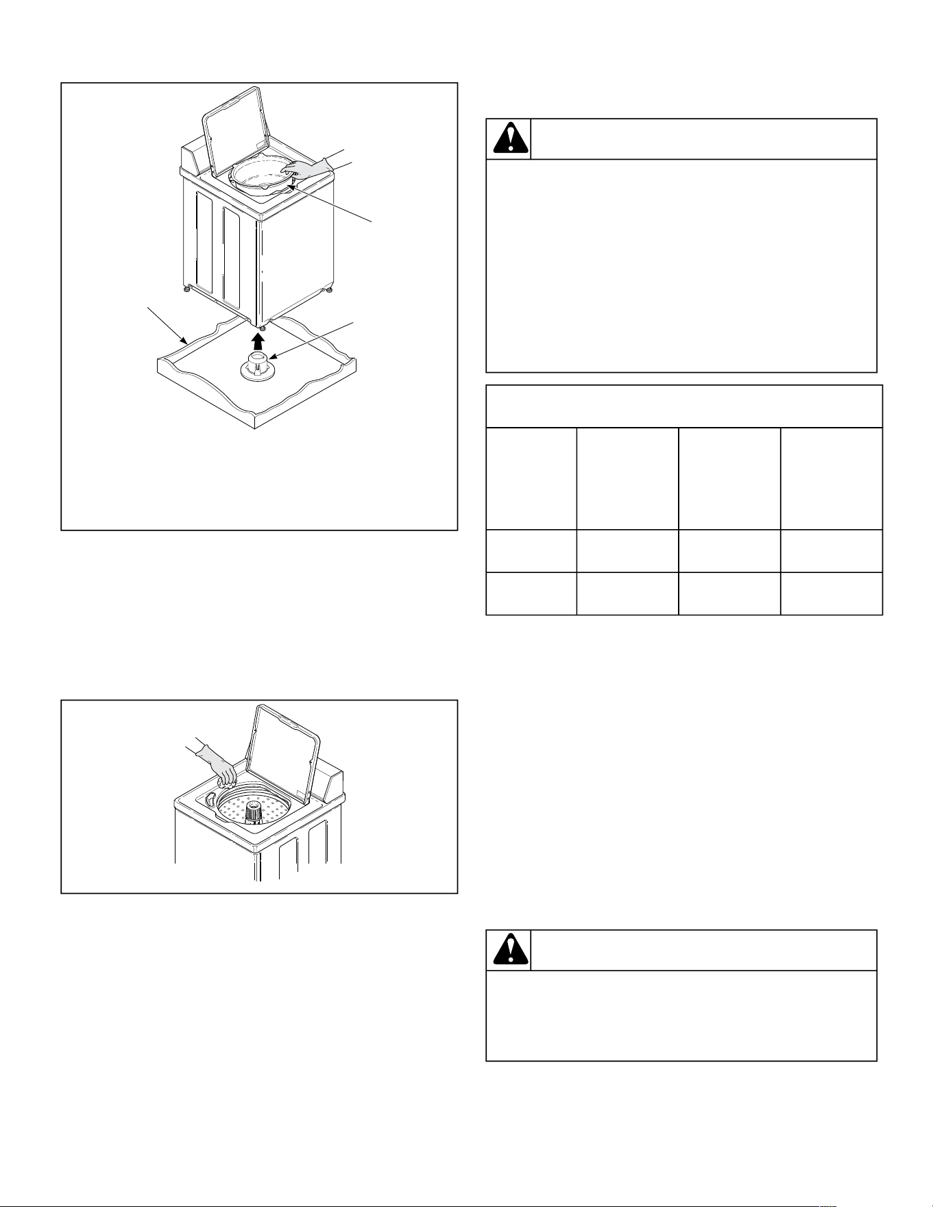
Remove the Shipping Brace and
Shipping Plug
1. Remove the shipping brace from under the lid.
2. The shipping plug will be released from the base of the wash-
er when removing the cardboard base from the washer.
The shipping brace and plug should be saved and must be
reinstalled whenever washer is moved or transported to a
new location. This will prevent damage to washer compo-
nents.
Do not tilt washer to front or sides when moving.
Refer to the User's Guide for instructions on reinstalling the
shipping materials.
Installation
© Copyright, Alliance Laundry Systems LLC -
DO NOT COPY or TRANSMIT
5 Part No. 204104ENR5
continues...
TLW2280N_SVG
2
1
3
1. Shipping Brace
2. Shipping Plug
3. Cardboard Base
Figure 2
Wipe Out Inside of Washtub
1. Prior to first wash, use an all purpose cleaner or a detergent
and water solution and a damp cloth to remove shipping dust
from inside of washtub.
TLW2281N_SVG
Figure 3
Connect Fill Hoses
WARNING
Under certain conditions, hydrogen gas may be
produced in a hot water system that has not been
used for two weeks or more. HYDROGEN GAS IS
EXPLOSIVE. If the hot water system has not been
used for such a period and before using the
washer, turn on all hot water faucets and let the
water flow from each for several minutes. This will
release any accumulated hydrogen gas. The gas is
flammable. Do not smoke or use an open flame
during this time.
W029
Mixing Valve Flow Rates
Pressure
psi [kPa]
HOT
gallons per
minute [liters
per minute]
COLD
gallons per
minute [liters
per minute]
WARM
gallons per
minute [liters
per minute]
20 [138] 3.4 [12.9] 3.4 [12.9] 4.0 [15.1]
120 [827] 4.6 [17.4] 4.6 [17.4] 4.6 [17.4]
Water Supply Requirements
Water supply faucets must fit standard 3/4 inch [19 mm] fe-
male garden hose couplings. DO NOT USE SLIP-ON OR
CLAMP-ON CONNECTIONS.
NOTE: Water supply faucets should be readily acces-
sible to permit turning them off when washer is not
being used.
Recommended cold water temperature is 50° to 75° Fahrenheit
[10° to 24° Celsius] . Recommended maximum hot water tem-
perature is 125° Fahrenheit [51° Celsius] . Warm water is a
mixture of hot and cold water. Warm water temperature is de-
pendent upon the water temperature and the pressure of both
the hot and cold water supply lines.
WARNING
To prevent personal injury, avoid contact with inlet
water temperatures higher than 125° Fahrenheit [51°
Celsius] and hot surfaces.
W748
Water pressure must be a minimum of 20 to a maximum of
120 pounds per square inch [minimum of 138 to a maximum
Installation
© Copyright, Alliance Laundry Systems LLC -
DO NOT COPY or TRANSMIT
6 Part No. 204104ENR5
of 827 kPa] static pressure measured at the faucet.
NOTE: Water pressure under 20 pounds per square
inch [138 kPa] will cause an extended fill time in the
washer.
Turn on the water supply faucets and flush the lines for ap-
proximately two minutes to remove any foreign materials that
could clog the screens in the water mixing valve. This is espe-
cially important when installing your washer in a newly con-
structed or renovated building. Build-up may have occurred
during construction.
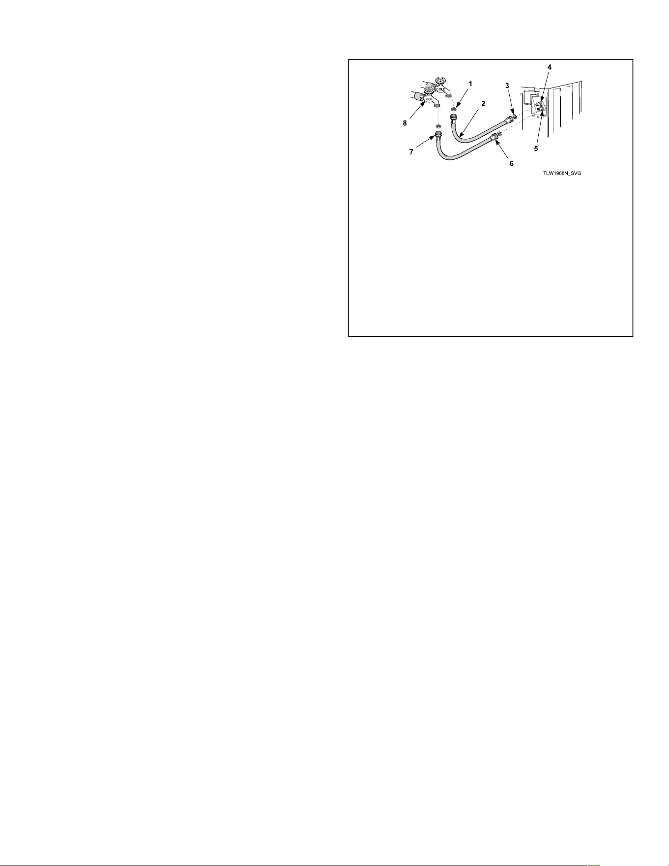
Connecting Hoses
1. Remove the two plain rubber washers and two filter screens
from the accessories bag.
2. Install them into each end of the fill hoses as shown in
Figure
4
. The screen must be facing outward.
3. Screw hose couplings with the filter screens onto the water
faucets until they are finger-tight. Use the red color-coded
hose for the hot water connection and the blue color-coded
hose for the cold water connection.
4. Then, using a pliers, screw approximately 1/4 turn.
5. Screw hose couplings from other end of hoses onto the water
mixing valve until they are finger-tight. Make sure the red
color-coded hose from the hot water faucet goes to the water
mixing valve marked “H” and the blue color-coded hose
from the cold faucet goes to the valve marked “C”. Refer to
Figure
Figure 4
.
6. Then, using a pliers, screw approximately 1/4 turn.
IMPORTANT: DO NOT cross thread or overtighten
couplings. This will cause them to leak.
7. Turn water on and check for leaks.
8. If leaks are found, turn off the water, unscrew hoses and rein-
stall them until there are no leaks.
IMPORTANT: Turn off water supply whenever
there will be an extended period of non-use.
1. Filter Screen (Screen must be facing outward)
2. Fill Hose
3. Rubber Washer (Plain)
4. Cold Water Connection
5. Hot Water Connection
6. Install this end of hose to valve connections at rear of wash-
er.
7. Install this end of hose to water supply faucet.
8. Faucet
Figure 4
IMPORTANT:
Hoses and other rubber parts deteriorate after ex-
tended use. Hoses may develop cracks, blisters or
material wear from the temperature and constant
high pressure they are subjected to.
All hoses should be checked on a monthly basis for
any visible signs of deterioration. Any hose show-
ing the signs of deterioration listed above should be
replaced immediately. All hoses should be replaced
every five years.
Connect Drain Hose to Drain
Receptacle
1. Remove the drain hose from its shipping position on the rear
of the washer by unhooking the hose from the retainer
clamp.
2. Install the drain hose into the drain receptacle (standpipe, wall
or laundry tub) following the instructions below.
NOTE: Drain receptacle must be capable of han-
dling a minimum of 32 mm [1-1/4 inch] outside di-
ameter drain hose.
Standpipe Installation
1. Check standpipe height. The recommended height for the
standpipe is 914 mm [36 inches] . Standpipes higher than
1220 mm [4 feet] will result in slower draining and may ex-
tend cycle times.
Installation
© Copyright, Alliance Laundry Systems LLC -
DO NOT COPY or TRANSMIT
7 Part No. 204104ENR5
NOTE: Machine will not drain if standpipe is high-
er than 2438 mm [8 feet] .
2. Place the drain hose into the standpipe.
IMPORTANT: To prevent siphoning, do not place
any ribbed portion of the drain hose into the
standpipe.
3. Remove the beaded strap from accessories bag and place
around standpipe and drain hose, approximately 300 mm [12
inches] down from the top of pipe. Refer to
Figure 5
.
a. Insert the end of the beaded strap into the larger hole
found on the end of the strap.
b. Tighten to desired fit.
c. Lock strap in place by pulling beaded strap into the ta-
pered smaller opening of the beaded strap end. A dis-
tinct snap noise should be heard once the strap is proper-
ly seated.
d. Pull on the strap once locked in place to ensure beaded
strap is properly installed. This will prevent the drain
hose from dislodging from drain receptacle during use.
TLW2341N_SVG
4
5
3
2
1
1. Ribbed Portion of Drain Hose
2. Beaded Strap
3. Standpipe - 51mm [2 in.] or 40 mm [1-1/2 in.] Diameter
4. 914 mm [36 in.] Recommended Height
5. 305 mm [12 in.]
Figure 5
Low Standpipe Installation
If standpipe is lower than 36 inches [914 mm] , you must in-
stall No. 562P3 Siphon Break Kit. This kit is available (as op-
tional equipment at extra cost) through an authorized dealer or
parts distributor. Installation instructions are supplied with the
kit.
TLW2283N_SVG
2
1
3
1. 562P3 Siphon Break Kit
2. Standpipe
3. Drain Hose
Figure 6
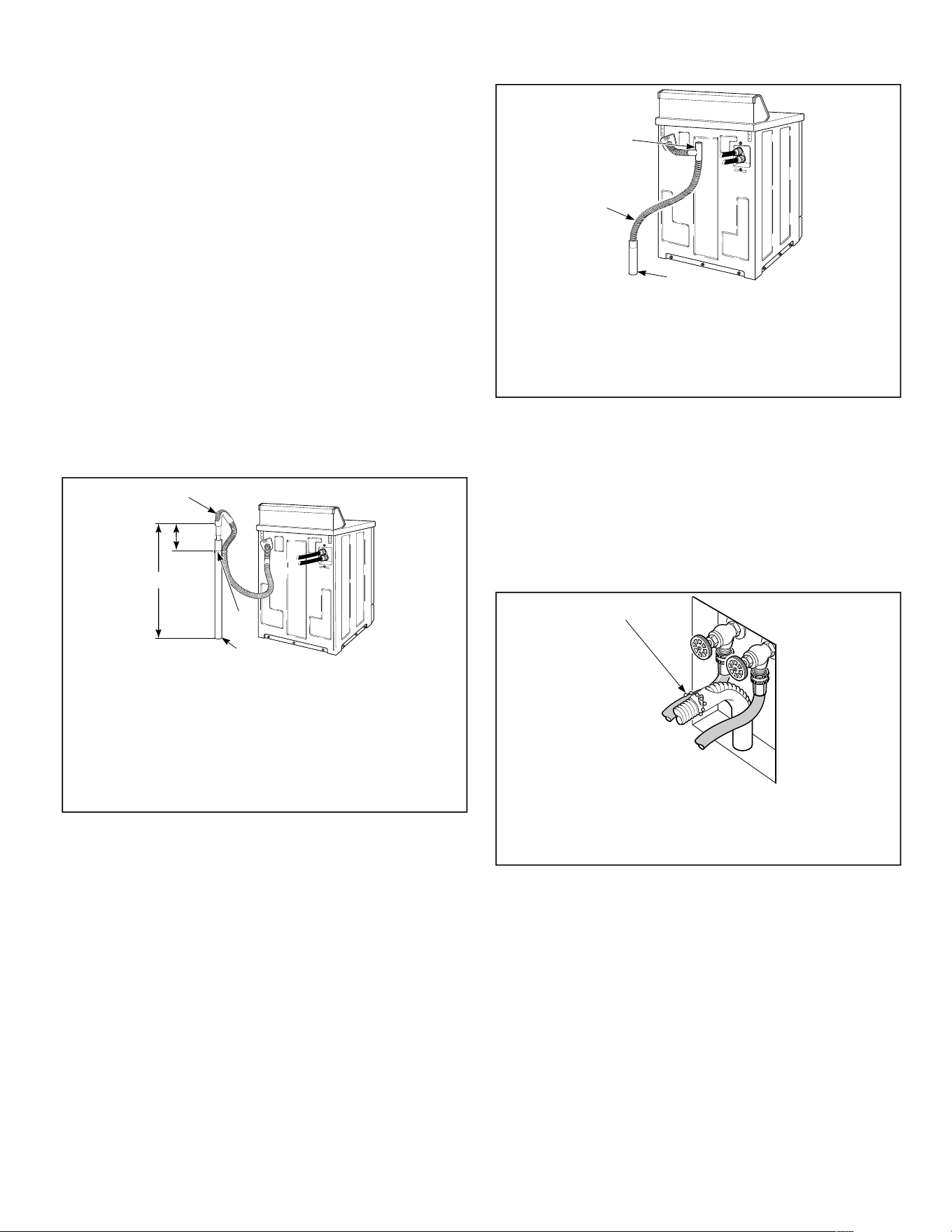
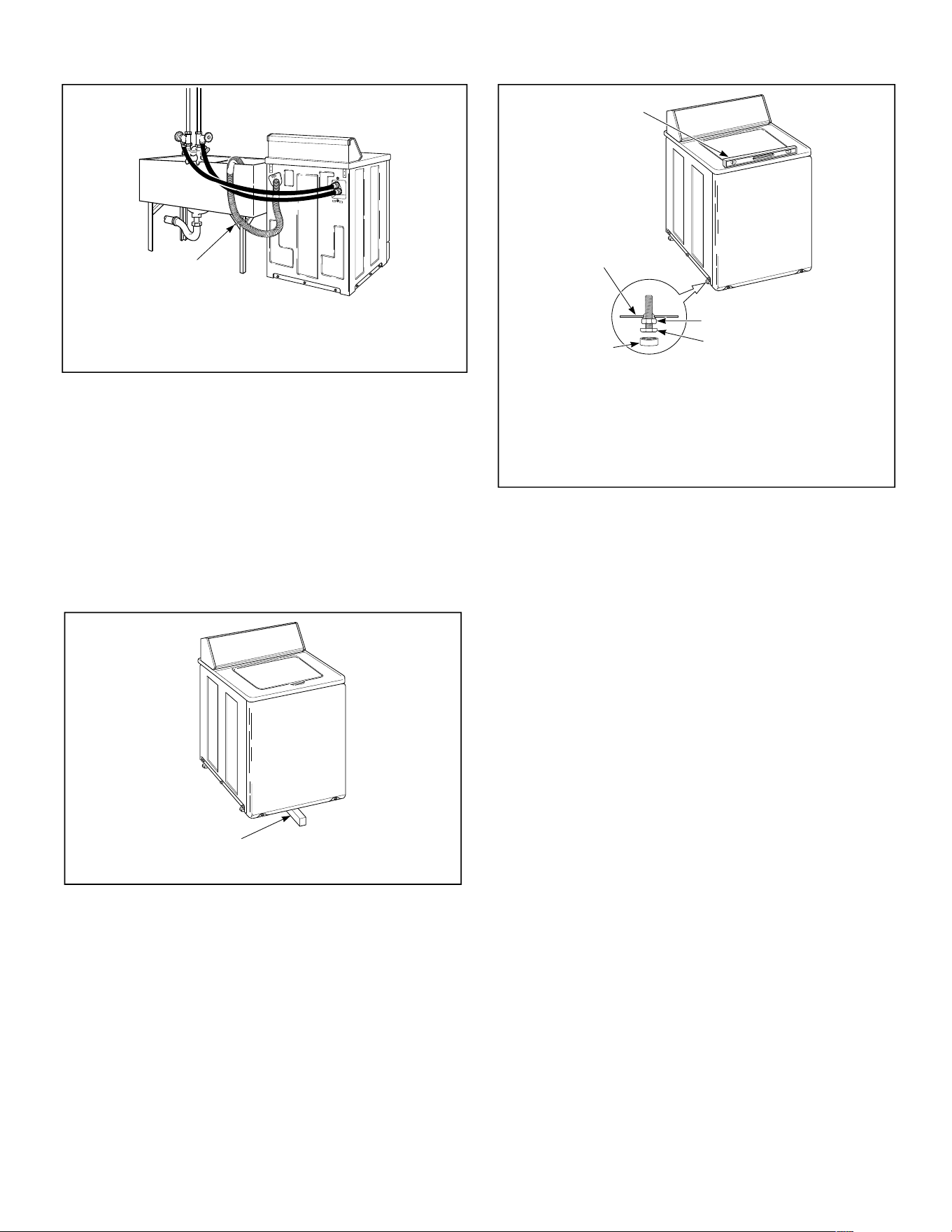
Wall Installation
Check wall drain height. The recommended height for the
drain is 36 inches [914 mm] .
For installations of this type, the drain hose MUST be secured
to one of the fill hoses using the beaded strap from accessories
bag. Refer to
Figure 7
.
TLW2342N_SVG
1
1. Beaded Strap (tape if necessary)
Figure 7
Laundry Tub Installation
For this type of installation, the drain hose MUST be secured
to the stationary tub to prevent hose from disloding during use.
Use the beaded strap (supplied in accessories bag) to secure
hose.
Installation
© Copyright, Alliance Laundry Systems LLC -
DO NOT COPY or TRANSMIT
8 Part No. 204104ENR5
TLW2284N_SVG
1
1. Beaded Strap (tape if necessary)
Figure 8
Position and Level the Washer
1. Position washer so it has sufficient clearance for installation
and servicing.
2. Place washer in position on a clean, dry, and reasonably firm
floor. Installing the washer on any type of carpeting is not
recommended.
3. For easier access to leveling legs, prop up washer with a
wooden block.
TLW2285N_SVG
1
1. Wood Block
Figure 9
4. Place rubber cups (from accessories bag) on all four leveling
legs.
TLW2286N_SVG
5
4
3
2
1
1. Level
2. Locknut
3. Leveling Leg
4. Rubber Cup
5. Washer Base
Figure 10
5. Place a level on the cabinet top and check if the washer is lev-
el from side to side and front to back.
6. If washer is not level, tilt washer back to access the front lev-
eling legs. Loosen the locknuts and adjust legs by screwing
into or out of washer base.
7. Once adjusted, tilt the washer forward on front legs and lower
back down into position to set the rear self-leveling legs.
8. Washer must not rock. When washer is level and does not
rock, tighten locknuts securely against bottom of washer
base. If these locknuts are not tight, washer will not remain
stationary during operation.
Improper installation or flexing of weak floor will cause ex-
cessive vibration.
Do not slide washer across floor once the leveling legs have
been extended, as legs and base could become damaged.
9. Verify that unit does not rock.
Plug In the Washer
Electrical Requirements
120 Volt, 60 Hertz with 3-Prong Earth/Ground Plug
NOTE: The wiring diagram is located in the control
hood.
Installation
© Copyright, Alliance Laundry Systems LLC -
DO NOT COPY or TRANSMIT
9 Part No. 204104ENR5
WARNING
To reduce the risk of fire, electric shock, serious
injury or death, all wiring and protective earth/
ground connections MUST conform with the latest
edition of the National Electrical Code, ANSI/NFPA
No. 70, and such local regulations as might apply. It
is the customer’s responsibility to have the wiring,
fuses and circuit breakers installed by a qualified
electrician to make sure adequate electrical power
is available to the washer.
W824
When plugging in the washer:
• DO NOT overload circuits.
• DO NOT use an extension cord.
• DO NOT use an adapter.
• DO NOT operate other appliances on the same circuit. Use
separately fused 15 Amp circuits.
The washer is designed to be operated on a separate branch,
polarized, three-wire, effective earth/ground, 120 Volt, 60
Hertz, AC (alternating current), circuit protected by a 15 am-
pere fuse, equivalent fusetron or circuit breaker.
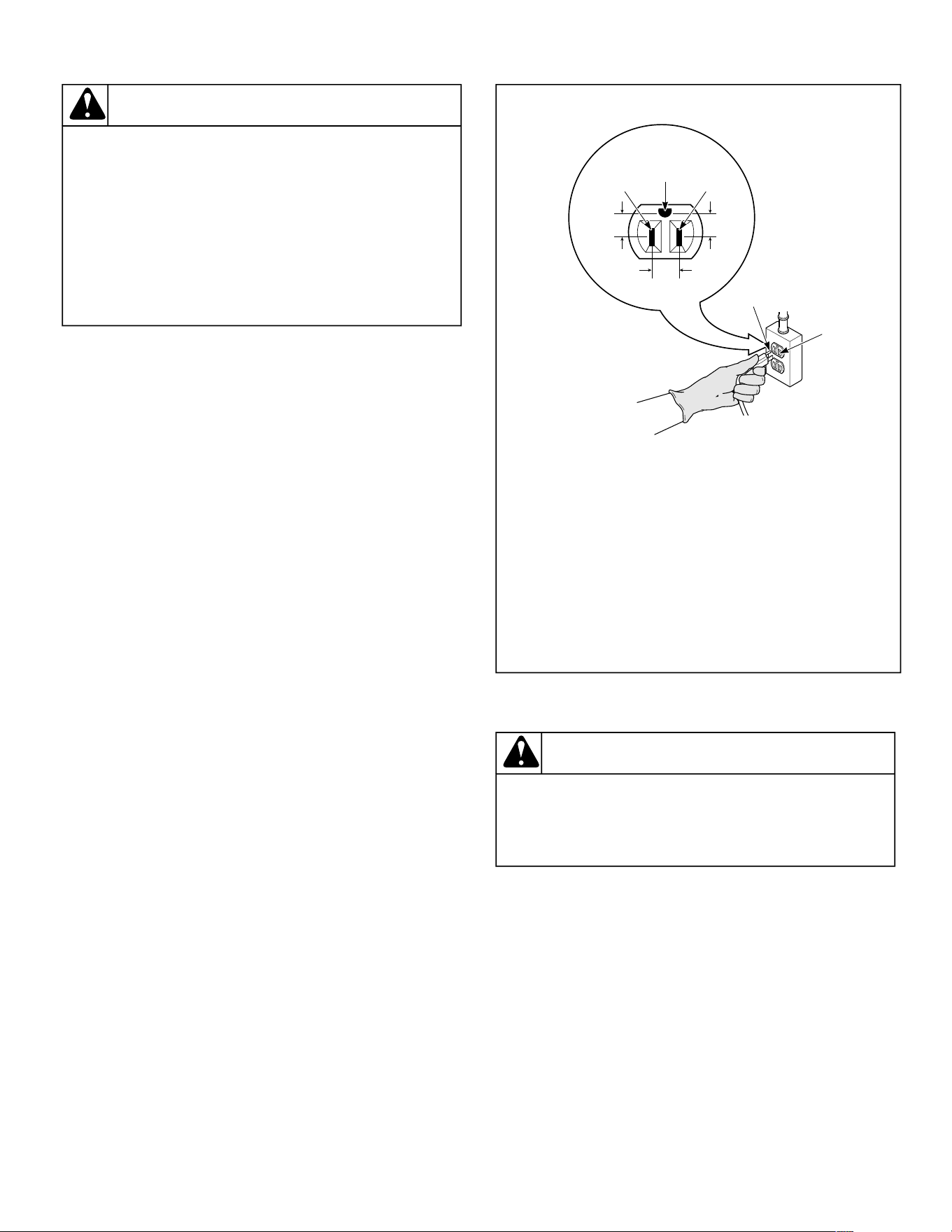
The three-prong earth/ground plug on the power cord should
be plugged directly into a polarized three-slot effective earth/
ground receptacle rated 110/120 Volts AC (alternating current)
15 Amps. Refer to
Figure 11
to determine correct polarity of
the wall receptacle.
Standard 120 Volt, 60 Hertz 3-Wire Effective Earth/
Ground Circuit
TLW2287N_SVG
6
8
7
2
1 3
5
4
1. L1
2. Earth/Ground
3. Neutral Side
4. Round Earth/Ground Prong
5. Neutral
6. 0 V.A.C.
7. 120 ± 12 V.A.C.
8. 120 ± 12 V.A.C.
Figure 11
WARNING
To reduce the risk of an electric shock or fire, DO
NOT use an extension cord or an adapter to
connect the washer to the electric power source.
W082
Earth/Ground Instructions
This appliance must be properly connected to protective earth/
ground. In the event of malfunction or breakdown, the earth/
ground will reduce the risk of electric shock by providing a
path of least resistance for electric current.
The appliance is equipped with a cord having an equipment
earth/ground conductor and a three-prong earth/ground plug.
The plug must be plugged into an appropriate outlet that is
properly installed and connected to a protective earth/ground
in accordance with all local codes and ordinances.
Installation
© Copyright, Alliance Laundry Systems LLC -
DO NOT COPY or TRANSMIT
10 Part No. 204104ENR5

WARNING
Improper connection of the equipment earth/ground
conductor can result in a risk of electric shock.
Check with a qualified electrician or service person
if you are in doubt as to whether the unit is properly
connected to a protective earth/ground.
W893
• DO NOT modify the plug provided with the unit – if it will
not fit the outlet, have a proper outlet installed by a qualified
electrician.
• If the laundry room’s electrical supply does not meet the
above specifications and/or if you are not sure the laundry
room has an effective earth/ground, have a qualified electri-
cian or your local electrical utility company check it and cor-
rect any problems.
WARNING
This unit is equipped with a three-prong (earth/
ground) plug for your protection against shock
hazard and should be plugged directly into a
protective earth/ ground three-prong receptacle. Do
not cut or remove the earth/ground prong from this
plug.
W823
Check Lid Lock
To check lid lock, start a cycle. Once the red Lid Locked status
light is lit and stops flashing, make sure the lid has locked.
Check Installation
1. Refer to Installer Checklist on the back cover of this manual
and make sure that washer is installed correctly.
2. Run washer through one complete cycle to make sure it is
operating properly.
Installation
© Copyright, Alliance Laundry Systems LLC -
DO NOT COPY or TRANSMIT
11 Part No. 204104ENR5
continues...
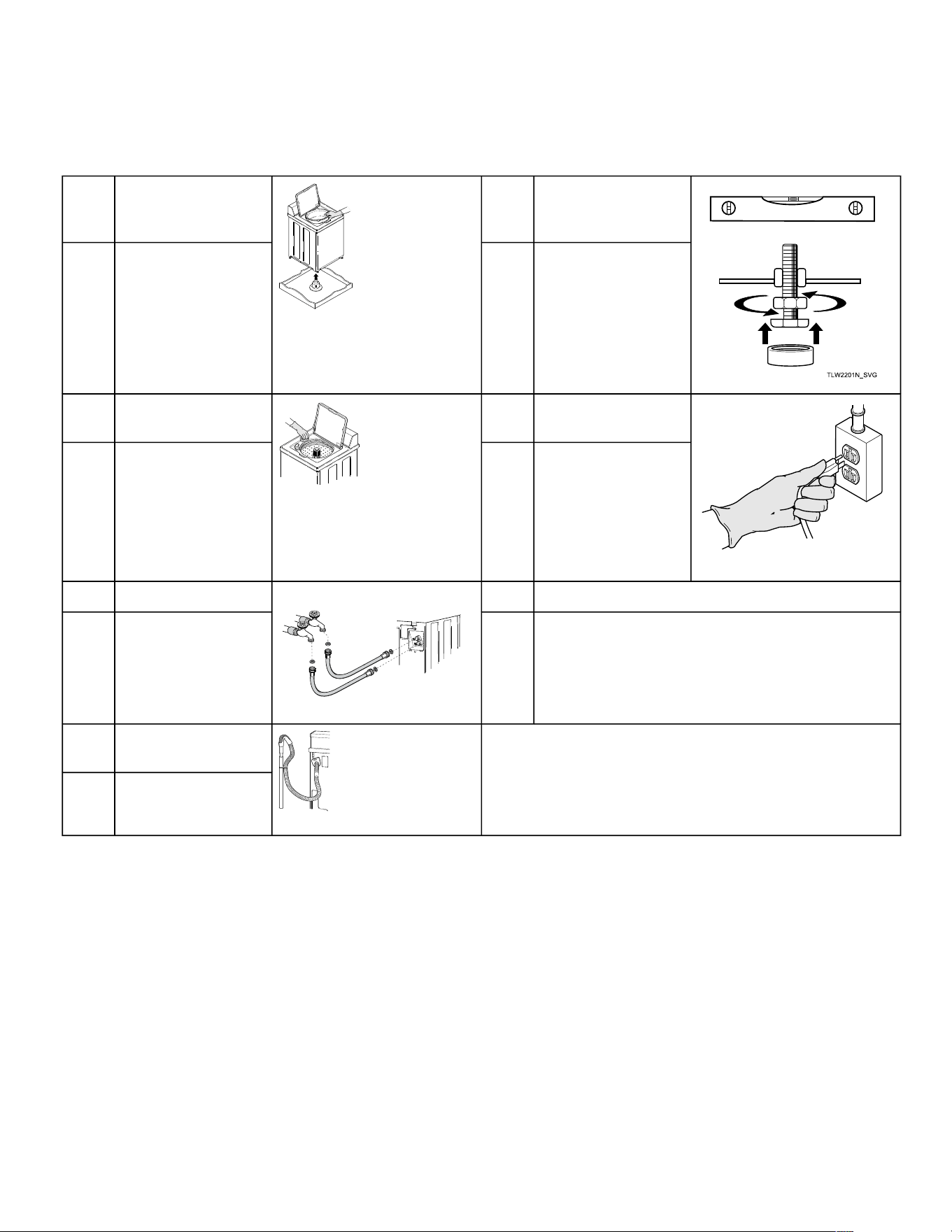
Installer Checklist
Fast Track for Installing the Washer
1 Remove the Shipping
Brace and Shipping
Plug.
TLW2280N_SVG1
5 Position and Level the
Washer.
CHECK CHECK
2 Wipe Out Inside of
Washtub.
TLW2281N_SVG1
6 Plug In the Washer.
TLW2289N_SVG
CHECK CHECK
3 Connect Fill Hoses.
TLW1988N_SVG
HOT
COLD
7 Check Lid Lock.
CHECK CHECK
4 Connect Drain Hose to
Drain Receptacle.
TLW2288N_SVG
CHECK
Refer to the manual for more detailed information.
Installer Checklist
© Copyright, Alliance Laundry Systems LLC -
DO NOT COPY or TRANSMIT
12 Part No. 204104ENR5