User Guide
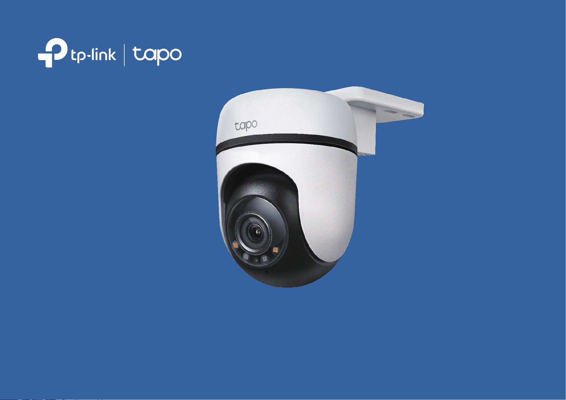
Outdoor Pan/Tilt Security Wi-Fi Camera
©2024 TP-Link 1910013849 REV2.1.0

Contents
About This Guide ···········································································1
Introduction ······················································································ 2
Appearance ······················································································3
Set Up Your Camera ·····································································5
Set Up Using Amazon Frustration-Free Setup ··············6
Install a microSD Card ······························································10
Mount Your Camera··································································· 11
Install Waterproof Items ·························································· 14
Authentication ··············································································15
1
About This Guide
This guide provides a brief introduction to the Outdoor Pan/Tilt Security Wi-Fi Camera and the Tapo app, as well as regulatory information.
Please note that features available in Tapo may vary by model and software version. Tapo availability may also vary by region. All images, steps, and
descriptions in this guide are only examples and may not reect your actual Tapo Camera experience.
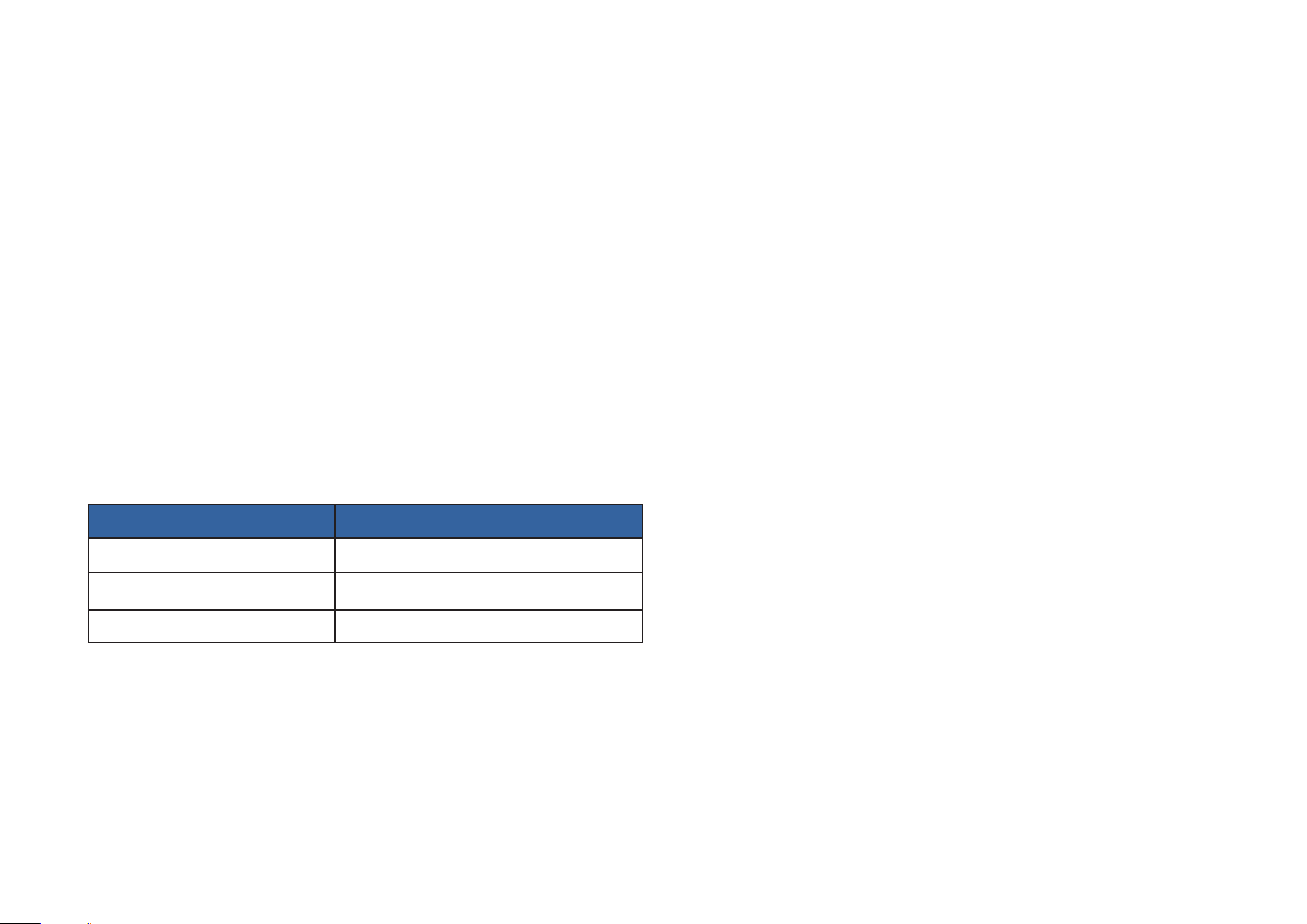
Conventions
In this guide, the following convention is used:
Convention Description
Blue
Key information appears in blue, including management page text such as menus, items, buttons and so on.
Underline
Hyperlinks are in blue and underlined. You can click to redirect to a website.
Note:
Ignoring this type of note might result in a malfunction or damage to the device.
More Info
• Specications can be found on the product page at https://www.tapo.com.
• Our Technical Support and troubleshooting information can be found at https://www.tapo.com/support/.
• The setup video can be found at https://www.tp-link.com/support/setup-video/#cloud-cameras.

2
Introduction
Outdoor Pan/Tilt Security Wi-Fi Camera is a full-featured weatherproof security camera that you can access from anywhere. Receive instant
notications and check feeds when the motion is detected. Moreover, the automatic siren system will trigger light and sound to frighten away unwanted
visitors after the camera detects motion.
Day or night, rain or shine, the Tapo camera protects what you love most.
• 2K Live View – With the resolution of 2304 × 1296 px , the Tapo camera enhances your security by capturing vivid details.
• 360° Motion Tracking – The Tapo camera ensures comprehensive coverage with 360° horizontal and 130° vertical views, capable of tracking a
person within its eld of view.
• Patrol Mode – Keep the camera cruise between two customized points for dynamic monitoring.
• Person Detection – Noties you when a person is detected.
• Local* and Cloud** Storage – Save recorded videos to an installed microSD card (up to 512 GB)*, or use Tapo Care** cloud storage service.
*microSD card must be purchased separately.
**Subscribe for cloud storage at https://www.tapo.com/tapocare/
• IP65 Weatherproof – Oers excellent waterproof and dustproof performance for outdoor scenarios.
• Customizable Sound Alarm – Record your own audio as an alarm to extend your usage.
• Color Night Vision – Enhances your security by revealing vivid colors with built-in spotlights.
• Two-Way Audio – Communicate remotely with a delivery person in real time.
• Multiple Installation Options – Use the mounting screws, template and loops* to install on any wall, ceiling or pole for the perfect view.
*Mounting loops purchased separately.
• Activity Zones – Noties you when activity is detected in specic zones.
3
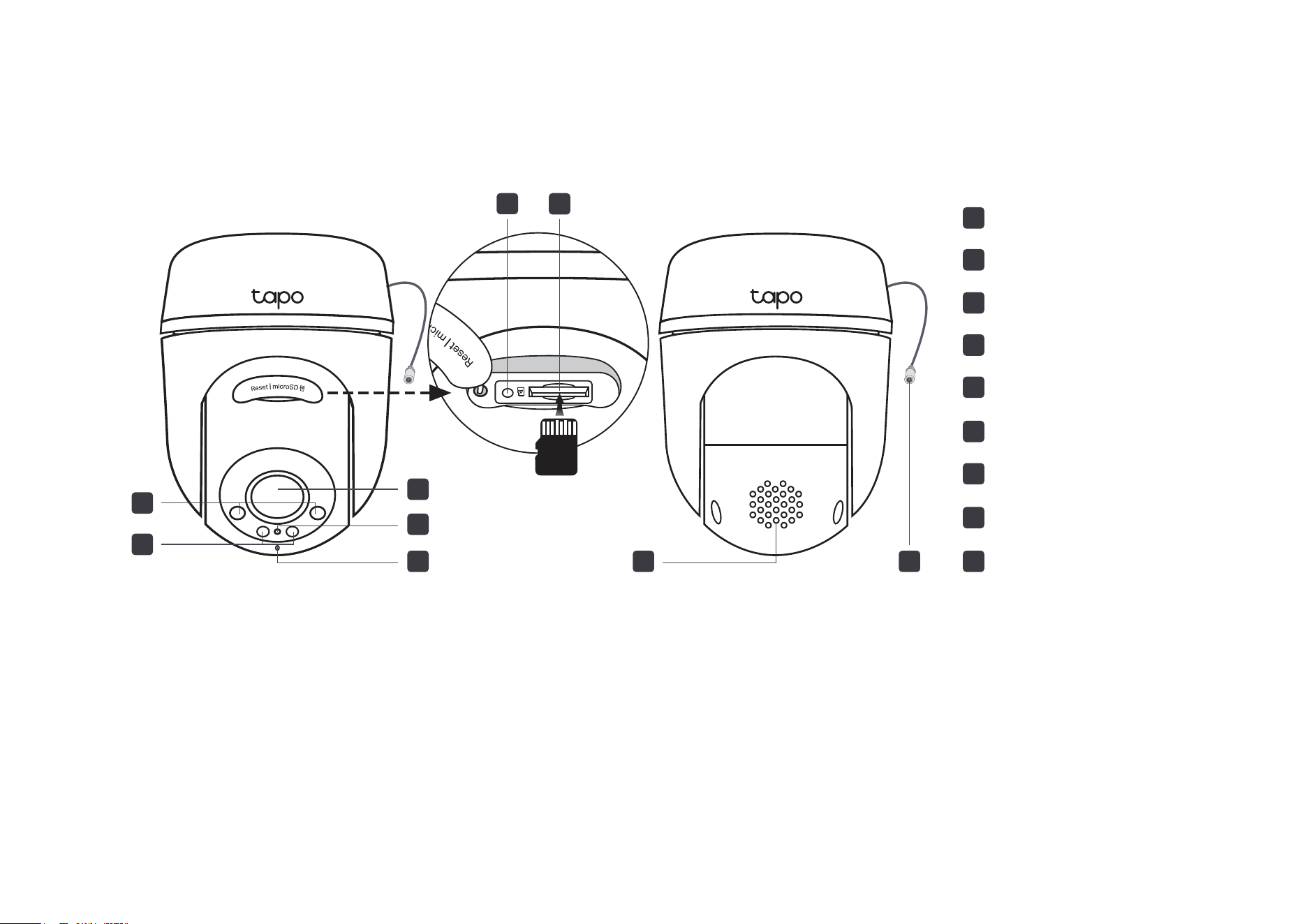
Appearance
microSD
2
3
Lens
4
System LED
5
Microphone
IR LEDs
1
White Light LEDs
6
Reset
8
Speaker
9
DC Power Connector
7
microSD Card Slot
8
7
6
2
1
3
4
5
9
Reset Button
Open the silicone cover. While the camera is powered on, use a pin to press and hold the RESET button to reset the camera.
• Press and hold for 5s: Reset Wi-Fi settings only
• Press and hold for 10s: Reset to factory settings
microSD Card Slot
Open the silicone cover and insert a microSD card*. Initialize it on the Tapo app for local recording.
*microSD card not included.
DC Power Connector
Used to connect to the provided DC power adapter
4
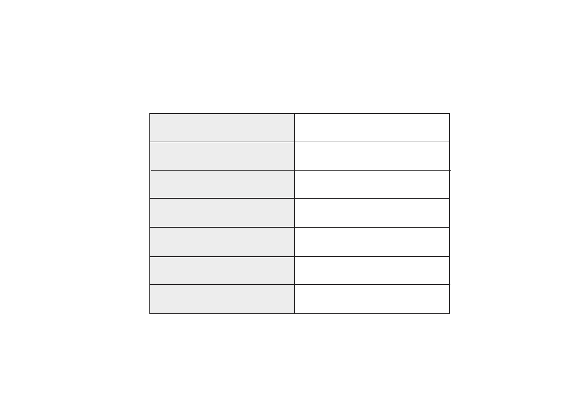
System LED Indication
Blinking red and green
Blinking red slowly
Solid amber
Blinking red quickly
Solid red
Solid green
Blinking green quickly
Starting up
Connected to the cloud
Ready for setup
Connecting to Wi-Fi
Connected to Wi-Fi
Camera resetting
Camera updating
5
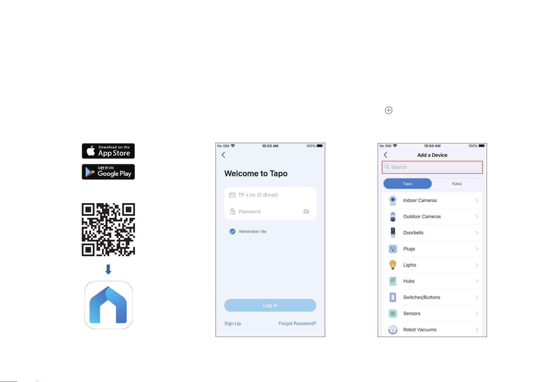
Set Up Your Camera
Follow the steps below to get started with your new camera.
Step 1. Download Tapo App
Get the Tapo app from the App Store or
Google Play, or by scanning the QR code
below.
Step 2. Log In
Open the app, and log in with your TP-Link ID.
If you don't have an account, create one rst.
Step 3. Add Your Camera
Tap the button > Add Device in the app and
search for your model. Follow app instructions
to complete the setup.
OR
6
Set Up Using Amazon Frustration-Free Setup
What is Amazon Frustration-Free Setup?
Amazon Frustration-Free Setup can help connect and set up Tapo smart devices in fewer steps, without having to remember and re-enter your Wi-Fi
password on each device.
To use this feature, conrm the following:
● The new Tapo device supports Amazon FFS.
● The new Tapo device is purchased from Amazon.
● You have an Amazon FFS enabled Alexa device or router.
● You have saved your Wi-Fi information to Amazon by using Alexa echo.
● Your Tapo device and router are on the same network as your Alexa echo.
LED Indications during Amazon Frustration-Free Setup
LED Status
Blinking red and green Ready for setup
Blinking amber FFS setup in progress
Solid green Working properly
If the LED does not turn solid green after a long time, you can try to add the Tapo device manually. (Press the Reset button on your Tapo device once.
Then open the Tapo app, tap the + button on the page, select your device model, and follow the app instructions. )
7
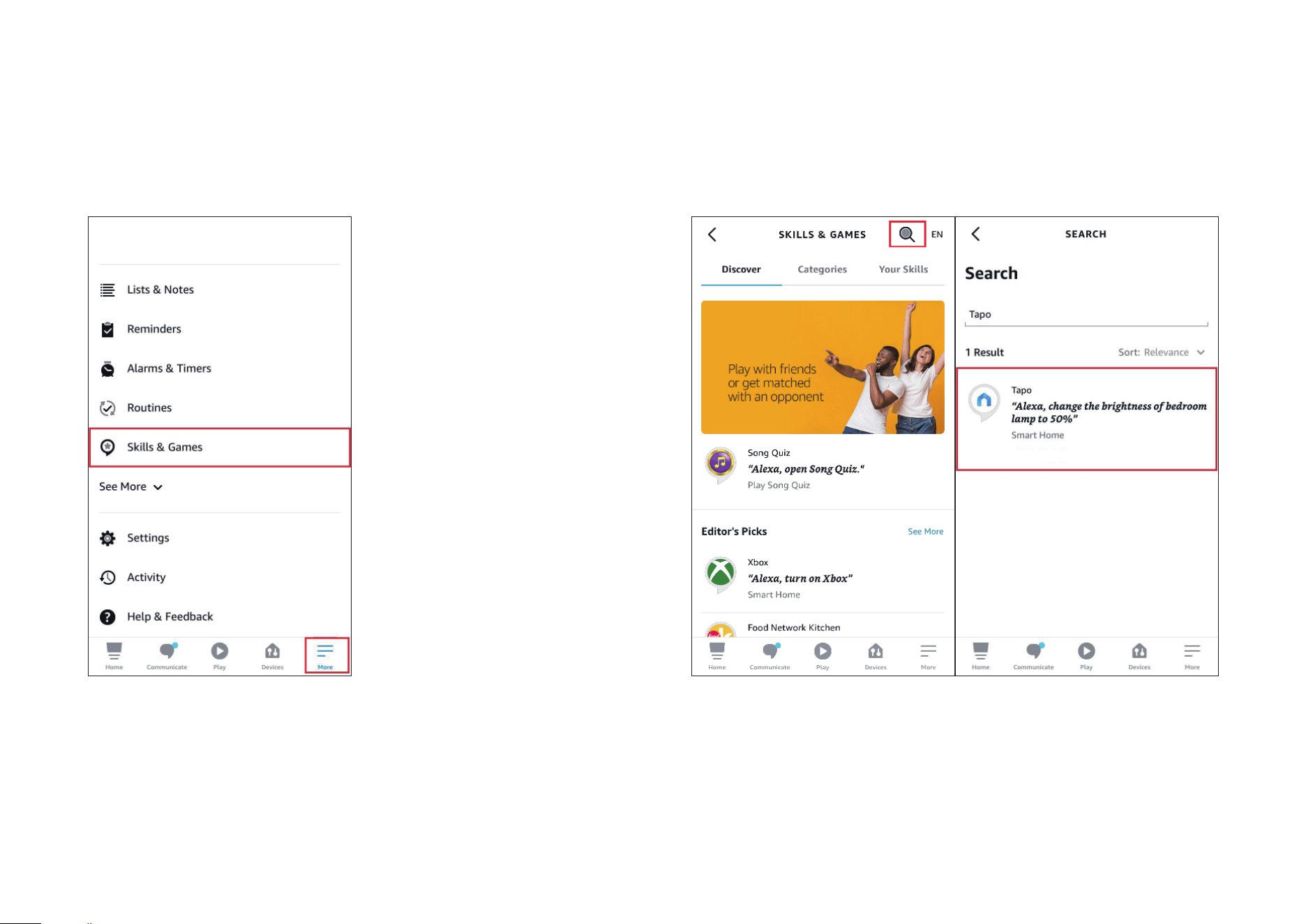
1. Open the Amazon Alexa app. Then tap More and select Skills &
Games.
How to use Amazon Frustration-Free Setup with Tapo devices
2. Enter Tapo in the search bar and choose Tapo.
8
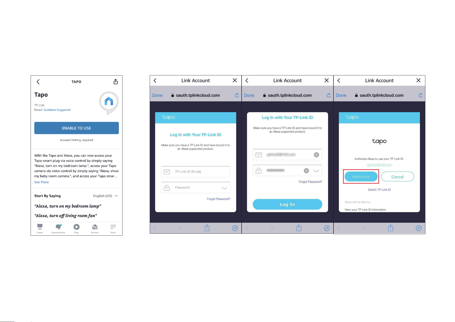
3. Tap the ENABLE TO USE button.
4. Log in with your TP-Link ID that has bound to your Tapo device, and tap Authorize. After authorized
successfully, the message Tapo has been successfully linked will come up.

9
5. Plug in your Tapo device and the setup will complete automatically in two minutes.
For setting up more Tapo devices, just plug in and enjoy!
Done!
If this device displays on the Home page in the Tapo app, it indicates this device has been successfully associated with your Amazon account and
joined your Wi-Fi network automatically.
If this device does not display on the Home page in the Tapo app, try setting it up manually. (Tap the + button on the page, select your device model,
and then follow the app instructions.)
10
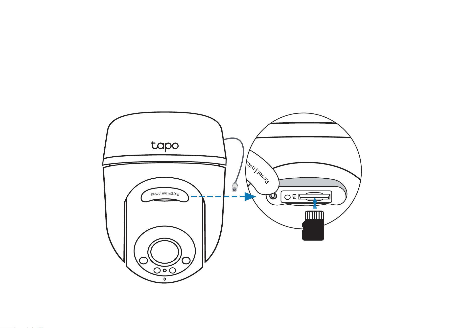
Install a microSD Card
Follow the steps below to install the microSD card for local recording.
You can go to Camera Settings > microSD Card in the Tapo app to check the card status or format your card.
1. Manually rotate the camera downwards. Open the silicone cover to
nd the microSD card slot.
2. Identify the direction of the microSD card and carefully insert the card
into the slot. Push in the card until you hear a clicking sound.
microSD
11
Mount Your Camera
When you nish adding your camera in the Tapo app, you can mount it on a wall or ceiling with the provided mounting template and screws. You can
also mount it on the pole with mounting loops. Follow the steps below to mount your new camera.
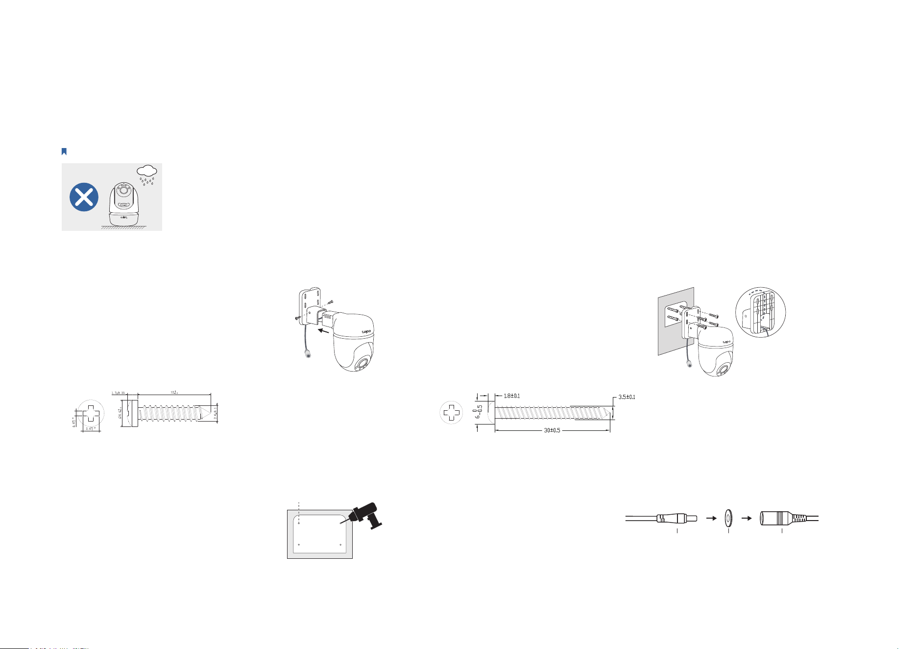
Note: The camera is not waterproof when set on a table or shelf. Mount the camera via Option 1-3 when installing outdoors.
Option 1: Wall Mount
Route the camera power cord
through the opening of the
bracket. Use two bracket screws
to ax the bracket and the
camera.
1. Ax the Camera and Bracket
Insert four mounting anchors into
the holes, then use the mounting
screws to ax the camera and
bracket over the anchors.
3. Mount the Camera
4. Power Up the Camera
Stick the mounting template to
the desired mounting place. Drill
four screw holes according to
the template.
2. Drill Holes
Φ=6 mm (15/64 in.)
Connect the camera to a power
outlet using the provided power
adapter. Install the waterproof
seal for the power connectors.
Male Power Connector Waterproof Seal
Female Power Connector
12
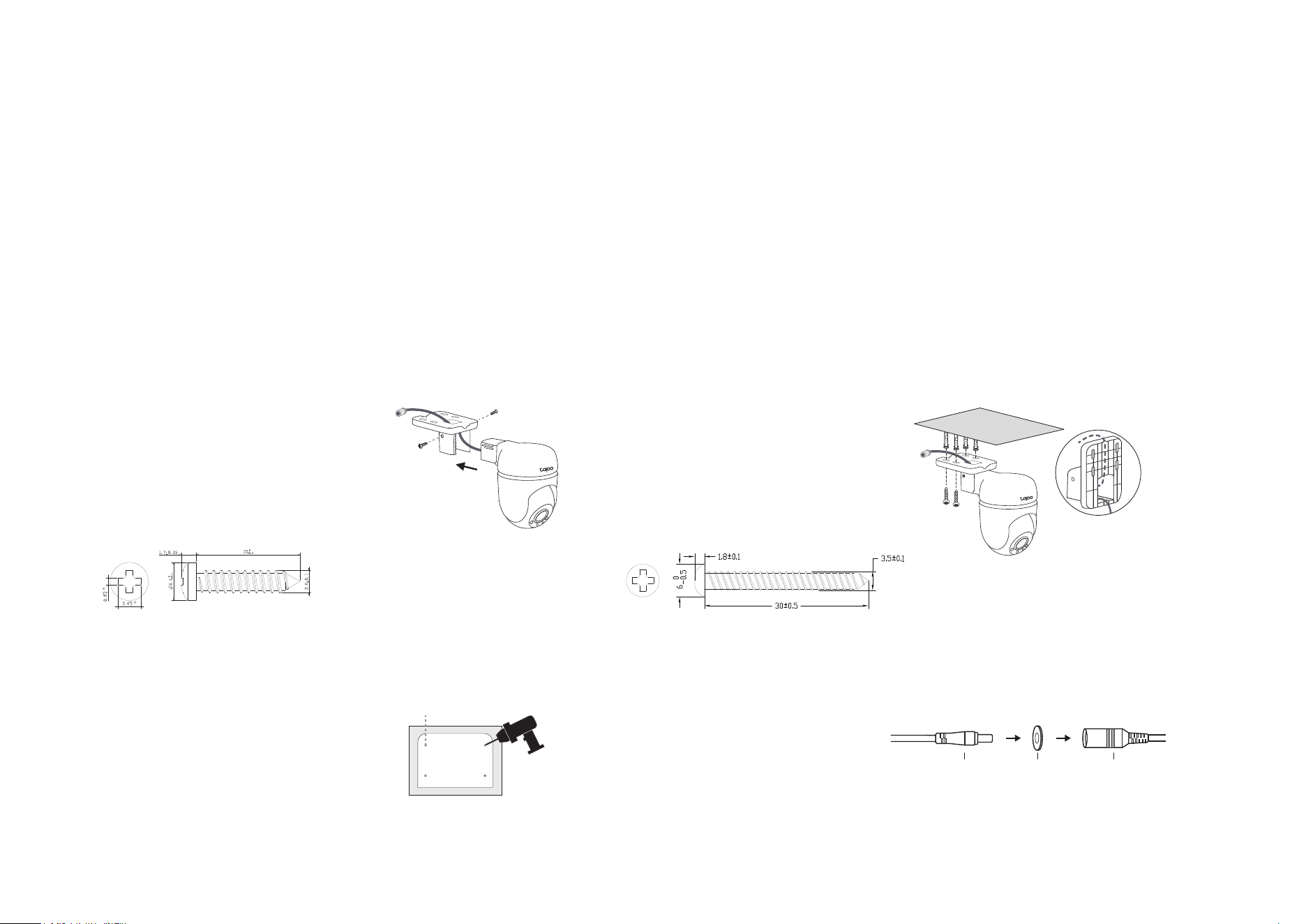
Option 2: Overhang Mount
Route the camera power cord
through the opening of the
bracket. Use two bracket screws
to ax the bracket and the
camera.
1. Ax the Camera and Bracket
Insert four mounting anchors into
the holes, then use the mounting
screws to ax the camera and
bracket over the anchors.
3. Mount the Camera
4. Power Up the Camera
Stick the mounting template to
the desired mounting place. Drill
four screw holes according to
the template.
2. Drill Holes
Φ=6 mm (15/64 in.)
Connect the camera to a power
outlet using the provided power
adapter. Install the waterproof
seal for the power connectors.
Male Power Connector Waterproof Seal
Female Power Connector
13
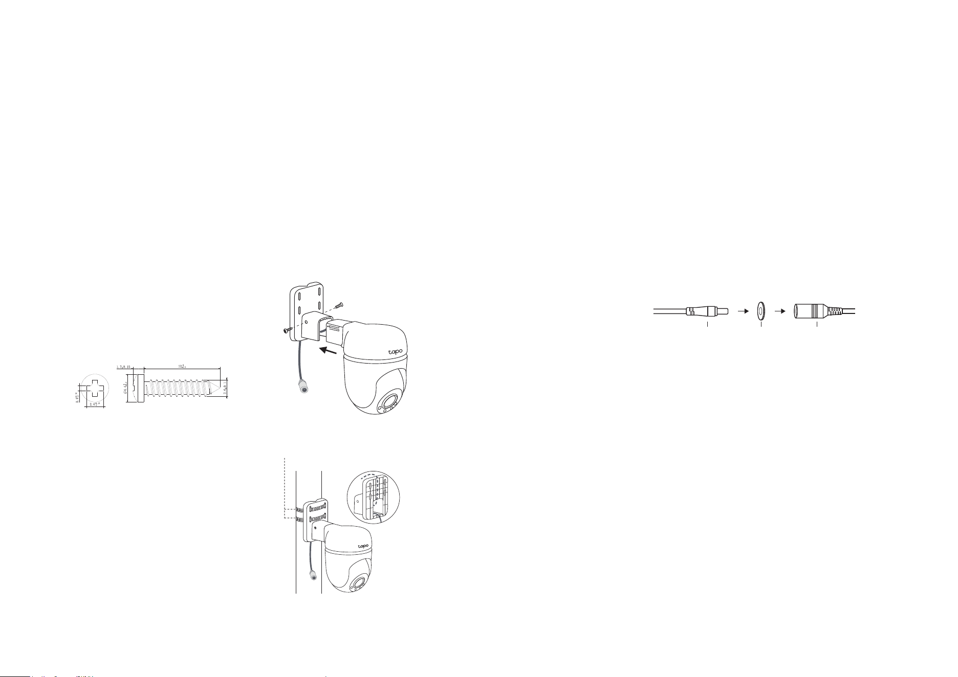
Option 3: Pole Mount
3. Power Up the Camera
Connect the camera to a power
outlet using the provided power
adapter. Install the waterproof
seal for the power connectors.
Male Power Connector Waterproof Seal
Female Power Connector
Mount the camera on the pole
using two pole-mounting loops*
(loop width ≤ 12mm).
2. Mount the Camera
*Pole-mounting loops are not included.
Pole-mounting loops
Route the camera power cord
through the opening of the
bracket. Use two bracket screws to
ax the bracket and the camera.
1. Ax the Camera and Bracket
14
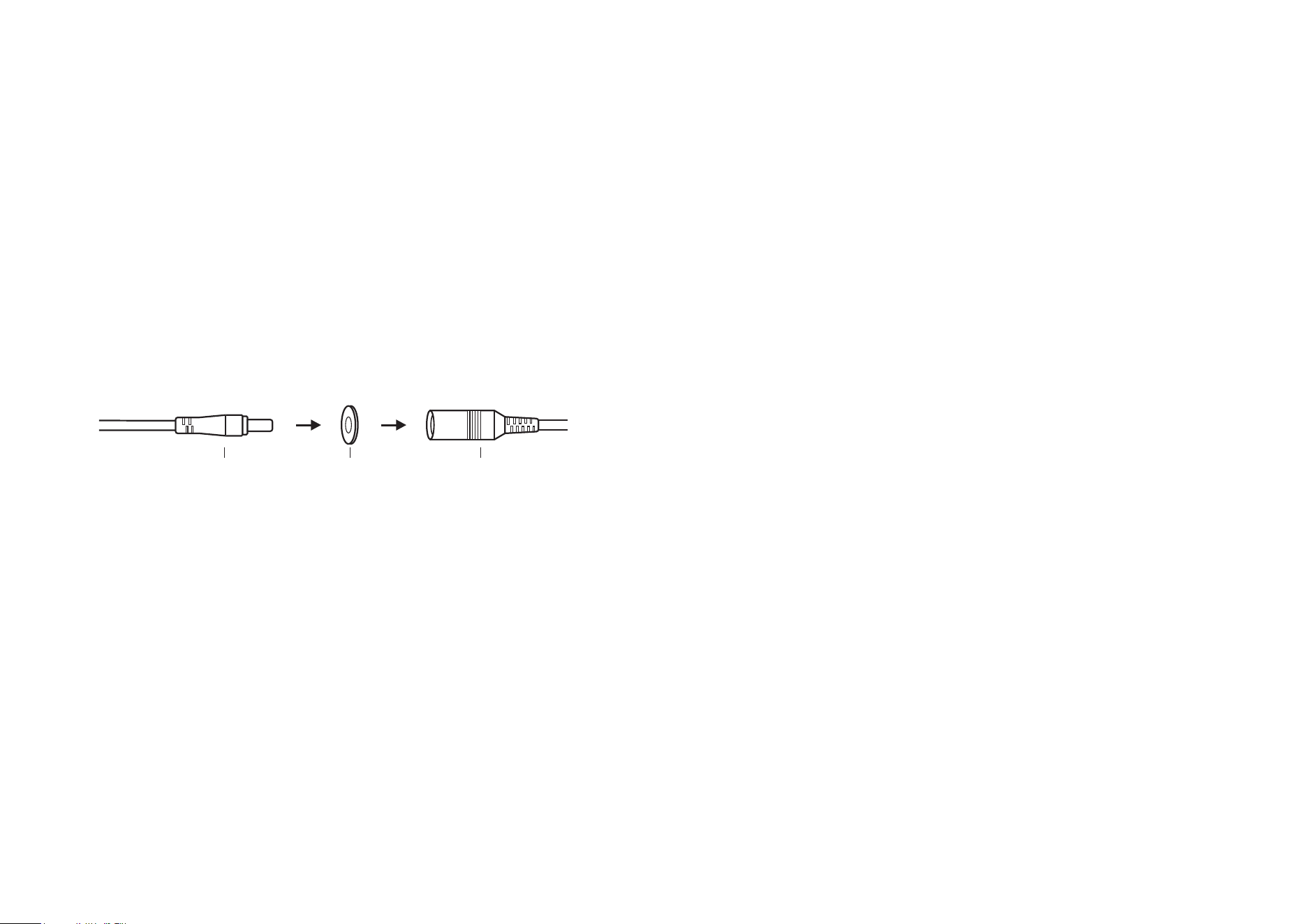
Install Waterproof Items
When the camera is installed outdoors, please install waterproof items to waterproof your camera. Make sure each part is securely attached and the
water-proong rings are ush to keep out water.
Follow the steps below to install waterproof items.
Install Waterproof Seal for Power Connectors
Connect the camera to a power outlet using the provided power adapter. Install the waterproof seal for the power connectors when the camera is
installed outdoors.
Male Power Connector Waterproof Seal Female Power Connector
15
Authentication
FCC compliance information statement
Product Name: Outdoor Pan/Tilt Security Wi-Fi Camera
Model Number: Tapo C510W/Tapo C51A
Component Name Model
I.T.E. Power Supply T090085-2B1
Responsible Party:
TP-Link Systems Inc.
Address: 10 Mauchly, Irvine, CA 92618
Website: http://www.tp-link.com/us/
Tel: +1 626 333 0234
Fax: +1 909 527 6804
E-mail: [email protected]om
This equipment has been tested and found to comply with the limits for a Class B digital device, pursuant to part 15 of the FCC Rules. These limits are
designed to provide reasonable protection against harmful interference in a residential installation. This equipment generates, uses and can radiate
radio frequency energy and, if not installed and used in accordance with the instructions, may cause harmful interference to radio communications.
However, there is no guarantee that interference will not occur in a particular installation. If this equipment does cause harmful interference to radio
or television reception, which can be determined by turning the equipment off and on, the user is encouraged to try to correct the interference by
one or more of the following measures:
• Reorient or relocate the receiving antenna.
• Increase the separation between the equipment and receiver.
• Connect the equipment into an outlet on a circuit different from that to which the receiver is connected.
• Consult the dealer or an experienced radio/ TV technician for help.
This device complies with part 15 of the FCC Rules. Operation is subject to the following two conditions:

16
1. This device may not cause harmful interference.
2. This device must accept any interference received, including interference that may cause undesired operation.
Any changes or modifications not expressly approved by the party responsible for compliance could void the user’s authority to operate the
equipment.
Note: The manufacturer is not responsible for any radio or TV interference caused by unauthorized modifications to this equipment. Such modifications
could void the user’s authority to operate the equipment.
FCC RF Radiation Exposure Statement
This equipment complies with FCC RF radiation exposure limits set forth for an uncontrolled environment. This device and its antenna must not be
co-located or operating in conjunction with any other antenna or transmitter.
“To comply with FCC RF exposure compliance requirements, this grant is applicable to only Mobile Configurations. The antennas used for this
transmitter must be installed to provide a separation distance of at least 20 cm from all persons and must not be co-located or operating in conjunction
with any other antenna or transmitter.”
We, TP-Link Systems Inc., has determined that the equipment shown as above has been shown to comply with the applicable technical standards,
FCC part 15. There is no unauthorized change is made in the equipment and the equipment is properly maintained and operated.
Issue Date: 2024-08-27
FCC compliance information statement
Product Name: I.T.E. Power Supply
Model Number: T090085-2B1
Responsible Party:
TP-Link Systems Inc.
Address: 10 Mauchly, Irvine, CA 92618
Website: http://www.tp-link.com/us/
Tel: +1 626 333 0234
Fax: +1 909 527 6804
E-mail: [email protected]om
This equipment has been tested and found to comply with the limits for a Class B digital device, pursuant to part 15 of the FCC Rules. These limits are

17
designed to provide reasonable protection against harmful interference in a residential installation. This equipment generates, uses and can radiate
radio frequency energy and, if not installed and used in accordance with the instructions, may cause harmful interference to radio communications.
However, there is no guarantee that interference will not occur in a particular installation. If this equipment does cause harmful interference to radio
or television reception, which can be determined by turning the equipment off and on, the user is encouraged to try to correct the interference by
one or more of the following measures:
• Reorient or relocate the receiving antenna.
• Increase the separation between the equipment and receiver.
• Connect the equipment into an outlet on a circuit different from that to which the receiver is connected.
• Consult the dealer or an experienced radio/ TV technician for help.
This device complies with part 15 of the FCC Rules. Operation is subject to the following two conditions:
1. This device may not cause harmful interference.
2. This device must accept any interference received, including interference that may cause undesired operation.
Any changes or modifications not expressly approved by the party responsible for compliance could void the user’s authority to operate the
equipment.
We, TP-Link Systems Inc., has determined that the equipment shown as above has been shown to comply with the applicable technical standards,
FCC part 15. There is no unauthorized change is made in the equipment and the equipment is properly maintained and operated.
Issue Date: 2024-08-27
18
CE Mark Warning
This is a class B product. In a domestic environment, this product may cause radio interference, in which case the user may be required to take
adequate measures.
OPERATING FREQUENCY (the maximum transmitted power)
2412MHz—2472MHz (20dBm)
EU Declaration of Conformity
TP-Link hereby declares that the device is in compliance with the essential requirements and other relevant provisions of directives 2014/53/EU,
2009/125/EC, 2011/65/EU and (EU)2015/863.
The original EU Declaration of Conformity may be found at https://www.tapo.com/en/support/ce/.
RF Exposure Information
This device meets the EU requirements (2014/53/EU Article 3.1a) on the limitation of exposure of the general public to electromagnetic fields by way
of health protection.
The device complies with RF specifications when the device used at 20 cm from your body.
UKCA Mark
UK Declaration of Conformity
TP-Link hereby declares that the device is in compliance with the essential requirements and other relevant provisions of the Radio Equipment
Regulations 2017.
The original UK Declaration of Conformity may be found at https://www.tapo.com/support/ukca/.
19
Canadian Compliance Statement
This device contains licence-exempt transmitter(s)/receiver(s) that comply with Innovation, Science and Economic Development Canada’s licence-
exempt RSS(s). Operation is subject to the following two conditions:
1. This device may not cause interference.
2. This device must accept any interference, including interference that may cause undesired operation of the device.
L’émetteur/récepteur exempt de licence contenu dans le présent appareil est conforme aux CNR d’Innovation, Sciences et Développement
économique Canada applicables aux appareils radio exempts de licence. L’exploitation est autorisée aux deux conditions suivantes :
1. l’appareil ne doit pas produire de brouillage;
2. l’utilisateur de l’appareil doit accepter tout brouillage radioélectrique subi, meme si le brouillage est susceptible d’en compromettre le fonctionnement
Radiation Exposure Statement:
This equipment complies with IC radiation exposure limits set forth for an uncontrolled environment. This equipment should be installed and operated
with minimum distance 20cm between the radiator & your body.
Déclaration d’exposition aux radiations:
Cet équipement est conforme aux limites d’exposition aux rayonnements IC établies pour un environnement non contrôlé. Cet équipement doit être
installé et utilisé avec un minimum de 20 cm de distance entre la source de rayonnement et votre corps.
Industry Canada Statement
CAN ICES-3 (B)/NMB-3(B)
À DÉPOSER
EN MAGASIN
À DÉPOSER
EN DÉCHÈTERIE
OU
FR
Cet appareil
et ses accessoires
se recyclent
Korea Warning Statements:
당해 무선설비는 운용중 전파혼신 가능성이 있음.
20
NCC Notice & BSMI Notice
注意!
取得審驗證明之低功率射頻器材,非經核准,公司、商號或使用者均不得擅自變更頻率、加大功率或變更原設計之特性及功能。
低功率射頻器材之使用不得影響飛航安全及干擾合法通信;經發現有干擾現象時,應立即停用,並改善至無干擾時方得繼續使用。
前述合法通信,指依電信管理法規定作業之無線電通信。
低功率射頻器材須忍受合法通信或工業、科學及醫療用電波輻射性電機設備之干擾。
為避免本器材影像畫面遭偷窺或擷取,本器材使用者應先修改預設密碼,並定期更新密碼。
安全諮詢及注意事項
• 請使用原裝電源供應器或只能按照本產品注明的電源類型使用本產品。
• 清潔本產品之前請先拔掉電源線。請勿使用液體、噴霧清潔劑或濕布進行清潔。
• 注意防潮,請勿將水或其他液體潑灑到本產品上。
• 插槽與開口供通風使用,以確保本產品的操作可靠並防止過熱,請勿堵塞或覆蓋開口。
• 請勿將本產品置放於靠近熱源的地方。除非有正常的通風,否則不可放在密閉位置中。
• 不要私自拆開機殼或自行維修,如產品有故障請與原廠或代理商聯繫。
• 電源供應器应使用在环境温度低於或等於40℃的室內。
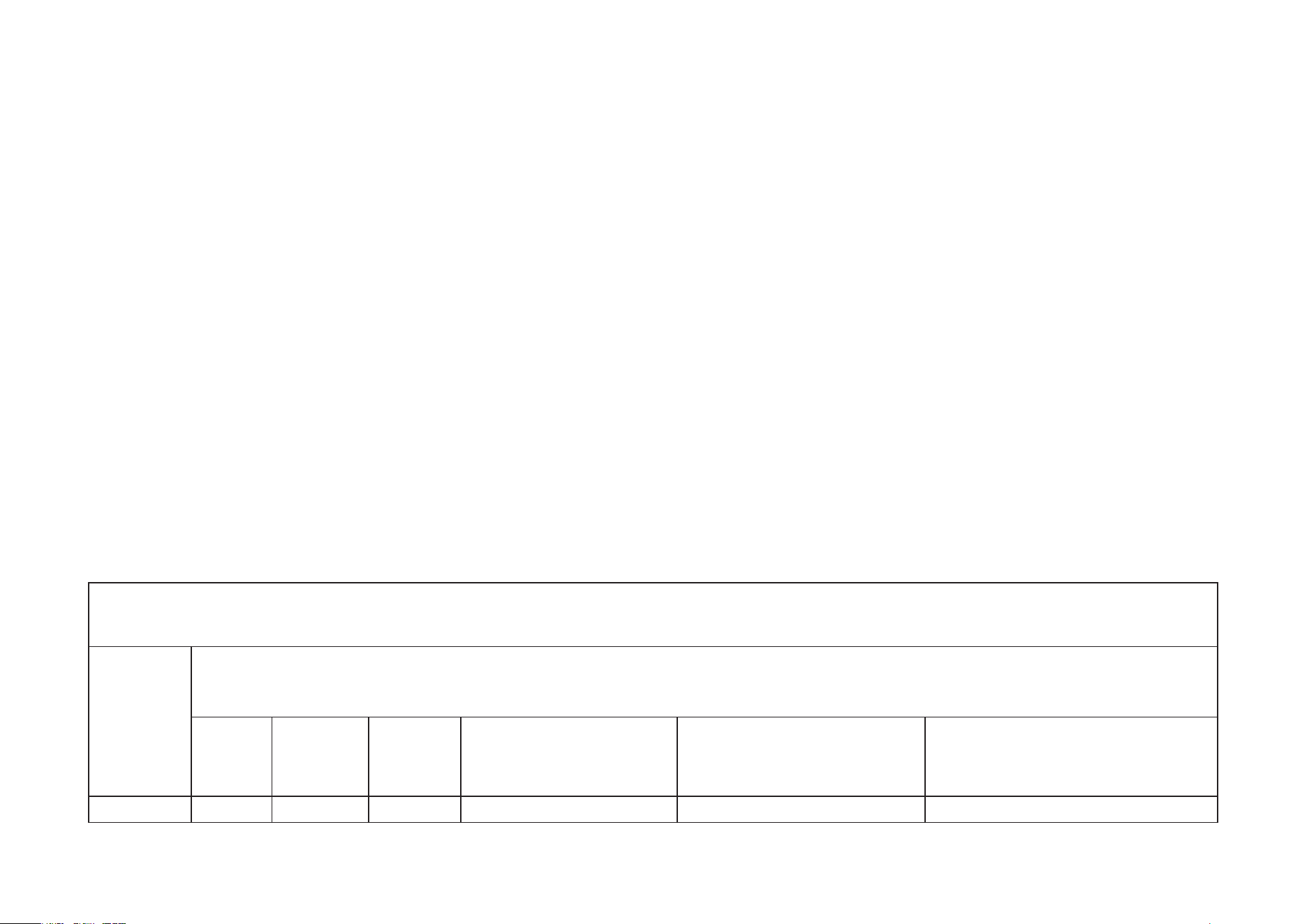
限用物質含有情況標示聲明書
設備名稱:戶外旋轉式防護 WiFi 攝影機 型號(型式):Tapo C510W
Equipment name Type designation (Type)
單元
Unit
限用物質及其化學符號
Restricted substances and its chemical symbols
鉛
Lead
(Pb)
汞
Mercury
(Hg)
鎘
Cadmium
(Cd)
六價鉻
Hexavalent chromium
(Cr
+6
)
多溴聯苯
Polybrominated biphenyls
(PBB)
多溴二苯醚
Polybrominated diphenyl ethers
(PBDE)
PCB ○ ○ ○ ○ ○ ○
21
外殼 ○ ○ ○ ○ ○ ○
電源供應器 − ○ ○ ○ ○ ○
塑膠組件 ○ ○ ○ ○ ○ ○
備考 1.〝超出 0.1 wt %〞及〝超出 0.01 wt %〞係指限用物質之百分比含量超出百分比含量基準值
Note 1:“Exceeding 0.1 wt %” and “exceeding 0.01 wt %” indicate that the percentage content of the restricted substance
exceeds the reference percentage value of presence condition.
備考 2.〝○〞係指該項限用物質之百分比含量未超出百分比含量基準值。
Note 2:“○” indicates that the percentage content of the restricted substance does not exceed the percentage of reference value
of presence.
備考 3.〝−〞係指該項限用物質為排除項目。
Note 3:The “−” indicates that the restricted substance corresponds to the exemption.
Продукт сертифіковано згідно с правилами системи УкрСЕПРО на відповідність вимогам нормативних документів та вимогам,
що передбачені чинними законодавчими актами України.

22
Safety Information
• Keep the device away from fire or hot environments. DO NOT immerse in water or any other liquid.
• Do not attempt to disassemble, repair, or modify the device. If you need service, please contact us.
• Do not use damaged charger or USB cable to charge the device.
• Do not use any other chargers than those recommended
• Do not use the device where wireless devices are not allowed.
• Adapter shall be easily accessible.
• Use only power supplies which are provided by manufacturer and in the original packing of this product. If you have any questions, please don’t
hesitate to contact us.
• Adapter should be used indoors where the ambient temperature is lower than or equal to 40ºC.
• This product uses radios and other components that emit electromagnetic fields. Electromagnetic fields and magnets may interfere with pacemakers
and other implanted medical devices. Always keep the product and its power adapter more than 15 cm (6 inches) away from any pacemakers or
other implanted medical devices. If you suspect your product is interfering with your pacemaker or any other implanted medical device, turn off
your product and consult your physician for information specific to your medical device.
• Operating Temperature: -30 ºC ~ 60 ºC (-22°F ~ 140°F )
• Adapter should be used indoors where the ambient temperatureis lower than or equal to 40°C.
Please read and follow the above safety information when operating the device. We cannot guarantee that no accidents or damage will occur due to
improper use of the device. Please use this product with care and operate at your own risk.
23
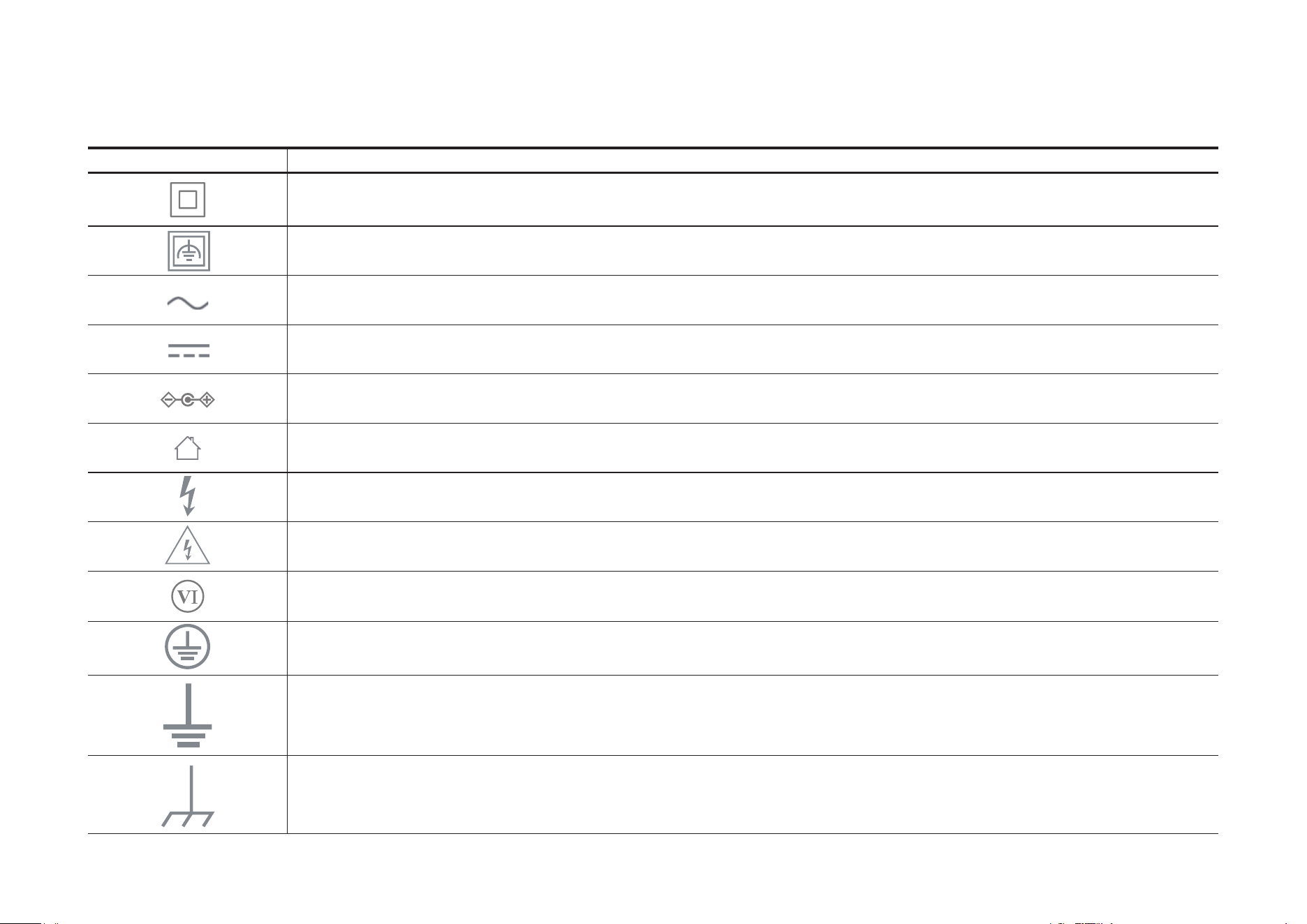
Explanation of the symbols on the product label
Symbols may vary from products.
Symbol Explanation
Class II equipment
Class II equipment with functional earthing
Alternating current
DC voltage
Polarity of output terminals
Indoor use only
Dangerous voltage
Caution, risk of electric shock
Energy efficiency Marking
Protective earth
Earth
Frame or chassis
24
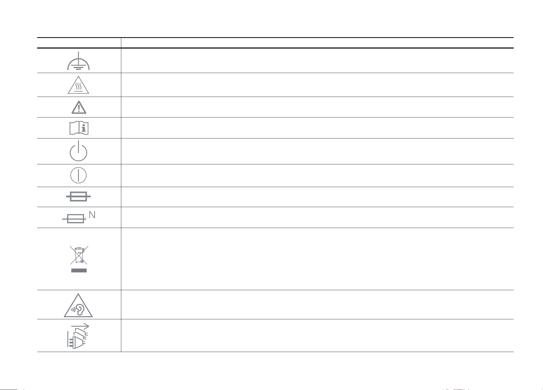
Symbol Explanation
Functional earthing
Caution, hot surface
Caution
Operator’s manual
Stand-by
“ON”/”OFF” (push-push)
Fuse
Fuse is used in neutral N
RECYCLING
This product bears the selective sorting symbol for Waste electrical and electronic equipment (WEEE). This means
that this product must be handled pursuant to European directive 2012/19/EU in order to be recycled or dismantled to
minimize its impact on the environment.
User has the choice to give his product to a competent recycling organization or to the retailer when he buys a new
electrical or electronic equipment.
Caution, avoid listening at high volume levels for long periods
Disconnection, all power plugs

25
Symbol Explanation
m Switch of mini-gap construction
µ
Switch of micro-gap construction (for US version)
Switch of micro-gap / micro-disconnection construction (for other versions except US)
ε Switch without contact gap (Semiconductor switching device)