54-49-1605
SERVICE PARTS LIST
BULLETIN NO.
MILWAUKEE TOOL
l
www.milwaukeetool.com
13135 W. LISBON RD., BROOKFIELD, WI 53005
Drwg. 4
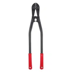
48-22-4014 14" Standard Bolt Cutter Page 1
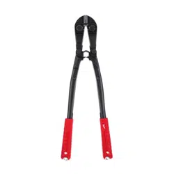
48-22-4018 18" Standard Bolt Cutter Page 2
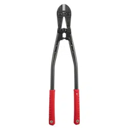
48-22-4024 24" Standard Bolt Cutter Page 3
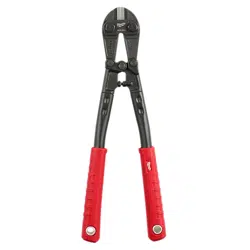
48-22-4031 30" Standard Bolt Cutter Page 4
BOLT CUTTERS
Sept. 2021
REVISED BULLETIN
DATE
CATALOG NO.
SPECIFY CATALOG NO. AND SERIAL NO. WHEN ORDERING PARTS
48-22-4114 14" Premium Bolt Cutter Page 5
48-22-4124 24" Premium Bolt Cutter Page 6
48-22-4218
18" Non-Conductive Bolt Cutter
Page 7
48-22-4224
24" Non-Conductive Bolt Cutter
Page 8
1
4
10
11
14
5
(3x)
3 5
10 11
16
3
(3x)
EXAMPLE:
Component Parts (Small #) Are Included
When Ordering The Assembly (Large #).
0
00
FIG. PART NO. DESCRIPTION OF PART NO. REQ.
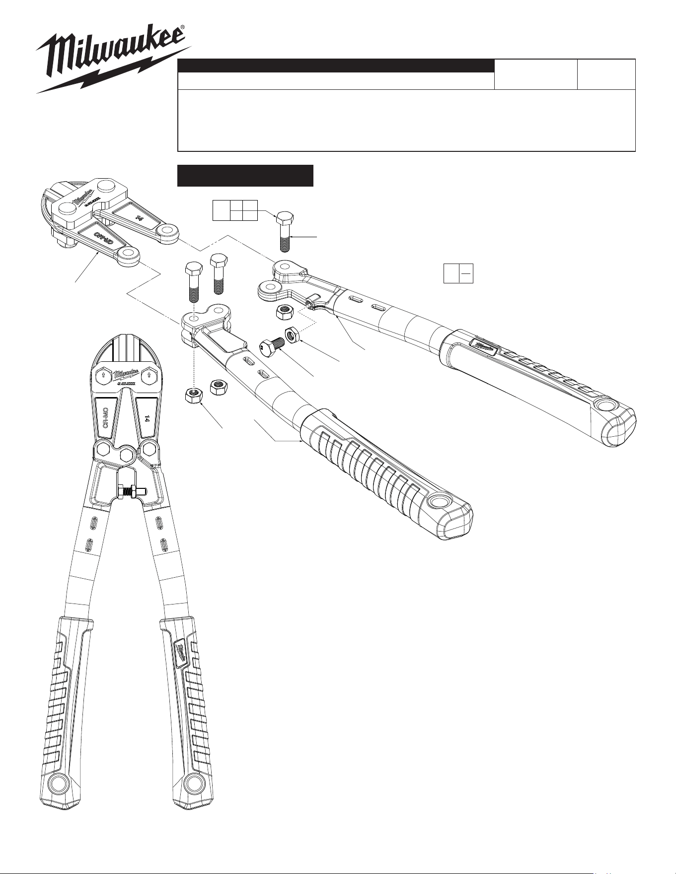
1 48-38-0014 14" Cutter Blade Assembly (1)
3 --------------- Hex Nut (3)
4 --------------- 14" Handle Assembly-Left (1)
5 --------------- Hinge Bolt (3)
10 --------------- Adjustment Bolt (1)
11 --------------- Adjustment Hex Nut (1)
14 --------------- 14" Handle Assembly-Right (1)
16 14-46-2135 Hardware Kit (1)
14" Standard Bolt Cutter No. 48-22-4014
SEE PAGE 9 FOR PROCEDURE
TO ADJUST THE JAW
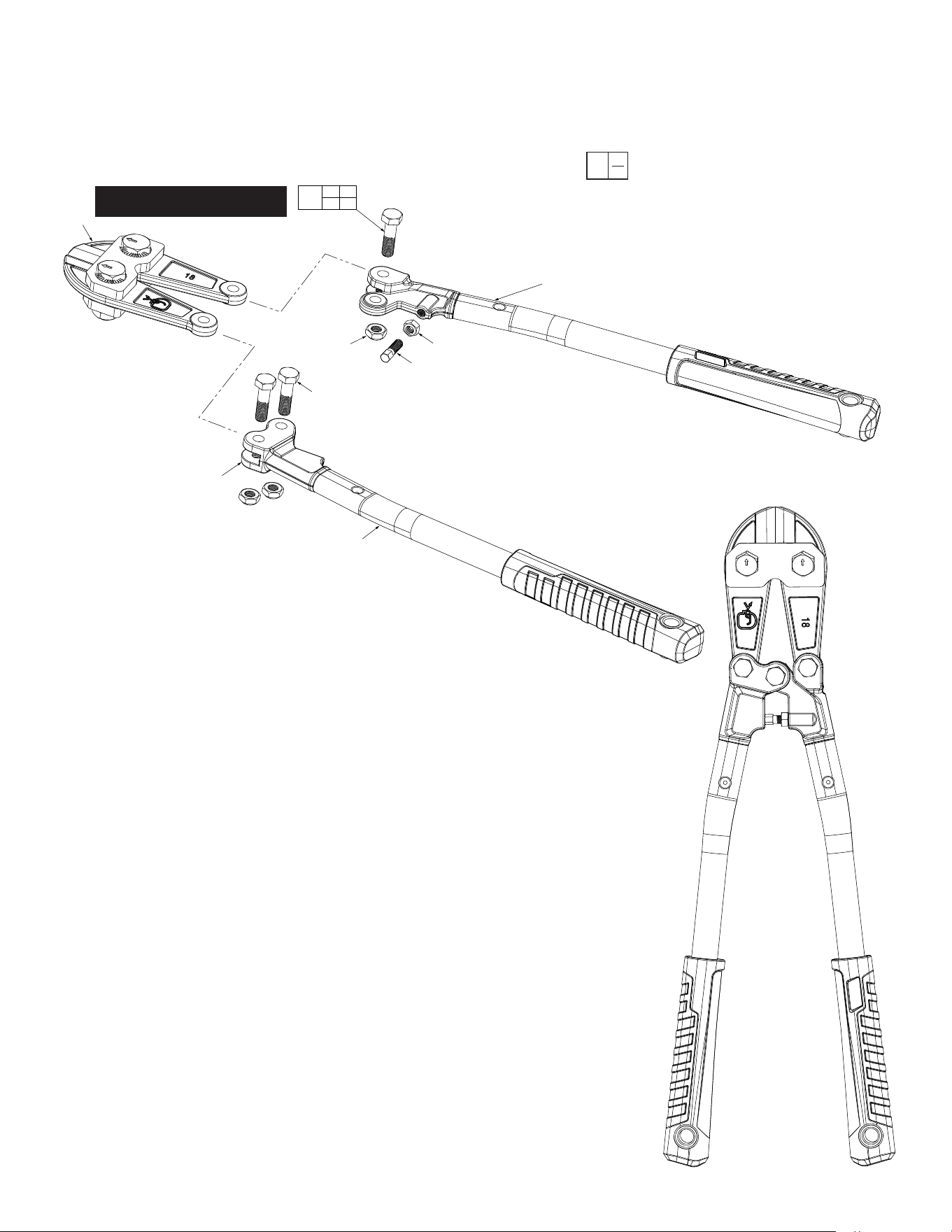
FIG. PART NO. DESCRIPTION OF PART NO. REQ.
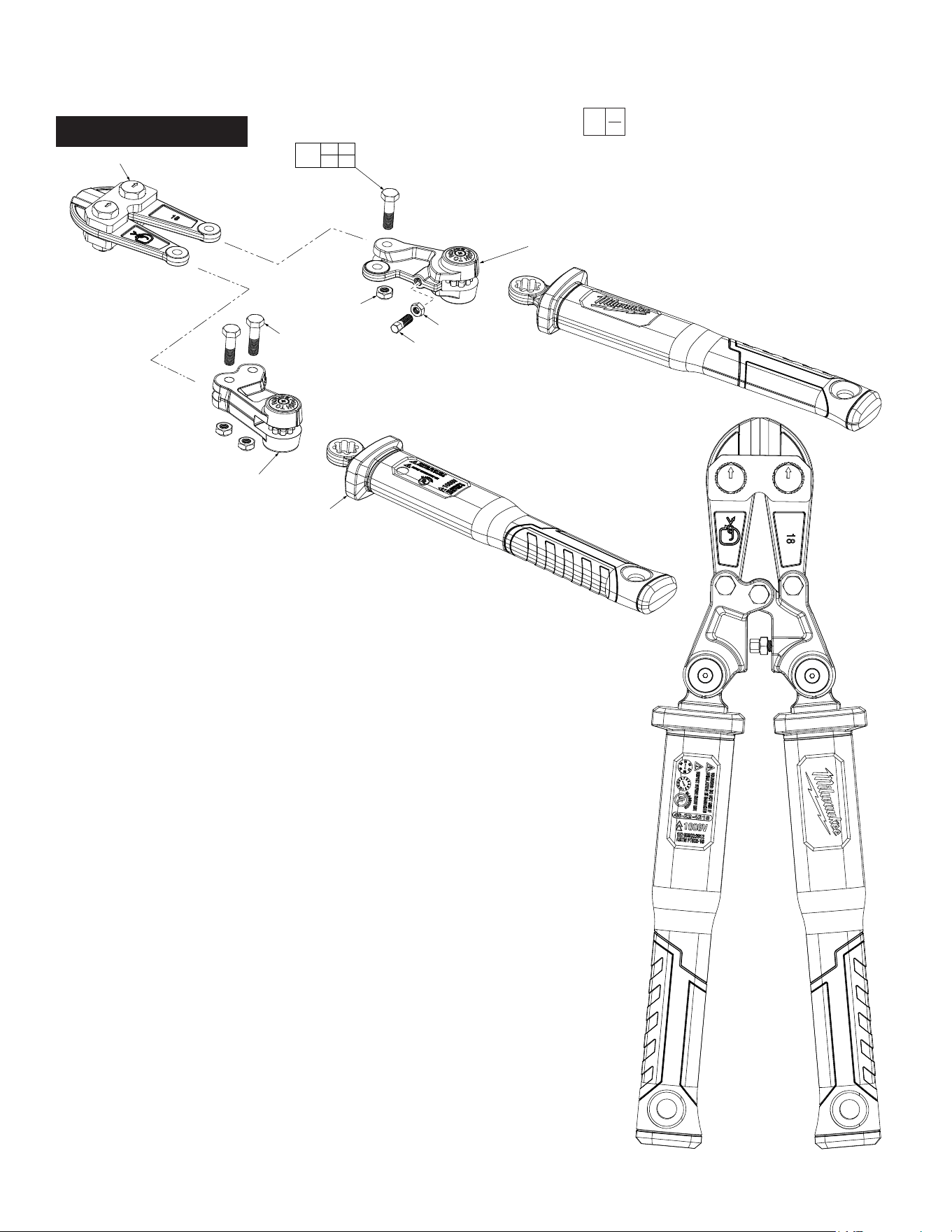
1 --------------- Handle Assembly (2)
4 --------------- Adjustment Hex Nut (1)
5 --------------- Adjustment Bolt (1)
6 --------------- Hinge Bolt (3)
7 --------------- Right Bolt Cutter Pivot Assembly (1)
8 --------------- Lock Nut (3)
9 --------------- Left Bolt Cutter Pivot Assembly (1)
10 48-38-0018 18" Cutter Blade Assembly (1)
16 14-46-2139 Hardware Kit (1)
EXAMPLE:
Component Parts (Small #) Are Included
When Ordering The Assembly (Large #).
0
00
18" Standard Bolt Cutter No. 48-22-4018
10
16
4 5
6 8
7
5
4
8
(x3)
6
(x3)
9
1
SEE PAGE 9 FOR PROCEDURE
TO ADJUST THE JAW
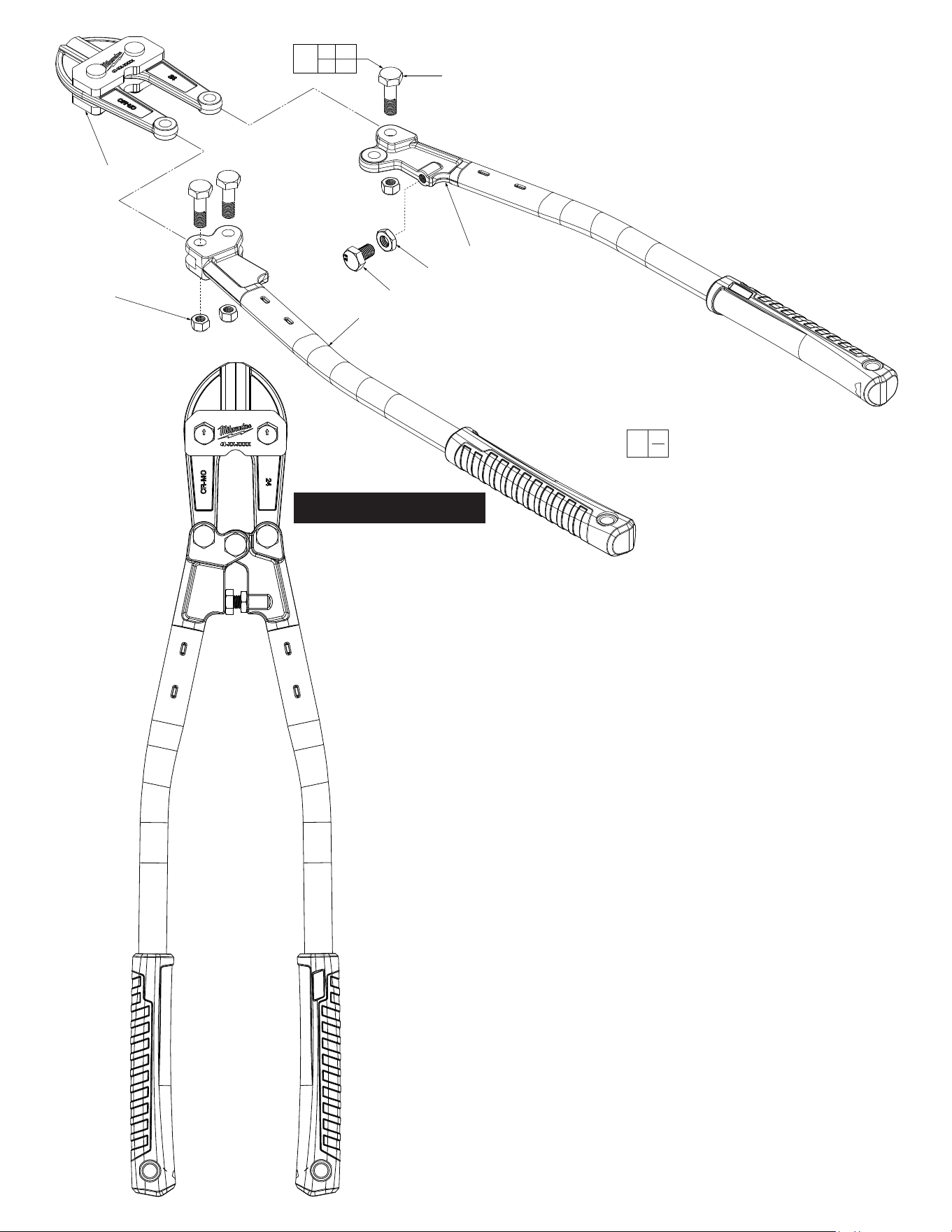
FIG. PART NO. DESCRIPTION OF PART NO. REQ.
1 48-38-0024 24" Cutter Blade Assembly (1)
3 --------------- Hex Nut (3)
4 --------------- 24" Handle Assembly-Left (1)
5 --------------- Hinge Bolt (3)
10 --------------- Adjustment Bolt (1)
11 --------------- Adjustment Hex Nut (1)
14 --------------- 24" Handle Assembly-Right (1)
16 14-46-2140 Hardware Kit (1)
EXAMPLE:
Component Parts (Small #) Are Included
When Ordering The Assembly (Large #).
0
00
24" Standard Bolt Cutter No. 48-22-4024
1
3
(3x)
4
10
11
14
5
(3x)
3 5
10 11
16
SEE PAGE 9 FOR PROCEDURE
TO ADJUST THE JAW
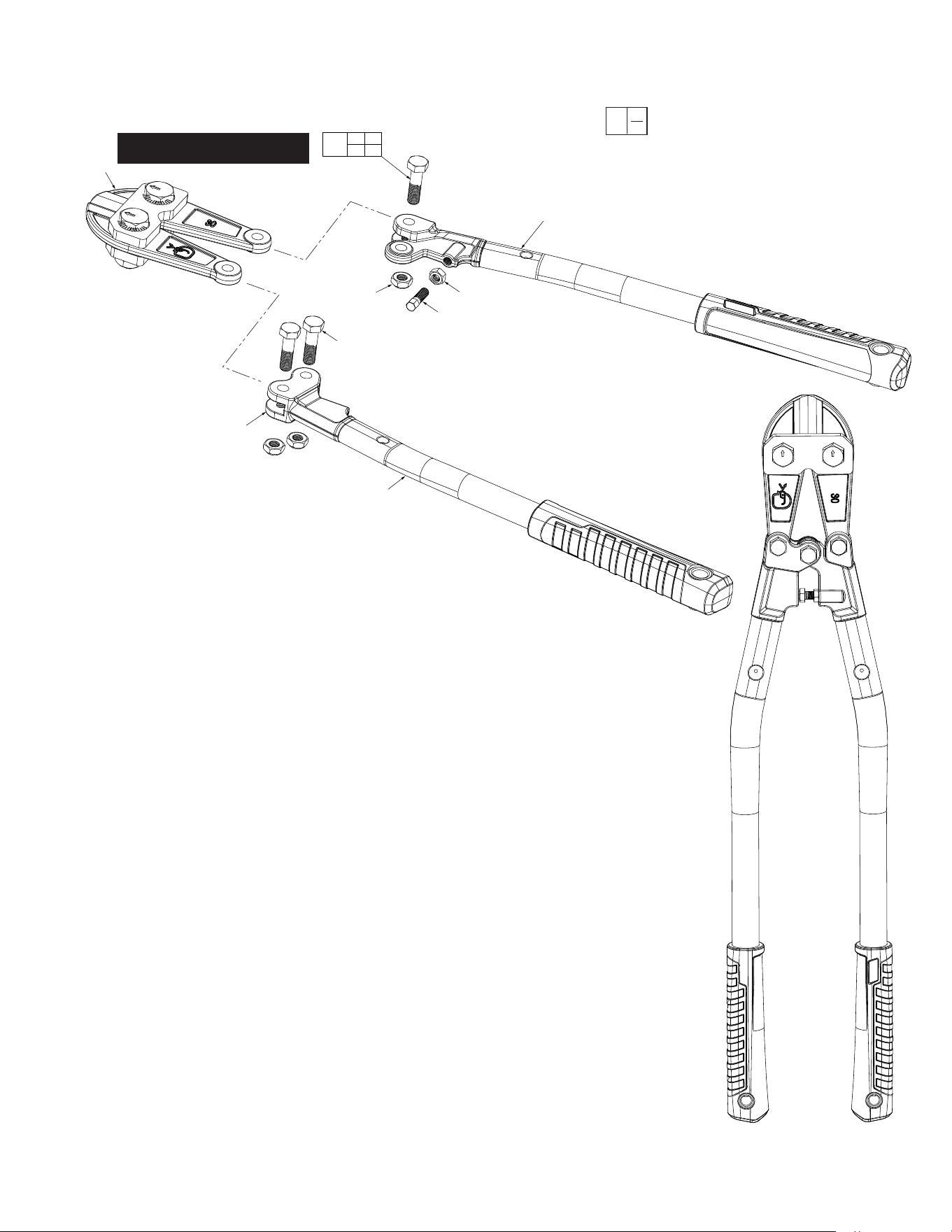
FIG. PART NO. DESCRIPTION OF PART NO. REQ.
1 --------------- Handle Assembly (2)
4 --------------- Adjustment Hex Nut (1)
5 --------------- Adjustment Bolt (1)
6 --------------- Hinge Bolt (3)
7 --------------- Right Bolt Cutter Pivot Assembly (1)
8 --------------- Lock Nut (3)
9 --------------- Left Bolt Cutter Pivot Assembly (1)
10 48-38-0031 30" Cutter Blade Assembly (1)
16 14-46-2149 Hardware Kit (1)
EXAMPLE:
Component Parts (Small #) Are Included
When Ordering The Assembly (Large #).
0
00
30" Standard Bolt Cutter No. 48-22-4031
10
16
4 5
6 8
7
5
4
8
(x3)
6
(x3)
9
1
SEE PAGE 9 FOR PROCEDURE
TO ADJUST THE JAW
EXAMPLE:
Component Parts (Small #) Are Included
When Ordering The Assembly (Large #).
0
00
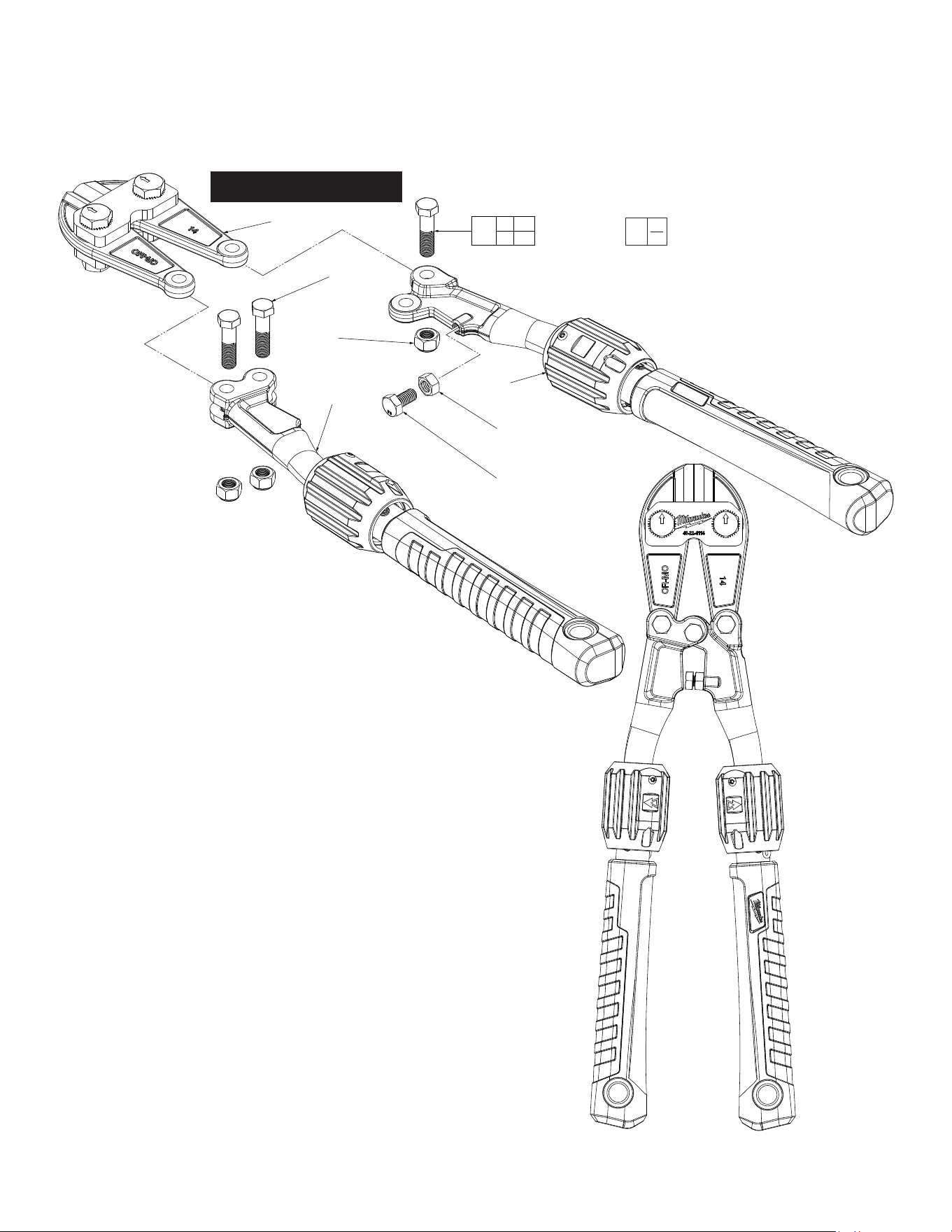
FIG. PART NO. DESCRIPTION OF PART NO. REQ.
1 48-38-0014 14" Cutter Blade Assembly (1)
3 --------------- Hex Nut (3)
4 --------------- 14" Adjustable Handle Assembly-Left (1)
5 --------------- Hinge Bolt (3)
10 --------------- Adjustment Bolt (1)
11 --------------- Adjustment Hex Nut (1)
14 --------------- 14" Adjustable Handle Assembly-Right (1)
16 14-46-2135 Hardware Kit (1)
14" Premium Bolt Cutter No. 48-22-4114
5
(3x)
3
(3x)
4
14
11
10
1
3 5
10 11
16
SEE PAGE 9 FOR PROCEDURE
TO ADJUST THE JAW
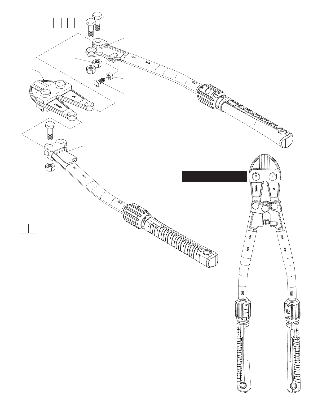
FIG. PART NO. DESCRIPTION OF PART NO. REQ.
1 48-38-0024 24" Cutter Blade Assembly (1)
3 --------------- Hex Nut (3)
4 --------------- 24" Adjustable Handle Assembly-Left (1)
5 --------------- Hinge Bolt (3)
10 --------------- Adjustment Bolt (1)
11 --------------- Adjustment Hex Nut (1)
14 --------------- 24" Adjustable Handle Assembly-Right (1)
16 14-46-2140 Hardware Kit (1)
EXAMPLE:
Component Parts (Small #) Are Included
When Ordering The Assembly (Large #).
0
00
24" Premium Bolt Cutter No. 48-22-4124
5
(3x)
14
10
11
3
(3x)
1
4
3 5
10 11
16
SEE PAGE 9 FOR PROCEDURE
TO ADJUST THE JAW
EXAMPLE:
Component Parts (Small #) Are Included
When Ordering The Assembly (Large #).
0
00
16
4 5
6 8
10
8
(x3)
5
9
6
(x3)
1
4
7
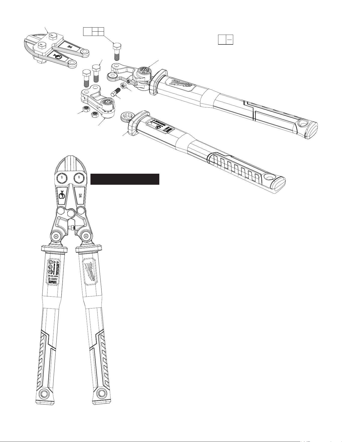
FIG. PART NO. DESCRIPTION OF PART NO. REQ.
1 --------------- Handle Assembly (2)
4 --------------- Adjustment Hex Nut (1)
5 --------------- Adjustment Bolt (1)
6 --------------- Hinge Bolt (3)
7 --------------- Right Bolt Cutter Pivot Assembly (1)
8 --------------- Lock Nut (3)
9 --------------- Left Bolt Cutter Pivot Assembly (1)
10 48-38-0018 18" Cutter Blade Assembly (1)
16 14-46-2139 Hardware Kit (1)
18" Non-Conductive Bolt Cutter No. 48-22-4218
SEE PAGE 9 FOR PROCEDURE
TO ADJUST THE JAW
EXAMPLE:
Component Parts (Small #) Are Included
When Ordering The Assembly (Large #).
0
00
24" Non-Conductive Bolt Cutter No. 48-22-4224
16
4 5
6 8
10
8
(x3)
5
9
6
(x3)
1
4
7
FIG. PART NO. DESCRIPTION OF PART NO.
REQ.
1 --------------- Handle Assembly (2)
4 --------------- Adjustment Hex Nut (1)
5 --------------- Adjustment Bolt (1)
6 --------------- Hinge Bolt (3)
7 --------------- Right Bolt Cutter Pivot Assembly (1)
8 --------------- Lock Nut (3)
9 --------------- Left Bolt Cutter Pivot Assembly (1)
10 48-38-0025 24" Cutter Blade Assembly (1)
16 14-46-2141 Hardware Kit (1)
SEE PAGE 9 FOR PROCEDURE
TO ADJUST THE JAW
1
2
3
4
4
5 6
7
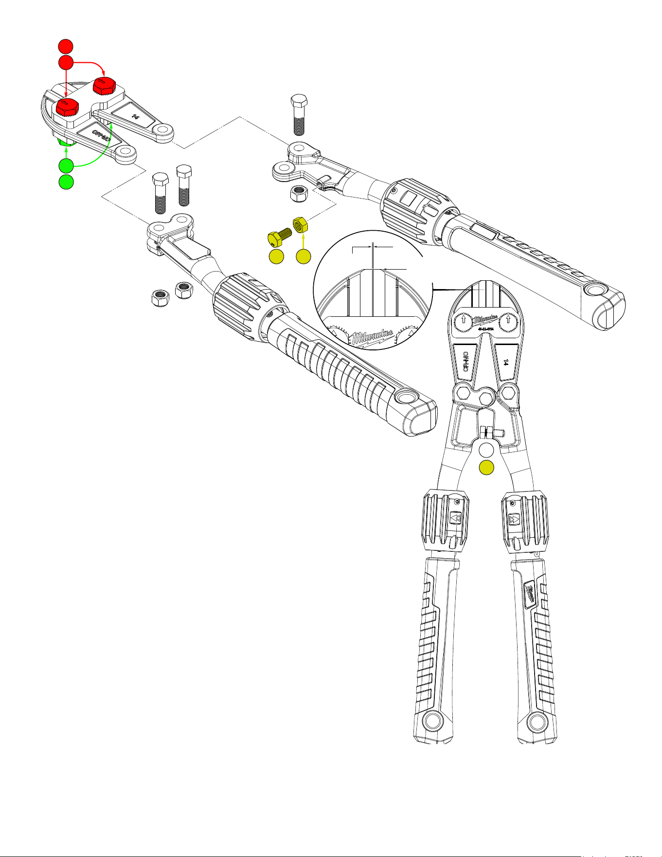
Parallel
Even (aligned)
as close as
possible
1. Loosen the nuts (in green), two places.
2. Close the handles completely.
3. Turn/index each bolt (in red) such that the cutting
edges of the blades are parallel and just touch, being
sure the tips of the blades are also even. You may have to
slightly open the handles to correctly position the jaws.
4. Tighten the green nut while securing the red bolt, as to retain
its position, two places.
5. Adjust the yellow bolt to provide mechanical stop consistant
with jaw touch.
6. Tighten yellow jam nut while securing yellow bolt to retain its
position.
7. Verify that yellow bolt provides mechanical stop consistant when
jaws touch. NOTE: It is desirable to provide a slight gap as
opposed to jaws compressing cutting edges which may result in
damage to the jaws, etc. Bolt cutters may not be the ideal tool
to cut razor wire and other thin material.
JAW ADJUSTMENT PROCEDURE
Bolts (in red) have non-concentric rings on shanks which allow
jaw adjustment. Use the following procedure to adjust jaws so
cutting edges almost touch (parallel) and tips are even (aligned)
as close as possible when handles are closed.
Model 48-22-4114 Shown