Quanrum
=aeQO
GAS-FIRED,
DIRECT
VENT,
CONDENSING,
HOT
WATER
BOILER
INSTALLATION,
OPERATION
&
MAINTENANCE
MANUAL
SE
DUNKIRK
BOILERS
85
Middle
Rd.
Dunkirk,
NY 14048
www.dunkirk.com
P/N#
14683301,
Rev.
C
[12/2010]
50-100
GAS-FIRED
B
Model
No.
90-50
90-75
90-100
US
ENERGY
STAR
|
These
instructions
must
be
affixed
on
or
adjacent
to
the
boiler.
WARNING
Improper
installation,
adjustment,
alteration,
A
service,
or
maintenance
can
cause
injury
or
property
damage.
Refer
to
this
manual.
For
assistance
or
additional
information
consult
a
qualified
installer,
service
agency,
or
the
gas
supplier.
CAUTION
Ay
Read
all
instructions
carefully
before
starting
the
installation.
Save
this
manual
for
reference.
TABLE
OF
CONTENTS
Warnings
and
Safety
SYMDOIS
......cccccccc
cece
en ne
seen ence
ee
eee
e
eee
ee
EEE
EEE
EEA
A
EEE
AEEAEE
OSES
ESSE
EEE
E
SEE
SSDS
SEES
EES
SEES
EEE
EEE
SEES
3
IMCrOGUCCION..
2.
e
cece
cece
cnet
e
ee
eee
rene
een
A
nae
EEE
EAA
EO
ene
EEA
EEE EEA
ena
ene
nA
era ene ans
eae
cates
ena
e
ene
naan
eneeaaeneeannaees
4
Boller
RatingS
&
CaPacitieS
......ccccecccecce
cence
nena
tent
eee
n
eee
A
EEO
A
EEE EEE
TEESE
EEE EDEL
ED
AEE
ESSE ESSE
EEE
E
SESE
EES
SEES
ESSERE
EEE
EES
5
Boilers
For
Use
At
High
AILiICUCS
2...
ccc
cece
scene
cent
enn
e
eee
e
eee
e
ne
EEE
EEE
EEE
EEE
EEE
ED
AEE
E
SSG
SESE
SEES
SEES
EES EEE
SESE
EEE
EERE
ES
6
Rules
For
Safe
Installation
ANd
Operation
2.0...
ccc
cccccccese
ence
ence
eee eee
eee
eee
ene
EA
EG AE EG
AEG
E
SEES
SEES
ESSE
DEEDES
EEE EEE
EES
8
Before
Installing
The
Boller
........cccccccecce
scence
ene
eee
eee
e
ene
e
eee eee
e
ee
eee EEO
EERE
EEE
EEE
ED
EEE
ESSE
EEE
E
SEES
SESE
EES
SEES ESE EEE
EEE
EES
8
PIACING
TNE
BOUOr
......ccccccc
cece
ence
eee
e
eee
eee
eee
en
A
EAA
EGA
E
EGA EEE
SEES EEE
E
DEEDES
EEE
E
ADELE
ESTEE
EEE
ASSESSES
EES
SESE
SEES
ESSE
EE
EEE
SEES
il
Ne@ar
Boller
PIDING
........cccccceccencc
cece
eee
eee
nee
eee
n
enn
A
AEG
A
EEG
AEEE
EEE
SEES
CEES
DEEL
EEE
EE
EEDA SEGA
ED
EASES
EEE
EEES SESE
ESSE
DEEDES
EEE
SEES
12
Combustion
Air
and
V@nt
PIPE
20...
cesses
cece
esse
ence
eens
eee
ee
eee
ERA
EEE
EEDA
EEE
A
EEA
EE
SEES
SEES
EEE
E
SEES
SEES
ESSE
DEEDES
EEE EEE EEE
19
GAS
SUPPLY
PIDING.....ccccccce
csc
ene
cee
ence
eee
eee
e
ee
ERA
ERASED
AEE
GAEDE
EEDA SEES
EEE
EEE
EEE
EEE
EEE
SEE
EDE
SSD AED
ESSE
EE ES
SEES
SEES
OSES
EE
EEE
EEE
24
EI@CtriCal
WIrTNG
.....
ccc
ccccsc
cence
cence eee
tent
ene
A
AGA
E
AGA
EE EE EE
EEE
A
EEO
E
EOE
E
DEED
REEDS
E
EEE EEE
SEGA
SDSS
SDE
E
EEE
EES
SEES
ESSE
DEEDES
EEE
SEES
26
Controls
and
ACCESSOFICS
2.0...
..cccece
cee
ce
eect
ence
eee
e
eee
ena
e
ne
ene
naan
a
ened nena
ence
ne
esata
eeeenaeneenetaenaeneneetaenaeeetaaea
30
Water
Treatment
&
Freeze
Protection
2.2...
....ccccee
cece
ence
cea
c
eee
cena
eee ene
na
ena
eee
nesta
eeaenetaeeseeeeeaeeeeenaetaeeenges
32
De)
|
©
34
Operating
INSEUCTIONS.
........
cece cecc
ence
eee
eee
e
een
nee
nA
AEA
EAA
A
EGA
E
EEE EEE
EEE
EEO
EE
EEE
DEES
E
EEE EEE SEG AEG
DEEDES
ES
SEES
SEES
ESSE
SEER
EES
35
To
Turn
OFF
GAS
TO
ADDHANCE
2...
cece
ccc cee
ence
nee
eee
n
nent
eee
e
nae EEE EEE
E
EEE
EEE
EEE
SEALE
AS
ES
AEDES
SESE
EDS EES EEE
E
ESSE
ESSE
EE
EEE
EES
35
Check
Out
Procedure
and
ACjUSKMENE
20...
..cccccccces
cece
seen
ee
eee
eee
ee EE
EAE
EE
EAE
A
EEA
S
EGA
ES
SEES
AE ED
SEES
EEE
ESSE
SESE
EEE
E
EEE
36
Installation
and
Check-Out
Certificate.
.....
00...
ce
ccce cece
cece
e
eee
cena
eee
nena
eta
eee
ene
eae
ea
eeeenaeeeeeeneenaenetaetaeeeeneeae
ea
40
Maintenance
ANd
CI@ANing
......cccecceccc
cece
nee
ee
een
tent
ena
e
nate
aed
EO
ESOS CEES
DEEL
EE
EEE
E
EEE
SS
AEGE
SSE AES
ESSE
SEES
SEES CEES
ESSE
EEE
EEES
41
Detailed
Sequence
Of
ODEration
......cccccccccccsscecsaceaeeeeeeeaeeaeseeae
eee
eeeaeeaeeesaeeaeeeaeeaseasaaegaeetaaesaeensaeeagea
44
TrOUDIGSNOOLING.......cccccecc
ence
eee
ene
e
enn
e
ene
A
na
AEA
A
ASAE
EEDA
EEE
EEE
SEES
EEE
EERE
EEE
E
EEE
EE
ASDA
EASA
ESAS
ED
EEES SEES
SEES
ESSERE
EES
SEES
EEE
SEES
47
Differential
Air
Pressure
Switch
Check
..........ceccce
ccc
ee
eee
ee
eect
acne
eee
teeta
ene ene eae
ee
eeaedaeneneenaegaenetaeeseeeeeaene
ees
55
IMPORTANT:
THIS
MANUAL
MUST
BE
KEPT
NEAR
THE
BOILER
FOR
FUTURE
REFERENCE!!
WARNINGS
AND
SAFETY
SYMBOLS
Indicates
an
imminently
hazardous
situation
A
Indicates
an
imminently
hazardous
situation
which,
if
not
avoided,
WILL
result
in
death,
which,
if
not
avoided,
may
result
in
injury
or
serious
injury
or
substantial
property
damage.
property
damage.
WARNING
NOTICE
A
Indicates
an
imminently
hazardous
situation
Indicates
information
which
should
be
which,
if
not
avoided,
may
result
in
death,
followed
to
ensure
proper
installation
and
serious
injury
or
substantial
property
damage.
operation.
3
oe
et
eanee
HS
®
INTRODUCTION
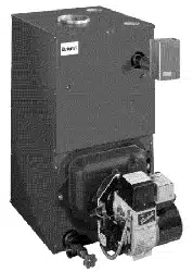
This
appliance
is
a
gas-fired
direct
vent
hot
water
boiler
with
cast
aluminum
boiler
sections.
A
revolutionary
cast
aluminum
heat
exchanger
means
better
heat
transfer
and
thermal
storage
than
similarly
sized
cast
iron
boilers,
which
results
in
higher
efficiency.
The
heating
system
water
absorbs
large
amounts
of
heat
from
the
cast
aluminum
heat
exchanger,
cooling
the
flue
gases
and
causing
condensation.
Sealed
combustion,
premix
gas
burner,
and
low flame
temperature
means
drastically
reduced
CO
and
NOx
emissions,
which
contribute
to
a
cleaner
and
healthier
environment.
This
appliance,
unlike
normal
residential
atmospheric
and
induced
draft
units,
takes
its
combustion
air
directly
from
the
outdoors
(sealed
combustion)
and
does
not
compete
with
building
occupants
for
fresh
air.
Sealed
combustion
(also
known
as
“direct
vent”)
is
the
safest
and
best
way
to
obtain plenty
of
clean
combustion
air.
The
induced
draft
fan
draws
in
the
outside
combustion
air,
then
takes
the
cooler
flue
gases
from
the
boiler
unit
and
provides
a
positive
removal
of
the
flue
gases
from
the
building
through
inexpensive
and
readily
available
PVC
and
CPVC
pipes.
NOTICE
IMPORTANT:
Read
the
following
instructions
COMPLETELY
before
installing!
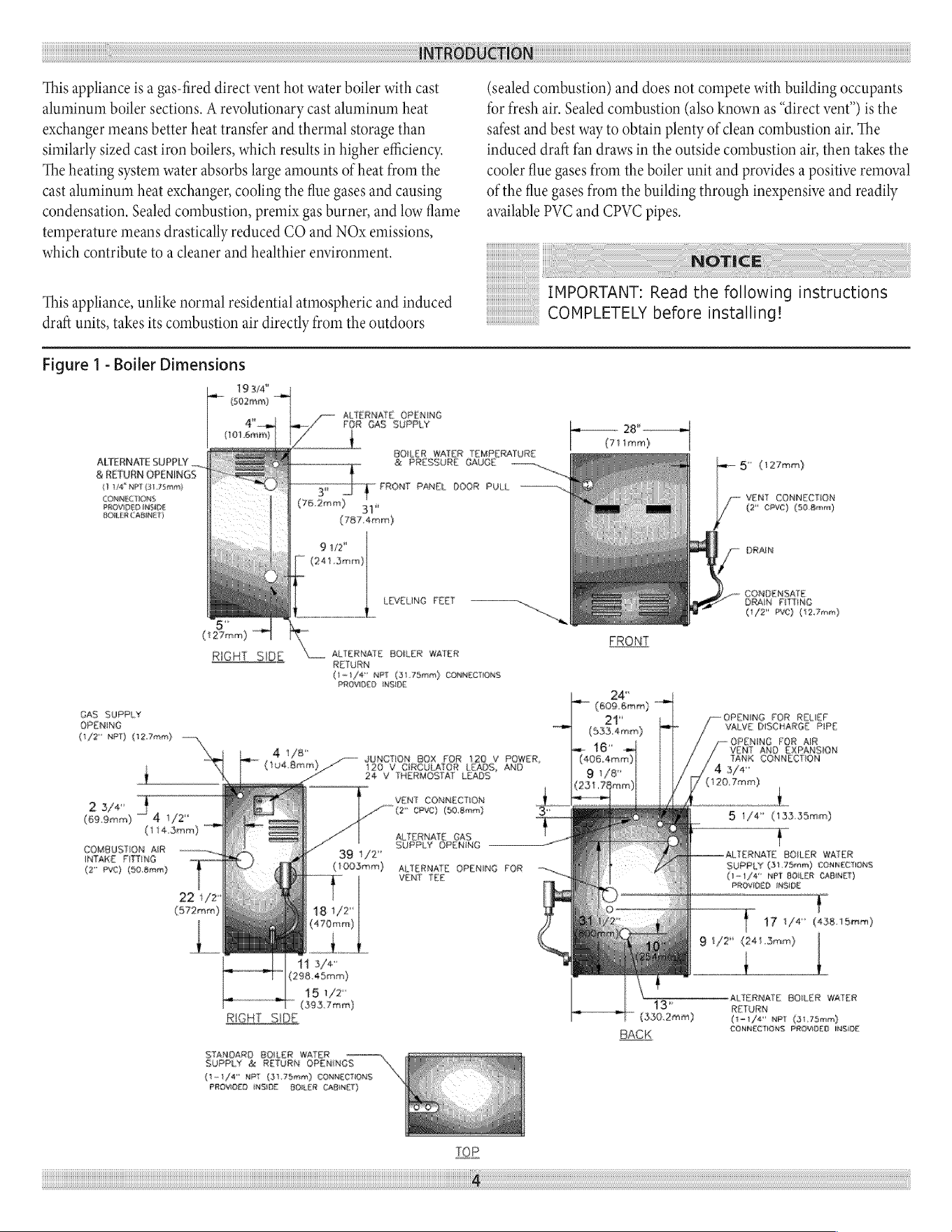
Figure
1 -
Boiler
Dimensions
19374"
(S02nim)
gs
(101
.6mm)
ALTERNATE
OPENING
FOR
GAS
SUPPLY
ALTERNATE
SUPPLY
__
&
PRESSURE
GAUGE
&
RETURN
OPENINGS
:
LEA”
NPT
GL?
Seca
ns
FRONT
PANEL
DOOR
FULL
COMMER
TIONS
.
PROVIDED
INSIDE
|
(782mm)
ye
BOILER
CABINET)
|
(787-4mm)
gure
(241.Smrm)
(12mm)
RIGHT
SIDE
ALTERNASTE
BOILER
WATER
RETURN
BOILER
WATER
TEMPERATURE
LEVELING
FEET
To
29°.
(71
ime)
—~
|
fy
fenen)
VENT
CONNECTION
(2°
CPYC)
{50
Benet}
DRAIN
a
CONDENSATE
GRAIN
FITTING
(1/2
PVE}
(12.
Fenen)
(ot
/d"
NPT
(31.
78men)
CONNECTIONS
PROVIDED
INSIDE
GAS
SUPPLY
OPENING
Cif)e"
MPT)
(12.
7reen)}
‘
__VENT
CONNECTION
‘i
Ser
(2*
CPVC)
(50.
8ramn}
(69.9)
44/2"
(114.3mm)
COMBUSTION
AIR
INTAKE
PITTING
(2°
PVC}
(40.
Beer)
AL
FERNATE
GAS
.
SUPPLY
OPENING
Oy
39
1/2"
(100Seirr)
VENT
TEE
11
3/4"
(298.
45rnm)
|.
18
1/2"
(393.
7mm)
RIGHT
SIDE
STANDARD
BOILER
WATER
SUPPLY
&
RETURN
OPENINGS
(1-1
/4"
NPT
(31,78men)
CONNECTIONS
PROVIDED
INSIDE
GOMER
Caginet)
JUNCTION
BOX
FOR
120
V
POWER,
120
V
CIRCULATOR
LEADS,
AND
24
¥
THERMOSTAT
LEADS
ALTERNATE
OPENING
FOR
24"
[~
(609.6rern)
OPENING
FOR
RELIEF,
VALVE
DISCHARGE
PIPE
OPENING
FOR
AIR
VENT
AND
EXPANSION
TANK
CONNECTION
at
(S33
4enen)
“5
1/4"
(133.35em)
ALTERNATE
BOILER
WATER
SUPPLY
(31.78rm)
CONNECTIONS
(i-t/@"
NPT
BOILER
CABINET)
PROVIDED
IMSIIE
Visa
91/2"
(241.
3mm)
(4.38,
15mm)
ALTERMATE
GCILER
WATER
13"
RETURN
(S50.2nrn)
(i1
fa"
NET
(317mm)
BACK
CONNECTIONS
PROMDEG
IMS
c
BOILER
RATINGS
&
CAPACITIES
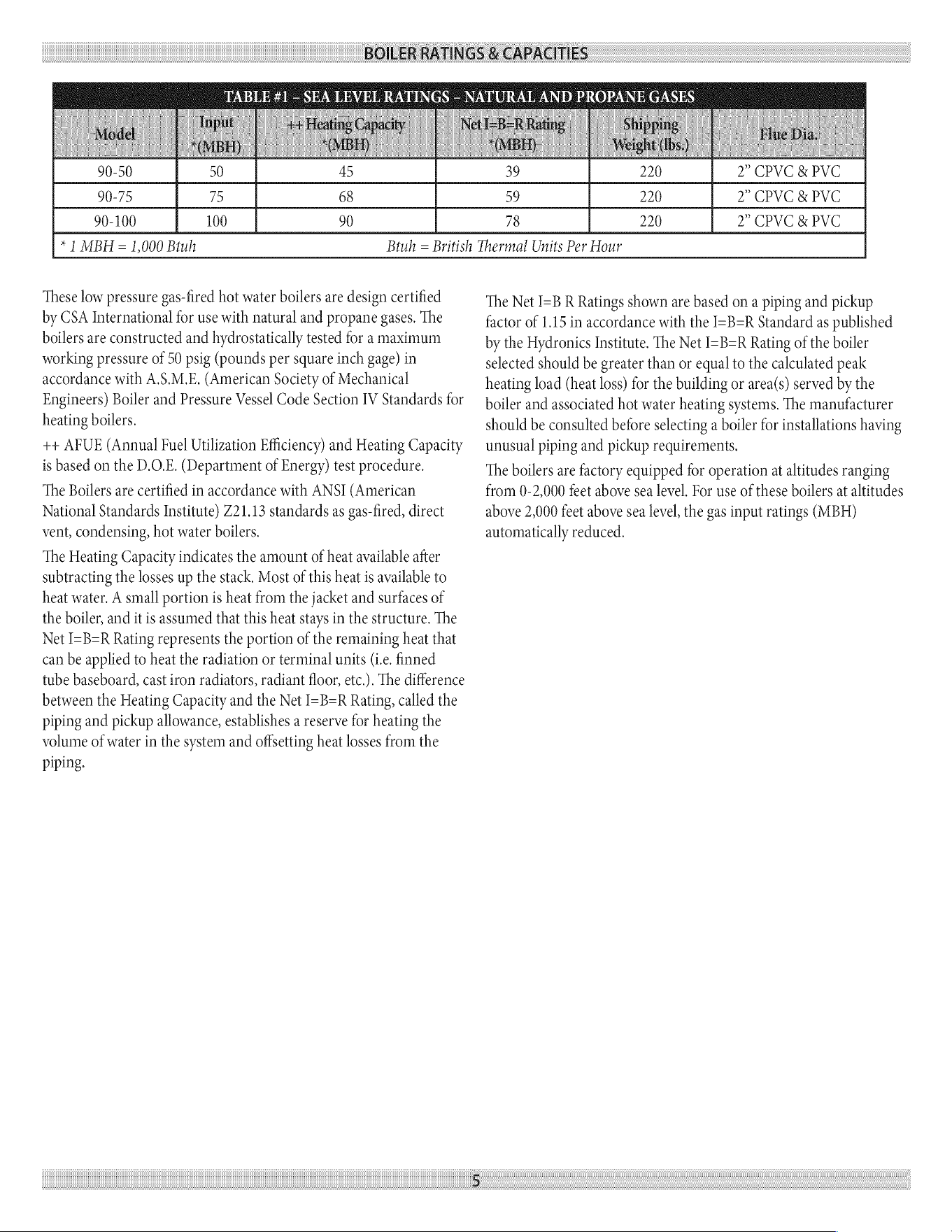
TABLE
#1
-
SEA
LEVEL
RATINGS
-
NATURAL
AND
PROPANE
GASES
90-50
50
45
39°
|
220
2?
CPVCKPVC
90-75
75
68 59
220
2°
CPVC
&
PVC
90-100
100
90 78
220
2°
CPVC
&
PVC
*
1
MBH
=
1,000
Btuh Btuh
=
British
Thermal
Units
Per
Hour
These
low
pressure
gas-fired
hot
water
boilers
are
design
certified
by
CSA
International
for
use
with
natural
and
propane
gases.
The
boilers
are
constructed
and
hydrostatically
tested
for
a
maximum
working
pressure
of 50
psig
(pounds
per
square
inch
gage)
in
accordance
with
A.S.M.E.
(American
Society
of
Mechanical
Engineers)
Boiler
and
Pressure
Vessel
Code
Section
IV
Standards
for
heating
boilers.
++
AFUE
(Annual
Fuel
Utilization
Efficiency)
and
Heating
Capacity
is
based
on
the
D.O.E.
(Department
of
Energy)
test
procedure.
The
Boilers
are
certified
in
accordance
with
ANSI
(American
National
Standards
Institute)
Z21.13
standards
as
gas-fired,
direct
vent,
condensing,
hot
water
boilers.
The
Heating
Capacity
indicates
the
amount
of
heat
available
after
subtracting
the
losses
up
the
stack.
Most
of
this
heat
is
available
to
heat
water.
A
small
portion
is
heat
from
the
jacket
and
surfaces
of
the
boiler,
and
it
is
assumed
that
this
heat
stays
in
the
structure.
The
Net
I=B=R
Rating
represents
the
portion
of
the
remaining
heat
that
can
be
applied
to
heat
the
radiation
or
terminal
units
(Le.
finned
tube
baseboard,
cast
iron
radiators,
radiant
floor,
etc.).
The
difference
between
the
Heating
Capacity
and
the
Net
I=B=R
Rating,
called
the
piping
and
pickup
allowance,
establishes
a
reserve
for
heating
the
volume
of
water
in
the
system
and
offsetting
heat
losses
from
the
piping.
The Net
I=B
R
Ratings
shown
are
based
on
a
piping
and
pickup
factor
of
1.15
in
accordance
with
the
I=B=R
Standard
as
published
by
the
Hydronics
Institute.
The
Net
I=B=R
Rating
of
the
boiler
selected
should
be
greater
than
or
equal
to
the
calculated
peak
heating
load
(heat
loss)
for
the
building
or
area(s)
served
by
the
boiler
and
associated
hot
water
heating
systems.
The
manufacturer
should
be
consulted
before
selecting
a
boiler
for
installations
having
unusual
piping
and
pickup
requirements.
The
boilers
are
factory
equipped
for
operation
at
altitudes
ranging
from
0-2,000
feet
above
sea
level.
For
use
of
these
boilers
at
altitudes
above
2,000
feet
above
sea
level,
the gas
input
ratings
(MBH)
automatically
reduced.
BOILERS
FOR
USE
AT
HIGH
ALTITUDE
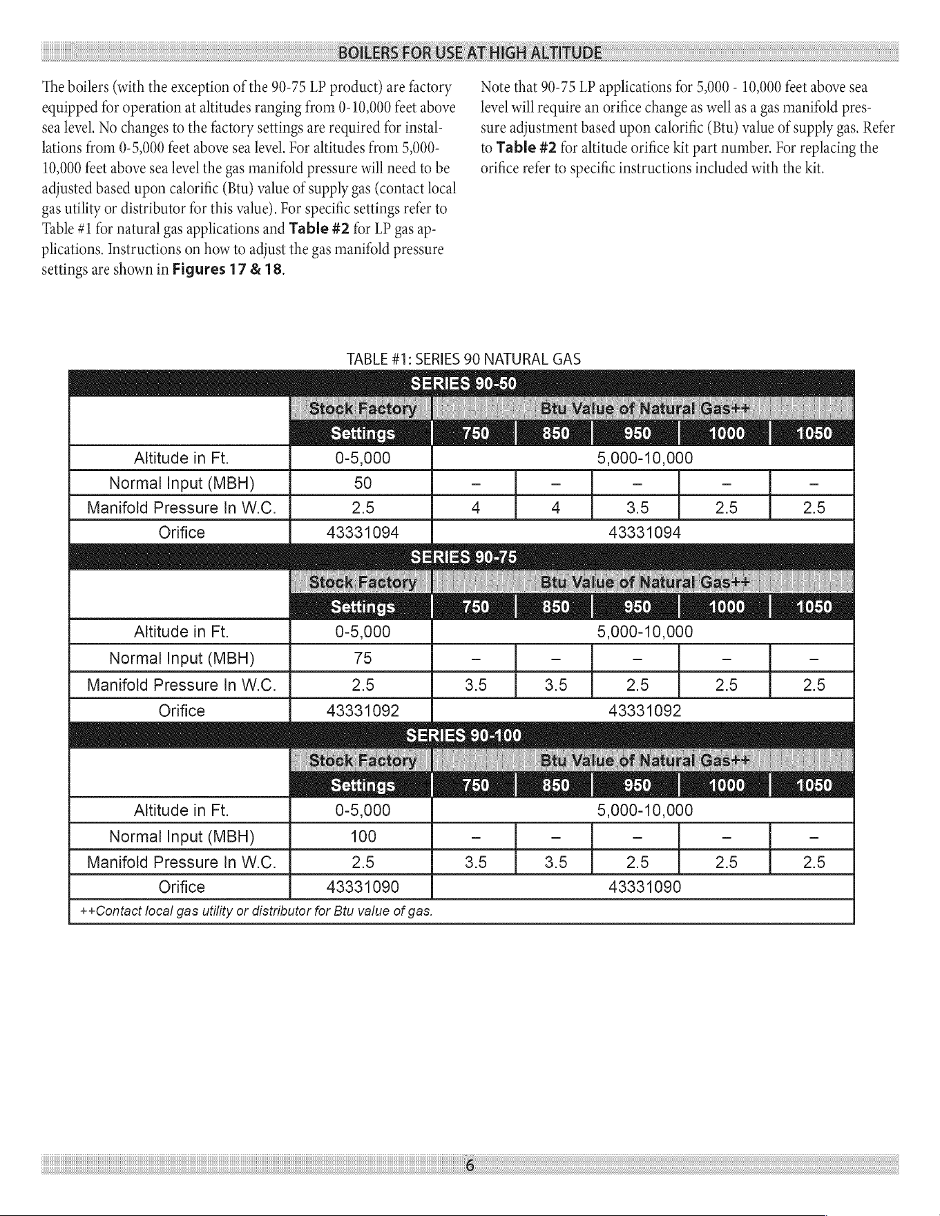
The
boilers
(with
the
exception
of
the
90-75
LP
product)
are
factory
equipped
for
operation
at
altitudes
ranging
from
0-10,000
feet
above
sea
level.
No
changes
to
the
factory
settings
are
required
for
instal-
lations
from
0-5,000
feet
above
sea
level.
For
altitudes
from
5,000-
10,000
feet
above
sea
level
the gas
manifold
pressure
will
need
to
be
adjusted
based
upon
calorific
(Btu)
value
of
supply
gas
(contact
local
gas
utility
or
distributor
for
this
value). For
specific
settings
refer
to
Table
#1
for
natural
gas
applications
and
Table
#2
for
LP
gas
ap-
plications.
Instructions
on
how
to
adjust
the
gas
manifold
pressure
settings
are
shown
in
Figures
17
&
18.
Note
that
90-75
LP
applications
for
5,000
-
10,000
feet
above
sea
level
will
require
an
orifice
change
as
well
as
a
gas
manifold
pres-
sure
adjustment
based
upon
calorific
(Btu)
value
of
supply
gas.
Refer
to
Table
#2
for
altitude
orifice
kit
part
number.
For
replacing
the
orifice
refer
to
specific
instructions
included
with
the
kit.
TABLE
#1:
SERIES
90
NATURAL
GAS
SERIES
90-50
950
Altitude
in
Ft.
0-5,000
5,000-10,000
Normal
Input
(MBH)
50
- - - - -
Manifold
Pressure
In
W.C.
2.5
4 4
3.5 2.5
2.5
Orifice
43331094
43331094
Settings
SERIES
90-100
Ee!)
Settings
Rhye
Altitude
in
Ft.
0-5,000
5,000-10,000
Normal
Input
(MBH)
75
- - - - -
Manifold
Pressure
In
W.C.
2.5 3.5
3.5
2.5 2.5
2.5
Orifice
43331092 43331092
Altitude
in
Ft.
0-5,000
5,000-10,000
Normal
Input
(MBH)
100
- - - - -
Manifold
Pressure
In
W.C.
2.5 3.5 3.5 2.5 2.5 2.5
Orifice
43331090
43331090
++Contact
local
gas
utility
or
distributor
for
Btu
value
of
gas.
BOILERS
FOR
USE
AT
HIGH
ALTITUDE
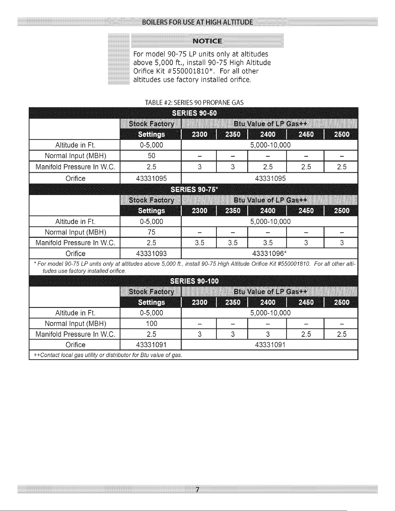
NOTICE
For
model
90-75
LP
units
only
at
altitudes
above
5,000
ft.,
install
90-75
High
Altitude
Orifice
Kit
#550001810*.
For
all
other
altitudes
use
factory
installed
orifice.
TABLE
#2:
SERIES
90
PROPANE
GAS
SERIES
90-50
eure
2300
|
2350
|
2400
Pye
Altitude
in
Ft.
0-5,000
5,000-10,000
Normal
Input
(MBH)
50
- - - - -
Manifold
Pressure
In
W.C.
2.9
3 3
2.9
2.5
2.9
Orifice
43331095 43331095
Ut)
ares
Settings
2300 2350 2400
2450
2500
Altitude
in
Ft.
0-5,000
5,000-10,000
Normal
Input
(MBH)
75
_ _ _ _ _
Manifold
Pressure
In
W.C.
2.9
3.9 3.9 3.9
3 3
Orifice
43331093
4333
1096*
*
For
model
90-75
LP
units
only
at
altitudes
above
5,000
ft,
install
90-75
High
Altitude
Orifice
Kit
#550001810.
For
all
other
aiti-
tudes
use
factory
installed
orifice.
SERIES
90-100
Settings
peje!)
2350 2400
2450 2500
Altitude
in
Ft.
0-5,000
5,000-10,000
Normal
Input
(MBH)
100
- - - - -
Manifold
Pressure
In
W.C.
2.9
3 3 3
2.5
2.9
Orifice
43331091 43331091
++Contact
local
gas
utility
or
distributor
for
Btu
value
of
gas.
RULES
FOR
SAFE
INSTALLATION
AND
OPERATION
1.
Read
the
entire
installation
manual
before
beginning
the
instal-
lation.
Failure
to
follow
these
rules
for
safe
installation
and
operation
and
these
instructions
could
cause
a
malfunction
of
the
boiler
and
result
in
death,
serious
bodily
injury,
and/or
property
damage.
2.
Check
all
applicable
state
and
local
building
codes and
util-
ity
company
requirements
before
installation.
The
installation
must
conform
with
these
requirements
in
their
entirety.
In
the
absence
of
these
codes,
use
NFPA
Installation
Codes
and
good
industry
practice.
3.
Before
servicing
the
boiler
-
allow
the
boiler
to
cool.
Always
shut
off
any
electricity
and
gas
supply
connected
to
the
boiler
prior
to
servicing.
Inspect
gas
line
for
leaks.
5.
Be
certain
gas
input
rate
is
correct.
Over
firing
may
result
in
early
failure
of
the
boiler
sections.
This
may
cause
dangerous
operation.
Under
firing
may
result
in
too
much
air
for
the
pre-
mix
burner
causing
poor
or
loss
of
combustion.
6.
Never
vent
the
products
of
combustion
from
this
boiler
to
an
enclosed
space.
Always
vent
to
the
outdoors.
Never
vent
to
another
room
or
to
inside
a
building.
7.
Be
sure
there
is
adequate
outdoor
air
supply
to
boiler
for
com-
plete
combustion.
8.
Follow
a
regular
service
and
maintenance
schedule
for
efficient
and
safe
operation.
9.
Keep
boiler
area
clean
of
debris
and
free
of
combustible
and
flammable
materials.
10.
Proper
through
the
wall
or
through
the
roof
combustion
vent-
ing
shall
be
in
accordance
with
the
materials and
methods
described
in
this
manual.
Installation
must
comply
with
local
codes.
11.
This
boiler
and
related
hot
water
heating
systems
are
not
do
it
yourself
items.
They
must
be
installed
and
serviced
by
qualified
professionals.
WARNING
This
boiler
has
been
equipped
for
residential
installations.
If
used
for
commercial
applications,
any
additional
code
requirements
must
be
adhered
to
for
installation.
This
may
require
additional
controls
including
but
not
limited
to
a
low
water
cut
off,
a
manual
reset
high
temperature
limit,
and
wiring
and/or
piping
modifications.
The
manufacturer
is
not
responsible
for
any
field
installation
changes
made
to
a
boiler
installation
which
are
not
described
or
acknowledged
in
this
manual.
BEFORE
INSTALLING
THE
BOILER
Complete
all
of
the
following
prior
to
installing
the
boiler.
Codes
This
boiler
product
is
a
gas-fired,
direct
vent,
condensing
boiler
and
must
be
installed
to
conform
to
the
requirements
of
the
authority
having
jursidiction
or,
in
the
absence
of
such
requirements:
United
States
-
National
Fuel
Gas
Code
(NFPA-54/ANSI
Z223.1).
Canada
-
National
Gas
and
Propane
Installation
Code,
Can/CSA
B149.1.
Where
required
by
the
authority
having
jurisdiction,
the
installation
must
conform
to
the
American
Society
of
Mechanical
Engineers
Safety
Code
for
Controls
and
Safety
Devices
for
Automatically
Fired
Boilers,
No.CSD-1.
NOTICE
Important
-
In
the
state
of
Massachusetts
this
product
must
be
installed
by
a
licensed
plumber
or
gas
fitter
and
the
installation
must
be
in
accordance
with
248
CMR.
Installers
-
Follow
local
regulations
with
respect
to
installation
of
CO
(Carbon
Monoxide)
Detectors.
Follow
maintenance
recommen-
dations
in
this
manual.
Installation
Requirements
Specific
To
The
State
Of
Massachusetts
For
Direct
Vent,
Mechanical
Vent,
And
Domestic
Hot
Water
Appliances
For
all
side
wall
horizontally
vented
gas
fueled
equipment
installed
in
every
dwelling,
building
or
structure
used
in
whole
or
in
part
for
residential
purposes,
including
those
owned
or
operated
by
the
commonwealth
and
where
the
side
wall
exhaust
vent
termination
is
less
than
seven
(7)
feet
above
finished
grade
in
the
area
of
the
vent-
ing,
including
but
not
limited
to
decks
and
porches,
the
following
requirements
shall
be
satisfied:
1.
Installation
of
carbon
monoxide
detectors:
at
the
time
of
instal-
lation
of
the
side
wall
horizontal
vented
gas
fueled
equipment,
the
installing
plumber
or
gasfitter
shall
observe
that
a
hard
wired
carbon
monoxide
detector
with
an
alarm
and
battery
back-up
is
installed
on
the
floor
level
where
the
gas
equipment
is
to
be
installed.
In
addition,
the
installing
plumber
or
gasfitter
shall
observe
that
a
battery
operated
or
hard
wired
carbon
mon-
oxide
detector
with
an
alarm
is
installed
on
each
additional
level
of
the
dwelling,
building
or
structure
served
by
the
side
wall
horizontal
vented
gas
fueled
equipment.
It
shall
be
the
respon-
sibility
of
the
property
owner
to
secure
the
services
of
qualified
licensed
professionals
for
the
installation
of
hard
wired
carbon
monoxide
detectors.
BEFORE
INSTALLING
THE
BOILER
A.
Inthe
event
that
the
side
wall
horizontally
vented
gas
Considerations
For
Boiler
Location
fueled
equipment
is
installed
in
a
crawl space
or
an
attic,
the
hard
wired
carbon
monoxide
detector
with
alarm
and
battery
back-up
may
be
installed
on
the
next
adjacent
floor
level.
B.
Inthe
event
that
the
requirements
of
this
subdivision
can
not
be
met
at
the
time
of
completion
of
installation,
the
owner
shall
have
a
period
of
thirty
(30)
days
to
comply
with
the
above
requirements;
provided,
however,
that
dur-
ing
said
thirty
(30)
day
period,
a
battery
operated
carbon
monoxide
detector
with
an
alarm
shall
be
installed.
2.
Approved
carbon
monoxide
detectors:
each
carbon
monoxide
detector
as
required
in
accordance
with
the
above
provisions
shall
comply
with
NFPA720
and
be
ANSI/UL
2034
listed
and
IAS
certified.
3.
Signage:
a
metal
or
plastic
identification
plate
shall
be
perma-
nently
mounted
to
the
exterior
of
the
building
at
a
minimum
height
of
eight
(8)
feet
above
grade
directly
in
line
with
the
exhaust
vent
terminal
for
the
horizontally
vented
gas
fueled
heating
appliance
or
equipment.
The
sign
shall
read,
in
print
size
no
less
than
one-half
(1/2)
inch
in
size,
“gas
vent
directly
below.
Keep
clear
of
all
obstructions”.
4.
Inspection:
the
state
or
local
gas
inspector
of
the
side
wall
horizontally
vented
gas
fueled
equipment
shall
not
approve
the
installation
unless,
upon
inspection,
the
inspector
observes
carbon
monoxide
detectors
and
signage
installed
in
accordance
with
the
provisions
of
248
CMR
5.08(2)(A)1
through
4.
5.
Product-approved
vent/air-intake:
a
product-approved
vent
ter-
minal
must
be
used
and,
if
applicable,
a
product-approved
air
1.
intake
must
be
used.
Installation
shall
be
in
strict
compliance
with
the
manufacturer’s
instructions.
6.
Installation
instructions:
a
copy
of
all
installation
instructions
2.
for
all
product
approved
side
wall
horizontally
vented
gas
fueled
equipment,
all
venting
instructions,
all
parts
lists
for
venting
instructions,
and/or
all
venting
design
instructions
shall
remain
with
the
appliance
or
equipment
at
the
completion
of
the
instal-
3,
lation.
Boiler
Sizing
Check
to
be
sure
you
have
selected
the
boiler
with
the
proper
capac-
ity
before
starting
the
installation.
The
I=B=R
Rating
of
the
boiler
selected
should
be
greater
than
or
equal
to
the
calculated
peak
heat-
ing
load
(heat
loss)
for
the
building
or
area(s)
served
by
the
boiler
and
associated
hot
water
heating
systems.
See
the
table
“BOTLER
RATINGS
AND
CAPACITIES”
(page
5
of
this
document).
Heat
loss
calculations
should
be
based
on
approved
industry
meth-
ods.
Before
selecting
a
location
for
the
boiler,
the
following
should
be
considered.
Each
boiler
considered.
¢Supplied
with
the
correct
type
of
gas
(natural
gas
or
pro-
pane).
«Connected
to
a
suitable
combustion
air
intake
piping
sys-
tem
to
supply
the
correct
amounts
of
fresh
(outdoor)
air
for
combustion,
refer
to
Combustion
Air
And
Vent
Pipe
section
(near
center
of
this
manual)
for
details.
«Connected
to
a
suitable
venting
system
to
remove
the
hazardous
products
of
gas
combustion,
refer
to
Combus-
tion
Air
And
Vent
Pipe
section
(page
19
of
this
manual)
for
details,
*Connected
to
a
suitable
hot
water
heating
system.
¢Supplied
with
a
suitable
electrical
supply
for
all
boiler
mo-
tors
and
controls.
«Connected
to
a
properly
located
thermostat
or
operating
control,
(not
included
with
boiler)
«Placed
on
level
surface
(must
NOT
be
installed
on
carpet-
ing)
«Condensate
drain
line
must
be
pitched
down
to
floor
drain
or
external
condensate
pump
with
reservoir
at
4”
per foot
(wood
frame
or
blocks
may
be
used
to
raise
boiler).
Locating
The
Boiler
Select
a
location
which
is
level,
central
to
the
piping
systems
served
and
as
close
to
the
vent
and
air
intake
terminals
as
pos-
sible.
Accessibility
clearances,
if
more
stringent
(i.e.
larger
clearances)
than
required
fire
protection
clearances,
must
be
used
for
the
boiler
installation.
Accessibility
clearances
may
be
achieved
with
the
use
of
removable
walls
or
partitions.
The
boiler
is
approved
for
installation
in
closets
and
on
com-
bustible
floors.
This
boiler
shall
NOT
be
installed
on
carpeting.
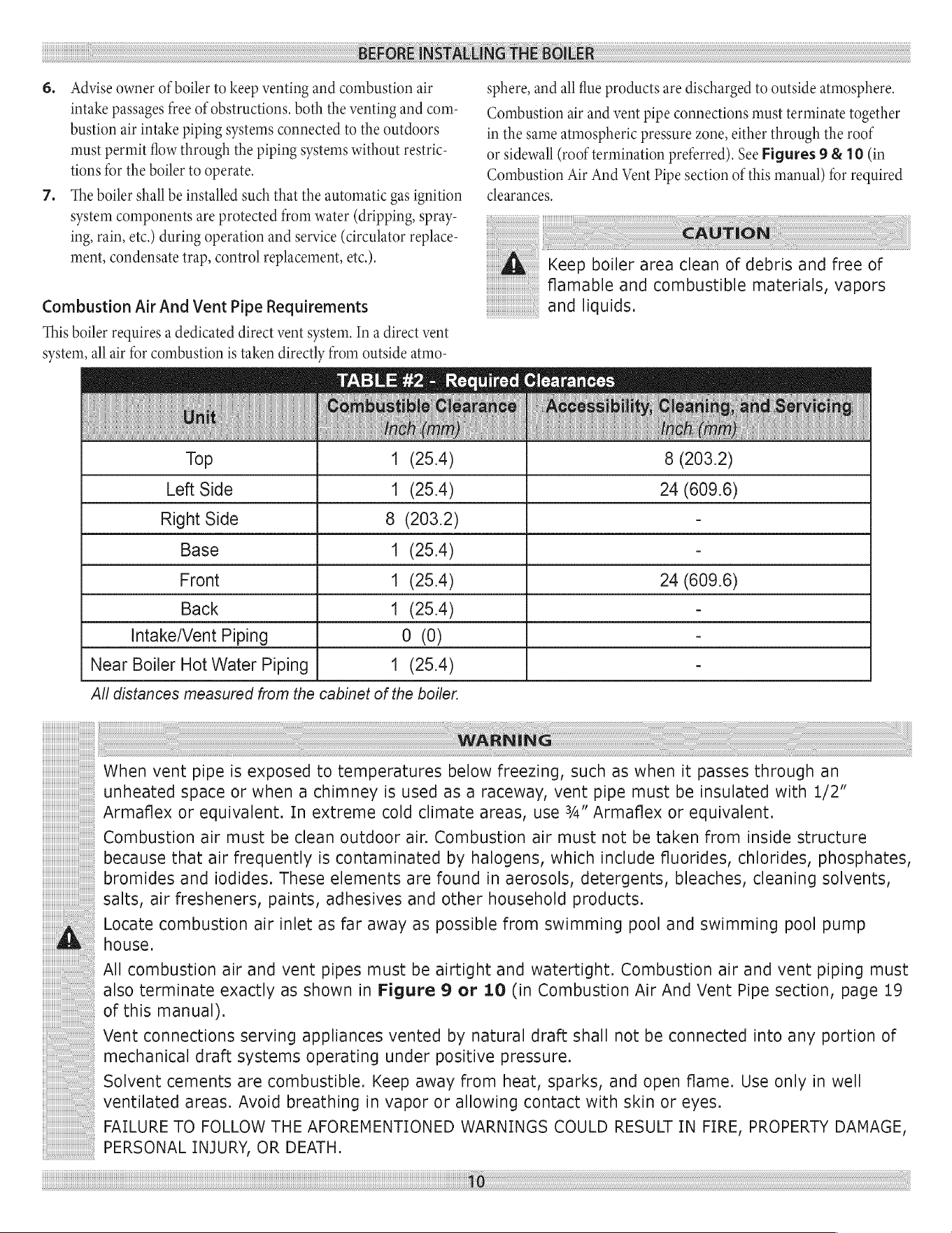
The
clearances
shown
in
Table
#2
indicate
required
clearances.
A
minimum
1”
clearance
must
be
maintained
between
com-
bustible
construction
and
each
of
the
left,
top
and
back
surfaces
of
the
boiler.
A
minimum
8”
clearance
is
required
on
the
right
side,
to
allow
room
for
the
inlet
air
pipe.
An
18”
clearance
must
be
maintained
at
a
side
where
passage
is
required
to
access
an-
other
side
for
cleaning
or
servicing,
inspection
or
replacement
of
any
parts
that
normally
may
require
such
attention.
Allow
at
least
24”
at
the
front
and
left
side
and
8”
at
the
top
for
servicing.
No
clearances
are
required
to
venting
or
combustion
air
intake
piping.
Equipment
shall
be
installed
in
a
location
which
facilitates
the
operation
of
venting
and
combustion
air
intake
piping
systems
as
described
in
this
manual.
BEFORE
INSTALLING
THE
BOILER
6.
Advise
owner
of
boiler
to
keep
venting
and
combustion
air
intake
passages
free of
obstructions.
both
the
venting
and
com-
bustion
air
intake
piping
systems
connected
to
the
outdoors
must
permit
flow
through
the
piping
systems
without
restric-
tions
for
the
boiler
to
operate.
7.
The
boiler
shall
be
installed
such
that
the
automatic
gas
ignition
system
components
are
protected
from
water
(dripping,
spray-
ing,
rain,
etc.)
during
operation
and
service
(circulator
replace-
ment,
condensate
trap,
control
replacement,
etc.).
Combustion
Air
And
Vent
Pipe
Requirements
This
boiler
requires
a
dedicated
direct
vent
system.
In
a
direct
vent
system,
all
air
for
combustion
is
taken
directly
from
outside
atmo-
Top
sphere,
and
all
flue
products
are
discharged
to
outside
atmosphere.
Combustion
air
and
vent
pipe
connections
must
terminate
together
in
the
same
atmospheric
pressure
zone,
either
through
the
roof
or
sidewall
(roof
termination
preferred).
See
Figures
9
& 10
(in
Combustion
Air
And
Vent
Pipe
section
of
this
manual)
for
required
clearances.
CAUTION
A
Keep
boiler
area
clean
of
debris
and
free
of
flamable
and
combustible
materials,
vapors
and
liquids.
TABLE
#2
-
Required
Clearances
8
(203.2)
1
(25.4)
Left
Side
1
(25.4)
24
(609.6)
Right
Side
8
(203.2)
-
Base
1
(25.4)
-
Front
1
(25.4)
24
(609.6)
Back
1
(25.4)
-
Intake/Vent
Piping
0
(0)
-
Near
Boiler
Hot
Water
Piping
1
(25.4)
-
All
distances
measured
from
the
cabinet
of
the
boiler.
WARNING
When
vent
pipe
is
exposed
to
temperatures
below
freezing,
such
as
when
it
passes
through
an
unheated
space
or
when
a
chimney
is
used
as
a
raceway,
vent
pipe
must
be
insulated
with
1/2”
Armaflex
or
equivalent.
In
extreme
cold
climate
areas,
use
34”
Armaflex
or
equivalent.
Combustion
air
must
be
clean
outdoor
air.
Combustion
air
must
not
be
taken
from
inside
structure
because
that
air
frequently
is
contaminated
by
halogens,
which
include
fluorides,
chlorides,
phosphates,
bromides
and
iodides.
These
elements
are
found
in
aerosols,
detergents,
bleaches,
cleaning
solvents,
salts,
air
fresheners,
paints,
adhesives
and
other
household
products.
A
Locate
combustion
air
inlet
as
far
away
as
possible
from
swimming
pool
and
swimming
pool
pump
house.
All
combustion
air
and
vent
pipes
must
be
airtight
and
watertight.
Combustion
air
and
vent
piping
must
also
terminate
exactly
as
shown
in
Figure
9
or
10
(in
Combustion
Air
And
Vent
Pipe
section,
page
19
of
this
manual).
Vent
connections
serving
appliances
vented
by
natural
draft
shall
not
be
connected
into
any
portion
of
mechanical
draft
systems
operating
under
positive
pressure.
Solvent
cements
are
combustible.
Keep
away
from
heat,
sparks,
and
open
flame.
Use
only
in
well
ventilated
areas.
Avoid
breathing
in
vapor
or
allowing
contact
with
skin
or
eyes.
FAILURE
TO
FOLLOW
THE
AFOREMENTIONED
WARNINGS
COULD
RESULT
IN
FIRE,
PROPERTY
DAMAGE,
PERSONAL
INJURY,
OR
DEATH.
10
BEFORE
INSTALLING
THE
BOILER
Condensate
Drain
Requirements
Condensate
drain
line
to
be
pitched
down
to
floor
drain
at
a
mini-
mum
of
4”
per
foot.
An
external
condensate
pump
(not
furnished)
may
be
used
if
floor
drain
is
not
available.
The
condensate
pump
must
be
designed
for
flue
gas
condensate
application.
NOTICE
1.
Condensate
trap
is
built
into
the
boiler,
an
external
trap
is
not
required
and
should
not
be
used.
2.
Wood
frame
or
blocks
may
be
used
to
raise
the
boiler
to
maintain
drain
pitch
or
to
be
above
external
condensate
pump
reservoir.
3.
There
is
a
115
Volt
AC
receptacle
provided
on
the
service
switch
junction
box
which
is
located
at
the
boiler
right
side,
to
provide
power
for
an
external
condensate
pump
(if
needed).
Foundation
Requirements
Boiler
must
be
placed
on
level
surface.
Boiler
is
NOT
to
be
installed
on
carpeting.
NOTICE
If
boiler
is
not
level
condensate
drain
lines
will
not
function
properly.
Adjustable
feet
are
located
on
the
boiler
to
make
up
for
minor
surface
irregularities
or
tilt.
Wood
frame
or
blocks
may
be
used
to
raise
boiler
to
maintain
drain
pitch
or
to
be
above
external
condensate
pump
reservoir.
Removal
of
Existing
Boiler
From
Common
Vent
System
When
an
existing
boiler
is
removed
from
a
common
venting
system,
the
common
venting
system
is
likely
to
be
too
large
for
proper
vent-
ing
of
the
appliances
remaining
connected
to
it.
At
the
time
of
re-
moval
of
an
existing
boiler,
the
following
steps
shall
be
followed
with
each
appliance
remaining
connected
to
the
common
venting
system
placed
in
operation,
while
the
other
appliances
remaining
connected
to
the
common
venting
system
are
not
in
operation.
1.
Seal
any
unused
openings
in
the
common
venting
system.
2.
Visually
inspect
the
venting
system
for
proper
size
and
hori-
zontal
pitch
and
determine
there
is
no
blockage,
or
restrictions,
leakage,
corrosion
and
other
deficiencies
which
could
cause
an
unsafe
condition.
3.
In-so-far
as
is
practical,
close
all
building
doors
and
windows
and
all
doors
between
the
space
in
which
the
appliances
remain-
ing
connected
to
the
common
venting
system
are
located
and
other
spaces
of
the
building.
Turn
on
clothes
dryer
and any
ap-
pliance
not
connected
to
the
common
venting
system.
Turn
on
any
exhaust
fans,
such
as
range
hoods
and
bathroom
exhaust,
so
they
will
operate
at
maximum
speed.
Do
not
operate
a
summer
exhaust
fan.
Close
fire
dampers.
4.
Place
in
operation
the
appliance
being
inspected.
Follow
the
lighting
instructions.
Adjust
thermostat
so
appliances
will
oper-
ate
continuously.
5.
Test
for
spillage
at
the
draft
hood
relief
opening
after
5
minutes
of
main
burner
operation.
Use
the
flame
of
a
match
or
candle,
or
the
smoke
from
a
cigarette,
cigar
or
pipe.
6.
After
it
has
been
determined
that
each
appliance
remaining
connected
to
the
common
venting
system
properly
vents
when
tested
as
outlined
above, return
doors,
windows,
exhaust
fans,
fire
place
dampers,
and
any
other
gas-burning
appliance
to
their
previous
condition
of use.
7.
Any
improper
operation
of
the
common
venting
system
should
be
corrected
so
the
installation
conforms
with
the
National
Fuel
Code,
NFPA-54/ANSI
-Z223.1
and/or
the
Natural
Gas and
Propane
Installation
Code,
CAN/CSA
B149.1..
When
resizing
any
portion
of
the
common
venting
system,
the
common
vent-
ing
system
should
be
resized
to
approach
the
minimum
size
as
determined
using
the
appropriate
tables
in
Chapter
13
of
the
National
Fuel
Gas
Code,
NFPA-54/ANSI-
Z223.1
and/or
the
Natural
Gas and
Propane
Installation
Code,
CAN/CSA
B149.1.
PLACING
THE
BOILER
The
boiler
should
be
placed
to
provide
the
most
direct
connections
to
the
combustion
air,
vent
and
system
piping
as
possible.
Place
crated
boiler
as
close
to
selected
location
as
possible
and
uncrate
boiler.
The
uncrated
boiler
may
be
moved
into
position
with
an
appliance
dolly
or
2-wheel
hand
truck.
The
dolly
or
hand
truck
should
be
inserted
under
the
left
hand
side
of
the boiler.
It
is
possible
to
slide
the
boiler
for
a
short
distance
on
a
smooth
floor
or
surface.
1
NOTICE
Refer
to
manual
section
“locating
the
boiler”
(page
9
of
this
manual),
for
required
clearances
for
servicing
and
maintenance.
NEAR
BOILER
PIPING
When
the
installation
of
the
boiler
is
for
a
new
heating
system,
first
install
all
of
the
radiation
units
(panels,
radiators,
baseboard,
or
tub-
ing)
and
the
supply
and
return
mains.
After
all
heating
system
piping
and
components
have
been
installed,
make
final
connection
of
the
system
piping
to
the
boiler.
A
hot
water
boiler
installed
above
radia-
tion
level,
or
as
required
by
the
Authority
having
jurisdiction,
must
be
equipped
with
a
low
water
cut
off
device.
A
periodic
inspection
is
necessary
for
flushing
of float
type
devices,
per
low
water
cut
off
manufacturers
specific
instructions.
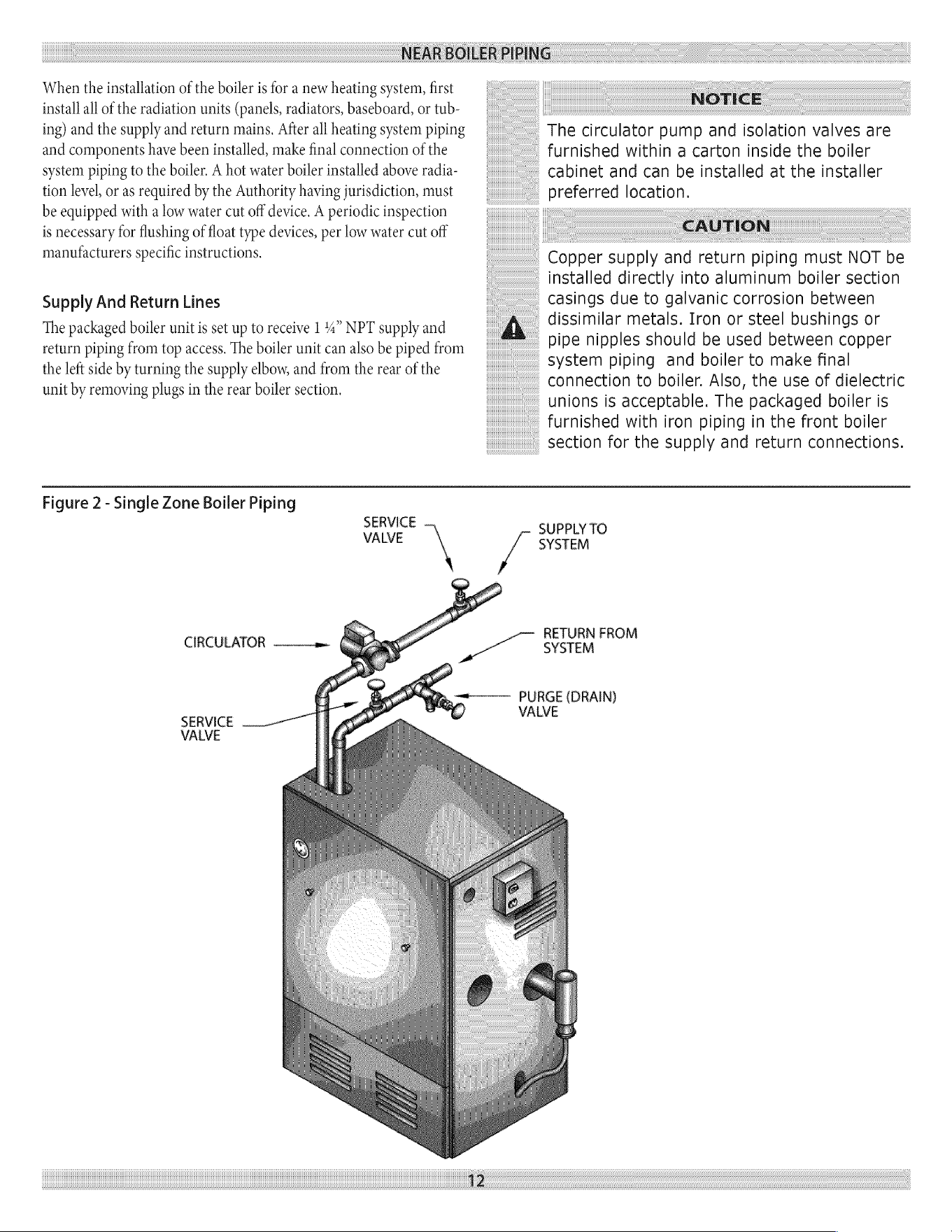
Supply
And
Return
Lines
The
packaged
boiler
unit
is
set
up
to
receive
1
4”
NPT
supply
and
return
piping
from
top
access.
The
boiler
unit
can
also
be
piped
from
the
left
side
by
turning
the
supply
elbow,
and
from
the
rear
of
the
unit
by
removing
plugs
in
the
rear
boiler
section.
NOTICE
The
circulator
pump
and
isolation
valves
are
furnished
within
a
carton
inside
the
boiler
cabinet
and
can
be
installed
at
the
installer
preferred
location.
CAUTION
Copper
supply
and
return
piping
must
NOT
be
installed
directly
into
aluminum
boiler
section
casings
due
to
galvanic
corrosion
between
dissimilar
metals.
Iron
or
steel
bushings
or
pipe
nipples
should
be
used
between
copper
system
piping
and
boiler
to
make
final
connection
to
boiler.
Also, the
use
of
dielectric
unions
is
acceptable.
The
packaged
boiler
is
furnished
with
iron
piping
in
the
front
boiler
section
for
the
supply
and
return
connections.
Figure
2
-
Single
Zone
Boiler
Piping
SERVICE
VALVE
\
CIRCULATOR
————a-
SUPPLY
TO
J
SYSTEM
RETURN
FROM
SYSTEM
By
tee
PURGE
(DRAIN)
SERVICE
VALVE
12
NEAR
BOILER
PIPING
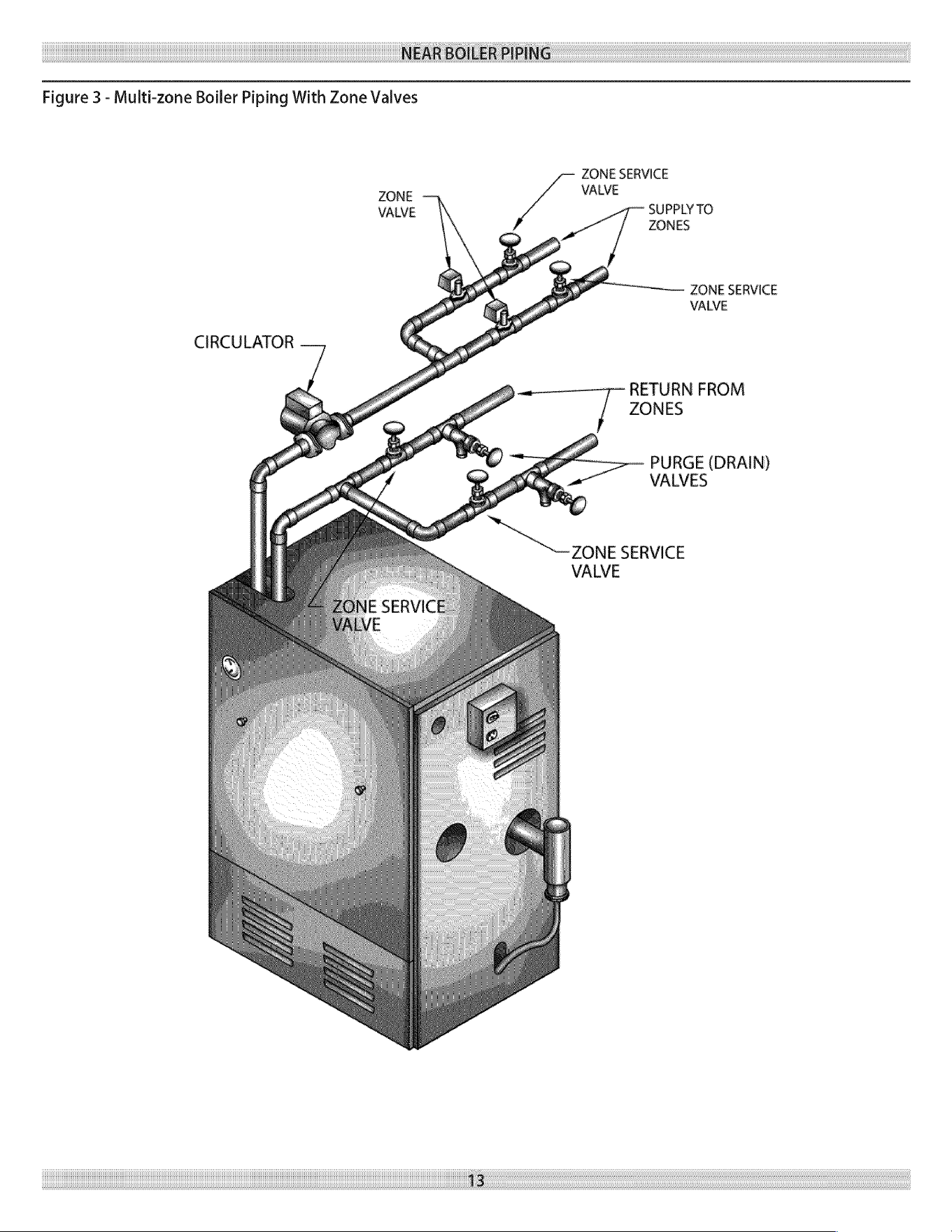
Figure
3
-
Multi-zone
Boiler
Piping
With
Zone
Valves
ZONE
SERVICE
ZONE
VALVE
VALVE
SUPPLY
TO
ZONES
ZONE
SERVICE
VALVE
CIRCULATOR
RETURN
FROM
ZONES
PURGE
(DRAIN)
VALVES
ZONE
SERVICE
VALVE
13:
NEAR
BOILER
PIPING
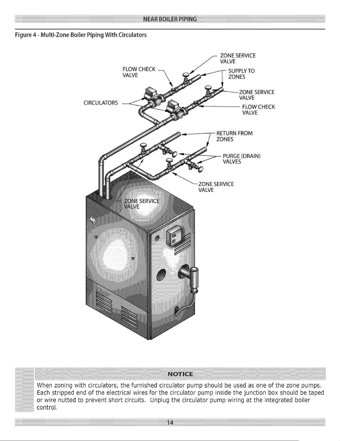
Figure
4
-
Multi-Zone
Boiler
Piping
With
Circulators
ZONE
SERVICE
VALVE
SUPPLY
TO
ZONES
FLOW
CHECK
VALVE
ZONE
SERVICE
Oval
VALVE
tremens
EL
OW
CHECK
VALVE
——
RETURN
FROM
~
ZONES
PURGE
(DRAIN)
VALVES
None
SERVICE
VALVE
CIRCULATORS
<
J
NOTICE
When
zoning
with
circulators,
the
furnished
circulator
pump
should
be
used
as
one
of
the
zone
pumps.
Each stripped
end
of
the
electrical
wires
for
the
circulator
pump
inside
the
junction
box
should
be
taped
or
wire
nutted
to
prevent
short
circuits.
Unplug
the
circulator
pump
wiring
at
the
integrated
boiler
control.
14
NEAR
BOILER
PIPING
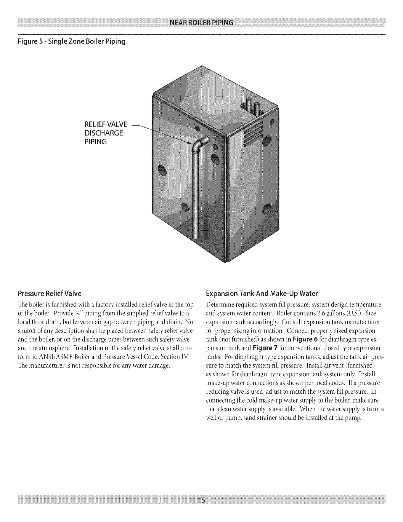
Figure
5
-
Single
Zone
Boiler
Piping
RELIEF
VALVE
DISCHARGE
PIPING
Pressure
Relief
Valve
The
boiler
is
furnished
with
a
factory
installed
relief
valve
in
the
top
of
the
boiler.
Provide
%4”
piping
from
the
supplied
relief
valve
to
a
local
floor
drain,
but
leave
an
air
gap
between
piping
and
drain.
No
shutoff
of
any
description
shall
be
placed
between
safety
relief
valve
and
the
boiler,
or
on
the
discharge
pipes
between
such
safety
valve
and
the
atmosphere.
Installation
of
the
safety
relief
valve
shall
con-
form
to
ANSI/ASME
Boiler
and
Pressure
Vessel
Code,
Section
IV.
The
manufacturer
is
not
responsible
for
any
water
damage.
15
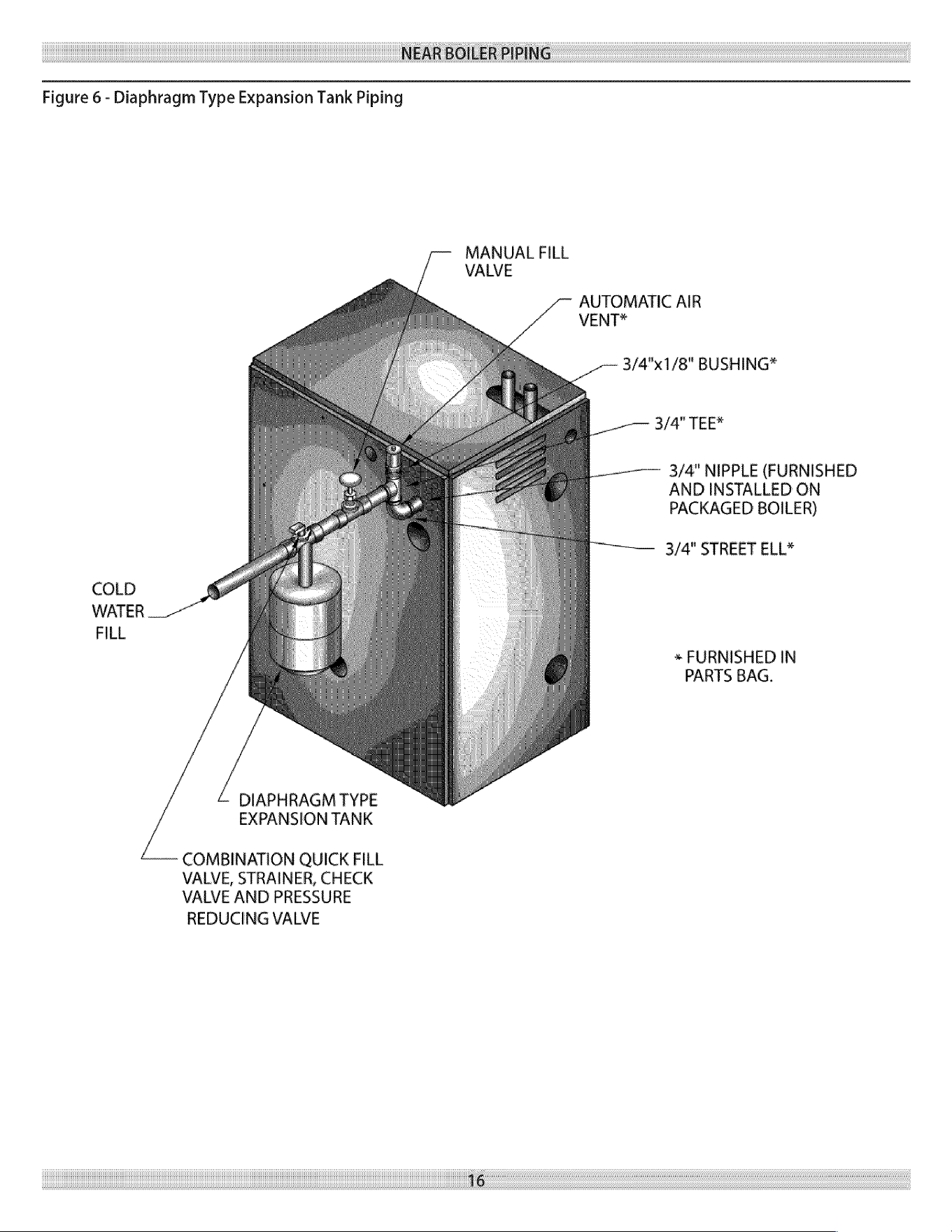
Expansion
Tank
And
Make-Up
Water
Determine
required
system
fill
pressure,
system
design
temperature,
and
system
water
content.
Boiler
contains
2.6
gallons
(U.S.).
Size
expansion
tank
accordingly.
Consult
expansion
tank
manufacturer
for
proper
sizing
information.
Connect
properly
sized
expansion
tank
(not
furnished)
as
shown
in
Figure
6
for
diaphragm
type
ex-
pansion
tank
and
Figure
7
for
conventional
closed
type
expansion
tanks.
For
diaphragm
type
expansion
tanks, adjust
the
tank
air
pres-
sure
to
match
the
system
fill
pressure.
Install
air
vent
(furnished)
as
shown
for
diaphragm
type
expansion
tank
system
only.
Install
make-up
water
connections
as
shown
per
local
codes.
Ifa
pressure
reducing
valve
is
used,
adjust
to
match
the
system
fill
pressure.
In
connecting
the
cold
make-up
water
supply
to
the
boiler,
make
sure
that
clean
water
supply
is
available.
When
the
water
supply
is
from
a
well
or
pump,
sand
strainer
should
be
installed
at
the
pump.
NEAR
BOILER
PIPING
Figure
6
-
Diaphragm
Type
Expansion
Tank
Piping
MANUAL
FILL
VALVE
AUTOMATIC
AIR
VENT*
3/4"x1/8"
BUSHING*
3/4"
TEE*
3/4"
NIPPLE
(FURNISHED
AND
INSTALLED
ON
PACKAGED
BOILER)
3/4"
STREET
ELL*
COLD
WATER
FILL
»
FURNISHED
IN
PARTS
BAG.
DIAPHRAGM
TYPE
EXPANSION
TANK
COMBINATION
QUICK
FILL
VALVE,
STRAINER,
CHECK
VALVE
AND
PRESSURE
REDUCING
VALVE
16
NEAR
BOILER
PIPING
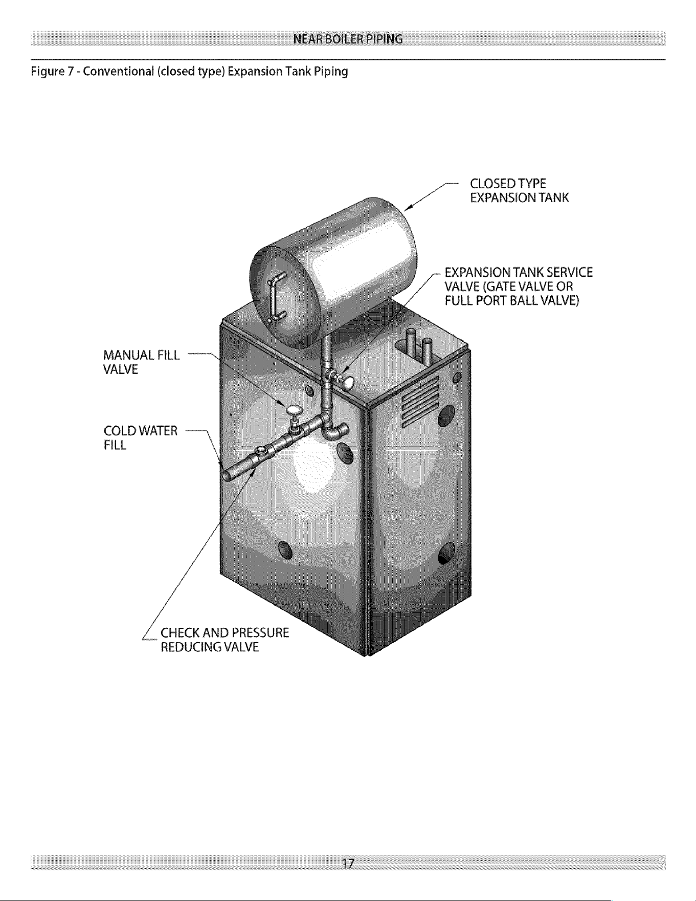
Figure
7
-
Conventional
(closed
type)
Expansion
Tank
Piping
CLOSED
TYPE
EXPANSION
TANK
EXPANSION
TANK
SERVICE
VALVE
(GATE
VALVE
OR
FULL
PORT
BALL
VALVE)
MANUAL
FILL
VALVE
COLD
WATER
FILL
CHECK AND
PRESSURE
REDUCING
VALVE
7
NEAR
BOILER
PIPING
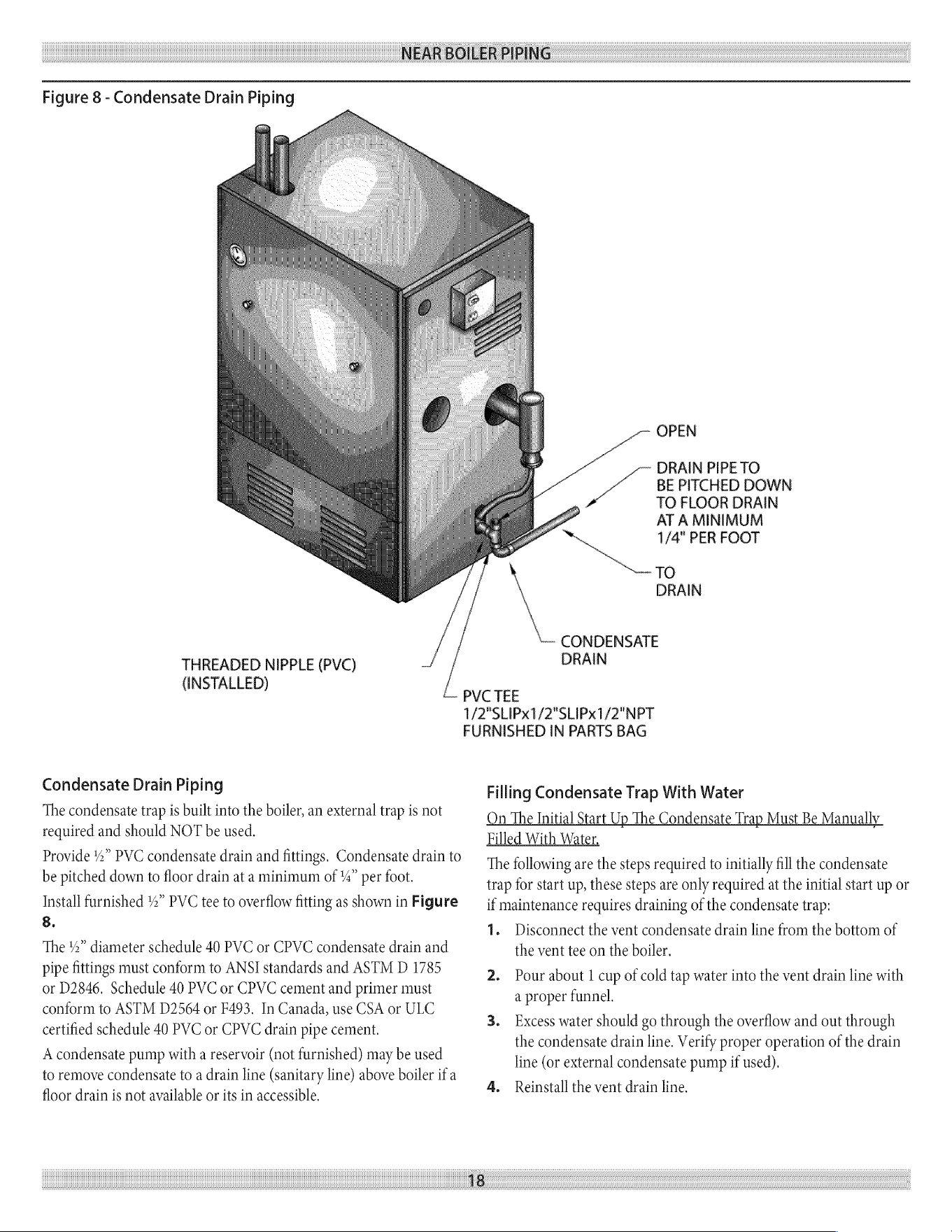
Figure
8
-
Condensate
Drain
Piping
THREADED
NIPPLE
(PVC)
(INSTALLED)
Condensate
Drain
Piping
The
condensate
trap
is
built
into
the
boiler,
an
external
trap
is
not
required
and
should
NOT
be
used.
Provide
4%”
PVC
condensate
drain
and
fittings.
Condensate
drain
to
be
pitched
down
to
floor
drain
at
a
minimum
of
4”
per
foot.
Install
furnished
%”
PVC
tee
to
overflow
fitting
as
shown
in
Figure
8.
The
2”
diameter
schedule
40
PVC
or
CPVC
condensate
drain
and
pipe
fittings
must
conform
to
ANSI
standards
and
ASTM
D
1785
or
D2846.
Schedule
40
PVC
or
CPVC
cement
and
primer
must
conform
to
ASTM
D2564
or
F493.
In
Canada,
use
CSA
or
ULC
certified
schedule
40
PVC
or
CPVC
drain
pipe
cement.
A
condensate
pump
with
a
reservoir
(not
furnished)
may
be
used
to
remove
condensate
to
a
drain
line
(sanitary
line)
above
boiler
if
a
floor
drain
is
not
available
or
its
in
accessible.
OPEN
DRAIN
PIPE
TO
BE
PITCHED
DOWN
TO
FLOOR
DRAIN
AT
A
MINIMUM
1/4"
PER
FOOT
TO
DRAIN
CONDENSATE
DRAIN
PVC
TEE
1/2"SLIPX1/2"SLIPX1/2"NPT
FURNISHED
IN
PARTS
BAG
Filling
Condensate
Trap
With
Water
Qn
The
Initial
Start
Up
The
Condensate
Trap
Must
Be
Manuall
Filled
With
Water,
The
following
are
the
steps
required
to
initially
fill
the
condensate
trap
for
start
up,
these
steps
are
only
required
at
the
initial
start
up
or
if
maintenance
requires
draining
of
the
condensate
trap:
1.
Disconnect
the
vent
condensate
drain
line
from
the
bottom
of
the
vent
tee
on
the
boiler.
2.
Pour
about
1
cup
of
cold
tap
water
into
the
vent
drain
line
with
a
proper
funnel.
3.
Excess
water
should
go
through
the
overflow
and
out
through
the
condensate
drain
line.
Verify
proper
operation
of
the
drain
line
(or
external
condensate
pump
if
used).
4.
Reinstall
the
vent
drain
line.
NEAR
BOILER
PIPING
Chilled
Water
Piping
The
boiler,
when
used
in
connection
with
a
refrigeration
system,
must
be
installed
so
the
chiller
medium
is
piped
in
parallel
with
the
boiler
with
appropriate
valves
to
prevent
the
chilled
medium
from
entering
the boiler.
The
boiler
piping
system
of
a
hot
water
boiler
connected
to
heat-
ing
coils
is
located
in
air
handling
units
where
they
may
be
exposed
to
refrigerated
air
circulation
must
be
equipped
with
flow
control
valves
or
other
automatic
means
to
prevent
gravity
circulation
of
the
boiler
water
during
cooling
cycle.
COMBUSTION
AIR
AND
VENT
PIPE
Connections
And
Termination
Provisions
for
combustion
and
ventilation
air
must
be
in
accordance
with
section,
Air
For
Combustion
and
Ventilation,
of
the
National
Fuel
Gas
Code,
ANSI
2223.1/NFPA54,
or
Sections
8.2, 8.3
or
8.4
of
National
Gas
and
Propane
Installation
Code,
CAN/CGA-B
149.1,
or
applicable
provisions
of
the
local
building
code.
These
boilers
require
a
dedicated
direct
vent
system.
All
air
for
com-
bustion
is
taken
directly
from
outdoors
through
the
combustion
air
intake
pipe.
All
flue
products
are
discharged
to
the
outdoors
through
the
vent
pipe.
1.
Refer
to
Combustion
Air
And
Vent
Pipe
section
that
follows,
also
see
Figures
9
&
10
for
combustion
air
and
vent
pipe
roof
and
sidewall
termination.
(Roof
termination
is
preferred)
Combustion
air
and
vent
pipes
must
terminate
together
in
same
atmo
spheric
pressure
zone
as
shown.
Construction
through
which
vent
and
air
intake
pipes
may
be
installed
is
a
maximum
24
inches,
minimum
'4”
thickness.
2.
Combustion
air
and
vent
pipe
fittings
must
conform
to
American
National
Standards
Institute
(ANSI)
standards
and
American
Society
for
Testing
and
Materials
(ASTM)
standards
D1784
(schedule-40
CPVC),
D1785
(schedule-40
PVC),
D2665
(PVC-DWYV),
D2241
(SDR-21
and
SDR-26
PVC),
D2661
(ABS-
DWV),
or
F628
(schedule-40
ABS),
Pipe
cement
and
primer
must
conform
to
ASTM
standards
D2564
(PVC)
or
D2235
(ABS).
In
Canada
construct
all
combustion
air
and
vent pipes
for
this
unit
of
CSA
or
ULC
certified
schedule-40
CPVC,
schedule-40
PVC,
PVC-DWV
or
ABS-DWYV
pipe
and
pipe
cement.
SDR
pipe
is
NOT
approved
in
Canada.
3.
Combustion
air
and
vent
piping
connections
on
boiler
are
sized
for
2”
pipe.
Any
pipe
size
change
(to
3”)
must
be
made
outside
of
the
boiler
casing
in
a
vertical
run
of
pipe
to
allow
for
proper
drainage
of
vent
condensate.
Due
to
potential
for
flue
gas
tem-
peratures
over
155°F,
the
first
five
(5)
feet
of
vent
pipe
must
be
CPVC,
the
remaining
vent
pipe
can
be
PVC.
If
any
elbows
are
employed
within
the
first
5
feet
of
vent,
they
must
be
CPVC
too.
Two
(2)
-
30”
pieces
of
2”
CPVC
pipe
are
furnished
with
the
boiler.
NOTICE
The
transition
from
2”
pipe
to
3”
pipe
must
be
made
in
a
vertical
run.
HoT
|
arti
|
Standard
ASTM
F891
*
ASTM
D2665
**
ASTM
D1785
**
ASTM
D2241
**
158
|
70
- -
ASTM
D2846
**
ASTM
F441
*
ASTM
F442
*
210
|
100
|
— -
ASTM
D2661
***
180
|
82
7 7
ASTM
F628
***
UL-1738
414
ULC
S636
212
|
— -
*
Allowable
temperatures
based
on
Classifications
covered
in
ASTM
D4396
[Deflection
Temperatures
under
Load
(264
psi)
(1819KPa)].
*™
Allowable
temperatures
based
on
Classifications
covered
in
ASTM
D1784
[Deflection
Temperatures
under
Load
(264
psi)
(1819KPa)].
***
Allowable
temperatures
based
on
Classifications
covered
in
ASTM
D3965
[Deflection
Temperatures
under
Load
(264
psi)
(1819KPa)].
12
COMBUSTION
AIR
AND
VENT
PIPE
4.
Combustion
air
and
vent
piping
lengths:
BOILER
2
PIPE
MINIMUM
2
PIPE
MAXIMUM
|
3°
PIPE
MINIMUM
3
PIPE
MAXIMUM
SIZE
VENTING VENTING
VENTING
VENTING
cee
2
FEET
21
FEET
15
FEET
92
FEET
75
&
50
2
FEET
26
FEET
20
FEET
112
FEET
The
first
5
ft.
of
“TOTAL
EQUIVALENT
LENGTH”
of
vent
piping
¢
Termination
should
be
positioned
where
it
will
not
be
run
must
be
2”
CPVC:
subjected
to
potential
damage
by
foreign
objects,
such
as
The
length
of
pipe
is
counted
from
the
boiler
jacket
(air
intake
pipe)
stones,
balls,
etc..
or
from
vent
tee
(vent pipe)
the
termination
is
not
counted
toward
+
Termination
should
be
positioned
where
vent
vapors
are
not
the
“Total
Equivalent
Length”.
objectionable.
For
additional
elbows,
reduce
the
maximum
vent
length
as
shown:
»
Put
vent
on
a
wall
away
from
the
prevailing
winter
wind.
*
2°
90°
elbow
-1
'
ft.
per
additional
elbow.
Locate
or
guard
the
vent
to
prevent
accidental
contact
with
+
3”
90°
elbow
-
3 ft.
per
additional
elbow.
people
or
pets.
Terminate
the
vent
above
normal
snowline.
Avoid
locations
Example:
where
snow
may
drift
and block
the
vent.
Ice
or
snow
may
cause
the
boiler
to
shut
down
if
the
vent
becomes
obstructed.
To
add
2
additional
90
*
elbows
to
a
3°
pipe
for
a
75
boiler,
Under
certain
conditions,
flue
gas
will
condense,
forming
Fach
elbow
is
3
additional
ft.
per
90
°
elbow
for
a
total
of
6
ft..
moisture,
and
may
be
corrosive.
In
such
cases,
steps
should
be
taken
to
prevent
building
materials
at
the
vent
from
being
damaged
by
exhaust
of
flue gas.
(1
elbow
@
3
ft.
+
|
elbow
@ 3
ft.
=
6
additional
ft.
of
pipe)
Vent
shall
not
terminate
where
it
may
cause
hazardous
frost
or
ice
accumulations
on
adjacent
property
surfaces.
‘The
total
additional
pipe
is
then
subtracted
from
the
maximum
props’
allowable
pipe
length
to
give
the
new
maximum
length
of
94
ft.
7.
The
venting
system
shall
terminate
at
least
3 ft.
(0.9m)
above
with
6,
90°
elbows.
any
forced
air
inlet
(except
the
boiler’s
combustion
air
inlet)
(“TOTAL
EQUIVALENT
LENGTH’).
within
10
ft.(3m).
The
venting
system
shall
terminate
at
least
12
_
_
in.
from
any
air
opening
into
any
building.
The
bottom
of
the
Original
100
ft.
max,
-
6
ft,
for
2
additional
elbows
=
new
9
ft.
vent
shall
be
located
at
least
12
in.
above
grade.
Termination
maximum
length.
of
the
vent
shall
be
not
less
than
7
ft.
(2.1m)
above
an
adjacent
public
walkway
or
paved
driveway.
The
vent
terminal
shall
not
be
installed
closer
than
3 ft.
from
the
inside
corner
of
an
L
shaped
structure.
Termination
of
the
vent
should
be
kept
at
least
3 ft.
away
from
vegetation.
USA
only,
The
venting
system
shall
terminate
at
least
4
ft.
horizontally
from,
and
in
no
case
above
or
below,
unless
a
4
ft.
(1.22m)
horizontal
distance
is
maintained,
from
elec-
tric
meters,
gas
meters,
regulators,
and
relief
equipment.
Canada
only,
The
venting
system
shall
terminate
at
least
6
ft.
(1.83m)
horizontally
from,
an
in
no
case
above
or
below,
unless
a
6
ft.
(1.83m)
horizontal
distance
is
maintained,
from
electric
meters,
gas
meters,
regulators,
and
relief
equipment.
5.
Combustion
air
and
vent
piping
to
be
pitched
back
to
boiler
at
minimum
'4”
per
ft.
(21
mm/m)
from
intake
and
vent
terminals
so
that
all
moisture
in
combustion
air
and
vent
piping
drains
to
boiler.
Pipes
must
be
pitched
continuously
with
no
sags
or
low
spots
where
moisture
can
accumulate
and block
the
flow
of
air
or
flue gas.
Combustion
air
and
vent
pipes
must
be
airtight
and
watertight.
6.
Consideration
for
the
following
should
be
used
when
determining
an
appropriate
location
for
termination
of
combustion
air
and
vent
piping.
¢
Comply
with
all
clearances
required
as
stated
in
paragraph
7.
e
Termination
should
be
positioned
where
vent
vapors
will
not
damage
plants/shrubs
or
air
conditioning
equipment.
¢
Termination
should
be
positioned
so
that
it
will
not
be
effected
by
wind
eddy,
air
born
leaves,
snow,
or
recirculated
flue
gases.
20
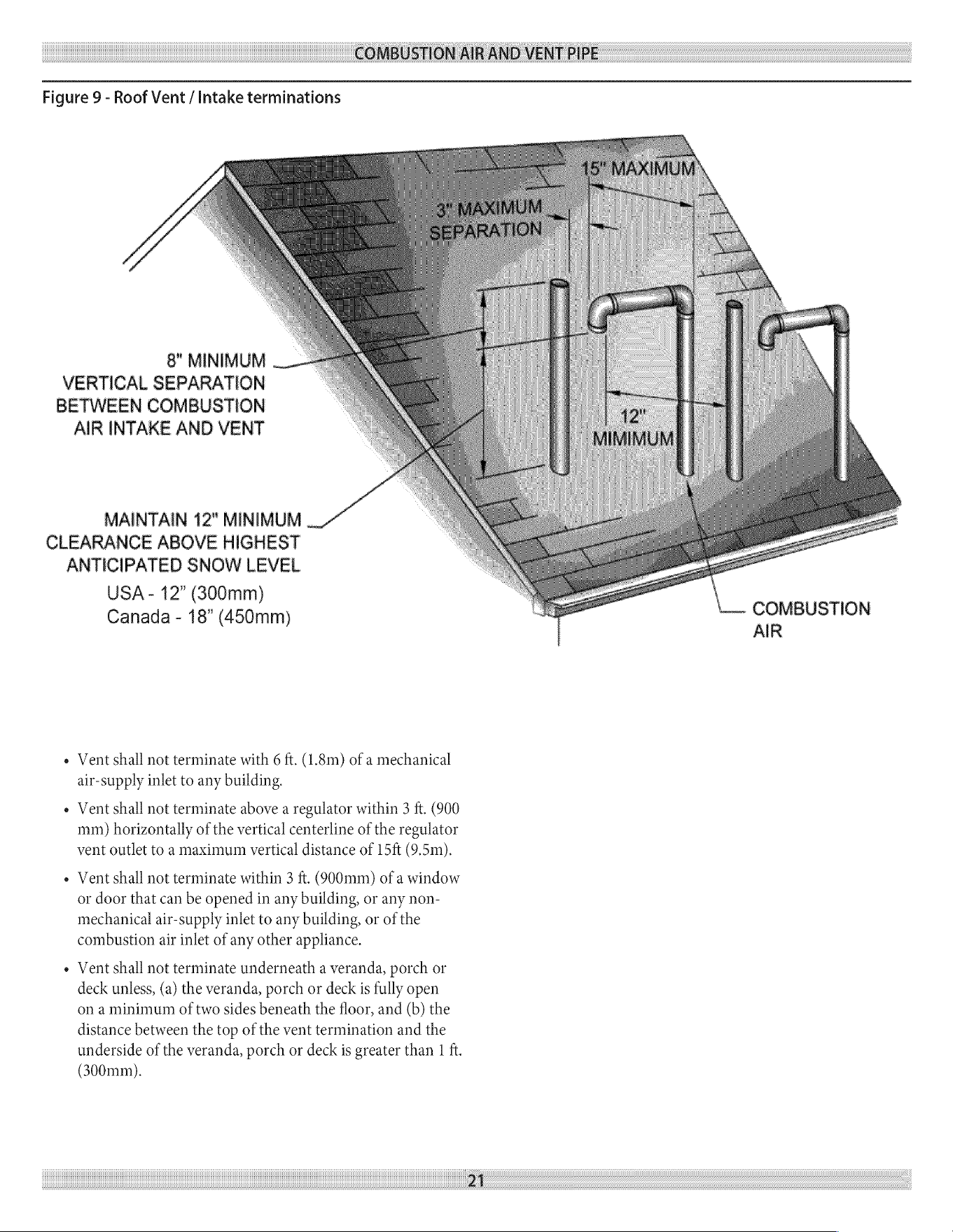
COMBUSTION
AIR
AND
VENT
PIPE
Figure
9
-
Roof
Vent
/
Intake
terminations
8"
MINIMUM
VERTICAL
SEPARATION
BETWEEN
COMBUSTION
AIR
INTAKE
AND
VENT
MAINTAIN
12"
MINIMUM
CLEARANCE
ABOVE
HIGHEST
ANTICIPATED
SNOW
LEVEL
USA
-
12”
(300mm)
Canada
-
18”
(450mm)
COMBUSTION
AIR
e
Vent
shall
not
terminate
with
6
ft.
(1.8m)
of
a
mechanical
air-supply
inlet
to
any
building.
¢
Vent
shall
not
terminate
above
a
regulator
within
3
ft.
(900
mm)
horizontally
of
the
vertical
centerline
of
the
regulator
vent
outlet
to
a
maximum
vertical
distance
of
15ft
(9.5m).
e
Vent
shall
not
terminate
within
3
ft.
(900mm)
of
a
window
or
door
that
can
be
opened
in
any
building,
or
any
non-
mechanical
air-supply
inlet
to
any
building,
or
of
the
combustion
air
inlet
of
any
other
appliance.
¢
Vent
shall
not
terminate
underneath
a
veranda,
porch
or
deck
unless,
(a)
the
veranda,
porch
or
deck
is
fully
open
on
a
minimum
of
two
sides
beneath
the
floor,
and
(b)
the
distance
between
the
top
of
the
vent
termination
and
the
underside
of
the
veranda,
porch
or
deck
is
greater
than
|
ft.
(300mm).
Zi
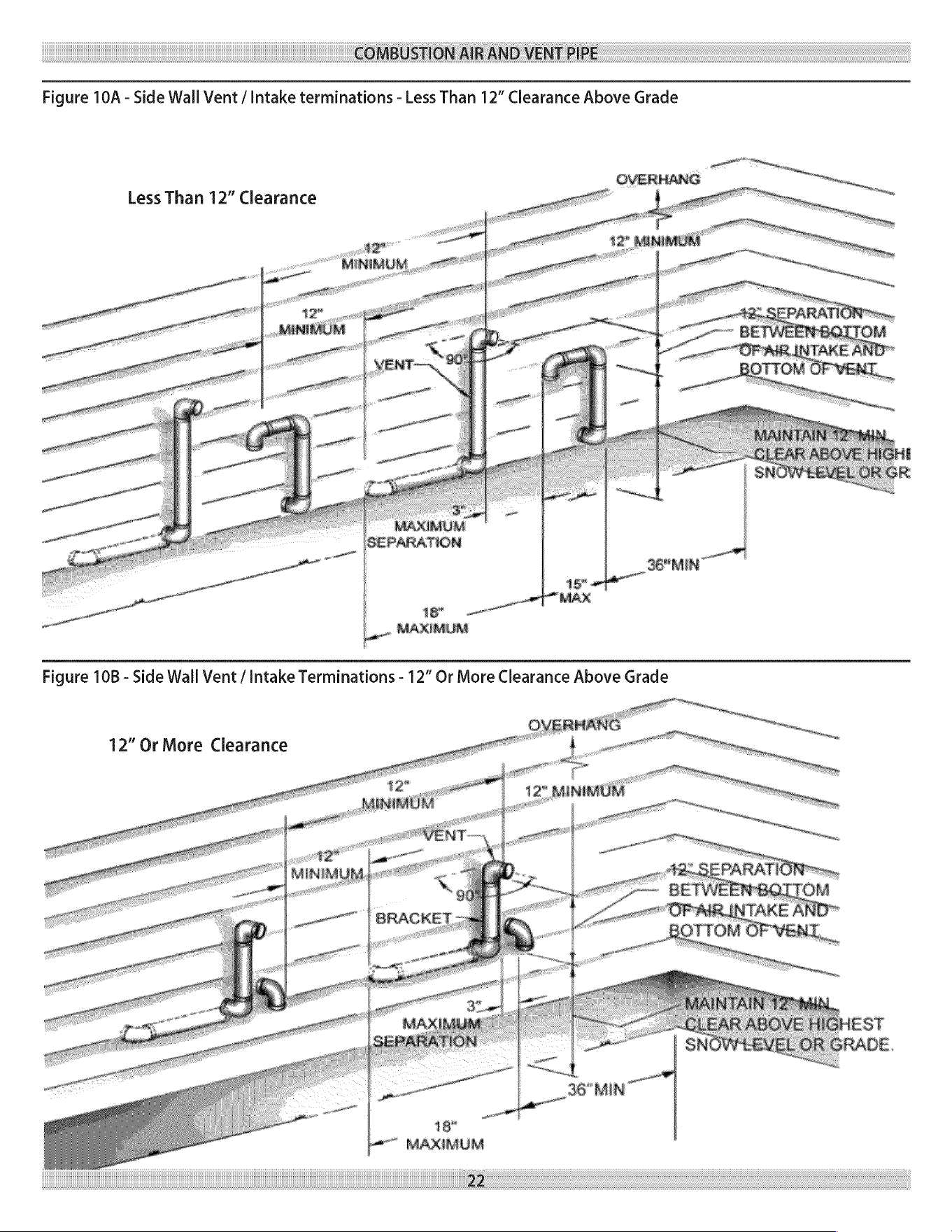
COMBUSTION
AIR
AND
VENT
PIPE
Figure
10A
-
Side
Wall
Vent
/
Intake
terminations
-
Less
Than
12”
Clearance
Above
Grade
Less
Than
12”
Clearance
oon
MINIMUM...
MAXIMUM
SEPARATION
36"MIN
ye
a é
MAX
IMUM
La
ogg
EE
Figure
10B
-
Side
Wall
Vent
/
Intake
Terminations
-
12”
Or
More
Clearance
Above
Grade
12”
Or
More
Clearance
18"
MAXIMUM
22
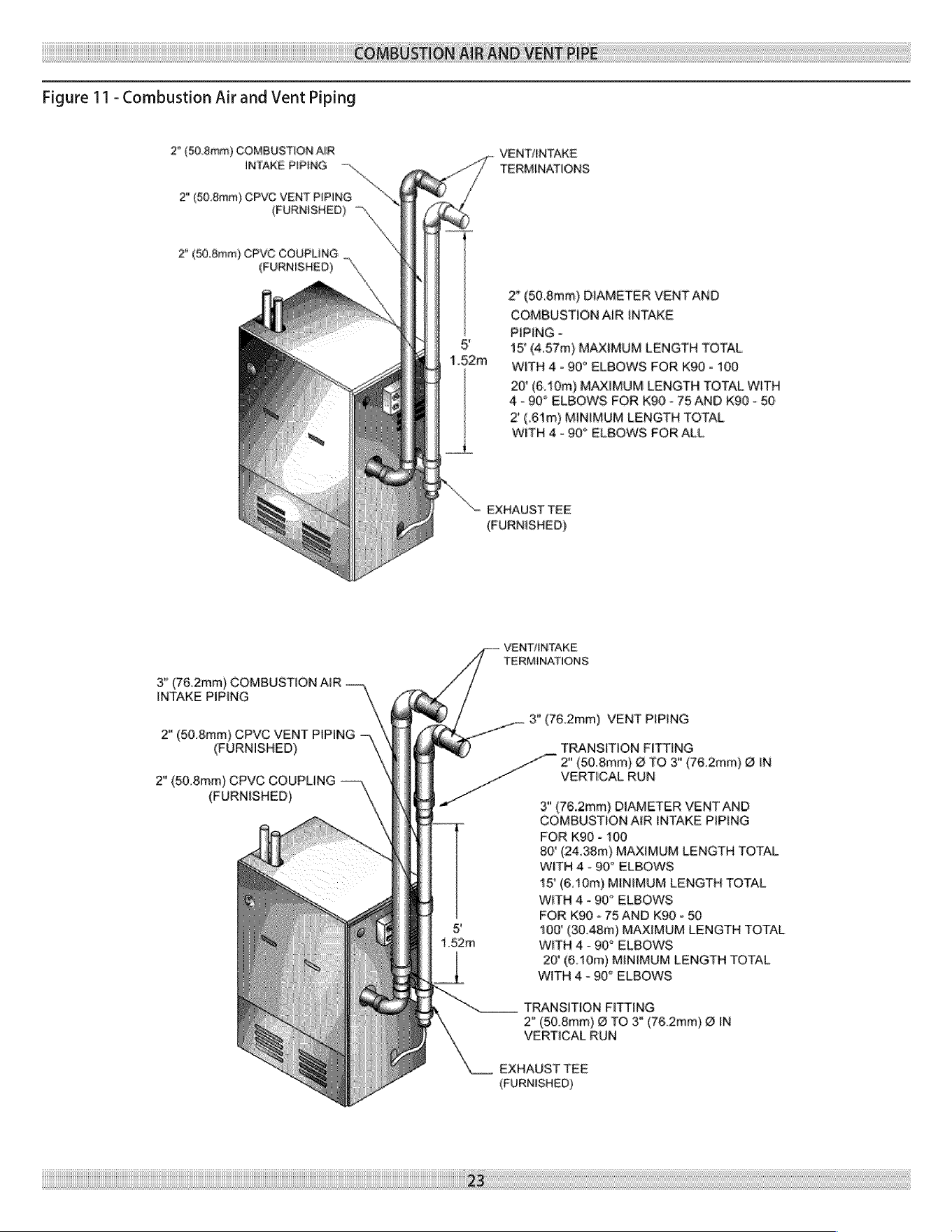
COMBUSTION
AIR
AND
VENT
PIPE
Figure
11
-
Combustion
Air
and
Vent
Piping
2"
(0.4mm)
COMBUSTION
AIR
INTAKE
PIPING
-—~,
VENTIUNTAKE
TERMINATIONS
2"
(50.8mm)
CPVG
VENT
PIPING
*
(FURNISHED)
2"
(60,.8mm)
CPVC
COUPLING
(FURNISHED)
aN
2"
(60.8mm)
DIAMETER
VENT
AND
COMBUSTION
AIR
INTAKE
PIPING
-
15°
(4.57m)
MAXIMUM
LENGTH
TOTAL
WITH
4
-
90°
ELBOWS
FOR
K90
-
100
20
(6.10m)
MAAIMUM
LENGTH
TOTAL
WITH
4-90"
ELBOWS
FOR
K90
-
75
AND
KQ0
-
50
2'
(.61m)
MINIMUM
LENGTH
TOTAL
WITH
4
-
90°
ELBOWS
FOR
ALL
“Se
EXHAUST
TEE
(FURNISHED)
VENTANTAKE
TERMINATIONS
3"
(76.2mm)
COMBUSTION
AIR
INTAKE
PIPING
3"
(76.2mm)
VENT
PIPING
2"
(60.8mm)
CPVC
VENT
PIPING
(FURNISHED)
TRANSITION
FITTING
2"
(508mm)
@
TO
3"
(76.2mm)
@
IN
2”
(0.8mm)
CPVC
COUPLING
VERTICAL
RUN
(FURNISHED)
3"
(76.2mm)
DIAMETER
VENT AND
COMBUSTION
AIR
INTAKE
PIPING
FOR
K90
-
100
80"
(24.38m)
MAXIMUM
LENGTH
TOTAL
WITH
4
-
90°
ELBOWS
15°
(6.10m)
MINIMUM
LENGTH
TOTAL
WITH
4
-
90°
ELBOWS
FOR
K90
-
75
AND
K90
-
50
100°
(30.48m)
MAXIMUM
LENGTH
TOTAL
WITH
4
-
90°
ELBOWS
20'
(6.10m)
MINIMUM
LENGTH
TOTAL
WITH
4
-
90°
ELBOWS
TRANSITION
FITTING
2"
(50.8mm)
@
TO
3°
(76.2mm)
@
IN
VERTICAL
RUN
EXHAUST
TEE
(FURNISHED)
23
COMBUSTION
AIR
AND
VENT
PIPE
Installation
7.
After
pipes
have
been
cut
and
pre-assembled,
apply
cement
1.
Attach
combustion
air
intake
piping
to
supplied
Fernco
2”
cou-
primer
to
pipe
fitting
socket
and
end
of
pipe
to
insertion
mar
k
pling
on
mixer.
Attach
vent
piping
to
furnished
2”
CPVC
vent
Quickly
apply
approved cement
to
end
of
pipe
and
fitting
tee
on
draft
inducer
outlet,
socket
(over
primer).
Apply
cement
in
light,
uniform
coat
on
the
inside
of
socket
to
prevent
buildup
of
excess
cement.
Apply
NOTICE
second
coat.
All
pipe
joints
are
to
be
water
tight
8.
While
cement
is
still
wet,
insert
pipe
into
socket
with
4%
turn
twist.
Be
sure
pipe
is
fully
inserted
into
fitting
socket.
2.
Working
from
the
boiler
to
the
outside,
cut
pipe
to
required
; . ;
9.
Wipe
excess
cement
from
joint.
A
continuous
bead
of
cement
length(s).
. . .
..
will be
visible
around
perimeter
of
a
properly
made
joint.
3.
Deburr
inside
and
outside
of
pipe.
-
10.
Handle
pipe
joint
carefully
until
cement
sets.
4.
Chamfer
outside
edge
of
pipe
for
better
distribution
of
primer
Lo,
a
we
11.
Support
combustion
air
and
vent
piping
a
minimum
of
and
cement.
.
-
every
5
feet
using
pre-formed
metal
hanging
straps.
Do
not
5.
Clean
and
dry
all
surfaces
to
be
joined.
rigidly
support
pipes.
Allow
movement
due
to
expansion
and
Check
dry
fit
of
pipe
and
mark
insertion
depth
on
pipe.
contraction.
NOTICE
12.
Slope
horizontal
portion
of
combustion
air
and
vent
pipes
toward
boiler
a
minimum
of
4”
per
linear
ft.
(21mm/m)
with
It
is
recommended
that
all
pipes
be
cut,
no
sags
between
hangers.
prepared,
ane
menting
2
bled
mere
re
13.
Use
appropriate
methods
to
seal
openings
where
vent
and
permanentiy
cementing
any
joint.
combustion
air
pipes
pass
through
roof
or
side
wall.
GAS
SUPPLY
PIPING
Check
Gas
Supply
.
.
th
boil
be
th
size
for
the
lenoth
Use
only
those
piping materials
and
joining
methods
listed
f f
Bas
oe
to
bo
Bin
ee
ene
tof,
he.
il
€
tens
as
acceptable
by
the
authority
having
jurisdiction,
or
in
the
orrun
an
or
the
ad
tu
ene
tbl
a
f,
h
gas
ull
ization
absence
of
such
requirements,
by
the
National
Fuel
Gas
Code,
equipment
connecte
tout
ce
Fable
#2
tor
the
proper
size
(next
ANSI
Z223.1/NFPA
54
and
or
the
Natural
Gas
and
Propane
page).
Be sure
your
gas
line
complies
with
local
codes
and
gas
Installation
Code,
CAN/CSA
B149.1
company
requirements.
,
oo
oo
Use
pipe
joint
compound
suitable
for
liquefied
petroleum
gas
The
boiler
and
its
individual
shutoff
valve
must
be
disconnected
on
male
threads
only
from
the
gas
supply
piping
system during
any
pressure
testing
of
dio;
-
that
system
at
test
pressures
in
excess
of
%
psig
(3.5kpa).
Use
ground
joint
unions.
The
boiler
must
be
isolated
from
the gas
supply
piping
system
by
Install
a
sediment
trap
upstream
of
gas
controls.
closing
its
individual
manual
shutoff
valve
during
any
pressure
Use
two
pipe
wrenches
when
making
the
connection
to
the gas
testing
of
the gas
supply
piping
system
at
test
pressures
equal
to
or
valve
to
keep
it
from
turning.
less
than
%
psig
(3.50ka).
6.
Install
a
manual
shutoff
valve
in
the
vertical
pipe
about
5
feet
NATURAL
|
PROPANE
above
floor.
GAS GAS
7.
Tighten
all
joints
securely.
MAXIMUM
GAS
SUPPLY
40’
we.
14”
we.
8.
Propane
gas
connections
should
only
be
made
by
a
licensed
PRESSURE
propane
installer.
aa
enEScy
wt
4’
we.
40”
we.
9.
Two
stage
regulation
should
be
used
by
the
propane
installer.
10.
Propane
gas
piping
should
be
checked
out
by
the
propane
Connecting
The
Gas
Piping
Refer
to
Figure
12
(on
following
page)
for
the
general
layout
at
the
boiler.
It
shows
the
basic
fittings
you
will
need.
The
gas
line
enters
the
boiler
from
the
right
side
jacket panel.
The
boiler
may
receive
the gas
supply
pipe
through
the
left
side,
or
rear
jacket
panel
by
relocating
the gas
valve
connector
and
pipe
assembly.
The
boiler
is
equipped
with
a
%”
NPT
connection
on
the
gas
valve
for
supply
piping.
The
following
rules
apply:
24
installer.
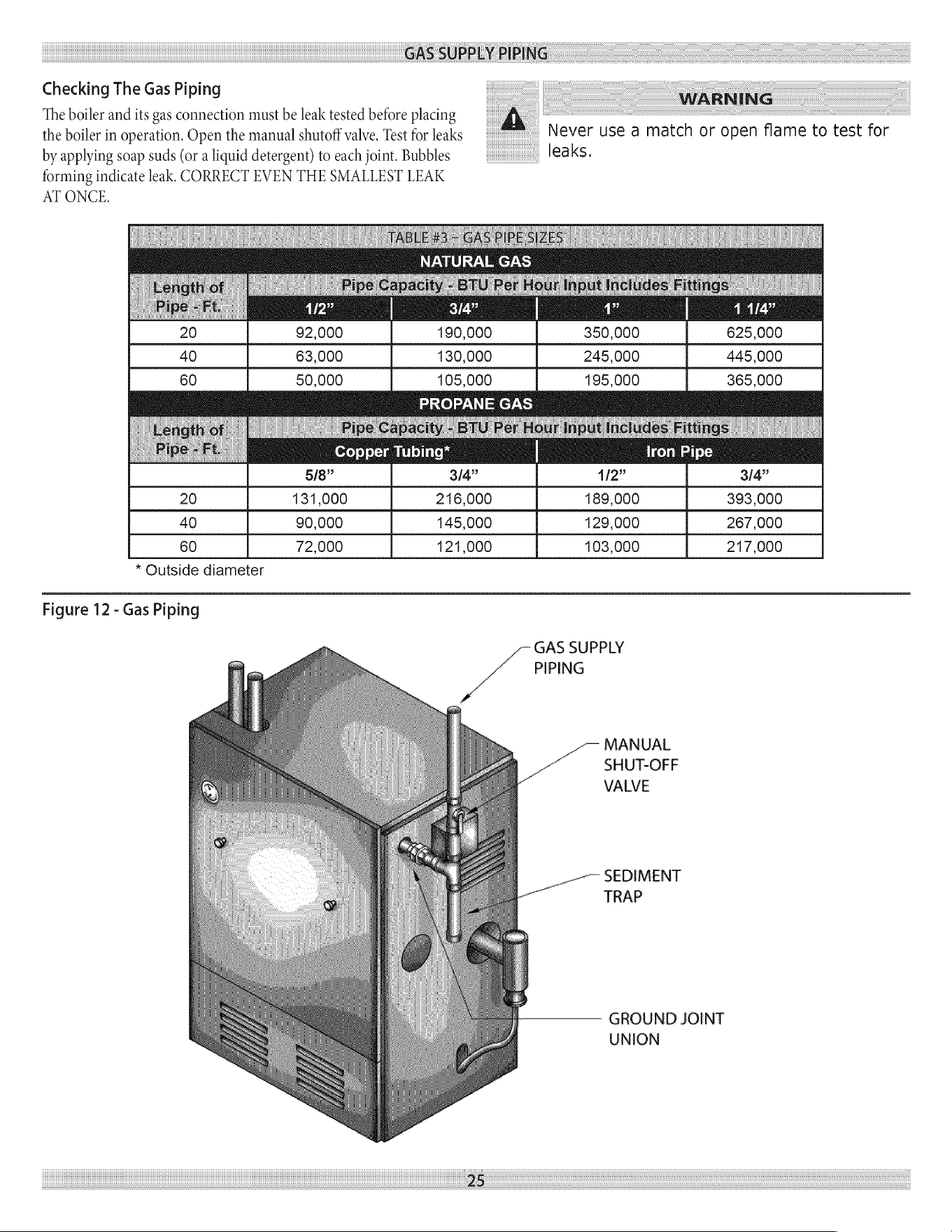
GAS
SUPPLY
PIPING
Checking
The
Gas
Piping
The
boiler
and
its
gas
connection
must
be
leak
tested
before
placing
the
boiler
in
operation.
Open
the
manual
shutoff
valve.
Test
for
leaks
by
applying
soap
suds
(or
a
liquid
detergent)
to
each
joint.
Bubbles
forming
indicate
leak.
CORRECT
EVEN
THE
SMALLEST
LEAK
AT
ONCE.
WARNING
Never
use
a
match
or
open
flame
to
test
for
leaks.
NATURAL
GAS
ey
20
92,000
190,000
350,000 625,000
40
63,000
130,000
245,000 445,000
60
50,000
105,000 195,000
365,000
PROPANE
GAS
Copper
Tubing”
Iron
Pipe
5/8” 3/4”
4/2”
3/4”
20
131,000
216,000
189,000
393,000
40
90,000
145,000
129,000
267,000
60
72,000
121,000
103,000
217,000
*
Outside
diameter
Figure
12
-
Gas
Piping
GAS
SUPPLY
PIPING
MANUAL
SHUT-OFF
VALVE
__--——
SEDIMENT
-
TRAP
UNION
29
GROUND
JOINT
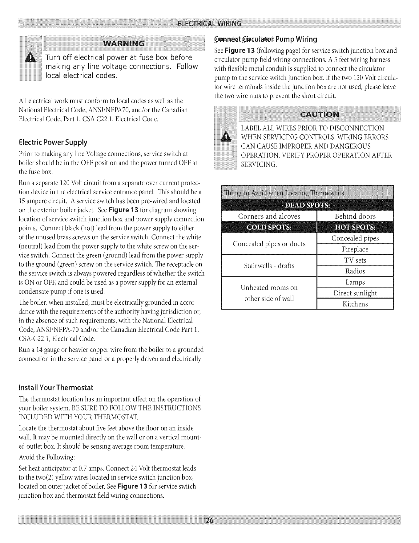
ELECTRICAL
WIRING
WARNING
A
Turn
off
electrical
power
at
fuse
box
before
making
any
line
voltage
connections.
Follow
local
electrical
codes.
All
electrical
work
must
conform
to
local
codes
as
well
as
the
National
Electrical
Code,
ANSI/NFPA70,
and/or
the
Canadian
Electrical
Code,
Part
1,
CSA
C22.1,
Electrical
Code.
Electric
Power
Supply
Prior
to
making
any
line
Voltage
connections,
service
switch
at
boiler
should
be
in
the
OFF
position
and
the
power
turned
OFF
at
the
fuse
box.
Run
a
separate
120
Volt
circuit
from
a
separate
over
current
protec-
tion
device
in
the
electrical
service
entrance
panel.
This
should
be
a
15
ampere
circuit.
A
service
switch
has
been
pre-wired
and
located
on
the
exterior
boiler
jacket.
See
Figure
13
for
diagram showing
location
of
service
switch
junction
box
and
power
supply
connection
points.
Connect
black
(hot)
lead
from
the
power
supply
to
either
of
the
unused
brass
screws
on
the
service
switch.
Connect
the
white
(neutral)
lead
from
the
power
supply
to
the
white
screw
on
the
ser-
vice
switch.
Connect
the
green
(ground)
lead
from
the
power
supply
to
the
ground
(green)
screw
on
the
service
switch.
The
receptacle
on
the
service
switch
is
always
powered
regardless
of
whether
the
switch
is
ON
or
OFE
and
could
be
used
as
a
power
supply
for
an
external
condensate
pump
if
one
is
used.
The
boiler,
when
installed,
must
be
electrically
grounded
in
accor-
dance
with
the
requirements
of
the
authority
having
jurisdiction
or,
in
the
absence
of
such
requirements,
with
the
National
Electrical
Code,
ANSI/NFPA-70
and/or
the
Canadian
Electrical
Code
Part
1,
CSA-C22.1,
Electrical
Code.
Run
a
14
gauge
or
heavier
copper
wire
from
the
boiler
to
a
grounded
connection
in
the
service
panel
or
a
properly
driven
and
electrically
install
Your
Thermostat
The
thermostat
location
has
an
important
effect
on
the
operation
of
your
boiler
system.
BE
SURE
TO
FOLLOW
THE
INSTRUCTIONS
INCLUDED
WITH YOUR
THERMOSTAT.
Locate
the
thermostat
about
five
feet
above
the
floor
on
an
inside
wall.
It
may
be
mounted
directly
on
the
wall
or
on
a
vertical
mount-
ed
outlet
box.
It
should
be
sensing average
room
temperature.
Avoid
the
Following:
Set
heat
anticipator
at
0.7
amps.
Connect
24
Volt
thermostat
leads
to
the
two(2) yellow
wires
located
in
service
switch
junction
box,
located
on
outer
jacket
of
boiler.
See
Figure
13
for
service
switch
junction
box
and
thermostat
field
wiring
connections.
26
Gonnéat
Givculatel
Pump
Wiring
See
Figure
13
(following
page)
for
service
switch
junction
box
and
circulator
pump
field
wiring
connections.
A
5
feet
wiring
harness
with
flexible
metal
conduit
is
supplied
to
connect
the
circulator
pump
to
the
service
switch
junction
box.
If
the
two
120
Volt
circula-
tor
wire
terminals
inside
the
junction
box
are
not
used,
please
leave
the
two
wire
nuts
to
prevent
the
short
circuit.
CAUTION
LABEL
ALL
WIRES
PRIOR
TO
DISCONNECTION
A
WHEN
SERVICING
CONTROLS.
WIRING
ERRORS
CAN
CAUSE
IMPROPER
AND
DANGEROUS
OPERATION.
VERIFY
PROPER
OPERATION
AFTER
SERVICING.
DEAD
SPOIS:
Behind
doors
COLD
SPOTS:
HOT
SPOTS:
C led
pi
Concealed
pipes
or
ducts
—
pe
Fireplace
TV
set
Stairwells
-
drafts
~<
:
Radios
L
Unheated
rooms
on
—
Direct
sunlight
other
side
of
wall
-
Kitchens
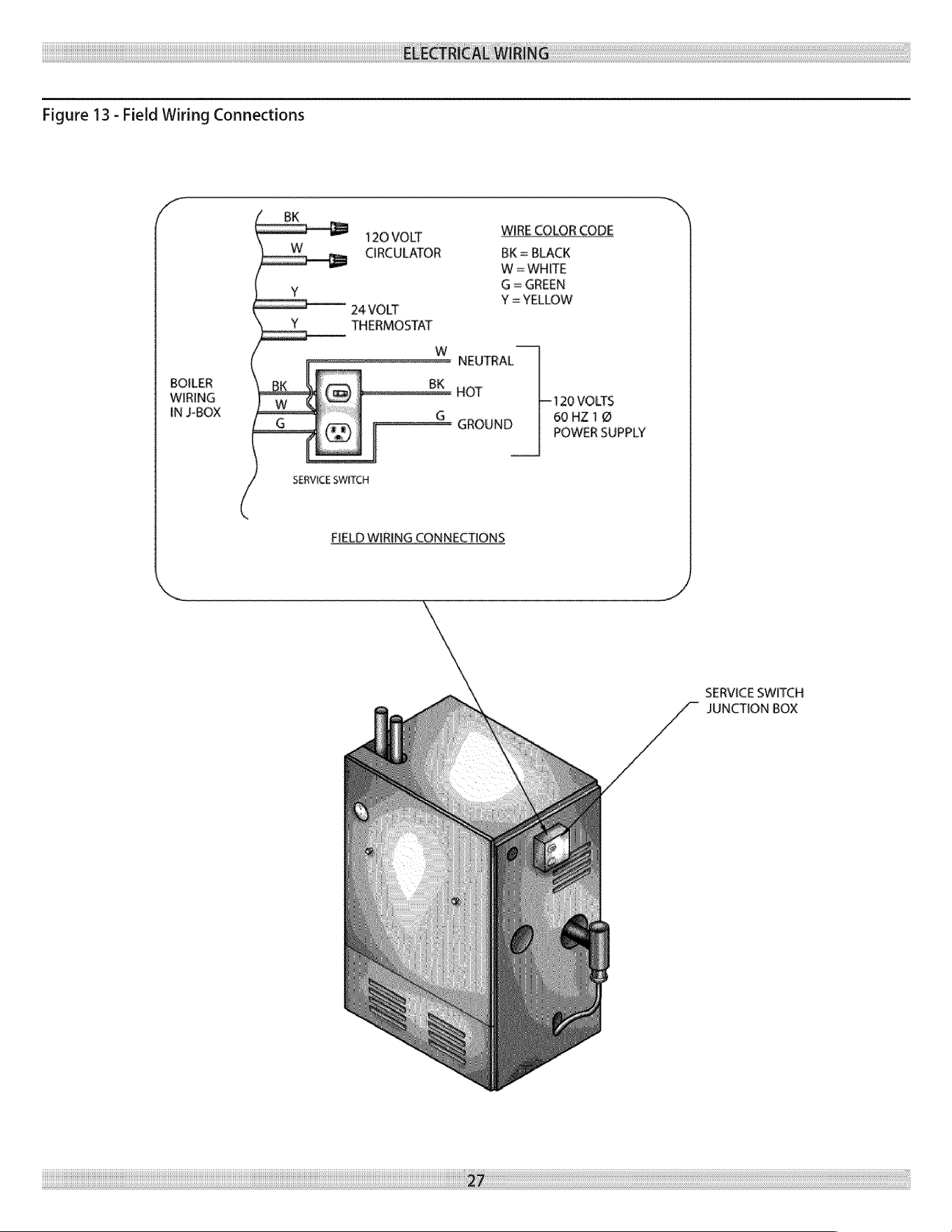
ELECTRICAL
WIRING
Figure
13
-
Field
Wiring
Connections
120
VOLT
WIRE
COLOR
CODE
CIRCULATOR
BK
=
BLACK
oe
on
24
VOLT
THERMOSTAT
NEUTRAL
BOILER
p
BK
WIRING
—
:
INJ-BOX
=
=
—y
G
HOT
120
VOLTS
60HZ1@
GROUND
POWER
SUPPLY
SERVICE
SWITCH
FIELD
WIRING
CONNECTIONS
SERVICE
SWITCH
JUNCTION
BOX
2/
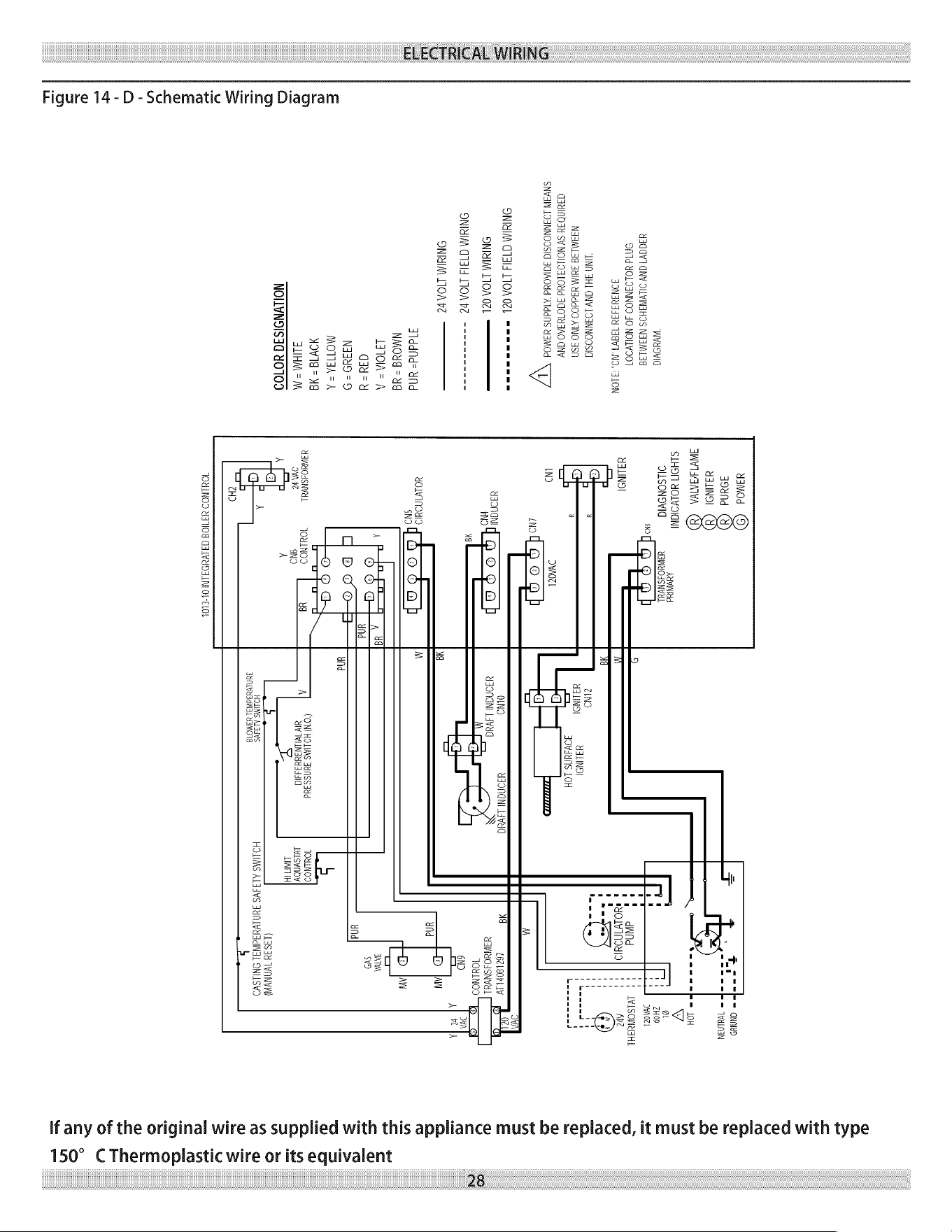
ELECTRICAL
WIRING
Figure
14
-
D
-
Schematic
Wiring
Diagram
Wvddvid
UadGV7
GNV
OLWWAHOS
NASM
138
OMId
YOLOANNOOD
JO
NOLLV9OT
SONSUSITY
T38V7
NO.
SLON
“LIND
FHL
GNY
LOINNOOSIG
N3IMLI9
JUIM
dddOO
AINO
Jsn
CAMINDAY
SV
NOILOSLONd
SCOTYIAO
CNY
SNVAW
LOSNNOOSIG
FGIAOUd
‘AlddNS
YAMOd
VV
ONTIM
(141d
DOA
O¢L
sss
ONIMIM
TOA
cL
ONIMIM
(T4ld
LIOA
Pe
-- >a nn
roo
ONTMIM
LIOA
be
Alddfd=
ud
NMOUd
=
ud
LFIOIA=
A
ddd
=
4
Nadu
=
9
MOTISA=A
WOWTd
=
Hg
ALIHM
=
M
NOILVNOISSG
YO109
yimod
©)
yound
Gd)
MALINS!
CH)
INYISAATWA
CS)
SLHOIT
MOLWOIONI
Anne
OILSONOVIG
USWYOISNYYL
=
GONADS
=
WHLNIN
=
10H
Vv
gl
ZHO09
DAZ
L
IVISOWUIHL
ND
1
dANd
reo
LVINOUI9
ne)
Ya
LINO|
2iNO
NAHINOI
UALIND!
JOWANNS
LOH
DVAOZL
©
YSONGNE
LAVad
OLND
UsONGN
Lived
LOCL80PL
LY
UaWeOISNVaL
OULNOD
daONGNi
PND
©
Ma
YOLVINYID.
SNO
B
CO'N)
HOLIMS
FUASS3Ud
MY
TVLLNSNUS
31
UaWYOASNVYL
TOULNOD
OVA
Fe
SND
A
LUATT
(LIS3u
TANYA)
HOLIMS
ALSAVS
JUN
LVasadWAL
ONIESYO
HOLMS
ALSIVS
SUALVESdNGL
UaMO7g
CHD
JOULNOD
YITION
GALVYOALNI
OL-ELOL
if
any
of
the
original
wire
as
supplied
with
this
appliance
must
be
replaced,
it
must
be
replaced
with
type
150°
C
Thermoplast
its
equivalent
ic
wire
Ori
28
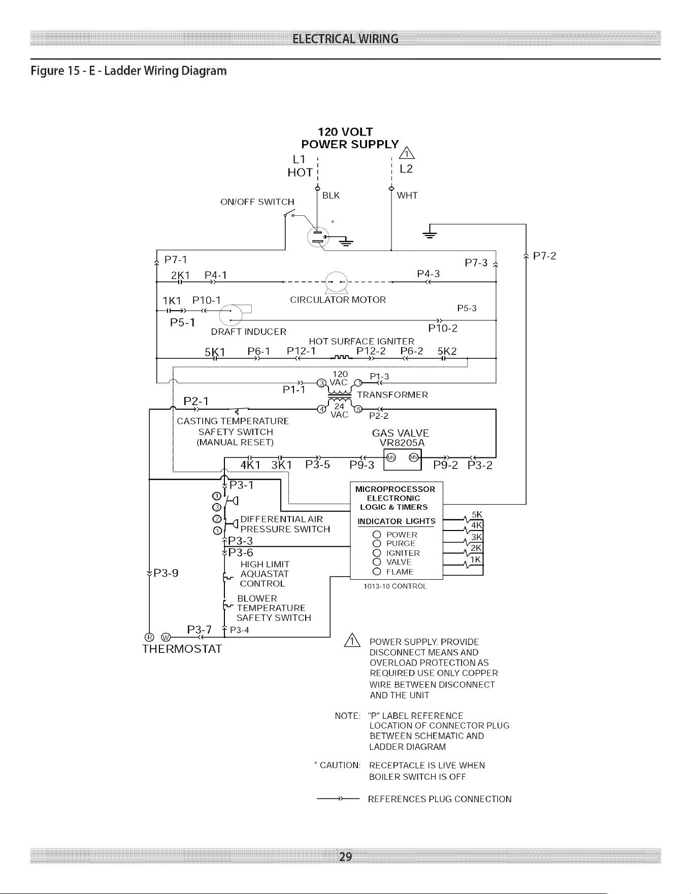
ELECTRICAL
WIRING
Figure
15
-
E-
Ladder
Wiring
Diagram
120
VOLT
POWER
SUPPLY
L1
;
HOT
!
1
Le
nn
WHT
ON/OFF
SWITCH
(sr
—
a7
=
~
b
p71
2K1
P4-1
{$4
p>
—_____+
-----
Louk
1K1.
P10-1
|
CIRCULATOR
MOTOR
th)
<<
PS-3
P5-1
\=
DRAFT
INDUCER
P10-2
HOT
SURFACE
IGNITER
5K1
P6-1
P12-1
P12-2
P6-2
5K2
1F
SUL.
1t
’
120
.
P1-1
Ax
TRANSFORMER
|
P2-1
34
q
yvac
Ops
CASTING
TEMPERATURE
SAFETY
SWITCH
GAS
VALVE
(MANUAL
RESET)
VR8205A
tt
1t
—
@
i
ak
aka
P35
psa
[OT
pss Poe
t
P3-1
MICROPROCESSOR
@
ELECTRONIC
©
LOGIC
&
TIMERS
@‘_,DIFFERENTIALAIR
INDICATOR
LIGHTS
*
@]
“PRESSURE
SWITCH
©
POWER
pe3-3
Q
PURGE
P3-6
©
IGNITER
HIGH
LIMIT
©
VALVE
uK
P3-9
AQUASTAT
O
FLAME
CONTROL
1013-10
CONTROL
BLOWER
TEMPERATURE
SAFETY SWITCH
P3-7
fF
P3-4
® @
Z\,
POWER
SUPPLY.
PROVIDE
THERMOSTAT
DISCONNECT
MEANS
AND
OVERLOAD
PROTECTION
AS
REQUIRED
USE
ONLY
COPPER
WIRE
BETWEEN
DISCONNECT
AND
THE
UNIT
"P"
LABEL
REFERENCE
LOCATION
OF
CONNECTOR
PLUG
BETWEEN
SCHEMATIC
AND
LADDER
DIAGRAM
NOTE:
RECEPTACLE
IS
LIVE
WHEN
BOILER
SWITCH
IS
OFF
*
CAUTION:
REFERENCES
PLUG
CONNECTION
29
P7-2
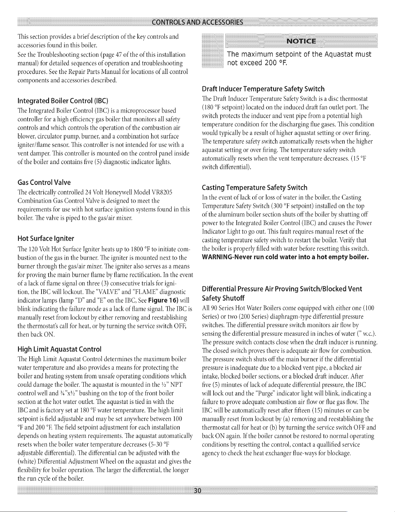
CONTROLS
AND
ACCESSORIES
This
section
provides
a
brief
description
of
the
key
controls
and
accessories
found
in
this
boiler.
See
the
Troubleshooting
section
(page
47
of
the
of
this
installation
manual)
for
detailed
sequences
of
operation
and
troubleshooting
procedures.
See
the
Repair
Parts
Manual
for
locations
of
all
control
components
and
accessories
described,
Integrated
Boiler
Control
(IBC)
The
Integrated
Boiler
Control
(IBC)
is
a
microprocessor
based
controller
for
a
high
efficiency
gas
boiler
that
monitors
all
safety
controls
and
which
controls
the
operation
of
the
combustion
air
blower,
circulator
pump,
burner,
and
a
combination
hot
surface
igniter/flame
sensor.
This
controller
is
not
intended
for
use
with
a
vent
damper.
This
controller
is
mounted
on
the
control
panel
inside
of
the
boiler
and
contains
five
(5)
diagnostic
indicator
lights.
Gas
Control
Valve
The
electrically
controlled
24
Volt
Honeywell
Model
VR8205
Combination
Gas
Control
Valve
is
designed
to
meet
the
requirements
for
use
with
hot
surface
ignition
systems
found
in
this
boiler.
The
valve
is
piped
to
the
gas/air
mixer.
Hot
Surface
Igniter
The
120
Volt
Hot
Surface
Igniter
heats
up
to
1800
°F to
initiate
com-
bustion
of
the gas
in
the
burner.
The
igniter
is
mounted
next
to
the
burner
through
the
gas/air
mixer.
The
igniter
also
serves
as
a
means
for
proving
the
main
burner
flame
by
flame
rectification.
In
the
event
of
a
lack
of
flame
signal
on
three
(3)
consecutive
trials
for
igni-
tion,
the
IBC
will
lockout.
The
“VALVE”
and
“FLAME”
diagnostic
indicator
lamps
(lamp
“D”
and
“E”
on
the
IBC,
See
Figure
16)
will
blink
indicating
the
failure
mode
as
a
lack
of
flame
signal.
The
IBC
is
manually
reset
from
lockout
by
either
removing
and
reestablishing
the
thermostat’s
call
for
heat,
or
by
turning
the
service
switch
OFF,
then
back
ON.
High
Limit
Aquastat
Control
The
High
Limit
Aquastat
Control
determines
the
maximum
boiler
water
temperature
and
also
provides
a
means
for
protecting
the
boiler
and
heating
system
from
unsafe
operating
conditions
which
could
damage
the boiler.
The
aquastat
is
mounted
in
the
2”
NPT
control
well
and
%4°x'2”
bushing
on
the
top
of
the
front
boiler
section
at
the
hot
water
outlet.
The
aquastat
is
tied
in
with
the
IBC
and
is
factory
set
at
180
°F
water
temperature.
The
high
limit
setpoint
is
field
adjustable
and
may
be
set
anywhere
between
100
°F
and
200
°F,
The
field
setpoint
adjustment
for
each
installation
depends
on
heating
system
requirements.
The
aquastat
automatically
resets
when
the
boiler
water
temperature
decreases
(5-30
°F
adjustable
differential).
The
differential
can
be
adjusted
with
the
(white)
Differential
Adjustment
Wheel
on
the
aquastat
and
gives
the
flexibility
for
boiler
operation.
The
larger
the
differential,
the
longer
the
run
cycle
of
the
boiler.
30
NOTICE
The
maximum
setpoint
of
the
Aquastat
must
not
exceed
200
°F.
Draft
Inducer
Temperature
Safety
Switch
The
Draft
Inducer
Temperature
Safety
Switch
is
a
disc
thermostat
(180
°F
setpoint)
located
on
the
induced
draft
fan
outlet
port.
The
switch
protects
the
inducer
and
vent
pipe
from
a
potential
high
temperature
condition
for
the
discharging
flue
gases.
This
condition
would
typically
be
a
result
of
higher
aquastat
setting
or
over
firing.
The
temperature
safety
switch
automatically
resets
when
the
higher
aquastat
setting
or
over
firing.
The
temperature
safety
switch
automatically
resets
when
the
vent
temperature
decreases.
(15
°F
switch
differential).
Casting
Temperature
Safety
Switch
In
the
event
of
lack
of or
loss
of
water
in
the
boiler,
the
Casting
Temperature
Safety
Switch
(300
°F
setpoint)
installed
on
the
top
of
the
aluminum
boiler
section
shuts
off
the
boiler
by
shutting
off
power
to
the
Integrated
Boiler
Control
(IBC)
and
causes
the
Power
Indicator
Light
to
go
out.
This
fault
requires
manual
reset
of
the
casting
temperature
safety
switch
to
restart
the
boiler.
Verify
that
the
boiler
is
properly
filled
with
water
before
resetting
this
switch.
WARNING-Never
run
cold
water
into
a
hot
empty
boiler.
Differential
Pressure
Air
Proving
Switch/Blocked
Vent
Safety
Shutoff
All 90
Series
Hot
Water
Boilers
come
equipped
with
either
one
(100
Series)
or
two
(200
Series)
diaphragm-type
differential
pressure
switches.
The
differential
pressure
switch
monitors
air
flow
by
sensing
the
differential
pressure
measured
in
inches
of
water
(”
w.c.).
The
pressure
switch
contacts
close
when
the
draft
inducer
is
running.
The
closed
switch
proves
there
is
adequate
air
flow
for
combustion.
The
pressure
switch
shuts
off
the
main
burner
if
the
differential
pressure
is
inadequate
due
to
a
blocked
vent
pipe,
a
blocked
air
intake,
blocked
boiler
sections,
or
a
blocked
draft
inducer.
After
five
(5)
minutes
of
lack
of
adequate
differential
pressure,
the
IBC
will
lock
out
and
the
“Purge”
indicator
light
will
blink,
indicating
a
failure
to
prove
adequate
combustion
air
flow
or
flue
gas
flow.
The
IBC
will be
automatically
reset
after
fifteen
(15)
minutes
or
can
be
manually
reset
from
lockout
by
(a)
removing
and
reestablishing
the
thermostat
call
for
heat
or
(b)
by
turning
the
service
switch
OFF
and
back
ON
again.
If
the
boiler
cannot
be
restored
to
normal
operating
conditions
by
resetting
the
control,
contact
a
quallified
service
agency
to
check
the
heat
exchanger
flue-ways
for
blockage.
CONTROLS
AND
Draft
Inducer
The
draft
inducer
(blower)
provides
a
means
for
pulling
combustion
air
into
and
through
the
mixer,
the
burner,
the
flue
ways
of
the
cast
aluminum
boiler
sections
and
the
flue
adapter
before
being
discharged
through
the
vent
piping
to
the
outdoors.
See
applicable
sections
for
proper
sizing
and
installation
of
combustion
air
and
vent
piping
in
this
manual.
Circulator
Pump
Every
forced
hot
water
system
requires
at
least
one circulating
pump.
The
circulating
pump
imparts
the
necessary
energy
to
move
the
water
through
the
closed
loop
supply
and
return
piping
systems,
terminal
heating
equipment
(ie.
finned
tube
radiators,
etc.)
and
back
through
the
boiler
for
reheating.
To
provide
the
required
hot
water
flow
rates,
the
circulator
pump
must
be
properly
sized
to
overcome
frictional
losses
(usually
measured
in
feet
of
water,
also
referred
to
as
“pump
head
loss”)
of
the
supply
and
return
piping
systems
and
boiler.
The
circulator
pump
is
furnished
in
a
carton
within
the
boiler
cabinet
for
a
single
zone
or
zone
valve
controlled
heating
system
and
should
be
correctly
located
on
the
downstream
(i.e.,
pumping
away)
side
of
the
expansion
tank.
For
a
pump
controlled
system (where
there
is
a
circulator
for
each
zone)
the
circulator
provided
with
the
boiler
can
work
for
one
zone.
For
more
details
on
piping
and
circulators,
see
Near
Boiler
Piping
section
(page
12
of
this
manual).
Drain
Valve
The
manual
drain
valve
provides
a
means
of
draining
the
water
in
the
heating
system,
including
the
boiler
and
hot
water
supply
and
return
piping
systems
installed
above
the
drain
valve.
This
drain
valve
is
installed
in
the
%4”
tapping
at
the
bottom
of
the
front
boiler
section.
Any
piping
installed
below
the
elevation
of
this
drain
valve
will
require
additional
drain
valves
to
be
installed
at
low
points
in
the
piping
systems
in
order
to
drain
the
entire
system.
A.S.M.E.
Rated
Pressure
Relief
Valve
Each
boiler
must
have
a
properly
sized
and
installed
American
Society
of
Mechanical
Engineers
rated
pressure
relief
valve.
Water
expands
as
it
is
heated
by
the
burner/boiler
sections.
If
there
is
no
place
for
the
water
to
expand
its
volume,
(i.e.
a
properly
sized
and
properly
functioning
expansion
tank)
pressure
on
the
inside
of
the
boiler
and
heating
system
will
increase.
The
furnished
relief
valve
will
automatically
open
at
30
psig
pressure
to
relieve
the
strain
on
the
boiler
and
heating
system
from
the
increasing
pressure.
The
pressure
relief
valve
discharge
must
be
piped
with
piping
same
size
as
the
valve
discharge
opening
to
an
open
drain,
tub
or
sink,
or
other
suitable
drainage
point
not
subject
to
freezing,
in
accordance
with
A.S.MLE.
specifications.
Failure
to
provide
the
pressure
relief
valve
with
piping
as
herein
described
may
cause
water
damage
and/or
serious
bodily
injury.
The
boiler
manufacturer
is
not
responsible
for
any
water
damage
or
personal
injury.
3
ACCESSORIES
Blocked
Vent
Safety
Shutoff
This
boiler
is
equipped
with
a
blocked
vent
safety
shutoff
means,
which
shuts
off
main
burner
gas
in
the
event
that
the
flow
of
combustion
products
through
the
flueways
is
reduced.
In
the
event
of
blocked
flueways,
enough
air
will
not
be
available
to
support
combustion,
and
the
$9301
Integrated
Boiler
Control
(IBC)
will
lockout
due
to
loss
of
adequate
air
flow
(after
3
trials
for
ignition).
The
“PURGE”
diagnostic
indicator
lamp
(lamp
“B”
on
the
IBC,
see
Figure
16)
will
blink
indicating
the
failure
mode
as
a
lack
of
adequate
air
flow.
The
IBC
is
manually
reset
from
lockout
by
either
removing
and
re-establishing
the
thermostat’s
call
for
heat,
or
by
turning
the
service
switch
OFF,
then
back
ON.
If
the
boiler
cannot
be
restored
to
normal
operating
condition
by
resetting
the
control,
contact
a
qualified
service
agency
to
check
heat
exchanger
flueways
for
blockage.
External
Condensate
Pump
(Optional)
For
installations
where
there
is
no
floor
drain
or
other
appropriate
drainage
receptacle
available
to
receive
condensate
from
the
boiler,
an
external
float
activated
condensate
pump
with
integral
sump
is
required.
This
unit
can
be
installed
to
pump
the
condensate
to
a
remote
tie
in
point
to
a
sanitary
sewer
system.
For
this
application,
the
boiler
must
be
installed
so
that
proper
pitch
of
piping
to
the
external
condensate
reservoir
(sump)
can
be
accomplished.
Use
wood
frame
or
blocks
to
raise
boiler
as
required
for
proper
installation.
WATER
TREATMENT
&
FREEZE
PROTECTION
When
filling
the
boiler
water
is
the
preferred
heating
solution.
Most
potable
water
supplies
may
be
used
to
charge
and
re-fill
provided
the
chlorine
and
chloride
ions
levels
are
less
than
100
ppm.
Antifreeze
may
be
used
in
most
applications
provided
all
of
the
fol-
lowing
conditions
are
met:
1.
Unless
a
strict
schedule
of
sampling,
analysis
and
maintenance
of
the
antifreeze
solution
is
followed,
the
boiler
must
be
piped
as
a
primary
loop
connected
to
secondary
loop
as
shown
in
the
Piping
&
Wiring
Diagram
Appendix.
Failure
to
perform
regular
maintenance
to
the
antifreeze
manufacturer’s
instructions
will
result
in
damage
to
the
heat
exchanger
and
the
voiding
of
boiler
warranty.
Only
the
antifreeze
manufacturers
listed
below
are
selected.
At
installation
of
a
new
or
replacement
boiler
and
at
least
on
an
annual
basis
the
system
antifreeze
must
be
analyzed
by
the
antifreeze
supplier
or
their
recommended
laboratory.
Adjustments
to
the
system
antifreeze
must
be
made
according
to
the
antifreeze
manufacturers
recommendations
using
only
their
recommended
products.
All
existing
systems
MUST
be
flushed
of
ALL
old
system
fluid.
Failure
to
do
so
may
void
the
boiler
warranty
if
evidence
of
im-
proper
flushing
is
revealed.
Consult
with
your
heating
profes-
sional
for
recommendations.
Piping
Recommendations
System
leaks
may
not
always
be
visible.
An
unseen
system
leak
will
become
obvious
if
boiler
pressure
decreases
when
make
up
valve
is
closed.
All
system
leaks
must
be
repaired
immediately.
Constant
introduc-
tion
of
make
up
water
will
introduce
dissolved
oxygen,
resulting
in
accelerated
boiler
corrosion.
It
is
recommended
that
Primary/Secondary
piping
be
used
with
any
of
the
recommended
antifreeze
solutions
found
in
this
manual.
See
the
Piping
&
Wiring
Diagram
Appendix.
Water
Chemistry
This
boiler
is
designed
for
a
closed
loop
hydronic
heat
system
ONLY!
This
boiler
is
not
suitable
for
natural
gravity
type
installations,
or
any
other
open
type
system.
System
fluid
pH
must
be
maintained
between
7.0
and
8.0.
Maintain
water
hardness
below
7
grains
hardness.
Filling
with
chlorinated
fresh
water
should
be
acceptable
since
drinking
water
chlorine
levels
are
typically
less
than
5
ppm.
Do
not
fill
boiler
with
water
containing
chlorine
and
chloride
ions
levels
greater
than
100
ppm.
Do
not
use
inhibitors
or
other
additives
that
are
not
specifically
ap-
proved
by
the
antifreeze
manufacturer
for
this
product.
Consult
the
antifreeze
manufacturer
if
any
of
the
above
are
outside
the
stated
ranges.
32
Cleaning
the
Hydronic
System
IMPORTANT:
Do
not
mix
different
manufacturers’
products.
Doing
so
will
void
the
warranty
of
the
boiler.
Consideration
MUST
be
given
to
cleaning
the
heating
system,
particularly
in
retrofit
situations
where
a
new
boiler
with
an
aluminum
heat
exchanger
is
being
installed
in
an
existing
piping
system.
All
existing
systems
must
be
cleaned
and flushed
according
to
the
antifreeze
manufacturer's
recommendations.
Systems
that
have
antifreeze
that
is
not
recommended
by
the
boiler
manufacturer
must
be
completely
flushed
to
ensure
no
unapproved
antifreeze
remains
according
to
the
recommended
antifreeze
manufactures
recommendations.
Evidence
of
an
alternate
antifreeze
in
the
system
may
void
the
boiler
warranty.
In
older
systems
obviously
discolored,
murky
or
dirty
water;
or
a
pH
reading
outside
the
boiler
manufacturer’s
stated
acceptable
range
(pH
7.0
to
8.0)
are
indications
that
the
system
should
be
cleaned
or
treated,
1.
Measure
total
capacity
of
the
system
including
the
piping,
tanks,
boiler,
collector
plates,
etc.
The
most
accurate
method
of
measuring
fluid
capacity
is
to
fill
the
system
and
then
completely
drain
it,
volumetrically
measuring
the fluid
drained.
Thoroughly
flush
the
system
with
clean
water
to
remove
any
sediment
or
contaminants.
Sludge
and
iron
oxide
deposits
can
cause
rapid
breakdown
of
inhibitors.
Cleaning
fluid
-
Flushing
with
clean
water
is
preferred.
If
cleaning
fluid
is
used,
only
use
cleaner
specifically
approved
for
use
with
aluminum
boilers.
Use
only
cleaning
fluids
and
the
procedure
recommended
by
the
antifreeze
manufacturer.
Freeze
Protection
Aluminum
Safe
Antifreeze,
Treatments
and
Additive
Guidelines:
Antifreeze,
if
required,
must
be
one
of
the
antifreeze
manufacturers
listed
in
this
manual.
See
the
“Recommended
Aluminum
Antifreeze
&
Inhibitor
Suppliers”
section
of
this
manual
for
a
list
of
boiler
manufacturer
approved
products.
Always
clean
system
prior
to
using
antifreeze,
refer
to
the
Cleaning
the
Hydronic
System
section
of
this
manual
for
details.
Only
use
the
antifreeze
manufacturers’
products
outlined
in
this
document.
Use
of
antifreeze
must
be
in
accordance
with
local
plumbing
codes.
Dispose
of
old
antifreeze
and
boiler
system
water
in
accordance
with
local
authorities.
Antifreeze
will
raise
the
pH
of
the
hydronic
solution
in
a
heating
system
above
the
recommended
level
due
to
the
corrosion
inhibitors
in
the
antifreeze.
The
solution
must
be
treated
to
maintain
a
pH
within
the
boiler
manufacturer's
recommended
level
to
avoid
damage
to
the
heat
exchanger.
Follow
antifreeze
manufacturer's
instructions
for
details
on
how
to
adjust
the
pH.
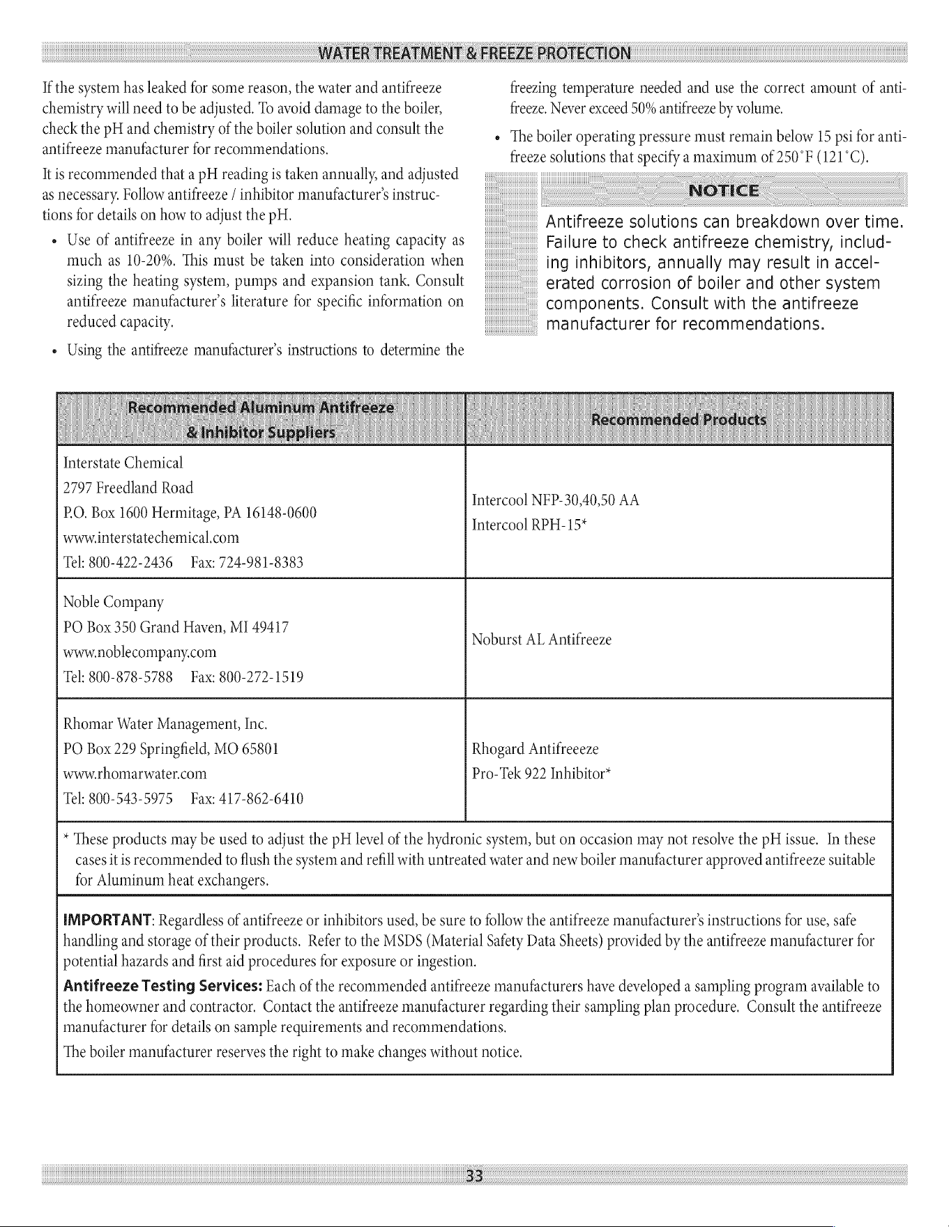
WATER
TREATMENT
&
FREEZE
PROTECTION
If
the
system
has
leaked
for
some
reason,
the
water
and
antifreeze
chemistry
will
need
to
be
adjusted.
To
avoid
damage
to
the
boiler,
check
the
pH
and
chemistry
of
the
boiler
solution
and
consult
the
antifreeze
manufacturer
for
recommendations.
It
is
recommended
that
a
pH
reading
is
taken
annually,
and
adjusted
as
necessary.
Follow
antifreeze
/
inhibitor
manufacturer's
instruc-
tions
for
details
on
how
to
adjust
the
pH.
«
Use
of
antifreeze
in
any
boiler
will
reduce
heating
capacity
as
much
as
10-20%.
This
must
be
taken
into
consideration
when
sizing
the
heating
system,
pumps
and
expansion
tank.
Consult
antifreeze
manufacturer's
literature
for
specific
information
on
reduced
capacity.
¢
Using
the
antifreeze
manufacturer’s
instructions
to
determine
the
freezing
temperature
needed
and
use
the
correct
amount
of
anti-
freeze.
Never
exceed
50%
antifreeze
by
volume.
¢
The
boiler
operating
pressure
must
remain
below
15
psi
for
anti-
freeze
solutions
that
specify
a
maximum
of
250°F
(121°C).
NOTICE
Antifreeze
solutions
can
breakdown
over
time.
Failure
to
check
antifreeze
chemistry,
includ-
ing
inhibitors,
annually
may
result
in
accel-
erated
corrosion
of
boiler
and
other
system
components.
Consult
with
the
antifreeze
manufacturer
for
recommendations.
Interstate
Chemical
2797
Freedland
Road
P.O.
Box
1600
Hermitage,
PA
16148-0600
www.interstatechemical.com
Tel:
800-422-2436
Fax:
724-981-8383
Intercool
NFP-30,40,50
AA
Intercool
RPH-15*
Noble
Company
PO
Box
350
Grand
Haven,
MI
49417
www.noblecompany.com
Tel:
800-878-5788
Fax:
800-272-1519
Noburst
AL
Antifreeze
Rhomar
Water
Management,
Inc.
PO
Box
229
Springfield,
MO
65801
www.thomarwater.com
Tel:
800-543-5975
Fax:
417-862-6410
Rhogard
Antifreeeze
Pro-Tek
922
Inhibitor*
for
Aluminum
heat
exchangers.
*
These
products
may
be
used
to
adjust
the
pH
level
of
the
hydronic
system,
but
on
occasion
may
not
resolve
the
pH
issue.
In
these
cases
it
is
recommended
to
flush
the
system
and
refill
with
untreated
water
and
new
boiler
manufacturer
approved
antifreeze
suitable
IMPORTANT:
Regardless
of
antifreeze
or
inhibitors
used,
be
sure
to
follow
the
antifreeze
manufacturer's
instructions
for
use,
safe
handling
and
storage
of
their
products.
Refer
to
the
MSDS
(Material
Safety
Data
Sheets)
provided
by
the
antifreeze
manufacturer
for
potential
hazards
and
first
aid
procedures
for
exposure
or
ingestion.
Antifreeze
Testing
Services:
Each
of
the
recommended
antifreeze
manufacturers
have
developed
a
sampling
program
available
to
the
homeowner
and
contractor.
Contact
the
antifreeze
manufacturer
regarding
their
sampling
plan
procedure.
Consult
the
antifreeze
manufacturer
for
details
on
sample
requirements
and
recommendations.
The
boiler
manufacturer
reserves
the
right
to
make
changes
without
notice.
33
START
UP
Filling
Boiler
With
Water
And
Purging
Air
For
Systems
With
Diaphragm
Type
Expansion
Tanks
Refer
to
the
appropriate
diagrams
in
Section
VII,
“Near
Boiler
Pip-
ing,’ for
more
information.
1.
Close
all
zone
service
valves
on
the
supply
and
return
piping.
Open
the
feed
valve
and
fill
boiler
with
water.
Make
sure
air
vent
is
open.
Hold
relief
valve
open
until
water
runs
air
free
for
five
seconds
to
rapidly
bleed
air
from
boiler,
then
let
the
relief
valve
snap
shut.
2.
Open
the
zone
service
valve
on
the
supply
pipe
for
the
first
zone.
Open
the
purge
valve
on
the
first
zone.
Feed
water
will
fill
the
zone,
pushing
air
out
the
purge
valve.
Close
the
purge
valve
when
the
water
runs
air
free.
Close
the
zone
service
valve.
3.
Repeat
step
2
for
all
remaining
zones.
4.
Open
all
service
valves.
Any
air
remaining
trapped
in
the
return
lines
between
the
service
valves
and
the
boiler
will
be
pushed
towards
the
air
vent
when
the
boiler
is
placed
in
operation.
5.
Inspect
piping
system.
Repair
any
leaks
immediately.
Purging
Air
For
Systems
With
Conventional
Closed
Type
Expansion
Tanks:
Refer
to
the
appropriate
diagrams
in
Section
VII,
“Near
Boiler
Piping,
for
more
information.
1.
Close
all
zone
service
valves
on
the
supply
and
return
piping
and
close
the
expansion
tank
service
valve.
Drain
expansion
tank.
Open
the
feed
valve
and
fill
boiler
with
water.
Hold
relief
valve
open
until
water
runs
air
free
for
five
seconds
to
rapidly
bleed
air
from
boiler,
then
let
the
relief
valve
snap
shut.
2.
Open
the
zone
service
valve
on
the
supply
pipe
for
the
first
zone.
Open
the
purge
valve
on
the
first
zone.
Feed
water
will
fill
the
zone,
pushing
air
out
the
purge
valve.
Close
the
purge
valve
when
the
water
runs
air
free.
Close
the
zone
service
valve.
3.
Repeat
step
2
for
all
remaining
zones.
4.
Open
the
expansion
tank
service
valve
and
the
tank
vent.
Fill
the
tank
to
the
proper
level
and
close
the
tank
vent.
Remove
the
handle
from
the
expansion
tank
service
valve
so
the
homeowner
doesn’t
accidentally
close
it.
5.
Open
all
service
valves.
Any
air
remaining
trapped
in
the
return
lines
between
the
service
valves
and
the
boiler
will
be
pushed
towards
the
expansion
tank
when
the
boiler
is
placed
in
opera-
tion.
6.
Inspect
piping
system.
Repair
any
leaks
immediately.
NOTICE
DO
NOT
use
stop
leak
compounds.
Leaks
in
threaded
connections
in
the
aluminum
boiler
sections
must
be
repaired
immediately.
Aluminum
threads
will
not
seal
themselves.
Placing
Boiler
In
Operation
WARNING
If
you
do
not
follow
these
instructions
exactly,
a
fire
or
explosion
may
result
causing property
damage,
personal
injury
or
loss
of
life.
This
appliance
is
equipped
with
an
ignition
device
which
automatically
lights
the
pilot.
Do
not
try
to
light
the
pilot
by
hand.
BEFORE
OPERATING
smell
all
around
the
appliance
area
for
gas.
Be
sure
to
smell
next
to
the
floor
because
some
gas
is
heavier
than
air
and
will
settle
on
the
floor.
What
To
Do
If
You
Smell
Gas
«Do
not
try
to
light
any
appliance.
«Do
not
touch
any
electrical
switch;
do
not
use
any
phone
in
your
building.
«Immediately
call
your
gas
supplier
from
a
neighbor's
phone.
Follow
the gas
supplier's
instructions.
eIf
you
cannot
reach
your
gas
supplier,
call
the
fire
depart-
ment.
Use
only
your
hand
to
move
the
system
control
switch.
Never
use
tools.
If
the
switch
will
not
move
by
hand,
don’t
try
to
repair
it,
call
a
qualified
service
technician.
Force
or
attempted
repair
may
result
in
a
fire
or
explosion.
Do
not
use
this
appliance
if
any
part
has
been
under
water.
Immediately
call
a
qualified
service
technician
to
inspect
the
appliance
and
to
replace
any
part
of
the
control
system
and
any
gas
control
which
has
been
under
water.
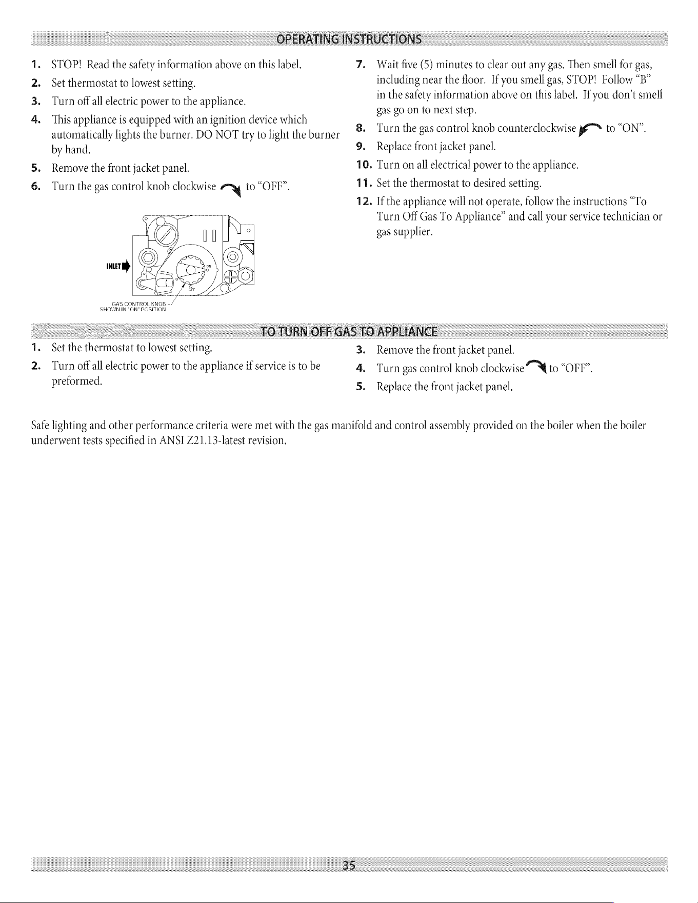
OPERATING
INSTRUCTIONS
1.
STOP!
Read
the
safety
information
above
on
this
label.
7.
Wait
five
(5)
minutes
to
clear
out
any
gas.
Then
smell
for
gas,
2.
Set
thermostat
to
lowest
setting.
including
near
the
floor.
If
you
smell
gas,
STOP!
Follow
“B”
3.
Turn
offall electric
power
to
the
appliance
in
the
safety
information
above
on
this
label.
If
you
don’t smell
1.
Str
p
dwith
PP
i
device
which
gas
go
on
to
next
step.
.
This
appliance
is
equipped
with
an
ignition
device
whic
ean
automatically
lights
the
burner.
DO
NOT
try
to
light
the
burner
Turn
the
gas
control
knob
counterclockwise
y™~
to
“ON”.
by
hand.
9.
Replace
front
jacket
panel.
5.
Remove
the
front
jacket
panel.
10.
Turn
on
all
electrical
power
to
the
appliance.
6.
Turn
the gas
control
knob
clockwise
ry
fo
“OFF”.
11.
Set
the
thermostat
to
desired
setting.
12.
If
the
appliance
will
not
operate,
follow
the
instructions
“To
Turn
Off
Gas
To
Appliance”
and
call
your
service
technician
or
gas
supplier.
TOTURN
OFF
GAS
TO
APPLIANCE
1.
Set
the
thermostat
to
lowest
setting.
3.
Remove
the
front
jacket
panel.
2.
Turn
off
all
electric
power
to
the
appliance
if
service
is
to
be
4.
Turn
gas
control
knob
clockwise
to
“OFP”.
preformed.
5.
Replace
the
front
jacket panel.
Safe
lighting
and
other
performance
criteria
were
met
with
the gas
manifold
and
control
assembly
provided
on
the
boiler
when
the
boiler
underwent
tests
specified
in
ANSI
Z21.13-latest
revision.
35
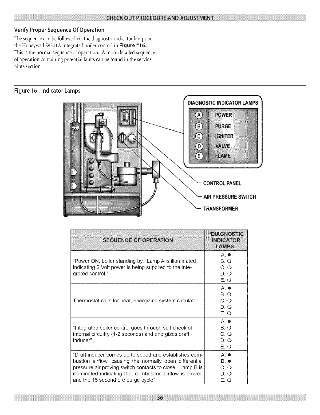
CHECK
OUT
PROCEDURE
AND
ADJUSTMENT
Verify
Proper
Sequence
Of
Operation
The
sequence
can
be
followed
via
the
diagnostic
indicator
lamps
on
the
Honeywell
$9301A
integrated
boiler
control
in
Figure
#16.
This
is
the
normal
sequence
of
operation.
A
more
detailed
sequence
of
operation
containing
potential
faults
can
be
found
in
the
service
hints
section.
Figure
16
-
Indicator
Lamps
( \
DIAGNOSTIC
INDICATOR
LAMPS
CONTROL
PANEL
AIR
PRESSURE
SWITCH
TRANSFORMER
“DIAGNOSTIC
SEQUENCE
OF
OPERATION
INDICATOR
LANIPS”
A.
@
“Power
ON,
boiler
standing
by.
Lamp
Ais
illuminated
B.O
indicating
2
Volt
power
is
being
supplied
to
the
inte-
Cc.O
grated
control.”
D.O
E.O
A.
@
B.O
Thermostat
calls
for
heat,
energizing
system
circulator
Cc.O
D.O
E.O
A.
@
“Integrated
boiler
control
goes
through
self
check
of
B.O
internal
circuitry
(1-2
seconds)
and
energizes
draft
Cc.O
inducer”
D.O
E.O
“Draft
inducer
comes
up
to
speed
and
establishes
com-
A.
@
bustion
airflow,
causing
the
normally
open
differential
B.
@
pressure
air
proving
switch
contacts
to
close.
Lamp
Bis
Cc.O
illuminated
indicating
that
combustion
airflow
is
proved
D.O
and
the
15
second
pre
purge
cycle”
E.O
36
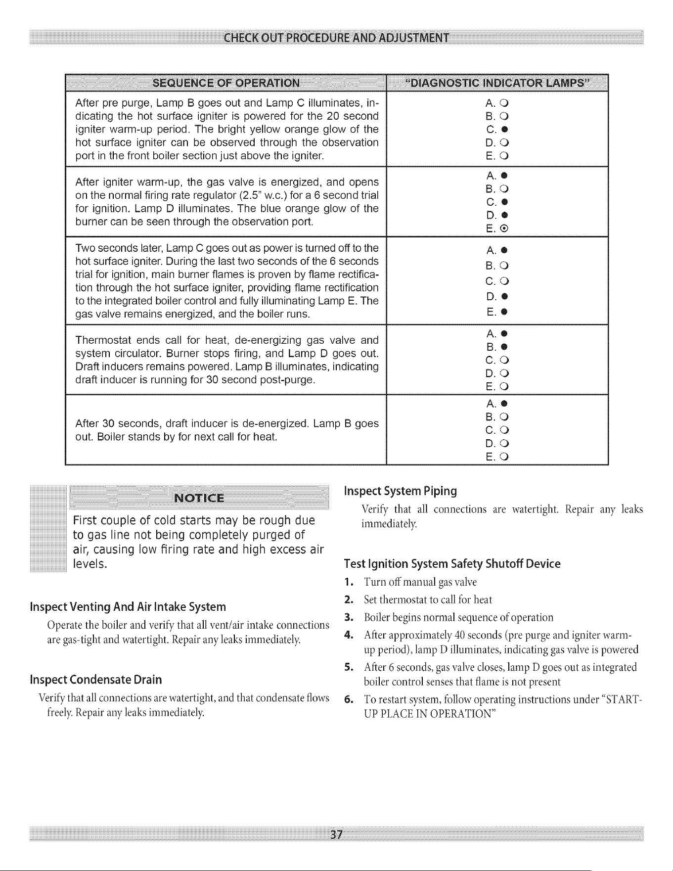
CHECK
OUT
PROCEDURE
AND
ADJUSTMENT
SEQUENCE
OF
OPERATION
“DIAGNOSTIC
INDICATOR
LAMPS”
After
pre
purge,
Lamp
B
goes
out
and
Lamp
C
illuminates,
in-
dicating
the
hot
surface
igniter
is
powered
for
the
20
second
igniter
warm-up
period.
The
bright
yellow
orange
glow
of
the
hot
surface
igniter
can
be
observed
through
the
observation
port
in
the
front
boiler
section
just
above
the
igniter.
After
igniter
warm-up,
the
gas
valve
is
energized,
and
opens
on
the
normal
firing
rate
regulator
(2.5”
w.c.)
for
a 6
second
trial
for
ignition.
Lamp
D
illuminates.
The
blue
orange
glow
of
the
burner
can
be
seen
through
the
observation
port.
Two
seconds
later,
Lamp
C
goes
out
as
power
is
turned
off
to
the
hot
surface
igniter.
During
the
last
two
seconds
of
the
6
seconds
trial
for
ignition,
main
burner
flames
is
proven
by
flame
rectifica-
tion
through
the hot
surface
igniter,
providing
flame
rectification
to
the
integrated
boiler
control
and
fully
illuminating
Lamp
E.
The
gas
valve
remains
energized,
and
the
boiler
runs.
Thermostat
ends
call
for
heat,
de-energizing
gas
valve
and
system
circulator.
Burner
stops
firing,
and
Lamp
D
goes
out.
Draft
inducers
remains
powered.
Lamp
B
illuminates,
indicating
draft
inducer
is
running
for
30
second
post-purge.
After
30
seconds,
draft
inducer
is
de-energized.
Lamp
B
goes
out.
Boiler
stands
by
for
next
call
for
heat.
MOODr
MIOOmMr
MmoOOWDr
MmOODp
MOODY
COCOCe/OOCCee@|
@eOCOOelOe@e@eOe@e
OCe0O
NOTICE
First
couple
of
cold
starts
may
be
rough
due
to
gas
line
not
being
completely
purged
of
air,
causing
low
firing
rate
and
high
excess
air
levels.
Inspect
Venting
And
Air
Intake
System
Operate
the
boiler
and
verify
that
all
vent/air
intake
connections
are
gas-tight
and
watertight.
Repair
any
leaks
immediately.
Inspect
Condensate
Drain
Verify
that
all
connections
are
watertight, and
that
condensate
flows
freely.
Repair
any
leaks
immediately.
3/
Inspect
System
Piping
Verify
that
all
connections
are
watertight.
Repair
any
leaks
immediately.
Test
Ignition
System
Safety
Shutoff
Device
1.
Turn
off
manual
gas
valve
Set
thermostat
to
call
for
heat
Boiler
begins
normal
sequence
of
operation
PWN
After
approximately
40
seconds
(pre
purge
and
igniter
warm-
up
period),
lamp
D
illuminates,
indicating
gas
valve
is
powered
5.
After
6
seconds,
gas
valve
closes,
lamp
D
goes
out
as
integrated
boiler
control
senses
that
flame
is
not
present
6.
To
restart
system,
follow
operating
instructions
under
“START-
UP
PLACE
IN
OPERATION”
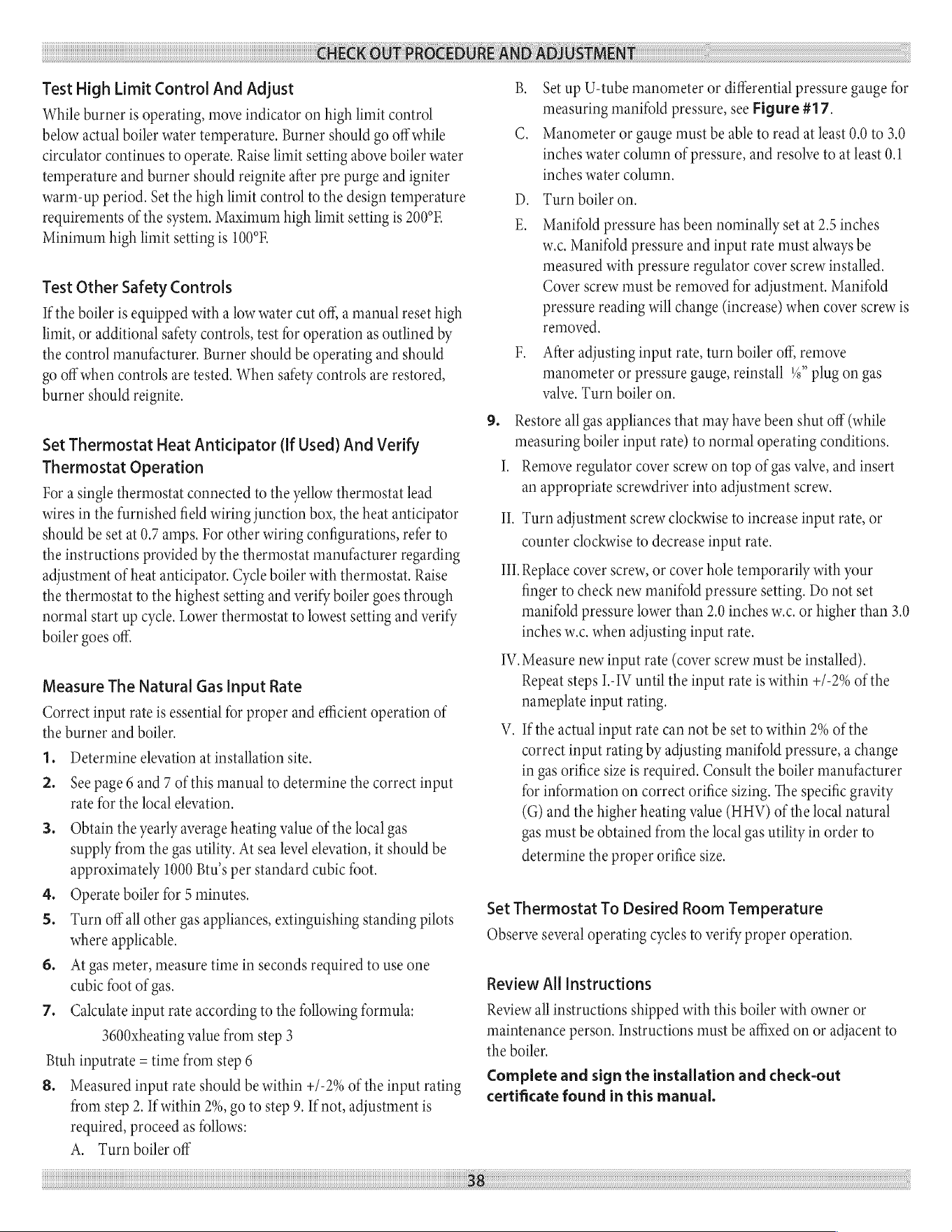
CHECK
OUT
PROCEDURE
AND
ADJUSTMENT
Test
High
Limit
Control
And
Adjust
While
burner
is
operating,
move
indicator
on
high
limit
control
below
actual
boiler
water
temperature.
Burner
should
go
off
while
circulator
continues
to
operate.
Raise
limit
setting
above
boiler
water
temperature
and
burner
should
reignite
after
pre
purge
and
igniter
warm-up
period.
Set
the
high
limit
control
to
the
design
temperature
requirements
of
the
system.
Maximum
high
limit
setting
is
200°F.
Minimum
high
limit
setting
is
100°F.
Test
Other
Safety
Controls
If
the
boiler
is
equipped
with
a
low
water
cut
off,
a
manual
reset
high
limit,
or
additional
safety
controls,
test
for
operation
as
outlined
by
the
control
manufacturer.
Burner
should
be
operating
and
should
go
off
when
controls
are
tested.
When
safety
controls
are
restored,
burner
should
reignite.
Set
Thermostat
Heat
Anticipator
(If
Used)
And
Verify
Thermostat
Operation
For
a
single
thermostat
connected
to
the
yellow
thermostat
lead
wires
in
the
furnished
field
wiring
junction
box,
the
heat
anticipator
should
be
set
at
0.7
amps.
For
other
wiring
configurations,
refer
to
the
instructions
provided
by
the
thermostat
manufacturer
regarding
adjustment
of
heat
anticipator.
Cycle
boiler
with
thermostat.
Raise
the
thermostat
to
the
highest
setting
and
verify
boiler
goes
through
normal
start
up
cycle.
Lower
thermostat
to
lowest
setting
and
verify
boiler
goes
off.
Measure
The
Natural
Gas Input
Rate
Correct
input
rate
is
essential
for
proper
and
efficient
operation
of
the
burner
and
boiler.
1.
2.
Determine
elevation
at
installation
site.
See
page
6
and
7
of
this
manual
to
determine
the
correct
input
rate
for
the
local
elevation.
Obtain
the
yearly
average heating
value
of
the
local
gas
supply
from
the gas
utility.
At
sea
level
elevation,
it
should
be
approximately
1000
Btu’s
per
standard
cubic
foot.
Operate
boiler
for
5
minutes.
Turn
off
all
other
gas
appliances,
extinguishing
standing
pilots
where
applicable.
At
gas
meter,
measure
time
in
seconds
required
to
use
one
cubic
foot
of
gas.
Calculate
input
rate
according
to
the
following
formula:
3600xheating
value
from
step
3
Btuh
inputrate
=
time
from
step
6
8.
Measured
input
rate
should
be
within
+/-2%
of
the
input
rating
from
step
2.
If
within
2%,
go
to
step
9.
If
not,
adjustment
is
required,
proceed
as
follows:
A.
Turn
boiler
off
38
B.
Set
up
U-tube
manometer
or
differential
pressure
gauge
for
measuring
manifold
pressure,
see
Figure
#17.
C.
Manometer
or
gauge
must
be
able
to
read
at
least
0.0
to
3.0
inches
water
column
of
pressure,
and
resolve
to
at
least
0.1
inches
water
column.
Turn
boiler
on.
Manifold
pressure
has
been
nominally
set
at
2.5
inches
w.c.
Manifold
pressure
and
input
rate
must
always
be
measured
with
pressure
regulator
cover
screw
installed.
Cover
screw
must
be
removed
for
adjustment.
Manifold
pressure
reading
will
change
(increase)
when
cover
screw
is
removed.
After
adjusting
input
rate,
turn
boiler
off,
remove
manometer
or
pressure
gauge,
reinstall
%”
plug
on
gas
valve,
Turn
boiler
on.
Restore
all
gas
appliances
that
may
have
been
shut
off
(while
measuring
boiler
input
rate)
to
normal
operating
conditions.
I.
Remove
regulator
cover
screw
on
top
of
gas
valve,
and
insert
an
appropriate
screwdriver
into
adjustment
screw.
II,
Turn
adjustment
screw
clockwise
to
increase
input
rate,
or
counter
clockwise
to
decrease
input
rate.
Il].
Replace
cover
screw,
or
cover
hole
temporarily
with
your
finger
to
check
new
manifold
pressure
setting.
Do
not
set
manifold
pressure
lower
than
2.0
inches
w.c.
or
higher
than
3.0
inches
w.c.
when
adjusting
input
rate.
IV.
Measure
new
input
rate
(cover
screw
must
be
installed).
Repeat
steps
I-IV
until
the
input
rate
is
within
+/-2%
of
the
nameplate
input
rating.
V.
If
the
actual
input
rate
can not
be
set
to
within
2%
of
the
correct
input
rating
by
adjusting
manifold
pressure,
a
change
in
gas
orifice
size
is
required.
Consult
the
boiler
manufacturer
for
information
on
correct
orifice
sizing.
The
specific
gravity
(G)
and
the
higher
heating
value
(HHV)
of
the
local
natural
gas
must
be
obtained
from
the
local
gas
utility
in
order
to
determine
the
proper
orifice
size.
Set
Thermostat
To
Desired
Room
Temperature
Observe
several
operating
cycles
to
verify
proper
operation.
Review
All
Instructions
Review
all
instructions
shipped
with
this
boiler
with
owner
or
maintenance
person.
Instructions
must
be
affixed
on
or
adjacent
to
the
boiler.
Complete
and
sign
the
installation
and
check-out
certificate
found
in
this
manual.
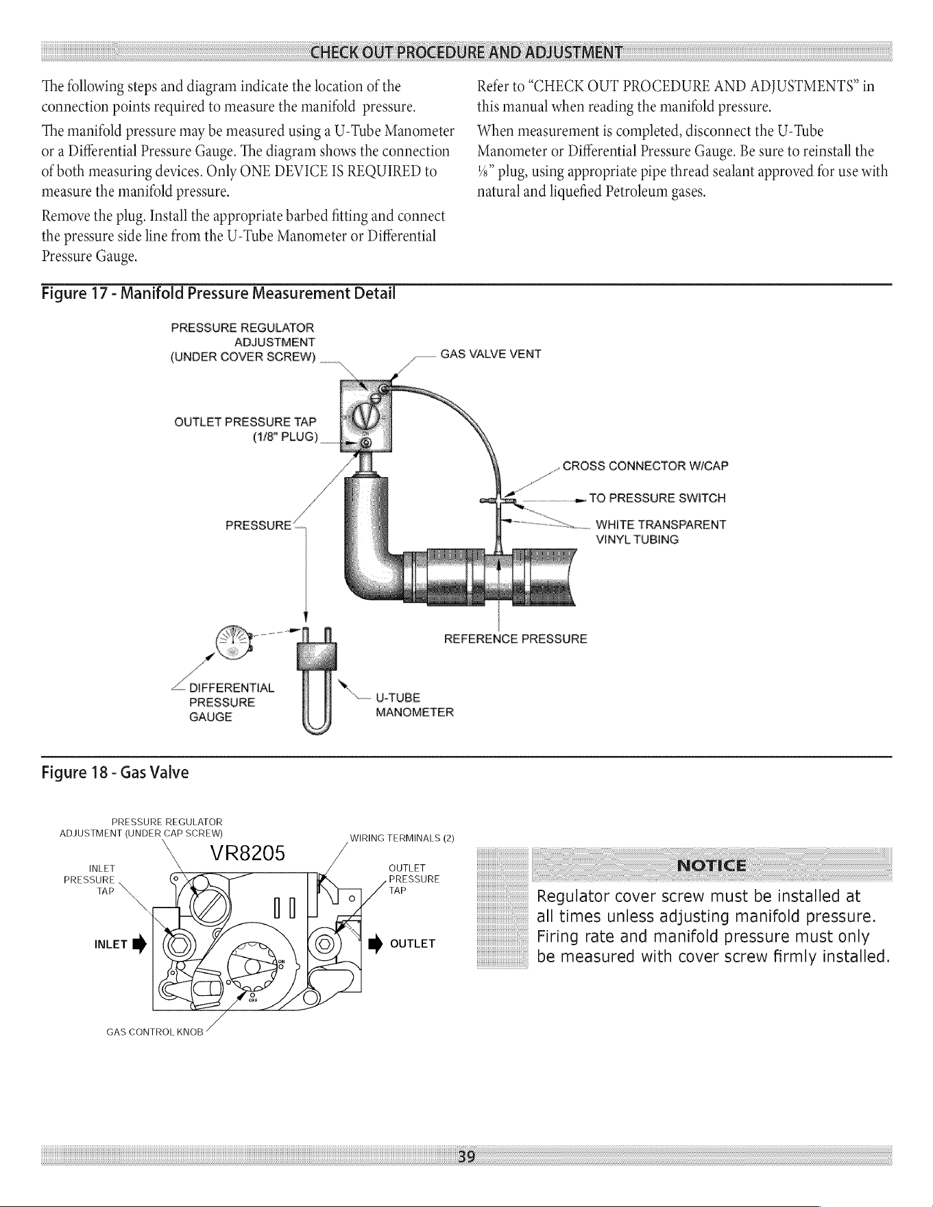
CHECK
OUT
PROCEDURE
AND
ADJUSTMENT
The
following
steps
and
diagram
indicate
the
location
of
the
connection
points
required
to
measure
the
manifold
pressure.
The
manifold
pressure
may
be
measured
using
a
U-Tube
Manometer
or
a
Differential
Pressure
Gauge.
The
diagram
shows
the
connection
of
both
measuring
devices.
Only
ONE
DEVICE
IS
REQUIRED
to
measure
the
manifold
pressure.
Remove
the
plug.
Install
the
appropriate
barbed
fitting
and
connect
the
pressure
side
line
from
the
U-Tube
Manometer
or
Differential
Pressure
Gauge.
Refer
to
“CHECK
OUT
PROCEDURE
AND
ADJUSTMENTS?
in
this
manual
when
reading
the
manifold
pressure.
When
measurement
is
completed, disconnect
the
U-Tube
Manometer
or
Differential
Pressure
Gauge.
Be sure
to
reinstall
the
¥4”
plug,
using
appropriate
pipe
thread
sealant
approved
for
use
with
natural
and
liquefied
Petroleum
gases.
Figure
17
-
Manifold
Pressure
Measurement
Detail
PRESSURE
REGULATOR
ADJUSTMENT
(UNDER
COVER
SCREW)
vw
OUTLET
PRESSURE
TAP
(1/8"
PLUG)
_-—
GAS VALVE
VENT
_-
GROSS
CONNECTOR
W/CAP
AB
Bo
J —..»
TO
PRESSURE
SWITCH
v
PRESSURE,
Sine...
WHITE
TRANSPARENT
/
VINYL
TUBING
/
Cy
ee
REFERENCE
PRESSURE
el
oo
<.
DIFFERENTIAL
PRESSURE
U-TUBE
GAUGE
MANOMETER
Figure
18
-
Gas
Valve
PRESSURE
REGULATOR
ADJUSTMENT
(UNDER
CAP
SCREW)
WIRING
TERMINALS
(2)
VR8205
INLET
OUTLET
NOTICE
PRESSURE
PRESSURE
TAP
TAP
INLET
»
»
OUTLET
GAS
CONTROL
KNOB
39
Regulator
cover
screw
must
be
installed
at
all
times
unless
adjusting
manifold
pressure.
Firing
rate
and
manifold
pressure
must
only
be
measured
with
cover
screw
firmly
installed.
INSTALLATION
AND
CHECK-OUT
CERTIFICATE
40
au
nl
|
aa
INSTALLATION
AND
CHECK-OUT
CERTIFICATE
Boiler
Model
Serial
#
Date
Installed
Measured
BTU/HR
input
©
Installation
instructions
have
been
followed
©
Checkout
procedure
and
adjustments
performed
O
Maintenance
and
Service
issues
reviewed
with
owner/
maintenance
person
©
Installation
booklet
affixed
on
or
adjacent
to
boiler
installer
(Company)
Address
Phone
installer’s
Name
Signature
—
poe.
EN
io
MAINTENANCE
AND
CLEANING
Maintenance
as
outlined
below
can
be
performed
by
the
2.
owner
unless
otherwise
noted.
The
acidic
nature
of
flue
gasses
condensing
on
the
aluminum
boiler
—3.
sections
will
cause
the
formation
of
aluminum
oxide.
This
oxide
formation
is
normal,
is
generally
uniform
throughout
the
boiler
sections,
and
represents
a
negligible
mass
of
aluminum
that
is
consumed
by
oxidation
during
the
life
of
the
boiler.
If
left
unchecked,
this
buildup
may
eventually
cause
blockage
of
the
flue
gas
passages
in
the
boiler
sections,
reducing
efficiency,
and
ultimately
shutting
down
the
boiler
due
to
lack
of
combustion
air
flow.
Regular
service
and
maintenance
by
a
qualified
service
agency
must
be
performed
to
2.
Beginning
Of
Each
Heating
Season
1.
Annual
service
call
by
a
qualified
service
agency,
which
includes:
A.
Examine
flue
passages
between
boiler
sections,
burner,
and
condensate
lines,
and
clean
if
necessary
following
the
annual
examination
and
cleaning
instructions
in
para
graph
“F”
on
the
next
page.
B.
Visually
inspect
venting
and
air
intake
system
for
proper
function,
deterioration
or
leakage.
If
the
vent
or
air
intake
show
any
signs
of
deterioration
or
leakage,
repair
or
replace
them,
immediately.
Insure
proper
reassembly
and
resealing
of
the
vent
and
air
intake
system
C.
Check
for
and
remove
any
obstruction
to
the
flow
of
combustion
air
or
venting
of
flue
gases.
Check
the
air
baffle
located
inside
112”
x
2”
flexible
coupling
on
the
mixer,
clean
it
if
necessary
and
make
sure
to
put
it
back.
Refer
to
repair
parts
diagram
of
mixer
and
pressure
switch
assembly
for
exact
location.
D.
Follow
instructions
for
“PLACING
BOILER
IN
OPERATION”.
E.
Follow
instructions
for?
CHECK
OUT
PROCEDURE
AND
ADJUSTMENTS”,
F.
Visually
inspect
condensate
drain
line
for
proper
operation
and
deterioration.
Check
for
plugged
condensate
drain
line.
G.
Check
the
silicone
rubber
seals
between
boiler
sections.
Insure
that
there
are
no
leaks.
Use
RTV
silicone
rubber
adhesive
sealant (available
in
caulking
gun
tubes)
rated
for
at
least
400°
F
to
replace
or
repair
seals
in
locations
where
original
seals
have
deteriorated,
H.
Check
all
gasketed
joints
for
leakage,
and
tighten
bolts
or
replace
gaskets
if
necessary.
I.
Remove
jacket
front
and
top
panels
and
check
for
piping
leaks
around
relief
valve
and
other
fittings.
Repair,
if
found.
DO
NOT
use
stop
leak
compounds.
4)
Check
that
boiler
area
is
free
from
combustible
materials,
gasoline,
and
other
flammable
vapors
and
liquids.
Circulator
pump
and
blower
motor
furnished
with
boiler
are
permanently
lubricated
from
factory
and require
no
further
lubrication.
Additional
or
non-factory
supplied
pumps
and/
or
motors
should
be
lubricated
according
to
the
pump
and/or
motor
manufacturer’s
instruction.
Daily
During
Heating
Season
assure
safe
trouble
free
operation
and
maximum
efficiency.
1.
Check
for
and
remove
any
obstruction
to
the
flow
of
combustion
air
or
venting
of
flue
gases.
Check
that
boiler
area
is
free
from
combustible
materials,
gasoline,
and
other
flammable
vapors
and
liquids.
MAINTENANCE
AND
CLEANING
Monthly
During
Heating
Season
1.
1.
Remove
jacket
front
and
top
panels
and
check
for
piping
leaks
around
relief
valve
and
other
fittings.
If
found,
contact
a
qualified
service
agency
to
repair.
DO
NOT
use
stop
leak
compounds.
2.
Test
relief
valve.
Refer
to
valve
manufacturers
instructions
packaged
with
relief
valve.
3.
Visually
inspect
venting
and
air
intake
system
for
proper
function,
deterioration,
or
leakage.
If
the
vent
or
air
intake
show
any
signs
of
deterioration
or
leakage,
contact
a
qualified
service
agency
to
repair
or
replace
them
immediately
and
to
insure
proper
reassembly
and
resealing
of
the
vent
and
air
intake
system.
4,
Visually
inspect
the
clear
vinyl
condensate
lines
and
the
PVC
condensate
drain
pipe
for
proper
operation,
leakage,
and
deterioration.
If
the
condensate
lines
or
drain
pipe
show
any
signs
of
blockage,
leakage,
or
deterioration
contact
a
qualified
service
agency
to
clean,
repair,
or
replace
them
immediately.
5,
Check
the
air
baffle
located
inside
1
4”
x
2”
flexible
coupling,
clean
it
if
necessary
and
make
sure
to
put
it
back.
Refer
to
repair
parts
diagram,
mixer
and
pressure
switch
assembly.
Periodically
During
Heating
Season
Where
low
water
cut
offs
are
used,
a
periodic
inspection
of
the
low
water
cut
off
is
necessary,
including
flushing
of float
type
devices.
Refer
to
low
water
cut
off
manufacturer's
specific
instructions.
End
of
Each
Heating
Season
-
Annual
Shutdown
Procedure
Follow
instructions
“TO
TURN
OFF
GAS
TO
APPLIANCE”
If
heating
system
is
to
remain
out
of
service
during
freezing
weather,
and
does
not
contain
antifreeze,
drain
system
completely.
If
boiler
will be
exposed
to
freezing
temperatures,
drain
condensate
lines.
Otherwise,
do
not
drain
system
or
boiler.
Annual
Examination
And
Cleaning
Of
Boiler
Components
1.
Before
Servicing,
turn
off
electrical
power
to
boiler
at
service
switch.
Close
manual
gas
valve
to
turn
off
gas
supply
to
boiler.
42
NOTICE
The
following
service
procedures
must
be
performed
only
by
a
qualified
service
agency.
Boiler
owner
should
not
attempt
these
procedures.
Cleaning
Flue
passages
between
boiler
sections.
A.
O
Any
buildup
of
sediment
or
aluminum
oxide
(white
powdery
or
flaky
substance)
in
the
flue
passages
must
be
cleaned
as
follows:
Remove
jacket
front
and
top
panels.
Disconnect
condensate
drain
line
from
the
barbed
fitting
on
the
bottom
of
the
boiler.
Keep
the
open
end
of
the
drain
line
above
the
water
level
in
the
condensate
trap
to
prevent
the
trap
from
draining.
Disconnect
pressure
switch
hose
from
barbed
fitting
on
gas
valve.
Disconnect
1%
x
2”
flexible
coupling
from
air
inlet.
Disconnect
air
by-pass
(4”
transparent
vinyl
tube)
from
the
bottom
of
the
mixer.
Remove
air
baffle
from
%”
x
2”
flexible
coupling
and
clean
air
baffle
if
necessary.
Refer
to
repair
parts
diagram,
mixer
and
pressure
switch
assembly.
Confirm
that
manual
gas
valve
is
closed
and
disconnect
gas
line
to
gas
valve
at
union,
Disconnect
wires
to
gas
valve.
and
igniter,
Loosen
but
do
not
remove
five
(5)
nuts
attaching
mixer
assembly
to
boiler.
Remove
two
(2)
igniter
screws
and
very
carefully
remove
the
igniter.
Use
care
when
removing
the
igniter,
it
is
very
brittle!
Remove
five
(5)
nuts
and
remove
mixer
assembly.
Remove
burner
and
mixer
gasket.
Aluminum
oxide
deposits
are
water
soluble
and
may
be
rinsed
away
with
spraying
or
running
water.
Before
rinsing,
connect
a
%”
ID,
hose
to
the
barbed
fitting
on
the
bottom
of
the
boiler
and
run
the
hose
to
a
bucket
or
drain.
After
rinsing,
remove
any
remaining
loosened
sediment
using
a
shop
vacuum
with
a
snorkel
attachment.
Inspect
burner
for
any
foreign
matter
in
the
flame
ports
or
inside
the
burner.
Any
foreign
matter
should
be
removed
by
blowing
with
compressed
air
or
vacuuming.
Inspect
interior
of
mixer
for
any
signs
of
sediment
or
aluminum
oxide
and
clean
if
necessary.
MAINTENANCE
AND
CLEANING
K.
Reinstall
burner
and
mixer
gasket
and
position
mixer
L.
assembly
over
studs.
Install
five
(5)
nuts
but
do
not
tighten.
Reinstall
igniter
and
igniter
gasket
and
fasten
with
two
(2)
screws.
Use
care
when
installing
the
igniter.
It is
very
brittle!
Tighten
five
(5)
nuts
holding
mixer
assembly.
Connect:
¢Gas
line
to
gas
valve
«Condensate
drain
line
to
boiler
«Pressure
switch
hose
to
gas
valve
«Air
by-pass
to
mixer
1
%”
x2”
flexible
coupling
to
air
inlet
and
make
sure
to
put
air
baffle
back
to
correct
position
«Igniter
wires
Gas
valve
wires
3.
Visually
inspect
condensate
lines
leading
from
the
boiler
sections
and
the
vent
tee
to
the
condensate
trap.
Refer
to
repair
parts
diagrams.
Any
foreign
material
or
debris
that
is
visible
in
the
condensate
lines
needs
to
be
cleaned
out
as
follows:
A.
Raise
condensate
trap
and
drain
condensate
lines
B,
completely.
Once
the
condensate
trap
is
emptied
of
water,
disconnect
condensate
lines
from
the
fittings
on
the
boiler,
the
vent
tee,
and
the
condensate
outlet.
Remove
the
condensate
trap
and
run
cold
water
through
the
condensate
lines
to
thoroughly
flush
out
any
sediment
or
debris
in
the
lines.
Reinstall
and
connect
the
condensate
trap,
using
the
hose
clamps
to
secure
the
various
condensate
lines
to
their
fittings.
Follow
the
instructions
under
“NEAR
BOILER
PIPING”
for”
filling
condensate
trap
with
water”
43
4,
Inspection
of
the
flue
connector
requires
the
following
steps
(Refer
to
the
repair
parts
diagram.)
A.
Loosen
the
clamp
on
the
draft
inducer
end
of
the
2”
flexible
coupling
that
connects
the
vent
tee
to
the
draft
inducer.
Disconnect
(unplug)
wiring
harness
from
draft
inducer
motor
and
draft
inducer
temperature
safety
switch.
Remove
four
(4)
bolts
that
attach
draft
inducer
to
flue
connector.
Remove
draft
inducer
and
gasket
from
top
of
flue
connector.
Inspect
interior
of
flue
connector.
Any
buildup
of
sediment
or
aluminum
oxide
on
the
inside
surface
must
be
cleaned.
Position
the
draft
inducer
gasket
and
the
draft
inducer
and
fasten
with
four
(4)
screws.
Be
sure
to
connect
ground
wire
from
draft
inducer
motor
to
one
of
the
four
mounting
screws.
Connect
wiring
harness
leads
to
the
draft
inducer
motor
and
the
draft
inducer
temperature
safety
switch.
Connect
the
2”
flexible
coupling
to
the
draft
inducer
outlet.
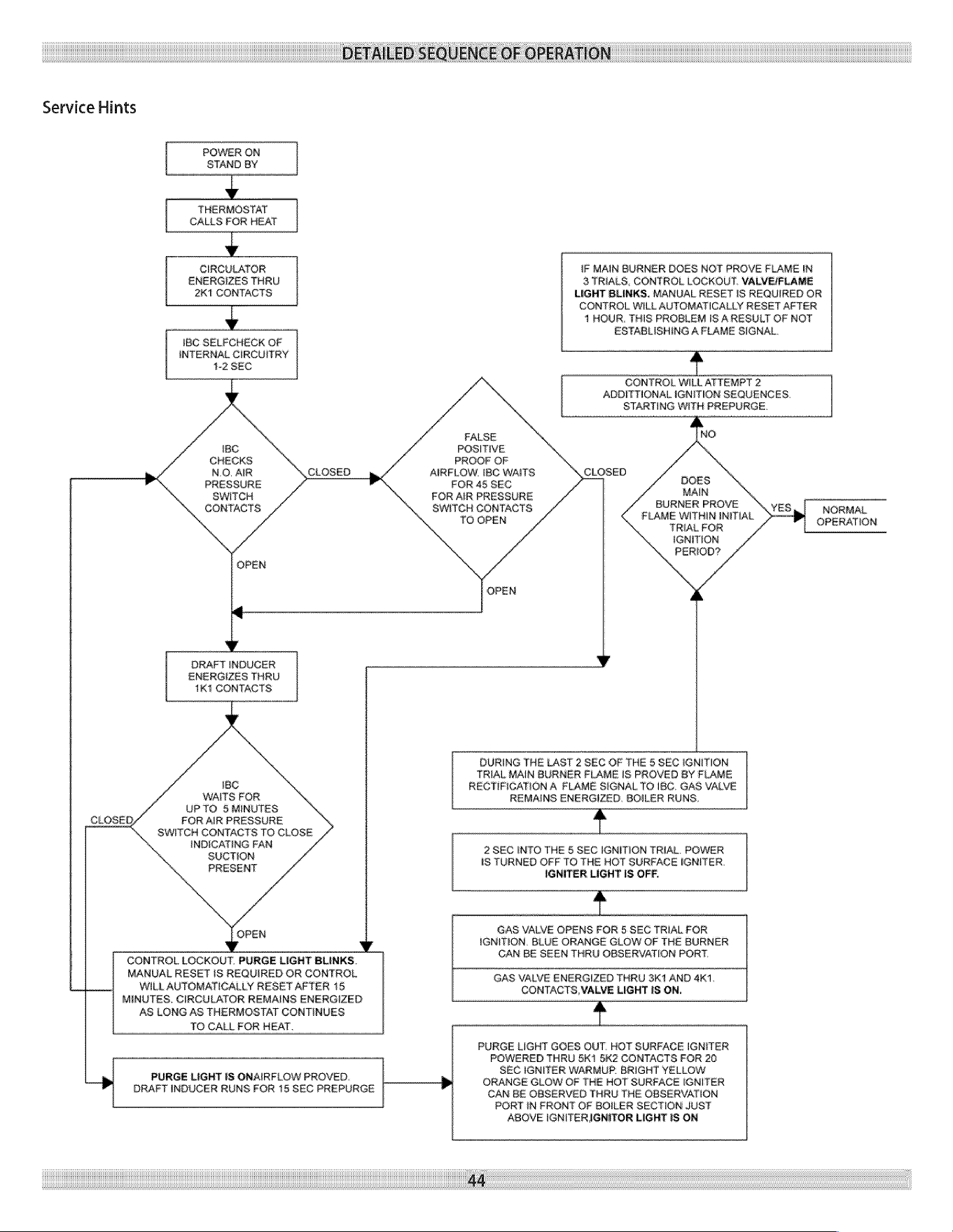
DETAILED
SEQUENCE
OF
OPERATION
Service
Hints
POWER
ON
STAND
BY
y
THERMOSTAT
CALLS
FOR
HEAT
v
CIRCULATOR
ENERGIZES
THRU
2K1
CONTACTS
y
IBC
SELPCHECK
OF
INTERNAL CIRCUITRY
4-2
SEC
IBC
CHECKS
NO.
AIR
PRESSURE
SWITCH
CONTACTS
IF
MAIN
BURNER
DOES
NOT
PROVE
FLAME
IN
3
TRIALS,
CONTROL
LOCKOUT.
VALVE/FLAME
LIGHT
BLINKS.
MANUAL
RESET
IS
REQUIRED
OR
CONTROL
WILL
AUTOMATICALLY
RESET
AFTER
1
HOUR.
THIS
PROBLEM
IS
A
RESULT
OF
NOT
ESTABLISHING
A
FLAME
SIGNAL.
4
CONTROL
WILL
ATTEMPT
2
ADDITTIONAL
IGNITION
SEQUENCES.
STARTING
WITH
PREPURGE.
FALSE
POSITIVE
PROOF
OF
AIRFLOW.
IBC
WAITS
CLOSED
FOR
45
SEC
oN
FOR
AIR
PRESSURE
SWITCH
CONTACTS
_
BURNER
PROVE
NORMAL
TO
OPEN
AA
ato
OPERATION
IGNITION
PERIOD?
DRAFT
INDUCER
ENERGIZES
THRU
1K1
CONTACTS
IBC
WAITS
FOR
UPTO
&
MINUTES
FOR
AIR
PRESSURE
SWITCH
CONTACTS
TO
CLOSE
INDICATING
FAN
SUCTION
PRESENT
¥
CONTROL
LOCKOUT.
PURGE
LIGHT
BLINKS.
MANUAL
RESET
1S
REQUIRED
OR
CONTROL
WILL
AUTOMATICALLY
RESET
AFTER
15
MINUTES.
CIRCULATOR
REMAINS
ENERGIZED
AS
LONG
AS
THERMOSTAT
CONTINUES
TO
CALL
FOR
HEAT.
>
PURGE
LIGHT
IS
ONAIRFLOW
PROVED.
DRAFT
INDUCER
RUNS
FOR
15
SEC
PREPURGE
DURING
THE
LAST
2
SEC
OF
THE
5
SEC
IGNITION
TRIAL
MAIN
BURNER
FLAME
IS
PROVED
BY
FLAME
RECTIFICATION
A
FLAME
SIGNAL
TO
IBC.
GAS
VALVE
REMAINS
ENERGIZED.
BOILER
RUNS.
t
2
SEC
INTO
THE
5
SEC
IGNITION
TRIAL.
POWER
IS
TURNED
OFF
TO
THE
HOT
SURFACE
IGNITER.
IGNITER
LIGHT
IS
OFF.
t
GAS VALVE
OPENS
FOR
5
SEC
TRIAL
FOR
IGNITION,
BLUE
ORANGE
GLOW
OF
THE
BURNER
CAN
BE
SEEN
THRU
OBSERVATION
PORT.
GAS VALVE
ENERGIZED
THRU
341
AND
4K1.
CONTACTS,
VALVE
LIGHT
IS
ON.
t
PURGE
LIGHT
GOES
OUT.
HOT
SURFACE
IGNITER
POWERED
THRU
SK1
SK2
CONTACTS
FOR
20
SEC
IGNITER
WARMUP
BRIGHT
YELLOW
>
ORANGE GLOW
OF
THE
HOT
SURFACE
IGNITER
CAN
BE
OBSERVED
THRU
THE
OBSERVATION
PORT
IN
FRONT
OF
BOILER
SECTION
JUST
ABOVE
IGNITERIGNITOR
LIGHT
IS
ON
44
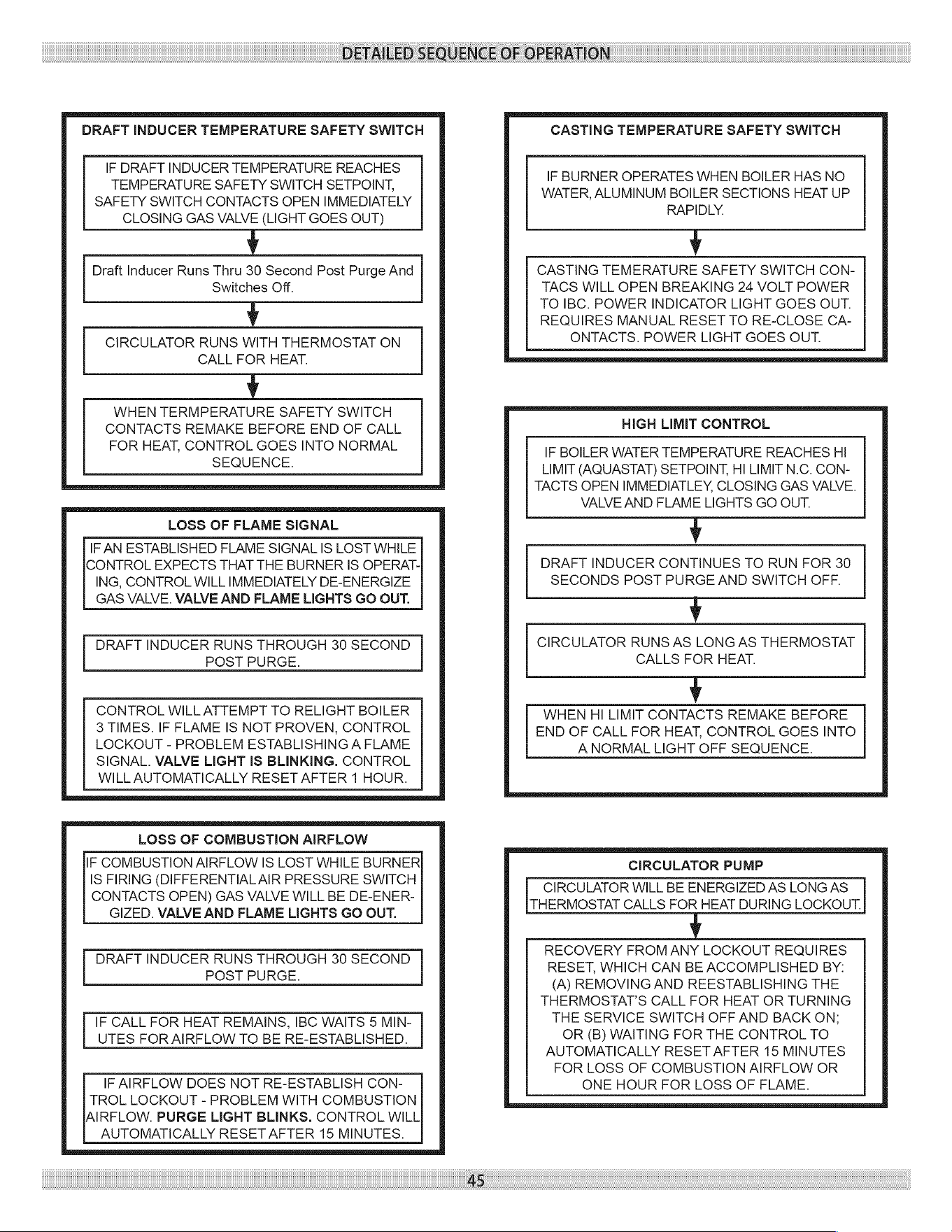
DETAILED
SEQUENCE
OF
OPERATION
DRAFT
INDUCER
TEMPERATURE
SAFETY
SWITCH
IF
DRAFT
INDUCER
TEMPERATURE
REACHES
TEMPERATURE
SAFETY
SWITCH
SETPOINT,
SAFETY
SWITCH
CONTACTS
OPEN
IMMEDIATELY
CLOSING
GAS
VALVE
(LIGHT
GOES
OUT)
v
Draft
Inducer
Runs
Thru
30
Second
Post
Purge
And
Switches
Off.
v
CIRCULATOR
RUNS
WITH
THERMOSTAT
ON
CALL
FOR
HEAT.
v
WHEN
TERMPERATURE
SAFETY
SWITCH
CONTACTS
REMAKE
BEFORE
END
OF
CALL
FOR
HEAT,
CONTROL
GOES
INTO
NORMAL
SEQUENCE.
LOSS
OF
FLAME
SIGNAL
IF
AN
ESTABLISHED
FLAME
SIGNAL
IS
LOST
WHILE
CONTROL
EXPECTS
THAT
THE
BURNER
IS
OPERAT-
ING,
CONTROL
WILL
IMMEDIATELY
DE-ENERGIZE
GAS
VALVE.
VALVE
AND
FLAME
LIGHTS
GO
OUT.
DRAFT
INDUCER
RUNS
THROUGH
30
SECOND
POST
PURGE.
CONTROL
WILL
ATTEMPT
TO
RELIGHT
BOILER
3
TIMES.
IF
FLAME
IS
NOT
PROVEN,
CONTROL
LOCKOUT
-
PROBLEM
ESTABLISHING
A
FLAME
SIGNAL.
VALVE
LIGHT
IS
BLINKING.
CONTROL
WILL
AUTOMATICALLY
RESET
AFTER
1
HOUR.
LOSS
OF
COMBUSTION
AIRFLOW
IF
COMBUSTION
AIRFLOW
IS
LOST
WHILE
BURNER
IS
FIRING
(DIFFERENTIAL
AIR
PRESSURE
SWITCH
CONTACTS
OPEN)
GAS
VALVE
WILL
BE
DE-ENER-
GIZED.
VALVE
AND
FLAME
LIGHTS
GO
OUT.
DRAFT
INDUCER
RUNS
THROUGH
30
SECOND
POST
PURGE.
IF
CALL
FOR
HEAT
REMAINS,
IBC
WAITS
5
MIN-
UTES
FOR
AIRFLOW
TO
BE
RE-ESTABLISHED.
IF
AIRFLOW
DOES
NOT
RE-ESTABLISH
CON-
TROL
LOCKOUT
-
PROBLEM
WITH
COMBUSTION
AIRFLOW.
PURGE
LIGHT BLINKS.
CONTROL
WILL
AUTOMATICALLY
RESET AFTER
15
MINUTES.
45
CASTING
TEMPERATURE
SAFETY
SWITCH
IF
BURNER
OPERATES
WHEN
BOILER
HAS
NO
WATER,
ALUMINUM
BOILER
SECTIONS
HEAT
UP
RAPIDLY.
v
CASTING
TEMERATURE
SAFETY SWITCH
CON-
TACS
WILL
OPEN
BREAKING
24
VOLT
POWER
TO
IBC.
POWER
INDICATOR
LIGHT
GOES
OUT.
REQUIRES
MANUAL
RESET
TO
RE-CLOSE
CA-
ONTACTS.
POWER
LIGHT
GOES
OUT.
HIGH
LIMIT
CONTROL
IF
BOILER
WATER
TEMPERATURE
REACHES
HI
LIMIT
(AQUASTAT)
SETPOINT,
HI
LIMIT
N.C.
CON-
TACTS
OPEN
IMMEDIATLEY,
CLOSING
GAS
VALVE.
VALVE
AND
FLAME
LIGHTS
GO
OUT.
v
DRAFT
INDUCER
CONTINUES
TO
RUN FOR
30
SECONDS
POST
PURGE
AND
SWITCH
OFF.
v
CIRCULATOR
RUNS
AS
LONG
AS
THERMOSTAT
CALLS
FOR
HEAT.
v
WHEN
HI
LIMIT
CONTACTS
REMAKE
BEFORE
END
OF
CALL
FOR
HEAT,
CONTROL
GOES
INTO
A
NORMAL
LIGHT
OFF
SEQUENCE.
CIRCULATOR
PUMP
CIRCULATOR
WILL
BE
ENERGIZED
AS
LONG
AS
THERMOSTAT
CALLS
FOR
HEAT
DURING
LOCKOUT.
v
RECOVERY
FROM
ANY
LOCKOUT
REQUIRES
RESET,
WHICH
CAN
BE
ACCOMPLISHED
BY:
(A)
REMOVING
AND
REESTABLISHING
THE
THERMOSTAT’S
CALL
FOR
HEAT
OR
TURNING
THE
SERVICE
SWITCH
OFF
AND
BACK
ON;
OR
(B)
WAITING
FOR
THE
CONTROL
TO
AUTOMATICALLY
RESET
AFTER
15
MINUTES
FOR
LOSS
OF
COMBUSTION
AIRFLOW
OR
ONE
HOUR
FOR
LOSS
OF
FLAME.
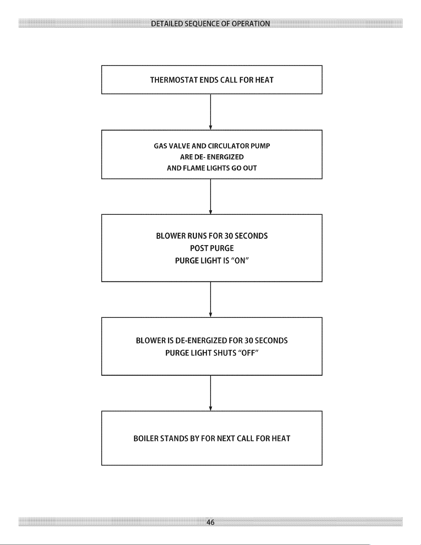
DETAILED
SEQUENCE
OF
OPERATION
THERMOSTAT
ENDS
CALL
FOR
HEAT
Vv
GAS
VALVE
AND
CIRCULATOR
PUMP
ARE
DE-
ENERGIZED
AND
FLAME
LIGHTS
GO
OUT
BLOWER
RUNS
FOR
30
SECONDS
POST
PURGE
PURGE
LIGHT
IS
“ON”
BLOWER
IS
DE-ENERGIZED
FOR
30
SECONDS
PURGE
LIGHT
SHUTS
“OFF”
BOILER
STANDS
BY
FOR
NEXT
CALL
FOR
HEAT
46
A
property
damage,
severe
injury
or
death.
TROUBLESHOOTING
2.
Troubleshooting
tools:
A.
Voltmeter
to
check
120
vac
and
24
vac
Fire,
explosion
or
shock
hazard
may
cause
B.
Continuity
tester.
WARNING
C.
Inclined
manometer
or
pressure
gauge
with
0-2.0”
Range
(0.01”
Scale)
for
measuring
suction
pressures
at
pressure
switch.
Do
not
attempt
to
modify
the
physical
or
electrical
characteristics
of
this
boiler
in
any
way.
D.
U-tube
manometer
or
differential
pressure
gauge
with
important
0-14”
range
(0.1”
Scale)
for
measuring
inlet
and
manifold
1.
In
a
reset
from
lockout
condition,
all
electrical
meter
readings
gas
pressures.
at
the
gas
control
valve
(24
vac)
must
be
taken
within
the
trial
3.
What
is
system
status?
for
ignition
period.
A.
Consult
the
chart
on
the
following
page.
If
any
component
does
not
function
properly,
make
sure
it
is
B.
Figure
#16
shows
the
location
on
the
boiler
of
the
correctly
installed
and
wired
before
replacing
it.
diagnostic
indicator
lamps.
Static
electricity
discharge
can
damage
the
integrated
boiler
control
(IBC).
Touch
metal
surface
to
discharge
static
electricity
before
touching
IBC.
The
IBC
cannot
be
repaired.
If
it
malfunctions
it
must
be
replaced.
Only
trained,
experienced
service
technicians
should
service
the
IBC
systems.
Following
troubleshooting,
check
out
the
system
following
the
sequence
of
operation
section
of
this
chapter
for
a
normal
light
off
sequence.
All
controls
are
factory
tested
in
the
assembly
process
and
a
defective
control
is
generally
the
least
likely
cause.
If
you
suspect
you
have
a
defective
control,
read
through
the
troubleshooting
chart
before
you
replace
it.
It is
extremely
unlikely
that
the
two
consecutive
controls
are
defective.
If
it
seems
to
be
happening,
chances
are
that
either
there
is
nothing
wrong
with
the
contorl
or
it
is
being
damaged
by
some
other
problem
(an
electrical
short
burning
out
a
transformer,
for
example).
Initial
Service
Checks
1.
Before
troubleshooting:
A.
Make
sure
that
circuit
breaker
is
on
or
fuse
is
ok
at
electrical
panel.
B.
Make
sure
that
service
switch
is
on.
C.
Make
sure
that
gas
is
on
at
the gas
meter,
at
all
appropriate
manual
shutoff
valves
and
at
the
gas
control
valve.
D.
Make
sure
that
the
thermostat
is
calling
for
heat.
E.
Check
that
wire
connectors
at
the
integrated
boiler
control
and
at
the
originating
control
are
securely
plugged
in
or
connected.
F.
Check
that
hoses
are
securely
connected
and
are
not
plugged
in
or
damaged.
47
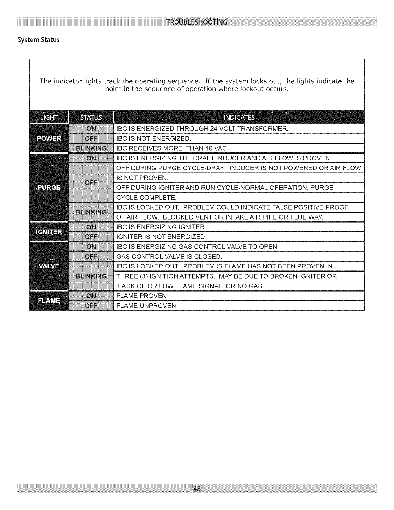
TROUBLESHOOTING
System
Status
The
indicator
lights
track
the
operating
sequence.
If
the
system
locks
out,
the
lights
indicate
the
point
in
the
sequence
of
operation
where
lockout
occurs.
IBC
IS
ENERGIZED
THROUGH
24
VOLT
TRANSFORMER.
IBC
IS
NOT
ENERGIZED.
IBC
RECEIVES
MORE
THAN
40
VAC
IBC
IS
ENERGIZING
THE
DRAFT
INDUCER
AND
AIR
FLOW
IS
PROVEN.
OFF
DURING
PURGE
CYCLE-DRAFT
INDUCER
IS
NOT
POWERED
OR
AIR
FLOW
IS
NOT
PROVEN.
OFF
DURING
IGNITER
AND
RUN
CYCLE-NORMAL
OPERATION,
PURGE
CYCLE
COMPLETE.
IBC
IS
LOCKED
OUT.
PROBLEM
COULD
INDICATE
FALSE
POSITIVE
PROOF
OF
AIR
FLOW.
BLOCKED
VENT
OR
INTAKE
AIR
PIPE
OR
FLUE
WAY.
IBC
IS
ENERGIZING
IGNITER
IGNITER
IS
NOT
ENERGIZED
IBC
IS
ENERGIZING
GAS
CONTROL
VALVE
TO
OPEN.
GAS
CONTROL
VALVE
IS
CLOSED.
IBC
IS
LOCKED
OUT.
PROBLEM
IS
FLAME
HAS
NOT
BEEN
PROVEN
IN
THREE
(3)
IGNITION
ATTEMPTS.
MAY
BE
DUE
TO
BROKEN
IGNITER
OR
LACK
OF
OR
LOW
FLAME
SIGNAL,
OR
NO
GAS.
FLAME
PROVEN
FLAME
UNPROVEN
48
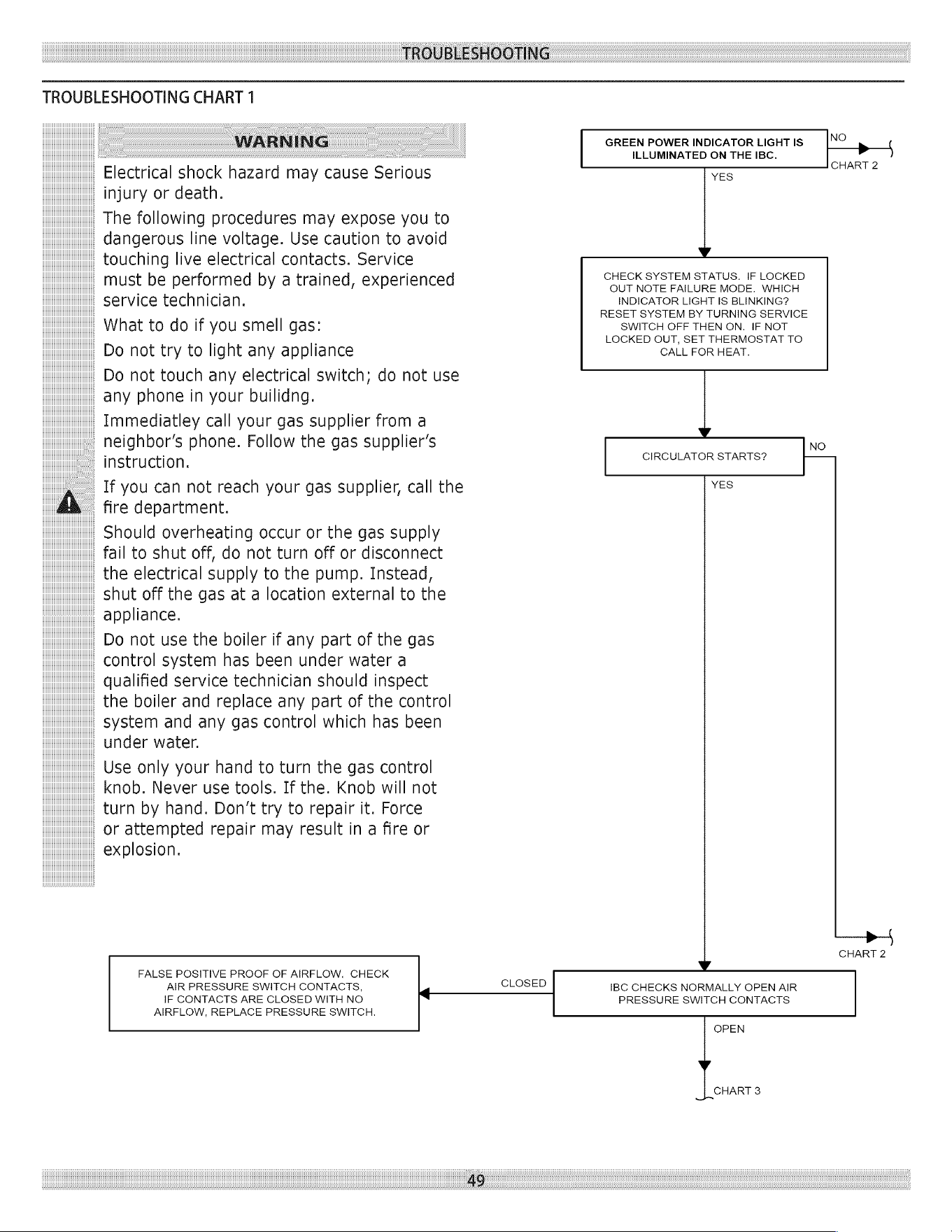
TROUBLESHOOTING
TROUBLESHOOTING
CHART
1
WARNING
GREEN
POWER
INDICATOR
LIGHT
IS
NO
>
ILLUMINATED
ON
THE
IBC.
CHART
2
Electrical
shock
hazard
may
cause
Serious
YES
injury
or
death.
The
following
procedures
may
expose
you
to
dangerous
line
voltage.
Use
caution
to
avoid
touching
live
electrical
contacts.
Service
i i
CHECK SYSTEM
STATUS.
IF
LOCKED
must
be
performed
by
a
trained,
experienced
OUT
NOTE
FAILURE
MODE.
WHICH
service
technician.
INDICATOR
LIGHT
IS
BLINKING?
.
RESET
SYSTEM
BY
TURNING
SERVICE
What
to
do
if
you
smell
gas:
SWITCH
OFF
THEN
ON.
IF
NOT
. .
LOCKED
OUT,
SET
THERMOSTAT
TO
Do
not
try
to
light
any
appliance
CALL
FOR
HEAT.
Do
not
touch
any
electrical
switch;
do
not
use
any
phone
in
your
builidng.
Immediatley
call
your
gas
supplier
from
a
v
neighbor’s
phone.
Follow
the
gas
supplier’s
NO
instru
ction
CIRCULATOR
STARTS?
If
you
can
not
reach
your
gas
supplier,
call
the
YES
A
fire
department.
Should
overheating
occur
or
the
gas
supply
fail
to
shut
off,
do
not
turn
off
or
disconnect
the
electrical
supply
to
the
pump.
Instead,
shut
off
the
gas
at
a
location
external
to
the
appliance.
Do
not
use
the
boiler
if
any
part
of
the
gas
control
system
has
been
under
water
a
qualified
service
technician
should
inspect
the
boiler
and
replace
any
part
of
the
control
system
and
any
gas
control
which
has
been
under
water.
Use
only
your
hand
to
turn
the
gas control
knob.
Never
use
tools.
If
the.
Knob
will
not
turn
by
hand.
Don’t
try
to
repair
it.
Force
or
attempted
repair
may
result
in
a
fire
or
explosion.
CHART
2
FALSE
POSITIVE
PROOF
OF
AIRFLOW.
CHECK ¥
AIR
PRESSURE
SWITCH
CONTACTS,
‘
CLOSED
IBC
CHECKS
NORMALLY
OPEN
AIR
IF
CONTACTS
ARE
CLOSED
WITH
NO
PRESSURE
SWITCH
CONTACTS
AIRFLOW,
REPLACE
PRESSURE
SWITCH.
OPEN
CHART
3
49
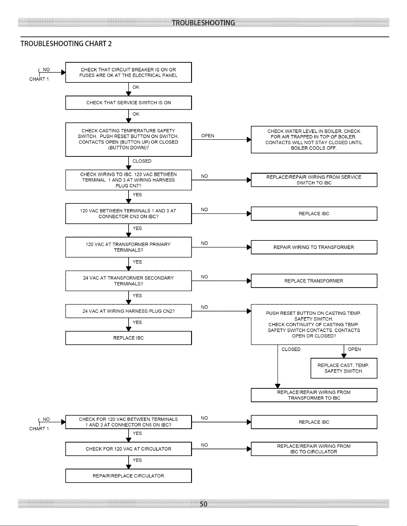
TROUBLESHOOTING
TROUBLESHOOTING
CHART
2
NO
CHECK
THAT
CIRCUIT
BREAKER
IS
ON
OR
FUSES
ARE
OK
AT
THE
ELECTRICAL
PANEL
CHART
1
J
OK
CHECK
THAT
SERVICE
SWITCH
IS
ON
J
OK
CHECK
CASTING
TEMPERATURE
SAFETY
CHECK
WATER
LEVEL
IN
BOILER.
CHECK
SWITCH.
PUSH
RESET
BUTTON
ON
SWITCH.
OPEN
>
FOR
AIR
TRAPPED
IN
TOP
OF
BOILER.
CONTACTS
OPEN
(BUTTON
UP)
OR
CLOSED
CONTACTS
WILL
NOT
STAY
CLOSED
UNTIL
(BUTTON
DOWN)?
BOILER
COOLS
OFF.
J
CLOSED
CHECK
WIRING
TO
IBC.
120
VAC
BETWEEN
NO
TERMINAL
1
AND
3
AT
WIRING
HARNESS
———
REPLACE!
Tee
ren
Toe
SERVICE
PLUG
CN7?
J
YES
420
VAC
BETWEEN
TERMINALS
1
AND
3
AT
NO
CONNECTOR
CN3
ON
IBC?
>
REPLACE
IBC
J
YES
420
VAC
AT
TRANSFORMER
PRIMARY
NO
+}
TERMINALS?
REPAIR
WIRING
TO
TRANSFORMER
J
YES
24
VAC
AT
TRANSFORMER
SECONDARY
NO
|}-—_______—__—__—_>
TERMINALS?
REPLACE
TRANSFORMER
J
YES
NO
24
VAC
AT
WIRING
HARNESS
PLUG
CN2?
(——
PUSH
RESET
BUTTON
ON
CASTING
TEMP.
SAFETY
SWITCH.
J
YES
CHECK
CONTINUITY
OF
CASTING
TEMP.
SAFETY SWITCH
CONTACTS.
CONTACTS
REPLACE
IBC
OPEN
OR
CLOSED?
CLOSED
J
OPEN
REPLACE
CAST.
TEMP.
SAFETY
SWITCH.
REPLACE/REPAIR
WIRING
FROM
TRANSFORMER
TO
IBC
NO
CHECK
FOR
120
VAC
BETWEEN
TERMINALS
NO
+
AND
3
AT
CONNECTOR
CN5
ON
IBC?
>
REPLACE
IBC
CHART
1
J
YES
NO
CHECK
FOR
120
VAC
AT
CIRCULATOR
>
REPLACE/REPAIR
WIRING
FROM
J
YES
REPAIR/REPLACE
CIRCULATOR
IBC
TO
CIRCULATOR
50
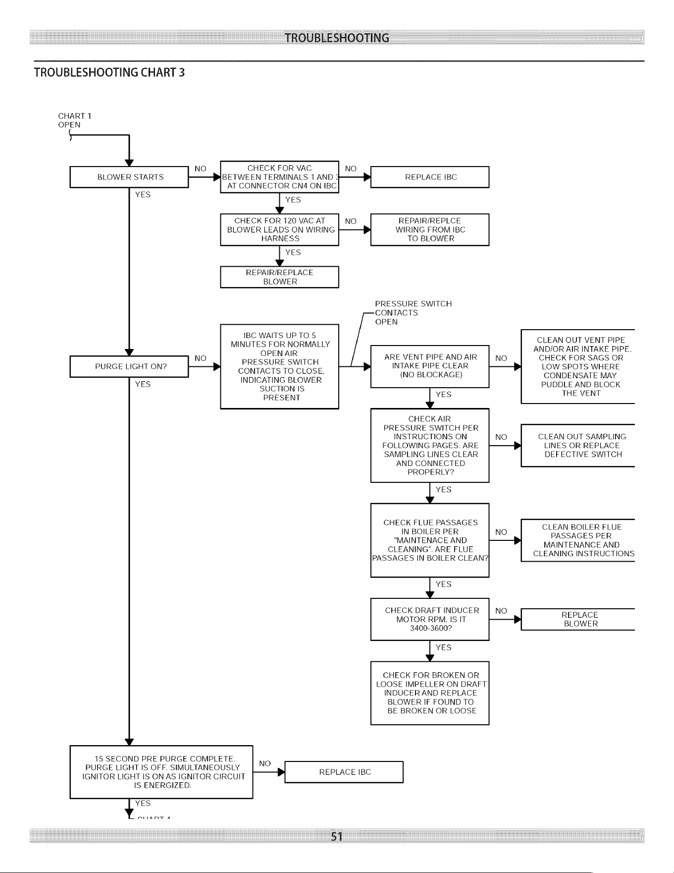
TROUBLESHOOTING
IS
ENERGIZED.
y
51
TROUBLESHOOTING
CHART
3
CHART
1
OPEN
Vv
NO
CHECK
FOR
VAC
NO
BLOWER
STARTS
+>
BETWEEN
TERMINALS
1
AND
+——>
REPLACE
IBC
AT
CONNECTOR
CN4
ON
IBC
YES
y
5
CHECK
FOR
120
VAC
AT
NO
REPAIR/REPLCE
BLOWER
LEADS
ON
WIRING
-/}——>
WIRING
FROM
IBC
HARNESS
TO
BLOWER
ye
REPAIR/REPLACE
BLOWER
PRESSURE
SWITCH
CONTACTS
OPEN
IBC
WAITS
UP
TO
5
MINUTES
FOR
NORMALLY
¥
NO
PRESSURE
SWITCH
ARE
VENT
PIPEANDAIR
|
No
PURGE
LIGHT
ON?
+———>
INTAKE
PIPE
CLEAR
|}
CONTACTS
TO
CLOSE,
(NO
BLOCKAGE)
YES
INDICATING
BLOWER
SUCTION
IS
PRESENT
ve
CHECK
AIR
PRESSURE
SWITCH
PER
INSTRUCTIONS
ON NO
FOLLOWING
PAGES.
ARE
SAMPLING
LINES
CLEAR
AND
CONNECTED
PROPERLY?
ye
CHECK
FLUE
PASSAGES
IN
BOILER
PER
NO
"MAINTENACE
AND
+>}
CLEANING".
ARE
FLUE
PASSAGES
IN
BOILER
CLEAN?
ys
CHECK
DRAFT
INDUCER
|
NO
MOTOR
RPM.
IS
IT
|—_——_}>}
3400-3600?
ue
CHECK
FOR
BROKEN
OR
LOOSE
IMPELLER
ON
DRAFT
INDUCER
AND
REPLACE
BLOWER
IF
FOUND
TO
BE
BROKEN
OR
LOOSE
Vv.
15
SECOND
PRE
PURGE
COMPLETE.
NO
PURGE
LIGHT
IS
OFF.
SIMULTANEOUSLY
IGNITOR
LIGHT
IS
ON
AS
IGNITOR
CIRCUIT
>
REPLACE
IBC
CLEAN
OUT
VENT
PIPE
AND/OR
AIR
INTAKE
PIPE.
CHECK
FOR
SAGS
OR
LOW
SPOTS
WHERE
CONDENSATE
MAY
PUDDLE
AND
BLOCK
THE
VENT
CLEAN
OUT
SAMPLING
LINES
OR
REPLACE
DEFECTIVE
SWITCH
CLEAN
BOILER
FLUE
PASSAGES
PER
MAINTENANCE
AND
CLEANING
INSTRUCTIONS
REPLACE
BLOWER
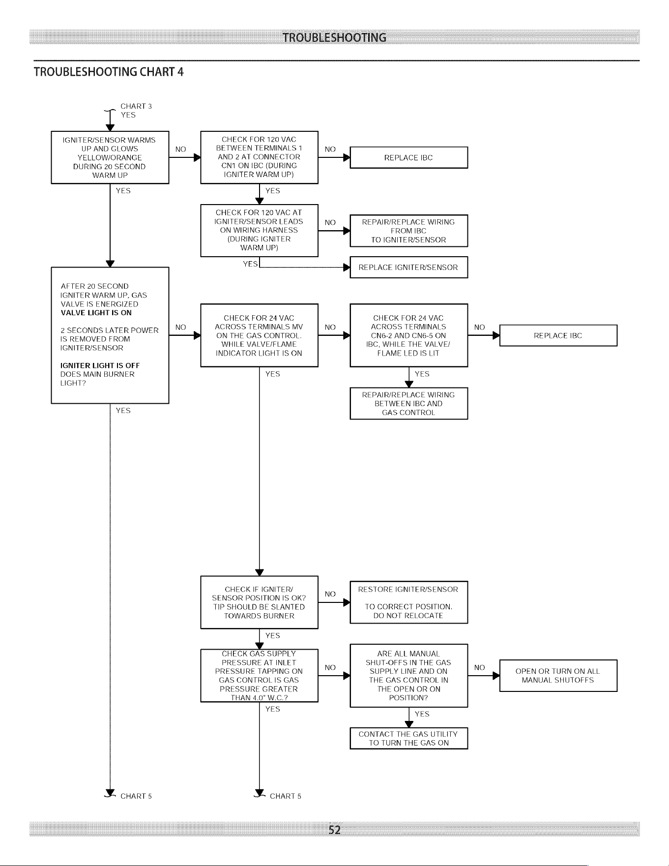
TROUBLESHOOTING
CHART
3
YES
TROUBLESHOOTING
CHART
4
IGNITER/SENSOR
WARMS,
CHECK
FOR
120
VAC
REPLACE
IBC
REPAIR/REPLACE
WIRING
FROM
IBC
TO
IGNITER/SENSOR
REPLACE
IGNITER/SENSOR
CHECK
FOR
24
VAC
ACROSS
TERMINALS
CN6-2
AND
CN6-5
ON
IBC,
WHILE
THE
VALVE/
FLAME
LED
IS
LIT
NO
REPLACE
IBC
i
REPAIR/REPLACE
WIRING
BETWEEN
IBC
AND
GAS
CONTROL
RESTORE
IGNITER/SENSOR
TO
CORRECT
POSITION.
DO
NOT
RELOCATE
ARE
ALL
MANUAL
SHUT-OFFS
IN
THE
GAS
SUPPLY
LINE
AND
ON
THE
GAS
CONTROL
IN
THE
OPEN
OR
ON
POSITION?
NO
OPEN
OR
TURN
ON
ALL
MANUAL
SHUTOFFS
ye
CONTACT
THE
GAS
UTILITY
TO
TURN
THE
GAS
ON
UP
AND
GLOWS
NO
BETWEEN
TERMINALS
1
NO
YELLOW/ORANGE
iH
AND
2
AT
CONNECTOR
+}
DURING
20
SECOND
CN1
ON
IBC
(DURING
WARM
UP
IGNITER
WARM
UP)
YES
ye
CHECK
FOR
120
VAC
AT
IGNITER/SENSOR
LEADS
NO
ON
WIRING
HARNESS
|}
___BpI
(DURING
IGNITER
WARM
UP)
YeEs|
>
AFTER
20
SECOND
IGNITER
WARM
UP,
GAS
VALVE
IS
ENERGIZED
VALVE
LIGHT
IS
ON
CHECK
FOR
24
VAC
NO
ACROSS
TERMINALS
MV
NO
2
SECONDS
LATER
POWER
IS
REMOVED
FROM
i
ON
THE
GAS
CONTROL.
+>
IGNITERISENSOR
WHILE
VALVE/FLAME
~
INDICATOR
LIGHT
IS
ON
IGNITER
LIGHT
IS
OFF
DOES
MAIN
BURNER
YES
LIGHT?
YES
Vv
CHECK
IF
IGNITER/
NO
SENSOR
POSITION
IS
OK?
TIP
SHOULD
BE
SLANTED
>
TOWARDS
BURNER
YES
CHECK
GAS
SUPPLY
PRESSURE
AT
INLET NO
PRESSURE
TAPPING
ON
GAS
CONTROL
IS
GAS
>
PRESSURE
GREATER
THAN
4.0"
W.C.?
YES
¥
cuarrs
CHART
5
52
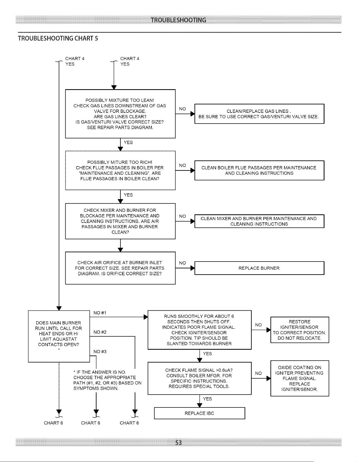
TROUBLESHOOTING
TROUBLESHOOTING
CHART
5
_.
CHART
4
CHART
4
YES
YES
POSSIBLY
MIXTURE
TOO
LEAN!
CHECK
GAS
LINES
DOWNSTREAM
OF
GAS
VALVE
FOR
BLOCKAGE.
ARE GAS
LINES
CLEAR?
IS
GAS/VENTURI
VALVE
CORRECT
SIZE?
SEE
REPAIR
PARTS
DIAGRAM.
NO
CLEAN/REPLACE
GAS
LINES
.
BE
SURE
TO
USE
CORRECT
GAS/VENTURI
VALVE
SIZE.
yi
POSSIBLY
MITURE
TOO
RICH!
CHECK
FLUE
PASSAGES
IN
BOILER
PER
"MAINTENANCE
AND
CLEANING".
ARE
FLUE
PASSAGES
IN
BOILER
CLEAN?
NO
CLEAN
BOILER
FLUE
PASSAGES
PER
MAINTENANCE
AND
CLEANING
INSTRUCTIONS
i
CHECK
MIXER
AND
BURNER
FOR
BLOCKAGE
PER
MAINTENANCE
AND
CLEANING
INSTRUCTIONS.
ARE
AIR
PASSAGES
IN
MIXER
AND
BURNER
CLEAN?
NO
CLEAN
MIXER
AND
BURNER
PER
MAINTENANCE
AND
CLEANING
INSTRUCTIONS
‘
CHECK
AIR
ORIFICE
AT
BURNER
INLET
FOR
CORRECT
SIZE.
SEE
REPAIR
PARTS
DIAGRAM.
IS
ORIFICE
CORRECT
SIZE?
NO
REPLACE
BURNER
Vv
DOES
MAIN
BURNER
RUN
UNTIL
CALL
FOR
HEAT
ENDS
OR
HI
LIMIT
AQUASTAT
CONTACTS
OPEN?
pNom
RUNS
SMOOTHLY
FOR
ABOUT
6
SECONDS
THEN
SHUTS
OFF.
RESTORE
INDICATES
POOR
FLAME
SIGNAL.
NO
>
IGNITER/SENSOR
NO
#2
CHECK
IGNITER/SENSOR
TO
CORRECT
POSITION.
POSITION.
TIP
SHOULD
BE
DO
NOT
RELOCATE.
SLANTED
TOWARDS
BURNER
NO
#3
y=
|
OXIDE
COATING
ON
CHOOSE
THE
APPROPRIATE
:
+>
FLAME
SIGNAL.
PATH
(#1,
#2,
OR
#3)
BASED
ON
SPECIFIC
INSTRUCTIONS.
REPLACE
SYMPTOMS
SHOWN. REQUIRES
SPECIAL
TOOLS.
IGNITER/SENOR.
CHART
6
CHART
6
.
CHART
6
y=
REPLACE
IBC
53
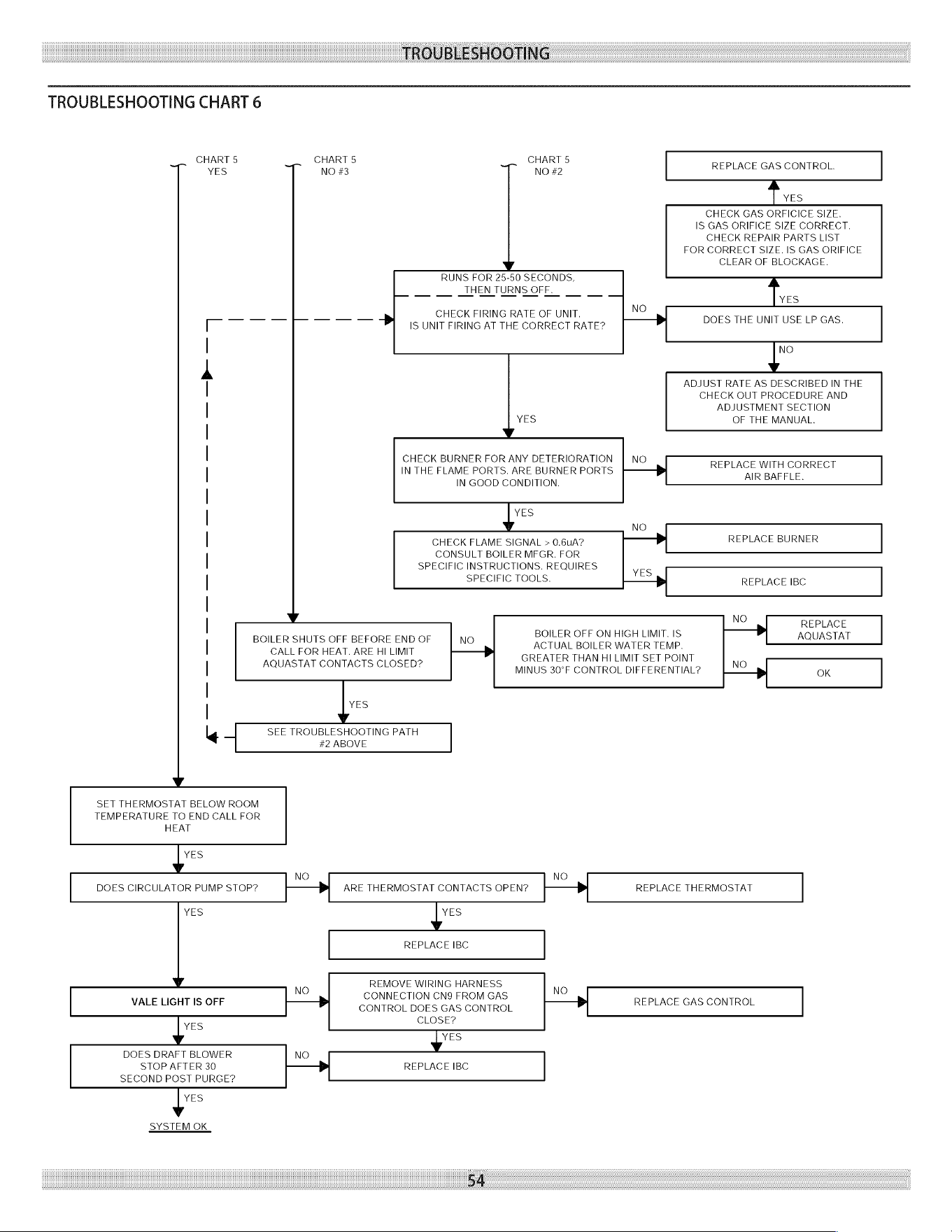
TROUBLESHOOTING
TROUBLESHOOTING
CHART
6
CHART
5
CHART
5
CHART
5
YES
NO
#3
NO
#2
REPLACE
GAS
CONTROL.
Fives
————
+
RUNS
FOR
25-50
SECONDS,
|
____THENTURNS
OFF.
CHECK
FIRING
RATE
OF
UNIT.
IS
UNIT
FIRING
AT
THE
CORRECT
RATE?
CHECK
GAS
ORFICICE
SIZE.
IS
GAS ORIFICE
SIZE
CORRECT.
CHECK
REPAIR
PARTS
LIST
FOR
CORRECT
SIZE.
IS
GAS
ORIFICE
CLEAR
OF
BLOCKAGE.
Ties
NO
DOES
THE
UNIT
USE
LP
GAS.
{°
ADJUST
RATE
AS
DESCRIBED
IN
THE
CHECK
OUT
PROCEDURE
AND
ADJUSTMENT
SECTION
YES
OF
THE
MANUAL.
CHECK
BURNER
FOR
ANY
DETERIORATION
|
NO
IN
THE
FLAME
PORTS.
ARE
BURNER
PORTS
->-——
ee
GAIL
IN
GOOD
CONDITION.
ye
No
CHECK
FLAME
SIGNAL
>
0.6uA?
-——>
REPLACE
BURNER
CONSULT
BOILER
MFGR.
FOR
SPECIFIC
INSTRUCTIONS.
REQUIRES
ves
SPECIFIC
TOOLS.
REPLACE
IBC
¥v
NO
>
REPLACE
BOILER
SHUTS
OFE
BEFORE
ENDOE
|
NO
BOILER
OFF
ON
HIGH
LIMIT,
IS
AQUASTAT
ACTUAL
BOILER
WATER
TEMP.
CALL
FOR
HEAT.
ARE
HI
LIMIT
|_$_
AOQUASTAT
CONTACTS
CLOSED?
GREATER
THAN
HI
LIMIT
SET
POINT
NO
MINUS
30°F
CONTROL
DIFFERENTIAL?
=
LNO_
OK
YES
TTT
TT
TT TT TT
TTT
SEE
TROUBLESHOOTING
PATH
#2
ABOVE
Vv
SET
THERMOSTAT
BELOW
ROOM
TEMPERATURE
TO
END
CALL
FOR
HEAT
ye
NO NO
DOES
CIRCULATOR
PUMP
STOP?
i
ARE
THERMOSTAT
CONTACTS
OPEN?
=[-——
REPLACE
THERMOSTAT
YES
i
REPLACE
IBC
NO
REMOVE
WIRING
HARNESS
NO
CONNECTION
CN9
FROM
GAS
VALE
LIGHT
IS
OFF
CONTROL
DOES
GAS
CONTROL
1+
REPLACE
GAS
CONTROL
?
VES
CLOSE?
vw
DOES
DRAFT
BLOWER
NO
STOP
AFTER
30
REPLACE
IBC
SECOND
POST
PURGE?
y
SYSTEM
OK
54
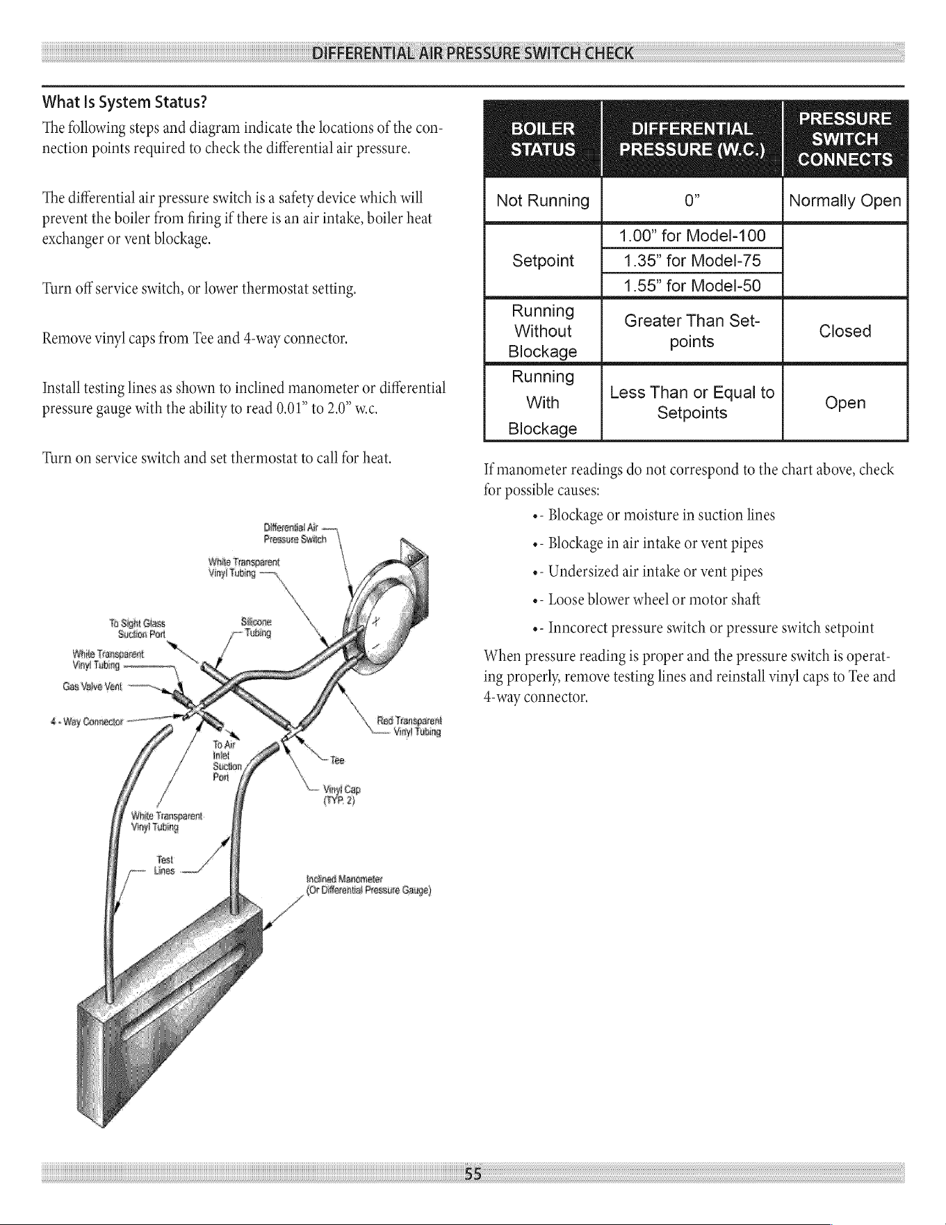
DIFFERENTIAL
AIR
PRESSURE
SWITCH
CHECK:
What
Is
System
Status?
The
following
steps
and
diagram
indicate
the
locations
of
the
con-
nection
points
required
to
check
the
differential
air
pressure.
The
differential
air
pressure
switch
is
a
safety
device
which
will
prevent
the
boiler
from
firing
if
there
is
an
air
intake,
boiler
heat
exchanger
or
vent
blockage.
Turn
off
service
switch,
or
lower
thermostat
setting.
Remove
vinyl
caps
from
Tee
and
4-way
connector.
Install
testing
lines
as
shown
to
inclined
manometer
or
differential
pressure
gauge
with
the
ability
to
read
0.01”
to
2.0”
wc.
Turn
on
service
switch
and
set
thermostat
to
call
for
heat.
Oiterential
Air
.
Preseue
Swi
|
White
Transparent
Vinyl
Tubing
‘
To
Sight
Glass
Silicone
Suction
Port
o>
Fubing
White
Transparent
Vinyl
Tubing
ey
Gas
Valve
Vent
-—-
\
Red
Transparent
eM ip
4.
Way
Cannecture—
{
My
»
Vinyl
Tobing
NS
“Tee
\
vin
Cap
(VP
2)
White
Transparent
Vinyl
Tubing
Test
rome
Lan
—/
incined
Manometer
_AOr
Difarential
Pressure
Gauge)
55
BOILER
Sige
sa
ee
re
ed
ni
meo
ye
aden
(1)
Not
Running
0”
PRESSURE
yes
CONNECTS
Normally
Open
1.00”
for
Model-100
Setpoint
1.35”
for
Model-75
1.55”
for
Model-50
Running
Without
Greater
Than Set
Closed
Blockage
P
Running
With
Less
Than
or
Equal
to
Open
Setpoints
Blockage
If
manometer
readings
do
not
correspond
to
the
chart
above,
check
for
possible
causes:
e-
Blockage
or
moisture
in
suction
lines
e-
Blockage
in
air
intake
or
vent
pipes
¢-
Undersized
air
intake
or
vent
pipes
e-
Loose
blower wheel
or
motor
shaft
¢-
Inncorect
pressure
switch
or
pressure
switch
setpoint
When
pressure
reading
is
proper
and
the
pressure
switch
is
operat-
ing
properly,
remove
testing
lines
and
reinstall
vinyl
caps
to
Tee
and
4-way
connector,

“
85
Middle
Rd.
Dunkirk’
Dunkirk,
NY
14048