Desktop PC
User Guide
G700TF/G700TF_US

2
SERVICE AND SUPPORT
Visit our multi-language website at https://www.asus.com/support/.
Copyright © 2025 ASUSTeK Computer Inc. All Rights Reserved.
No part of this manual, including the products and software described in it, may be reproduced,
transmitted, transcribed, stored in a retrieval system, or translated into any language in any form or by any
means, except documentation kept by the purchaser for backup purposes, without the express written
permission of ASUSTeK Computer Inc. (“ASUS”).
Product warranty or service will not be extended if: (1) the product is repaired, modied or altered, unless
such repair, modication of alteration is authorized in writing by ASUS; or (2) the serial number of the
product is defaced or missing.
ASUS PROVIDES THIS MANUAL “AS IS” WITHOUT WARRANTY OF ANY KIND, EITHER EXPRESS
OR IMPLIED, INCLUDING BUT NOT LIMITED TO THE IMPLIED WARRANTIES OR CONDITIONS OF
MERCHANTABILITY OR FITNESS FOR A PARTICULAR PURPOSE. IN NO EVENT SHALL ASUS, ITS
DIRECTORS, OFFICERS, EMPLOYEES OR AGENTS BE LIABLE FOR ANY INDIRECT, SPECIAL, INCIDENTAL,
OR CONSEQUENTIAL DAMAGES (INCLUDING DAMAGES FOR LOSS OF PROFITS, LOSS OF BUSINESS,
LOSS OF USE OR DATA, INTERRUPTION OF BUSINESS AND THE LIKE), EVEN IF ASUS HAS BEEN ADVISED
OF THE POSSIBILITY OF SUCH DAMAGES ARISING FROM ANY DEFECT OR ERROR IN THIS MANUAL OR
PRODUCT.
SPECIFICATIONS AND INFORMATION CONTAINED IN THIS MANUAL ARE FURNISHED FOR
INFORMATIONAL USE ONLY, AND ARE SUBJECT TO CHANGE AT ANY TIME WITHOUT NOTICE, AND
SHOULD NOT BE CONSTRUED AS A COMMITMENT BY ASUS. ASUS ASSUMES NO RESPONSIBILITY OR
LIABILITY FOR ANY ERRORS OR INACCURACIES THAT MAY APPEAR IN THIS MANUAL, INCLUDING THE
PRODUCTS AND SOFTWARE DESCRIBED IN IT.
Products and corporate names appearing in this manual may or may not be registered trademarks or
copyrights of their respective companies, and are used only for identication or explanation and to the
owners’ benet, without intent to infringe.
E25465
First Edition
January 2025

3
Contents
Contents .............................................................................................................. 3
Notices ................................................................................................................ 5
Conventions used in this guide ........................................................................ 13
Safety information ............................................................................................ 14
Where to nd more information ....................................................................... 17
Package contents ............................................................................................. 18
Chapter 1 Getting started
Welcome! ........................................................................................................... 19
Getting to know your computer ........................................................................ 19
Setting up your computer ................................................................................. 30
Turning your computer ON ............................................................................... 34
Enabling fast startup ........................................................................................ 34
Chapter 2 Connecting devices to your computer
Connecting a USB storage device .................................................................... 35
Connecting microphone and speakers ............................................................ 36
Changing to the external audio output ............................................................ 39
Connecting multiple external displays............................................................. 40
Chapter 3 Using your computer
Proper posture when using your Desktop PC ................................................. 41
Conguring the USB ports using the BIOS ...................................................... 42
Conguring the HDD security setting using the BIOS ..................................... 43
Conguring the Keyboard/Mouse using the BIOS (on selected models only) 44
Chapter 4 Connecting to the Internet
Wired connection .............................................................................................. 45
Wi-Fi moving antenna installation .................................................................... 49
Chapter 5 Troubleshooting
Troubleshooting ................................................................................................ 51
MyASUS in WinRE ............................................................................................. 58
Appendix Working with Windows
®
Starting for the rst time .................................................................................. 59
Start menu ......................................................................................................... 59

4
Windows
®
apps ................................................................................................. 60
Connecting to wireless networks ..................................................................... 60
Connecting to wired networks ......................................................................... 61
Turning your computer off ................................................................................ 61
Putting your computer to the Off mode / the lowest power mode ................ 62
Putting your computer to sleep ........................................................................ 62

5
Notices
ASUS Recycling/Takeback Services
ASUS recycling and takeback programs come from our commitment to the highest standards
for protecting our environment. We believe in providing solutions for you to be able to
responsibly recycle our products, batteries, other components, as well as the packaging
materials. Please go to https://esg.asus.com/en/Takeback.htm for the detailed recycling
information in different regions.
REACH
Complying with the REACH (Registration, Evaluation, Authorisation, and Restriction of
Chemicals) regulatory framework, we published the chemical substances in our products at
ASUS REACH website at https://esg.asus.com/Compliance.htm.
Federal Communications Commission Statement
This device complies with Part 15 of the FCC Rules. Operation is subject to the following two
conditions:
• This device may not cause harmful interference; and
• This device must accept any interference received including interference that may cause
undesired operation.
This equipment has been tested and found to comply with the limits for a Class B digital
device, pursuant to Part 15 of the FCC Rules. These limits are designed to provide reasonable
protection against harmful interference in a residential installation. This equipment generates,
uses and can radiate radio frequency energy and, if not installed and used in accordance
with manufacturer’s instructions, may cause harmful interference to radio communications.
However, there is no guarantee that interference will not occur in a particular installation. If
this equipment does cause harmful interference to radio or television reception, which can be
determined by turning the equipment off and on, the user is encouraged to try to correct the
interference by one or more of the following measures:
• Reorient or relocate the receiving antenna.
• Increase the separation between the equipment and receiver.
• Connect the equipment to an outlet on a circuit different from that to which the receiver
is connected.
• Consult the dealer or an experienced radio/TV technician for help.
FCC RF Exposure information
This equipment must be installed and operated in accordance with provided instructions and
the antenna(s) used for this transmitter must be installed to provide a separation distance of
at least 20 cm from all persons and must not be co-located or operating in conjunction with
any other antenna or transmitter. End-users and installers must be provided with antenna
installation instructions and transmitter operating conditions for satisfying.
FCC RF Caution Statement
WARNING: Any changes or modications not expressly approved by the party responsible for
compliance could void your authority to operate the equipment.
6
The use of shielded cables for connection of the monitor to the graphics card is required
to assure compliance with FCC regulations. Changes or modications to this unit not
expressly approved by the party responsible for compliance could void the user’s authority
to operate this equipment.
CAUTION: Danger of explosion if battery is incorrectly replaced. Replace only with the
same or equivalent type recommended by the manufacturer. Dispose of used batteries
according to the manufacturer’s instructions.
Lithium Battery Warning
ATTENTION! Danger d’explosion si la batterie n’est pas correctement remplacée.
Remplacer uniquement avec une batterie de type semblable ou équivalent,
recommandée par le fabricant. Jeter les batteries usagées conformément aux
instructions du fabricant.
Avertissement relatif aux batteries Lithium
Compliance Statement of Innovation, Science and Economic
Development Canada (ISED)
This device complies with Innovation, Science, and Economic Development Canada licence
exempt RSS standard(s). Operation is subject to the following two conditions: (1) this device
may not cause interference, and (2) this device must accept any interference, including
interference that may cause undesired operation of the device:
Operation in the band 5150–5250 MHz is only for indoor use to reduce the potential for
harmful interference to co-channel mobile satellite systems.
CAN ICES (B) / NMB (B)
Déclaration de conformité de Innovation, Sciences et Développement
économique Canada (ISED)
Le présent appareil est conforme aux CNR d’Innovation, Sciences et Développement
économique Canadaapplicables aux appareils radio exempts de licence. L’exploitation est
autorisée aux deux conditions suivantes : (1) l’appareil ne doit pas produire de brouillage,
et (2) l’utilisateur de l’appareil doit accepter tout brouillage radioélectrique subi, même si le
brouillage est susceptible d’en compromettre le fonctionnement.
La bande 5150 – 5250 MHz est réservée uniquement pour une utilisation à l’intérieur an de
réduire les risques de brouillage préjudiciable aux systèmes de satellites mobiles utilisant les
mêmes canaux.
CAN ICES (B) / NMB (B)
7
IC: Canadian Compliance Statement
Complies with the Canadian ICES-003 Class B specications. This device complies with RSS
210 of Industry Canada. This Class B device meets all the requirements of the Canadian
interference-causing equipment regulations.
This device complies with Industry Canada license exempt RSS standard(s). Operation is
subject to the following two conditions: (1) this device may not cause interference, and (2)
this device must accept any interference, including interference that may cause undesired
operation of the device.
Déclaration de conformité d’Industrie Canada
Cet appareil numérique de la classe B est conforme à la norme NMB-003 du Canada. Cet
appareil numérique de la classe B respecte toutes les exigences du Règlement sur le matériel
brouilleur du Canada.
Le présent appareil est conforme aux normes CNR d’Industrie Canada applicables aux
appareils radio exempts de licence. Son utilisation est sujette aux deux conditions suivantes
: (1) cet appareil ne doit pas créer d’interférences et (2) cet appareil doit tolérer tout type
d’interférences, y compris celles susceptibles de provoquer un fonctionnement non souhaité
de l’appareil.
Canadian Department of Communications Statement
This digital apparatus does not exceed the Class B limits for radio noise emissions from
digital apparatus set out in the Radio Interference Regulations of the Canadian Department of
Communications.
This class B digital apparatus complies with Canadian ICES-003.
Déclaration du Département Canadien des Communications
Cet appareil numérique ne dépasse pas les limites de classe B en terme d’émissions
de nuisances sonores, par radio, par des appareils numériques, et ce conformément
aux régulations d’interférence par radio établies par le département canadien des
communications.
Cet appareil numérique de la classe B est conforme à la norme NMB-003 du Canada.
VCCI: Japan Compliance Statement
VCCI Class B Statement
This is a Class B product based on the standard of the VCCI Council. If this is used near
a radio or television receiver, it may cause radio interference. Install and use equipment
according to the instruction manual.
8
Equipment registered based on the conrmation measurement at the
user installation site.
This is a product for which interference was measured at the present installation site and
conrmed to comply with the standard of Voluntary Control Council for Interference by
Information Technology Equipment (VCCI). Before using the equipment at any location other
than the present installation site, the member shall measure interference for conrmation
and register the result to VCCI.
India E-Waste (Management) Rules 2016
This product complies with the “India E-Waste (Management) Rules, 2016” and prohibits use
of lead, mercury, hexavalent chromium, polybrominated biphenyls (PBBs) and polybrominated
diphenyl ethers (PBDEs) in concentrations exceeding 0.1% by weight in homogenous
materials and 0.01 % by weight in homogenous materials for cadmium, except for the
exemptions listed in Schedule II of the Rule.
RF Equipment Notices
CE: European Community Compliance Statement
The equipment complies with the RF Exposure Requirement 1999/519/EC, Council
Recommendation of 12 July 1999 on the limitation of exposure of the general public to
electromagnetic elds (0–300 GHz).
Wireless Radio Use
This device is restricted to indoor use when operating in the 5.15 to 5.25 GHz frequency
band.
Exposure to Radio Frequency Energy
The radiated output power of the Wi-Fi technology is below the FCC radio frequency exposure
limits. Nevertheless, it is advised to use the wireless equipment in such a manner that the
potential for human contact during normal operation is minimized.
FCC Bluetooth Wireless Compliance
The antenna used with this transmitter must not be colocated or operated in conjunction with
any other antenna or transmitter subject to the conditions of the FCC Grant.
Bluetooth Industry Canada Statement
This Class B device meets all requirements of the Canadian interference-causing equipment
regulations.
Cet appareil numérique de la Class B respecte toutes les exigences du Règlement sur le
matériel brouilleur du Canada.

9
NCC: Wireless Statement
低功率射頻器材技術規範
「取得審驗證明之低功率射頻器材,非經核准,公司、商號或使用者均不得擅自變更頻率、加大
功率或變更原設計之特性及功能。低功率射頻器材之使用不得影響飛航安全及干擾合法通信;經
發現有干擾現象時,應立即停用,並改善至無干擾時方得繼續使用。前述合法通信,指依電信管
理法規定作業之無線電通信。低功率射頻器材須忍受合法通信或工業、科學及 醫療用電波輻射性
電機設備之干擾。」
* 應避免影響附近雷達系統之操作。
Japan RF Equipment Statement
10
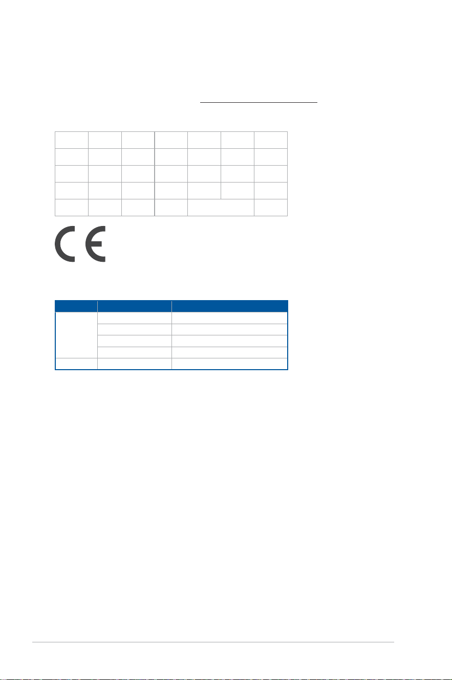
CE RED RF Output table
RTL8851BE
Function Frequency Maximum Output Power EIRP (mW)
WiFi
2.4 – 2.4835 GHz < 100
5.15 – 5.35 GHz < 200
5.47 – 5.725 GHz < 200
5.725 – 5.875 GHz** < 25
Bluetooth 2.4 – 2.4835 GHz < 100
* Receiver category 1
** Non-Intel modules: 5.725-5.85 GHz
Simplied EU Declaration of Conformity
ASUSTek Computer Inc. hereby declares that this device is in compliance with the essential
requirements and other relevant provisions of Directive 2014/53/EU. Full text of EU
declaration of conformity is available at https://www.asus.com/support/.
The Wi-Fi operating in the band 5150-5350MHz shall be restricted to indoor use for countries
listed in the table below:
AT BE BG CZ DK EE FR
DE IS IE IT EL ES CY
LV LI LT LU HU MT NL
NO PL PT RO SI SK TR
FI SE CH HR UK(NI)
'
11
Simplied UKCA Declaration of Conformity
ASUSTek Computer Inc. hereby declares that this device is in compliance with the essential
requirements and other relevant provisions of The Radio Equipment Regulations 2017 (S.I.
2017/1206). Full text of UKCA declaration of conformity is available at
https://www.asus.com/support/.
The Wi-Fi operating in the band 5150-5350MHz shall be restricted to indoor use for the
country listed below:
UK
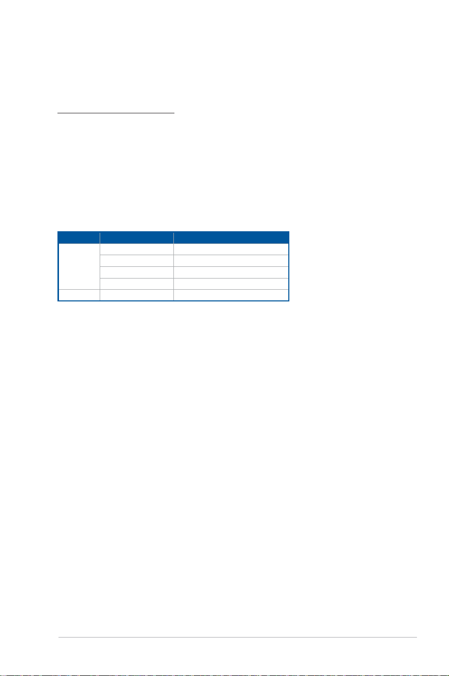
UKCA RF Output table
RTL8851BE
Function Frequency Maximum Output Power EIRP (mW)
WiFi
2.4 – 2.4835 GHz < 100
5.15 – 5.35 GHz < 200
5.47 – 5.725 GHz < 200
5.725 – 5.875 GHz** < 25
Bluetooth 2.4 – 2.4835 GHz < 100
* Receiver category 1
** Non-Intel modules: 5.725-5.85 GHz
12
FCC COMPLIANCE INFORMATION
Per FCC Part 2 Section 2.1077
Responsible Party:
Asus Computer International
Address:
48720 Kato Rd, Fremont
,
CA 94538.
Phone/Fax No: (510)739-3777/(510)608-4555
hereby declares that the product
Product Name :
Desktop PC
Model Number :
G700TF, G700TF_US
compliance statement:
This device complies with part 15 of the FCC Rules. Operation is subject to the
following two conditions: (1) This device may not cause harmful interference,
and (2) this device must accept any interference received, including interference
that may cause undesired operation.
Ver. 180620

13
Conventions used in this guide
To ensure that you perform certain tasks properly, take note of the following symbols used
throughout this manual.
DANGER/WARNING: Information to prevent injury to yourself when trying to
complete a task.
CAUTION: Information to prevent damage to the components when trying to
complete a task.
IMPORTANT: Instructions that you MUST follow to complete a task.
NOTE: Tips and additional information to help you complete a task.

14
Safety information
Disconnect the AC power and peripherals before cleaning. Wipe the Desktop PC using a
clean cellulose sponge or chamois cloth dampened with solution of nonabrasive detergent
and a few drops of warm water then remove any extra moisture with a dry cloth.
• DO NOT place on uneven or unstable work surfaces. Seek servicing if the casing has
been damaged.
• DO NOT expose to dirty or dusty environments. DO NOT operate during a gas leak.
• DO NOT place or drop objects on top and DO NOT shove any foreign objects into the
Desktop PC.
• DO NOT expose to strong magnetic or electrical elds.
• DO NOT expose to or use near liquids, rain, or moisture. DO NOT use the modem during
electrical storms.
• Battery safety warning: DO NOT throw the battery in re. DO NOT short circuit the
contacts. DO NOT disassemble the battery.
• Use this product in environments with ambient temperatures between 5°C (41°F) and
35°C (95°F).
• DO NOT cover the vents on the Desktop PC to prevent the system from getting
overheated.
• DO NOT use damaged power cords, accessories, or other peripherals.
• To prevent electrical shock hazard, disconnect the power cable from the electrical outlet
before relocating the system.
• Seek professional assistance before using an adapter or extension cord. These devices
could interrupt the grounding circuit.
• Ensure that your power supply is set to the correct voltage in your area. If you are not
sure about the voltage of the electrical outlet you are using, contact your local power
company.
• If the power supply is broken, DO NOT try to x it by yourself. Contact a qualied service
technician or your retailer.
• The Desktop PC is non-portable.
15
Hazardous moving parts. Desktop should be completely shutdown before servicing
product. Replacing fan components should only be attempted by qualied service
personnel.
WARNING: Keep ngers and other body parts away from any moving parts.
Hazardous Moving Parts Warning
CAUTION: DO NOT loosen the thumb screws to access the internal area of your device. If
service or repair is required, return your device to an authorized service center.
WARNING! Hot Internal replaceable parts and iron parts may cause burns.
Coating notice
IMPORTANT! To provide electrical insulation and maintain electrical safety, a coating is
applied to insulate the device except on the areas where the I/O ports are located.
“Do not ingest battery, Chemical Burn Hazard”
This product contains a coin / button cell battery. If the coin / button cell battery is
swallowed, it can cause severe internal burns in just 2 hours and can lead to death.
Keep new and used batteries away from children.
If the battery compartment does not close securely, stop using the product and keep it away
from children.
If you think batteries might have been swallowed or placed inside any part of the body, seek
immediate medical attention.

16
Where to nd more information
Refer to the following sources for additional information and for product and software
updates.
ASUS website
The ASUS website provides updated information on ASUS hardware and software
products. Refer to the ASUS website www.asus.com.
ASUS Local Technical Support
Visit ASUS website at https://www.asus.com/support/contact for the contact
information of local Technical Support Engineer.
Tutorial
Tool-less: G700TF/G700TF_US is tool-less design. You can disassemble the chassis by
removing knurled thumb screws by hand, and replace hard disc drive and optical disc
drive easily.
After replacement, please assemble G700TF/G700TF_US back to the original state. For
more replacement and assembly information, please refer link as below:
https://www.youtube.com/watch?v=1KH_hYfbIOo
17
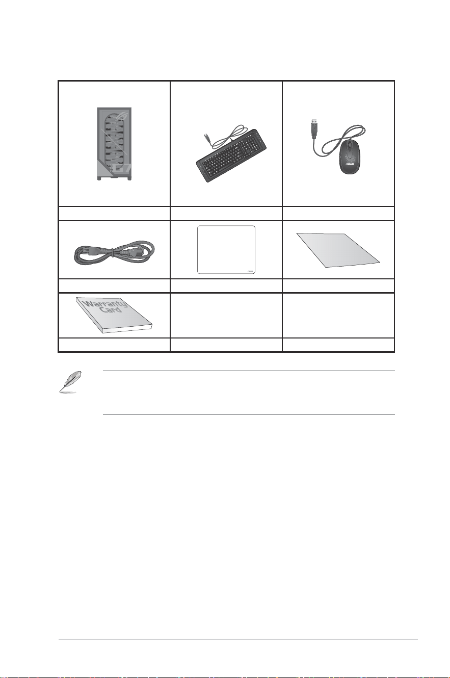
Package contents
ASUS Desktop PC Keyboard x1 (Optional) Mouse x1 (Optional)
Installation Guide
Power cord x1 ASUS mouse pad x 1 (Optional) Installation Guide x1
Warranty card x1
• If any of the above items is damaged or missing, contact your retailer.
• The illustrated items above are for reference only. Actual product specications may
vary with different models.

18

ASUS Desktop PC
19
Chapter 1
Getting started
Welcome!
Thank you for purchasing the ASUS Desktop PC!
The ASUS Desktop PC provides cutting-edge performance, uncompromised reliability, and
user-centric utilities. All these values are encapsulated in a stunningly futuristic and stylish
system casing.
Read the ASUS Warranty Card before setting up your ASUS Desktop PC.
• The Desktop PC does not support Windows
®
7 operating system. ASUS is not
responsible for any loss or damage incurred by installing Windows
®
7.
• Be careful when handling the desktop PC to prevent the risk of injury.
Getting to know your computer
Illustrations are for reference only. The ports and their locations, and the chassis color vary
with different models.
IMPORTANT! Do not use this Desktop PC for cryptocurrency mining (consuming a vast
amount of electricity and time to gain convertible virtual currency) and/or related activities.
Chapter 1 Getting started
20
Chapter 1: Getting started
ENGLISH
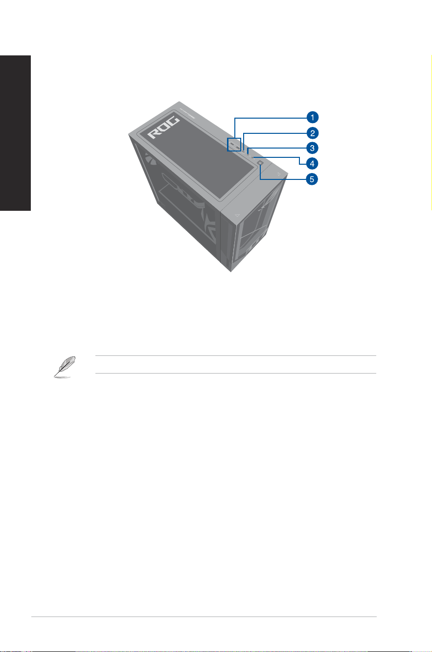
G700TF/G700TF_US Top panel
1. USB 3.2 Gen 1 ports. The Universal Serial Bus 3.2 Gen 1 (USB 3.2 Gen 1) ports connect
to USB 3.2 Gen 1 devices such as a mouse, printer, scanner, camera, PDA, and others.
2. USB 3.2 Gen 1 Type-C
®
port. The Universal Serial Bus 3.2 Gen 1 (USB 3.2 Gen 1)
Type-C
®
port connects to USB 3.2 Gen 1 Type-C
®
devices.
The output voltage of the USB 3.2 Gen 1 Type-C
®
ports is 5V, 3A.
3. Microphone port. This port connects to a microphone.
4. Headphone port. This port connects to a headphone or speaker.
5. Power button. Press this button to turn on your computer.
ASUS Desktop PC
21
ENGLISH
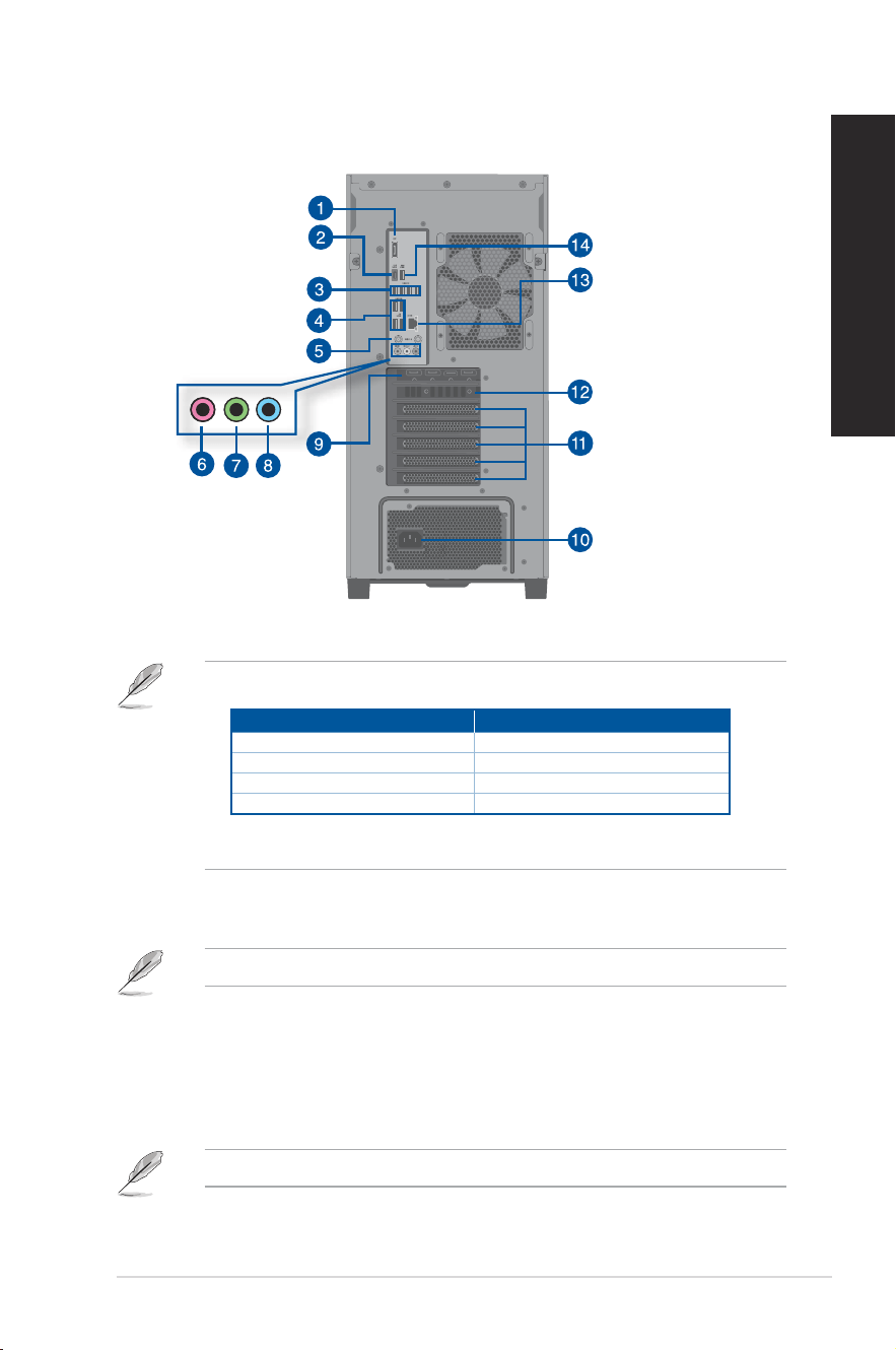
G700TF/G700TF_US Rear panel
1. DisplayPort. This port is for a DisplayPort-compatible device.
• The on-board DisplayPort only works while using a CPU with integrated graphics.
DisplayPort
Intel
®
Core™ Ultra 9 Processor 285K Support
Intel
®
Core™ Ultra 7 Processor 265KF Not support
Intel
®
Core™ Ultra 7 Processor 265F Not support
Intel
®
Core™ Ultra 5 Processor 225F Not support
• If there is an external graphics card on your computer, please connect your monitor to
the display output port on it.
2. USB 3.2 Gen 2x2 Type-C
®
port. The Universal Serial Bus 3.2 Gen 2x2 (USB 3.2 Gen 2x2)
Type-C
®
port connects to USB 3.2 Gen 2x2 Type-C
®
devices.
The output voltage of the USB 3.2 Gen 2x2 Type-C
®
port is 5V, 3A.
3. USB 2.0 ports. These Universal Serial Bus 2.0 (USB 2.0) ports connect to USB 2.0
devices such as a mouse, printer, scanner, camera, PDA, and others.
4. USB 3.2 Gen 1 ports. These 9-pin Universal Serial Bus (USB) ports connect to USB 3.2
Gen 1 devices.
5. Wi-Fi 6 ports. These ports connect to Wi-Fi antennas.
Refer to the section Wi-Fi moving antenna installation in Chapter 4 for details.
22
Chapter 1: Getting started
ENGLISH
6. Microphone port (pink). This port connects to a microphone.
7. Line Out port (lime). This port connects to a headphone or speaker. In a 4, 5.1, or
7.1-channel conguration, the function of this port becomes Front Speaker Out.
8. Line In port (light blue). This port connects to a tape, CD, DVD player, or other audio
sources.
Refer to the audio conguration table below for the function of the audio ports in the 2, 4,
5.1, or 7.1-channel conguration.
Audio 2, 4, 5.1, or 7.1-channel conguration
Port
Headset
2-channel
4-channel 5.1-channel 7.1-channel
Light Blue (Rear panel) Line In Rear Speaker Out Rear Speaker Out Rear Speaker Out
Lime (Rear panel) Line Out Front Speaker Out Front Speaker Out Front Speaker Out
Pink (Rear panel) Mic In Mic In Bass/Center Bass/Center
Microphone (Top panel) - - - Side Speaker Out
9. ASUS Graphics Card (on selected models only). The display output ports on this
optional ASUS Graphics Card may vary with different models.
10. Power connector. Plug the power cord to this connector.
RATING:
• 115/230Vac, 50/60Hz, 6A/3A (Global);
220Vac 50Hz, 3A (Chinese Mainland);
115Vac, 60Hz, 6A (Taiwan);
115/230Vac, 50/60Hz, 6A/3A (Japan; Korea)
• 115/230Vac, 50/60Hz, 10A/5A (Global);
220Vac 50Hz, 5A (Chinese Mainland);
115Vac, 60Hz, 10A (Taiwan);
115/230Vac, 50/60Hz, 10A/5A (Japan; Korea)
11. Air vents. These vents allow air ventilation.
DO NOT block the air vents on the chassis. Always provide proper ventilation for your
computer.
ASUS Desktop PC
23
ENGLISH
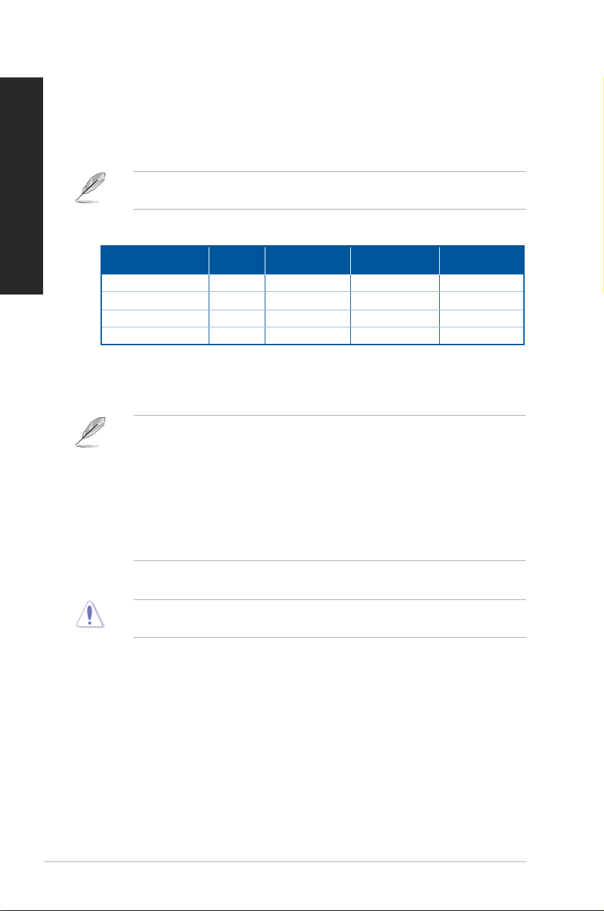
12. Expansion slot bracket. Remove the expansion slot bracket when installing an
expansion card.
• PCIEX16_1 slot supports graphics cards and storage devices only while other PCIE slots
support storage devices and other PCIe devices.
• Install the primary graphics card in PCIEX16_1 if you use two graphics cards.
PCIEX1_1
PCIEX16_2
PCIEX1_2
PCIEX16_1
• ASUS Graphics Card is available on selected models. The display output ports on the
optional ASUS Graphics Card may vary with different models.
• Refer to Installing a graphics card in your computer for detailed instructions.
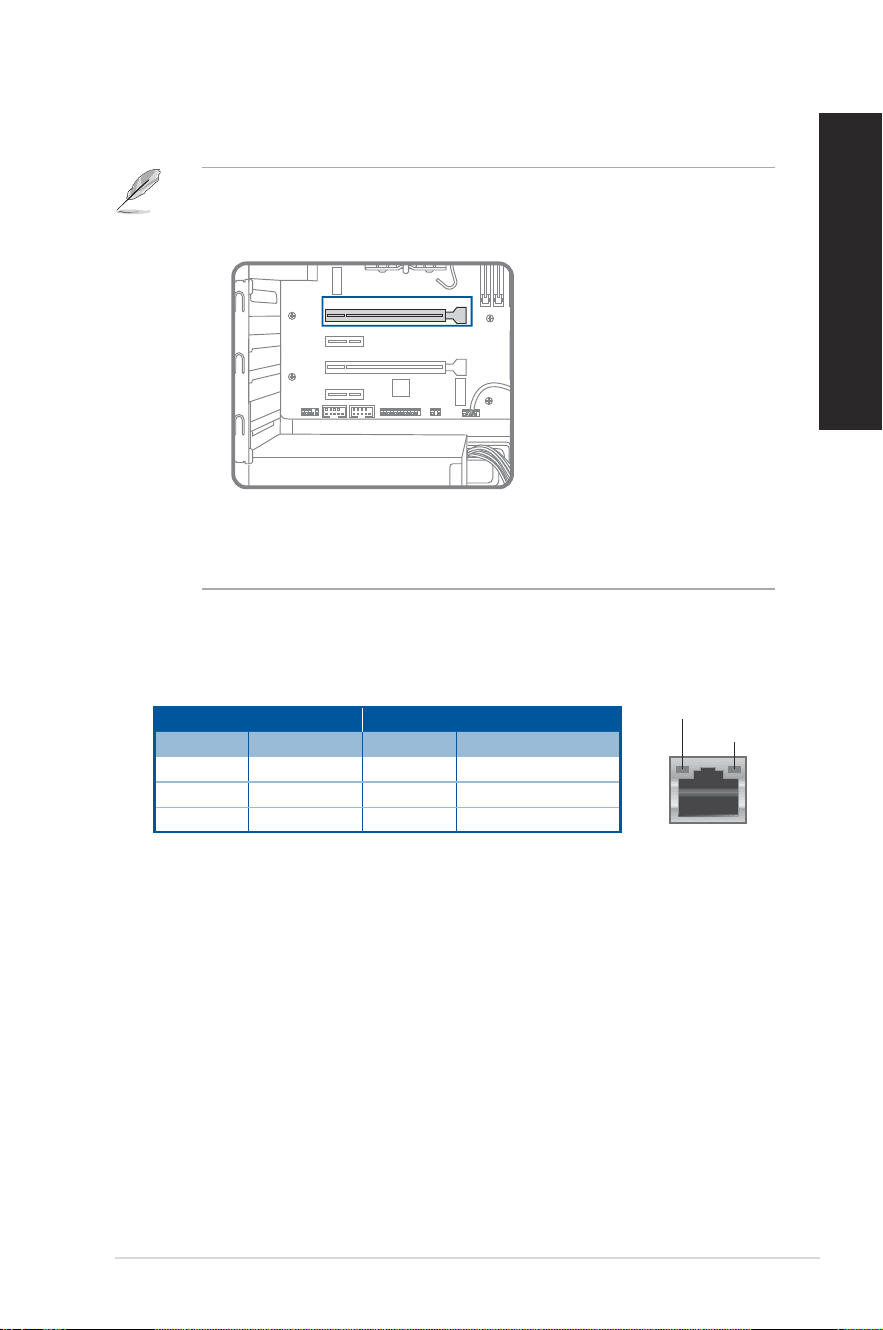
13. LAN (RJ-45) port. This port allows Gigabit connection to a Local Area Network (LAN)
through a network hub.
LAN port LED indications
ACT/LINK
LED
LAN port
SPEED LED
Activity/Link LED Speed LED
Status Description Status Description
OFF No link OFF 10Mbps connection
ORANGE Linked ORANGE 100Mbps connection
BLINKING Data activity GREEN 1Gbps connection
14. USB 3.2 Gen 2 port. This 9-pin Universal Serial Bus (USB) ports connects to USB 3.2
Gen 2 devices.
24
Chapter 1: Getting started
ENGLISH
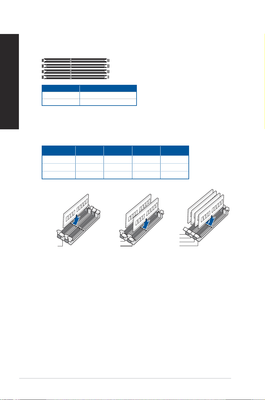
Installing memory in your computer
This desktop PC comes with four Double Data Rate 5 (DDR5) Dual Inline Memory Module
(DIMM) sockets. The gure illustrates the location of the DDR5 DIMM sockets.
DIMM_B2
DIMM_B1
DIMM_A2
DIMM_A1
Channel Sockets
Channel A DIMM_A1 & DIMM_A2
Channel B DIMM_B1 & DIMM_B2
Recommended memory congurations
• Follow the installation sequence below to ensure system stability and avoid possible
booting up failure.
DIMM_A1 DIMM_A2 DIMM_B1 DIMM_B2
1 x DIMM x √ x x
2 x DIMM x √ x √
4 x DIMM √ √ √ √
DIMM_B2
DIMM_A2
DIMM_A2
DIMM_A1
DIMM_A2
DIMM_B1
DIMM_B2
ASUS Desktop PC
25
ENGLISH
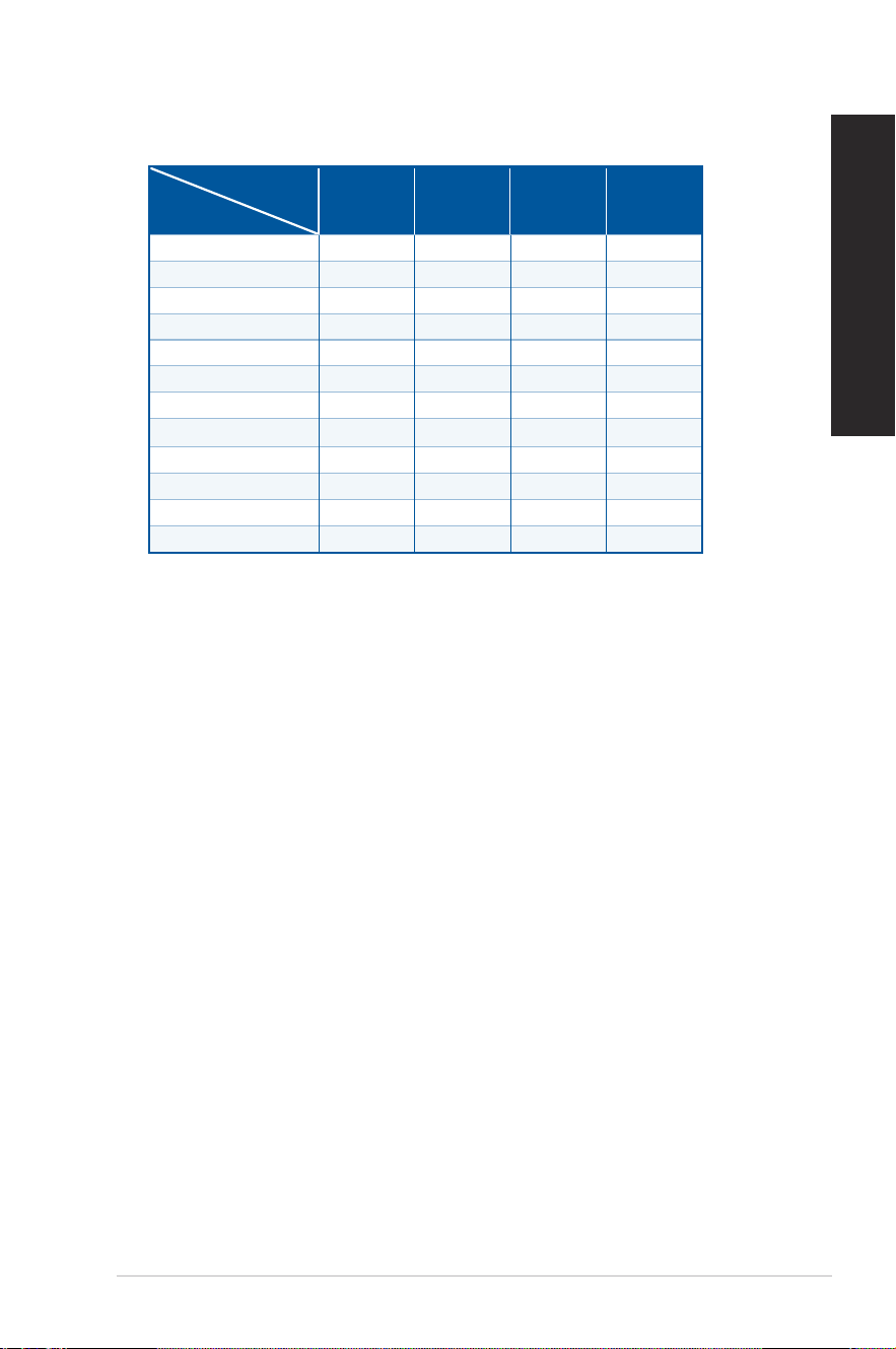
• Install DIMMs with the same capacity from the same manufacturer in the slots of the
same channel.
Total
memory capacity
DIMM_A1 DIMM_A2 DIMM_B1 DIMM_B2
4GB 4GB
8GB 8GB
8GB 4GB 4GB
16GB 16GB
16GB 8GB 8GB
16GB 4GB 4GB 4GB 4GB
32GB 32GB
32GB 16GB 16GB
32GB 8GB 8GB 8GB 8GB
64GB 32GB 32GB
64GB 16GB 16GB 16GB 16GB
128GB 32GB 32GB 32GB 32GB
Single memory
capacity
26
Chapter 1: Getting started
ENGLISH
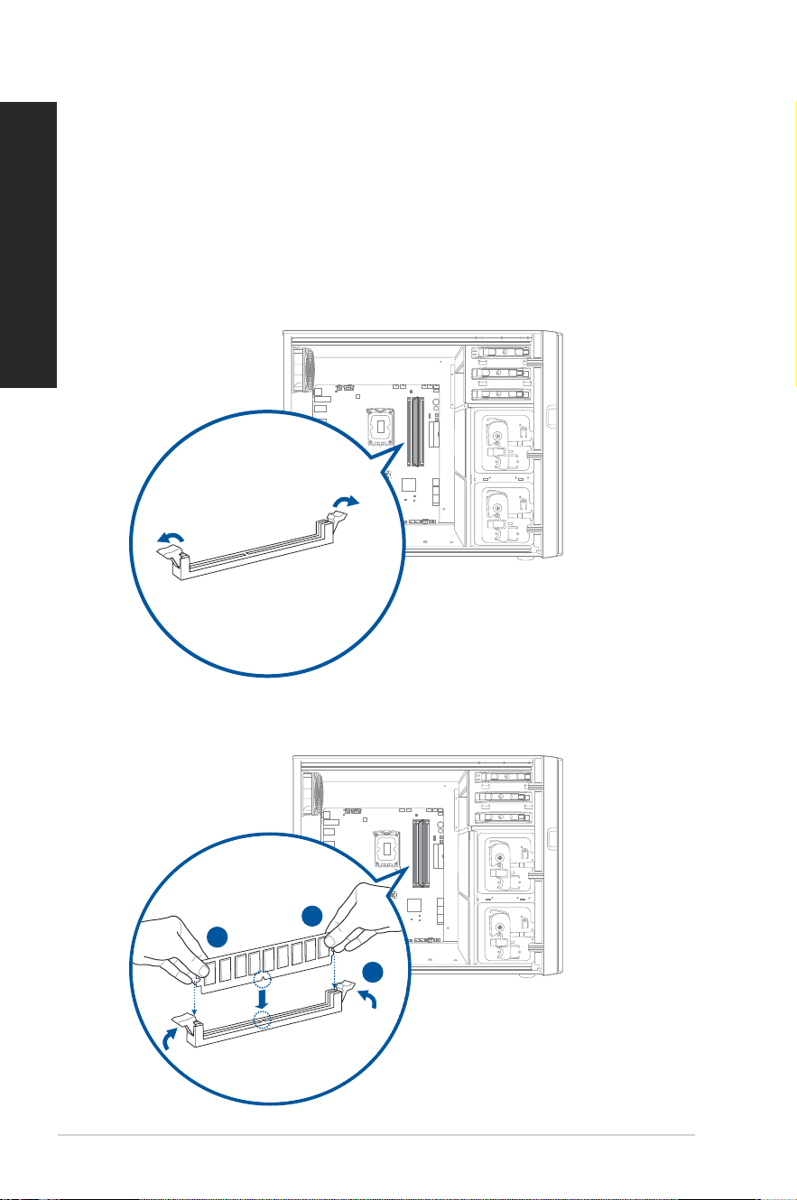
Installing memory in your computer
To install memory in your computer:
1. Turn off your computer.
2. Unplug all cables from your computer.
3. Open your computer case.
4. Remove the graphics card.
5. Locate an empty DIMM socket.
6. Press down and outward on the DIMM ejector(s) to unlock the DIMM socket.
START
RESET
7. Align the notch on the bottom edge of the DIMM with the key of the DIMM socket, and
then rmly insert the DIMM into the socket until the ejector(s) snap(s) back into place.
START
RESET
A
A
B

ASUS Desktop PC
27
ENGLISH
8. Install the graphics card.
9. Close your computer case.
The above pictures are for reference only. The inner structure of the desktop PC may vary.

28
Chapter 1: Getting started
ENGLISH
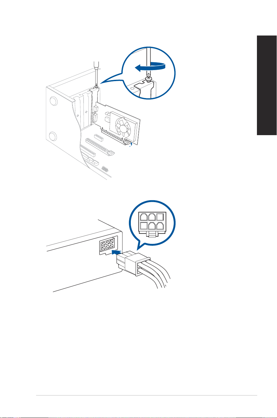
Installing a graphics card in your computer
To install a graphics card in your computer:
1. Turn off your computer.
2. Unplug all cables from your computer.
3. Open your computer case and locate PCIEX16_1 slot if you are installing the rst or the
primary graphics card.
4. Align the notch on your graphics card with the key of the slot, and then insert the card
into the slot.
5. The ejector will snap back into place automatically.
ASUS Desktop PC
29
ENGLISH
6. Use a screw driver and a screw to lock the graphics card on the chassis.
7. (Optional) Connect a proper power supply plug to the graphics card.
30
Chapter 1: Getting started
ENGLISH
Setting up your computer
This section guides you through connecting the main hardware devices, such as the external
monitor, keyboard, mouse, and power cord, to your computer.
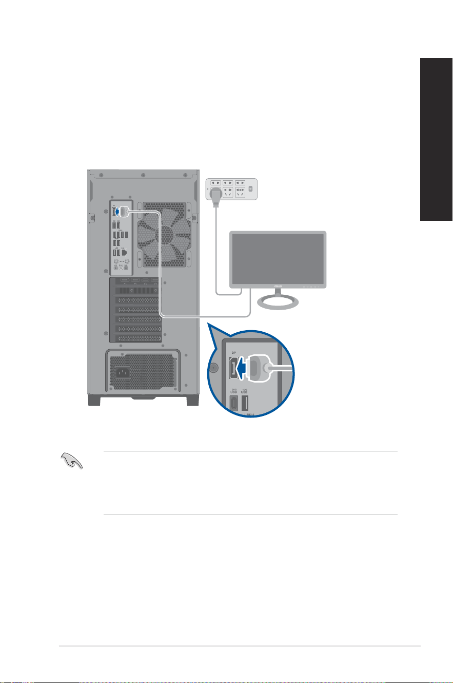
Connecting an external monitor
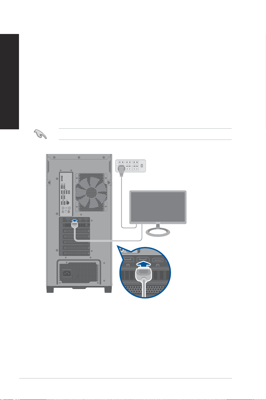
Using the ASUS Graphics Card (on selected models only)
Connect your monitor to the display output port on the discrete ASUS Graphics Card.
To connect an external monitor using the ASUS Graphics Card:
1. Connect a monitor to a display output port on the ASUS Graphics Card.
2. Plug the monitor to a power source.
The display output ports on the ASUS Graphics Card may vary with different models.
ASUS Desktop PC
31
ENGLISH
Using the onboard display output ports
Connect your monitor to the onboard display output port.
To connect an external monitor using the onboard display output ports:
1. Connect a monitor to a display output port on the rear panel of your computer.
2. Plug the monitor to a power source.
• If your computer comes with an ASUS Graphics Card, the graphics card is set as the
primary display device in the BIOS. Hence, connect your monitor to a display output port
on the graphics card.
• To connect multiple external monitors to your computer, refer to Connecting multiple
external displays in Chapter 2 of this guide for details.
32
Chapter 1: Getting started
ENGLISH
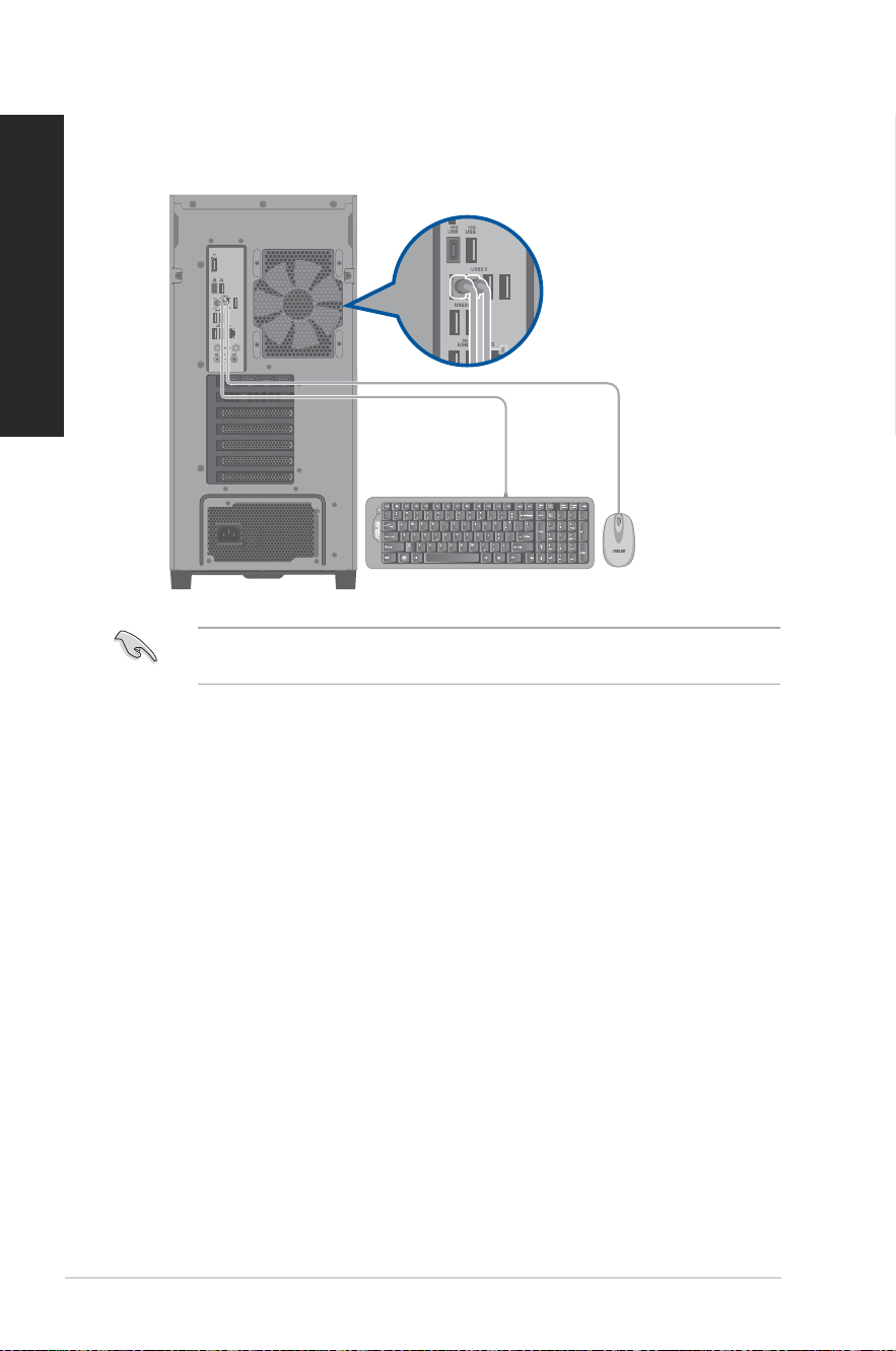
Connecting a USB keyboard and a USB mouse
Connect a USB keyboard and a USB mouse to the USB ports on the rear panel of your
computer.
Connect your keyboard and mouse to the USB 2.0 ports to maximize the availability of the
remaining high-speed USB ports for devices requiring faster data transfer.
ASUS Desktop PC
33
ENGLISH
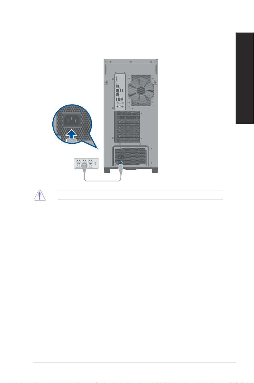
Connecting the power cord
Connect one end of the power cord to the power connector on the rear panel of your
computer and the other end to a power source.
For safety purpose, ONLY connect the power cord to a grounded electrical outlet.
34
Chapter 1: Getting started
ENGLISH
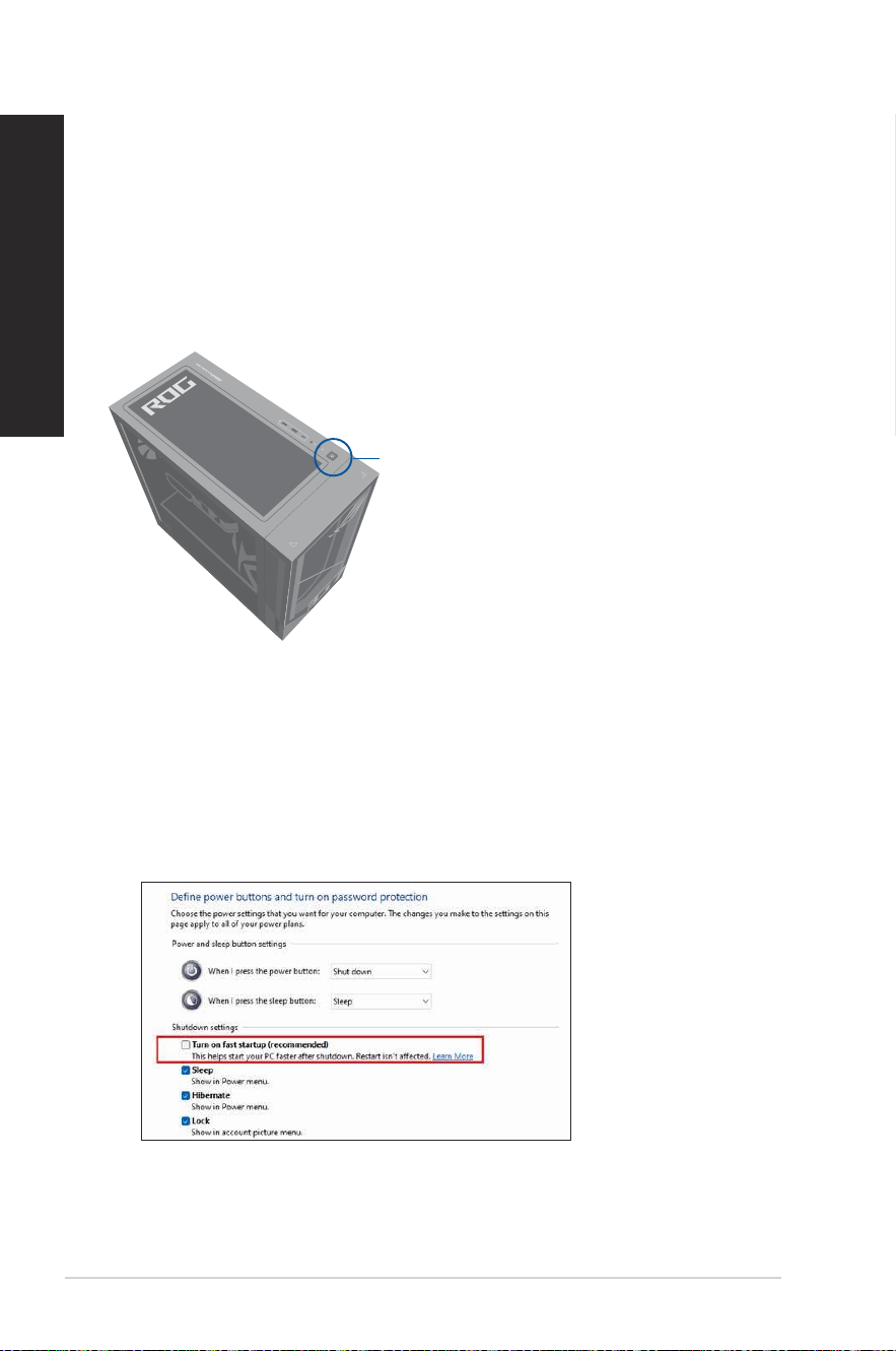
Turning your computer ON
This section describes how to turn on your computer after setting up your computer.
Turning your computer ON
To turn your computer ON:
1. Turn your monitor ON.
2. Press the power button on your computer.
3. Wait until the operating system loads automatically.
Enabling fast startup
You can shut down the computer with fast startup enabled.
To enable fast startup in Shutdown settings:
Enter Control Panel in the search bar and open it (View by: Category), select Hardware and
Sound > Power Options > Choose what the power button does, click Change settings that are
currently unavailable, check Turn on fast startup (recommended) and click Save changes.
If fast startup is disabled, when you shut down the computer, it shuts down to the S5 power
state.
Power button
ASUS Desktop PC
35
Chapter 2
Connecting devices to your computer
Top panel Rear panel
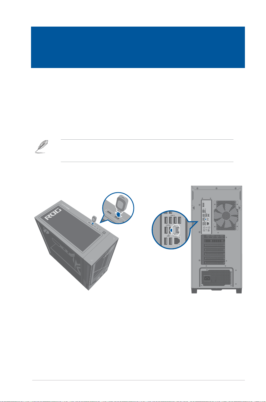
Connecting a USB storage device
This desktop PC provides USB 3.2 Gen 2, USB 3.2 Gen 2x2 Type-C
®
, USB 3.2 Gen 1 and USB
2.0 ports on the front and rear panels. The USB ports allow you to connect USB devices such
as storage devices.
To connect a USB storage device:
• Insert the USB storage device to your computer.
You can enable or disable the front and rear USB 3.2 Gen 2, USB 3.2 Gen 2x2 Type-C
®
, USB
3.2 Gen 1 and USB 2.0 ports individually from the BIOS Setup. Refer to the Conguring the
USB ports using the BIOS section in Chapter 3 of this user manual for details.
Chapter 2 Connecting devices to your computer
36
Chapter 2: Connecting devices to your computer
ENGLISH
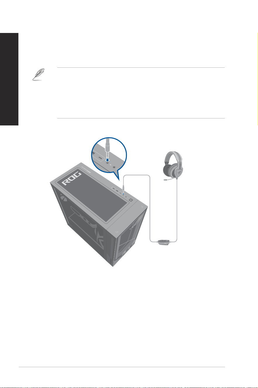
Connecting microphone and speakers
This desktop PC comes with microphone ports and speaker ports on both the front and
rear panels. The audio I/O ports located on the rear panel allow you to connect 2-channel,
4-channel, 5.1-channel, and 7.1-channel stereo speakers.
• When your Desktop PC comes with an internal speaker, the audio output will be from the
internal speaker.
• When you connect an external audio device such as earphone or speaker, you need to
enable the audio device output. For details, refer to the section Changing to the external
audio output.
• When you disconnect the audio device, you need to manually change the audio output to
the internal speaker from the Control Panel.
Connecting Headphone and Mic
ASUS Desktop PC
37
ENGLISH
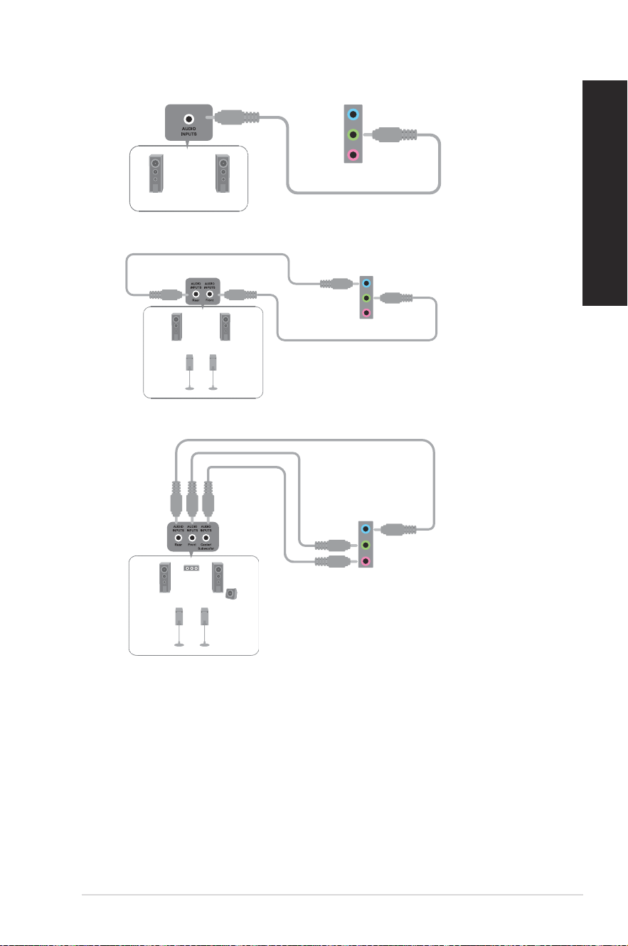
Connecting 2-channel Speakers
Connecting 4-channel Speakers
Connecting 5.1-channel Speakers
38
Chapter 2: Connecting devices to your computer
ENGLISH
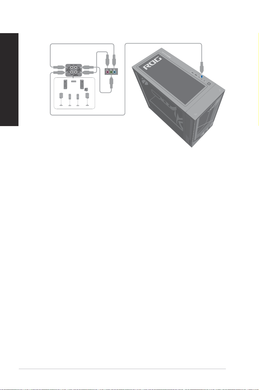
Connecting 7.1-channel Speakers
ASUS Desktop PC
39
ENGLISH
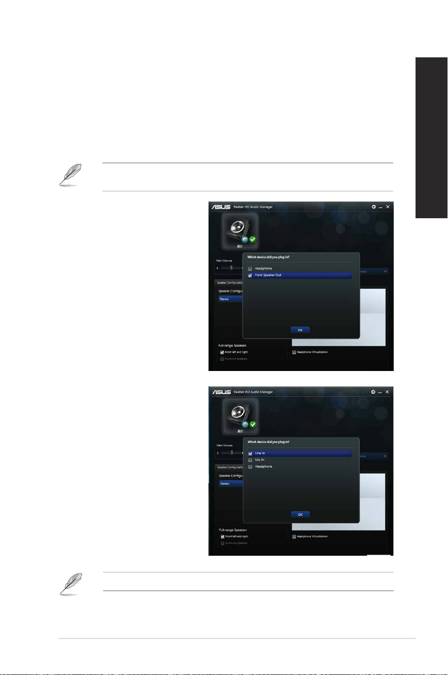
Changing to the external audio output
When you connect an external audio device to your Desktop PC, enable the audio device
output to ensure a clear audio quality.
To change to the external audio output:
1. Connect an external audio device such as earphone or speaker to the rear Line Out port.
The Audio Manager screen automatically pops up.
For the location of the rear Line Out port, refer to the section Getting to know your
computer.
2. Tick Front Speaker Out, then click
OK.
3. Tick Line In, then click OK. The
audio output will now be from the
external audio device.
The Audio Manager screenshots above are for reference only.
40
Chapter 2: Connecting devices to your computer
ENGLISH
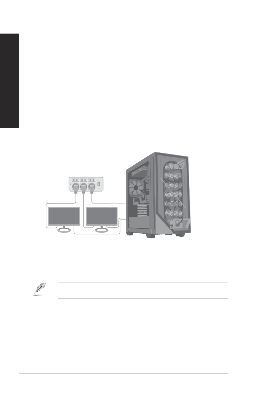
Connecting multiple external displays
Your desktop PC may come with VGA, HDMI™, or DVI ports and allows you to connect
multiple external displays.
Setting up multiple displays
When using multiple monitors, you are allowed to set display modes. You can use the
additional monitor as a duplicate of your main display, or as an extension to enlarge your
Windows
®
desktop.
To set up multiple displays:
1. Turn off your computer.
2. Connect the two monitors to your computer and connect the power cords to the
monitors. Refer to Setting up your computer section in Chapter 1 for details on how to
connect a monitor to your computer.
3. Turn on your computer.
4. From the Start menu, click Settings > System > Display.
5. Congure the settings for your displays.
For some graphics cards, only the monitor that is set to be the primary display has display
during POST. The dual display function works only under Windows.
ASUS Desktop PC
41
Chapter 3
Using your computer
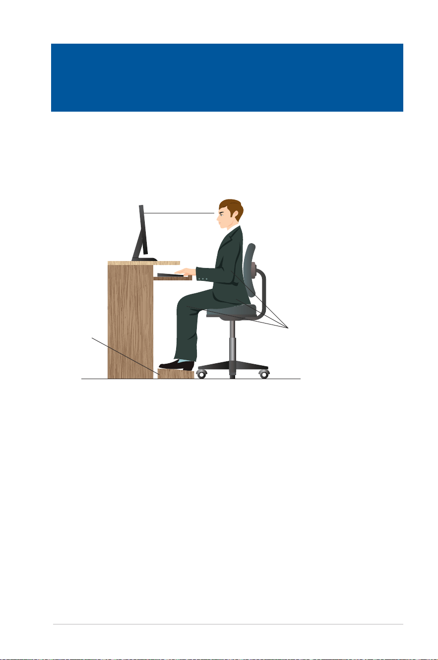
Proper posture when using your Desktop PC
When using your Desktop PC, maintaining the proper posture is necessary to prevent strain to
your wrists, hands, and other joints or muscles. This section provides you with tips on avoiding
physical discomfort and possible injury while using and fully enjoying your Desktop PC.
Eye level to the top of
the monitor screen
Foot rest 90˚ angles
To maintain the proper posture:
• Position your computer chair to make sure that your elbows are at or slightly above the
keyboard to get a comfortable typing position.
• Adjust the height of your chair to make sure that your knees are slightly higher than your
hips to relax the backs of your thighs. If necessary, use a footrest to raise the level of your
knees.
• Adjust the back of your chair so that the base of your spine is rmly supported and angled
slightly backward.
• Sit upright with your knees, elbows and hips at an approximately 90º angle when you are
at the PC.
• Place the monitor directly in front of you, and turn the top of the monitor screen even with
your eye level so that your eyes look slightly downward.
• Keep the mouse close to the keyboard, and if necessary, use a wrist rest for support to
reduce the pressure on your wrists while typing.
• Use your Desktop PC in a comfortably-lit area, and keep it away from sources of glare
such as windows and straight sunlight.
• Take regular mini-breaks from using your Desktop PC.
Chapter 3 Using your computer
42
Chapter 3: Using your computer
ENGLISH
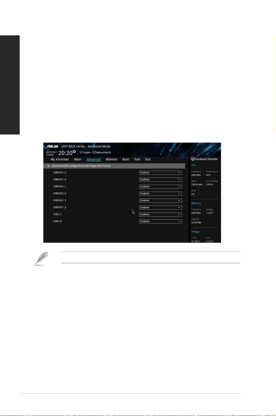
Conguring the USB ports using the BIOS
You can enable or disable the USB 3.2 Gen 2, USB 3.2 Gen 2x2 Type-C
®
, USB 3.2 Gen 1 and
USB 2.0 ports from the BIOS Setup.
To disable or enable the USB 3.2 Gen 2, USB 3.2 Gen 2x2 Type-C
®
, USB 3.2 Gen 1 and USB
2.0 ports:
1. Press <Delete> to enter the BIOS Setup at startup.
2. From the BIOS Setup EZ Mode screen, press <F7> to enter the Advanced Mode. From
the Advanced Mode screen, click Advanced > USB Conguration > USB Single Port
Control.
3. Select the USB port that you want to enable or disable.
4. Press <Enter> to enable or disable the selected USB port.
5. Click Exit and select Save Changes & Reset to save the changes made.
Refer to Chapter 1 for the location of the USB ports.
ASUS Desktop PC
43
ENGLISH
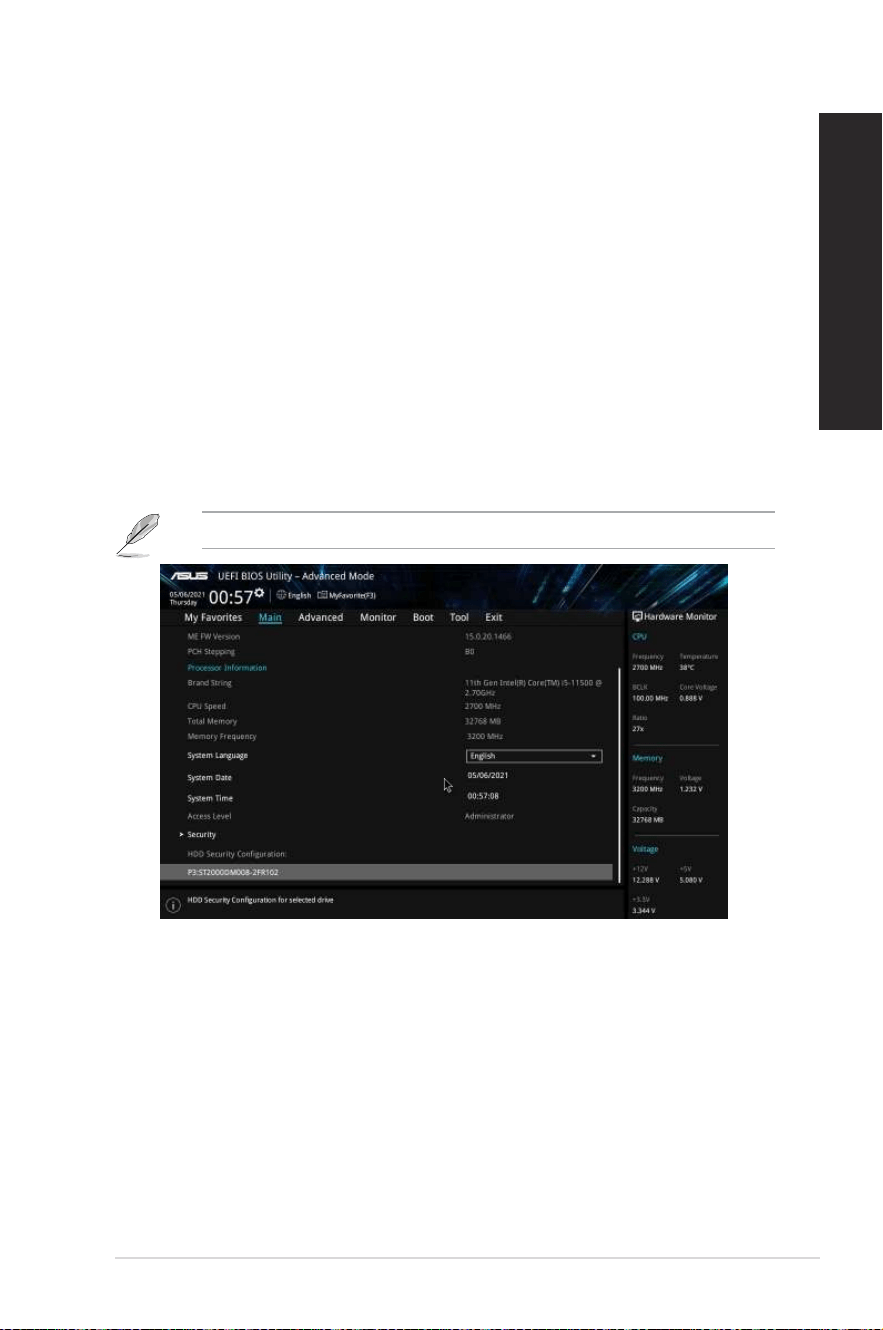
Conguring the HDD security setting using the BIOS
You can set a password in the BIOS Setup to protect your HDD.
To set a password for your HDD from the BIOS Setup:
1. Press <Delete> to enter the BIOS Setup at startup.
2. From the BIOS Setup EZ Mode screen, press <F7> to enter the Advanced Mode.
From the Advanced Mode screen, click Main and the selected HDD to open the HDD
Password screen.
3. Select the Set Master Password item and press <Enter>.
4. From the Create New Password box, key in a password, then press <Enter>.
5. Conrm the password when prompted.
6. Select the Set User Password item and press <Enter>.
7. Follow steps 4 and 5 to set the user password.
8. Click Exit and select Save Changes & Reset to save the changes made.
Take note of this password, which you would need to access the HDD.
To change the password for your HDD from the BIOS Setup:
1. Follow steps 1 and 2 of the previous section to open the HDD Password screen.
2. Select the Set Master Password item and press <Enter>.
3. From the Enter Current Password box, key in the current password, then press <Enter>.
4. From the Create New Password box, key in a new password, then press <Enter>.
5. Conrm the password when prompted.
6. Click Exit and select Save Changes & Reset to save the changes made.
To clear the user password, follow the same steps as in changing a user password, but press
<Enter> when prompted to create/conrm the password. After you clear the password, the
Set User Password item on top of the screen shows Not Installed.

44
Chapter 5: Using ASUS Business Manager
ENGLISH
Conguring the Keyboard/Mouse using the BIOS (on
selected models only)
You can wake up your computer with a keyboard or mouse. You can enable the feature from
the BIOS Setup.
To allow a keyboard or mouse to wake up your computer:
1. Restart your computer. When the ASUS logo appears, press <Delete> to enter the BIOS
Setup.
2. From the BIOS Setup EZ Mode screen, press <F7> to enter Advanced Mode. From the
Advanced Mode screen, click Advanced.
3. Go to Advanced Power Management > ErP Support / ErP Ready, then select Disable or
Enable (S5).
4. Go to Advanced Power Management > Power On By USB Keyboard/Mouse, then select
Enable.
5. Click Exit and select Save Changes & Reset to save the changes made.
ASUS Desktop PC
45
Chapter 4
Connecting to the Internet
Chapter 4 Connecting to the Internet
Wired connection
Use an RJ-45 cable to connect your computer to a DSL/cable modem or a local area network
(LAN).
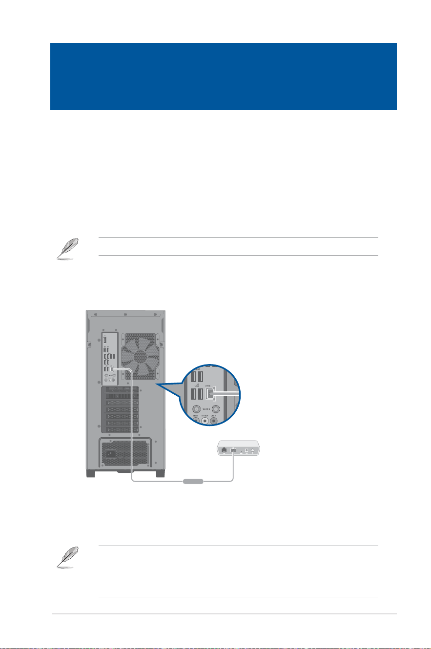
Connecting via a DSL/cable modem
To connect via a DSL/cable modem:
1. Set up your DSL/cable modem.
Refer to the documentation that came with your DSL/cable modem.
2. Connect one end of an RJ-45 cable to the LAN (RJ-45) port on the rear panel of your
computer and the other end to a DSL/cable modem.
3. Turn on the DSL/cable modem and your computer.
4. Congure the necessary Internet connection settings.
• Contact your network administrator for details or assistance in setting up your Internet
connection.
• For more details, refer to the sections Conguring a dynamic IP/PPPoE network
connection or Conguring a static IP network connection.
Modem
RJ-45 cable
46
Chapter 4: Connecting to the Internet
ENGLISH
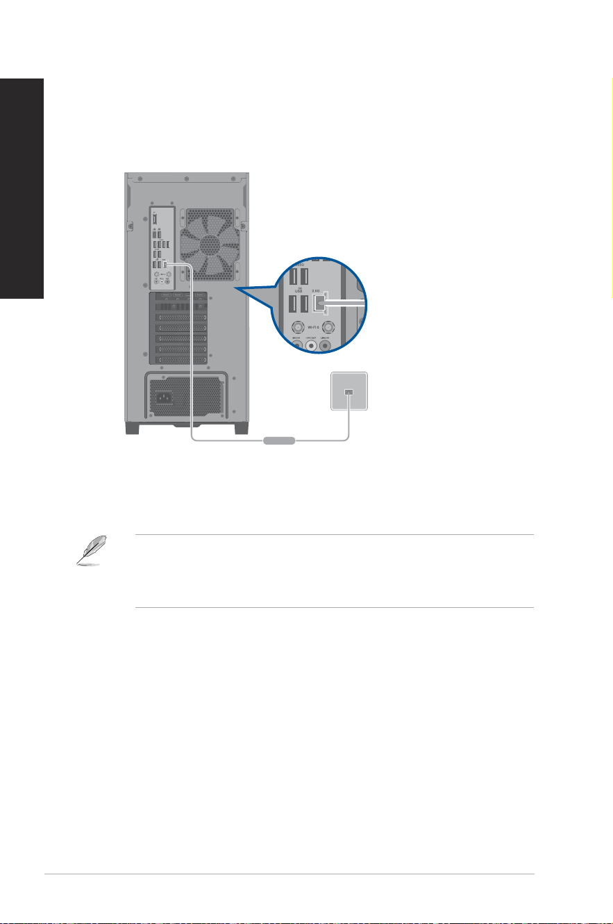
Connecting via a local area network (LAN)
To connect via a LAN:
1. Connect one end of an RJ-45 cable to the LAN (RJ-45) port on the rear panel of your
computer and the other end to your LAN.
2. Turn on your computer.
3. Congure the necessary Internet connection settings.
• Contact your network administrator for details or assistance in setting up your Internet
connection.
• For more details, refer to the sections Conguring a dynamic IP/PPPoE network
connection or Conguring a static IP network connection.
LAN
RJ-45 cable
ASUS Desktop PC
47
ENGLISH
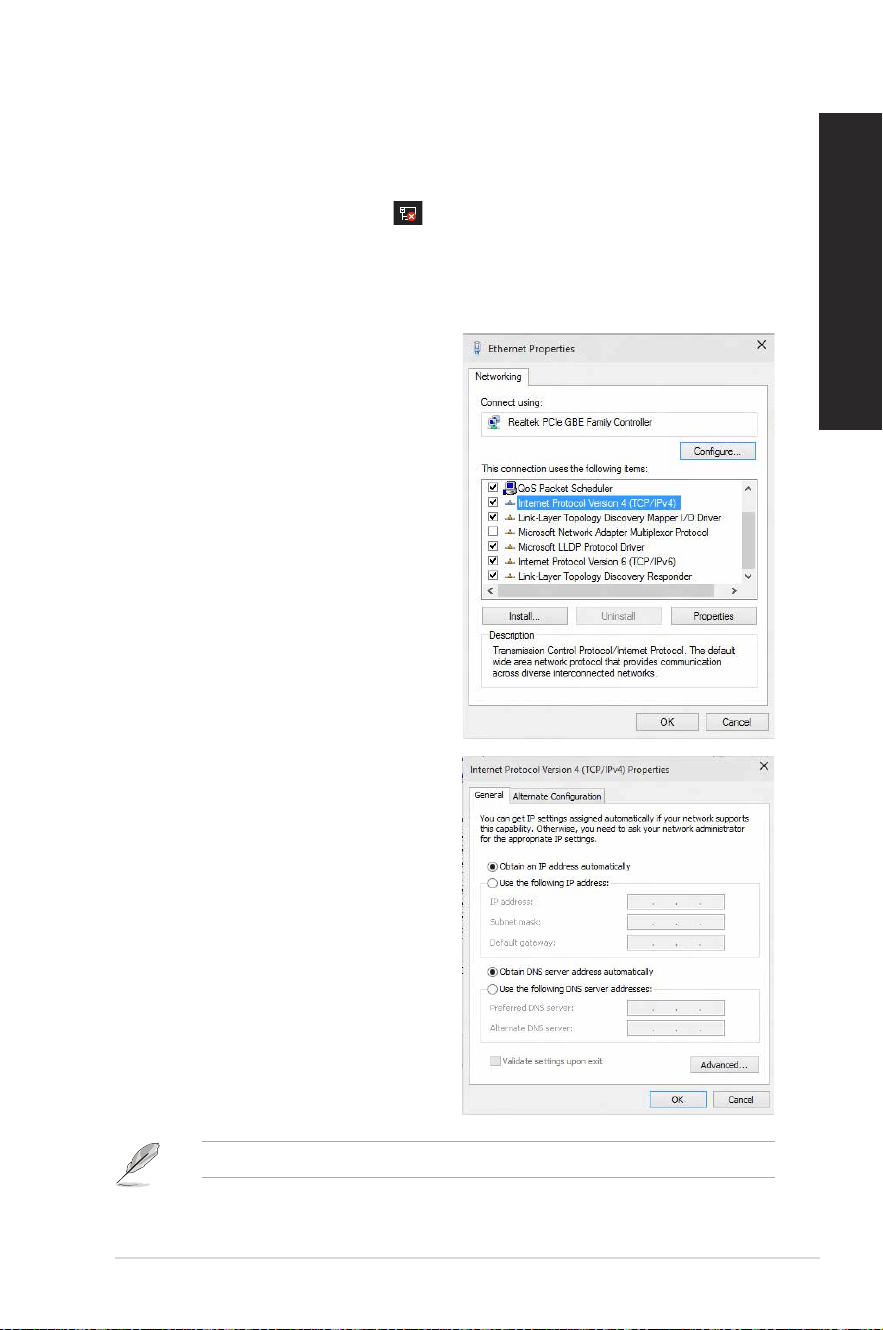
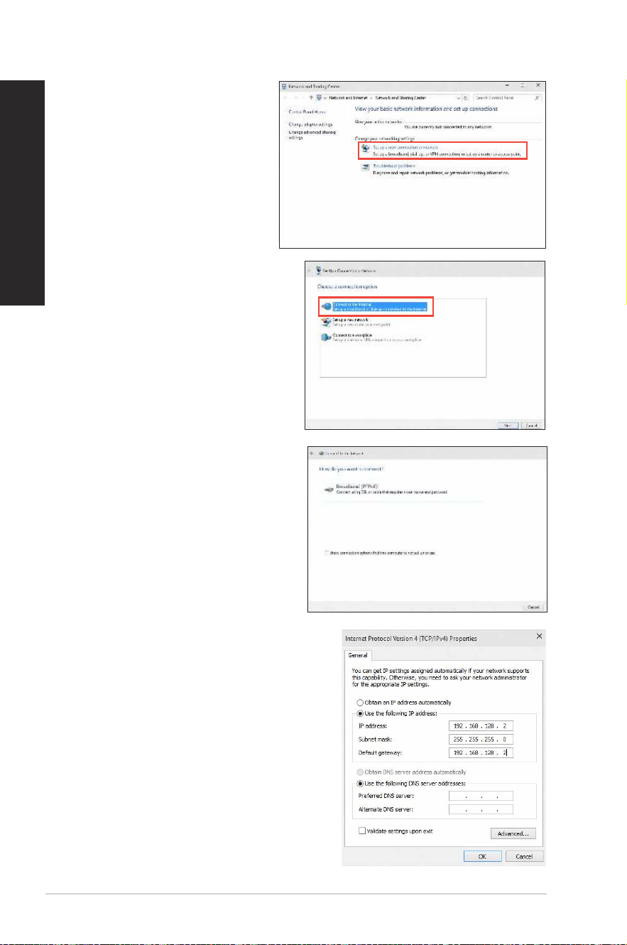
Conguring a dynamic IP/PPPoE network connection
To congure a dynamic IP/PPPoE network connection:
1. Launch Network and Sharing Center in either of these two ways:
a) From the taskbar, right-click
, then click Open Network and Sharing Center.
b) From the Start menu, click Settings > Network & Internet > Ethernet > Network
and Sharing Center.
2. From the Open Network and Sharing Center screen, click Change Adapter settings.
3. Right-click on your LAN and select
Properties.
4. Click Internet Protocol Version 4(TCP/
IPv4) and click Properties.
5. Click Obtain an IP address automatically
and click OK.
Continue to the next steps if you are using PPPoE connection.
48
Chapter 4: Connecting to the Internet
ENGLISH
7. Select Connect to the Internet and
click Next.
6. Return to the Network and
Sharing Center and then click
Set up a new connection or
network.
8. Select Broadband (PPPoE) and click
Next.
9. Follow the next onscreen instructions
to complete the setup.
Conguring a static IP network
connection
To congure a static IP network connection:
1. Repeat steps 1 to 4 of the previous section.
2 Click Use the following IP address.
3. Enter the IP address, Subnet mask and
Gateway from your service provider.
4. If needed, enter the preferred DNS Server
address and alternative address.
5. When done, click OK.
ASUS Desktop PC
49
ENGLISH
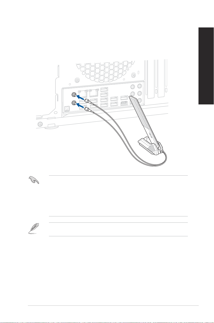
Wi-Fi moving antenna installation
Installing the ASUS Wi-Fi moving antenna
Connect the bundled ASUS Wi-Fi moving antenna connector to the Wi-Fi ports at the back of
the chassis.
• Ensure that the ASUS Wi-Fi moving antenna is securely installed to the Wi-Fi ports on the
ASUS network card.
• Ensure that the antenna is at least 20 cm away from all persons.
• Place the antenna on the top of your desktop PC for the best wireless performance.
• If your desktop PC comes with a 1x1 network card, the ASUS 2x2 dual band Wi-Fi
antenna connected to this network card will operate in 1x1 mode.
The illustration above is for reference only. The I/O port layout may vary with models, but
the Wi-Fi moving antenna installation procedure is the same for all models.

50
Chapter 4: Connecting to the Internet
ENGLISH

ASUS Desktop PC
51
Chapter 5
Troubleshooting
Chapter 5 Troubleshooting
Troubleshooting
This chapter presents some problems you might encounter and the possible solutions.
? My computer cannot be powered on and the power LED on the
front panel does not light up.
• Check if your computer is properly connected.
• Check if the wall outlet is functioning.
• Check if the Power Supply Unit is switched on. Refer to the section Turning
your computer ON in Chapter 1.
? My computer hangs.
• Do the following to close the programs that are not responding:
1. Simultaneously press <Alt> + <Ctrl> + <Delete> keys on the keyboard,
then click Task Manager.
2. Select the program that is not responding, then click End Task.
• If the keyboard is not responding, press and hold the Power button on your
chassis until the computer shuts down. Then press the Power button to turn it
on.
? I cannot connect to a wireless network using the ASUS WLAN Card
(on selected models only)?
• Ensure that you enter the correct network security key for the wireless network
you want to connect to.
• Connect the external antennas (optional) to the antenna connectors on the
ASUS WLAN Card and place the antennas on the top of your computer chassis
for the best wireless performance.
? I cannot insert the M.2 Wi-Fi card / M.2 SSD module into the M.2
slot.
Ensure that you follow the printing on the motherboard and insert the M.2 Wi-Fi
card / M.2 SSD module into the proper M.2 slot.

52
Chapter 5: Troubleshooting
ENGLISH
? The arrow keys on the number key pad are not working.
Check if the Number Lock LED is off. When the Number Lock LED is on, the
keys on the number key pad are used to input numbers only. Press the Number
Lock key to turn the LED off if you want to use the arrow keys on the number
key pad.
? No display on the monitor.
• Check if the monitor is powered on.
• Ensure that your monitor is properly connected to the video output port on your
computer.
• If your computer comes with a discrete graphics card, ensure that you connect
your monitor to a video output port on the discrete graphics card.
• Check if any of the pins on the monitor video connector is bent. If you discover
bent pins, replace the monitor video connector cable.
• Check if your monitor is plugged to a power source properly.
• Refer to the documentation that came with your monitor for more
troubleshooting information.
? When using multiple monitors, only one monitor has display.
• Ensure that the both monitors are powered on.
• During POST, only the monitor connected to the VGA port has display. The dual
display function works only under Windows.
• When a graphics card is installed on your computer, ensure that you connect
the monitors to the output port on the graphics card.
• Check if the multiple displays settings are correct.
? My computer cannot detect my USB storage device.
• The rst time you connect your USB storage device to your computer,
Windows
®
automatically installs a driver for it. Wait for a while and go to My
Computer to check if the USB storage device is detected.
• Connect your USB storage device to another computer to test if the USB
storage device is broken or malfunctions.
ASUS Desktop PC
53
ENGLISH
? I want to restore or undo changes to my computer’s system
settings without affecting my personal les or data.
You can use Windows
®
11 Refresh your PC without affecting your les
recovery option to restore or undo changes to your computer’s system settings
without affecting your personal data such as documents or photos. To use
this recovery option, click Settings > Update & recovery > Recovery from the
Start menu, select Refresh your PC without affecting your les, and click Get
started.
? The picture on the HDTV is distorted.
• It is caused by the different resolutions of your monitor and your HDTV. Adjust
the screen resolution to t your HDTV. To change the screen resolution:
• From the Start menu, click Settings > System > Display.
? My speakers produce no sound.
• Ensure that you connect your speakers to the Line out port (lime) on the front
panel or the rear panel.
• Check if your speak is connected to an electrical source and turned on.
• Adjust your speakers’ volume.
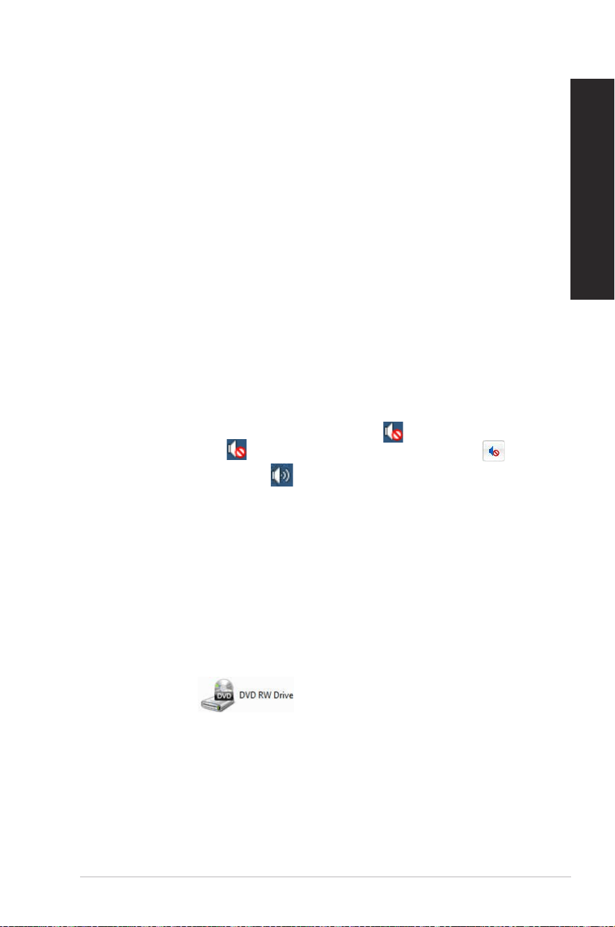
• Ensure that your computer’s system sounds are not Muted.
• If it is muted, the volume icon is displayed as
. To enable the system
sounds, click
from the Windows
®
notication area, then click .
• If it is not muted, click
and drag the slider to adjust the volume.
• Connect your speakers to another computer to test if the speakers arer
working properly.
? The DVD drive cannot read a disc.
• Check if the disc is placed with the label side facing up.
• Check if the disc is centered in the tray, especially for the discs with
non-standard size or shape.
• Check if the disc is scratched or damaged.
? The DVD drive eject button is not responding.
1. From the Start menu, click File Explorer.
2. Right-click
, then click Eject from the menu
54
Chapter 5: Troubleshooting
ENGLISH
Power
Problem Possible Cause Action
No power
(The power
indicator is off)
Incorrect power voltage
• Set your computer’s power voltage
switch to your area’s power
requirements.
• Adjust the voltage settings. Ensure
that the power cord is unplugged
from the power outlet.
Your computer is not
turned on.
Press the power key on the front panel
to ensure that your computer is turned
on.
Your computer’s power
cord is not properly
connected.
• Ensure that the power cord is
properly connected.
• Use other compatible power cord.
PSU (Power supply unit)
problems
Contact the ASUS Service Center
about installing another PSU on your
computer.
Display
Problem Possible Cause Action
No display
output after
turning the
computer on
(Black screen)
The signal cable is
not connected to the
correct VGA port on your
computer.
• Connect the signal cable to the
correct display port (onboard VGA or
discrete VGA port).
• If you are using a discrete VGA
card, connect the signal cable to the
discrete VGA port.
Signal cable problems Try connecting to another monitor.
ASUS Desktop PC
55
ENGLISH
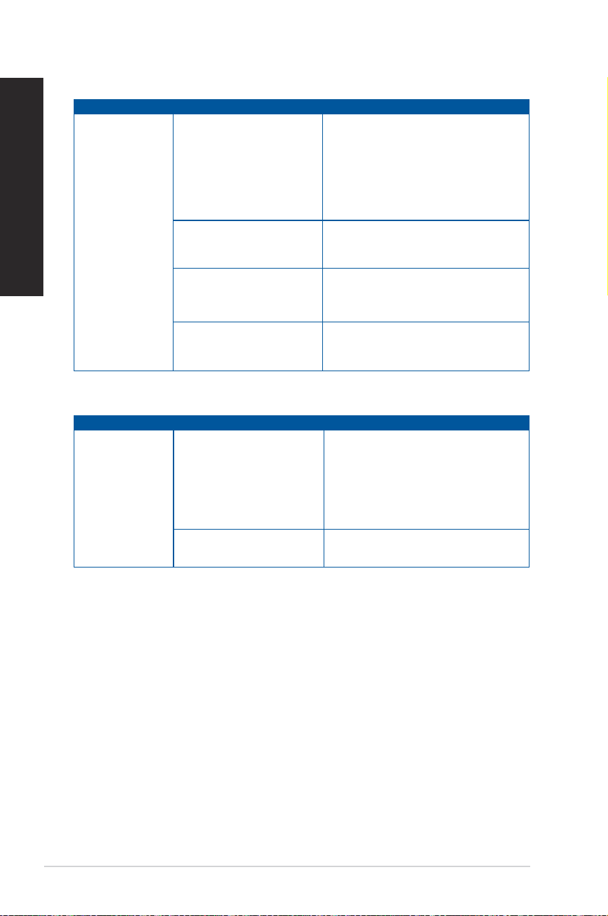
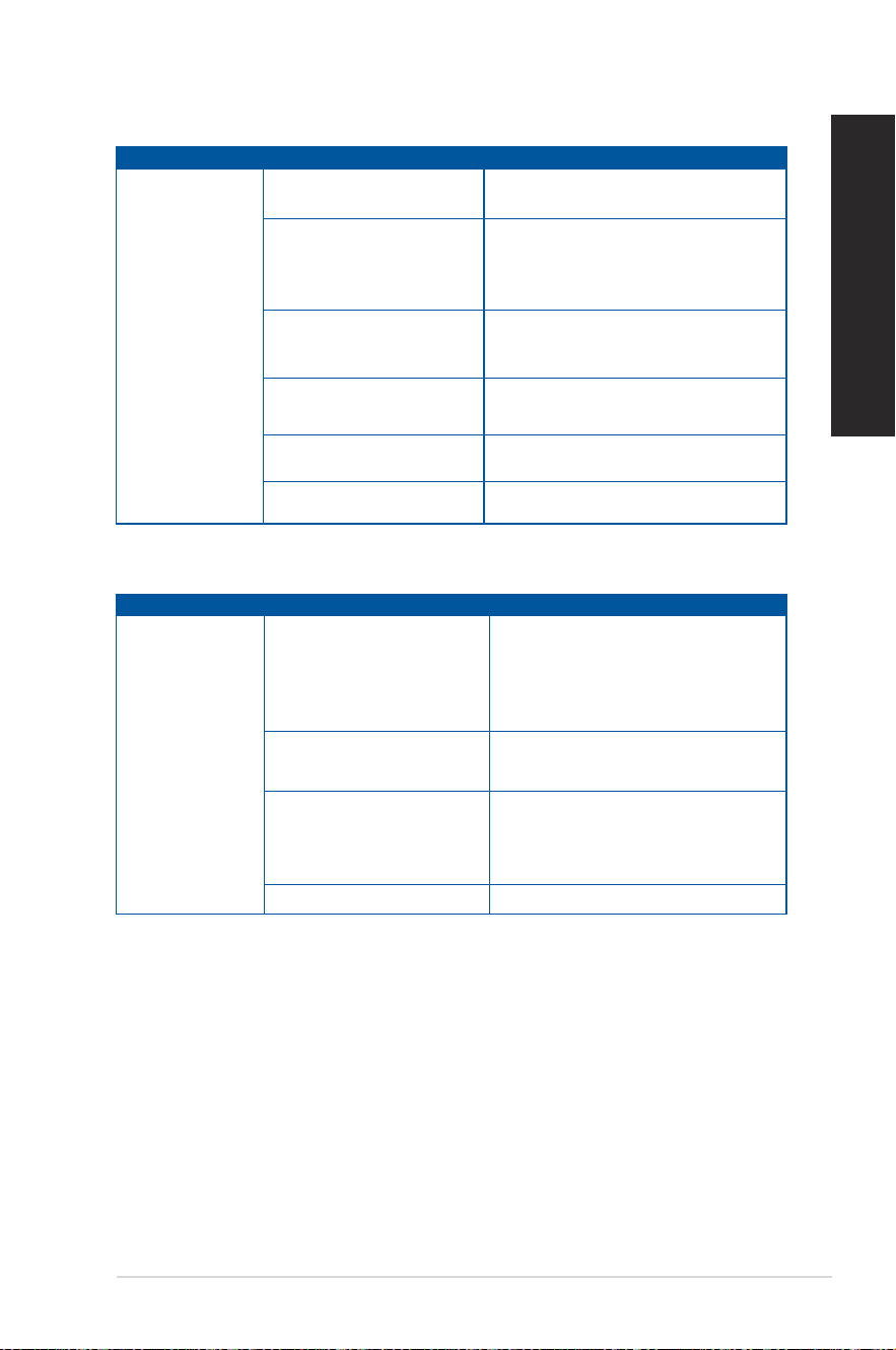
LAN
Problem Possible Cause Action
Cannot access
the Internet
The LAN cable is not
connected.
Connect the LAN cable to your
computer.
LAN cable problems
Ensure the LAN LED is on. If not, try
another LAN cable. If it still does not
work, contact the ASUS service center.
Your computer is not
properly connected to a
router or hub.
Ensure that your computer is properly
connected to a router or hub.
Network settings
Contact your Internet Service Provider
(ISP) for the correct LAN settings.
Problems caused by the
anti-virus software
Close the anti-virus software.
Driver problems Reinstall the LAN driver
Audio
Problem Possible Cause Action
No Audio
Speaker or headphone is
connected to the wrong
port.
• Refer to your computer’s User Guide
for the correct port.
• Disconnect and reconnect the
speaker to your computer.
Speaker or headphone does
not work.
Try using another speaker or
headphone.
The front and back audio
ports do not work.
Try both the front and back audio
ports. If one port failed, check if the
port is set to multi-channel.
Driver problems Reinstall the audio driver
56
Chapter 5: Troubleshooting
ENGLISH
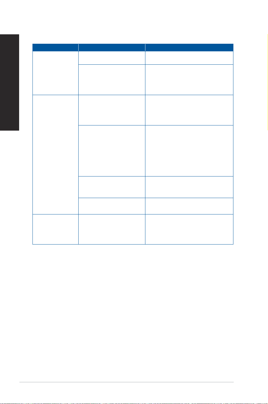
System
Problem Possible Cause Action
System speed is
too slow
Too many programs are
running.
Close some of the programs.
Computer virus attack
• Use an anti-virus software to
scan for viruses and repair your
computer.
• Reinstall the operating system.
The system often
hangs or freezes.
Hard disk drive failure
• Send the damaged hard disk
drive to ASUS Service Center for
servicing.
• Replace with a new hard disk drive.
Memory module problems
• Replace with compatible memory
modules.
• Remove the extra memory modules
that you have installed, then try
again.
• Contact the ASUS Service Center
for assistance.
There is not enough
air ventilation for your
computer.
Move your computer to an area with
better air ow.
Incompatible softwares are
installed.
Reinstall the OS and reinstall
compatible softwares.
The system does
not boot up
An expansion card other
than a graphics card and a
storage device is installed
in PCIEX16_1.
Install this expansion card into
any other PCIe slot and reboot the
system.
ASUS Desktop PC
57
ENGLISH
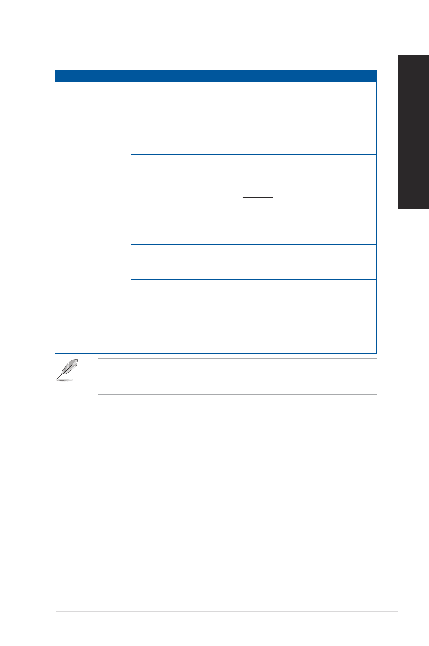
CPU
Problem Possible Cause Action
Too noisy right
after turning on
the computer.
Your computer is booting
up.
It is normal. The fan runs on its
full speed when the computer is
powering on. The fan slows down
after entering the OS.
The BIOS settings have
been changed.
Restore the BIOS to its default
settings.
Old BIOS version
Update the BIOS to the latest
version. Visit the ASUS Support
site at https://www.asus.com/
support/ to download the latest BIOS
versions.
Computer is too
noisy when in use.
The CPU fan has been
replaced.
Ensure that you are using a
compatible or ASUS-recommended
CPU fan.
There is not enough
air ventilation for the
computer.
Ensure that your computer is
working in an area with good air ow.
The system temperature is
too high.
• Update the BIOS.
• If you know how to reinstall the
motherboard, try to clean the inner
space of the chassis.
• Contact the ASUS Service Center
for assistance.
If the problem still persists, refer to your Desktop PC’s warranty card and contact the ASUS
Service Center. Visit the ASUS Support site at https://www.asus.com/support for the
service center information.

58
Chapter 5: Troubleshooting
ENGLISH
MyASUS in WinRE
This desktop model supports MyASUS exclusively in the Windows Recovery Environment
(WinRE) for diagnosing memory, storage, USB devices, and for performing ASUS Recovery.
How to Access WinRE
To enter WinRE, use one of the following methods:
1. Open the Start menu, click the Power button, hold down the Shift key, and select
Restart.
2. Navigate to Settings > Recovery, then select Restart now under Advanced startup.
• Do not manually install MyASUS: This desktop model does not support the diagnostic
tools included in the standard application. Manual installation may also overwrite the
system’s specialized BIOS.
• If a BIOS update is required, please download the appropriate version directly from the
ocial ASUS Support site at https://www.asus.com/support.
ASUS Desktop PC
59
Appendix
Working with Windows
®
Starting for the rst time
When you start your computer for the rst time, a series of screens appear to guide you in
conguring your Windows
®
operating system. Follow the onscreen instructions to congure
the following basic items:
• Personalize
• Get online
• Settings
• Your account
After conguring the basic items, Windows
®
proceeds to install your apps and preferred
settings. Ensure that your computer is kept powered on during the setup process. Once the
setup process is complete, the Desktop appears.
The screenshots in this chapter are for reference only.
Start menu
The Start menu is the main gateway to your computer’s programs, Windows
®
apps, folders,
and settings. You can use the Start menu to do these common activities:
• Start programs or Windows
®
apps
• Open commonly used programs or Windows
®
apps
• Adjust computer settings
• Get help with the Windows
®
operating system
• Turn off your computer
• Log off from Windows
®
or switch to a different user account
Launching the Start menu
You can launch the Start menu in two ways:
• Position your mouse pointer over the Start icon on your desktop then click it.
• Press the Windows
®
logo key on your keyboard.
Appendix Working with Windows
®

60
Appendix: Working with Windows
®
ENGLISH
Opening programs from the Start menu
One of the most common uses of the Start menu is opening programs installed on your
Computer. You can open programs in two ways:
• Position your mouse pointer over the program then click to launch it.
• Use the arrow keys to browse through the programs. Press
to launch it.
Windows
®
apps
Some Windows
®
apps require signing in to your Microsoft account before they are fully
launched.
Launching Windows
®
apps from the Start menu
You can launch Windows
®
apps in two ways:
• Position your mouse pointer over the app then click to launch it.
• Use the arrow keys to browse through the apps. Press
to launch an app.
Connecting to wireless networks
Wi-Fi
Access emails, surf the Internet, and share applications via social networking sites using your
computer’s Wi-Fi connection.
Connecting Wi-Fi
Connect your computer to a Wi-Fi network by using the following steps:
1. Click/Tap the Wi-Fi icon from the taskbar to enable Wi-Fi.
2. Select an access point from the list of available Wi-Fi connections.
3. Select Connect to start the network connection.
You may be prompted to enter a security key to activate the Wi-Fi connection.
Bluetooth
Use Bluetooth to facilitate wireless data transfers with other Bluetooth-enabled devices.
Pairing with other Bluetooth-enabled devices
You need to pair your computer with other Bluetooth-enabled devices to enable data
transfers. Connect your devices by using the following steps:
1. Launch Settings from the Start menu.
2. Select Devices > Bluetooth to search for Bluetooth-enabled devices. (for Windows
®
10)
Select Bluetooth & devices > Add device to search for Bluetooth-enabled devices.
(for Windows
®
11)

ASUS Desktop PC
61
ENGLISH
3. Select a device from the list to pair your computer with the device.
For some Bluetooth-enabled devices, you may be prompted to key in the passcode of your
computer.
Connecting to wired networks
You can also connect to wired networks, such as local area networks and broadband Internet
connection, using your computer’s LAN port.
Contact your Internet Service Provider (ISP) for details or your network administrator for
assistance in setting up your Internet connection.
Turning your computer o
You can turn off your computer by doing either of the following procedures:
• Launch the Start menu, select the power icon then select Shut down to do a normal
shutdown.
From the log-in screen, select the power icon then select Shut down.
• Press
to launch Shut Down Windows. Select Shut down from the drop-
down list then select OK.
If your computer is unresponsive, press and hold the power button for at least four
(4) seconds until your computer turns off.

62
Appendix: Working with Windows
®
ENGLISH
Putting your computer to the O mode / the lowest power
mode
You can put your computer to the Off mode / the lowest power mode in the following way:
Enter Control Panel in the search bar and open it (View by: Category), select Hardware and
Sound > Power Options > Choose what the power button does, click Change settings that
are currently unavailable, uncheck Turn on fast startup (recommended) and click Save
changes.
• Launch the Start menu, select the power icon then select Shut down to do a normal
shutdown.
From the log-in screen, select the power icon then select Shut down.
• Press
to launch Shut Down Windows. Select Shut down from the drop-
down list then select OK.
• If your computer is unresponsive, press and hold the power button for at least four
(4) seconds until your computer turns off.
Putting your computer to sleep
You can put your computer to Sleep mode in two ways:
• Launch the Start menu, select the power icon then select Sleep to put your
computer to sleep.
From the log-in screen, select the power icon then select Sleep.
• Press
to launch Shut Down Windows. Select Sleep from the drop-down
list then select OK.
You can also put your computer to Sleep mode by pressing the power button once.