USER MANUAL
COOKER HOOD
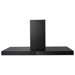
eiQ60PBSLIMEN
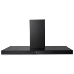
eiQ90PBSLIMEN
Thank you for choosing electriQ
Please read this user manual before using this
product and keep it safe for future reference.
Visit our page www.electriQ.co.uk for our entire product range

2
CONTENTS
SAFETY
3
PRODUCT OVERVIEW
5
PARTS LIST
6
INSTALLATION
7
V-FLAP INSTALLATION
7
OPTIONS FOR VENTILATION
8
INSTALLING THE UNIT
9
OPERATION
10
FILTER INFORMATION
11
BULB REPLACEMENT
12
CLEANING AND MAINTENANCE
12
TROUBLESHOOTING
13
SUPPORT
14
PRODUCT FICHE
15

3
SAFETY PRECAUTIONS
Whilst this product is compliant with all safety requirements, incorrect or inappropriate
use can lead to both personal injury and potential damage to property. Please read
the contents of this instruction booklet thoroughly before fitting or using this appliance.
• The cooker hood must be installed in accordance with the installation instructions
and all measurements followed.
• All installation work must be carried out by a competent person or qualified
electrician.
• The unit must be connected to an earthed power supply.
• If venting externally, make sure the ducting has no bends sharper than 90 degrees
as this will reduce the efficiency of the cooker hood.
• The cooker hood is for domestic use only and is not designed for commercial use. It
should only be used for the purpose it was intended – to extract vapours and
cooking odours.
• Do not flambé or use an open flame under the cooker hood.
• Do not try to use the cooker hood without the grease filters or if the filters are
excessively greasy. They should be cleaned regularly (see “Maintenance”) or
replaced as necessary.
• The extraction fan must be level to avoid grease collection at one end, as this could
cause a potential fire risk.
• Do not leave frying pans unattended during use because overheated fat or oils
might catch fire.
• If the cooker hood is damaged, do not attempt to use it.
• If the supply cord is damaged, it must be replaced by the manufacturer, its service
agent or a similarly qualified person in order to avoid a hazard.
• This appliance can be used by children aged from 8 years and above and persons
with reduced physical, sensory or mental capabilities or lack of experience and
knowledge if they have been given supervision or instruction concerning use of the
appliance in a safe way and understand the hazards involved.
• Children shall not play with the appliance. Cleaning and user maintenance shall not
be made by children without supervision.
• Children should be supervised to ensure that they do not play with the appliance. It
is not a toy.
• The plug must be accessible after installation for isolation in case of an emergency
– or an appropriate fused switch if the unit is hard-wired to the mains via a spur.
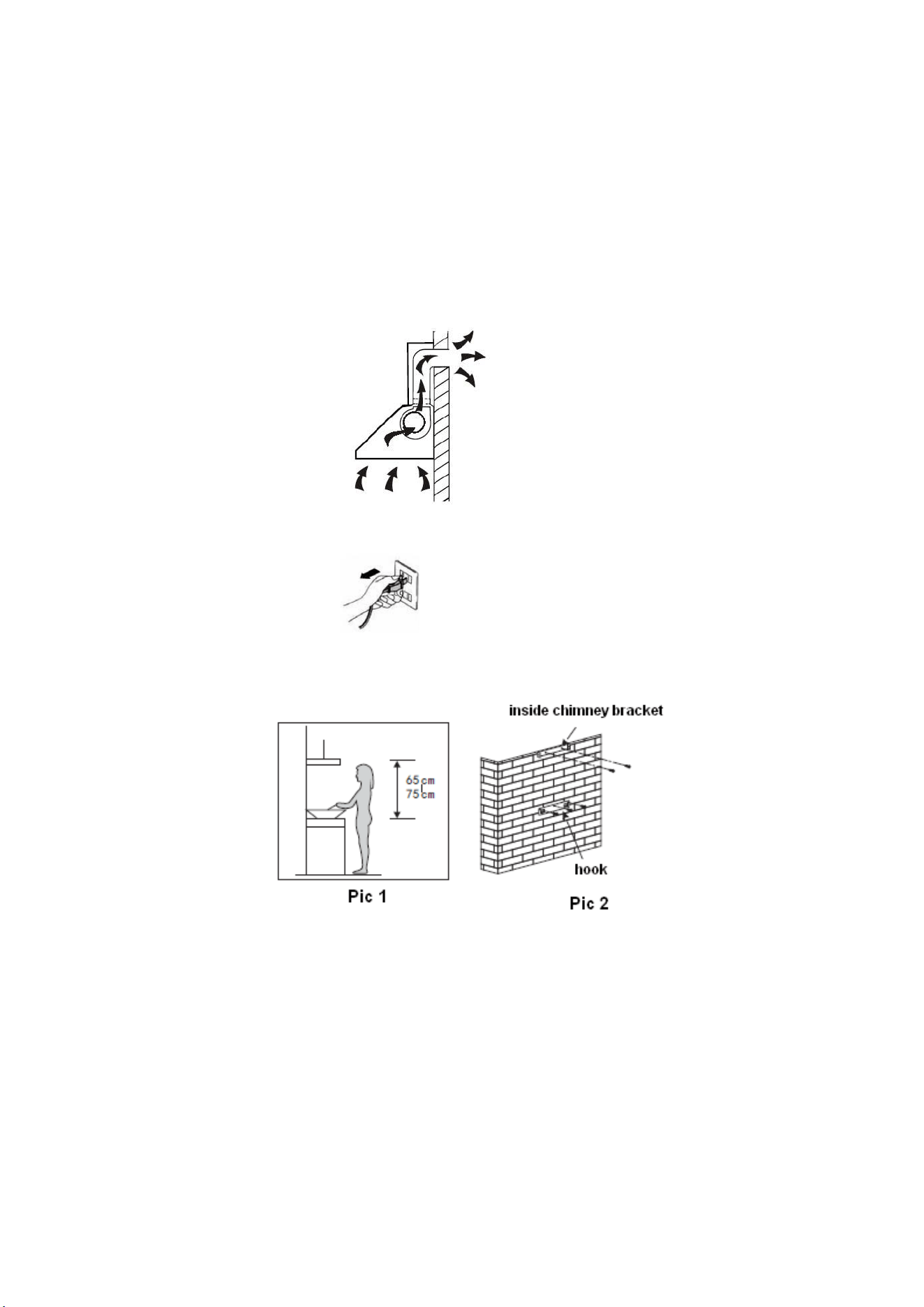
• The minimum distance between the surface of the hob and the lowest part of the
hood should be at least 65cm. A distance of between 65cm and 75cm gives peak
efficiency.
• The air must not be discharged into a flue that is used for exhausting fumes from
appliances burning gas or other fuels.
• When the hood is vented externally and used with appliances which burn fuel (e.g.
gas, oil, wood) the area must be sufficiently ventilated to ensure safe operation.
Fresh air must be allowed to freely enter the room to prevent a partial vacuum.

4
• A partial vacuum can starve the heating appliance of oxygen, impairing combustion.
It can also prevent toxic fumes from leaving the room, or can cause fumes to be
sucked into the room from outside.
• Safe operation is only possible when the partial vacuum within the working area
does not exceed 4 Pa (0.04 mbar). This can be achieved by ensuring air is able to
enter the room from outside through a suitable sized opening which cannot be
sealed during operation. A number of alternative solutions are available to ensure
this. If in any doubt, professional advice should be sought.
• Regulations concerning the discharge of air have to be fulfilled.
• There is a potential fire risk if cleaning is not carried out in accordance with the
instructions.
• Clean your appliance periodically by following the method given in the chapter
MAINTENANCE
• If used in recirculation mode, the charcoal filters trap odours and must be replaced
at least once a year depending on how frequently the cooker hood has been used.
• For safety reasons, please use only the same size of fixing or mounting screw,
which are recommended in this instruction manual.
• Warning: Failure to install the screws or fixing device in accordance with these
instructions may result in electrical hazards
CAUTION: Accessible parts of the hood can become very hot during
use with cooking appliances, whether in use or not, due to heat rising from
the hob. Sufficient time should be allowed for the unit to cool before touching
either the housing or the grease filters
5
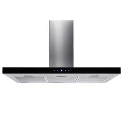
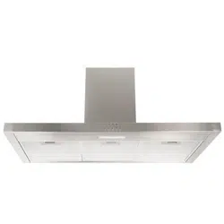
PRODUCT OVERVIEW
6
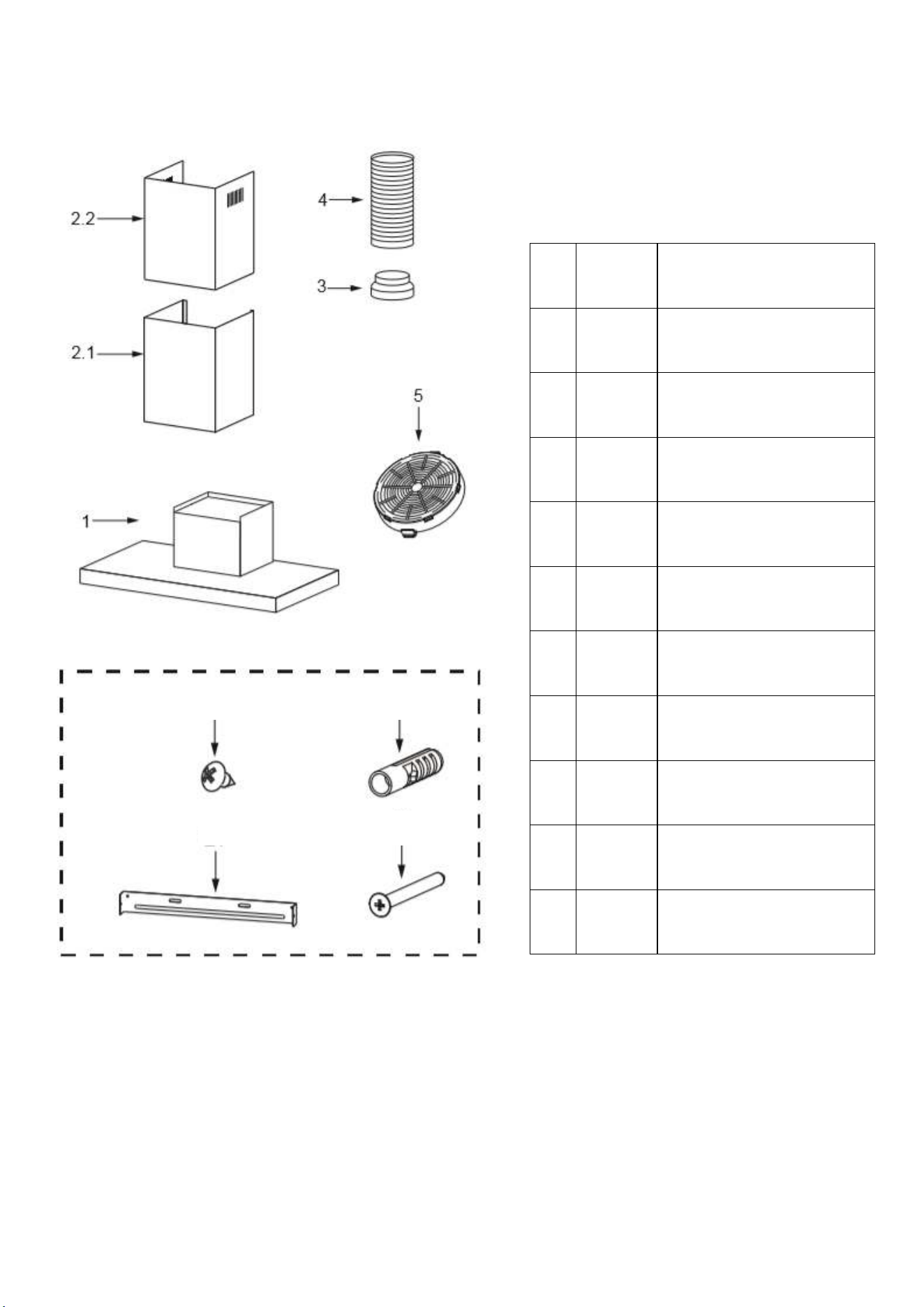
PARTS LIST
Ref.
Quantity
Description
1
1
Hood Body
2.1
1
Lower decorative chimney
2.2
1
Upper decorative chimney
3
1
V-flap
4
1
Exhaust pipe (Not included)
5
1
Charcoal filter
6
6
Screws 4,2 x 9,5 / Screws 4x8
7
7
Wall Plugs
8
2
Chimney fixing bracket
9
7
Screws 5 x 50
6 7
8 9
7
INSTALLATION (VENT OUTSIDE)
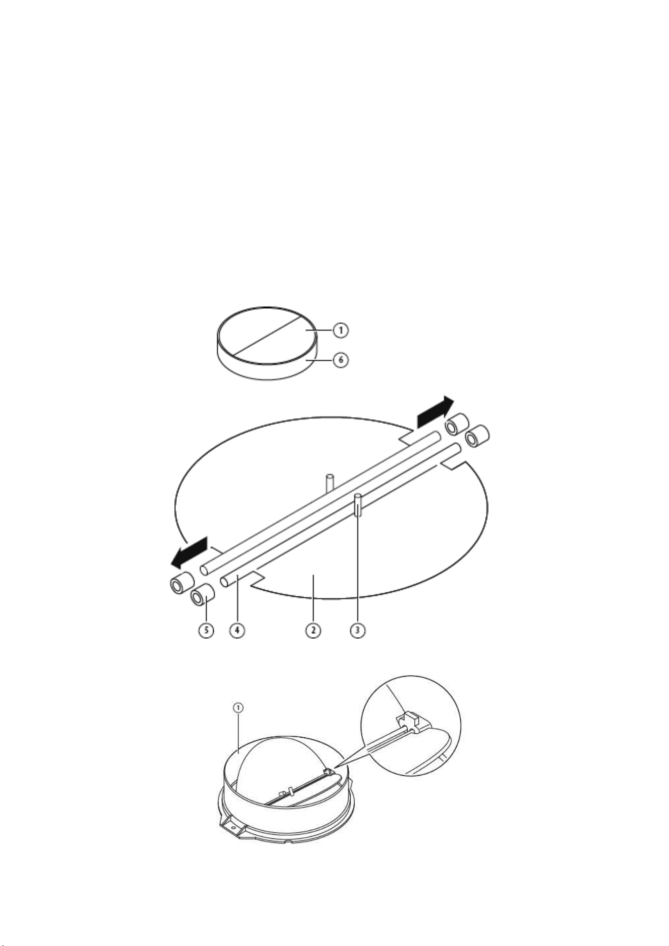
MOUNTING OF THE V-FLAP
If the cooker hood does not have an assembled V-flap 1, you should mount the half-parts to its body.
The images only show an example of how to mount the V-flap, the outlet may be various according to
different models and configuration.
To mount the V-flap 1 you should:
1. Mount two half-parts “2” into the body “6”
2. A pin 3 should be top oriented
3. The axis “4” should be inserted in the holes “5” on body
4. Repeat all the operations for the 2nd half-part
OPTIONS FOR VENTILATION
This hood can be set up for either external venting or recirculation of the air. The type of setup should
be decided before commencing installation.
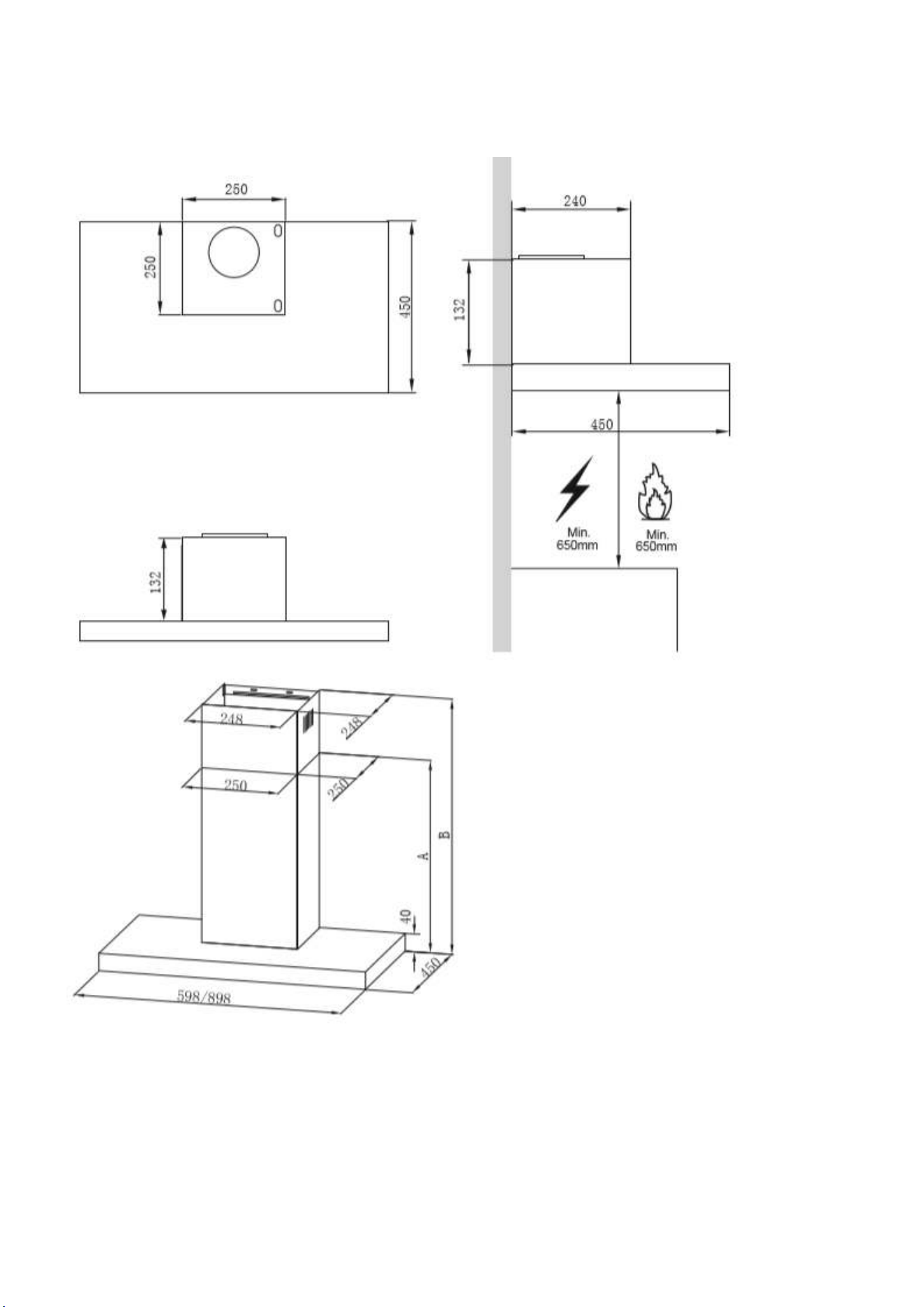
INSTALLATION
If you have an outlet to the outside, your cooker hood can be connected as below picture by means of
an extraction duct (enamel, aluminum, flexible pipe or non-flammable material with an interior diameter
of 150mm)
1. Before installation, turn the unit off and unplug it from the outlet.
2. The cooker hood should be placed at a distance of 65~75cm above the cooking plane for best
effect.
3. Install the hook on a suitable place once the installation height is fixed, and keep it in line. The fixed
position of the inside chimney bracket is the highest place of chimney. See pic 2.
9
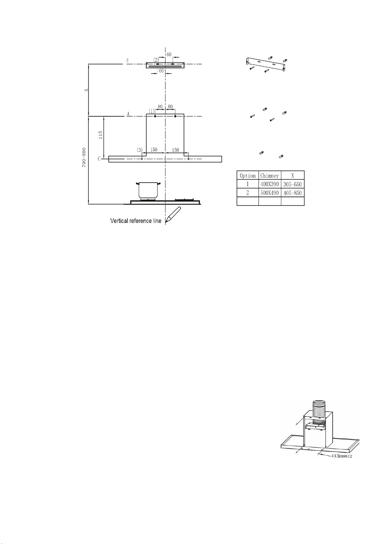
INSTALLATION
•
Draw a vertical line up to the ceiling or up to the upper limit, at the centre of the area in
which the hood is to be fitted.
•
A horizontal line A at 790– 890 mm above the cooker top.
•
A horizontal line B at a X mm above the horizontal line A.
• A horizontal line C at a 115mm below the horizontal line A.
• Mark a point (1) on the horizontal line A, 80 mm to the vertical reference line.
•
Repeat this operation on the other side, checking that the two marks are levelled.
•
Mark a point (2) on the horizontal line B, 60 mm to the vertical reference line.
•
Repeat this operation on the other side, checking that the two marks are on the same
horizontal line.
•
Mark a point (3) on the horizontal line C, 150 mm to the vertical reference line. Repeat this
operation on the other side, checking that the two marks are levelled.
FIX THE BRACKETS
• Drill holes at the marked points with a ɸ10 mm drill bit.
•
Insert the Wall Plugs 11 into the holes.
•
Fix a Chimney fixing bracket 21 with 2 screws 10 (5 x 50) at the
horizontal line B.
Screw 2 screws 10 (5 x 50) to Wall Plugs 11 at the
horizontal line A; approximately the four fifth length of the screws 10
(5 x 50) was screwed into the Wall Plugs 11, used for hook the
hood.
LOWER DECORATIVE CHIMNEY
• Fix the exhaust pipe on the hood body, connect chimney and hood body with 2 screws 12.
connect chimney fixing bracket and chimney with 2 screws 12.
HOOK THE HOOD BODY
⚫
Hook the hood body to the 2 screws 10 (5 x 50) at the horizontal line A.
⚫ Level the hood body itself.
⚫ Remove the filter from the inside of the hood body, fix the screws 10 to Wall Plugs 11 at the points
(3).
HINTS FOR EXHAUST DUCT INSTALLATION
The following rules must be strictly followed to obtain optimal air extraction:
• Keep expansion pipe short and straight.
• Do not reduce the size or restrict expansion pipe.
• When using expansion pipe always install the pipe pulled taut to minimize pressure loss.
• Failure to observe these basic instructions will reduce the performance and increase noise levels of
the cooker hood.
• Any installation work must be carried out by a qualified electrician or competent person.
•Do not connect the ducting system of the hood to any existing ventilation system which is being used
for any other appliance, such as warmer tube, gas tube, hot wind tube.
•The angle of the bend of the expansion pipe should not be less than 120º; you must direct the pipe
horizontally, or, alternatively, the pipe should go up from the initial point and should be led to an outer
wall.
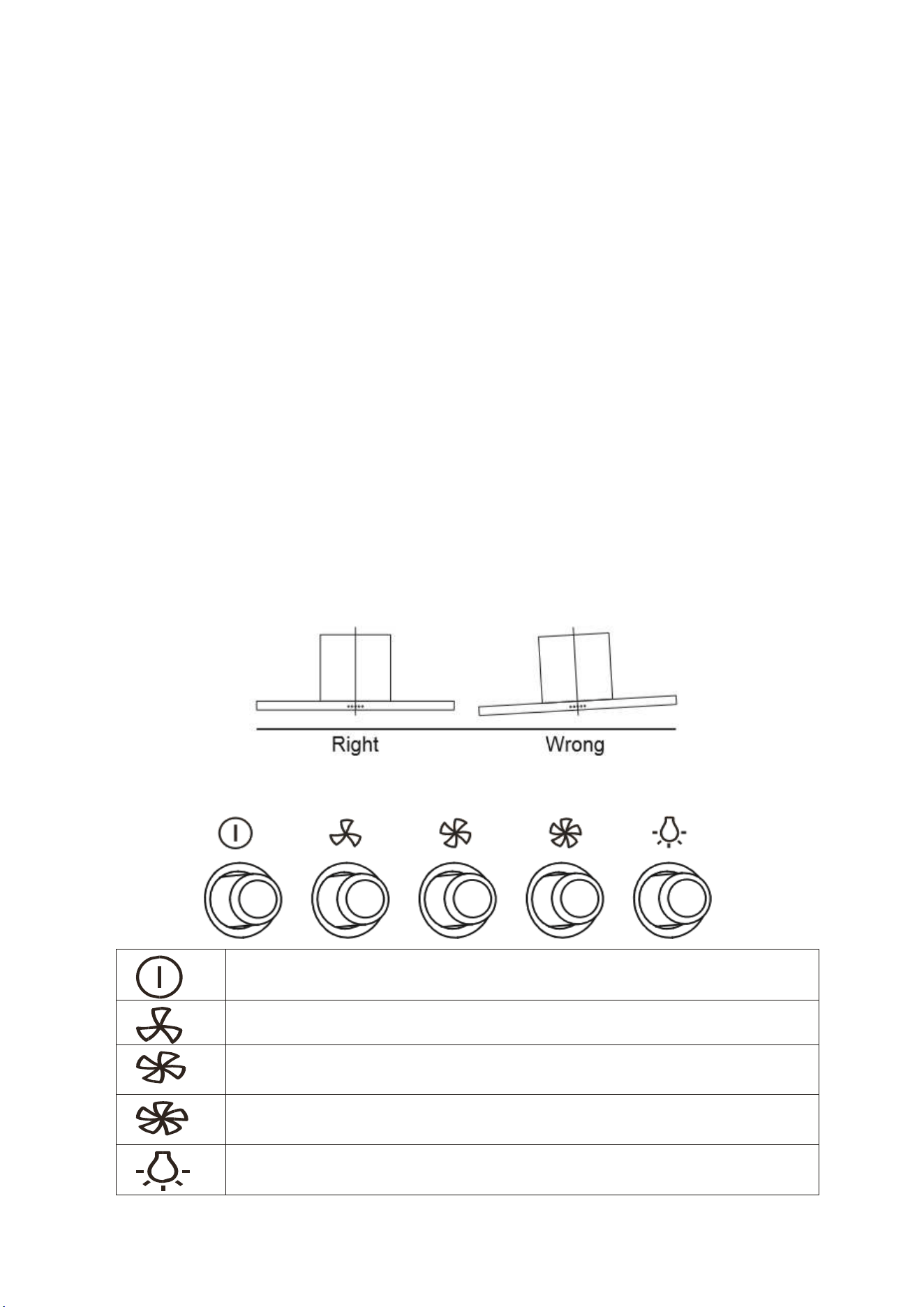
•After the installation, make sure that the cooker hood is level to avoid grease collection at on end.
•Ensure the expansion pipe selected for installation complies with relevant standards and is fire
retardant.
OPERATION
OFF MOTOR SWITCH: Press on this switch to stop the motor
operation.
SPEED SWITCH: Press on this switch, the motor runs at LOW speed.
SPEED SWITCH: Press on this switch, the motor runs at MEDIUM
speed.
SPEED SWITCH: Press on this switch, the motor runs at HIGH
speed.
ON/OFF LIGHTING SWITCH: Press on this switch to turn on the
lights, and press again to turn them off.
11
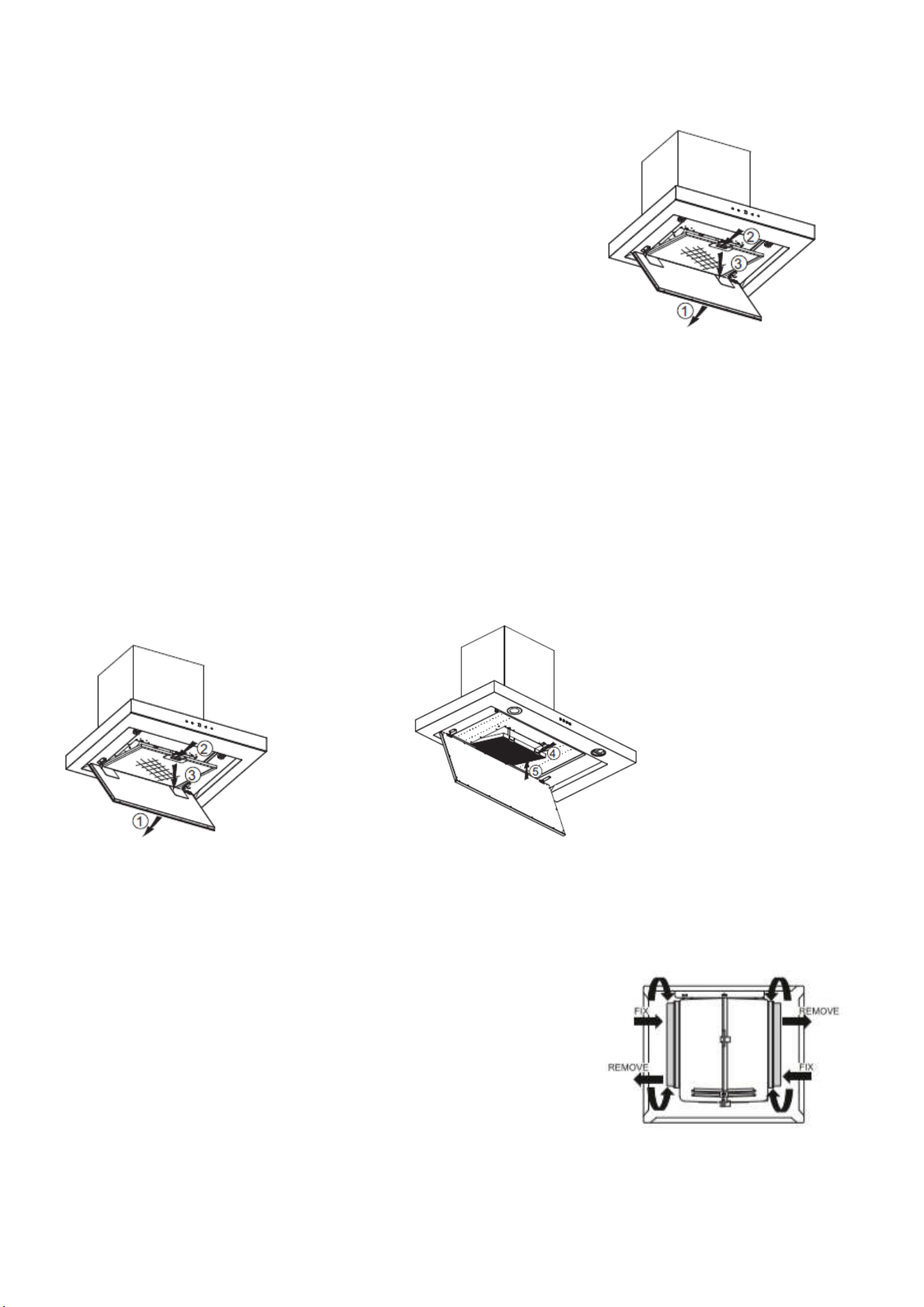
INSTALLING GREASE MESH FILTERS
• To install filters for the following four steps.
• Angle the filter into slots at the back of the hood.
• Push the button on handle of the filter.
• Release the handle once the filter fits into a resting position.
• Repeat to install all filters.
Replacements are available from the retailer the hood was
purchased from under reference:
60cm version takes grease filter eiQM60CGFILTER x 2
90cm version takes grease filter eiQMCHIMFILTER90 x 3
CARBON FILTER-not supplied
Activated carbon filter can be used to trap odors. Normally the activated carbon filter should be
changed at three or six months according to your cooking habit. The installation procedure of activated
carbon filter is as below.
Replacements are available from the retailer the hood was purchased from under reference:
eiqmidcar90chim
(1) The aluminum filter should be detached first. Press the lock and pull it downward.
(2) The dismantle method of carbon filter can refer to below pictures.
(3) Take out the carbon filter and change it with a new one.
(4) Apply reverse procedure to install the charcoal filter.
(5) Put the aluminium filter back.
NOTE:
• Make sure the filter is securely locked. Otherwise, it would loosen and cause dangerous.
• When activated carbon filter attached, the suction power will be lowered.
CHARCOAL FILTER
Remove the metal grease filters. Remove the saturated activated
charcoal filter. Fit the new filters. Replace the metal grease filters.
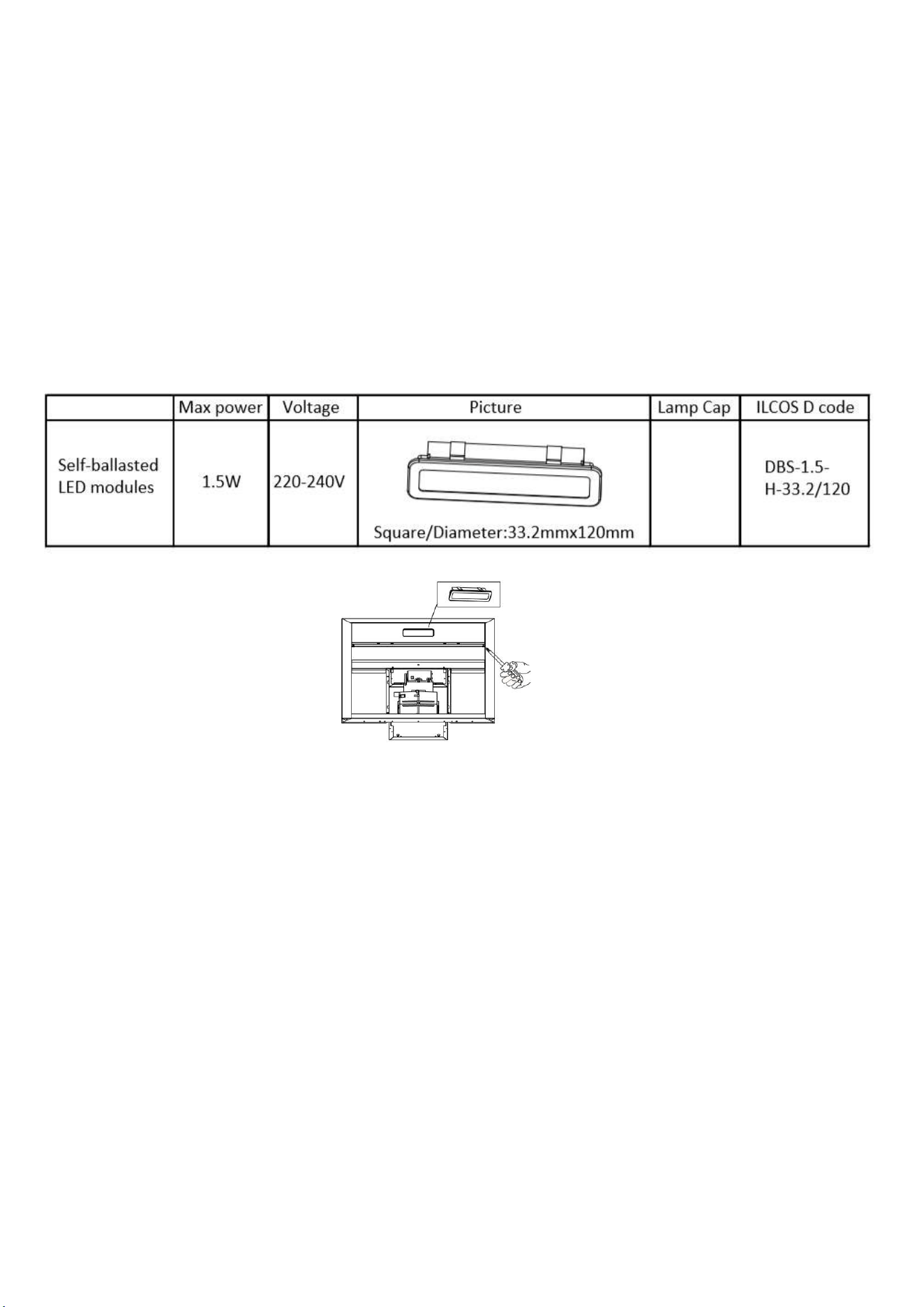
BULB REPLACEMENT
Before changing the bulb, ensure the hood is turned off and the power is disconnected before
attempting to change the bulb. Wait until the flitting has cooled down before commencing
replacement.
• Open the LED light plate assembly and take away the grease filter. See pic 1.
• Find the light wire at the back of the wire outlet. Then slightly pull the light connecting wire out, and
dismantle the terminal of the light connecting wire. See pic 2.
• Remove 4pcs screws on the hinge of light plate assembly, take out the light plate assembly and pull
out the light wire. If the light wire cannot be pulled out, it can be cut directly with scissors.
• Apply the reverse procedure to install the light back.
MAINTENANCE
Before cleaning, switch the unit off and pull out the plug, or switch off at the relevant mains switch if
the unit has been hard-wired in. Make sure the unit has no power being fed to it.
REGULAR CLEANING
Use a soft cloth moistened with warm mildly soapy water or household cleaning detergent. Never use
metal pads, chemicals, abrasive material or a stiff brush to clean the unit.
NOTE: Do not use a steam-cleaner to clean the hood; electrical components could be damaged or
short-circuit as a result.
13
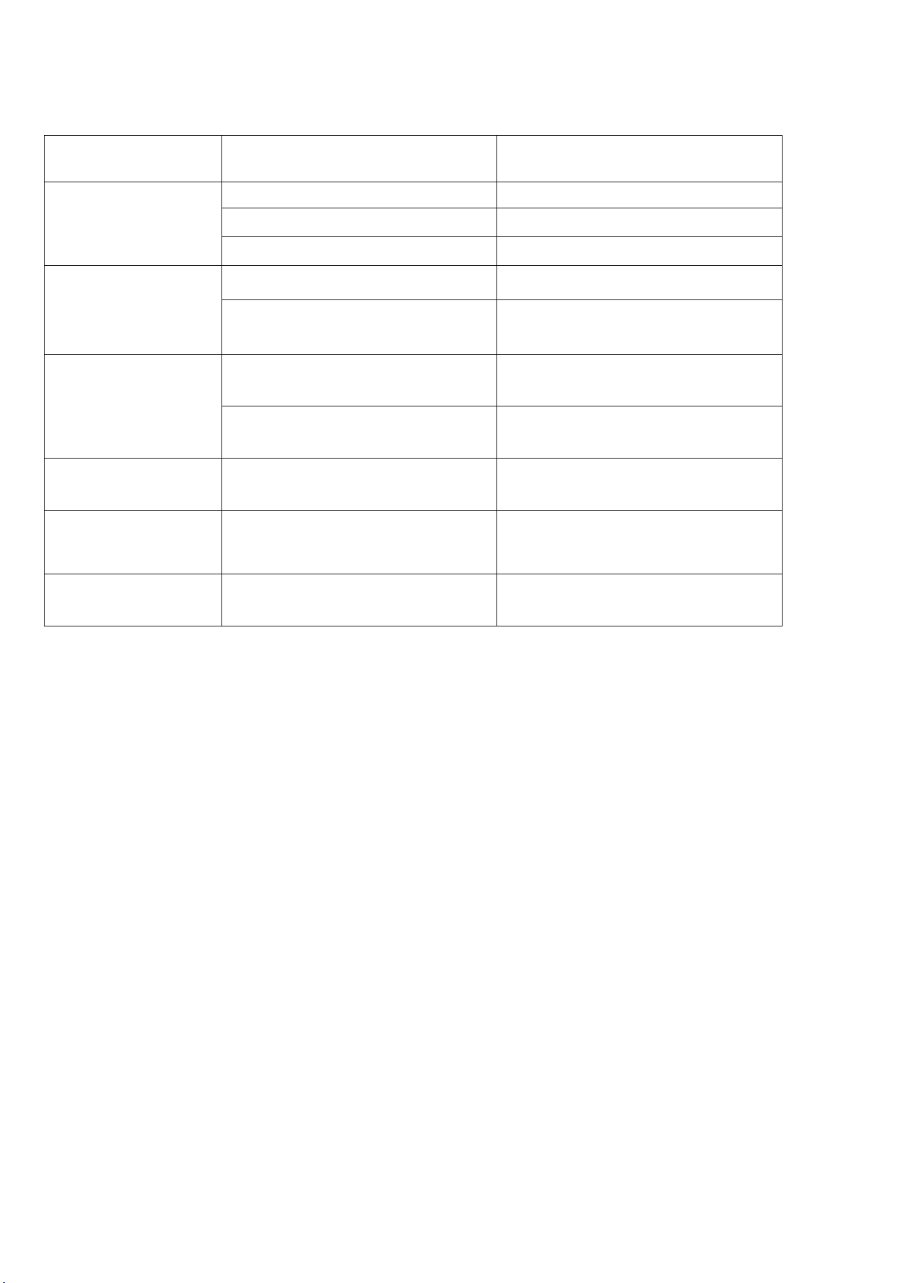
TROUBLESHOOTING
NOTE:
Any electrical repairs to this appliance must conform to your local, state and federal laws. Please
contact the service center if in any doubt before undertaking any of the above. Always disconnect the
unit from the power source when opening the unit.
Fault
Possible Cause
Solution
Light on, but motor
does not work
Fan switch turned off
Select a fan switch position.
Fan switch failed
Contact service center.
Motor failed
Contact service center.
Light does not
work, motor does
not work
House fuses blown
Reset/Replace fuses.
Power cord loose or
disconnected
Refit cord to power outlet.
Switch power outlet on.
Oil leakage
One way valve and the outlet
are not tightly sealed
Take down the one way valve
and seal with sealant.
Leakage from the connection of
chimney and cover
Take chimney down and seal.
Lights not working
Broken/Faulty globes
Replace globes as per this
instruction.
Insufficient suction
The distance between the
cooker hood and the gas top is
too far
Refit the cooker hood to the
correct distance.
The Cooker hood
inclines
The fixing screw not tight
enough
Tighten the hanging screw and
make it horizontal.
INFORMATION FOR DISMANTLING
Do not dismantle the appliance in a way which is not shown in the user manual. The appliance could
not be dismantled by user. At the end of life, the appliance should not be disposed of with household
waste. Check with your Local Authority or retailer for recycling advice.
electriQ UK SUPPORT
www.electriQ.co.uk/support
Call: 0871 984 4416
Office hours: 9AM - 5PM Monday to Friday
www.electriQ.co.uk
Unit J6, Lowfields Business Park
Lowfields Way, Elland
West Yorkshire, HX5 9DA
Recycling facilities are now available for all customers at which you can
deposit your old electrical products. Customers will be able to take any old
electrical equipment to participating sites run by their local councils. Please
remember that this equipment will be further handled during the recycling
process, so please be considerate when depositing your equipment. Please
contact the local council for details of your local household waste recycling centers.
15
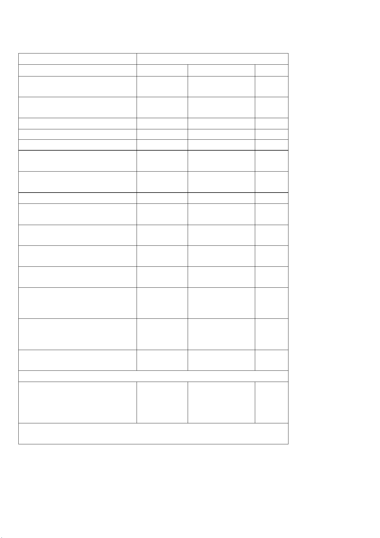
PRODUCT FICHE
Model Identification
eiQ60PBSLIMEN eiQ90PBSLIMEN
Symbol
Value
Unit
Annual Energy
Consumption
AEChood
25.6
kWh/A
Standard Annual Energy
Consumption
SAEChood
42.5
kWh/a
Time increase factor
F
1.5
Fluid Dynamic Efficiency
FDEhood
15.9
Energy Efficiency Index
EEIhood
60.2
Measured air flow rate at
best efficiency point
QBEP
191.4
m3/h
Measured air pressure at
best efficiency point
PBEP
144
Pa
Maximum air flow
Qmax
342.0
m3/h
Measured electric power
input at best efficiency point
WBEP
49.5
W
Nominal power of the
lighting system
WL
1.5*1
W
Measured power of the
lighting system
WL
1.4
W
Measured value of the
Lighting Efficiency
LEhood
35
Lux/W
Average illumination of the
lighting system on the
cooking surface
Emiddle
49
lux
Measured power
consumption in standby
mode
Ps
N/A
W
Measured power
consumption off mode
Po
0
W
Tested according to EN 50564:2011
Sound power level
LWA
Minimum
speed: 52
Maximum
speed: 65
dB
Tested according to EN 60704-2-13:2011, EN 60704-1:2010 +
A11:2012