DIGITAL MULTIMETER
USER’S MANUAL
1.1 Security Information…………………………………1
1.1.1 Security Instructions…………………………………1
1.1.2 Security Precautions………………………………1-3
1.1.3 Security Symbol………………………………………3
1.1.4 Safe maintenance habits…………………………3-4
1.2 Input protection measures…………………………4
2.1 Appearance of the instrument ……………………5
2.2 Description of display symbol ……………………6-7
2.3 Description of function button……………………7
2.4 Description of Input socket………………………7
2.5 Accessories……… ……… ……… ……… ……… …8
3.1 Normal operatio n…… ……… ……………………8
3.1.1 Reading Hold Mode…………………………………8
3.1.2 Lighting function……………………………………8
3.1.3 Frequency conversion voltage measurement function…8
3.1.4 Automatic shutdown function.……………………8
3.2 Measurement Guide………………………………8
3.2.1 Measuring AC and DC voltages………………9-10
3.2.2 Measuring resistance…………………………10-11
3.2.3 Test of the Diodes…………………………………11
3.2.4 Buzzer and continuity test……………………11-12
3.2.5 Measuring capacitance……………………………12
3.2.6 Measurement frequency……………………… 12-13
3.2.7 Measuring current ……………………………13-14
3.2.8 NCV test……………………………………………14
3.2.9 Live Line and Netural Line Distinguish…………14
3.2.10 Temperature measurement………………………15
Table of Contents
4.1 Comprehensive indicators …………………………15-16
4.2 Precision Index …………………………………………16
4.2.1 DC voltage…………………………………………16
4.2.2 AC voltage…………………………………………16
4.2.3 Frequency…………………………………………17
4.2.4 Resistance…………………………………………17
4.2.5 Diode…………………………………………………17
4.2.6 Buzzer and continuity test…………………………18
4.2.7 Capacitance …………………………………………18
4.2.8 Direct current………………………………………19
4.2.9 Alternating current…………………………………19
4.2.10Temperature…………………………………………20
5.1 General Maintenance ………………………………20
5.2 Replacing the battery………………………………21
1. Overview
2.Instrument indication instructions
3. Operation manual
5. Instrument maintenance
4. Technical indicators
1. Overview
1 2 3 4
6
7
8 9 11 12
Symbol Description
Battery undervoltage indicator / low battery capacity
In order to avoid suffering electric shock or personal
injury caused by incorrect readings, the battery should
be replaced as soon as possible when the low voltage
symbol display of the battery appears.
Indicator for automatic close-down function
High voltage warning symbol
Negative input polarity indication
AC input indication.
DC input indication.
The instrument is in continuity test mode.
The instrument is in diode test mode.
The instrument is in data hold mode.
Temperature unit (°C: Celsius; °F: Fahrenheit)
Duty cycle
The instrument is in non-contact AC voltage
Frequency conversion y voltage measurement
Firing line test
Manual range
Fuse tube is blown out.
Fuse tube is blown out.
Measurement probe is inserted in wrong
AC
DC
NCV
H
℃/℉
%
V.F.C
Live
Manual
FUSE
LEAd
V:Volts, the unit of voltage.
mV:M illivolts, 1x10⁻³ or 0.001 volts.
V,mV
A:Ampere, the unit of current.
mA: 1x10⁻³ or 0.001 amps.
μA:M icroampere, 1x10⁻⁶ or 0.000001 amps.
A,mA,μA
Ω:Ohm, the unit of resistance.
kΩ:Kilo-ohm, 1000 ohms.
MΩ:Megohm, 1,000,000 ohms.
Ω,kΩ, MΩ
HZ:Hertz, frequency unit.
KHZ:Kilohertz, 1x10³ Hz.
MHz:Megahertz, 1x10⁶ or 1000 kHz.
MKHz
F:Farah, the unit of capacitance.
mF:Millifarad, 1x10⁻³ or 0.001 Farah
μF:Microfarad; 1x10⁻⁶ or 0.000001 Farah.
nF:Nanofarad, 1x10⁻⁹ or 0.000000001 Farah.
mF,μF, nF
2.2 Symbol description of display
2.3 Function button description
2.4 Input socket description
Key
Function description
Input socket
Description
SEL
HOLD
V.F.C
COM
The common input terminal of all measurements is
connected to the common output plug of a black
measurement probe or dedicated multi-function test socket.
Ω
V ℃/℉
Live
Hz %
μA mA
10A
① Operation instruction One
② Measurement probes One Pair
③ 1.5V AA battery One Pair
H
3.2.1 Measuring AC and DC voltages
The DC voltage range of this instrument is: 999.9mV,
9.999V;99.99V and 999.9V,the AC voltage range is: 999.9mV,
9.999V, 99.99V and 750V.
Measurement of AC or DC voltage:
③ The AC voltage value measured using this instrument is the true
RMS (root mean square). For sine waves and other waveforms
(no DC offset), such as square waves, triangle waves, and
staircase waveforms, these measurements are accurate.
V
V
3.2.2 Measuring resistance
To avoid damage to the instrument or the device under test,
turn off all power to the circuit under test and fully discharge
all high-voltage capacitors before measuring resistance.
The instrument's capacitance range is 9.999nF, 99.99nF,
999.9nF, 9.999μF, 99.99μF and 999.9μF,9.999mF.
13
14
16 17 18
Measuring range
999.9mV
9.999V
99. 99V
999.9V
0.1mV
1mV
10mV
100mV
±(0.5% reading +3 digits)
999.9mV
9.999V
99. 99V
750. 0V
0.1mV
1mV
10mV
100mV
±(0.8% reading +3 digits)
±(1% reading + 5 digits)
Input impedance: 10MΩ
Maximum input voltage: 1000Vdc or 750V ac rms.
Frequency response: 40Hz-1KHz true RMS (VFC: 2KHz
attenuation -3dB)
999.9Ω
9.999kΩ
99. 99kΩ
0.1Ω
1Ω
10Ω
100Ω
999. 9kΩ
9.999MΩ
99. 99MΩ
1kΩ
10kΩ
Measuring rangeFunction
0.15V-3V 0.001V
Overload protection: 600V DC/AC
10 0Ω
1Ω
Overload protection: 600V DC/AC
Open-circuit voltage: 1 V
Overload protection: 600V DC/AC
19
20
21
99.99μA
999.9mA
600mA
10A
0.01μA
0.01mA
0.1mA
10mA
±(0.8% reading +3 digits)
Overload protection: mA range fuse tube (FF630mA/250V);
10A range fuse tube (FF10A/250V).
99.99mA
600mA
10A
0.01mA
0.1mA
10mA
Overload protection: 600VDC/AC
To avoid electric shock or personal injury caused by
incorrect readings, replace the battery immediately when
the“ ”symbol appears on the display of the instrument.
Only use the specified fuse (600mA/250V, 10A/250V
fast-thawing fuse)
To avoid electric shock or personal injury, turn off and
check that the measurement probe has been disconnected
from the measurement circuit before opening the battery
cover and replacing it with a new one.
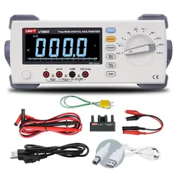
USER’S MANUAL
Table of Contents
This instrument is a 9999-counter, hand-held digital multimeter
with true virtual value and manual/automatic integration. It has a
large, double, invert digital LCD display with simulation bars and
illumination lights which are easy for users to read. It has the
functions of alarm for fuse tube fused, wrong insertion of
measurement probe, overload protection and battery undervoltage
indication. It is an ideal multi-function instrument for either
professionals, factories, schools, enthusiasts or families.
* When using this instrument, the user must observe all
standard safety procedures for the following two aspects:
A Safety procedure for preventing electric shock.
B Safety procedures for the prevention of incorrect use of the
instrument.
It is designed and manufactured according to the safety
requirement for electronic measuring instruments and handheld
digital multimeters specified in the international electrical safety
standard IEC-61010. It meets the requirements of IEC61010's
600V CAT IV, 1000V CAT. III and Pollution Degree 2. Before using
the instrument, please read the instruction manual carefully and
pay attention to the safe working practices.
1.1 Safety Information
1.1.1 Safety Instructions
* To ensure your personal safety, please use the measurement
probe provided with the instrument. Check and make sure
they are intact before use.
1.1.2 Safety Precautions
* When using the instrument near a device with large
electromagnetic interference, the reading of the instrument
will be unstable. A large error may occur.
* Do not use the instrument or the measurement probe when
its appearance is damaged.
* If the instrument is not used correctly, the safety functions
provided by the instrument may expire.
* You must be extremely careful when working around bare
conductors or buses.
* Do not use the instrument near explosive gas, steam or dust.
* Measurements must be taken using the correct input
terminal, functions, and ranges.
* The input value must not exceed the input limit specified for
each range to prevent damage to the instrument.
* When the instrument is connected to the line to be tested,
do not touch the input terminal that is not used.
* When the measured voltage exceeds 60Vdc or 30Vac RMS,
operate carefully to prevent electric shock.
* When measuring with a measurement probe, place your
finger behind the guard ring of the measurement probe.
* Before converting the range, you must ensure that the
measurement probe has left the circuit under test.
* For all DC functions, to avoid the risk of electric shock due
to possible incorrect readings, use the AC function first to
confirm the presence of any AC voltage. Then, choose a
DC voltage range equal to or greater than the AC voltage.
* Before performing resistance, diode, capacitance
measurement or make-and-break test, the power of the
circuit under test must be cut off and all high voltage
capacitors in the circuit under test must be discharged.
* Do not measure resistance or perform make-and-break
tests on live circuits.
* Check the fuse tube of the instrument before making current
measurements. Before connecting the instrument to the
circuit under test, turn off the power of the circuit under test.
* When performing TV service or measuring the power-switching
circuit, you must be careful of the high voltage pulse in the circuit
under test to avoid damage to the instrument.
* This meter is powered by 2 sets of 1.5V AA batteries, which
must be correctly installed in the battery compartment of the
instrument.
* When the battery undervoltage symbol appears, replace
the battery immediately. Insufficient battery power can cause
incorrect instrument readings that can result in electric shock
or personal injuries.
* Do not exceed 1000V when making measurement category III
voltage measurement; do not exceed 600V when making
measurement category IV voltage measurement.
* Do not use the instrument when the outer casing (or part of the
outer casing) of the instrument has been removed.
Symbols used on the instrument body and in the instruction manual:
1.1.3 Security Symbol:
CAT.Ⅲ
Refer to the instruction manual for warning, important safety
mark before usage. Incorrect usage can result in damage to
the device or its components.
AC (alternating current)
DC (direct current)
AC or DC
Earth
Double insulation protection
Fuse
Conforms to the directives of European Union
High voltage warning
Disconnected fuse tube
Class 1000 V overvoltage protection Ⅲ
CAT.IV
Class IV 600 V overvoltage protection
1.1.4 Safe maintenance habits
* When opening the instrument case or removing the battery
cover, first pull out the measurement probe.
* When repairing the instrument, the specified replacement parts
must be used.
* Before turning on the instrument, you must shut down all relevant
power sources, and you must also ensure that you do not have static
electricity to avoid damaging the components of the instrument.
* Calibration and maintenance of the instrument can only be
performed by professionals.
* When opening the casing of instrument, it must be noticed that some
of the capacitors in the instrument retain dangerous voltages even
after the instrument is turned off.
* If any abnormality is observed on the instrument, the instrument
should be immediately disused and sent for repair, and make sure
that it cannot be used until it passes the inspection.
* When it isn't used for a long time, please remove the battery and
avoid storing it in a place with high temperature and humidity.
1.2 Input protection measures
* The maximum input voltage that can be withstood is 1000V DC
voltage or 750V AC voltage when making voltage measurement.
* an AC voltage of less than 600V or equivalent rms voltage can be
withstood when making measurements on frequency, resistance,
on-off and diode.
* it can be protected by a fuse tube(F600mA/250V) when measuring μA
current and mA current.
In order to avoid damage to the instrument, if the red instrument is
inserted by mistake into the current jack in other gears except the
current gear, the screen will show LEAd, and the buzzer will give an
alarm, prompting the measurement probe to be inserted in a wrong
jack. At this time, the red measurement probe should be reinserted in
the right jack once again for measurement.
In the uA and mA gear, if the fuse tube is fused, the screen will display
FUSE and the symbol, prompting that the fuse tube is
disconnected after the measurement probe is inserted into uA/mA jack.
At this time, the fuse tube of the corresponding specification needs to
be replaced again before the measurement can be continued. The same
prompt function is also available in the 10A current gear.
5
2. Instructions for instrument indication
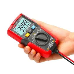
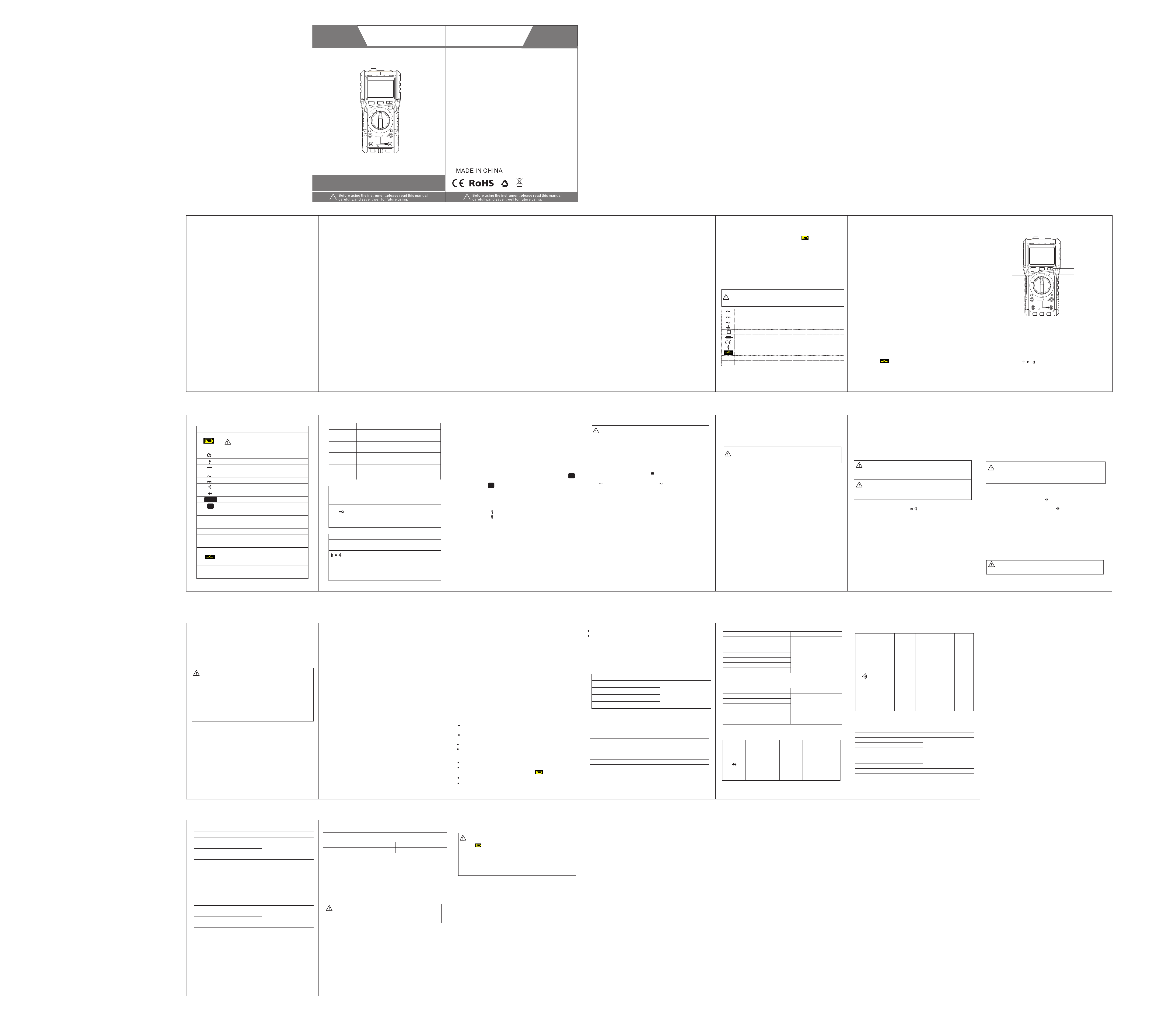
2.1 Schematic diagram of the Instrument
① Non-contact voltage sensing area
② Non-contact voltage indicator light
③ Liquid-crystal display ④ SEL Button
⑤ Hold Button ⑥ Flashlight Button
⑦ V.F.C Button ⑧ Range Rotary Knob
⑨ “V/Ω/Hz%/Live/ / / ℃/℉ ” Input Socket
⑩ 10A Input Socket
⑾ mA/µA Input Socket
⑿ “COM”Socket
Appearance of the instrument
Function selection button, located in the automatic
AC and DC voltage gear and temperature gear. The
function can be switched by pressing this button.
Data hold button
Button for frequency conversion voltage measurement,
located in the automatic AC voltage gear. The frequency
conversion voltage can be measured by pressing this button.
Short press on/off flashlight
Symbol
Description
Positive input terminal of capacitance, diode measurement,
buzzer make-and-break test, temperature measurement,
voltage, resistance, frequency, duty cycle and zero line and
firing line judgment (connected to red measurement probe).
Positive input terminal of Current A, mA (connected to the
red measurement probe).
Positive input terminal of current 10A (connected to the red
measurement probe)
2.5 Accessories
3. Operation instructions
3.1 Normal operation
3.1.1 Reading Hold Mode
The reading hold mode can keep the current reading on the
display. The reading hold mode can be exited by either
changing the measurement function gear or by pressing the
HOLD button only once.
To enter and exit the reading hold mode:
1. Press the“H”button, the reading will be held and the“ ”
symbol will be displayed on the LCD at the same time.
2. Press the“ ”button again to return the instrument to its
normal measurement state.
H
3.1.2 Lighting function
The instrument equipped with the lighting function facilitates
the user to operate in darker lighting conditions. Turn on or
off the flashlight as follows:
1. Press the “ ” button to turn on the light.
2. Press the “ ”button once again to turn off the light.
3.1.3 Frequency conversion voltage measurement function
In the automatic AC and DC voltage gear, press the SEL button y
to switch to the AC voltage gear, and then press the V.F.C button
to enter the frequency conversion voltage measurement function,
which can measure the frequency conversion voltage stably.
3.1.4 Automatic shutdown function
The instrument will emit a ticktack sound to automatically cut
off the power and go to dormancy state after no operation is
taken 15 minutes after starting, press the SEL and V.F.C buttons
in the auto power off mode to restart.
Any voltage above 1000V DC or 750V AC rms can't be measured
to prevent electric shock and/or damage to the instrument.
The voltage of more than 1000V DC or 750V AC rms can't be
imposed between the common terminal and earth to prevent
electric shock and/or damage to the instrument.
1. Rotate the rotary switch to the gear to enter the manual range
measurement mode (press the SEL button to switch between AC
and DC voltage), or rotate the knob to 1000mV, 10V, 100V, 1000V
in , or 1000mV,10V, 100V, 750V of gear, enter manual range
measurement mode to measure DC or AC voltage.
10
3.2 Measurement Guide
The instrument adopts manual/automatic integrated design to
measure voltage or resistance by choosing either auto range
measurement or manual range measurement.
The unit of resistance is ohms (Ω).
The instrument's resistance range is 999.9Ω, 9.999kΩ, 99.99kΩ,
999.9kΩ, 9.999MΩ, 99.99MΩ.
V
2. Connect the black measurement probe and the red measurement
probe to the COM input socket and the V input socket, respectively.
3. Use another two terminals of the measurement probe to measure
the voltage value of the circuit under test. (connection in parallel
with the circuit to be tested)
4. The measured voltage value is read by the liquid crystal display,
and the voltage value can be directly displayed in the automatic
gear. If the manual voltage gear is used, the knob needs to be
rotated to the appropriate gear to read the voltage value. When
measuring AC voltage, the display will display both voltage value
and frequency values at the same time. When measuring DC
voltage,he display will simultaneously display the polarity of the
voltage to which the red measurement probe is connected.
Measuring resistance:
1.Rotate the rotary switch to the gear to the auto range measurement Ω
mode, or rotate the knob to 1000Ω, 10KΩ, 100KΩ, 1000KΩ, 10MΩ,
100MΩ in gear to enter the auto range measurement mode. Ω
2. Connect the black test pen and the red test pen to the COM input
socket and the V / input socket, respectively.
3. Use another two terminals of the measurement probe to measure
the resistance value of the circuit under test.
4. Read the measured resistance value from the LCD. The resistance
value can be directly displayed in the automatic gear. If the manual
resistance gear is used, the knob needs to be rotated to the
appropriate gear to read the resistance value.
Note:
① The measured resistance value on the circuit will usually differ
from the rated value of the resistor.
② When measuring low resistance, please short-circuit the
resistance of the two shorts to read the short of the test leads in
order to keep the accuracy of the measurement. After measuring
the measured resistance, the resistance value needs to be
subtracted.
③ In the 100M gear, it takes a few seconds for stabilizing the reading.
This is normal for high resistance measurements.
④ When the instrument is in the open circuit or the resistance of the
measured object is too large, the display will show “OL”, indicating
that the measured value is out of range.
3.2.3 Testing continuity and diode
The instrument adopts the continuity/diode automatic
identification function.
To avoid damage to the instrument or the device under test,
all power to the circuit under test should be cut off and all
high voltage capacitors should be fully discharged before
measuring the diode.
In order to avoid damage to the instrument under test, all
power to the circuit under test should be cut off and all high
voltage capacitors should be fully discharged before the
buzzer make-and-break test.
3.2.4 Perform continuity or diode measurements
1. Turn the rotary switch to the gear.
2. Connect the black measurement probe and the red
measurement probe to the COM input socket and the V/ Ω input
socket, respectively.
3. Connect the black measurement probe and the red measurement
probe to the two terminals of the object to be tested.
4. If the object to be measured is a diode, place the red and black
measurement probes at the positive and negative terminals of the
diode respectively. The instrument will display the forward bias
value of the diode under test. If the polarity of the measurement
probe is reversed or the polarity of the test point connected to the
diode is reversed, the instrument will display “OL”. In the circuit,
a normal diode should produce a forward voltage drop of 0.5V to
0.8V; however, the reading of reverse bias will depend on the
change in resistance of the other channels between the two
measurement probes.
5.If the resistance of the circuit under test is less than about 100 ,
the instrument will automatically switch to the make-and-break
measurement mode. When the resistance of the circuit under test
is more than about 15, the instrument will automatically switch to
continuity, and the indicator light (green light) induced will be on
for a long time. The buzzer will make a continuous sound. When
the resistance of the circuit under test is between about 15~30,
the indicator light (green light) will flash and the buzzer will make
interrupted sound.
3.2.5 Measuring capacitance
To avoid damage to the instrument or the device under test,
turn off all power to the circuit under test and fully discharge
all high-voltage capacitors before measuring electric
capacity. The DC voltage gear is used to determine that the
capacitors have been discharged.
Measuring capacitance:
1. Turn the rotary switch to the gear .
2. Connect the black measurement probe and red measurement
probe to the COM input socket and input socket respectively.
3. Use another two terminals of the measurement probe to
measure the electric capacity value of the electric capacity to
be tested, and read the measured value from the liquid-crystal
display.
① When measuring large capacitance, it takes time to stabilize
the reading.
② When measuring the electric capacity with the polarity, pay
attention to the corresponding polarity and avoid damage to
the instrument.
Note:
3.2.6 Measurement frequency
Do not measure any frequency of the voltage above
250V DC or AC rms to prevent electric shock and/or
damage to the instrument.
Measuring frequency:
1. Rotate the rotary switch to the AC Voltage or AC Current Range.
2. Connect the black measurement probe and the red measurement
probe to the COM input socket and the Hz input socket, respectively.
3. Measure the frequency value of the circuit under test with
another two terminals of the measurement probe.
4. Read the testing value of AC Volatge or AC Current,the
frequency value show on the LCD simultaneously.
3.2.7 Measuring current
When the open-circuit voltage to the earth exceeds 250V,
be sure to not attempt to make current measurements on
the circuit. If the fuse is burnt out during the measurement,
you may damage the instrument or hurt yourself.
To avoid damage to the instrument or the device under test,
check the fuse of the instrument before making current
measurements. When measuring, use the correct input
socket, function gear and range. When the measurement
probe is plugged into the current input socket, do not
connect the other terminal of the measurement probe in
parallel to any circuit.
The instrument's DC current range is 99.99μA, 99.99mA,
600.0mAand 10.00A, the alternating current measuring range is
99.99mA,600.0mA and 10.00A;
Measuring current:
1. Turn the rotary switch to the appropriate gear.
2. Connect the black measurement probe to the COM input
socket. Connect the red measurement probe to the uA/mA
input socket if the measured current is less than 600mA; if the
measured current is between 600mA and 10A, connect the red
measurement probe to the 10A input socket.
3. Disconnect the circuit to be tested. Connect the black
measurement probe to the terminal of the disconnected circuit
(with lower voltage) and the red measurement probe to the
terminal of the disconnected circuit (with higher voltage).
4. Connect the power to the circuit and read the displayed reading.
In the AC current gear, the screen simultaneously displays the
current value and frequency. If the display only shows "OL",
which means that the input exceeds the selected range, the
rotary switch should be placed at a higher range.
Rotate the rotary switch to the NCV gear to close the top of the
instrument to the conductor. If the instrument detects the AC
voltage, the instrument will light the corresponding signal strength
indicator according to the detected signal strength. When the
sensed voltage is low, the screen will display --- L, the green
indicator light is on for a long time. When the sensed voltage is
high, the screen displays -- H, the two red indicators light up, and
the buzzer sounds an alarm at different frequencies.
3.2.8 NCV test (non-contact voltage detection)
Note:
1. Even if no indication exists, the voltage may still exist. Do not
rely on non-contact voltage detectors to determine if a wire has
a voltage. Detection operations may be affected by factors such
as socket design, insulation thickness and type.
2. When the voltage is entered into the input terminal of the
instrument, the voltage sensing indicator may also be bright
due to the presence of induced voltage.
3. Interference sources in the external environment (such as
flashing light, motor, etc.) may trigger non-contact voltage
detection by mistake.
1. Rotate the rotary switch to the Live gear.
3.2.9 Live Line Test
2. Connect the red measurement probe to the V input socket.
3.Insert a single measurement probe into the power socket L jack
or close to the live wire. If the instrument detects the AC voltage,
it will judge whether the voltage is a firewire according to the
detected signal strength. If it is judged to be a live line, the
display will send display LIVE and the green indicator light will
be on, the buzzer will send an alarm with different intensities.
Set the range switch to °C/°F gear and the screen will display
normal temperature.
3.2.10 Measurement of temperature and humidity
The default unit of this gear is °C, press SEL button to
switch to °F.
15
4 Technical indicators
4.1 Comprehensive indicator
Environmental conditions for usage:
600V CAT IV and 1000V CAT. III Pollution degree: 2
Altitude above sea level < 2000 m.
Temperature and humidity in the working environment:
0~40 OC (<80% RH, it isn't considered when <10°C).
Storage environment temperature and humidity:
-10~60 OC (when <70% RH, remove the battery).
Maximum allowable voltage between the measuring terminal
and the earth: 1000V DC or 750V AC RMS
Protection of the fuse tube: mA gear: fuse tube FF
600mA/250V; A-gear fuse tube FF 10A/250V
Conversion rate: about 3 times / second
Display: 9999 counts displayed by LCD. The unit symbol is
automatically displayed according to the measurement
function gear.
Overrange indication: The LCD will display “OL”.
Indication for low voltage battery: When the battery voltage is
lower than the normal working voltage, “ ” will be displayed.
Indication of input polarity: “-” is automatically displayed.
Power supply: 2 x 1. 5V AA battery
External dimensions: 185x88x52mm
Weight: about 350g (including battery).
4.2 Precision Index
Accuracy: ±(% reading + word), the warranty period is one year
from the date of delivery.
Reference conditions: ambient temperature 18 ° C to 28 ° C,
relative humidity is not more than 80%
4.2.1 DC voltage
Resolution Accuracy
Input impedance: 10MΩ
Maximum input voltage: 1000Vdc or 750Vac rms.
Input impedance: 10MΩ
Maximum input voltage: 1000Vdc or 750Vac rms.
4.2.2 AC voltage
Measuring range Resolution Accuracy
Measuring range Resolution Accuracy
±(0.8% reading +3 digits)
±(1. 2% reading +5 digits)
4.2.4 Resistance
4.2.5 Diode
Diode test
Resolution Test condition
Forward DC
current: about 1mA;
open-circuit
voltage: about 3.2V.
The display shows
an approximation of
the forward voltage
drop of the diode.
4.2.6 Buzzer and continuity
The built-in
buzzer sounds
continuously and
the green indicator
light is on when the
resistance is less
than15Ω.The buzzer
will give an alarm
intermittently, and
the green indicator
light flashes when
the measured
resistance is
between15Ω
and30Ω.
Measuring
range
Function
Resolution
Test
condition
Description
Overload protection: 600V DC/AC
Open-
circuit
voltage:
about 1V
4.2.7 Capacitance
Measuring range Resolution Accuracy
Measuring range
4.2.8 Direct current
Resolution Accuracy
±(1. 2% reading +3 digits)
Maximum input current: mA gear: 600mA DC or AC RMS;
10A gear: 10A DC or AC RMS
When the measured current is greater than 5A, the continuous
measurement time is no longer than 10 seconds, and the current
measurement must be stopped for 1 minute after the measurement.
Measuring range Resolution Accuracy
4.2. 9 Alternating current
±(1% reading +3 digits)
±(1. 5% reading +3 digits)
Overload protection: mA range fuse (FF630mA/250V);
10A range fuse (FF10A/250V ).
Maximum input current: mA gear: 600mA DC or AC RMS;
10A gear: 10A DC or AC RMS
When the measured current is greater than 5A, the continuous
measurement time is no longer than 15 seconds, and the current
measurement must be stopped for 1 minute after the measurement.
Frequency response: 40Hz-1KHz, true RMS
4.2. 10 Temperature
5. Instrument maintenance
This section provides basic maintenance information, including
instructions for replacing the fuse and replacing the battery.
Do not attempt to repair the instrument unless you are an
experienced serviceman with relevant calibration, performance
testing, and maintenance information.
5.1 General Maintenance
To avoid electric shock or damage to the instrument, do not
wet the inside of the instrument. The connection wire
between the measurement probe and input signal must be
removed before opening the case or battery cover.
Regularly clean the case of the instrument with a damp cloth and
a small amount of detergent. Do not use abrasives or chemical
solvents. Input sockets that are dirty or damp may affect readings.
Cleaning the input socket:
① Turn off the instrument and pull all the measurement probes out
of the input socket.
② Remove any dirt from the socket.
③ Use a new cotton ball dipped in detergent or lubricant to clean
each socket. The lubricant can be used to prevent socket
contamination relevant to the moisture.
5.2 Replacing the battery and fuse
Please replace the battery according to the following steps:
1. Turn off the power of the instrument.
2. Pull all the measurement probes out of the input socket.
3. Loosen the screws that secure the battery cover with a
screwdriver.
4. Remove the cover of the battery.
5. Remove the old battery or damaged fuse.
6. Replace with a new 2 x 1. 5V AA battery or a new fuse tube
7. Install the battery cover and tighten the screws.
⑥
⑦
⑿
③
①
⑾
④
⑧
②
⑨
⑩
⑤
OFF
NCV
1000
100K
1000K
10M
100M
℃/℉
100μ
100m
600m
10A
600m
100m
1000m
10
100
1000
1000m
10
100
750
Live
10A
10000 COUNTS TRUE RMS DIGITAL MULTIMETER
10A
mA
HOLD
SEL.
COM
MAX 1 0A
FUS ED
MAX 6 00mA
FUS ED
MAX
750 V
100 0V
V
V
Ω
A
A
10K
μA
Ω
V
Live
℃/℉
Hz%
1000V CAT
600V CAT IV
Ⅲ
Ω
V
Hz
Hz
Hz%
V.F.C
Indicates the auto ranging mode.
AUTO
Automatic range
AUTO
Note:
① In the 1000mV range of DC and AC, even if the measurement
probe isn't entered or connected, the reading will be displayed on
the instrument. In this case, short-circuit the “V ”and“COM”
terminals to make the instrument display return to zero.
② Under the AC voltage function of the auto range, press the V.F.C
button to measure the AC frequency conversion voltage.
You can also insert the red plug of the thermocouple into the
°C terminal and the black plug into the COM jack. When the
reading is stable, the temperature value can be read directly
from the display.
Temperature coefficient: 0.1 accuracy / OC (<18 OC or >28 OC).
9.999Hz
99.99Hz
999.9Hz
0.001Hz
0.01Hz
0.1Hz
0.001KHz
9.999KHz
99.99KHz
999.9KHz
0.01KHz
0.1KHz
9.999KHz
0.001MHz
4.2.3 Frequency
Measuring range Resolution Accuracy
±(1% reading +3 digits)
Range of Input voltage: 200mV-10V ac RMS
Overload protection: 600V DC/AC
9.999nF
99. 99nF
999. 9nF
9.999μF
99. 99μF
999. 9μF
9.999mF
0.001nF
0.01nF
0.1nF
1nF
10nF
100nF
1μF
99. 99mF
10μF
±(4.0% reading +30digits)
±(4.0% reading +3digits)
±(5.0% reading +3digits)
℃
1℃ -2 0℃~1 000 ℃
℉
1℉ -4℉~1832℉
Measuring
range
Resolution
Accuracy
±(1.0% reading +3 digits)
±(1.0% reading +3 digits)