CONDENSING UNIT
Air Conditioning
Installation & Service Reference
is a registered trademark of Maytag Corporation or its related
companies and is used under license. All rights reserved.
© 2021-2022
Daikin Comfort Technologies Manufacturing, L.P.
19001 Kermier Rd. Waller, TX 77484
www.goodmanmfg.com -or- www.amana-hac.com
P/N: IOG-4036B Date: December 2022
IMPORTANT SAFETY INSTRUCTIONS
The following symbols and labels are used throughout this
manual to indicate immediate or potential safety hazards.
It is the owner’s and installer’s responsibility to read
and comply with all safety information and instructions
accompanying these symbols. Failure to heed safety
information increases the risk of personal injury, property
damage, and/or product damage.
WARNING
High Voltage!
Disconnect all power before servicing or
installing this unit. Multiple power sources may
be present. Failure to do so may cause property
damage, personal injury or death.
ONLY PERSONNEL THAT HAVE BEEN TRAINED TO INSTALL,
ADJUST, SERVICE, MAINTENANCE OR REPAIR
(HEREINAFTER, “SERVICE”) THE EQUIPMENT SPECIFIED IN
THIS MANUAL SHOULD
SERVICE THE EQUIPMENT. THE MANUFACTURER WILL
NOT BE RESPONSIBLE FOR ANY INJURY OR PROPERTY
DAMAGE ARISING FROM IMPROPER SERVICE OR SERVICE
PROCEDURES. IF YOU SERVICE THIS UNIT, YOU ASSUME
RESPONSIBILITY FOR ANY INJURY OR PROPERTY
DAMAGE WHICH MAY RESULT. IN ADDITION, IN
JURISDICTIONS THAT REQUIRE ONE OR MORE LICENSES
TO SERVICE THE EQUIPMENT SPECIFIED IN THIS
MANUAL, ONLY LICENSED PERSONNEL SHOULD SERVICE
THE EQUIPMENT.
IMPROPER INSTALLATION, ADJUSTMENT, SERVICING,
MAINTENANCE OR REPAIR OF THE EQUIPMENT SPECIFIED
IN THIS MANUAL, OR ATTEMPTING TO INSTALL, ADJUST,
SERVICE OR REPAIR THE EQUIPMENT SPECIFIED IN THIS
MANUAL WITHOUT PROPER TRAINING MAY RESULT IN
PRODUCT DAMAGE, PROPERTY DAMAGE, PERSONAL
INJURY OR DEATH.
WARNING
WARNING
DO NOT BYPASS SAFETY DEVICES
SHIPPING INSPECTION
Always keep the unit upright; laying the unit on its side
or top may cause equipment damage. Shipping damage,
and subsequent investigation is the responsibility of
the carrier. Verify the model number, specications,
electrical characteristics, and accessories are correct
prior to installation. The distributor or manufacturer will not
accept claims from dealers for transportation damage or
installation of incorrectly shipped units.
CODES & REGULATIONS
This product is designed and manufactured to comply
with national codes. Installation in accordance with such
codes and/or prevailing local codes/regulations is the
responsibility of the installer. The manufacturer assumes
no responsibility for equipment installed in violation of any
codes or regulations. Rated performance is achieved after
20 hours of operation.
Rated performance is delivered at the specied airow.
See outdoor unit specication sheet for split system models
or product specication sheet for packaged and light
commercial models. Specication sheets can be found at
www.goodmanmfg.com for Goodman® brand products or
www.amana-hac.com for Amana® brand products. Within
either website, please select the residential or commercial
products menu and then select the submenu for the type
of product to be installed, such as air conditioners or heat
pumps, to access a list of product pages that each contain
links to that model’s specication sheet.
The United States Environmental Protection Agency
(EPA) has issued various regulations regarding the
introduction and disposal of refrigerants. Failure to
follow these regulations may harm the environment
and can lead to the imposition of substantial nes.
Should you have any questions please contact the local
oce of the EPA.
If replacing a condensing unit or air handler, the system
must be manufacturer approved and Air Conditioning,
Heating and Refrigeration Institute (AHRI) matched.
NOTE: Installation of unmatched systems is
strongly discouraged.
2
Outdoor units are approved for operation above 55°F in
cooling mode. Operation below 55°F requires the use of an
approved low ambient kit. Note: LAKT01 Low ambient kit
cannot be used with outdoor units containing ECM motors.
Damage to the unit caused by operating the unit in a
structure that is not complete (either as part of new
construction or renovation) is not covered under the
warranty.
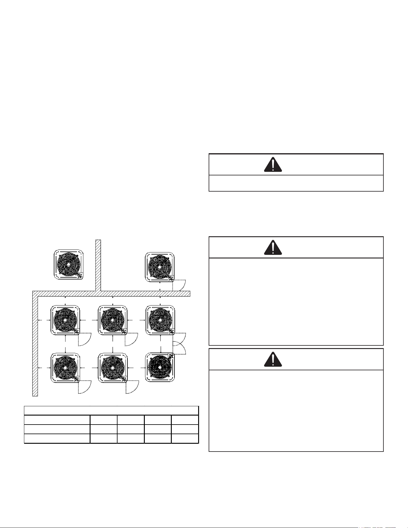
INSTALLATION CLEARANCES
Special consideration must be given to location of the
condensing unit(s) in regard to structures, obstructions,
other units, and any/all other factors that may interfere with
air circulation. Where possible, the top of the unit should
be completely unobstructed; however, if vertical conditions
require placement beneath an obstruction there should
be a minimum of 60 inches between the top of the unit
and the obstruction(s). The specied dimensions meet
requirements for air circulation only. Consult all appropriate
regulatory codes prior to determining nal clearances.
Another important consideration in selecting a location for
the unit(s) is the angle to obstructions. Either side adjacent
the valves be placed toward the structure provided the
side away from the structure maintains minimum service
clearance. Corner installations are strongly discouraged.
OK!
OK!
AA AAA
A
CC
C
C
OK!
OK!
OK!
OK!
NOT
RECOMMENDED
AA
AA
AA
AA
AA
B B B
B
Model Type A B C AA
Residential 10" 10" 18" 20"
Light Commercial 12" 12" 18" 24"
Minimum Airflow Clearance
This unit can be located at ground oor level or on at
roofs. At ground oor level, the unit must be on a solid,
level foundation that will not shift or settle. To reduce the
possibility of sound transmission, the foundation slab
should not be in contact with or be an integral part of the
building foundation. Ensure the foundation is sucient to
support the unit. A concrete slab raised above ground level
provides a suitable base.
ROOFTOP INSTALLATIONS
If it is necessary to install this unit on a roof structure,
ensure the roof structure can support the weight and that
proper consideration is given to the weather-tight integrity
of the roof. Since the unit can vibrate during operation,
sound vibration transmission should be considered when
installing the unit. Vibration absorbing pads or springs can
be installed between the condensing unit legs or frame and
the roof mounting assembly to reduce noise vibration.
WARNING
To avoid possible injury, explosion or death, practice safe
handling of refrigerants.
SAFE REFRIGERANT HANDLING
While these items will not cover every conceivable
situation, they should serve as a useful guide.
WARNING
Refrigerants are heavier than air. They can “push out” the
oxygen in your lungs or in any enclosed space. To avoid
possible difficulty in breathing or death:
• Never purge refrigerant into an enclosed room or
space. By law, all refrigerants must be reclaimed.
• If an indoor leak is suspected, thoroughly ventilate the
area before beginning work.
• Liquid refrigerant can be very cold. To avoid possible
frostbite or blindness, avoid contact and wear gloves
and goggles. If liquid refrigerant does contact your
skin or eyes, seek medical help immediately.
• Always follow EPA regulations. Never burn refrigerant,
as poisonous gas will be produced.
WARNING
To avoid possible explosion:
• Never apply flame or steam to a refrigerant cylinder. If
you must heat a cylinder for faster charging, partially
immerse it in warm water.
• Never fill a cylinder more than 80% full of liquid
refrigerant.
• Never add anything other than R-22 to an R-22 cylinder
or R-410A to an R-410A cylinder. The service equipment
used must be listed or certified for the type of
refrigerant used.
• Store cylinders in a cool, dry place. Never use a
cylinder as a platform or a roller.
3
WARNING
To avoid possible explosion, use only returnable (not
disposable) service cylinders when removing refrigerant
from a system.
• Ensure the cylinder is free of damage which could lead
to a leak or explosion.
• Ensure the hydrostatic test date does not exceed 5
years.
• Ensure the pressure rating meets or exceeds 400 psig.
When in doubt, do not use cylinder.
Refrigerant Lines
CAUTION
The compressor POE oil for R-410A units is extremely
susceptible to moisture absorption and could cause
compressor failure. Do not leave system open to atmosphere
any longer than necessary for installation.
Use only refrigerant grade (dehydrated and sealed)
copper tubing to connect the condensing unit with the
indoor evaporator. After cutting the tubing, install plugs to
keep refrigerant tubing clean and dry prior to and during
installation. Tubing should always be cut square keeping
ends round and free from burrs. Clean the tubing to
prevent contamination.
Do NOT let refrigerant lines come in direct contact with
plumbing, ductwork, oor joists, wall studs, oors, and
walls. When running refrigerant lines through a foundation
or wall, openings should allow for sound and vibration
absorbing material to be placed or installed between tubing
and foundation. Any gap between foundation or wall and
refrigerant lines should be lled with a pliable silicon-
based caulk, RTV or a vibration damping material. Avoid
suspending refrigerant tubing from joists and studs with
rigid wire or straps that would come in contact with the
tubing. Use an insulated or suspension type hanger. Keep
both lines separate and always insulate the suction line.
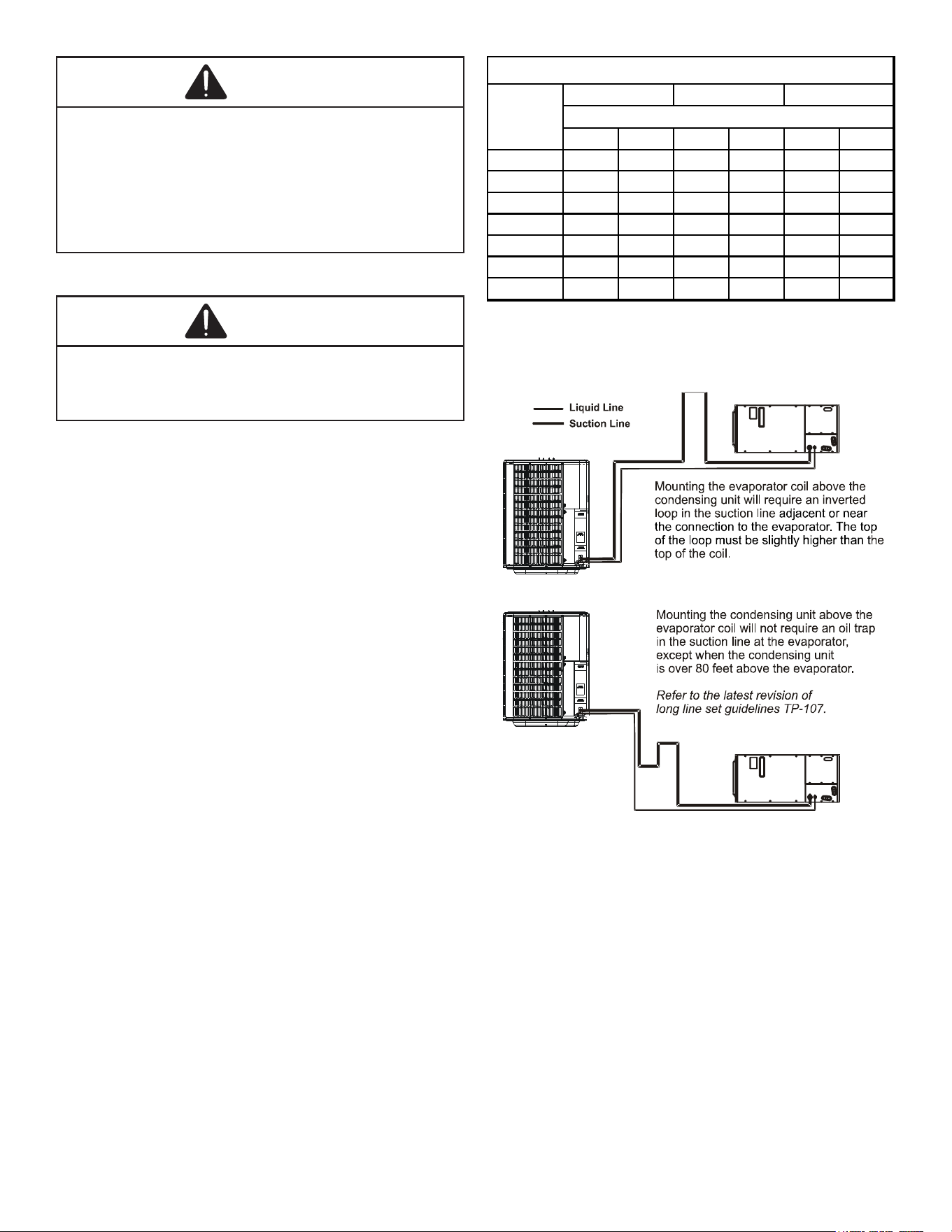
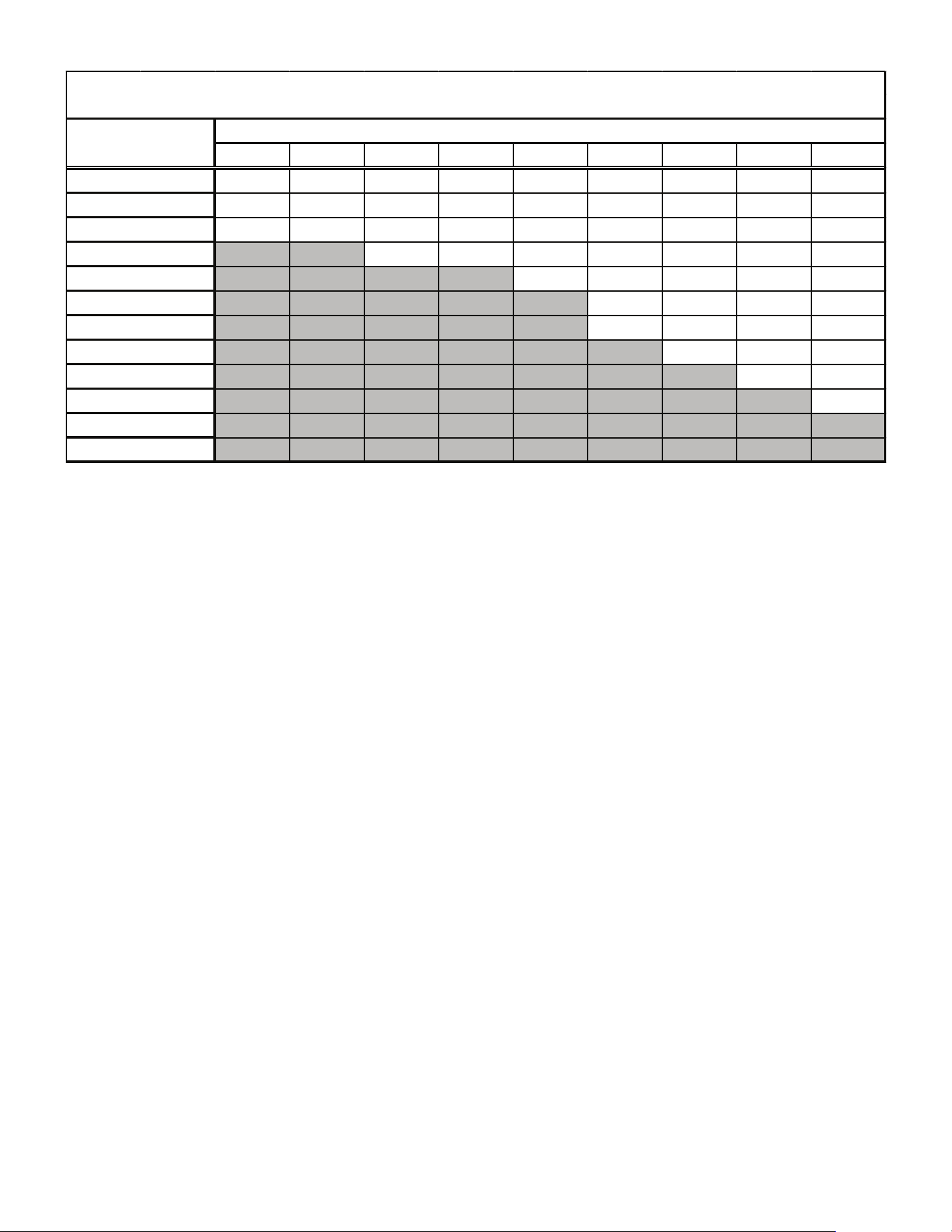
These sizes are recommended for line lengths of 79 feet
or less to obtain optimum performance. For alternate line
sizing options or runs of more than 79 feet, refer to TP-107
R-410A Long Line Set Application Guidelines or contact
your distributor for assistance.
Cond
Unit
Tons Suct Liq Suct Liq Suct Liq
1 1/2 5/8
1/4 3/4 3/8
3/4 3/8
2 5/8 1/4 3/4 3/8
3/4 3/8
2 1/2 5/8
1/4 3/4 3/8 7/8
3/8
3 3/4 3/8 7/8 3/8 1 1/8 3/8
3 1/2 7/8 3/8 1 1/8 3/8 1 1/8 3/8
4 7/8 3/8 1 1/8 3/8 1 1/8 3/8
5 7/8 3/8 1 1/8
3/8 1 1/8 3/8
Line Diameter (In. OD)
RECOMMENDED INTERCONNECTING TUBING (Ft)
0-24
25-49
50-79*
*
Lines greater than 79 f eet in length or v ertical elev ation changes more than
50 f eet refer to TP-107 R-410A Long Line Set Application Guidelines or
contact your distributor for assistance.
Insulation is necessary to prevent condensation from
forming and dropping from the suction line. Armex (or
satisfactory equivalent) with 3/8” min. wall thickness is
recommended. In severe conditions (hot, high humidity
areas) 1/2” insulation may be required. Insulation must be
installed in a manner which protects tubing from damage
and contamination.
Existing Line Sets
Where possible, drain as much residual compressor
oil from existing systems, lines, and traps; pay close
attention to low areas where oil may collect. Use of an
approved ushing agent is recommended followed by a
nitrogen purge to remove any remaining ushing agent
from the lines or indoor coil. Replacement of indoor coil is
recommended.
4
NOTE: If using existing indoor coil and changing
refrigerant types, ensure the indoor coil and
metering device are compatible with the type
of refrigerant being used. If new indoor coil is
required check spec sheet or AHRI for approved
coil. If system is being replaced due to compressor
electrical failure, assume acid is in system. Refer
to Service Procedure S-115 Compressor Burnout
in service manual for clean-up procedure.
Burying Refrigerant Lines
If burying refrigerant lines can not be avoided, use the
following checklist.
1. Insulate liquid and suction lines separately.
2. Enclose all underground portions of the refrigerant
lines in waterproof material (conduit or pipe) sealing
the ends where tubing enters/exits the enclosure.
3. If the lines must pass under or through a concrete
slab, ensure lines are adequately protected and
sealed.
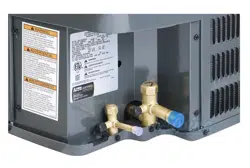
Refrigerant Line Connections
IMPORTANT: To avoid overheating the service
valve, TXV valve, or filter drier while brazing,
wrap the component with a wet rag, or use a
thermal heat trap compound. Be sure to follow
the manufacturer’s instruction when using the
heat trap compound. Note: Remove Schrader
valves from service valves before brazing tubes
to the valves. Use a brazing alloy of 2% minimum
silver content. Do not use flux.
Torch heat required to braze tubes of various sizes is
proportional to the size of the tube. Tubes of smaller size
require less heat to bring the tube to brazing temperature
before adding brazing alloy. Applying too much heat to any
tube can melt the tube. Service personnel must use the
appropriate heat level for the size of the tube being brazed.
NOTE: The use of a heat shield when brazing is
recommended to avoid burning the serial plate or
the finish on the unit.
1. The ends of the refrigerant lines must be cut square,
deburred, cleaned, and be round and free from nicks
or dents. Any other condition increases the chance of
a refrigerant leak.
2. “Sweep” the refrigerant line with nitrogen or inert gas
during brazing to prevent the formation of copper-
oxide inside the refrigerant lines. The POE oils used
in R-410A applications will clean any copper-oxide
present from the inside of the refrigerant lines and
spread it throughout the system. This may cause a
blockage or failure of the metering device.
3. After brazing, quench the joints with water or a wet
cloth to prevent overheating of the service valve.
4. Ensure the lter drier paint nish is intact after
brazing. If the paint of the steel lter drier has
been burned or chipped, repaint or treat with a rust
preventative. This is especially important on suction
line lter driers which are continually wet when the
unit is operating.
NOTE: Be careful not to kink or dent refrigerant
lines. Kinked or dented lines will cause poor
performance or compressor damage.
Do NOT make nal refrigerant line connection until plugs
are removed from refrigerant tubing.
NOTE: Before brazing, verify indoor piston size by
checking the piston kit chart packaged with indoor
unit.
Standing Pressure Test (Recommended before
System Evacuation)
WARNING
To avoid the risk of fire or explosion, never use oxygen,
high pressure air or flammable gases for leak testing of a
refrigeration system.
WARNING
To avoid possible explosion, the line from the nitrogen
cylinder must include a pressure regulator and a pressure
relief valve. The pressure relief valve must be set to open at
no more than 450 psig.
Using dry nitrogen, pressurize the system to 450 PSIG.
Allow the pressure to stabilize and hold for 15 minutes
(minimum). If the pressure does not drop below 450 PSIG
the system is considered leak free. Proceed to system
evacuation using the Deep Vacuum Method. If after 15
minutes the pressure drops below 450 PSIG follow the
procedure outlined below to identify system leaks. Repeat
the Standing Pressure Test.
Leak Testing (Nitrogen or Nitrogen-Traced)
WARNING
To avoid the risk of fire or explosion, never use oxygen,
high pressure air or flammable gases for leak testing of a
refrigeration system.
WARNING
To avoid possible explosion, the line from the nitrogen
cylinder must include a pressure regulator and a pressure
relief valve. The pressure relief valve must be set to open at
no more than 450 psig.
5
Leak test the system using dry nitrogen and soapy
water to identify leaks. If you prefer to use an electronic
leak detector, charge the system to 10 PSIG with the
appropriate system refrigerant (see Serial Data Plate
for refrigerant identication). Do not use an alternative
refrigerant. Using dry nitrogen nish charging the system
to 450 PSIG. Apply the leak detector to all suspect areas.
When leaks are discovered, repair the leaks, and repeat
the pressure test. If leaks have been eliminated proceed to
system evacuation.
System Evacuation
Condensing unit liquid and suction valves are closed to
contain the charge within the unit. The unit is shipped with
the valve stems closed and caps installed. Do not open
valves until the system is evacuated.
WARNING
REFRIGERANT UNDER PRESSURE!
Failure to follow proper procedures may cause property
damage, personal injury or death.
NOTE: Scroll compressors should never be used
to evacuate or pump down a heat pump or air
conditioning system.
CAUTION
Prolonged operation at suction pressures less than 20 psig
for more than 5 seconds will result in overheating of the
scrolls and permanent damage to the scroll tips, drive
bearings and internal seal.
Deep Vacuum Method (Recommended)
The Deep Vacuum Method requires a vacuum pump
rated for 500 microns or less. This method is an eective
and ecient way of assuring the system is free of non-
condensable air and moisture. As an alternative, the Triple
Evacuation Method is detailed in the Service Manual for
this product model.
It is recommended to remove the Schrader Cores from the
service valves using a core-removal tool to expedite the
evacuation procedure.
1. Connect the vacuum pump, micron gauge, and
vacuum rated hoses to both service valves.
Evacuation must use both service valves to eliminate
system mechanical seals.
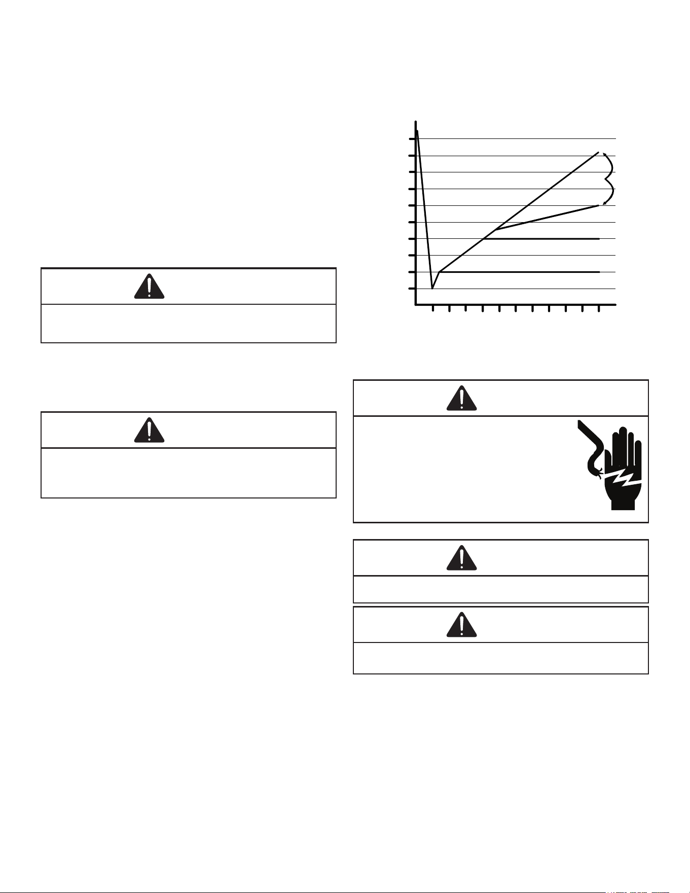
2. Evacuate the system to less than 500 microns.
3. Isolate the pump from the system and hold vacuum
for 10 minutes (minimum). Typically, pressure will rise
slowly during this period. If the pressure rises to less
than 1000 microns and remains steady, the system is
considered leak-free; proceed to system charging and
startup.
4. If pressure rises above 1000 microns but holds steady
below 2000 microns, non-condensable air or moisture
may remain or a small leak is present. Return to step
2: If the same result is achieved check for leaks and
repair. Repeat the evacuation procedure.
5. If pressure rises above 2000 microns, a leak is
present. Check for leaks and repair. Repeat the
evacuation procedure.
5000
4500
4000
3500
3000
2500
2000
1500
1000
500
0 1 2 3 4 5 6 7 8 9
10
LEAK(S)
PRESENT
MINUTES
V
ACUUM
IN
MICRONS
CONDENSIBLES OR SMALL
LEAK PRESENT
NO LEAKS
NO CONDENSIBLES
ELECTRICAL CONNECTIONS
WARNING
HIGH VOLTAGE!
Disconnect ALL power before servicing.
Multiple power sources may be present.
Failure to do so may cause property damage,
personal injury or death due to electric
shock. Wiring must conform with NEC or CEC
and all local codes. Undersized wires could
cause poor equipment performance, equipment
damage or fire.
WARNING
To avoid the risk of fire or equipment damage, use copper
conductors.
NOTICE
Units with rotary or reciprocating compressors and non-
bleed TXV’s require a Hard Start Kit.
The condensing unit rating plate lists pertinent electrical
data necessary for proper electrical service and
overcurrent protection. Wires should be sized to limit
voltage drop to 2% (max.) from the main breaker or fuse
panel to the condensing unit. Consult the NEC, CEC, and
all local codes to determine the correct wire gauge and
length.
Local codes often require a disconnect switch located near
the unit; do not install the switch on the unit. Refer to the
installation instructions supplied with the indoor furnace/
air handler for specic wiring connections and indoor unit
6
conguration. Likewise, consult the instructions packaged
with the thermostat for mounting and location information.
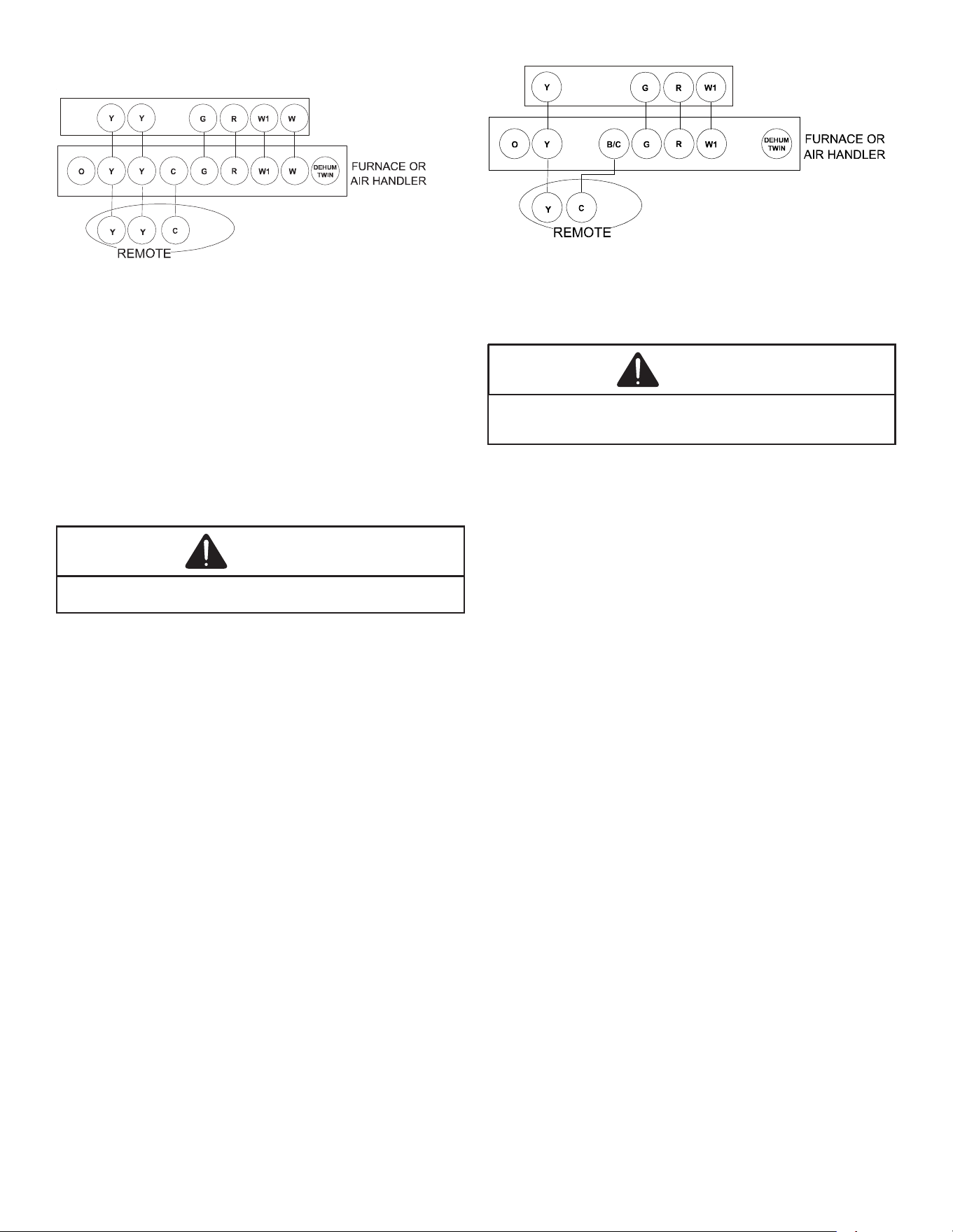
THERMOSTAT
2-STAGE HEATING WITH
2-STAGE COOLING
Two-Stage Thermostat
with Three Low Voltage Wires to
Remote
2
2
2
1
2
1
1
2
Two-Stage Thermostat
with Three Low Voltage Wires to Remote
Overcurrent Protection
The following overcurrent protection devices are approved
for use.
• Time delay fuses
• HACR type circuit breakers
These devices have sucient time delay to permit the
motor-compressor to start and accelerate its load.
Three Phase Compressor Rotation
CAUTION
Use care when handling scroll compressors. Dome
temperatures could be hot.
Three phase compressors are power phase dependent
and can rotate in either direction.
Verify proper rotation for three phase compressors by
ensuring the suction pressure drops and discharge
pressure rises when the compressor is energized.
NOTE: When operated in reverse, a three phase
scroll compressors is noisier and its current
draw substantially reduced compared to marked
values.
To correct, disconnect power and switch any two leads at
the unit contactor and re-observe.
High Voltage Connections
Route power supply and ground wires through the high
voltage port and terminate in accordance with the wiring
diagram provided inside the control panel cover.
Low Voltage Connections
Condensing unit control wiring requires 24 Volt minimum,
25VA service from the indoor transformer. Low voltage
wiring for two-stage units depends on the thermostat used
and the number of control wires between the indoor unit
and the condensing unit. Route control wires through the
low voltage port and terminate in accordance with the
wiring diagram provided inside the control panel cover.
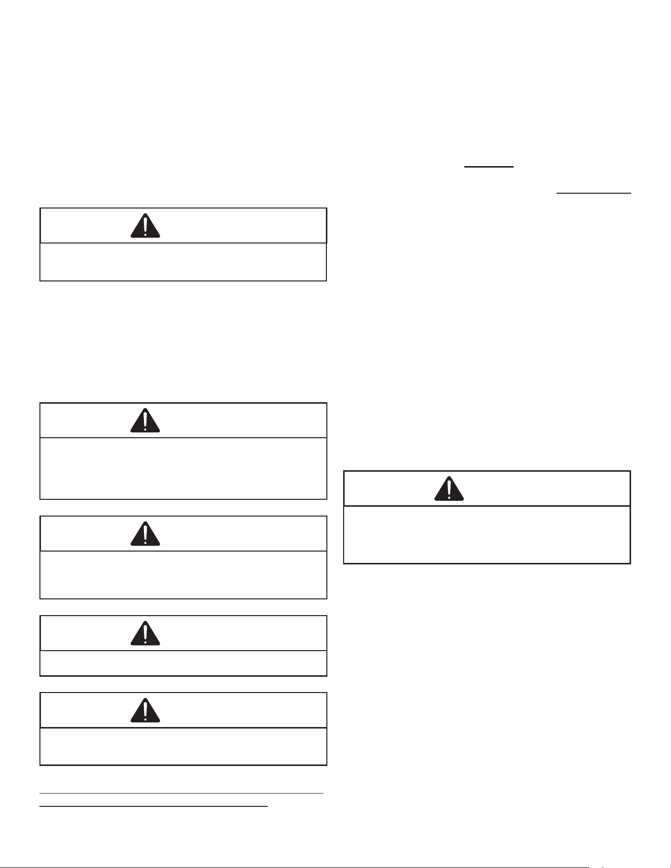
THERMOSTAT
SINGLE-STAGE HEATING
WITH
SINGLE-STAGE COOLING
Single-Stage Thermostat
with Two Low Voltage Wires to Remote
SYSTEM START UP
CAUTION
POSSIBLE REFRIGERANT LEAK
To avoid a possible refrigerant leak, open the service valves
until the top of the stem is 1/8” from the retainer.
When opening valves with retainers, open each valve
only until the top of the stem is 1/8” from the retainer. To
avoid loss of refrigerant, DO NOT apply pressure to the
retainer. When opening valves without a retainer remove
service valve cap and insert a hex wrench into the valve
stem and back out the stem by turning the hex wrench
counterclockwise. Open the valve until it contacts the rolled
lip of the valve body.
NOTE: These are not back-seating valves. It is not
necessary to force the stem tightly against the
rolled lip.
NOTE: Power must be supplied to the outdoor
units containing ECM motors before the power is
applied to the indoor unit. Sending a low voltage
signal without high voltage power present at
the outdoor unit can cause malfunction of the
control module on the ECM motor.
Adequate refrigerant charge for the matching HSVTC
evaporator coil and 15 feet of lineset is supplied with
the condensing unit. If using evaporator coils other than
HSVTC coil, it may be necessary to add or remove
refrigerant to attain proper charge. If line set exceeds 15
feet in length, refrigerant should be added at .6 ounces per
foot of liquid line.
NOTE: Charge should always be checked using
superheat when using a piston and subcooling
when using TXV equipped indoor coil to verify
proper charge.
Break vacuum by fully opening liquid service valve.
After the refrigerant charge has bled into the system,
open the suction service valve. The service valve cap is
the secondary seal for the valves and must be properly
tightened to prevent leaks. Make sure cap is clean and
apply refrigerant oil to threads and sealing surface on
7
inside of cap. Tighten cap nger-tight and then tighten
additional 1/6 of a turn (1 wrench at), or to the following
specication, to properly seat the sealing surfaces.
1. 3/8” valve to 5 - 10 in-lbs
2. 5/8” valve to 5 - 20 in-lbs
3. 3/4” valve to 5 - 20 in-lbs
4. 7/8” valve to 5 - 20 in-lbs
Do not introduce liquid refrigerant from the cylinder into
the crankcase of the compressor as this may damage the
compressor.
CAUTION
POSSIBLE REFRIGERANT LEAK
To avoid a possible refrigerant leak, open the service valves
until the top of the stem is 1/8” from the retainer.
1. Break vacuum by fully opening liquid and suction
base valves.
2. Set thermostat to call for cooling. Check indoor and
outdoor fan operation and allow system to stabilize
for 10 minutes for xed orices and 20 minutes for
expansion valves.
Charge Verification
WARNING
REFRIGERANT UNDER PRESSURE!
• Do not overcharge system with refrigerant.
• Do not operate unit in a vacuum or at negative pressure.
Failure to follow proper procedures may cause property
damage, personal injury or death.
CAUTION
Use refrigerant certified to AHRI standards. Used
refrigerant may cause compressor damage. Most portable
machines cannot clean used refrigerant to meet AHRI
standards.
NOTICE
Violation of EPA regulations may result in fines or other
penalties.
CAUTION
Damage to the unit caused by operating the compressor with
the suction valve closed is not covered under the warranty
and may cause serious compressor damage.
Final Charge Adjustment
Airow and Total Static Pressure for the indoor unit should
be veried before attempting to charge system.
1. Total static pressure is .5” WC or less.
2. Airow is correct for installed unit.
3. Airow tables are in the installation manual and Spec
Sheet for Indoor Unit.
4. Complete charging information are in Service Manual
RS6200006.
NOTE: Superheat adjustments should not be made
until indoor ambient conditions have stabilized.
This could take up to 24 hours depending on
indoor temperature and humidity. Before checking
superheat run the unit in cooling for 10-15 minutes
or until refrigerant pressures stabilize. Use the
following guidelines and methods to check unit
operation and ensure that the refrigerant charge
is within limits.
The outdoor temperature must be 60°F or higher. Set the
room thermostat to COOL, fan switch to AUTO, and set the
temperature control well below room temperature.
Units matched with indoor coils equipped with a non-
adjustable TXV should be charged by Subcooling only.
Superheat on indoor coils with adjustable TXV valves are
factory set and no adjustment is normally required during
startup. Only in unique applications due to refrigerant
line length, dierences in height between the indoor
and outdoor unit and refrigerant tubing sizes or poor
performance should Superheat setting require adjustment.
These adjustments should only be performed by
qualied service personnel. For detailed charge and TXV
adjustments refer to the appropriate Service Manual.
Fixed Orifice
CAUTION
To prevent personal injury, carefully connect and
disconnect manifold gauge hoses. Escaping liquid
refrigerant can cause burns. Do not vent refrigerant into
the atmosphere. Recover all refrigerant during system
repair and before final unit disposal.
1. Purge gauge lines. Connect service gauge manifold
to base-valve service ports. Run system at least 10
minutes to allow pressure to stabilize.
2. Temporarily install a thermometer 4-6” from
the compressor on the suction line. Ensure the
thermometer makes adequate contact and is insulated
for best possible readings. Use vapor temperature to
determine superheat.
3. Refer to the superheat table provided for proper
system superheat. Add charge to lower superheat or
recover charge to raise superheat.
4. Disconnect manifold set, installation is complete.
Superheat Formula = Suct. Line Temp. - Sat. Suct.
Temp.
8
55 57 59 61 63 65 67 69 71
10 13 17 20 23 26 29 30 31
8 11 14 16 19 22 26 27 29
5 8 10 13 15 19 23 24 25
--- --- 6 9 11 15 20 21 23
--- --- --- --- 7 12 17 18 20
--- --- --- --- --- 8 13 15 16
--- --- --- --- --- 7 10 11 13
--- --- --- --- --- --- 7 8 10
--- --- --- --- --- --- --- 7 8
--- --- --- --- --- --- --- --- 7
--- --- --- --- --- --- --- --- ---
--- --- --- --- --- --- --- --- ---
105
110
115
75
80
85
90
95
100
System Superheat Targets for Piston Match-ups (+/- 1.0 °F)
Indoor Wet Bulb Temperature, °F
Outdoor Dry Bulb
Temperature, °F
60
65
70
Superheat Formula = Suct. Line Temp. - Sat. Suct. Temp.
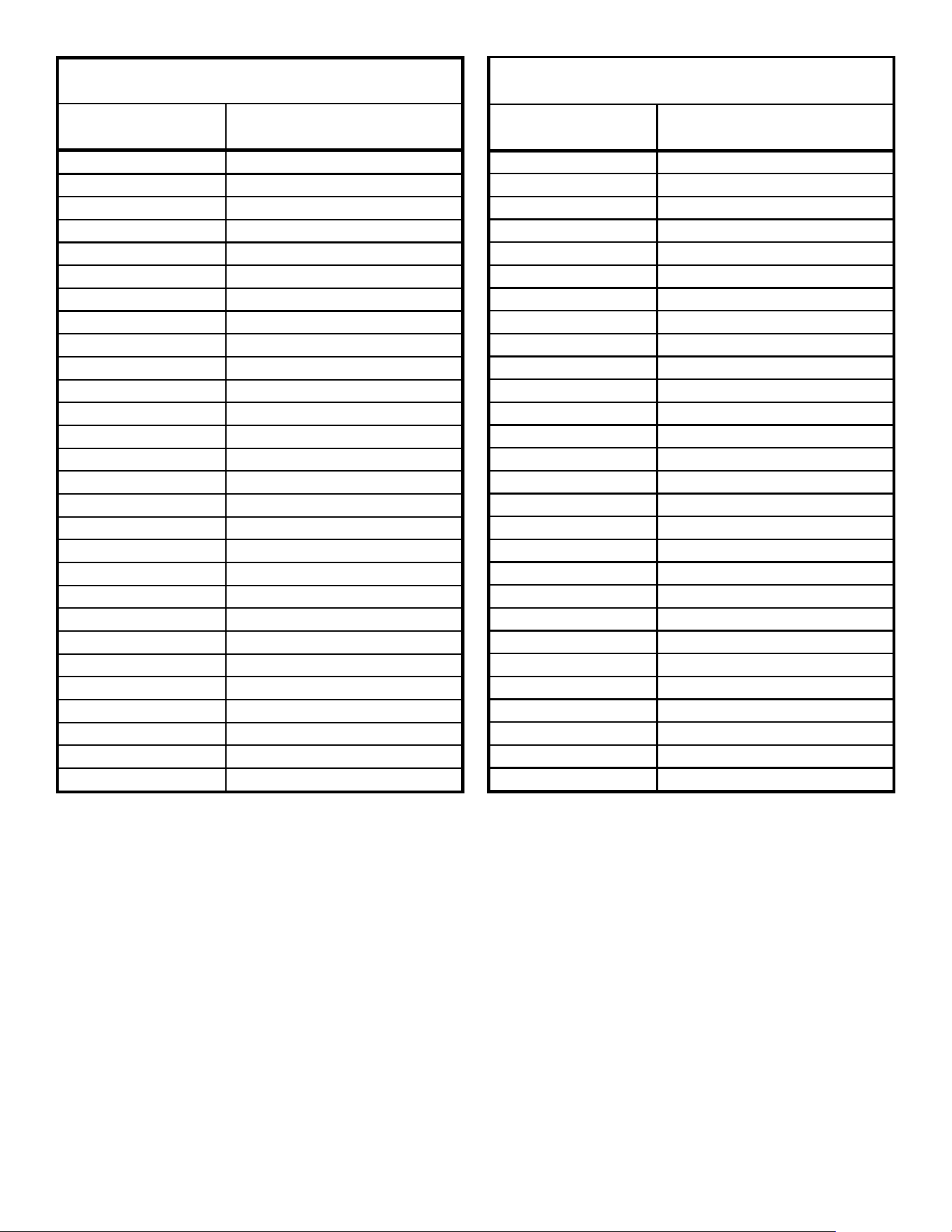
9
SUCTION PRESSURE
SATURATED SUCTION
TEMPERATURE ºF
PSIG R-410A
50 1
52 3
54 4
56 6
58 7
60 8
62 10
64 11
66 13
68 14
70 15
72 16
74 17
76 19
78 20
80 21
85 24
90 26
95 29
100 31
110 36
120 41
130 45
140 49
150 53
160 56
170 60
SATURATED SUCTION PRESSURE
TEMPERATURE CHART
LIQUID PRESSURE
SATURATED LIQUID
TEMPERATURE ºF
PSIG R-410A
200 70
210 73
220 76
225 78
235 80
245 83
255 85
265 88
275 90
285 92
295 95
305 97
325 101
355 108
375 112
405 118
415 119
425 121
435 123
445 125
475 130
500 134
525 138
550 142
575 145
600 149
625 152
SATURATED LIQUID PRESSURE
TEMPERATURE CHART
NOTE: Specifications And Performance Data Listed Herein Are Subject To Change Without Notice.
10
EXPANSION VALVE SYSTEM
NOTE: Units matched with indoor coils equipped
with a TXV should be charged by Subcooling only.
SUBCOOLING FORMULA = SATURATED LIQUID LINE
TEMPERATURE - LIQUID LINE TEMPERATURE
1. Purge gauge lines. Connect service gauge manifold
to base-valve service ports. Run system at least 10
minutes to allow pressure to stabilize.
2. Clamp a pipe clamp thermometer on the liquid line
near the liquid line service valve and 4-6" from the
compressor on the suction line.
a. Ensure the thermometer makes adequate contact
to obtain the best possible readings.
b. The temperature read with the thermometer
should be lower than the saturated condensing
temperature.
3. The dierence between the measured saturated
condensing temperature and the liquid line
temperature is the liquid Subcooling value.
4. TXV-based systems should have a Subcooling value
of 8°F +/- 1°F.
5. Add refrigerant to increase Subcooling and remove
refrigerant to decrease Subcooling.
NOTE: Units matched with indoor coils equipped
with a TXV should be charged by Subcooling only.
Superheat can also be utilized to best verify
charge levels with an adjustable TXV and make
adjustments when needed in unique applications
due to refrigerant line length, differences in
height between the indoor and outdoor unit and
refrigerant tubing sizes. These adjustments
should only be performed by qualified service
personnel.
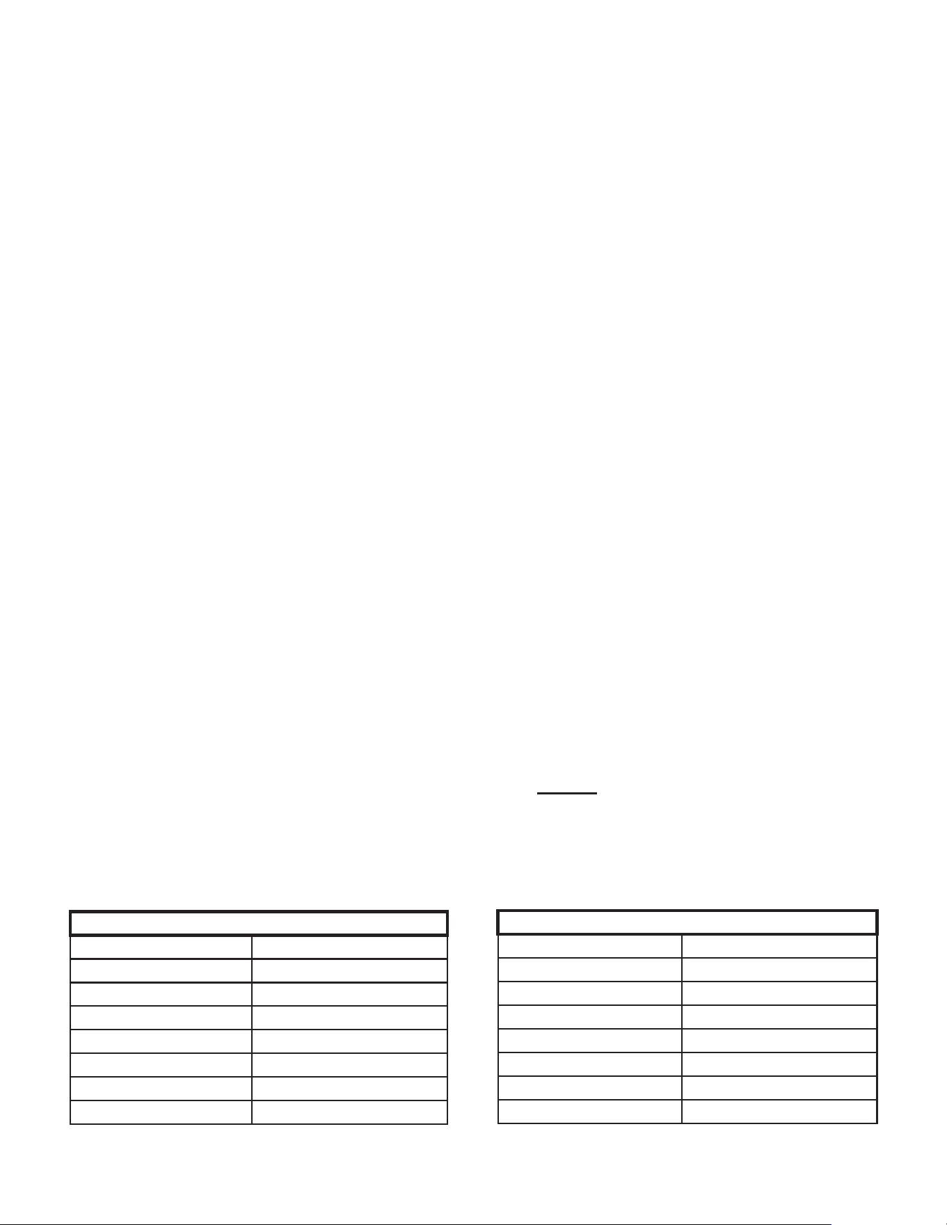
Superheat Settings for Expansion Valve System
Tonnage SH at Compressor
1.5 14°F +/- 1°F
2 11°F +/- 1°F
2.5 9°F +/- 1°F
3 9°F +/- 1°F
3.5 9°F +/- 1°F
4 9°F +/- 1°F
5 9°F +/- 1°F
Superheat settings for TXV systems for GSXH5,
ASXH3, ASXH5, GSXB4, ASXH4 and GSXM4 family.
ADVANCED ADJUSTMENT
RECOMMENDATIONS
NOTE: Units matched with indoor coils equipped
with a TXV should be charged by Subcooling only.
SUPERHEAT FORMULA = SUCTION LINE
TEMPERATURE - SATURATED SUCTION
TEMPERATURE
1. Clamp a pipe clamp thermometer near the suction line
4-6” from the compressor on the suction line.
a. Ensure the thermometer makes adequate contact
for the best possible readings.
b. The temperature read with the thermometer
should be higher than the saturated suction
temperature.
2. The dierence between the measured saturated
suction temperature and the suction line temperature
is the Superheat value.
3. TXV-based systems should have a Superheat value
as shown in the table below.
4. Adjust Superheat by turning the TXV valve stem
clockwise to increase and counterclockwise to
decrease.
a. If Subcooling and Superheat are low, adjust the
TXV to the superheat setting specied in the table
below and then check Subcooling.
b. If Subcooling is low and Superheat is high, add
charge to raise Subcooling to 8°F +/- 1°F then
check Superheat.
c. If Subcooling and Superheat are high, adjust the
TXV valve to the superheat specied in the table
below then check the Subcooling value.
d. If Subcooling is high and Superheat is low, adjust
the TXV valve to the superheat specied in the
table below and remove charge to lower the
Subcooling to 8°F +/- 1°F.
NOTE: DO NOT adjust the charge based exclusively
on suction pressure unless for general charging
in the case of a gross undercharge.
NOTE: Check the Schrader ports for leaks and
tighten valve cores if necessary. Install caps
finger-tight
Superheat Settings for Expansion Valve System
Tonnage SH at Compressor
1.5 12°F +/- 1°F
2 12°F +/- 1°F
2.5 9°F +/- 1°F
3 9°F +/- 1°F
3.5 9°F +/- 1°F
4 9°F +/- 1°F
5 9°F +/- 1°F
Superheat settings for TXV systems for GSXN4,
ASXN4, GSXN3, ASXN3, VSXN and VSXN4 family.
11
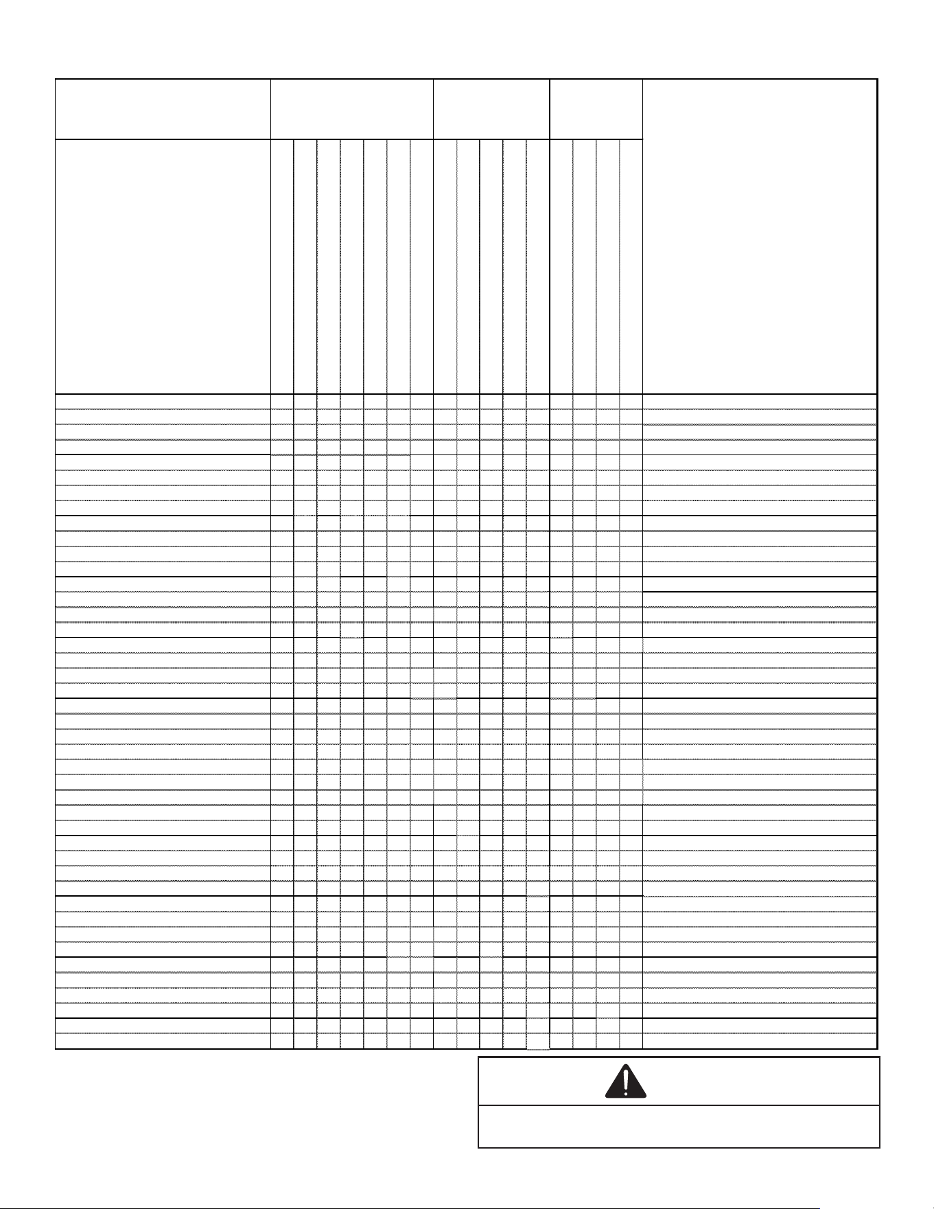
TROUBLESHOOTING INFORMATION
Complaint
Unsatisfactory
Cooling
POSSIBLE CAUSE
DOTS IN ANALYSIS
GUIDE INDICATE
"POSSIBLE CAUSE"
SYMPTOM
System will not start
Compressor will not start - fan runs
Compressor and Condenser Fan will not start
Evaporator fan will not start
Condenser fan will not start
Compressor runs - goes off on overload
Compressor cycles on overload
System runs continuously - little cooling
Too cool and then too warm
Not cool enough on warm days
Certain areas to cool others to warm
Compressor is noisy
Low suction pressure
Low head pressure
High suction pressure
High head pressure
Test Method
Remedy
Power Failure • Test Voltage
Blown Fuse
•
•
• Impact Fuse Size & Type
Loose Connection
• • • • Inspect Connection - Tighten
Shorted or Broken Wires
• •
• • • • Test Circuits with Ohmmeter
Open Overload
• • Test Continuity of Overloads
Faulty Thermostat
•
•
• • Test Continuity of Thermostat and Wiring
Faulty Transformer
•
• Check Control Circuit with Voltmeter
Shorted or Open Capacitor • • •
• Test Capacitor
Internal Compressor Overload Open
• Test Continuity of Overload
Shorted or Grounded Compressor •
• Test Motor Windings
Compressor Stuck •
•
Use Test Cord
Faulty Compressor Contactor •
• • • Test Continuity of Coil and Contacts
Faulty Fan Relay • Test Continuity of Coil and Contacts
Open Control Circuit Test Control Circuit with Voltmeter
Low Voltage • • •
Test Voltage
Faulty Evaporator Fan Motor
•
• Repair or Replace
Shorted or Grounded Fan Motor
• •
• Test Motor Windings
Improper Cooling Anticipator • Check Resistance of Anticipator
Shortage or Refrigerant • • • • Test For Leaks, Add Refrigerant
Restricted Liquid Line •
• • • Replace Restricted Part
Undersized Liquid Line • • • Replace Line
Undersized Suction Line • Replace Line
Not Enough Air across Indoor Coil • • • • Speed Blower, Check Duct Static Pressure
Too Much Air across Indoor Coil • Reduce Blower Speed
Overcharge of Refrigerant • •
· • • Recover Part of Charge
Noncondensibles • • • Recover Charge, Evacuate, Recharge
Recirculation of Condensing Air • •
• Remove Obstruction to Air Flow
Infiltration of Outdoor Air • • •
Check Windows, Doors, Vent Fans, Etc.
Improperly Located Thermostat
•
Relocate Thermostat
Air Flow Unbalanced • • Readjust Air Volume Dampers
System Undersized
• • Refigure Cooling Load
Broken Internal Parts
• Replace Compressor
Broken Valves • Test Compressor Efficiency
Inefficient Compressor • •
• Test Compressor Efficiency
High Pressure Control Open • Reset and Test Control
Unbalanced Power, 3PH • •
• Test Voltage
Wrong Type Expansion Valve • • • Replace Valve
Expansion Valve Restricted
• • • • • • Replace Valve
Oversized Expansion Valve
• • Replace Valve
Undersized Expansion Valve • • • • • Replace Valve
Expansion Valve Bulb Loose • • Tighten Bulb Bracket
Inoperative Expansion Valve • • •
Check Valve Operation
Loose Hold-down Bolts • Tighten Bolts
No Cooling
S yste m
Operating
P re ssu re s
For detailed service information, refer to the
Remote Condensing Unit Service manual.
NOTICE
Units with rotary or reciprocating compressors and non-
bleed TXV’s require a Hard Start Kit.
12
SPLIT SYSTEMS
AIR CONDITIONING AND HEAT PUMP homeowner’s Routine Maintenance Recommendations
We strongly recommend a bi-annual maintenance checkup be performed
before the heating and cooling seasons begin by a qualied servicer.
Replace or Clean Filter
IMPORTANT NOTE: Never operate unit without a
filter installed as dust and lint will build up on
internal parts resulting in loss of efficiency,
equipment damage and possible fire.
An indoor air lter must be used with your comfort system.
A properly maintained lter will keep the indoor coil of
your comfort system clean. A dirty coil could cause poor
operation and/or severe equipment damage.
Your air lter or lters could be located in your furnace, in a
blower unit, or in “lter grilles” in your ceiling or walls. The
installer of your air conditioner or heat pump can tell you
where your lter(s) are, and how to clean or replace them.
Check your lter(s) at least once a month. When they are
dirty, replace or clean as required. Disposable type lters
should be replaced. Reusable type lters may be cleaned.
You may want to ask your dealer about high eciency
lters. High eciency lters are available in both electronic
and non-electronic types. These lters can do a better job
of catching small airborne particles.
Compressor
The compressor motor is hermetically sealed and does not
require additional oiling.
Motors
Indoor and outdoor fan motors are permanently lubricated
and do not require additional oiling.
Clean Outside Coil (Qualified Servicer Only)
WARNING
HIGH VOLTAGE!
Disconnect ALL power before servicing or
installing this unit. Multiple power sources may
be present. Failure to do so may cause property
damage, personal injury or death.
Air must be able to ow through the outdoor unit of your
comfort system. Do not construct a fence near the unit or
build a deck or patio over the unit without rst discussing
your plans with your dealer or other qualied servicer.
Restricted airow could lead to poor operation and/or
severe equipment damage.
Likewise, it is important to keep the outdoor coil clean.
Dirt, leaves, or debris could also restrict the airow. If
cleaning of the outdoor coil becomes necessary, hire
a qualied servicer. Inexperienced people could easily
puncture the tubing in the coil. Even a small hole in the
tubing could eventually cause a large loss of refrigerant.
Loss of refrigerant can cause poor operation and/or severe
equipment damage.
Do not use a condensing unit cover to “protect” the outdoor
unit during the winter, unless you rst discuss it with your
dealer. Any cover used must include “breathable” fabric to
avoid moisture buildup.
BEFORE CALLING YOUR SERVICER
• Check the thermostat to conrm that it is properly set.
• Wait 15 minutes. Some devices in the outdoor unit or
in programmable thermostats will prevent compressor
operation for awhile, and then reset automatically.
Also, some power companies will install devices
which shut o air conditioners for several minutes on
hot days. If you wait several minutes, the unit may
begin operation on its own.
CAUTION
To avoid the risk of equipment damage or fire, install the
same amperage breaker or fuse as you are replacing. If the
circuit breaker or fuse should open again within thirty days,
contact a qualified servicer to correct the problem.
If you repeatedly reset the breaker or replace
the fuse without having the problem corrected, you run the
risk of severe equipment damage.
• Check the electrical panel for tripped circuit breakers
or failed fuses. Reset the circuit breakers or replace
fuses as necessary.
• Check the disconnect switch near the indoor furnace
or blower to conrm that it is closed.
• Check for obstructions on the outdoor unit. Conrm
that it has not been covered on the sides or the top.
Remove any obstruction that can be safely removed.
If the unit is covered with dirt or debris, call a qualied
servicer to clean it.
• Check for blockage of the indoor air inlets and outlets.
Conrm that they are open and have not been
blocked by objects (rugs, curtains or furniture).
• Check the lter. If it is dirty, clean or replace it.
• Listen for any unusual noise(s), other than normal
operating noise, that might be coming from the
outdoor unit. If you hear unusual noise(s) coming from
the unit, call a qualied servicer.
13
START-UP CHECKLIST
Condenser / Heat Pump (including all Inverter)
ELECTRICAL (Outdoor Unit)
Line Voltage (Measure L1 and L2 Voltage) L1 - L2
Secondary Voltage (Measure Transformer Output Voltage) NOT ALL MODELS R - C
Compressor Amps
Condenser Fan Amps
TEMPERATURES (Indoor Unit)
Return Air Temperature (Dry bulb / Wet bulb) DB °F WB °F
DB °F WB °F
Delta T (Difference between Supply and Return Temperatures) DB °F
PRESSURES / TEMPERATURES (Outdoor Unit)
Suction Circuit (Pressure / Suction Line Temperature) PSIG TEMP °F
Liquid Circuit (Pressure / Liquid Temperature) PSIG TEMP °F
Outdoor Air Temperature (Dry bulb / Wet bulb) DB °F WB °F
SUPERHEAT / SUBCOOLING SH SC
Line set length in Feet
Additional Refrigerant Charge Added over Factory Charge (Ounces)
Additional Checks
Check wire routings for any rubbing
Check factory wiring and wire connections.
Check product for proper clearances as noted by installtion instructions
°F to °C formula: (°F - 32) divided by 1.8 = °C °C to °F formula: (°C multiplied by 1.8) + 32 = °F
Model Number
Serial Number
Cooling Supply Air Temperature (Dry bulb / Wet bulb)

14
THIS PAGE IS LEFT INTENTIONALLY BLANK.

15
THIS PAGE IS LEFT INTENTIONALLY BLANK.
16
CUSTOMER FEEDBACK
We are very interested in all product comments.
Please ll out the feedback form on one of the following links:
Goodman
®
Brand Products: (http://www.goodmanmfg.com/about/contact-us).
Amana
®
Brand Products: (http://www.amana-hac.com/about-us/contact-us).
You can also scan the QR code on the right for the product brand
you purchased to be directed to the feedback page.
GOODMAN
®
BRAND
AMANA
®
BRAND
GOODMAN
®
BRAND
AMANA
®
BRAND
PRODUCT REGISTRATION
Thank you for your recent purchase. Though not required to get the protection of
the standard warranty, registering your product is a relatively short process, and
entitles you to additional warranty protection, except that failure by California and
Quebec residents to register their product does not diminish their warranty rights.
The duraon of warranty coverages in Texas diers in some cases.
For Product Registration, please register as follows:
Goodman
®
Brand products: (https://www.goodmanmfg.com/product-registration).
Amana
®
Brand products: (http://www.amana-hac.com/product-registration).
You can also scan the QR code on the right for the product brand
you purchased to be directed to the Product Registration page.
NOTE: Specifications and performance data listed herein are subject to change without notice.
Quality Makes the Dierence!
All of our systems are designed and manufactured with the same high quality standards regardless of size or eciency.
We have designed these units to signicantly reduce the most frequent causes of product failure. They are simple to
service and forgiving to operate. We use quality materials and components. Finally, every unit is run tested before it
leaves the factory. That’s why we know. . .There’s No Better Quality.
Visit our website at www.goodmanmfg.com or www.amana-hac.com for information on:
• Products • Customer Services • Contractor Program and Training
• Warranties • Parts • Financing Options
19001 Kermier Rd. Waller, TX 77484
www.goodmanmfg.com -or- www.amana-hac.com
© 2021-2022 Daikin Comfort Technologies Manufacturing, L.P.
is a registered trademark of Maytag Corporation or its related companies and is used under license. All rights reserved.