Recommended
Find the latest version of this and other Honeywell documents on our website: https://buildings.honeywell.com/security.
Copy Right
© 2022 Honeywell International Inc. All rights reserved. No part of this publication may be reproduced by any means without
written permission from Honeywell. The information in this publication is believed to be accurate in all respects. However,
Honeywell cannot assume responsibility for any consequences resulting from the use thereof. The information contained
herein is subject to change without notice. Revisions or new editions to this publication may be issued to incorporate such
changes. For patent information, see https://buildings.honeywell.com/us/en/support/legal/patents.
Revision
Issue
Date
Revisions
A
0
3/2022
New document.
B
0
5/2022
Add
wiper camera
i
Honeywell 35 Series IP Cameras User Guide
Cautions and Warnings
Warning:
To ensure compliance with electrical safety standards, Local
Certified / CSA Certified / UL Listed LPS or Class 2 power
adapters are required. Power over Ethernet (PoE) shall be
provided by listed Information Technology Equipment meeting
the IEEE 802.3at PoE standard. The PoE is not intended to be
connected to exposed (outside plant) networks.
Consult Honeywell for the recommended adapter.
Caution
:
Invisible LED radiation (850 nm). Avoid exposure to beam.
Regulatory Statements
Photobiological safety
This product fulfills the requirements for photobiological safety according to IEC/ EN
62471 (risk group 1).
General Data Protection Regulation
Please be aware that this product can store personal data. Personal data is protected by
the General Data Protection Regulation (2016/679) in Europe and therefore the owners
of personal data have obtained certain rights thanks to this regulation.

ii
Honeywell 35 Series IP Cameras User Guide
We strongly advise you to be fully aware of these owner (“data subjects”) rights as well as
which limitations you have to obey regarding the use and distribution of this data.
Further details can be found on the GDPR website of the EU
FCC Compliance Statement
Information to the User: This equipment has been tested and found to comply with the
limits for a Class A digital device, pursuant to part 15 of the FCC Rules. These limits are
designed to provide reasonable protection against harmful interference in a residential
installation.
This equipment generates, uses, and can radiate radio frequency energy and, if not
installed and used in accordance with the instructions, may cause harmful interference
to radio communications. However, there is no guarantee that interference will not
occur in a particular installation. If this equipment does cause harmful interference to
radio or television reception, which can be determined by turning the equipment off and
on, the user is encouraged to try to correct the interference by one or more of the
following measures:
• Reorient or relocate the receiving antenna.
• Increase the separation between the equipment and receiver.
• Connect the equipment into an outlet on a circuit different from that to which the
receiver is connected.
• Consult the dealer or an experienced radio/TV technician for help. Changes or
modifications not expressly approved by the party responsible for compliance could
void the user's authority to operate the equipment. This Class A digital apparatus
complies with Canadian ICES-003.
Note:
Changes or modifications not expressly approved by the party responsible for
compliance could void the user’s authority to operate the equipment.
Manufacturer’s Declaration of Conformance
North America
The equipment supplied with this guide conforms to UL 62368-1 and CSA C22.2 No.
62368-1 (except for HC35WZ5R30W).
Europe
The manufacturer declares that the equipment supplied with this guide is compliant
with the European Parliament and Council Directive on the Restrictions of the use of
certain hazardous substances in electrical and electronic equipment (2011/65/EU) as

iii
Honeywell 35 Series IP Cameras User Guide
Amended by RoHS 3 (2015/863), and the essential requirements of the EMC Directive
(2014/30/EU), conforming to the requirements of standards EN 55032 for emissions,
EN 50130-4 for immunity, and EN 62368 for electrical equipment safety.
Waste Electrical and Electronic Equipment (WEEE)
Correct Disposal of this Product (applicable in the European Union and other
European countries with separate collection systems).
This product should be disposed of, at the end of its useful life, as per applicable
local laws, regulations, and procedures.
Check Local Waste Guidelines
Components of this product require separate waste collection. Check local waste
guidelines for sorting rules.
Safety Instructions
Before installing or operating the unit, read and follow all instructions. After
installation, retain the safety and operating instructions for future reference.
1. HEED WARNINGS - Adhere to all warnings on the unit and in the operating
instructions.
2. INSTALLATION
• Install in accordance with the manufacturer’s instructions.
• Installation and servicing should be performed only by qualified and experienced
technicians to conform to all local codes and to maintain your warranty.
• Any wall or ceiling mounting of the product should follow the manufacturer’s
instructions and use a mounting kit approved or recommended by the manufacturer.
• It is not allowed to install the PTZ camera upside down.
3. POWER SOURCES - This product should be operated only from the type of power
source indicated on the marking label. If you are not sure of the type of power
supplied to your facility, consult your product dealer or local power company.
4. MOUNTING SYSTEM - Use only with a mounting system recommended by the
manufacturer or sold with the product.
5. ATTACHMENTS/ACCESSORIES - Do not use attachments/accessories not
recommended by the product manufacturer as they may result in the risk of fire,
electric shock, or injury to persons.

iv
Honeywell 35 Series IP Cameras User Guide
6. CLEANING - Do not use liquid cleaners or aerosol cleaners. Use a damp cloth for
cleaning.
7. SERVICING - Do not attempt to service this unit yourself. Refer all servicing to
qualified service personnel.
8. REPLACEMENT PARTS - When replacement parts are required, be sure the service
technician has used replacement parts specified by the manufacturer or have the
same characteristics as the original part. Unauthorized substitutions may result in
fire, electric shock or other hazards. Using replacement parts or accessories other
than the original manufacturers may invalidate the warranty.
Warranty and Service
Subject to the terms and conditions listed on the product warranty, during the warranty
period Honeywell will repair or replace, at its sole option, free of charge, any defective
products returned prepaid.
In the event you have a problem with any Honeywell product, please call Customer
Service at 1.800.323.4576 for assistance or to request a Return Merchandise
Authorization (RMA) number.
Be sure to have the model number, serial number, and the nature of the problem
available for the technical service representative.
Prior authorization must be obtained for all returns, exchanges, or credits. Items
shipped to Honeywell without a clearly identified Return Merchandise Authorization
(RMA) number may be refused.

I
TABLE OF CONTENTS
1 Introduction ...................................................................................... 1
Overview ...................................................................................................................................... 1
Supported Browsers ............................................................................................................... 1
Key Features .............................................................................................................................. 2
2 Accessing the Camera ................................................................. 4
Installing the Unified Tool .................................................................................................... 4
Discovering Your Camera on the Network ..................................................................... 6
Initializing Cameras................................................................................................................ 7
Assigning a New IP Address to Your Camera ................................................................ 8
Configure IP Address Setting ....................................................................................... 9
Configure DNS Server Address.................................................................................... 9
Upgrading the Camera’s Firmware ................................................................................... 9
Accessing the Camera from a Web Browser ............................................................... 10
3 Logging in & Viewing Live Video ........................................... 11
Logging in to the Camera via the Web Client ............................................................ 11
Before You Begin ............................................................................................................ 11
Logging in to the Camera ........................................................................................... 11
Using the Main Page ........................................................................................................... 13
System Menu ................................................................................................................... 14
Stream Profile .................................................................................................................. 14
Camera Name .................................................................................................................. 15
Live View Toolbar ........................................................................................................... 15
VA Event List .................................................................................................................... 15
Language .......................................................................................................................... 16
Administrator Account ................................................................................................. 16
4 Configuring Camera Settings ......................................... 17
Configuring General Settings .......................................................................................... 17
Configuring Video Settings .............................................................................................. 17
Mode ................................................................................................................................... 17

II
Honeywell 35 Series IP Cameras User Guide
Video Stream .................................................................................................................... 18
ROI ....................................................................................................................................... 20
Configuring Audio Settings .............................................................................................. 21
Configuring Image Settings ............................................................................................. 21
Image Adjustment ......................................................................................................... 22
Scene Mode ...................................................................................................................... 22
Exposure ............................................................................................................................ 23
White Balance (WB) Setting ....................................................................................... 23
DayNight Setting ............................................................................................................ 23
Noise Reduction ............................................................................................................. 24
Enhance Image ............................................................................................................... 24
Configuring OSD .................................................................................................................. 25
Configuring Privacy Mask ................................................................................................. 25
5 Configuring Network Settings ........................................ 27
Configuring Network General Settings ........................................................................ 27
Configuring Streaming Protocols .................................................................................. 28
Configuring SMTP Settings .............................................................................................. 31
Configuring SNMP Settings ............................................................................................. 32
Configuring QoS Settings ................................................................................................. 33
Configuring HTTPS Settings ............................................................................................ 34
HTTPS ................................................................................................................................. 34
Upload Files ..................................................................................................................... 34
Configuring IEEE 802.1x Settings ................................................................................. 35
6 Configuring Video Analytics ............................................ 37
Motion Detection .................................................................................................................. 37
Smart Motion Detection .................................................................................................... 38
Tampering Detection .......................................................................................................... 39
Intrusion Detection .............................................................................................................. 40
Multi Loitering ....................................................................................................................... 41
People Counter ...................................................................................................................... 42
7 Configure Alarm and Event .............................................. 44
Configuring Alarm In and Alarm Out ............................................................................ 44
Alarm Input ....................................................................................................................... 45
Alarm Output ................................................................................................................... 45
Configuring SD Card Alarm .............................................................................................. 46
8 Configure Storage Settings .............................................. 47
SD Card Management ........................................................................................................ 47
SD Card Status ................................................................................................................ 48

III
Honeywell 35 Series IP Cameras User Guide
SD Card Format .............................................................................................................. 48
Content Management ........................................................................................................ 49
Searching and Viewing the Records ....................................................................... 49
Search Results ................................................................................................................ 49
Recording Settings............................................................................................................... 50
9 Configure System Settings ............................................... 52
Configuring System General Settings .......................................................................... 52
Configuring Maintenance Settings ............................................................................... 53
Upgrading Firmware ..................................................................................................... 53
Rebooting the Camera ................................................................................................. 54
Restoring the Camera .................................................................................................. 54
Importing/Exporting Files.......................................................................................... 54
Configuring User Accounts Settings ............................................................................ 56
Account Management ................................................................................................. 57
Configuring Access List Settings ................................................................................... 57
10 Configuring PTZ Settings .................................................. 59
Preset ........................................................................................................................................ 59
Scan Management ............................................................................................................... 60
Patrol ......................................................................................................................................... 61
Recording Patrol ................................................................................................................... 62
Idle Action ................................................................................................................................ 63
Power Up Action .................................................................................................................... 63
11 Viewing System Information ............................................ 65
Log .............................................................................................................................................. 65
Operation Log ................................................................................................................. 65
Alarm Log .......................................................................................................................... 65
Collect Log ........................................................................................................................ 66
Version ...................................................................................................................................... 66
12 Trouble Shooting ..................................................................... 67
Troubleshooting for Common Issues ........................................................................... 67
13 Appendix ........................................................................................ 68
List of Symbols ...................................................................................................................... 68

IV
Honeywell 35 Series IP Cameras User Guide
Figures
Figure 1 Install Unified Tool................................................................................................................................................................................ 5
Figure 2 Select Installation Folder .................................................................................................................................................................. 5
Figure 3 Confirm Installation ............................................................................................................................................................................. 6
Figure 4 Splash Screen ......................................................................................................................................................................................... 6
Figure 5 Scanning the Network ........................................................................................................................................................................ 7
Figure 6 Device List ................................................................................................................................................................................................. 7
Figure 7 Initialize Page 1 ...................................................................................................................................................................................... 8
Figure 8 Initialize Page 2 ...................................................................................................................................................................................... 8
Figure 9 IP Assignment ......................................................................................................................................................................................... 9
Figure 10 Firmware Upgrade 1 ...................................................................................................................................................................... 10
Figure 11 Firmware Upgrade 2 ...................................................................................................................................................................... 10
Figure 12 Main Page ........................................................................................................................................................................................... 13
Figure 13 PTZ Panel ............................................................................................................................................................................................. 14
Figure 14 Live View Toolbar ............................................................................................................................................................................. 15
Figure 15 General Settings .............................................................................................................................................................................. 17
Figure 16 Mode Tab ............................................................................................................................................................................................. 18
Figure 17 Video Stream ...................................................................................................................................................................................... 18
Figure 18 ROI Settings ....................................................................................................................................................................................... 20
Figure 19 Audio Settings ................................................................................................................................................................................... 21
Figure 20 Image Settings .................................................................................................................................................................................. 22
Figure 21 Privacy Mask ...................................................................................................................................................................................... 26
Figure 22 Network General Settings ........................................................................................................................................................... 27
Figure 23 Streaming Protocols-HTTP ........................................................................................................................................................ 28
Figure 24 Streaming Protocols-RTSP ........................................................................................................................................................ 29
Figure 25 SMTP Settings .................................................................................................................................................................................. 31
Figure 26 HTTPS Settings ................................................................................................................................................................................ 34
Figure 27 IEEE 802.1x Configurations – EAP-TLS .............................................................................................................................. 36
Figure 28 Motion Detection ............................................................................................................................................................................. 37
Figure 29 Smart Motion ..................................................................................................................................................................................... 38
Figure 30 Tampering Detection ..................................................................................................................................................................... 39
Figure 31 Intrusion Detection ........................................................................................................................................................................ 40
Figure 32 Multi Loitering .................................................................................................................................................................................. 41
Figure 33 People Counter ................................................................................................................................................................................. 42
Figure 34 Alarm In and Alarm Out ................................................................................................................................................................ 44
Figure 35 No SD Card ......................................................................................................................................................................................... 48
Figure 36 SD Card Onboard ............................................................................................................................................................................ 48
Figure 37 System General Settings ............................................................................................................................................................. 52
Figure 38 Preset Settings.................................................................................................................................................................................. 59
Figure 39 Scan Settings..................................................................................................................................................................................... 60
Figure 40 Patrol Settings .................................................................................................................................................................................. 61
Figure 41 Recording Patrol .............................................................................................................................................................................. 62
Figure 42 Idle Action ............................................................................................................................................................................................ 63
Figure 43 Power Up Action ............................................................................................................................................................................... 64

V
Honeywell 35 Series IP Cameras User Guide
Tables
Table 1 Live View Toolbar Icons ..................................................................................................................................................................... 15
Table 2 Cameras Resolution ............................................................................................................................................................................ 19
Table 3 Cameras Frame Rate .......................................................................................................................................................................... 19
Table 4 Compatible SD Card ........................................................................................................................................................................... 47
Table 5 Troubleshooting for Common Issues ........................................................................................................................................ 67
Table 6 List of Symbols ...................................................................................................................................................................................... 68

CHAPTER
1
Honeywell 35 Series IP Cameras User Guide
1 INTRODUCTION
This document provides instructions for accessing, configuring, and operating the
Honeywell 35 Series cameras. This document is intended for system installers,
administrators, and operators.
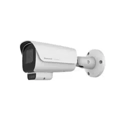
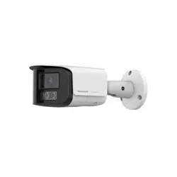
Overview
Honeywell 35 Series IP cameras integrate traditional camera and network video
technology, combining video data collection and transmission. These flexible, fully
featured cameras are the ideal choice for a wide range of surveillance applications.
The cameras offer 2 megapixel resolution at up to 60 frames per second and 8
megapixel resolution at up to 30 frames per second and use video compression
technology to save bandwidth and storage while ensuring maximum video quality. All
the cameras are True Day/Night with intelligent IR capability, providing illumination in
low-light and nighttime scenes up to 60m for IPC models and 150m for PTZ models.
Also, all the cameras support WDR function at up to 120 DB. Each camera comes with
configurable motion detection and camera tamper detection and supports up to 5 user-
defined privacy mask areas. In addition to a 12V DC adapter for IPC models and 24V AC
for PTZ models, all the IPC cameras support Power over Ethernet (PoE) and PTZ
cameras support POE+, eliminating the need for a separate power supply and
associated wiring. All models also support local video storage on two micro SDHC cards
(up to 512 GB) when network service is interrupted.
Supported Browsers
Note:
35 Series cameras support Windows desktop system and don’t support mobile system.
Chrome and Edge browsers are supported:

2
Honeywell 35 Series IP Cameras User Guide
Browser
Version
Chrome
91.0.4472.164 (Official Build) (64
-bit)
Edge
92.0.902.7 (Official Build) (64
-bit)
Key Features
The key features in Honeywell Series 35 IP camera are:
Camera
• Up to 8MP (3840 x 2160) cameras
• Video parameter setup, such as electronic shutter and gain
• Video Analytics: Motion Detection, Smart Motion, Tampering, Intrusion, Multi
Loitering, People Counter
• True WDR (120 dB)
• True day/night mode using a removable IR cut filter
• Low-light with 2D/3D noise reduction saving storage and bandwidth together with
smart codec
• For use as part of Video Systems which comply with NDAA
Storage
• Central server backup
• Series 35 camera has one SD card slot, files stored on SD card
Network
• Up to 10 connections
• Compatible with the following network protocols: IPv4, IPv6, TCP/IP, HTTP, HTTPS,
RTSP/RTP/RTCP, IGMP/Multicast, SMTP, DHCP, NTP, DNS, QoS, SNMP, 802.1X,
UDP, ICMP, ARP, TLS
• Support the following security modes: User account and password protection, HTTPS,
IP Filter, Digest authentication, TLS1.2 only, Stream encryption, AES128 / 256, SSH /
Telnet closed, PCI-DSS compliance
• Support the following languages: Arabic, Czech, Dutch, English, French, German,
Italian, Japanese, Korean, Polish, Portuguese (Brazil), Russian, Spanish, Turkish
• Camera configuration and management via Ethernet
Events and Analytics
• Support the following Video Analytics types: Motion Detection, Smart Motion,
Tampering, Intrusion, Multi Loitering, People Counter.
• Support the following event types: Video motion detection, Alarm input, Recording

3
Honeywell 35 Series IP Cameras User Guide
notification, Tampering
• Support the following event linkage mode: Event notification using digital output,
Email and MicroSD card.
User Management
• Each user belongs to specific group
• Different user rights for each group
System Management
• Log function
• Support controlling access permission by verifying the client PC’s IP address

CHAPTER
4
Honeywell 35 Series IP Cameras User Guide
2 ACCESSING THE CAMERA
This chapter contains the following sections:
• Installing the Unified Tool, page 4
• Discovering Your Camera on the Network, page 4
• Initializing Cameras, page 7
• Assigning a New IP Address to Your Camera, page 8
• Upgrading the Camera’s Firmware, page 9
• Accessing the Camera from a Web Browser, page 10
Installing the Unified Tool
To get the installation package of Unified Tool:
Visit https://myhoneywellbuildingsuniversity.com/ and login. Navigate to Download
Center, search and download the installation package of Unified Tool to your computer.
You need to unzip the package.
To install the Unified Tool:
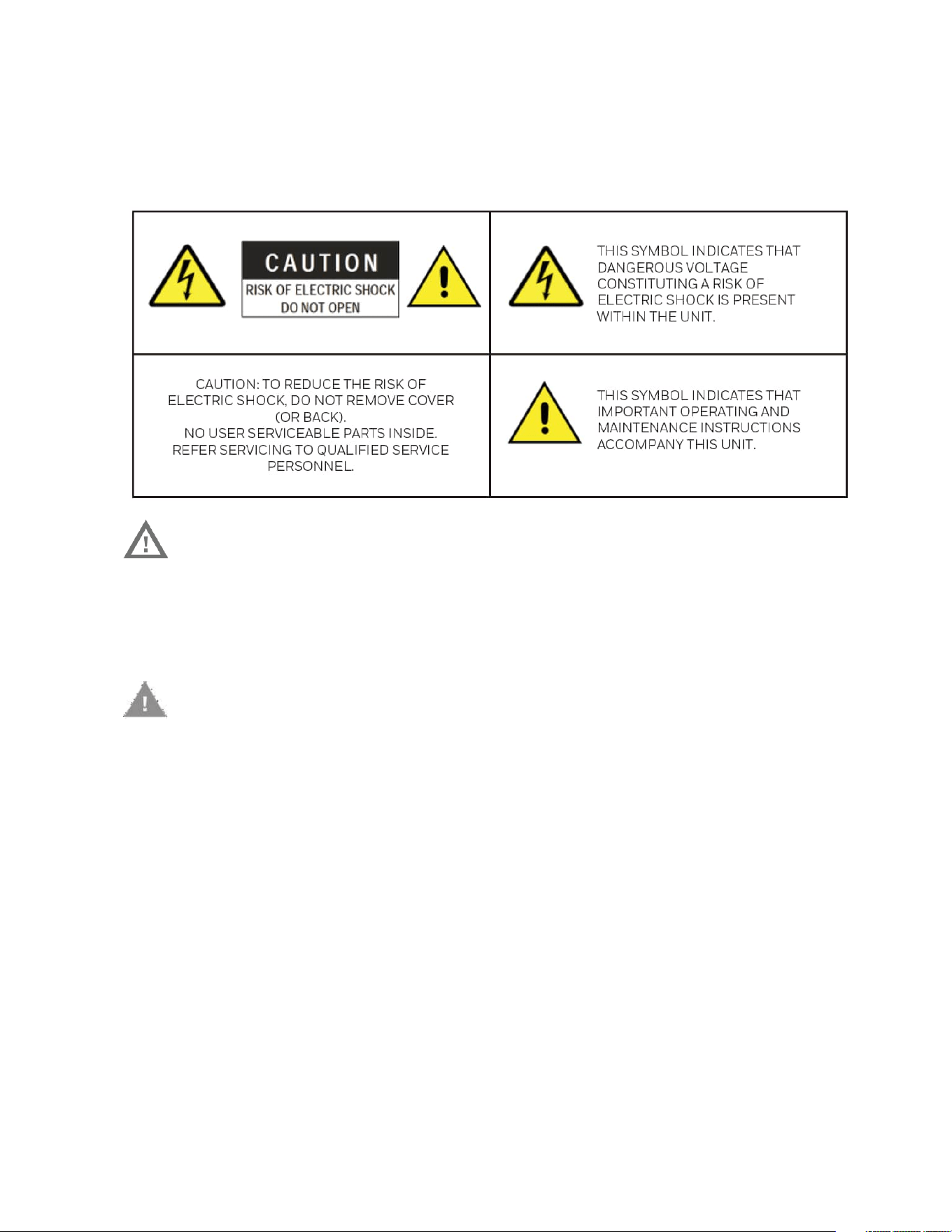
1. Double-click the installation program in the installation package.
5
Honeywell 35 Series IP Cameras User Guide
Figure 1 Install Unified Tool
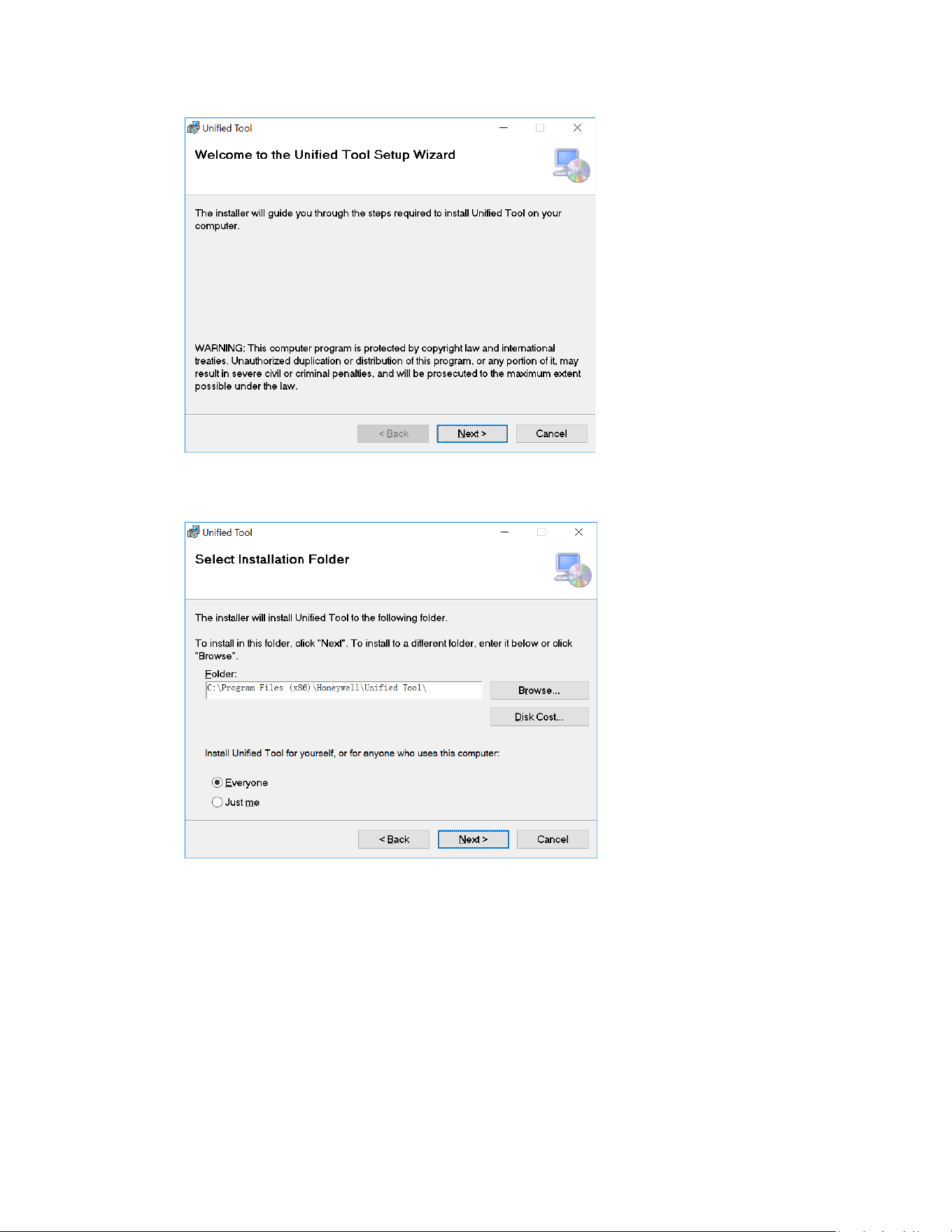
2. Click Next and the following figure is displayed:
Figure 2 Select Installation Folder
3. Follow the on-screen instructions to configure your settings and click Next. The
following figure is displayed:
6
Honeywell 35 Series IP Cameras User Guide
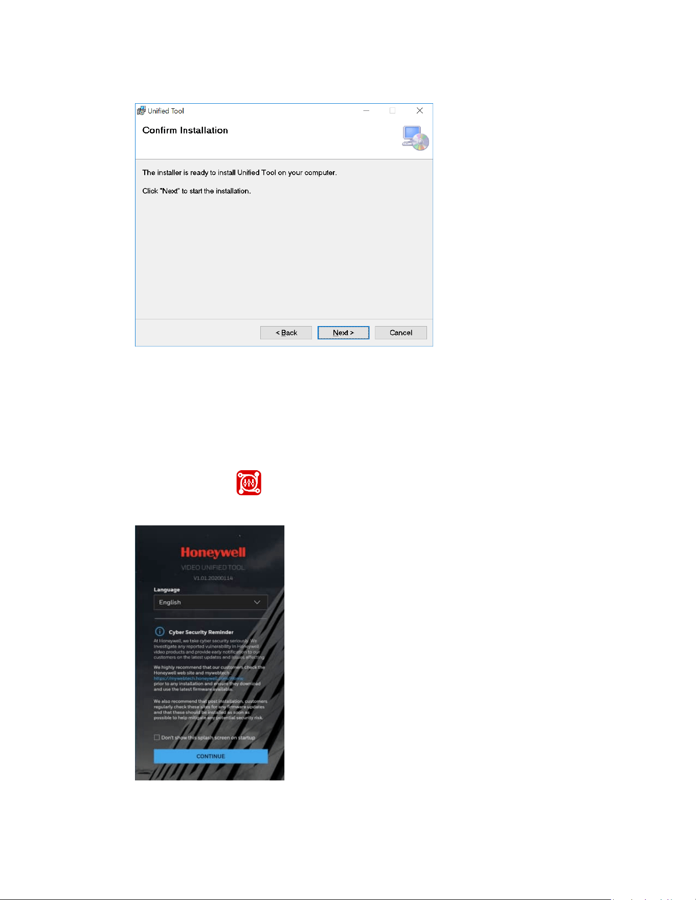
Figure 3 Confirm Installation
4. Click Next. When the installation is completed, click Close. A shortcut of Unified
Tool will be displayed on your desktop.
Discovering Your Camera on the Network
1. Double-click on the desktop and the following figure is displayed:
Figure 4 Splash Screen
2. Select your language from the dropdown list of Language. Currently, only English
is supported.
7
Honeywell 35 Series IP Cameras User Guide
3. Check “Don’t show the splash window on startup” and this page can be skipped
next time.
If you want to check the splash window again, click as shown in Figure 5 and
select the checkbox of Show the splash page on startup.
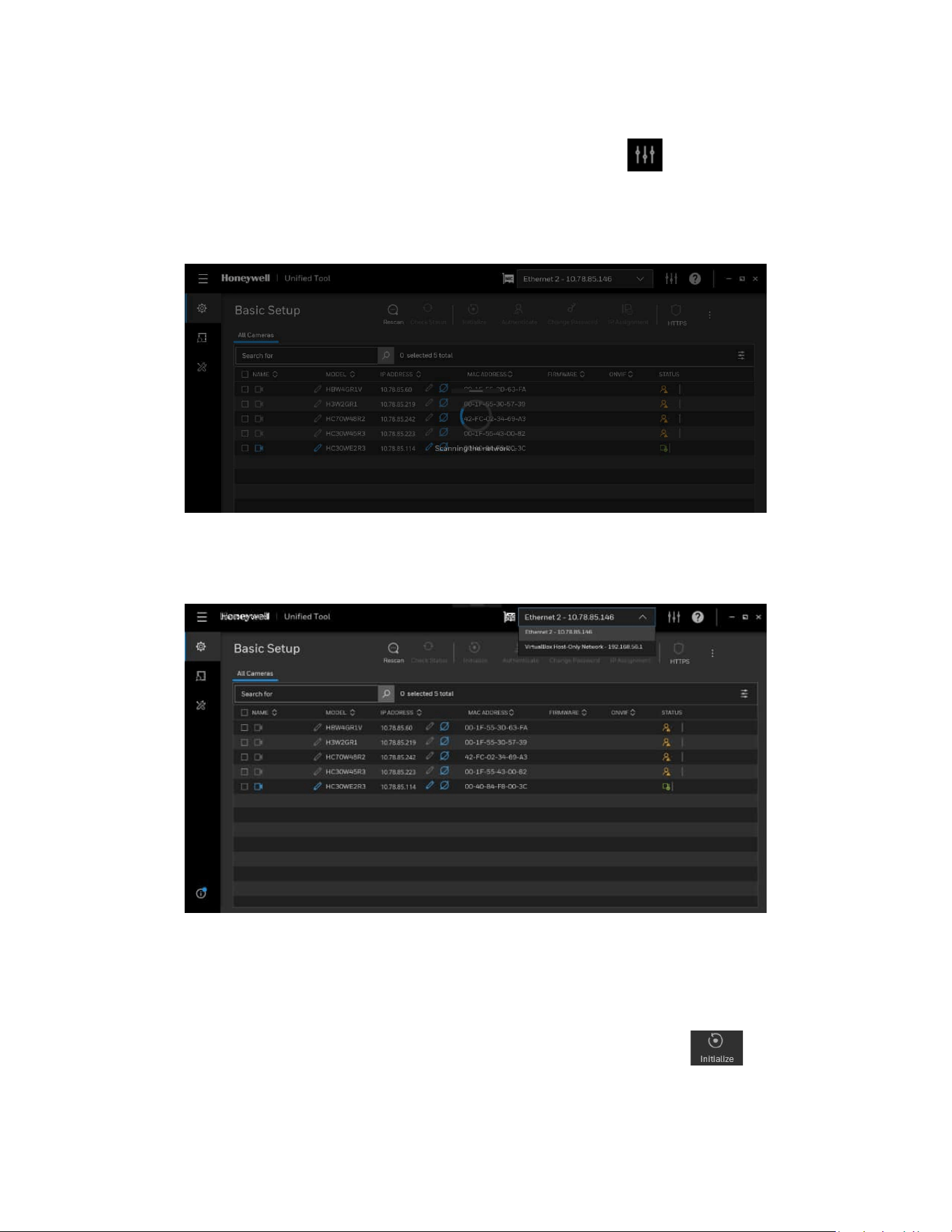
4. Click CONTINUE. It will scan devices in the network automatically.
Figure 5 Scanning the Network
After the scanning, all scanned devices in the same subnet and different subnet will be
displayed in the devices list.
Figure 6 Device List
Initializing Cameras
It is recommended to initialize the 35 series cameras by clicking . By initialization,
you can set the camera password in batch.
8
Honeywell 35 Series IP Cameras User Guide
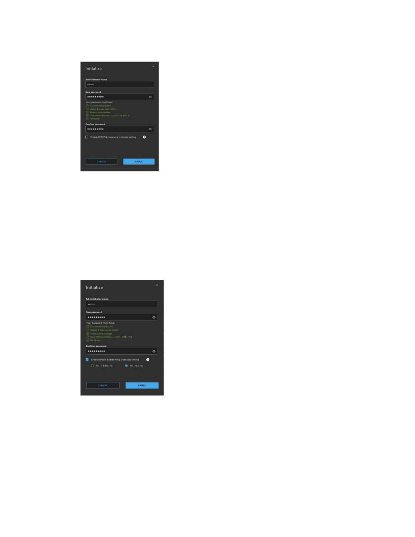
Figure 7 Initialize Page 1
On the Initialize page, set Administrator name and New password. Select the checkbox
to enable ONVIF & streaming protocols setting. Select HTTPS only. Click APPLY.
Note:
•
Honeywell strictly recommends to use HTTPs only and Honeywell will
not hold responsible for the consequences.
•
ONVIF & streaming protocols setting only supports 35 & 70 series
camera. Unsupported model will be skipped.
Figure 8 Initialize Page 2
After initializing successfully, you can authenticate the camera and configure other
setting.
Assigning a New IP Address to Your Camera
The current IP address of your camera appears in the IP ADDRESS column of the
devices list. If you want, you can assign a new static IP address to the camera.
9
Honeywell 35 Series IP Cameras User Guide
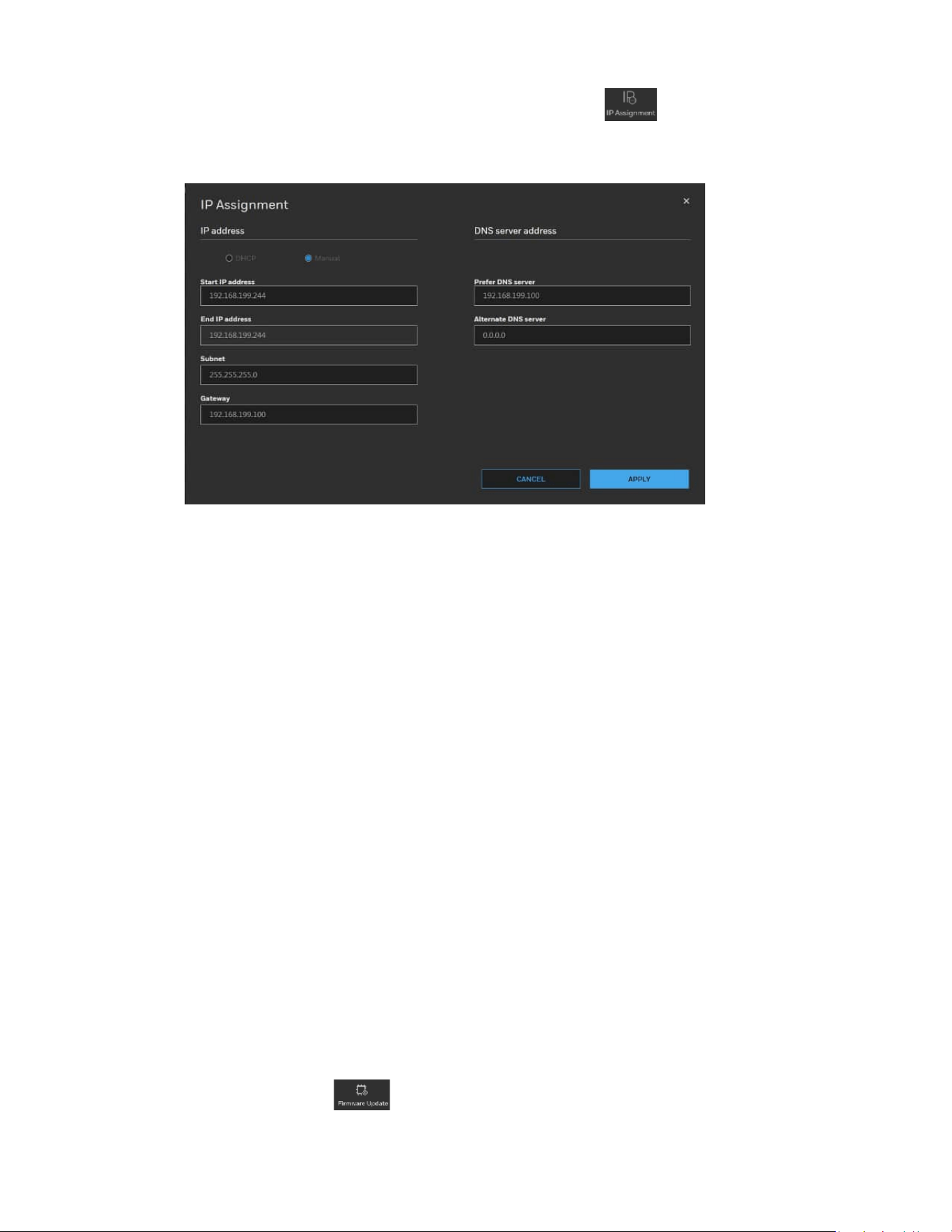
Select the target device(s) as shown in Figure 5, click and the following figure is
displayed:
Figure 9 IP Assignment
Configure IP Address Setting
• To obtain IP address, subnet mask, and default gateway settings automatically,
select the check box of DHCP.
• To configure IP address, subnet mask, and default gateway settings manually, select
the check box of Manual and enter the settings. If you enter the start IP address, the
system can calculate the end IP address automatically according to the number of
your selected device(s).
• After all settings are completed, click APPLY.
Configure DNS Server Address
Configure the DNS server address and click APPLY.
Upgrading the Camera’s Firmware
Before you begin using your camera, make sure you have the latest firmware installed.
You can upgrade a single camera or multiple cameras at the same time.
Select the Maintenance tab from the left pane as shown in Figure 5, select target
device(s) and click and the following window is displayed:
10
Honeywell 35 Series IP Cameras User Guide
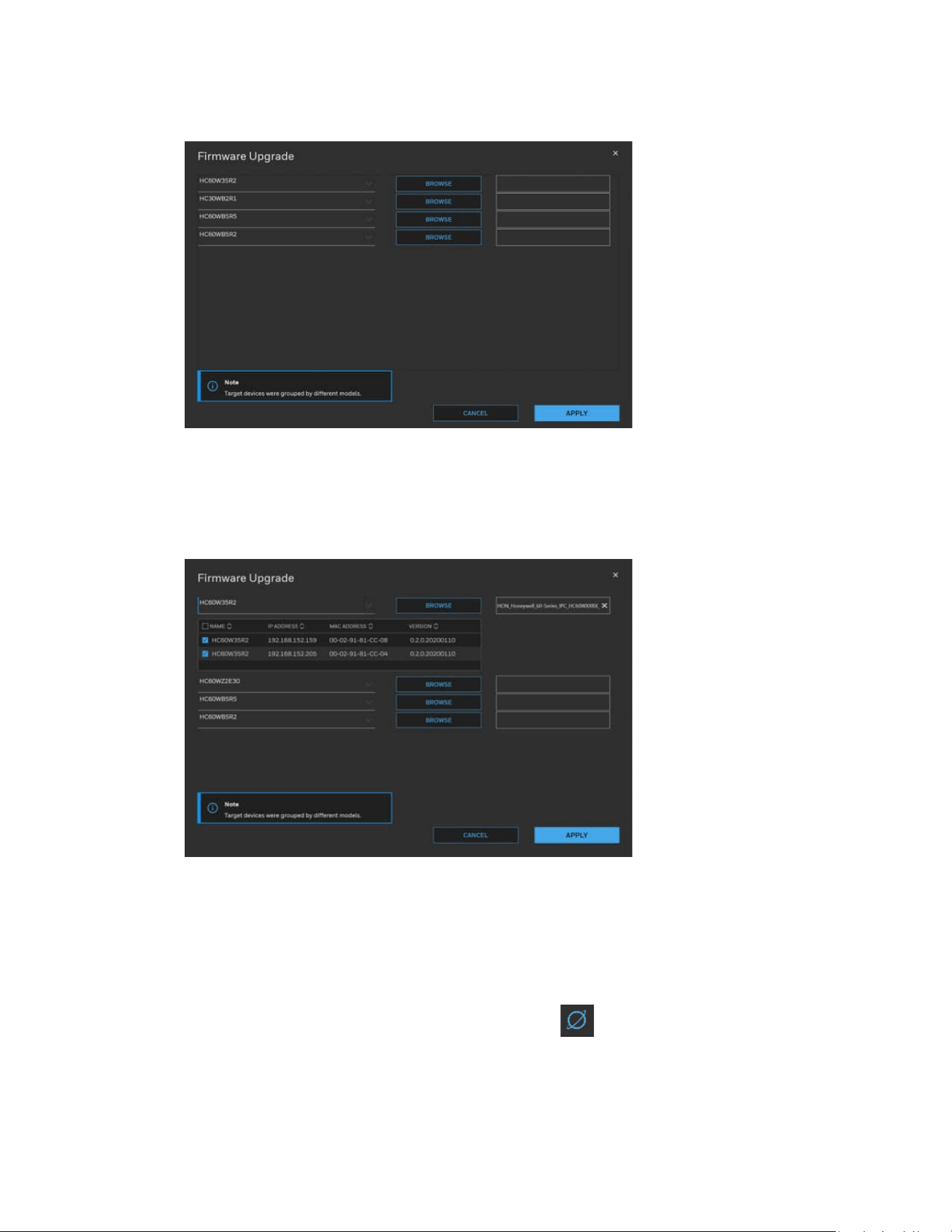
Figure 10 Firmware Upgrade 1
The devices were grouped by model. To upgrade the firmware:
1. Select the target device(s) under a model.
2. Click BROWSE and select the upgrade file from your computer.
Figure 11 Firmware Upgrade 2
3. Click APPLY. You can check the progress status in the device list.
Accessing the Camera from a Web Browser
To access the camera from a web browser, click next to the IP address of the device
as shown in Figure 6.

CHAPTER
11
Honeywell 35 Series IP Cameras User Guide
3 LOGGING IN & VIEWING LIVE VIDEO
This chapter contains the following sections:
• Logging in to the Camera via the Web Client, page 11
• Using the Main Page, page 13
Logging in to the Camera via the Web Client
Using the web client, you can monitor live video, play back recorded video, and configure
camera settings.
Before You Begin
Before you log in to the web client, ensure that the following conditions are met:
• The camera is properly connected to the network.
• The camera’s IP address and the PC’s IP address are in the same network segment. If
there is a router, set the corresponding gateway and subnet mask.
• A network connection has been established. To check this, ping the camera’s IP
address. (Enter "ping [IP address]").
Note:
The new security enhancements do not allow pinging the camera IP address.
Logging in to the Camera
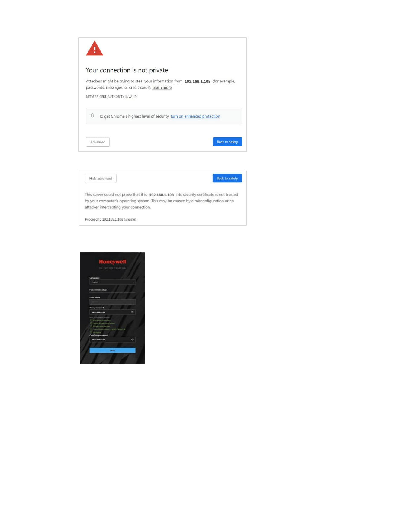
1. Open Google Chrome, type the camera’s IP address in the address bar, and then
click Enter. For example, if your camera’s IP address is 192.168.1.108, you would
type https://192.168.1.108.
2. The following window is displayed. Click Advanced.
12
Honeywell 35 Series IP Cameras User Guide
3. The following window is displayed. Click Proceed to 192.168.1.108 (unsafe).
4. For security purposes, you are required to create a new secure password at the
first login.
The password must be at least 8 characters in length and contain at least one
uppercase letter, one lowercase letter, one number, and one special character (-
_!@%^.~?#$=+*:,&). The password cannot be blank. Click SAVE.
5. The login screen is displayed. Enter the admin user name and password, and then
click LOGIN.
13
Honeywell 35 Series IP Cameras User Guide
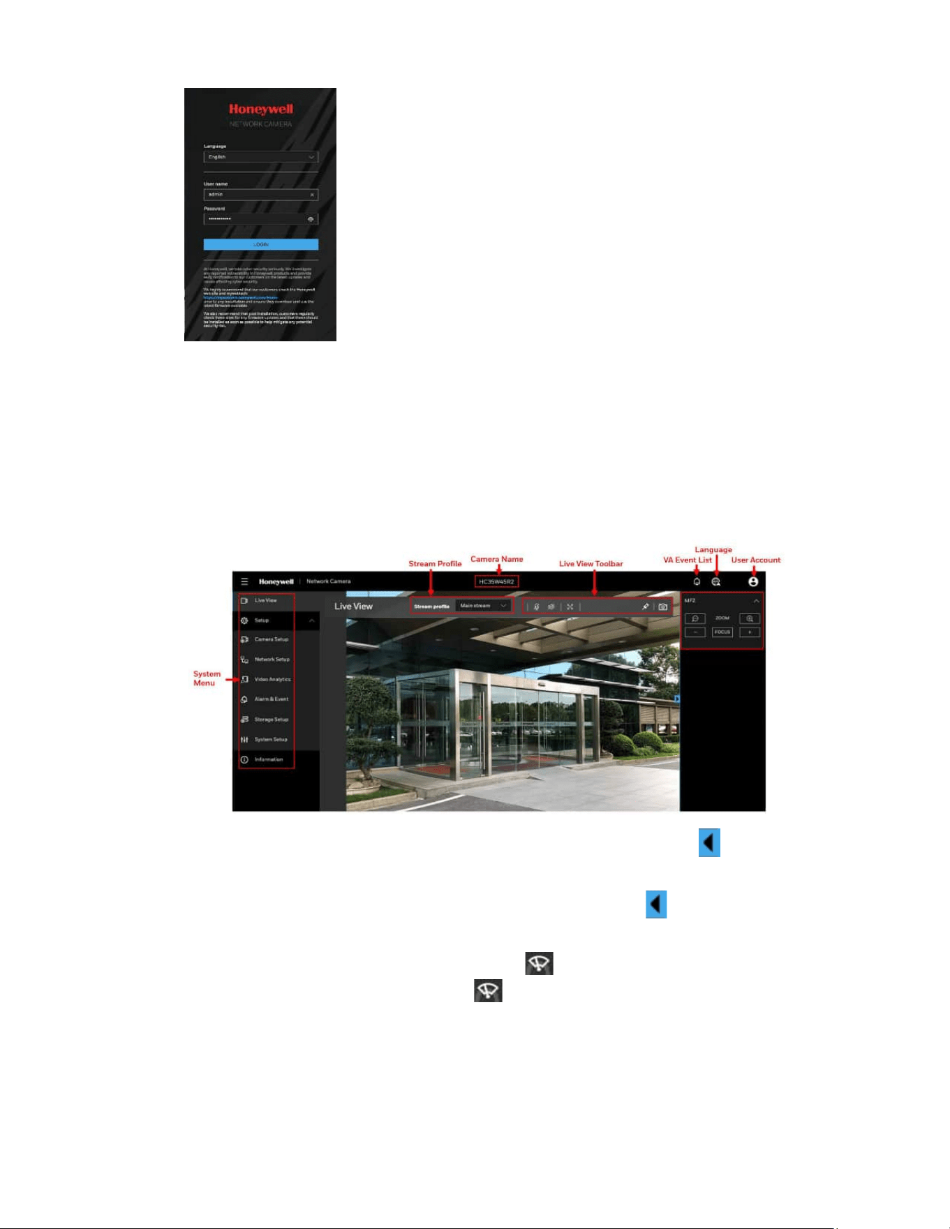
Using the Main Page
The main page includes the following areas: system menu, live view toolbar, VA event
list, language selection and user account settings.
Figure 12 Main Page
• For MFZ IPC model, an MFZ panel can be accessed by clicking on the right as
shown in Figure 12.
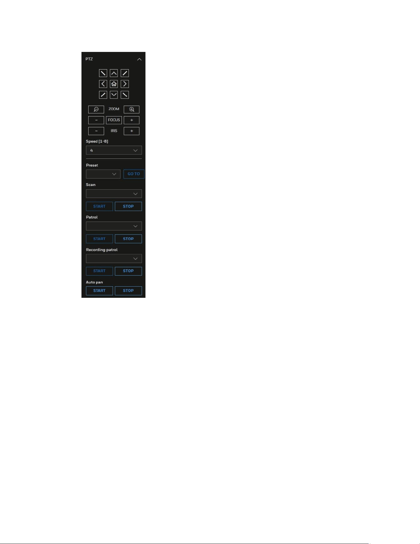
• For PTZ model, a PTZ panel can be accessed by clicking on the right as shown in
Figure 13.
• For HC35WZ5R30W model, you can use in the Live View Toolbar to control the
camera wiper. Each time you click , the camera wiper swipes once.
14
Honeywell 35 Series IP Cameras User Guide
Figure 13 PTZ Panel
For details on PTZ operation, see Configuring PTZ Settings on page 59.
System Menu
When you log in to the camera by using the web client, the main page opens by default.
To access the setup page or information page, select the corresponding tab.
Stream Profile
To set the stream profile, in the Stream profile list, select Main stream, Sub stream, or
Third stream.
Main stream: Delivers high definition video for real-time monitoring, recording, and
storage. Uses the most bandwidth.
Sub stream: Delivers high-definition video for real-time monitoring, recording, and
storage. Uses the most bandwidth.
15
Honeywell 35 Series IP Cameras User Guide
Third stream: Delivers low-definition video.
The properties for each stream type are configured on the Setup > Camera Setup >
Video page (see Configuring Video Settings on page 17).
Camera Name
You can change the camera name according to your needs. For more information, see
Configuring System General Settings on page 52.
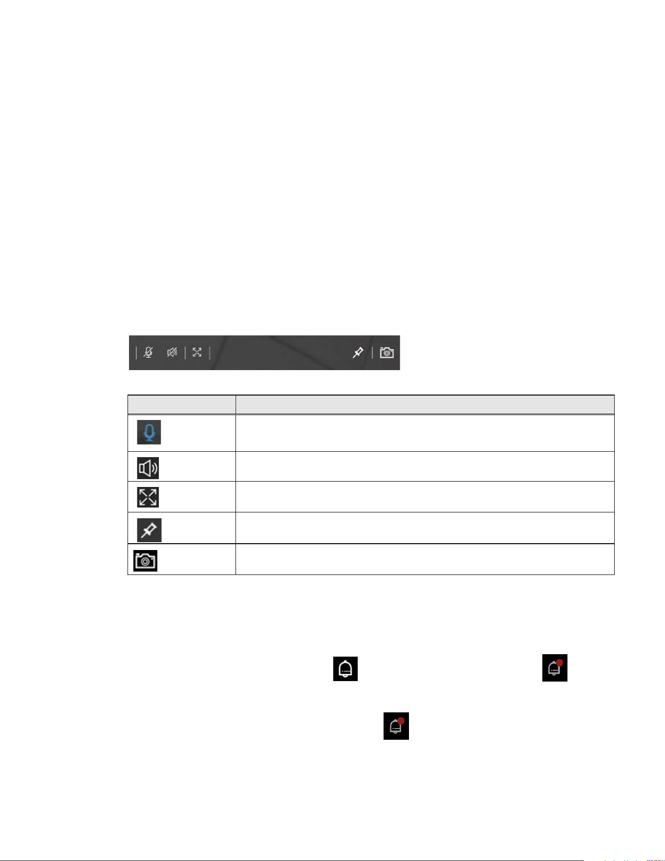
Live View Toolbar
The Live View toolbar allows you to take snapshot. The following table lists the controls
in more detail.
Figure 14 Live View Toolbar
Table 1 Live View Toolbar Icons
Icon
Description
By default this option is enabled. You can talk and audience can listen through in built camera
speakers, Click to disable this option.
Click to turn on the audio to listen to the monitoring site. Click it again to turn off the audio.
Click to switch to the full screen mode.
Click to Pin the live view to the toolbar. Click once again to unpin.
Click to capture and save video images. The captured images will be displayed in a pop-up
window. Right click the image and select Save picture as to save it in JPEG (*.jpg).
VA Event List
To view the list of VA events, click the icon on the Main Page. The icon will be
blinking when VA alarm comes in.
Note:
Max 100 VA alarms will
be listed after clicking to display event information by
cycling. Please go to
Information
>
Logs
>
Alarm log to see or search more alarm log
records. Refer to Alarm Log.
16
Honeywell 35 Series IP Cameras User Guide
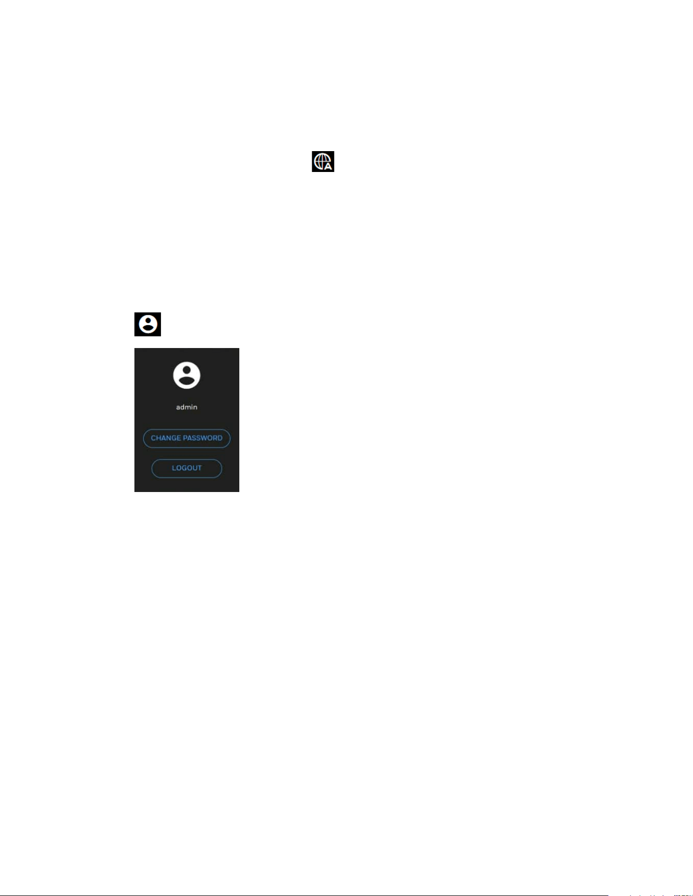
Language
To switch a language, click the icon on the Main Page.
Administrator Account
Note:
The Administrator’s account name and password is set by the user at the first login.
To configure current login user’s password or log out the current user account, click the
icon on the Main Page. The following window is displayed.
Click CHANGE PASSWORD to change the current login user’s password.
Click LOG OUT to log out the current account.
CHAPTER
17
Honeywell 35 Series IP Cameras User Guide
4 CONFIGURING CAMERA
SETTINGS
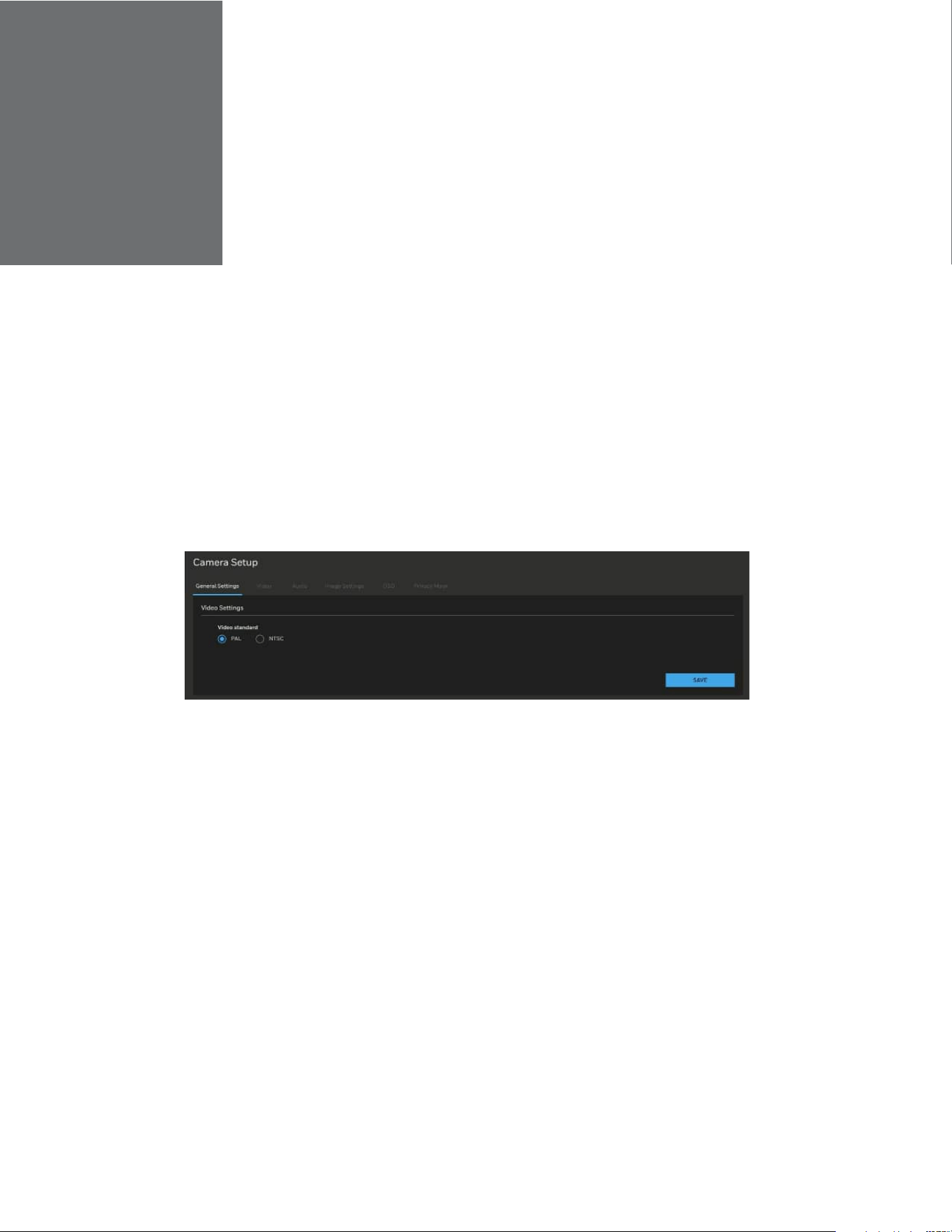
Configuring General Settings
Go to Setup > Camera Setup > General Settings.
On this page, you can configure the general video settings.
To change the video standard, select PAL or NTSC. Click SAVE.
Figure 15 General Settings
Configuring Video Settings
Go to Setup > Camera Setup > Video.
This section describes how to configure Video stream and ROI settings.
Mode
Go to Setup > Camera Setup > Video > MODE.
Note:
•
The Mode function is applicable for HC35WZ2R25.
•
Changing the video mode will clear the following settings: privacy mask,
image setting, motion, preset position and focus window.
18
Honeywell 35 Series IP Cameras User Guide
Figure 16 Mode Tab
2-Megapixel (16:9) (Max 30fps): Select it and the maximum resolution will be
1920x1080.
2-Megapixel (16:9) (Max 60fps): Select it and the maximum resolution will be
1920x1080. It’s non-true WDR mode.
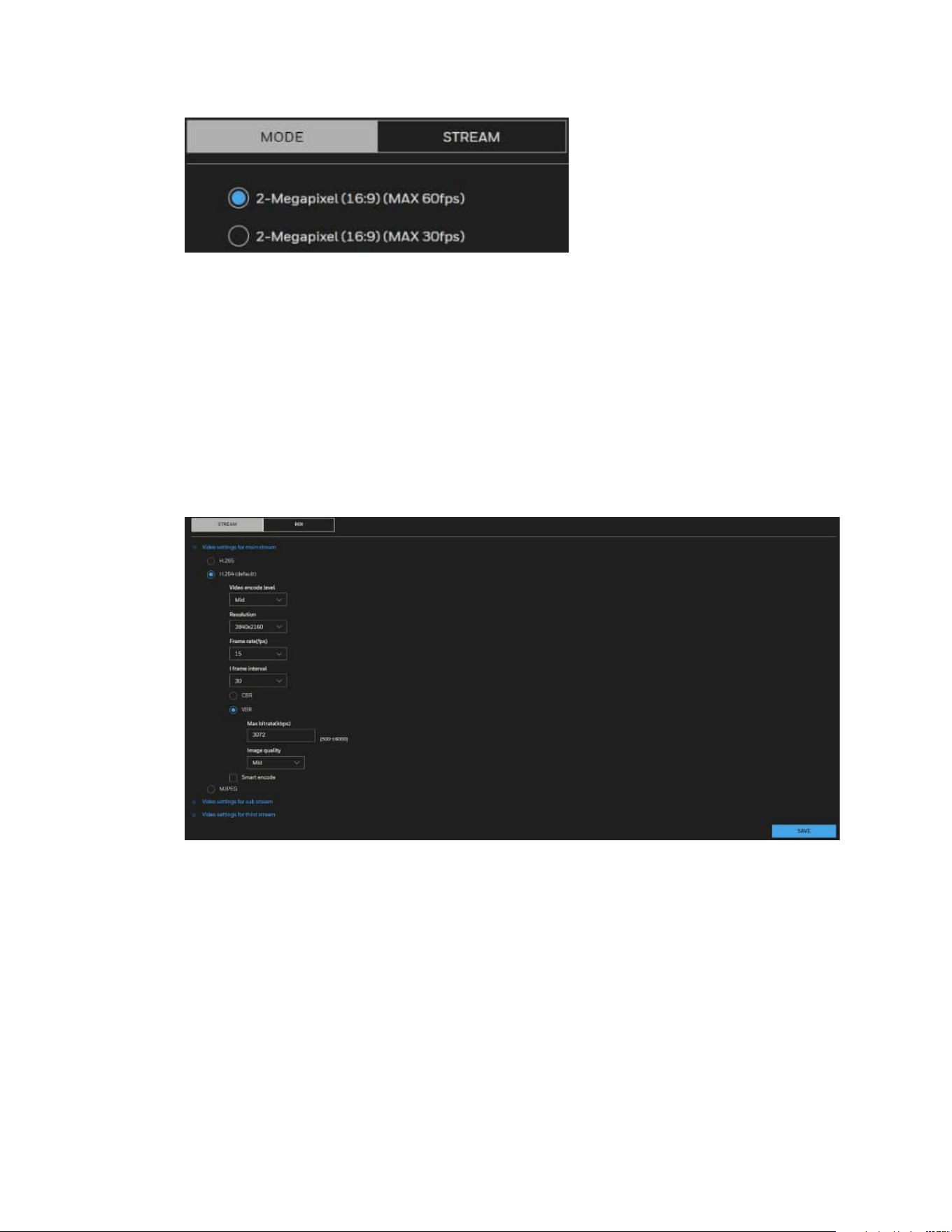
Video Stream
Go to Setup > Camera Setup > Video > STREAM.
Figure 17 Video Stream
Select H.265, H.264(Default), or MJPEG, and apply the video settings for main stream,
sub stream and third stream.
Note:
It is recommended to use camera with no more than 5 fps when MJPEG is applied as it
consumes large bandwidth.
Video encode level: Select a value from the drop-down list box.
Resolution: Select a value from the drop-down list box. A higher resolution means
better image quality.
See the following table for resolution of each model:

19
Honeywell 35 Series IP Cameras User Guide
Table 2 Cameras Resolution
Model
Main
Stream
Sub
Stream
Third
Stream
HC35W43R3
/HC35W43R2
/
HC35WB3R3
/HC35WB3R2
/
HC35WE3R3/HC35WE3R
2
2304x1296/1920x
1080/1280x720
704
x576(PAL)/704x
480(NTSC)
/640
x480/352x288(PAL)/352
x
240(NTSC)
640
x480/352x288(PAL)/
352
x240(NTSC)/320x240
HC35W45R3
/HC35W45R2
/
HC35WB5R3
/HC35WB5R2
/
HC35WE5R3/HC35WE5R
2
/HC35W25R3
2592x1944/2592x
1520/1920x1080/
1280x720
704
x576(PAL)/704x
480(NTSC)
/640
x480/352x288(PAL)/352
x
240(NTSC)
1920x1080
(MAX 12
fps)
/640x480/352x288(P
AL)/352
x240(NTSC)/320x
240
HC35W48R3/HC35W48R2/
HC35WB8R3/HC35WB8R2
/HC35WE8R3/HC35WE8R
2
3840x2160/2592x
1944/2592x1520/
2560x1440/2304x
1296/1920x1080/
1280x720
704
x576(PAL)/704x
480(NTSC)
/640
x480/352x288(PAL)/352
x
240(NTSC)
640
x480/352x288(PAL)/
352
x240(NTSC)/320x240
HC35WZ2R25
1920x1080/1280x
720
704
x576(PAL)/704x
480(NTSC)
/640
x480/352x288(PAL)/352
x
240(NTSC)
640
x480/352x288(PAL)/
352
x240(NTSC)/320x240
HC35WZ5R30
2592x1944/2592x
1520/1920x1080/
1280x720
704
x576(PAL)/704x
480(NTSC)
/640
x480/352x288(PAL)/352
x
240(NTSC)
640
x480/352x288(PAL)/
352
x240(NTSC)/320x240
Frame rate(fps):
This limits the maximum refresh frame rate per second. Set the frame rate higher for
smoother video quality and for recognizing moving objects in the field of view.
If the video standard is set to PAL, the frame rates are selectable from 1-50 fps. If the
video standard is set to NTSC, the frame rates are selectable from 1-60 fps.
The frame rate will decrease if you select a higher resolution.
See the following table for frame rate of each model:
Table 3 Cameras Frame Rate
Main
Stream
Sub
Stream
Third
Stream
MAX 30fps
MAX 15fps for encryption under HTTPS
N
ote: For HC35WZ2R25, refer to the
frame rate below
MAX 30fps (WDR
On)
MAX 60fps (WDR Off)
MAX 15fps for encryption under HTTPS
MAX 30fps
MAX 15fps for encryption under
HTTPS
MAX 30fps (Not available for
encryption)
I-frame interval: Determine within how many frames interval the firmware will plant an I
frame. The shorter the duration, the more likely you will get better video quality, but at
the cost of higher network bandwidth consumption.
CBR: Constant Bit Rate
The bit rate remains constant (recommended for low-bandwidth environments).
Required if MJPEG compression is used.
VBR: Variable Bit Rate
20
Honeywell 35 Series IP Cameras User Guide
The bit rate changes according to the complexity of the scene.
Max bitrate(kbps): Indicates the maximal value of the bit rate. Set 500~12000 for max
bitrate.
Image Quality: Select a desired quality ranging from Lowest to Highest.
Smart encode: Check the checkbox to enable Smart Encode.
• Smart encode includes H.264 & H.265.
• The storage space will be reduced fifty percent when smart encode is enabled.
• Only main stream supports smart encode.
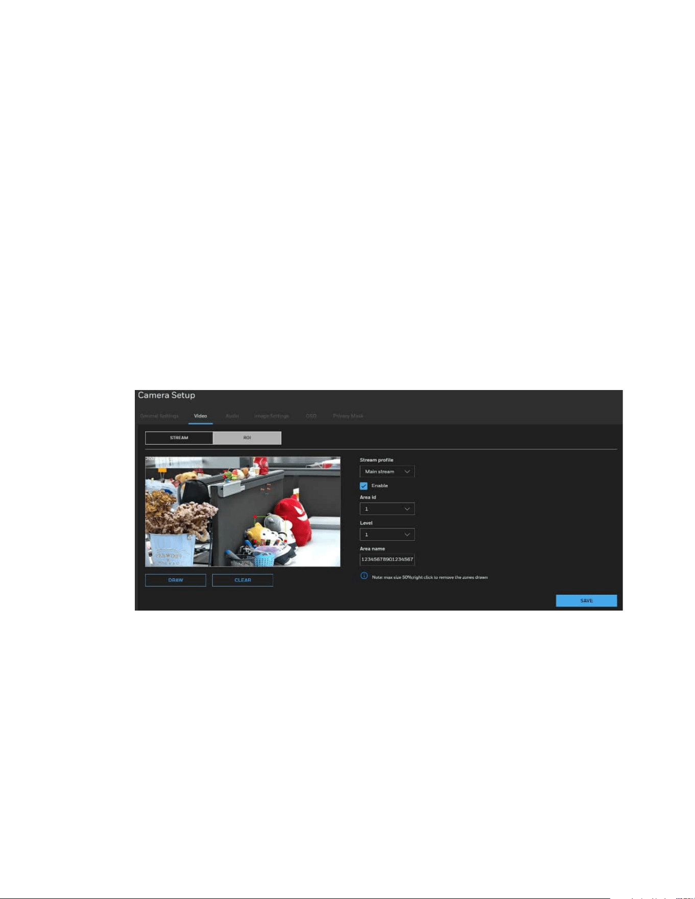
ROI
The ROI function allows you to configure 8 ROI windows (Region of Interest, with
Foreground quality) on the screen. Areas not included in any ROI windows will be
considered as the non-interested areas. The details in the ROI areas will be transmitted
in a higher-quality video format. you may set up an ROI window as a privacy mask by
covering a protected area using an ROI window, while the rest of the screen becomes
the non-interested area.
Go to Setup > Camera Setup > Video > ROI.
Figure 18 ROI Settings
Stream profile: select Main stream, Sub stream, or Third stream to set the stream
profile.
Enable: Check the checkbox to enable the ROI (Region of Interest).
Area id: Select a value from the drop-down list box to set the ROI area ID. You can add 8
areas in total.
Level: Select a value from the drop-down list box to set the visual effect of ROI. Setting
as Level 1 will get the best effect for highest quality video within the interested area and
the fuzziest video for non-interested areas.
Area name: Enter a customized name for areas. The maximum value cannot exceed 32
bytes.
21
Honeywell 35 Series IP Cameras User Guide
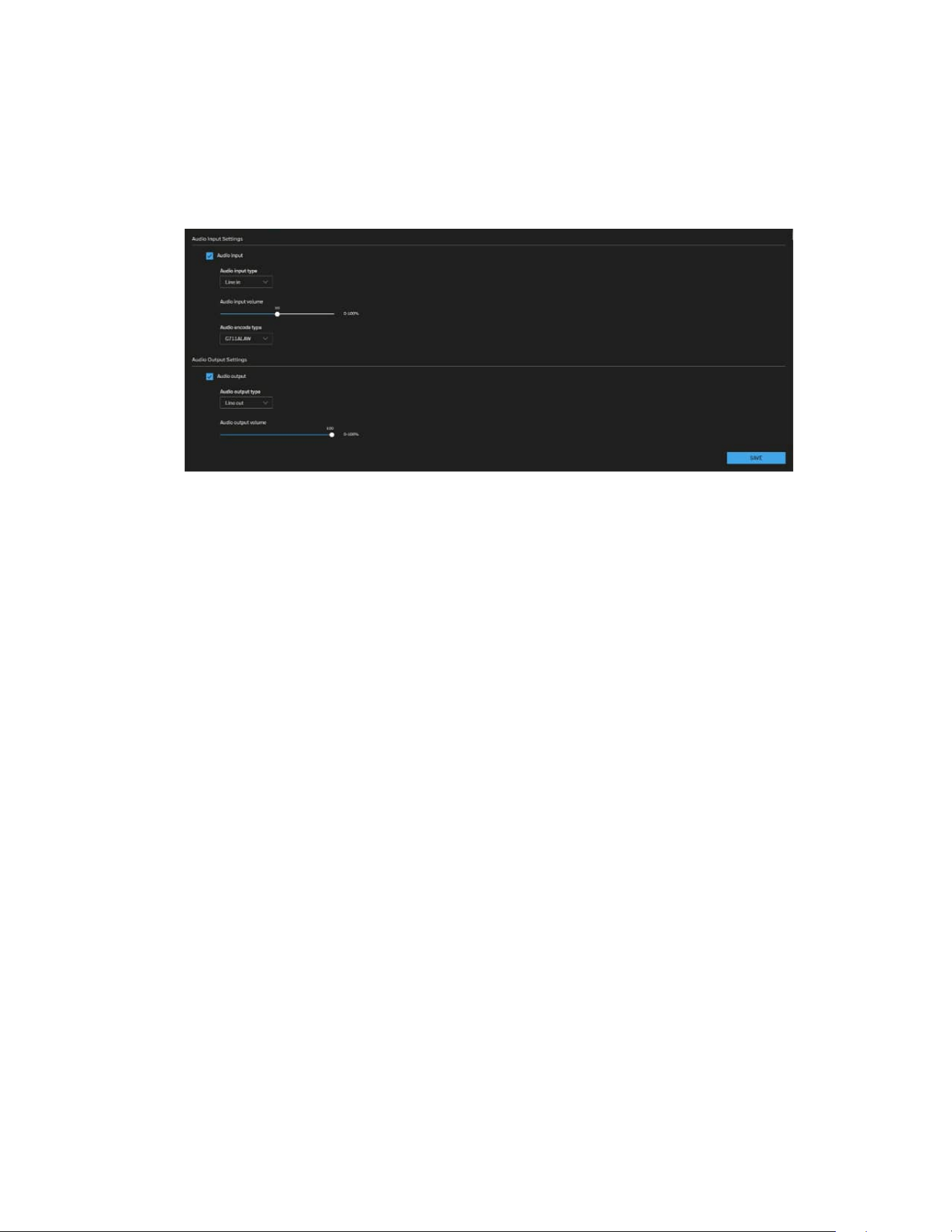
Configuring Audio Settings
Go to Setup > Camera Setup > Audio.
Figure 19 Audio Settings
Audio Input Settings
Audio input: Check the checkbox to enable Audio input.
Audio input type: Select the Microphone or Line-in option.
Note:
The Microphone option is only applicable for Micro Dome cameras.
Audio input volume: Microphone gain or Line-in gain. The Microphone gain or Line-in
gain option is displayed according to the Audio input option selected. Select the gain of
the external audio input according to ambient conditions. Adjust the gain from 0%
(least) to 100% (most).
Audio encode type: Select audio codec as G711ALAW and G711ULAW and the bit rate.
Audio Output Settings
Audio output: Check the checkbox to enable Audio output.
Audio output type: Select the Line-out option.
Audio output volume: The Line-out option is displayed according to the Audio output
option selected. Select the volume of the external audio input according to ambient
conditions. Adjust the volume from 0% (least) to 100% (most).
After you complete the settings on this page, click SAVE to enable the settings.
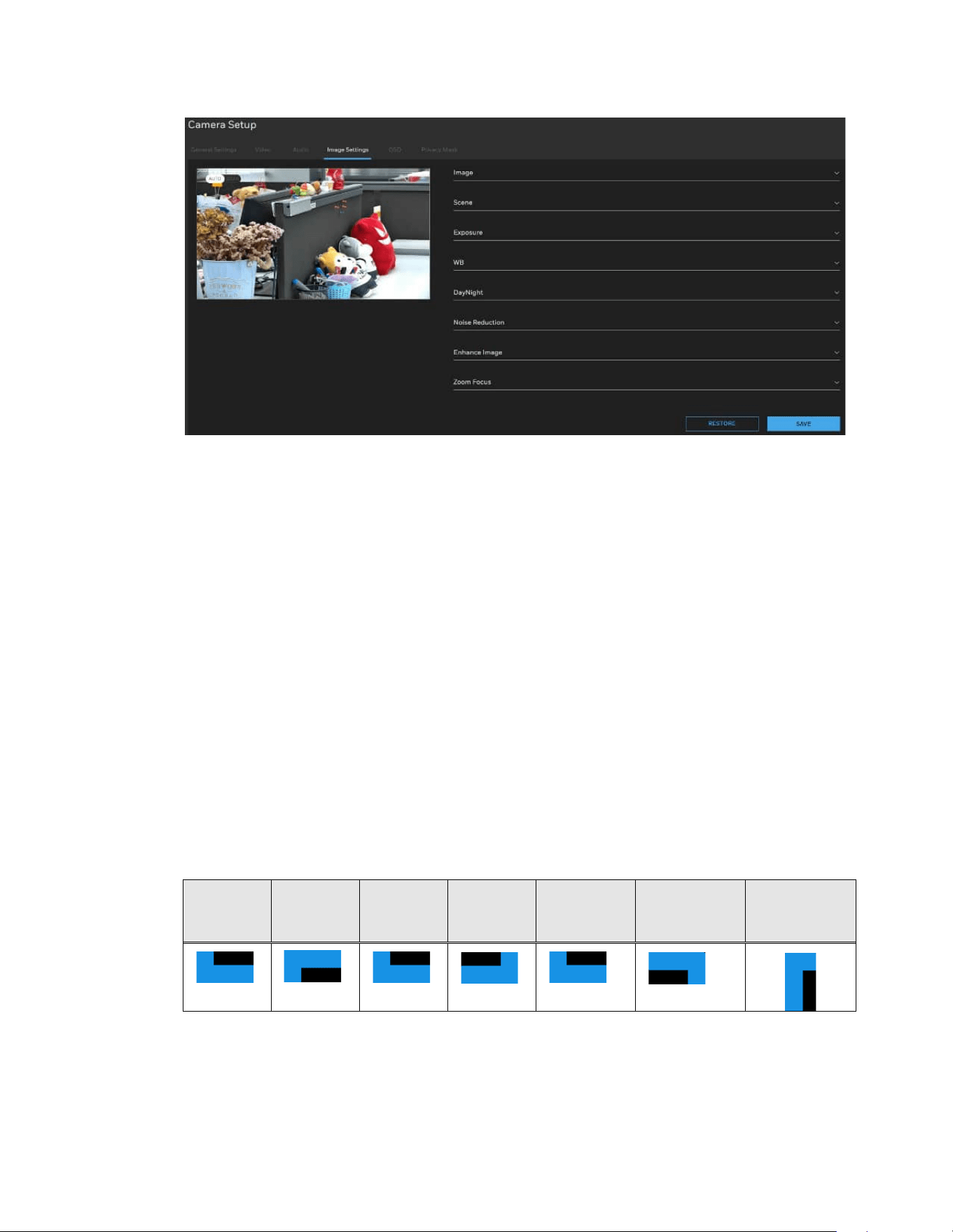
Configuring Image Settings
Go to Setup > Camera Setup > Image Settings.
On this page, you can configure the parameters for Image, Scene, Exposure, WB,
DayNight, Noise Reduction and Enhance Image.
22
Honeywell 35 Series IP Cameras User Guide
Figure 20 Image Settings
Image Adjustment
Brightness: Adjust the image brightness level (0 to 100).
Saturation: Adjust the image saturation level (0 to 100).
Contrast: Adjust the image contrast level (0 to 100).
Sharpness: Adjust the image sharpness level (0 to 100).
Scene Mode
Scene: Select indoor/outdoor to change the scene mode.
Mirror: Select Normal/Horizontal/ Vertical/ Horizontal + Vertical to mirror the image.
Aisle Mode: The image rotates 90 degrees clockwise when aisle mode is enabled.
Note:
•
It will not be able to stream out when the aisle mode is enabled and sub stream or
third stream is set on 352*240 or 320*240.
•
When the aisle mode is enabled, the people counting function is invalid.
Normal
Vertical
Normal
Horizontal
Normal
Horizontal
+ Vertical
Aisle

23
Honeywell 35 Series IP Cameras User Guide
Exposure
Meter area is used to select the exposure area. Select Whole/Center spot/Center area
for different area exposure settings.
Exposure mode: The exposure modes include:
• Auto: The system performs auto exposure based on the monitoring environment.
• Manual: Set Shutter Setting/Iris Setting/Gain Setting to manually adjust the
exposure level for getting the best image quality.
• Shutter priority: you can select fixed shutter and the camera will automatically tune
the gain and iris to match an optimal exposure level. Gain range will be under Max
value.
• IRIS priority: you can select IRIS F-number and the camera will automatically tune
the gain and exposure time to match an optimal exposure level. Gain range and
exposure time will be under Max value.
Max shutter: The device automatically adjusts the shutter time based on the ambient
light under Max value setting.
Max gain: The device automatically adjusts the gain based on the ambient light under
Max value setting.
White Balance (WB) Setting
Mode: Adjust the value for the best color temperature.
• Auto: Select it and the camera will automatically adjust the color temperature.
• Tungsten/ Fluorescent/ Daylight/Shadow: Select it and the camera will change to
Tungsten/ Fluorescent/ Daylight/Shadow color temperature.
Note:
For PTZ models, Tungsten/Daylight color temperature is supported.
• Manual: You may manually tune the color temperature by dragging the R Gain and
B Gain slider.
DayNight Setting
The day night mode settings vary based on device models.
D/N setting: It can be set to Auto, Day mode, Night mode or Timing.
• Auto
The camera automatically removes the filter by judging the level of ambient light.
Note:
Camera will turn on IR LED in night mode if you select IR LED under Light mode.
• Day mode
In day mode, the camera switches on the IR cut filter at all times to block infrared light
from reaching the sensor so that the colors will not be distorted.
• Night mode

24
Honeywell 35 Series IP Cameras User Guide
In night mode, the camera switches off the IR cut filter at all times for the sensor to
accept infrared light, thus helping to improve low light sensitivity.
• Timing
The camera switches between day mode and night mode based on a specified schedule.
Enter the start and end time for day mode. The time format is [hh:mm] and is expressed
in 24-hour clock time. By default, the start and end time of day mode are set to 07:00
and 18:00.
DTN time: Switch time for day mode to night mode
NTD time: Switch time for night mode to day mode
Delay(s): Set the delay time for switching day to night or night to day when the camera
detect to switch.
D/N switch sensitivity: Set the sensitivity for switching day to night/night to day.
Light mode: Select IR led to enable the IR led light. Select None to disable the IR led
light.
IR led:
• Auto: The infrared lamp is enabled or disabled based on the external environment
identified by the light dependent resistor (LDR). Smart IR is supported for Auto.
• Manual: Select it to control the luminance of IR lights manually. For
Near/Center/Far distance, to increase the luminance of IR lights, drag the slider to
the right; to decrease the luminance of IR lights, drag the slider to the left for
different distance.
Noise Reduction
Drag the slider to adjust the reduction strength (from low to high).
2D NR/3D NR: Reduce noise of image.
Max Strength: To get better 3D noise reduction performance, please choose a higher
value to set.
Note:
3D Noise Reduction is mostly applied in low-light conditions. Applying a high level 3D
Noise Reduction will cause lag or motion blur in a low
-light condition with fast moving
objects, suggest to select a lower level of 3D Noise Reduction in this situation
All changes made to image settings are directly shown on screen. To recall the original
settings without incorporating the changes, click RESTORE. After you completed the
settings, click SAVE.
Enhance Image
To enhance image, you can apply the below functions to adjust the image.
Note:
The functions may vary according to different camera models.

25
Honeywell 35 Series IP Cameras User Guide
WDR (Wide Dynamic Range)
By lowering the brightness of the brightest area, and enhancing the brightness of the
darkest area, WDR balances brightness and darkness in a scene so that both the
darkest area and the lightest area can be seen clearly at the same time.
This value ranges from 1 to 100. The default value is 50.
BLC (Backlight Compensation)
The camera automatically adjusts the exposure to suit the conditions, so that the
darkest area of the video can be seen.
This value ranges from 1 to 100. The default value is 50.
HLC (Highlight Compensation)
When the HLC function is enabled, the camera can lower the brightness of the brightest
section of video, according to the selected HLC control level. HLC can reduce the
amount of halo and lower the brightness of the entire video image.
This value ranges from 1 to 100. The default value is 50.
DeFog: Check the checkbox to enable defog. The image quality is compromised in foggy
or hazy environment and defog can be used to improve image clarity.
Anti-shake: Check the checkbox to enable Anti-shake.
The system provides smooth video (Electronic Image Stabilization) after enabling anti-
shake. The quality of the images is affected by the vibration intensity of the camera.
Note:
The Anti-shake functions is only applicable for PTZ model HC35WZ2R25 and
HC35WZ5R30.
Configuring OSD
Go to Setup > Camera Setup > OSD. The OSD page is displayed,
Time: Enable it to display time information in live view image.
Video title: Enable and enter video title to display video title in live view image.
( for PTZ model only) PTZ coordinates: Enable to display PTZ coordinates when moving
PTZ.
Position: Set the OSD display+ position.
Font size: Set the font size of OSD display.
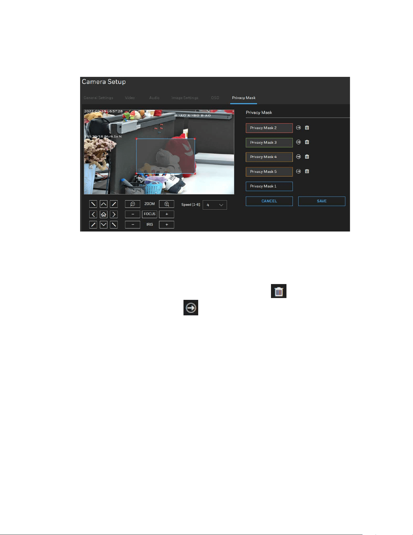
Configuring Privacy Mask
On this page, you can block out sensitive view areas to address privacy concerns. Go to
Setup > Camera Setup > Privacy Mask.
To configure privacy masks:
1. Click ADD MASK to add a new privacy mask window on the video screen.
26
Honeywell 35 Series IP Cameras User Guide
2. Drag the corner of the rectangle to create a new masking window.
3. Enter a name for the privacy mask and click SAVE to enable the setting.
Figure 21 Privacy Mask
Note:
•
The object should be in the middle of the video screen and the setting size of
privacy mask should be 1.5~2.5 times of the object size.
•
Up to 4/5 privacy mask windows for IPC/PTZ cameras can be configured on the
same screen.
•
If you want to delete the privacy mask window, click
on the right side of privacy
mask window name. Click to go to the relate privacy mask position.
CHAPTER
27
Honeywell 35 Series IP Cameras User Guide
5 CONFIGURING NETWORK
SETTINGS
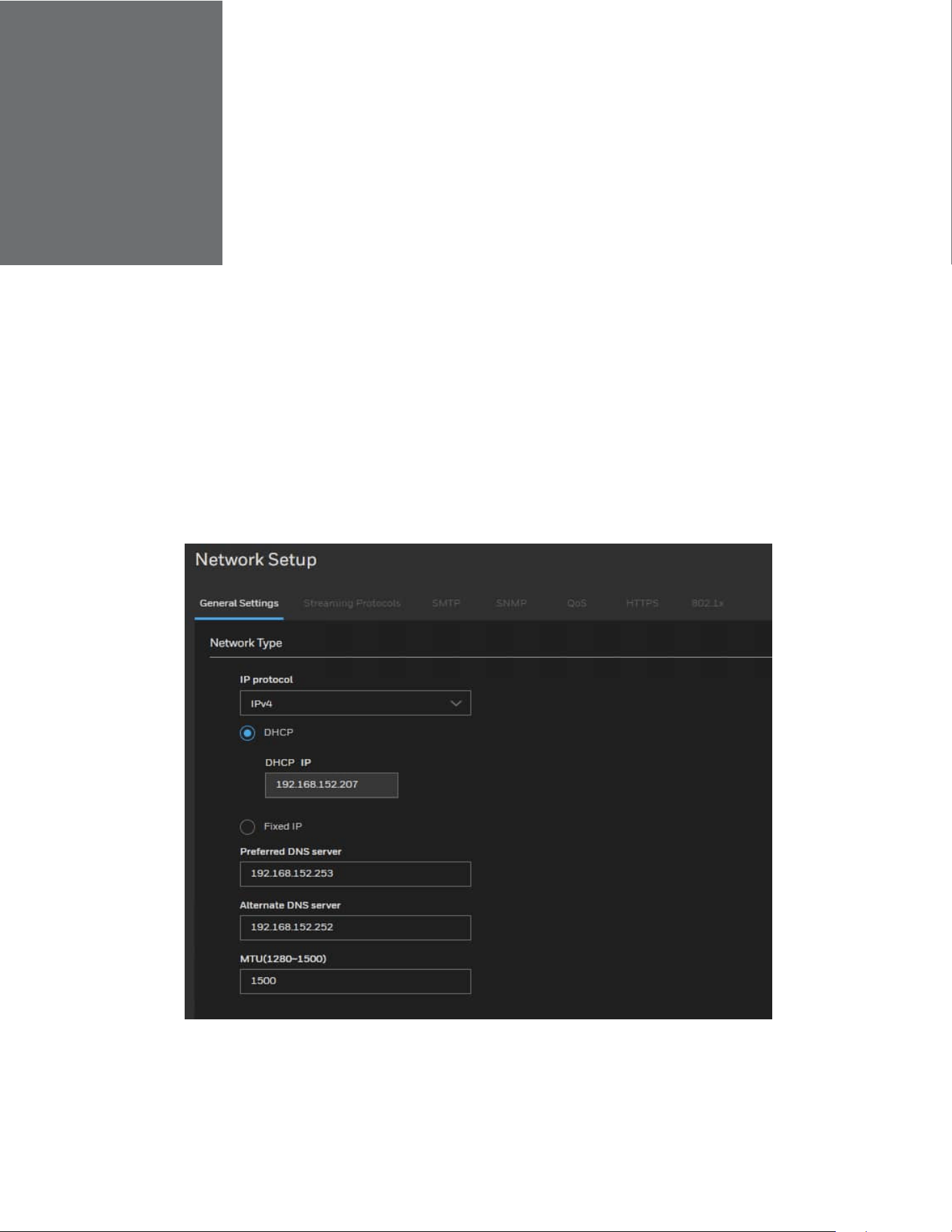
Configuring Network General Settings
This section describes how to configure a wired network connection for the camera.
Go to Setup > Network Setup > General Settings.
Figure 22 Network General Settings
Select IPv4/IPv6 for IP protocol.
When IPv4/IPv6 is enabled, by default, the network camera will listen to router
advertisements and be assigned with a link-local IPv4/IPv6 address accordingly.
28
Honeywell 35 Series IP Cameras User Guide
DHCP: Select this option to obtain an available dynamic IP address assigned by the
DHCP server each time the camera is connected to the LAN.
Fixed IP: Select this option to manually assign a static IP address to the camera.
IP address:
You can make use of Unified Tool in the software CD to easily set up the camera on LAN.
See Accessing the Camera on page 4.
Enter the Static IP, Subnet mask, Default gateway, and Primary DNS provided by your
ISP or network administrator.
Subnet mask: This is used to determine if the destination is in the same subnet. The
default value is “255.255.255.0”.
Default gateway: This is the gateway used to forward frames to destinations in a
different subnet. Invalid router setting will disable the transmission to destinations
across different subnets.
Preferred DNS Server: The primary domain name server that translates hostnames into
IP addresses.
Alternate DNS Server: Secondary domain name server that backups the Primary DNS.
MTU (1280~1500): Set the maximum value of network transmission data packets.
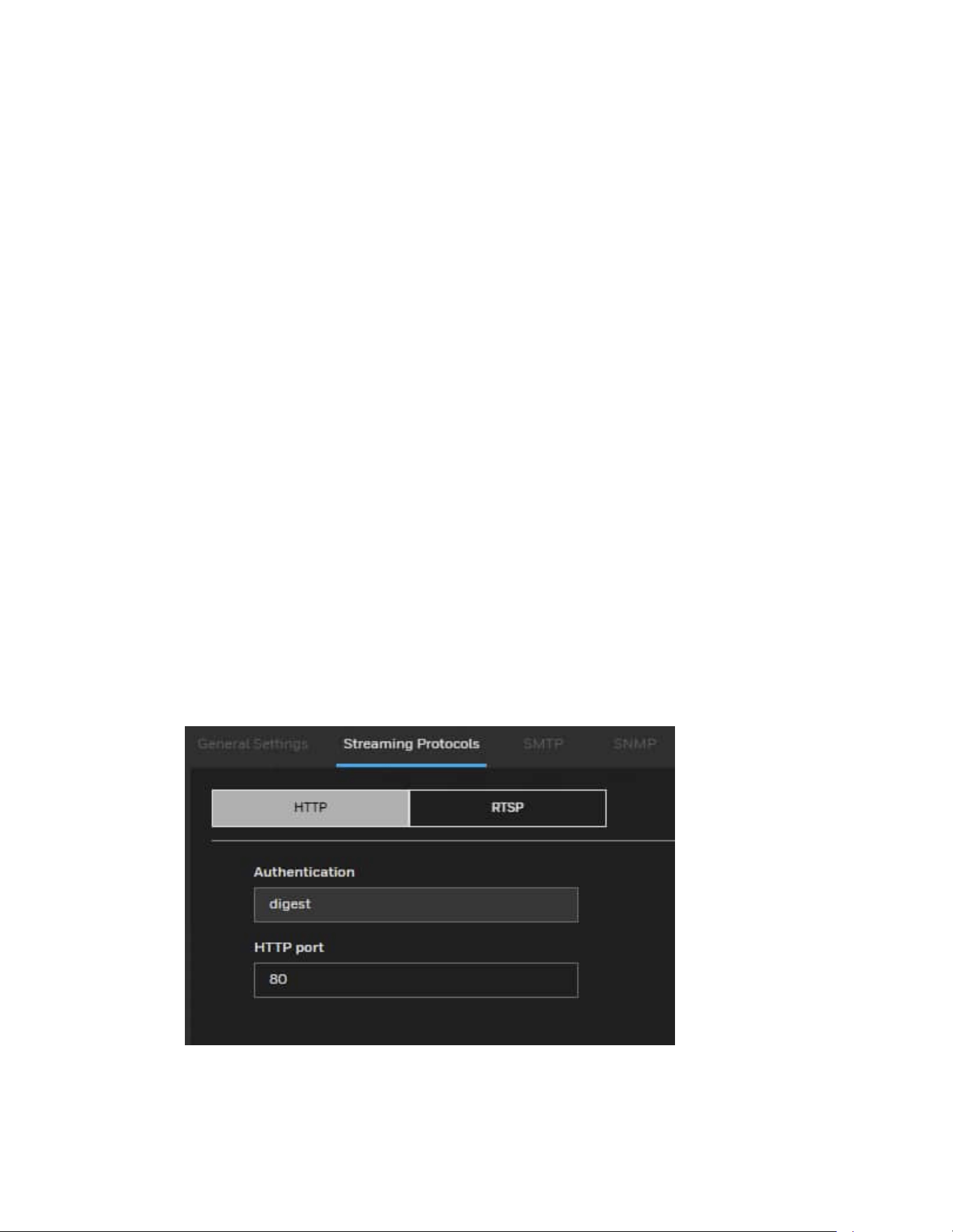
Configuring Streaming Protocols
Go to Setup > Network Setup > Streaming Protocols.
Figure 23 Streaming Protocols-HTTP
To utilize HTTP authentication, make sure that you have set a password for the camera
first. For more information, see Configuring User Accounts Settings on page 56.
29
Honeywell 35 Series IP Cameras User Guide
Authentication: User credentials are encrypted with MD5 algorithm which provide
better protection against unauthorized accesses.
HTTP port: By default, the HTTP port is set to 80. It can also be assigned to another port
number between 1025 and 65535.
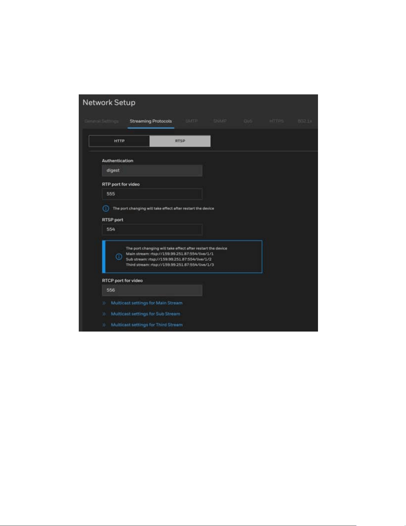
Figure 24 Streaming Protocols-RTSP
To utilize RTSP streaming authentication, make sure that you have set a password for
controlling the access to video stream first. For more information, see Configuring User
Accounts Settings on page 56.
Authentication: Authentication provides better protection against unauthorized access.
If you want to use an RTSP player to access the camera, you have to set the video mode
to H.264 or H.265 and use the following RTSP URL command to request transmission
of the streaming data.
Use rtsp://IP address: Port/live/Camera ID/Streaming ID for pulling RTSP streaming.
Note:
IP address: The device IP address
Port: RTSP port, default is 554
Live: Keep Live as default.

30
Honeywell 35 Series IP Cameras User Guide
Camera ID: 1
Streaming ID: 1 for Mainstream, 2 for Sub stream, 3 for 3rd stream.
For example: Follow below step to stream out rtsp streaming.
1. Launch an RTSP player.
2. Choose File > Open URL. A URL dialog box will pop up.
3. Type the below URL command in the text box for each stream.
Mainstream: rtsp://192.168.0.108:554/live/1/1
Sub stream: rtsp://192.168.0.108:554/live/1/2
Third stream: rtsp://192.168.0.108:554/live/1/3
4. The live video will be displayed in your player.
RTSP port /RTP port for video / RTCP port for video:
• The RTP (Real-time Transport Protocol) is used to deliver video data to the clients. By
default, the RTP port for video is set to 555.
• RTSP (Real-Time Streaming Protocol) controls the delivery of streaming media. By
default, the RTSP port number is set to 554.
• The RTCP (Real-time Transport Control Protocol) allows the camera to transmit the
data by monitoring the Internet traffic volume. By default, the RTCP port for video is
set to 556.
The ports can be changed to values between 1025 and 65535. The RTP port must be an
even number and the RTCP port is the RTP port number plus one, and thus is always an
odd number. When the RTP port changes, the RTCP port will change accordingly.
Multicast settings for streams: Click to display the detailed configuration information.
Multicast group address: Enter the Multicast group address.
Multicast video port: The ports can be changed to values between 1025 and 65535.
The default value is 25330.
Multicast audio port: The ports can be changed to values between 1025 and 65535.
The default value is 25430.
Multicast metadata port: The ports can be changed to values between 1025 and
65535. The default value is 25530
Multicast TTL: The multicast TTL (Time To Live) is the value that tells the router the
range a packet can be forwarded. The default value is 60.
Note:
Multicast is enabled by default in camera.
31
Honeywell 35 Series IP Cameras User Guide
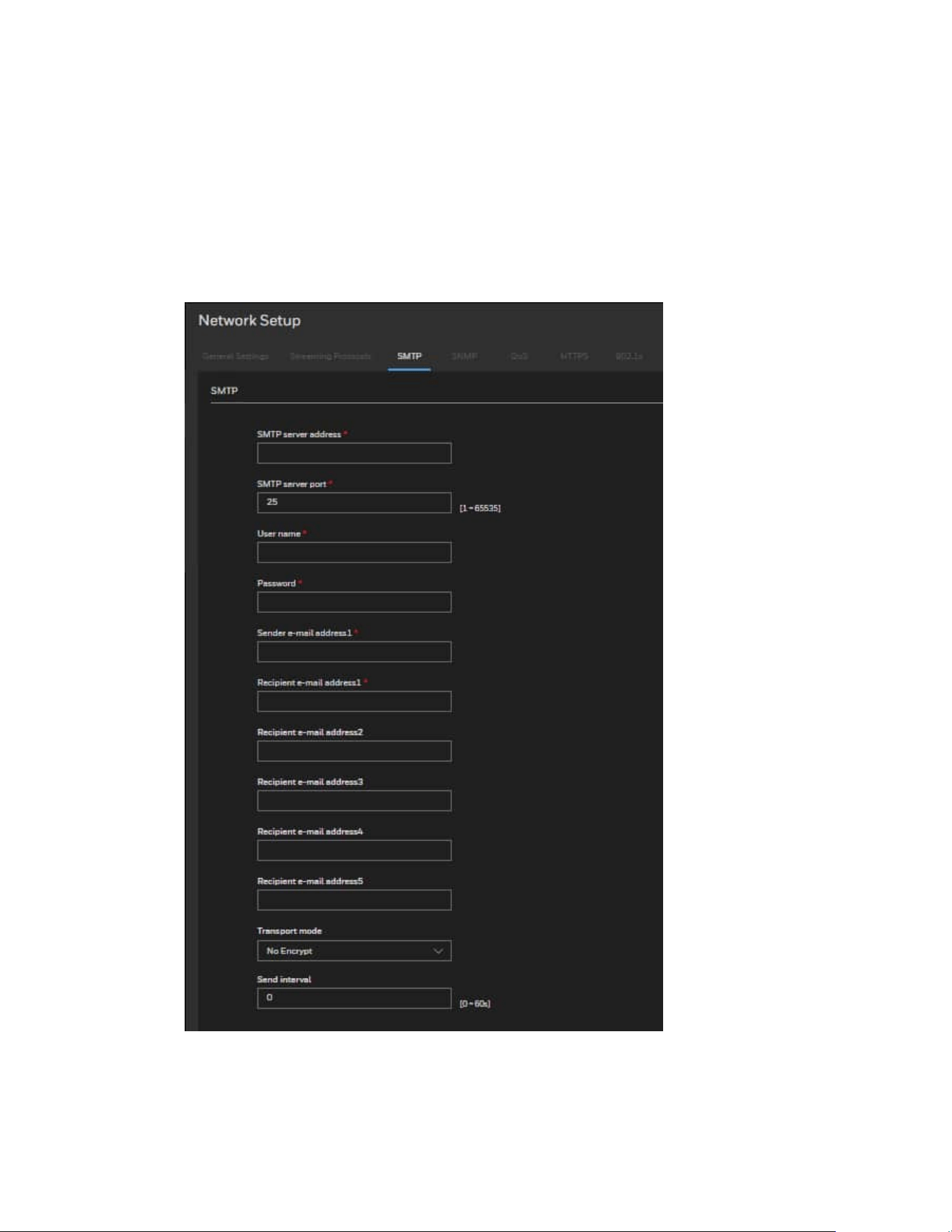
Configuring SMTP Settings
If the Simple Mail Transfer Protocol (SMTP) function is enabled, the device
automatically sends JPG images and alarm information to specified email addresses
when an alarm is generated.
Go to Setup > Network Setup > SMTP.
Figure 25 SMTP Settings
SMTP server address: IP address of the SMTP server.
SMTP server port: Port number of the SMTP server.

32
Honeywell 35 Series IP Cameras User Guide
User name: User name of the mailbox for sending emails.
Password: Password of the mailbox for sending emails.
Sender e-mail address1: Mailbox for sending emails.
Recipient_e-mail_address1: Email address of recipient 1.
Recipient_e-mail_address2: Email address of recipient 2.
Recipient_e-mail_address3: Email address of recipient 3.
Recipient_e-mail_address4: Email address of recipient 4.
Recipient_e-mail_address5: Email address of recipient 5.
Transport mode: Email encryption mode. Set this parameter based on the encryption
modes supported by the SMTP server.
Send interval: The interval for sending ranges from 0 to 60 seconds. The system will not
immediately send the email when the alarm occurs. When an alarm, motion detection, or
other event occurs to activate an email, the system sends one email within the interval
that you have specified here. This reduces the load on the email server when multiple
emails are triggered simultaneously.
Configuring SNMP Settings
Go to Setup > Network Setup > SNMP.
SNMP (Simple Network Management Protocol) is a protocol for collecting, organizing,
and exchanging management information between managed devices on a network.
The SNMP consists of the following three key components:
• Manager: Network-management station (NMS), a server which executes applications
that monitor and control managed devices.
• Agent: A network-management software module on a managed device which
transfers the status of managed devices to the NMS.
• Managed device: A network node on a managed network. For example: routers,
switches, bridges, hubs, computer hosts, printers, IP telephones, network cameras,
web server, and database.
Before configuring SNMP settings on the page, enable your NMS first.
Enable SNMPv1, SNMPv2c: Check to enable SNMPv1, SNMPv2c. SNMPv1 and
SNMPv2c use communities to establish trust between managers and agents. Agents
support three community names, write community, read community and trap.
Write community: Name of write community. The write community only can modify
data.
Read community: Name of read community. The write community only can read data.

33
Honeywell 35 Series IP Cameras User Guide
Trap address: IP address of the trap.
Trap port: Management port of accepting message from trap.
Trap community: community string of trap. The trap community string allows the
manager to receive asynchronous information from the agent.
Enable SNMPv3: Check to enable SNMPv3 which contains cryptographic security, a
higher security level.
SNMPv3 uses community strings but allows for secure authentication and
communication between SNMP manager and agent.
Read security name: Name of read security.
Write security name: Name of write security.
Security level: Security Level between SNMP manager and agent, includes three levels:
• Noauth: No authentication and no encryption
• Auth: Authentication but no encryption
• Priv: Authentication and encryption
Auth algorithm: Authentication Algorithm, includes MD5and SHA.
Auth password: Authentication password.
Encry Algorithm: Encryption Algorithm, includes DES and AES.
Encry Password: Encryption password.
SNMP Port: Port of SNMP.
Configuring QoS Settings
Go to Setup > Network Setup > QoS.
Quality of Service (QoS) is a network security mechanism. It fixes problems with network
delays and jams. For network service, the quality of service includes the transmission
bandwidth, delay, and packet loss, for example. Through QoS, you can guarantee the
transmission bandwidth, reduce the delay, reduce the loss of data packets, and enhance
the transmission quality with packet prioritization.
To utilize QoS in a network environment, the following requirements must be met:
• All network switches and routers in the network must include support for QoS.
• The network video devices used in the network must be QoS-enabled.
34
Honeywell 35 Series IP Cameras User Guide
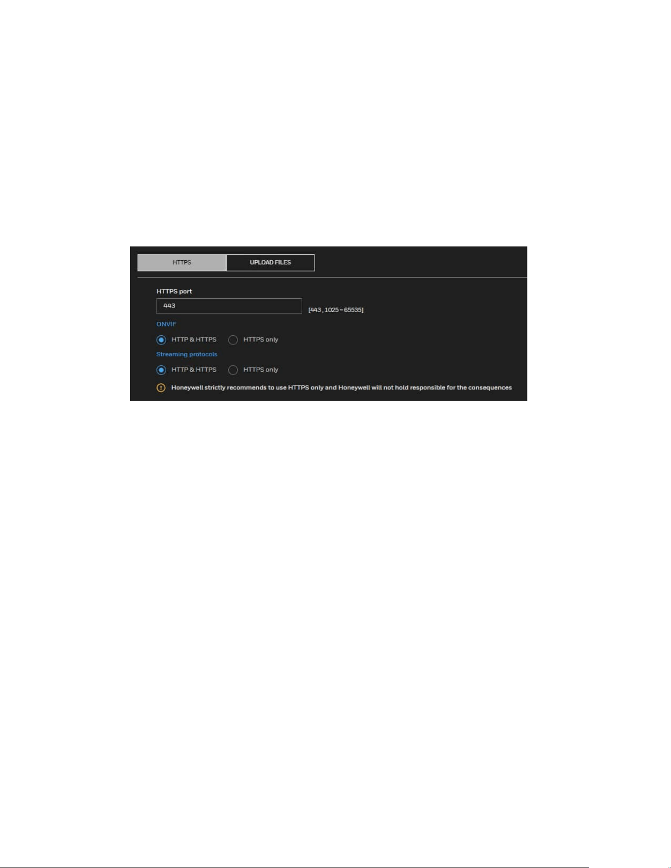
Configuring HTTPS Settings
HTTPS
Go to Setup > Network Setup > HTTPS > HTTPS.
This section explains how to enable authentication and encrypted communication. It
helps protect streaming data transmission over the Internet on higher security level.
Figure 26 HTTPS Settings
Note:
Honeywell strictly recommends using HTTPS only.
HTTP & HTTPS: Select it and the web browser can be accessed via HTTP or HTTPS.
HTTPS only: Select it and the web browser can only be accessed via HTTPS with higher
security level.
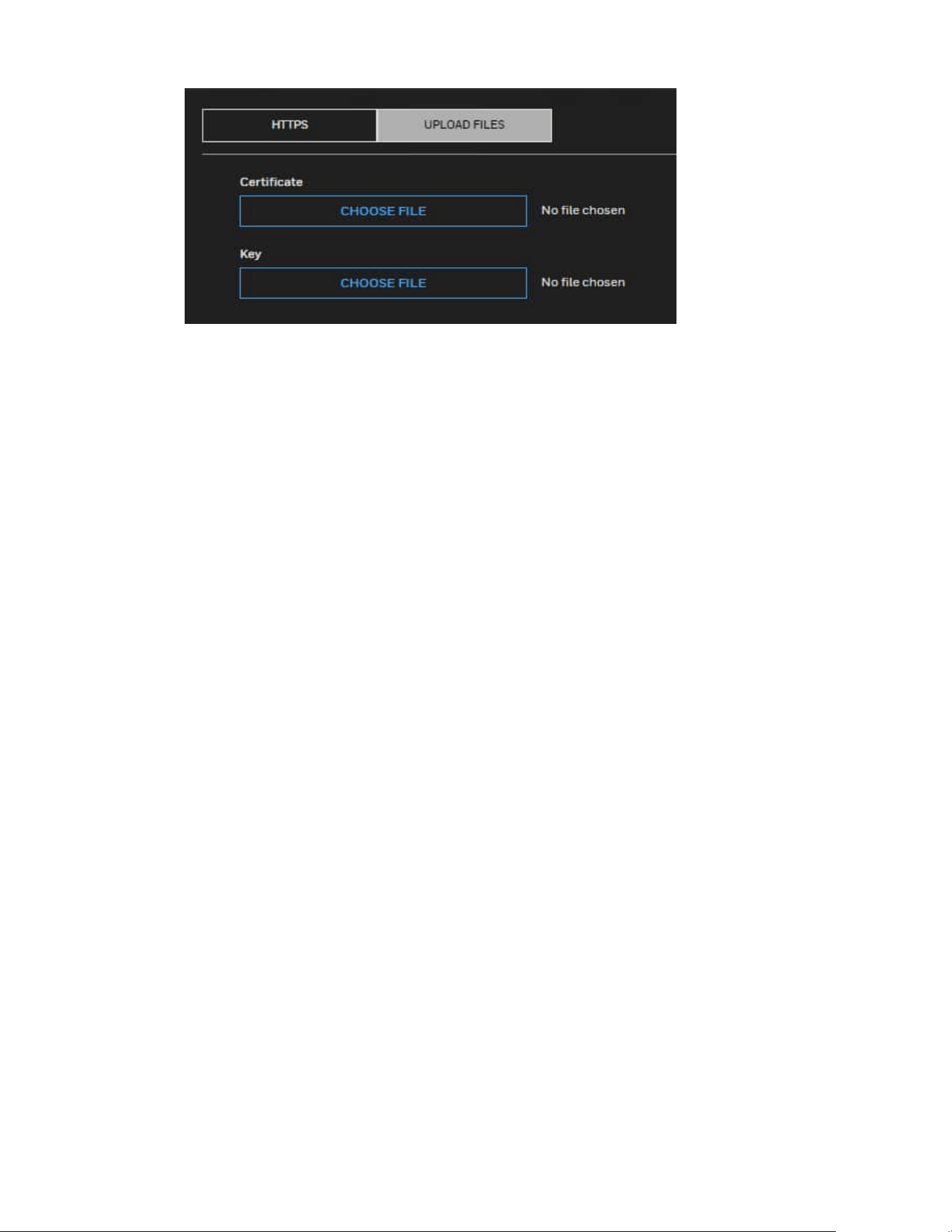
Upload Files
Go to Setup > Network Setup > HTTPS > UPLOAD FILES. You can import the certificate
from third party here.
35
Honeywell 35 Series IP Cameras User Guide
To import the certificate from third party:
1. In the Certificate field, click CHOOSE FILE to select a certificate file you have
already applied from 3rd party or CA domain.
2. In the Key field, click CHOOSE FILE to select a certificate key you have already
applied from 3rd party or CA domain.
3. Click UPLOAD and reboot camera.
After the certificate file is uploaded successfully, if you want to remove the certificate,
click REMOVE.
• Supported certificate type: HTTPS protocol.
• Supported certificate file format: *.cert format.
• Supported Key format: PEM format.
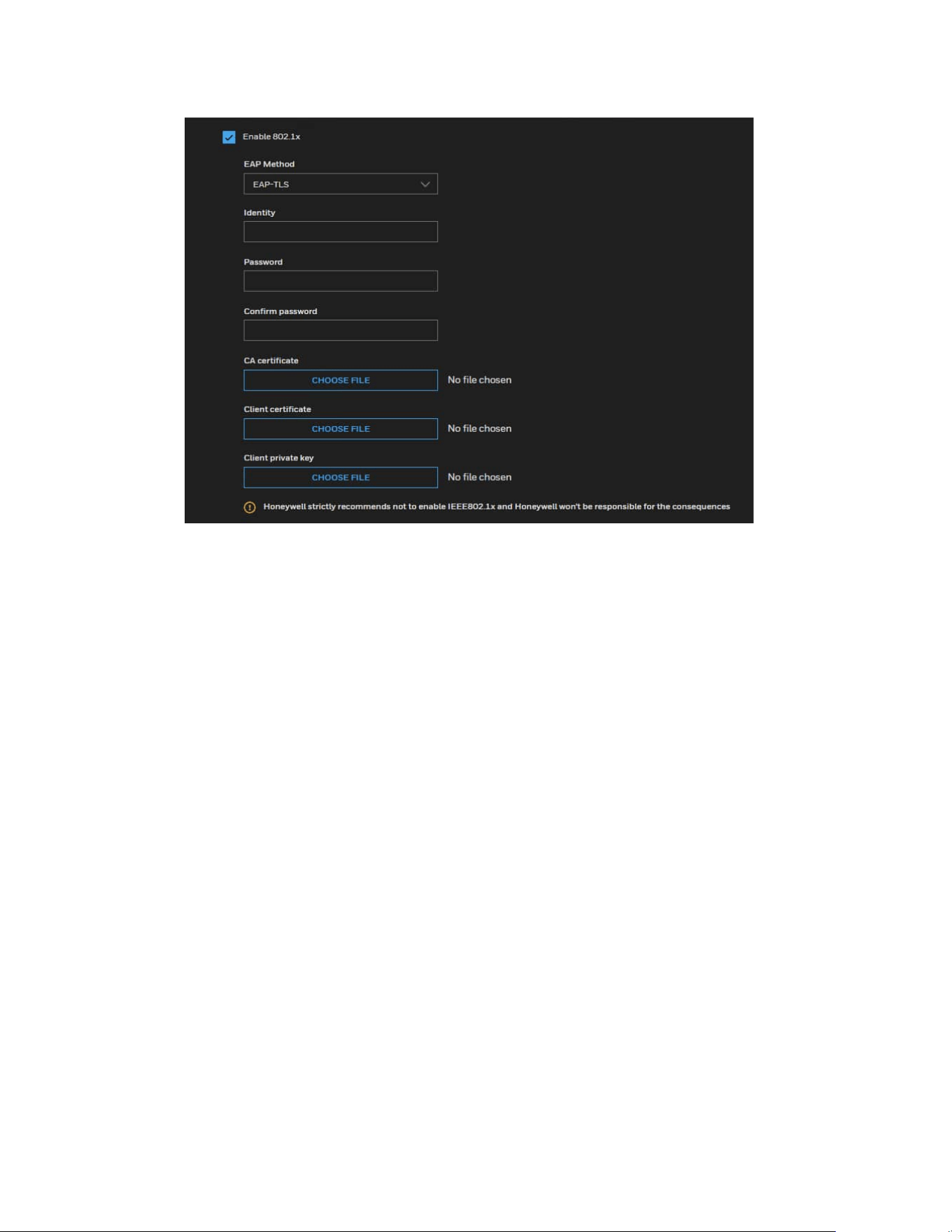
Configuring IEEE 802.1x Settings
Go to Setup > Network Setup > 802.1x.
IEEE802.1x is the access control and authentication protocol for local and metropolitan
area networks. It uses a port-based network access control protocol to restrict
unauthorized user and/or device access to the LAN. The network devices, intermediary
switch/access point/hub, and RADIUS server must support and enable 802.1x settings.
To configure IEEE 802.1x settings:
1. Before connecting the camera to the protected network with 802.1x, apply a
digital certificate from a Certificate Authority (i.e., your network administrator)
which can be validated by a RADIUS server.
2. Connect the camera to a PC or notebook outside of the protected LAN. Open the
configuration page of the camera as shown below.
36
Honeywell 35 Series IP Cameras User Guide
Figure 27 IEEE 802.1x Configurations – EAP-TLS
Note:
Honeywell doesn’t recommend enabling IEEE 802.1x.
Select EAP-TLS as the EAP method. Enter your ID and password issued by the CA, and
then upload related certificate(s).
3. When all settings are complete, move the camera to the protected LAN by
connecting it to an 802.1x enabled switch. The devices will then start the
authentication automatically.
CHAPTER
37
Honeywell 35 Series IP Cameras User Guide
6 CONFIGURING VIDEO ANALYTICS
Video Analytics provides the following features: motion detection, smart motion,
tampering, intrusion, multi loitering and people counter.
Video Analytics detects one or a group of the following objects:
• Vehicle
• Human
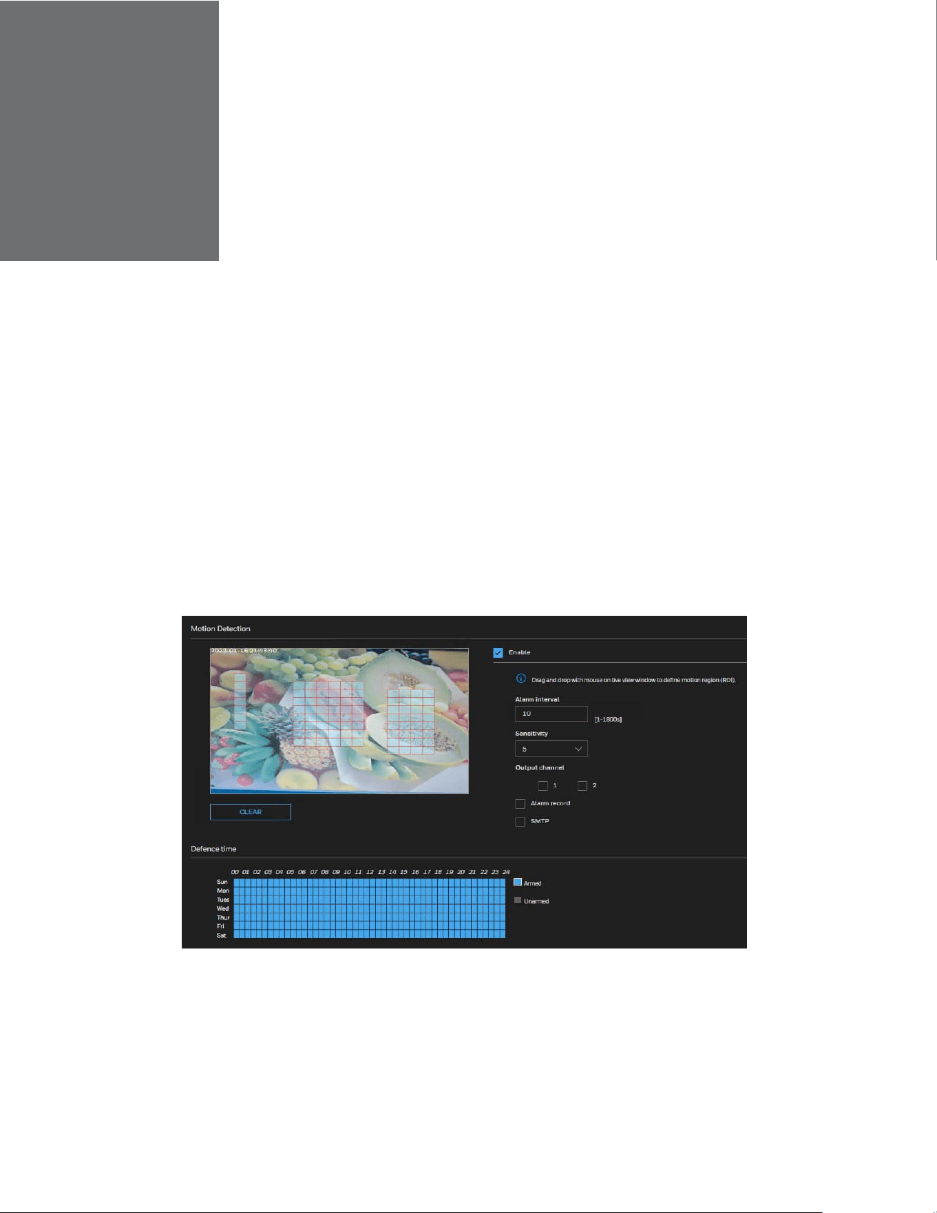
Motion Detection
1. Go to Setup > Video Analytics > Motion Detection.
Figure 28 Motion Detection
2. Check the Enable checkbox to enable motion detection.
3. Configure the Alarm interval and Sensitivity.
4. Configure the detection area.
• Press and hold the left mouse button, and drag in the video area to draw a
38
Honeywell 35 Series IP Cameras User Guide
detection area
• Click ClEAR to delete a detection area.
5. Select the Output channel.
6. Check the check boxes to enable Alarm record and SMTP.
7. Click SAVE.
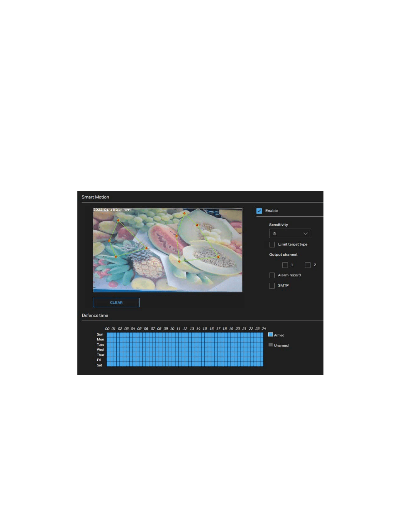
Smart Motion Detection
Smart Motion detection identifies one or more detection objects (human, pat, vehicle) in
motion. The applicable scenario includes motion of humans in a restricted area.
1. Go to Setup > Video Analytics > Smart Motion.
Figure 29 Smart Motion
2. Check the Enable checkbox to enable smart motion detection.
3. Configure the Sensitivity.
4. Configure the detection area.
• Press and hold the left mouse button, and drag in the video area to draw a
detection area
• Click CLEAR to delete a detection area.
5. Select the Output channel.
39
Honeywell 35 Series IP Cameras User Guide
6. Check the check boxes to enable Alarm record and SMTP.
7. Click SAVE.
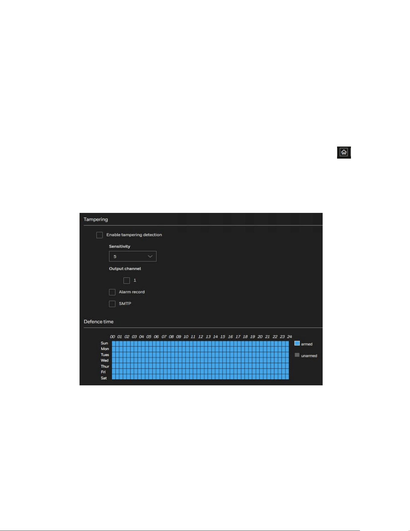
Tampering Detection
Tampering detection identifies the camera tampering based on a set tampering
sensitivity value.
Note:
All VA functions are disabled because camera is not on home position. Click
to go
home position before setting Tampering.
1. Go to Setup > Video Analytics > Tampering.
Figure 30 Tampering Detection
2. Check the Enable checkbox to enable tampering detection.
3. Configure the Sensitivity.
4. Configure the detection area.
• Press and hold the left mouse button, and drag in the video area to draw a
detection area
• Click CLEAR to delete a detection area.
5. Select the Output channel.
40
Honeywell 35 Series IP Cameras User Guide
6. Check the check boxes to enable Alarm record and SMTP.
7. Click SAVE.
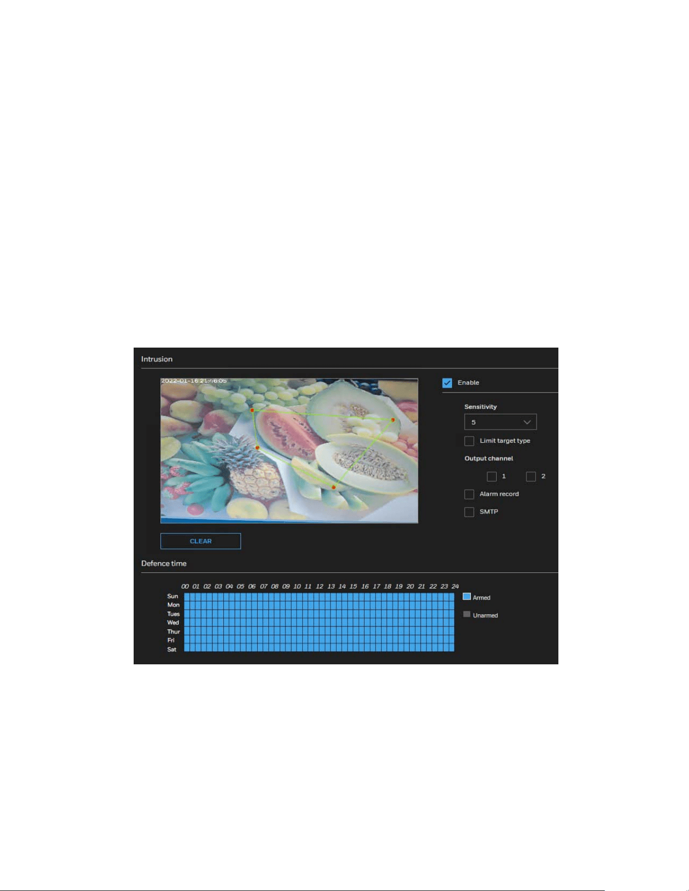
Intrusion Detection
Intrusion Detection can be used to detect objects entering or leaving a virtual area in the
camera field of view.
The applicable scenarios of this feature can be:
• Detects when a person enters a bank vault or school after the office hours.
• Detects when a person leaves an emergency exit or fire escape, or any place that is
normally forbidden from access.
1. Go to Setup > Video Analytics > Intrusion.
Figure 31 Intrusion Detection
2. Check the Enable checkbox to enable intrusion detection.
3. Configure the Sensitivity.
4. Configure the detection area.
• Press and hold the left mouse button, and drag in the video area to draw a
detection area
• Click CLEAR to delete a detection area.
41
Honeywell 35 Series IP Cameras User Guide
5. Select the Output channel.
6. Check the check boxes to enable Alarm record and SMTP.
7. Click SAVE.
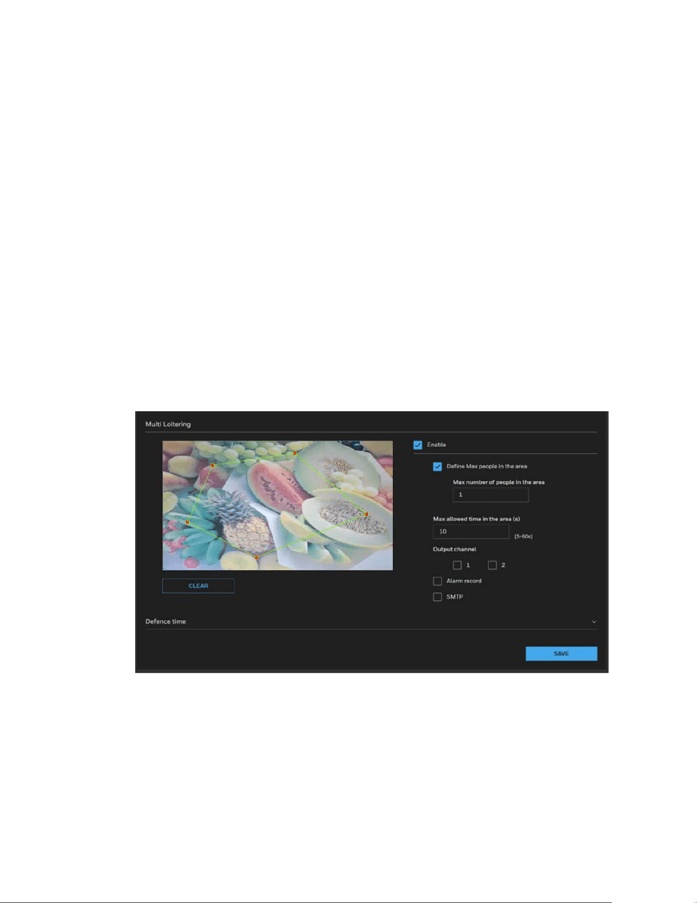
Multi Loitering
The Loitering detection can be used for a detection object or a group of detection
objects lingering in an area for longer than a preset time threshold.
The applicable scenarios of this feature can be:
• Detects when a person is loitering at a walk-up of ATM lane.
• Detects when a person is loitering in a high-theft area of a store, or to prevent
vandalism and break-ins.
• Detects when a person is loitering in an area that is normally not an access for
visitors.
1. Go to Setup > Video Analytics > Multi Loitering.
Figure 32 Multi Loitering
2. Check the Enable checkbox to enable multi loitering detection.
3. Check the checkbox of Define Max people in the area.
4. Configure Max number of people in the area.
5. Configure Max allowed time in the area (s).
6. Configure the detection area.
• Press and hold the left mouse button, and drag in the video area to draw a
detection area
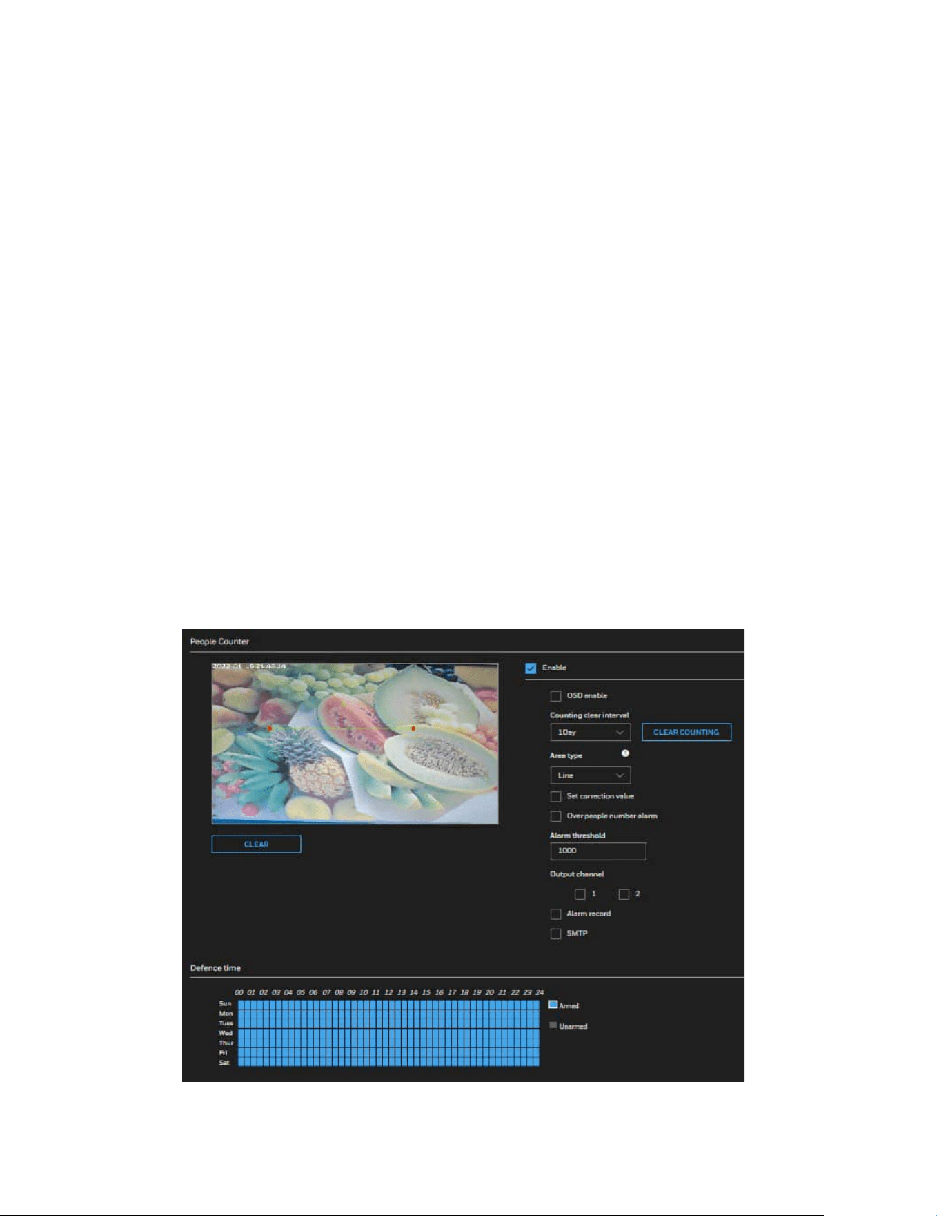
42
Honeywell 35 Series IP Cameras User Guide
• Click CLEAR to delete a detection area.
7. Select the Output channel.
8. Check the check boxes to enable Alarm record and SMTP.
9. Click SAVE.
People Counter
People Counter detects the presence of human faces in the field of view. The applicable
scenarios of this feature can be:
By tagging the video frames which contain facial features, the administrator can later
search for the video clips with the presence of these faces in a more efficient manner.
Instead of searching through hours of recordings, face detection can facilitate the
process of forensic search in recorded videos. Objects irrelevant to facial features will be
filtered out.
Note:
When the aisle mode is enabled, the people counting function is invalid.
1. Go to Setup > Video Analytics > People Counter.
Figure 33 People Counter

43
Honeywell 35 Series IP Cameras User Guide
2. Check the Enable checkbox to enable people countering.
3. Configure the detection area.
• Press and hold the left mouse button, and drag in the video area to draw a
detection area
• Click CLEAR to delete a detection area.
4. Check the OSD enable checkbox to enable OSD display of people countering.
5. Configure the Countering clear interval, Area type and Alarm threshold.
a Select interval time to configure the Countering clear interval, the camera will
clear counting numbers within every setting time interval. Click CLEAR
COUNTING to clear current counting number.
b Check the enable checkbox of Set correction value to enable counting
correction which already stay on the In area. Input people number which is
already stay in the In area.
c Check the enable checkbox of Over people number alarm to enable alarm
function when stay people number over the number setting in Alarm
threshold box.
6. Select the Output channel.
7. Check the check boxes to enable Alarm record and SMTP.
8. Click SAVE.
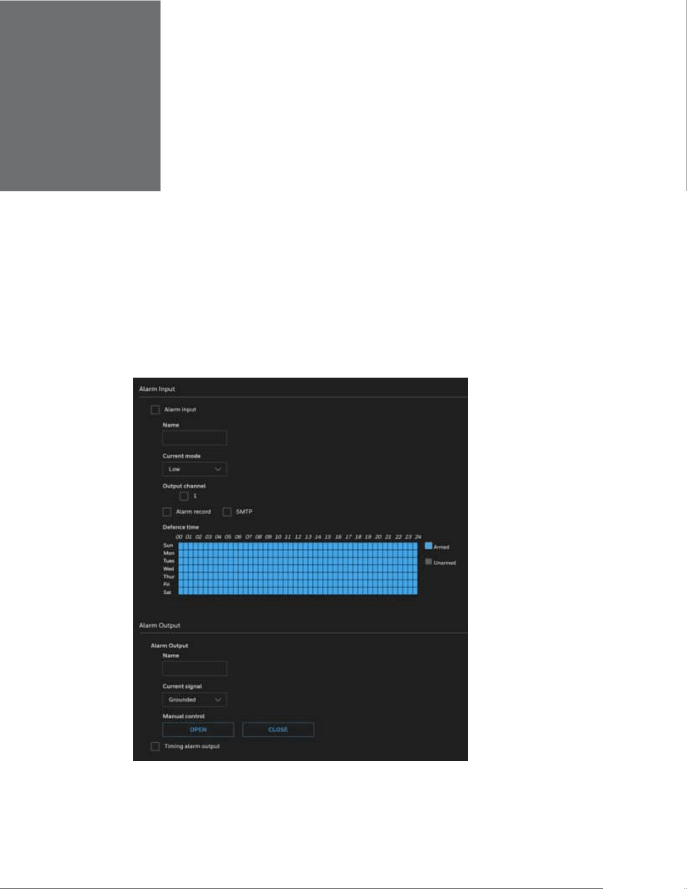
CHAPTER
44
Honeywell 35 Series IP Cameras User Guide
7 CONFIGURE ALARM AND EVENT
This section describes the alarm and event settings.
Configuring Alarm In and Alarm Out
Go to Setup > Alarm & Event > Alarm In and Alarm Out.
Figure 34 Alarm In and Alarm Out

45
Honeywell 35 Series IP Cameras User Guide
Alarm Input
Alarm input: Check the checkbox of Alarm input.
Name: Enter the alarm input name.
Current mode: Select the current mode from the drop-down list box.
Defence time: Configure the schedule by using one of the methods below.
Click left mouse button to select any time point within 0:00-24:00 from Monday to
Sunday.
Hold down the left mouse button, drag and release mouse to select the schedule
within 0:00-24:00 from Monday to Sunday.
Output channel: Select the Output channel.
Alarm record/SMTP: Check the check boxes to enable Alarm record and SMTP.
PTZ linkage: Check the check boxes to enable PTZ linkage.
After the event is triggered, the system will run or stop the movement of the
corresponding type according to the settings.
PTZ type: Select Preset/Scan/Patrol/Recording Patrol.
Value: Select the value.
Operate: Select Invoke/Pause/Continue when PTZ type is Patrol.
- Invoke: Call related PTZ linkage for running Patrol.
- Pause: Pause related PTZ linkage Patrol.
- Continue: Continue related PTZ linkage running Patrol.
Note:
PTZ linkage function is only applicable for PTZ models HC35WZ2R25/HC35WZ5R30/
HC35WZ5R30W.
Alarm Output
Name: Alarm output name
Current Signal: Select Grounded or Open to define normal status for the alarm output.
Connect the output cable to an external device, the camera will report the current signal
output status according to alarm event setting.
Grounded: Camera alarm relay is Normal Open. It will turn to Grounded/Closed
when an alarm event is generated to trigger it.

46
Honeywell 35 Series IP Cameras User Guide
Open: Camera alarm relay is Normal Closed (Grounded). It will turn to Open state
when an alarm event is generated to trigger it.
Note:
The signal status will take effect after one alarm out is triggered.
Manual control: If alarm out signal is coming, click Close to disable alarm out or click
Open to keep alarm out status.
If alarm out signal is not coming, it is opposite with above.
Timing alarm output: Enable Timing alarm output and set time for alarm out. The
device will continue trigger alarm out during the selecting time slot.
Note:
For 5M/8M models
(HC35WX5RX/HC35WX8RX), an alarm input and an alarm output
can be configured.
For PTZ models HC35WZ5R30/HC35WZ2R25, alarm input1/input2 and alarm
output1/ output2 can be configured.
For PTZ model HC35WZ5R30W, alarm input1~7, and alarm output1/ output2 can be
configured.
Configuring SD Card Alarm
Go to Setup > Alarm & Event > SD Card Alarm.
SD card alarm: Check the checkbox to enable SD card alarm.
Alarm threshold(used space): The camera will alarm when used space achieves the
alarm threshold.
Alarm interval: Set the interval.
Output channel: Check the checkbox to set the Output channel

CHAPTER
47
Honeywell 35 Series IP Cameras User Guide
8 CONFIGURE STORAGE SETTINGS
SD Card Management
Go to Setup > Storage Setup > SD Card Management.
This section describes how to manage the local storage on the camera. Here you can
view SD card status, and implement SD card control.
See the following table for compatible SD Card.
Table 4 Compatible SD Card
SD Card Brand
Model
Size
SanDisk
microSDHC A1 C10 16 GB
Kingston
microSDHC V10 16 GB
SanDisk
microSDHC V30 32 GB
SanDisk
microSDXC V30 128 GB
Toshiba
microSDXC M303 V30 128 GB
Micron
microSDXC A2 C10 128 GB
Samsung
microSDXC C10
256 GB
Kingston
microSDXC V30
256 GB
SanDisk
microSDXC C10
256 GB
Note:
•
It is recommended to turn OFF the recording activity before you remove an SD card
from the camera.
•
The lifespan of an SD card is limited. Regular replacement of the SD card can be
necessary.
•
Camera file system takes up several megabytes of memory space. The storage
space cannot be used for recording.
•
Using an SD card that already contains da
ta recorded by another device should not
be used in this camera.
•
Do not modify or change the folder names in the SD card. That may result in
camera malfunctions.
•
If you want to use the SD card in another camera, format the SD card in another
camera first. For how to format the SD card, see
SD Card Format
on page
48
.
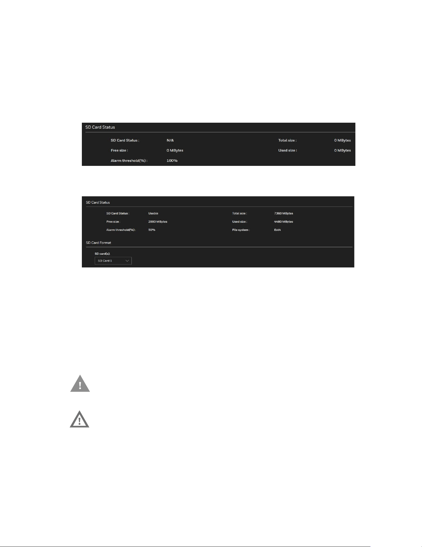
48
Honeywell 35 Series IP Cameras User Guide
SD Card Status
This tab shows the status and reserved space of your SD card. Up to two SD cards are
supported. Redundant storage mode can be enabled with two SD cards.
Remember to format the SD card when using it for the first time, see SD Card Format on
page 48.
Figure 35 No SD Card
Figure 36 SD Card Onboard
SD Card Format
To format the SD Card, select the SD card and click FORMAT.
Insert/detach SD Card
The following instructions apply while inserting and detaching the SD card from the
camera.
Caution: Do not detach the SD card while the formatting is going on.
Warning: Check if any recording such as continuous recording is
running and disable the event or recording rule before
detaching the SD card. The SD card has unformatted
status after reinserting into the camera if the
recording was on while you removed it from the
camera.
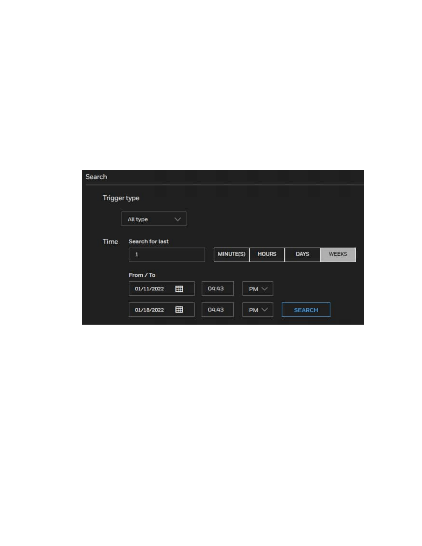
49
Honeywell 35 Series IP Cameras User Guide
Content Management
Go to Setup > Storage Setup > Content Management.
This section describes how to manage the content of recorded videos on the camera.
Here you can search and view the records and view the searched results.
Searching and Viewing the Records
This tab allows the user to set up search criteria for recorded data. If you do not select
any criteria and click SEARCH, all recorded data will be listed in the Search Results tab.
• Trigger type: Select one or more triggers from Backup, System boot, Alarm input,
Motion, Network failure, Recording notification, Periodically, Tampering detection,
and VADP.
• Time: Manually enter the time range you want to search for contents created at a
specific point in time.
Click SEARCH and the recorded data corresponding to the search criteria will be listed
in Search Results tab.
Search Results
To sort the search results, click each column header.
Download: Click on a search result and click DOWNLOAD, and a file download window
will pop up for you to save the file. You can play the video clip by VLC player.
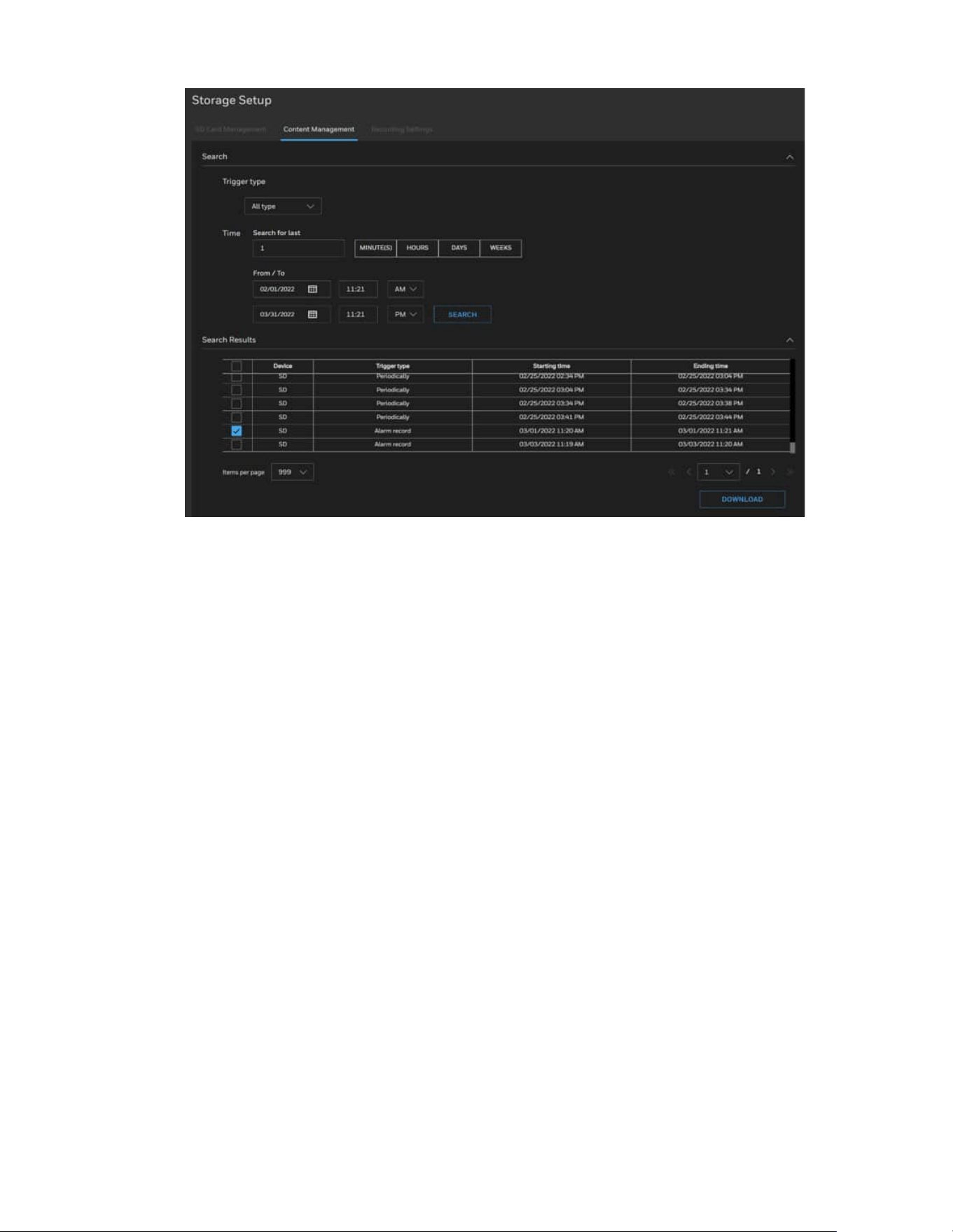
50
Honeywell 35 Series IP Cameras User Guide
Note:
The alarm records sorted in Trigger type are alarm type recording, not periodically
recording.
It includes
Motion alarm, I/O alarm, Intrusion alarm, Multi loiter alarm, Smart
motion alarm, Camera tamper alarm, Personnel count threshold alarm.
Recording Settings
Go to Setup > Storage Setup > Recording Settings.
This section describes how to configure the recording settings for the camera.
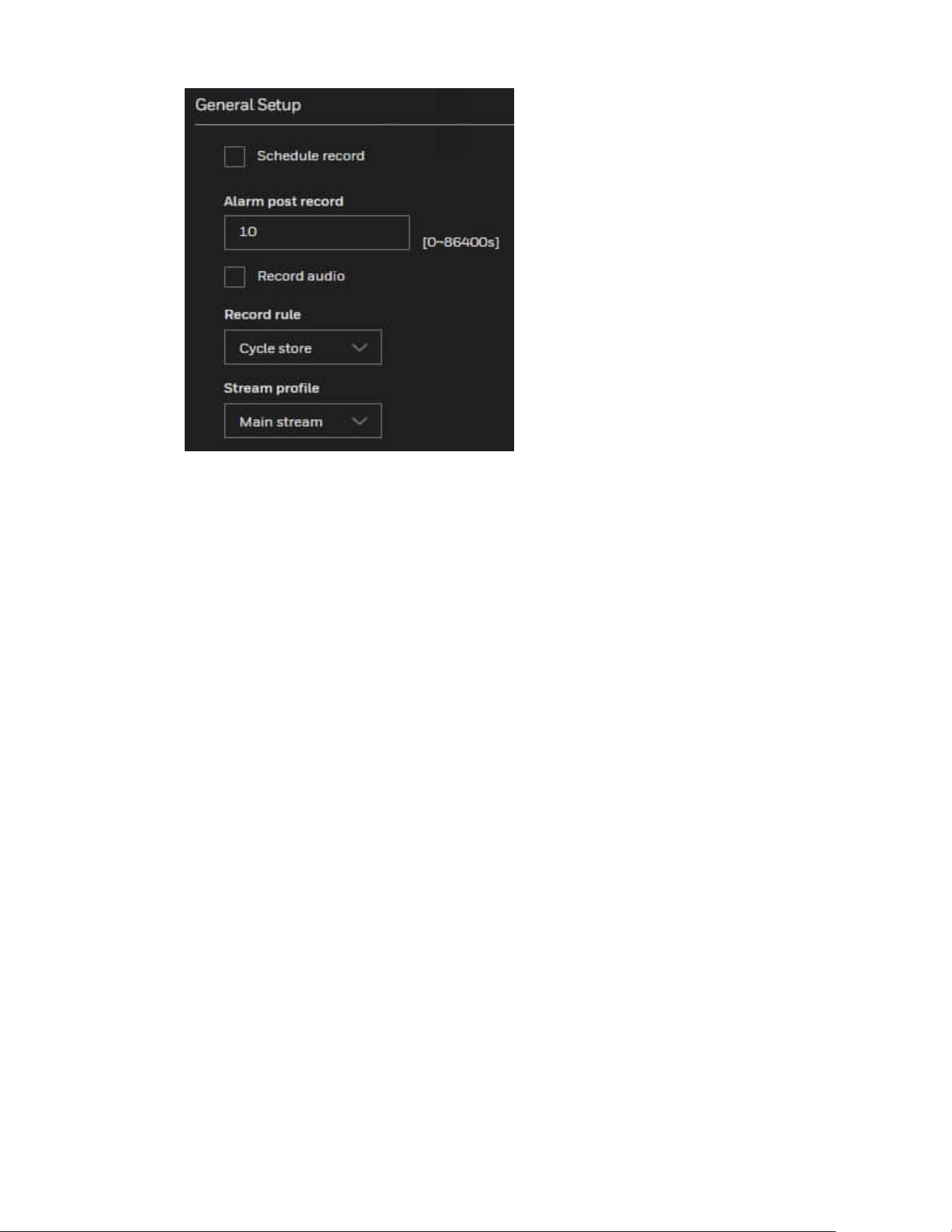
51
Honeywell 35 Series IP Cameras User Guide
Schedule record: Enables schedule record that you can configure the time policy.
Alarm post record: Recording duration (in seconds) after an alarm is generated.
Record audio: Indicates whether to record audios together with videos.
Record rule: Rule for saving recordings. The options are as follows:
Cycle Store: Saves recordings in cycles.
Save Days: Duration (in days) for saving a recording. The duration can be a maximum of
99999 days.
The value 0 indicates that recordings are not overwritten.
Stream profile: Select from the dropdown list: Main stream, Sub stream, Third stream.
Note:
Above settings will be applied to all video recording behaviors globally.
Defence time: Left-click or drag the mouse to select any time within 0:00-24:00 from
Monday to Sunday.
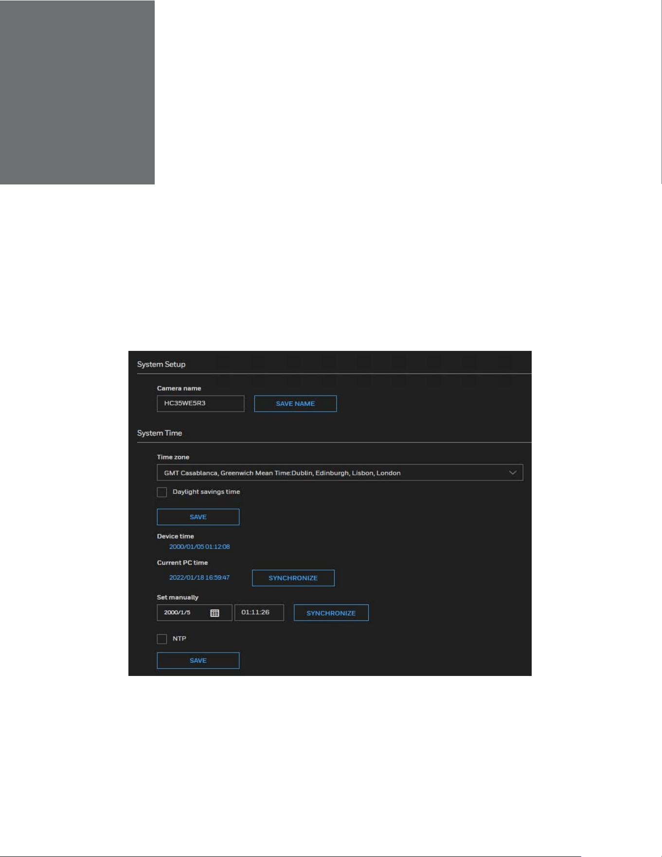
CHAPTER
52
Honeywell 35 Series IP Cameras User Guide
9 CONFIGURE SYSTEM SETTINGS
Configuring System General Settings
Go to Setup > System Setup > General Settings.
This section explains how to configure the basic settings for the camera, such as the
host name and system time.
Figure 37 System General Settings
Camera Name: Enter a name for the camera. The text will be displayed at the top of the
main page.
Time zone: Select the appropriate time zone from the dropdown list. If you want to
upload Daylight Savings Time rules, see Configuring Maintenance Settings on page 53.
Daylight savings time: Check the checkbox to enable Daylight savings time and specify
the DST start time and end time.
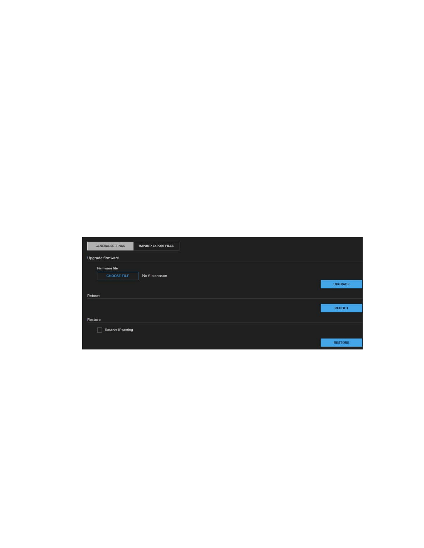
53
Honeywell 35 Series IP Cameras User Guide
When the DST start time arrives, the device time automatically goes forward one
hour.
When the DST end time arrives, the device time automatically goes backward one
hour.
Device time: Device display time.
Current PC time: Time on the current PC.
Set manually: Enables you to manually set the device time.
NTP: IP address or domain name of the NTP server. Check the checkbox to enable NTP.
NTP server addr: The NTP server IP.
NTP Port: Port number of the NTP server.
Check the time interval( at least 10 s): Set time interval to check if the device time
synchronizes with the NTP server time.
Configuring Maintenance Settings
Go to Setup > System Setup > Maintenance.
This chapter describes how to restore the camera to factory default, upgrade firmware
version, etc.
Upgrading Firmware
On this page, you can upgrade the firmware of the camera. It takes a few minutes to
complete the process.
Note:
•
Do not power off the camera during the upgrade.
•
If an SD card is used in your camera, backup your SD card contents if necessary
before the upgrade.
Follow the steps below to upgrade the firmware:
1. Click CHOOSE FILE and locate the firmware file.
2. Click UPGRADE. The camera starts to upgrade and will reboot automatically when

54
Honeywell 35 Series IP Cameras User Guide
the upgrade completes.
• If an SD card is used in your camera, it will be formatted automatically after the
upgrade. The formatting may take 5 to 20 minutes.
• After the SD card is formatted, it will be encrypted and its content cannot be read on
other cameras.
• If you want to use the SD card in another camera, format the SD card in another
camera first. For how to format the SD card, see SD Card Format on page 48.
• A new SD card inserted to camera will also be formatted automatically after the
camera is upgraded.
• If the upgrade is successful, the “Reboot system now!! This connection will close”
message will be displayed. After that, re-access the camera. If an SD card is inserted
to the camera, wait for the SD card formatting to complete.
Rebooting the Camera
On this page, you can reboot the camera. It takes about one minute to complete. After it
is completed, the live video page will be displayed in your browser.
If the connection fails after rebooting, manually enter the IP address of the camera in
the address field to resume the connection.
Restoring the Camera
Restore the camera to factory default settings.
Network Setup: Check to retain the Network Type settings (see Configuring Network
General Settings on page 27).
Daylight Saving Time: Check to retain the Daylight Saving Time settings (see
Importing/Exporting Files on page 54).
Focus position: Check to retain the lens focus position using the previously saved
position parameters.
If none of the options is selected, all settings will be restored to factory default. Click
RESTORE and the camera will be rebooted.
After it is completed, the live video page will be displayed in your browser.
If the connection fails after rebooting, manually enter the IP address of the camera in
the address field to resume the connection.
Importing/Exporting Files
Export / Upload daylight saving time rules, custom language file, configuration file, and
server status report.
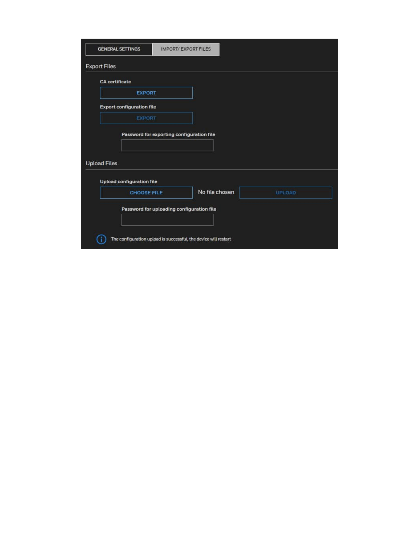
55
Honeywell 35 Series IP Cameras User Guide
Export CA Certificate
The camera uses HTTPS, a secure communication protocol that verifies the identities of
visited websites and servers and encrypts data exchanged between the client and the
server. When you log in to the camera’s web client for the first time, some browsers may
display a warning that the connection is not private/secure. To access the web client,
you must install a Honeywell-signed security certificate.
1. Click Export to save the root certificate (ca.crt) on your local computer.
2. Go to the directory where you saved the certificate and double-click the certificate.
The Certificate window opens.
3. In the Certificate window, on the General tab, click Install Certificate to open the
Certificate Import Wizard.
4. Click Next to continue.
5. Click Place all certificates in the following store, click Browse, click Trusted Root
Certification Authorities, and then click OK.
6. Click Next, and then click Finish to close the Certificate Import Wizard. A
confirmation dialog box appears with the message “The import was successful.”
7. Click OK, and then click OK to close the Certificate window. And now your browser
will not display a warning that the connection is not private/ secure.
Please ensure to install the certificate to ensure a secure communication with the
camera and to avoid delays in the web page navigation.

56
Honeywell 35 Series IP Cameras User Guide
Export Configuration File
Click EXPORT to export all parameters for the camera and user-defined scripts.
Note:
User needs to specify the password before exporting the configuration file.
Upload Configuration File
Follow the steps below to upload a configuration file:
1. Enter the password for uploading the configuration file. The password must be the
same with the password of the configuration file you set for exporting, or the
uploading will be failed. For example, if you set the password A for the
configuration file A and you set the password B for the configuration file B. When
you want to upload the configuration file B, you must use the password B.
2. Click CHOOSE FILE to locate the configuration file and then click UPLOAD to
upload the configuration file.
The model and firmware version of the device should be the same as the configuration
file. If you have set up a fixed IP or other special settings for your device, it is not
suggested to update a configuration file.
If the power is disconnected during firmware upgrade or if there is unknown reason
causing abnormal LED status, and a Restore cannot recover normal working condition,
you can perform the following steps to activate the camera with its backup firmware:
a) Press and hold down the reset button for at least one minute.
b) Power on the camera until the Red LED blinks rapidly.
c) After boot up, the firmware should return to the previous version before the
camera hanged. (The procedure should take 5 to 10 minutes, longer than the
normal boot-up process). When this process is completed, the LED status
should return to normal.
Configuring User Accounts Settings
Go to Setup > System Setup > User Accounts.
This section describes how to create multiple accounts and grant privileges to these
accounts.
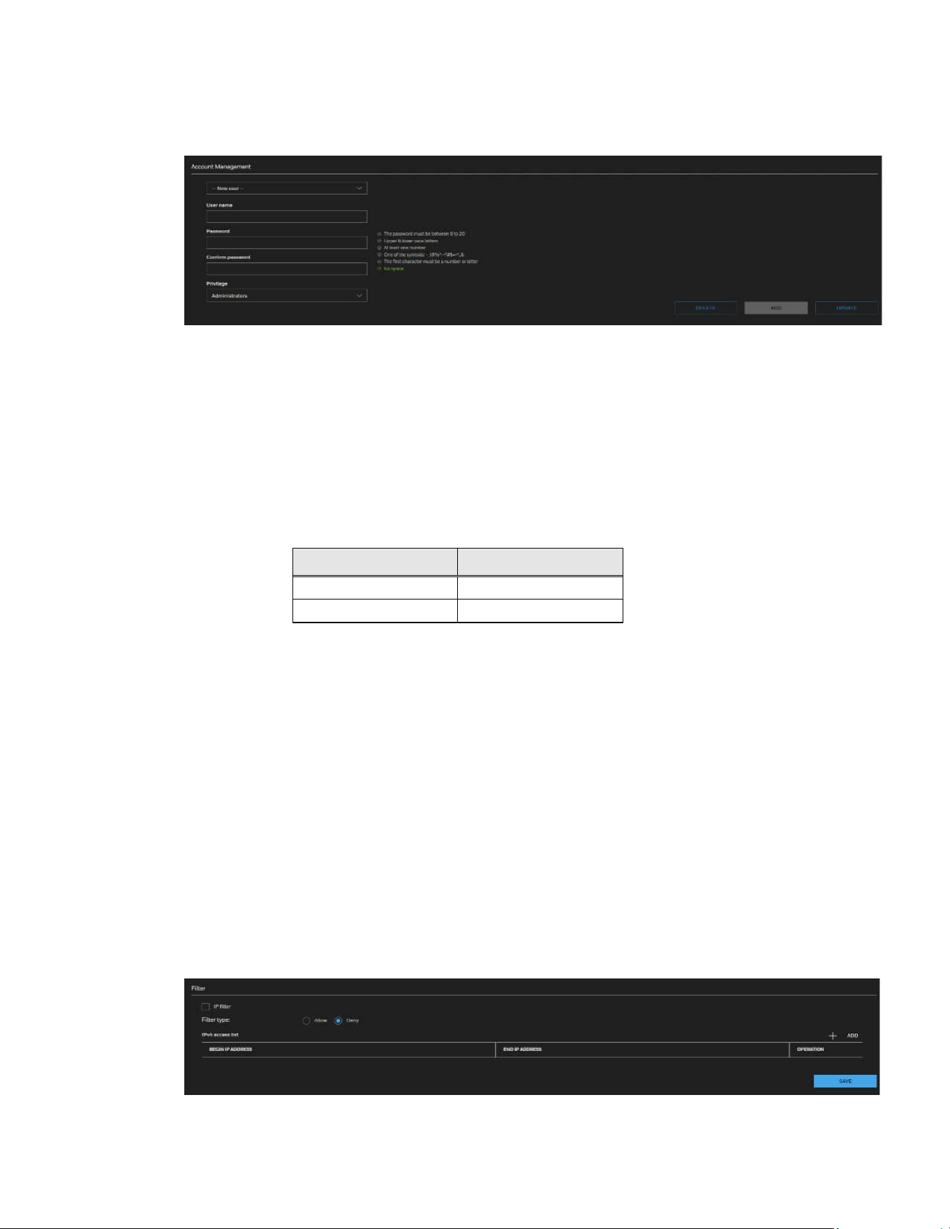
57
Honeywell 35 Series IP Cameras User Guide
Account Management
The administrator account name is “admin”, which is permanent and cannot be deleted.
The administrator can create up to 20 user accounts. To create a new user:
1. Select New user from the dropdown list.
2. Enter the new user’s name and password and confirm the password. Some, but
not all special ASCII characters are supported. You can use “!?@#$%=+*-_:,.&^~” in
the password combination.
3. Select the privilege level for the new user account. Click ADD to enable the setting.
The privilege levels are listed below:
Role
Privilege
Administrator
Full control
Viewer
Live, Language
Access rights are sorted by user privilege (Administrator, Operator, and Viewer). Only
administrators can access the Configuration page. Viewers can only access the main
page for live viewing.
To change a user’s access rights or delete user accounts:
1. Select an existing account.
2. Make necessary changes and click UPDATE to enable the setting or click DELETE
to delete the account.
Configuring Access List Settings
Go to Setup > System Setup > Access List.
This section describes how to control access permission by verifying the client PC’s IP
address.

58
Honeywell 35 Series IP Cameras User Guide
IP filter: Check this item and click SAVE to enable the IP filtering function.
Filter type: Select Allow or Deny as the filter type. If you choose Allow Type, only those
clients whose IP addresses are on the Access List below can access the camera, and the
others cannot. On the contrary, if you choose Deny Type, those clients whose IP
addresses are on the Access List below will not be allowed to access the camera, and the
others can.
Click ADD and you can add a filter address.
Note:
•
The IPv6 access list column will not be displayed unless you enable IPv6 on the
Network page. For more information about IPv6 Settings, see Enable IPv6 on page
49.
•
The Range rule only applies to IPv4 addresses.
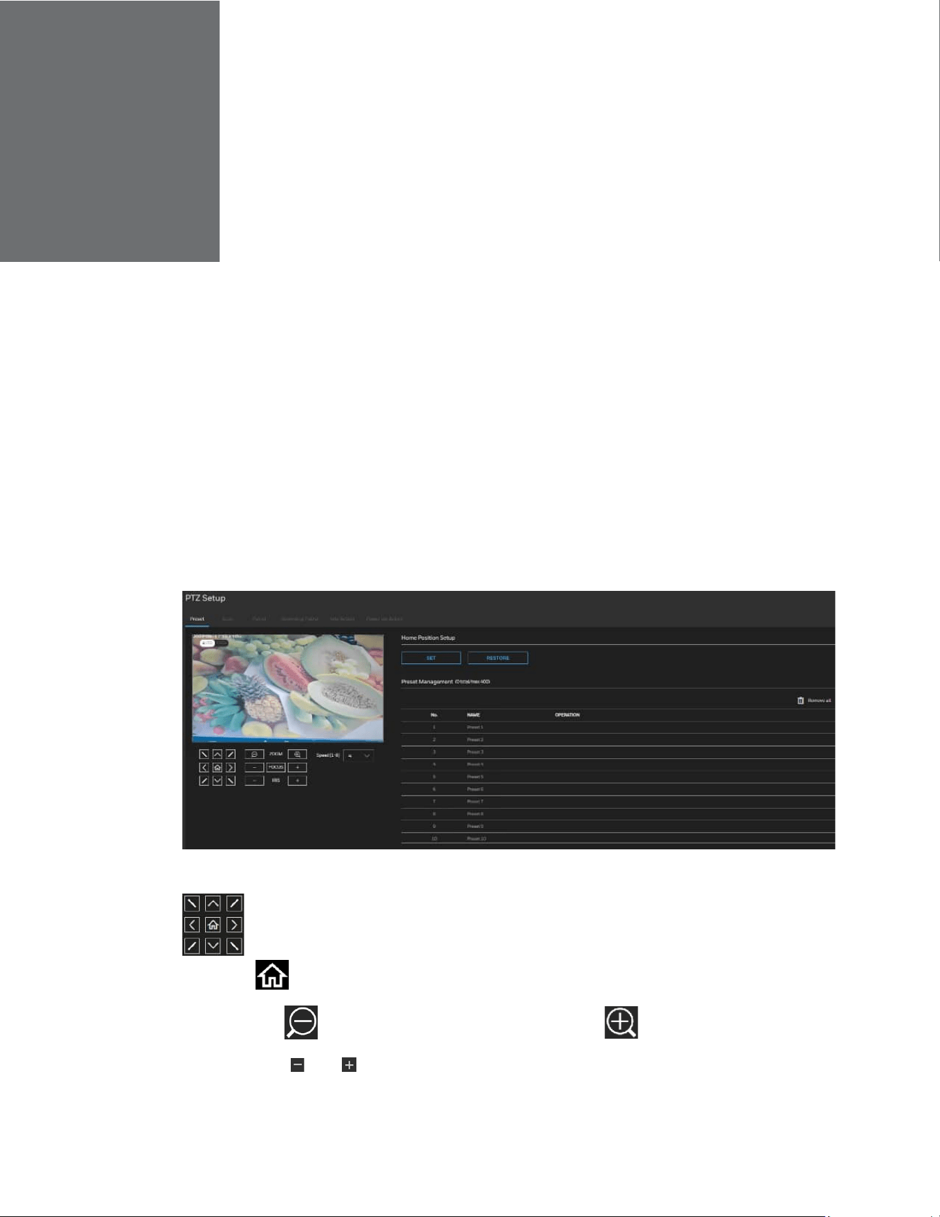
CHAPTER
59
Honeywell 35 Series IP Cameras User Guide
10 CONFIGURING PTZ SETTINGS
This section describes how to control the camera’s Pan/Tilt/Zoom operation.
Note:
The functions in this section are applicable for PTZ cameras only.
Preset
Go to Setup PTZ Setup Preset.
Figure 38 Preset Settings
: Click the buttons to move the video image up/right/down/left/45-degree tilt
and click to return to the home location.
ZOOM: Click to zoom out the video image or click to zoom in the video image.
FOCUS: Click and to adjust the Focus setting.
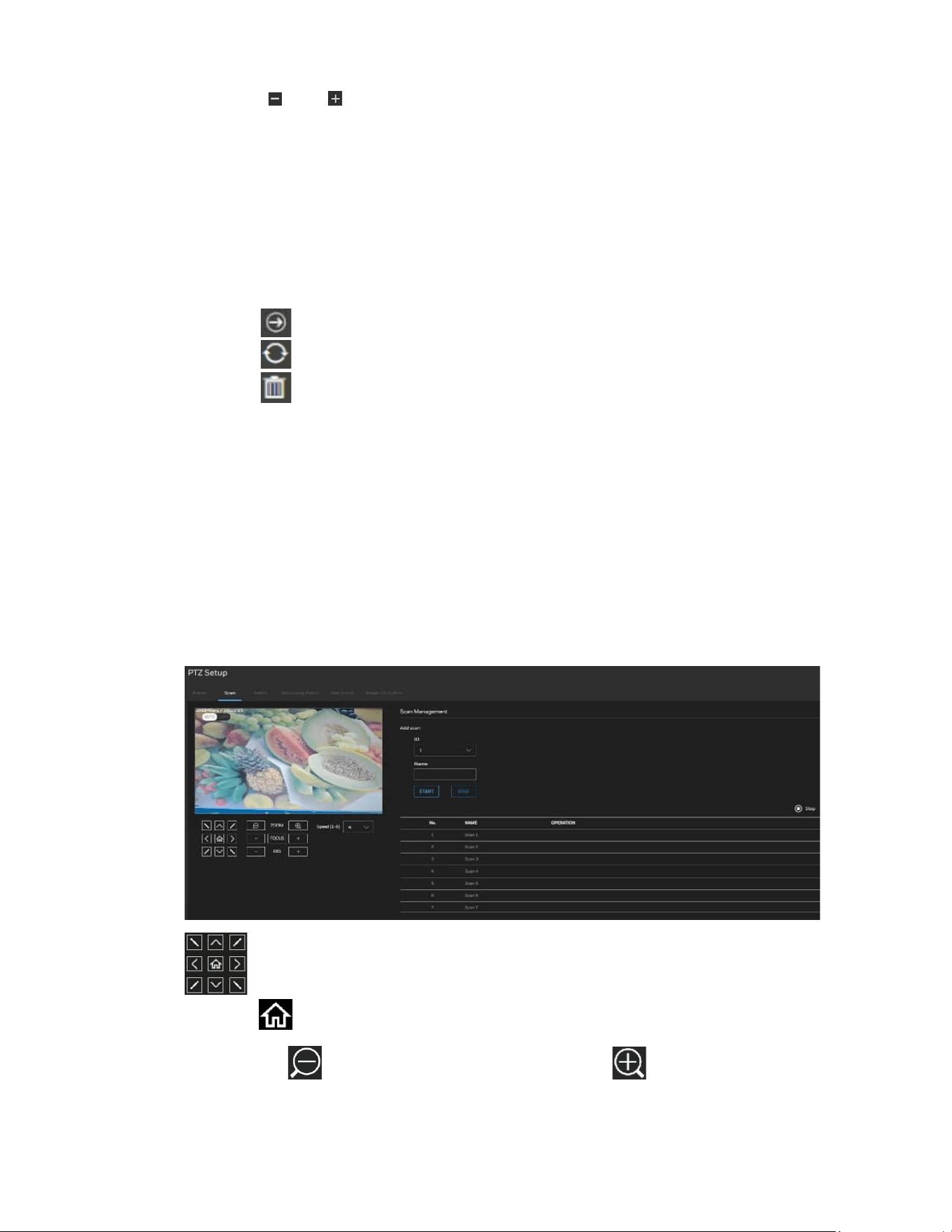
60
Honeywell 35 Series IP Cameras User Guide
IRIS: Click and to adjust the IRIS setting.
Speed [1-8]: Select the movement speed for camera view. The speed range is 1 to 8 and
the default setting is 5.
Home Position Setup
SET: Click to set the current position as the home location.
RESTORE: Click to restore the home position to default.
Preset Management
Click Remove all to delete all the preset list.
Click to go to this preset.
Click to replace this preset with current position.
Click to remove the preset.
Note:
Preset point 80~115 are reserved for special presets. And calling special preset 103
will run wiper once.
Scan Management
Go to Setup PTZ Setup Scan.
Figure 39 Scan Settings
: Click the buttons to move the video image up/right/down/left/45-degree tilt
and click to return to the home location.
ZOOM: Click to zoom out the video image or click to zoom in the video image.
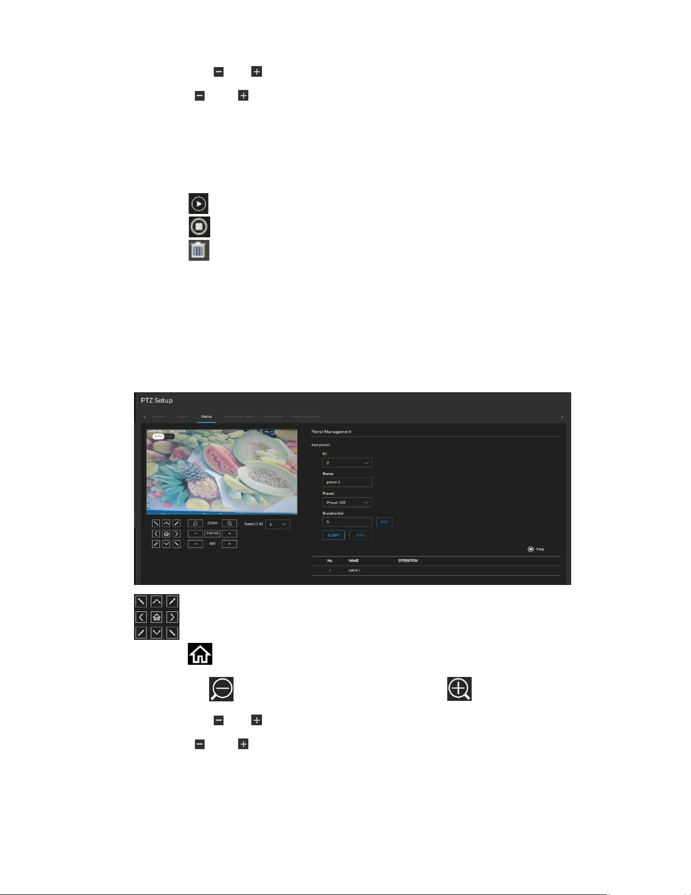
61
Honeywell 35 Series IP Cameras User Guide
FOCUS: Click and to adjust the Focus setting.
IRIS: Click and to adjust the IRIS setting.
Speed [1-8]: Select the movement speed for camera view. The speed range is 1 to 8 and
the default setting is 5.
Scan Management
Add scan: Set the scan ID and name. Click START to start record. Click END to end
record.
Click to start this scan.
Click to stop the scan setting.
Click to remove the scan.
Patrol
Go to Setup PTZ Setup Patrol.
Figure 40 Patrol Settings
: Click the buttons to move the video image up/right/down/left/45-degree tilt
and click to return to the home location.
ZOOM: Click to zoom out the video image, or click to zoom in the video image.
FOCUS: Click and to adjust the Focus setting.
IRIS: Click and to adjust the IRIS setting.
Speed [1-8]: Select the movement speed for camera view. The speed range is 1 to 8 and
the default setting is 5.
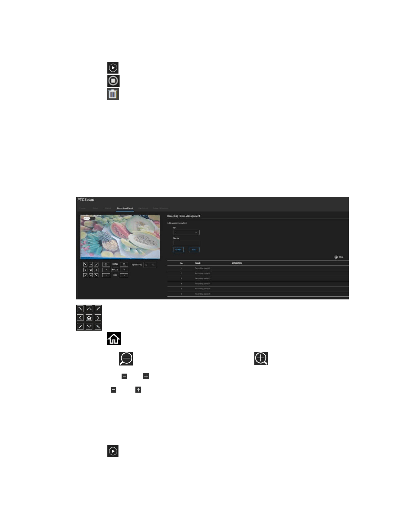
62
Honeywell 35 Series IP Cameras User Guide
Patrol Management
Add patrol: Set the patrol ID/Name/Preset/Duration(s). Click START to start record.
Click END to end record.
Click review your recorded patrol.
Click to stop the patrol review.
Click to remove the patrol.
This patrol list displays the configured patrols. Note that only one patrol can be applied
at a time.
Recording Patrol
Go to Setup PTZ Setup Recording Patrol.
Figure 41 Recording Patrol
: Click the buttons to move the video image up/right/down/left/45-degree tilt
and click to return to the home location.
ZOOM: Click to zoom out the video image, or click to zoom in the video image.
FOCUS: Click and to adjust the Focus setting.
IRIS: Click and to adjust the IRIS setting.
Speed [1-8]: Select the movement speed for camera view. The speed range is 1 to 8 and
the default setting is 5.
Recording Patrol Management
Add recording patrol: Set the recording patrol ID and Name. Click START to start record.
Click END to end record.
Click review your recording
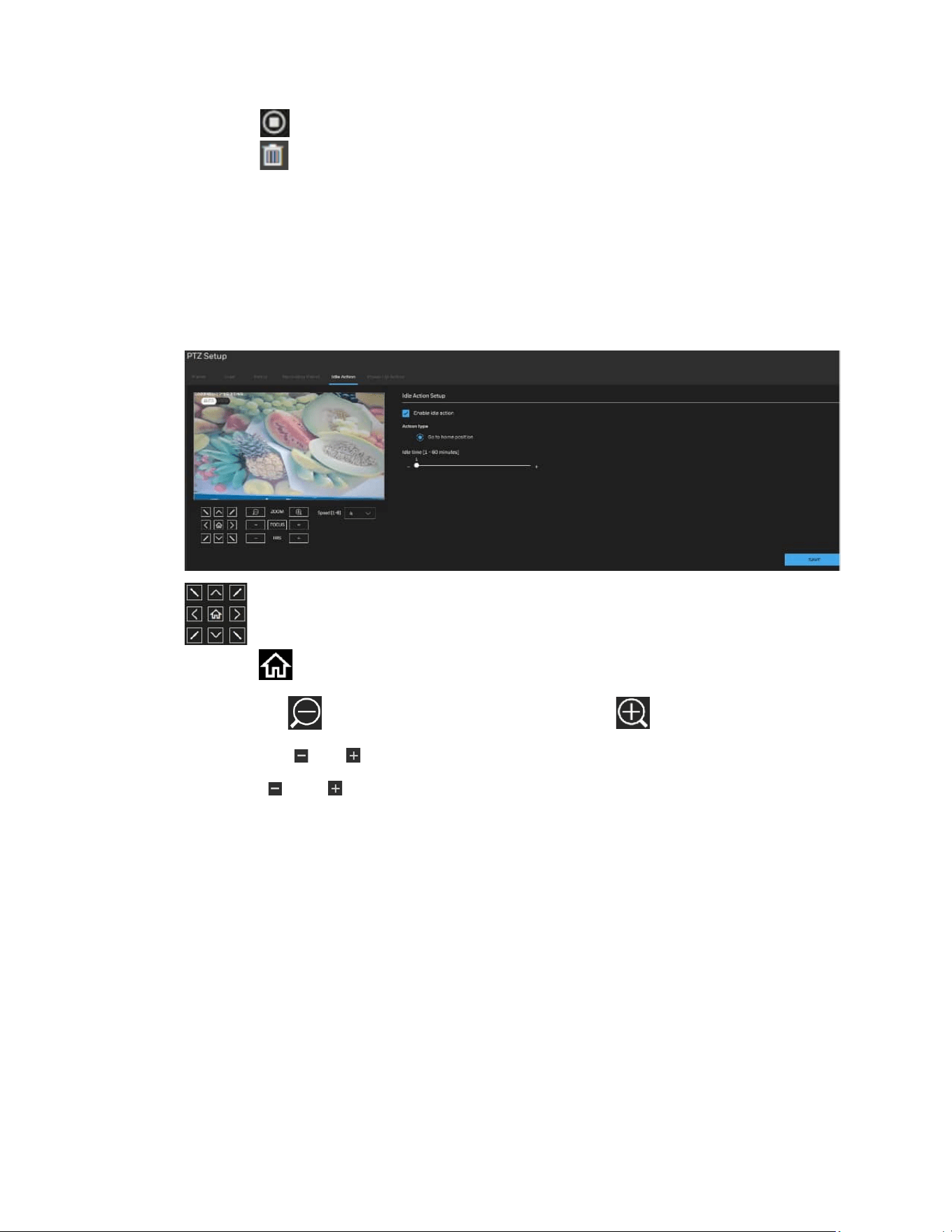
63
Honeywell 35 Series IP Cameras User Guide
patrol.
Click to stop the recording patrol review.
Click to remove the recording patrol.
Idle Action
Go to Setup PTZ Setup Idle Action.
Figure 42 Idle Action
: Click the buttons to move the video image up/right/down/left/45-degree tilt
and click to return to the home location.
ZOOM: Click to zoom out the video image, or click to zoom in the video image.
FOCUS: Click and to adjust the Focus setting.
IRIS: Click and to adjust the IRIS setting.
Speed [1-8]: Select the movement speed for camera view. The speed range is 1 to 8 and
the default setting is 5.
Check the checkbox to enable idle action. Set the idle time. Click SAVE.
Power Up Action
Go to Setup PTZ Setup Power Up Action.
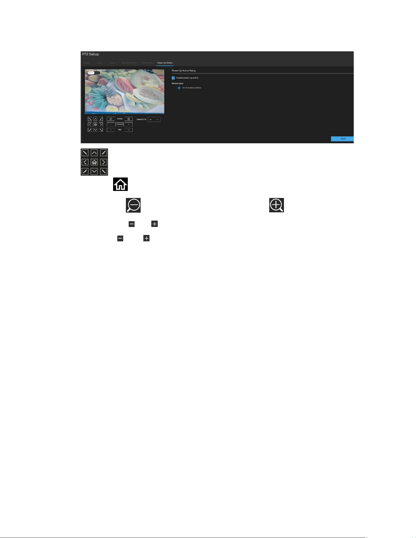
64
Honeywell 35 Series IP Cameras User Guide
Figure 43 Power Up Action
: Click the buttons to move the video image up/right/down/left/45-degree tilt
and click to return to the home location.
ZOOM: Click to zoom out the video image, or click to zoom in the video image.
FOCUS: Click and to adjust the Focus setting.
IRIS: Click and to adjust the IRIS setting.
Speed [1-8]: Select the movement speed for camera view. The speed range is 1 to 8 and
the default setting is 5.
Check the checkbox to enable power up action. Click SAVE.
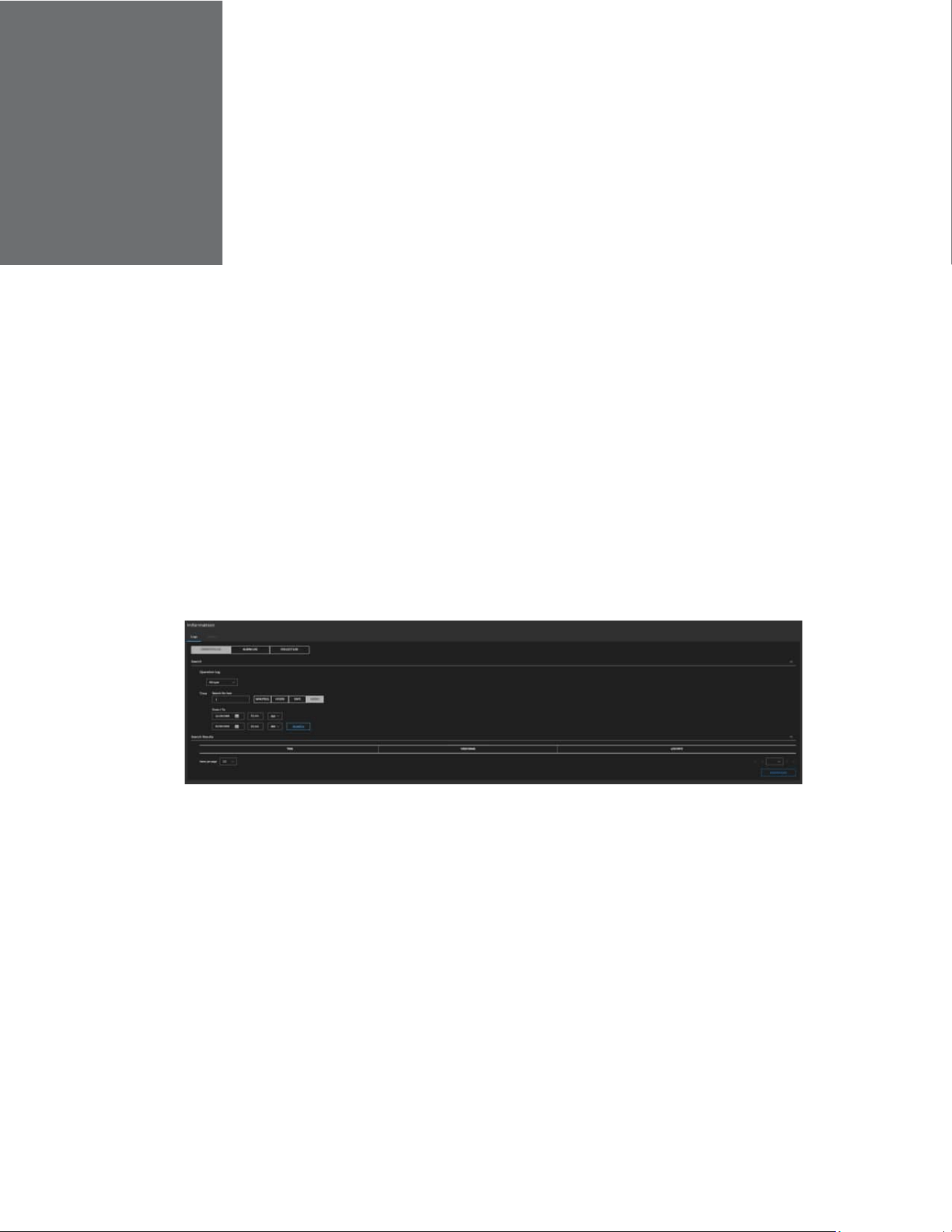
CHAPTER
65
Honeywell 35 Series IP Cameras User Guide
11 VIEWING SYSTEM INFORMATION
Log
Go to Setup > Information > Logs.
Operation Log
Operation logs record user operations and scheduled task commands during the
running of the device. Operation logs can be classified into the following types:
permission management, system maintenance, device configuration, recording
operation, video control, and real-time video.
1. Select the type of operation logs to be queried from the drop-down list box.
2. Set the start time and end time as required.
3. Click SEARCH.
The operation logs are displayed.
4. Click Download on the right of the page to download the operation logs.
Alarm Log
An alarm log records information about an alarm generated on a device, including the
security, disk, and recording alarms.
1. Select the type of alarm logs to be queried from the drop-down list box.

66
Honeywell 35 Series IP Cameras User Guide
2. Set the start time and end time as required.
3. Click SEARCH.
4. The alarm logs are displayed.
5. Click Download on the right of the page to download the operation logs.
Collect Log
You can collect logs about a device, which help you analyze and solve possible problems
occurring on the device with one click.
1. Click COLLECT, the download page is displayed.
2. Select the path to save the logs.
Version
Go to Setup > Information > Version.
On the Version page, you can view the software version.

CHAPTER
67
Honeywell 35 Series IP Cameras User Guide
12 TROUBLE SHOOTING
Troubleshooting for Common Issues
Refer to the following guidelines to troubleshoot any performance issues. If you require
additional assistance, contact Honeywell Technical Support (see back cover for contact
information).
Table 5 Troubleshooting for Common Issues
Issues Solutions
Power supply is unstable.
Use of a UPS power supply is strongly recommended.
Camera webpage has abnormal
display.
Clear the cache of browser.
• If the pc screen width is 1366px, it is recommended to
zoom the browser to 80%.
• If the pc screen width is 1920px, it is recommended to
zoom the browser to 100%.
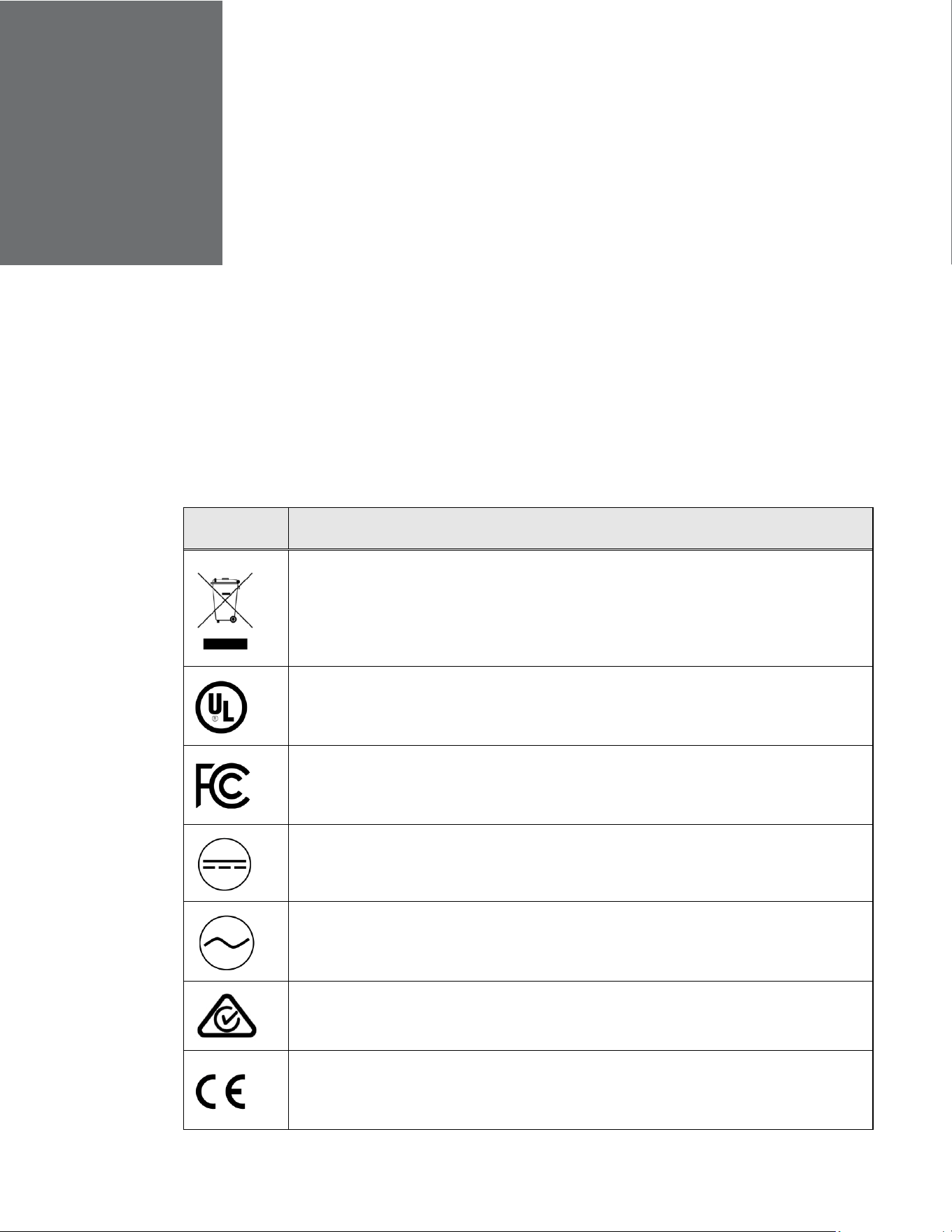
CHAPTER
68
Honeywell 35 Series IP Cameras User Guide
13 APPENDIX
List of Symbols
The following is a list of symbols that may appear on the camera:
Table 6 List of Symbols
Symbol Explanation
The WEEE symbol.
This symbol indicates that when the end-user wishes to discard this product, it must be
sent to separate collection facilities for recovery and recycling. By separating this
product from other household-type waste, the volume of waste sent to incinerators or
landfills will be reduced, and thus natural resources will be conserved.
The UL compliance logo.
This logo indicates that the product has been tested and is listed by UL (formerly
Underwriters Laboratories).
The FCC compliance logo.
This logo indicates that the product conforms to Federal Communications Commission
compliance standards.
The direct current symbol.
This symbol indicates that the power input/output for the product is direct current.
The alternating current symbol.
This symbol indicates that the power input/output for the product is alternating current.
The RCM compliance logo.
This logo indicates that the product conforms with Australian RCM guidelines.
The CE compliance logo.
This logo indicates that the product conforms to the relevant guidelines/standards for
the European Union harmonization legislation.
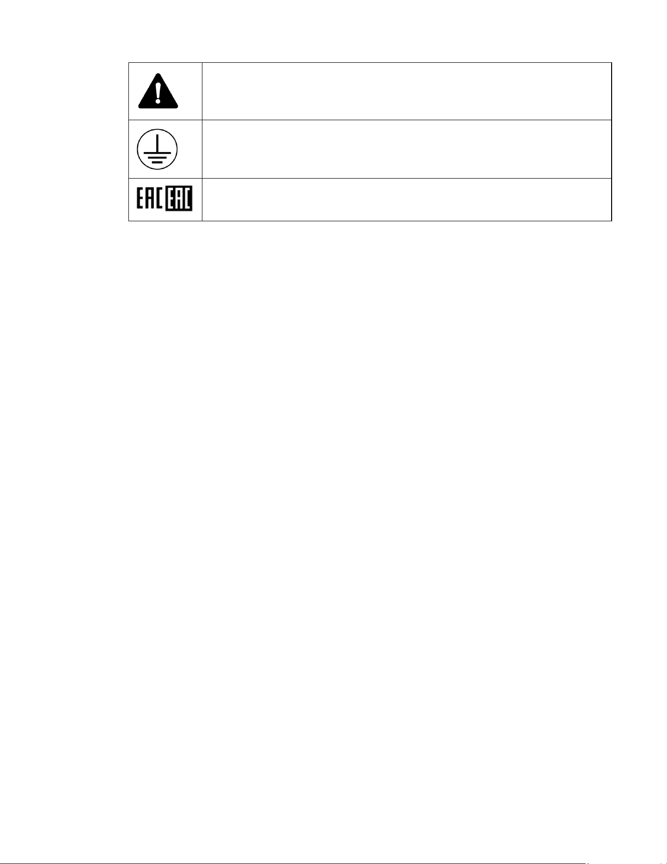
69
Honeywell 35 Series IP Cameras User Guide
The caution symbol.
This symbol indicates important information.
The protective earth (ground) symbol.
This symbol indicates that the marked terminal is intended for connection to the
protective earth/grounding conductor.
Eurasian Conformity (EAC) RoHS

Honeywell Building Technologies – Security Americas (Head Office)
Honeywell Commercial Security
715 Peachtree St. NE
Atlanta, GA 30308
Tel: +1 800 323 4576
Honeywell Building Technologies – Security Mexico
Mexico: Av. Santa Fe 94, Torre A, Piso 1, Col. Zedec,
CP 012010, CDMX, México.
Colombia: Edificio Punto 99, Carrera 11a.
98-50, Piso 7, Bogota, Colombia.
Tel: 01.800.083.59.25
Honeywell Building Technologies – Security Middle East/N. Africa
Emaar Business Park, Building No. 2, Sheikh Zayed Road
P.O. Box 232362
Dubai, United Arab Emirates
security_meta@honeywell.com
Tel: +971 4 450 5800
Honeywell Building Technologies – Security Europe/South Africa
140 Waterside Road, Hamilton Industrial Park
Leicester, LE5 1TN, United Kingdom
Tel: +44 (0) 1928 378005
Honeywell Building Technologies – Security Northern Europe
Stationsplein Z-W 961, 1117 CE Schiphol-Oost, Netherlands
Tel: +31 (0) 299 410 200
Honeywell Building Technologies – Security
Deutschland
Johannes-Mauthe-Straße 14
D-72458 Albstadt
Germany
Tel: +49 (0) 7431 801-0
Honeywell Building Technologies – Security France
Immeuble Lavoisier
Parc de Haute Technologie
3-7 rue Georges Besse
92160 Antony, France
Tel: +33 (0) 1 40 96 20 50
Honeywell Building Technologies – Security Italia SpA
Via Achille Grandi 22,
20097 San Donato Milanese (MI), Italy
Honeywell Building Technologies – Security España
Josefa Valcárcel, 24
28027 – Madrid, España
Tel.: +34 902 667 800
Honeywell Building Technologies – Security Россия и
СНГ
121059 Moscow,
UI, Kiev 7
Russia
Tel: +7 (495) 797-93-71
Honeywell Building Technologies – Security Asia
Pacific
Building #1, 555 Huanke Road,
Zhang Jiang Hi-Tech Park Pudong New Area,
Shanghai, 201203, China
Tel: 400 840 2233
Honeywell Building Technologies – Security and Fire
(ASEAN)
Honeywell International Sdn Bhd
Level 25, UOA Corp Tower, Lobby B
Avenue 10, The Vertical, Bangsar South City
59200, Kuala Lumpur, Malaysia
Email: buildings.asean@honeywell.com
Technical support (Small & Medium Business):
Vietnam: +84 4 4458 3369
Thailand: +66 2 0182439 Indonesia: +62 21 2188 9000
Malaysia: +60 3 7624 1530
Singapore: +65 3158 6830
Philippines: +63 2 231 3380
Honeywell Home and Building Technologies (India)
HBT India Buildings
Unitech Trade Centre, 5th Floor,
Sector – 43, Block C, Sushant Lok Phase – 1,
Gurgaon – 122002, Haryana, India
Email: HBT-IndiaBuildings@honeywell.com
Toll Free Number: 000 800 050 2167
Tel: +91 124 4975000
Honeywell Building Technologies – Security and Fire
(Korea)
Honeywell Co., Ltd. (Korea)
5F SangAm IT Tower,
434, Worldcup Buk-ro, Mapo-gu,
Seoul 03922, Korea
Email: info.security@honeywell.com
Customer support: HSG-CS-[email protected]; +82 1522-8779
Tel: +82-2-799-6114
Honeywell Building Technologies – Security & Fire (Pacific)
Honeywell Ltd
9 Columbia Way
BAULKHAM HILLS NSW 2153
Email: hsf.comms.pacific@Honeywell.com
Technical support:
Australia: 1300 220 345
New Zealand: +64 9 623 5050
https://buildings.honeywell.com/security
+1 800 323 4576 (North America only)
Document 800-26904 Rev B – 05/2022