
4-549-307-18(1)
Solid-State Memory
Camcorder
PXW-X200
© 2014 Sony Corporation
Operating Instructions
Before operating the unit, please read this manual thoroughly
and retain it for future reference.

Table of Contents
2
Overview
Part Identification ..................................................................... 8
Camcorder ...................................................................... 8
IR Remote Commander (Supplied) .............................. 13
On-Screen Indications ............................................................ 14
Direct Menu Operation ................................................ 16
Preparations
Power Supply ........................................................................... 18
Using a Battery Pack .................................................... 18
Using AC Power (DC IN Power) ................................. 19
Turning the Power On/Off ........................................... 19
Setting the Clock ..................................................................... 20
Adjusting the LCD Monitor and Viewfinder ....................... 20
Adjusting the LCD Monitor ......................................... 20
Adjusting the Viewfinder ............................................. 20
Using the IR Remote Commander ........................................ 21
Using SxS Memory Cards ...................................................... 22
About SxS Memory Cards ........................................... 22
Inserting/Removing an SxS Memory Card .................. 23
Switching Between SxS Memory Cards ...................... 23
Formatting an SxS Memory Card ................................ 23
Checking the Remaining Time Available for
Recording ............................................................... 24
Restoring an SxS Memory Card .................................. 24
Using Other Media .................................................................. 25
XQD Memory Cards .................................................... 25
SD Cards ...................................................................... 25
USB Flash Drives ......................................................... 26
Recording
Basic Operation Procedure .................................................... 28
Changing Basic Settings ......................................................... 30
Video Formats .............................................................. 30
ND Filter ...................................................................... 31
White Balance .............................................................. 31
Table of Contents

Table of Contents
3
Markers/Zebra Patterns ................................................ 33
Gain .............................................................................. 33
Electronic Shutter ......................................................... 33
Iris ................................................................................ 34
Zoom ............................................................................ 34
Focus ............................................................................ 35
Steady Shot ................................................................... 36
Flickers ......................................................................... 36
Time Data ..................................................................... 36
Recording Audio Signals ........................................................ 37
Using the Built-in Stereo Microphones ........................ 37
Using External Inputs ................................................... 37
Using an External Microphone .................................... 37
Adjusting the Audio Recording Levels ........................ 38
Monitoring the Audio ................................................... 38
Useful Functions ...................................................................... 39
Color Bars/Reference Tone .......................................... 39
Shot Marks ................................................................... 39
OK/NG/KP Flags (UDF and exFAT) .......................... 39
OK Mark (FAT HD Mode Only) ................................. 39
Rec Review .................................................................. 40
Assignable Buttons ....................................................... 40
Interval Recording ........................................................ 40
Frame Recording .......................................................... 41
Clip Continuous Recording (UDF and exFAT) ........... 42
Picture Cache Recording: Retroactively Record .......... 42
Slow & Quick Motion .................................................. 43
Simultaneous Recording in the 2 slots ......................... 44
Freeze Mix: Image Alignment ..................................... 45
Automatic Adjustment of Flange Focal Length ........... 45
Picture Profiles ............................................................. 46
Deleting Clips ............................................................... 54
Storing/Retrieving the Setting Data ............................. 54
Planning Metadata ........................................................ 56
Obtaining Location Information (GPS) ....................... 58
Proxy Recording ..................................................................... 60
Usable SD Cards .......................................................... 60
Formatting an SD Card ................................................ 60
Checking the Remaining Time ..................................... 60
Performing Proxy Recording ....................................... 60
About the Automatic Upload of the Proxy File ........... 61
Changing the Proxy Recording Setting ........................ 61
About the Recorded File .............................................. 61
Storage Destination of the Recorded File .................... 61
About the File Name .................................................... 61
Recording of the proxy file’s still images .................... 61

Table of Contents
4
Connecting to Other Device via Wireless LAN .................... 62
Attaching the wireless LAN module (IFU-WLM3) ..... 63
Attaching the wireless LAN module (CBK-WA02) .... 63
Connecting with the Wireless LAN Access Point
Mode ...................................................................... 63
Connecting with the Wireless LAN Station Mode ...... 65
Connecting to the Internet ..................................................... 67
Connecting with a modem ........................................... 67
Connecting with the wireless LAN Wi-Fi station
mode ....................................................................... 67
Connecting to the Internet with a LAN cable .............. 70
List of functions for network connections ................... 71
Required devices for network connections .................. 71
Uploading a File ...................................................................... 72
Preparations .................................................................. 72
Selecting the File and Uploading ................................. 72
Transmitting streaming video and audio .............................. 74
Preparations .................................................................. 74
Starting streaming ........................................................ 75
Stop streaming .............................................................. 76
About the Network Client Mode .................................. 76
Using the Wi-Fi Remote Commander ................................... 78
About the Web Menu ............................................................. 79
Streaming Format settings ............................................ 80
Monitoring settings ...................................................... 80
Streaming settings ........................................................ 81
Proxy Format settings .................................................. 82
Wireless LAN Settings (Station Settings) .................... 82
Wired LAN Settings ..................................................... 83
Upload Settings ............................................................ 84
Starting file transferring automatically after
recording ................................................................ 86
Re-starting file transferring (Resume function) ........... 86
Checking the File Transferring (Job List) .................... 86
Error/Warning Indicator ............................................... 86
Playback
Thumbnail Screens ................................................................. 88
Configuration of the Thumbnail Screen ....................... 88
Changing the Type of Thumbnail Screen .................... 89
Playing Clips ............................................................................ 90
Playing the Selected and Subsequent Clips in
Sequence ................................................................ 90

Table of Contents
5
Monitoring Audio ......................................................... 91
Cueing Up .................................................................... 91
Adding Shot Marks During Playback (UDF, exFAT, and
FAT HD Mode) ..................................................... 91
Clip Operations ....................................................................... 91
Clip Operation Menus .................................................. 91
Basic Operations of the Clip Operation Menus ........... 92
Displaying the Detailed Information of a Clip ............. 93
Adding/Deleting a Flag (UDF and exFAT) ................. 94
Adding/Deleting the OK Mark (FAT HD Mode
Only) ...................................................................... 94
Copying Clips ............................................................... 94
Deleting Clips ............................................................... 95
Displaying the EXPAND CLIP Screen ........................ 95
Displaying the SHOT MARK Screen (UDF, exFAT, and
FAT HD Mode) ..................................................... 96
Adding/Deleting Shot Marks (UDF, exFAT, and FAT HD
Mode) ..................................................................... 97
Changing the Index Frame (UDF, exFAT, and FAT HD
Mode) ..................................................................... 97
Dividing a Clip (FAT HD Mode Only) ........................ 97
Showing the Status Screens .................................................... 98
Camera Status Screen ................................................... 98
Audio Status Screen ..................................................... 98
Video Status Screen ..................................................... 99
Button/Remote Status Screen ....................................... 99
Battery/Media Status Screen ........................................ 99
GPS positioning status indication .............................. 100
RECENT FILES Status Screen .................................. 100
Menu Configuration and Detailed Settings
Overview of the Setup Menus .............................................. 101
Setup Menu Layers .................................................... 101
Basic Menu Operations ........................................................ 103
Setup Menu List .................................................................... 105
USER Menu ............................................................... 105
USER MENU CUSTOMIZE Menu ........................... 105
CAMERA SET Menu ................................................ 108
AUDIO SET Menu .................................................... 115
VIDEO SET Menu ..................................................... 117
LCD/VF SET Menu ................................................... 119
TC/UB SET Menu ...................................................... 122
NETWORK SET Menu ............................................. 124
OTHERS Menu .......................................................... 129

Table of Contents
6
Connecting External Devices
Connecting External Monitors and Recording Devices .... 138
Operating Clips With a Computer ...................................... 139
Connecting via i.LINK (FAT only) ..................................... 141
Recording the Camcorder Picture on an External
Device .................................................................. 141
Nonlinear Editing ....................................................... 142
Recording External Input Signals .............................. 142
External Synchronization ..................................................... 143
Appendices
Important Notes on Operation ............................................ 146
Video Format (Format) ........................................................ 150
UDF HD Mode ........................................................... 150
UDF SD Mode ........................................................... 150
exFAT HD Mode ....................................................... 151
exFAT SD Mode ........................................................ 151
FAT HD Mode ........................................................... 152
FAT SD Mode ............................................................ 152
Formats and Limitations of Outputs .................................. 153
Video Formats and Output Signals ............................ 153
Limitations of Inputs/Outputs .................................... 161
Video Format and the Recording Function ................ 162
Backup Battery Replacement .............................................. 166
Troubleshooting .................................................................... 167
Power .......................................................................... 167
Recording/Playback ................................................... 167
External Devices ........................................................ 168
When Making a Wireless LAN Connection .............. 168
The Internet connection .............................................. 168
Wired LAN connection .............................................. 168
Error/Warning Indications .................................................. 169
Error Indications ......................................................... 169
Warning Indications ................................................... 169
Licenses .................................................................................. 173
MPEG-4 AVC Patent Portfolio License .................... 173
Bitmap Fonts .............................................................. 173
END USER LICENSE AGREEMENT ..................... 173
About JQuery, Sizzle.js and Jansson .......................... 177
About OpenSSL ......................................................... 178

Table of Contents
7
Specifications ......................................................................... 180
General ....................................................................... 180
Lens ............................................................................ 183
Camera Section .......................................................... 184
Inputs/Outputs ............................................................ 184
Monitoring .................................................................. 185
Built-in Microphone ................................................... 185
Media .......................................................................... 185
Supplied Accessories ................................................. 185
Optional Accessories .................................................. 186
On trademarks ............................................................ 187
Index ....................................................................................... 188
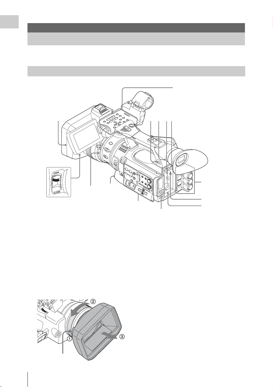
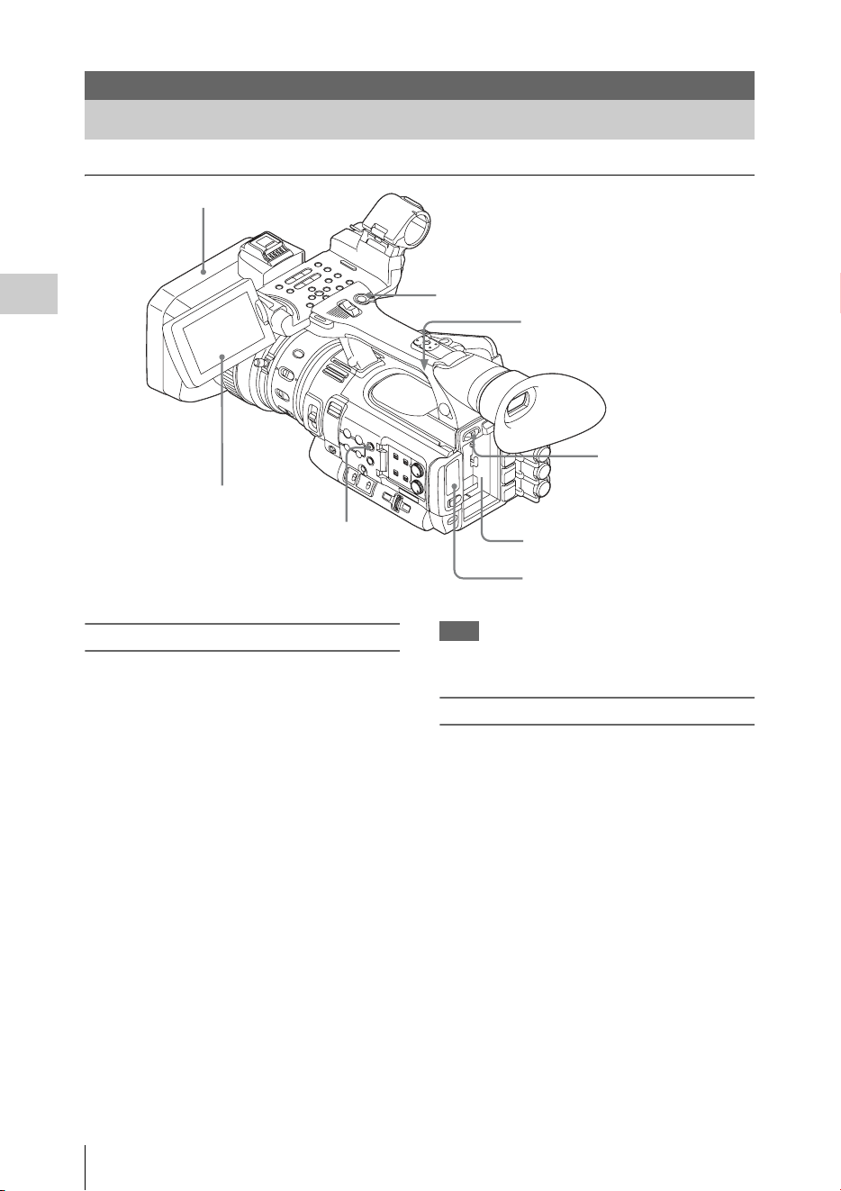
Part Identification
8
Overview
For functions and usage, see the pages in parentheses.
1. Lens hood
Attach
Insert the hood by aligning the mark on the
camcorder and hood then turn the hood
clockwise (in the opposite direction of arrow 2
in the illustration below), with the front of the
camcorder facing forward, until the hood is
locked.
Detach
1 Press the PUSH (lens food removing) button,
2 turn the hood in the direction of the arrow, 3
then withdraw it.
2. Headphone connector (stereo mini jack)
(page 38)
3. Rear remote sensor
4. Power switch (page 19)
5. BATT RELEASE button (page 18)
6. DC IN connector (page 19)
7. Battery pack receptacle (page 18)
8. WHITE BAL (automatic white balance
adjustment) button (page 32)
9. Lens cap open/close lever (page 28)
Overview
Part Identification
Camcorder
Operation panel on the
handle
(page 10)
Card slot block (page 12)
Side operation panel
(page 11)
Rear connector
panel
(page 12)
1
2
3
4 5
9
6
7
Lens control
block
(page 11)
8
PUSH (lens hood
removing) button
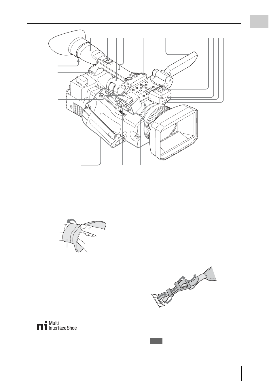
Part Identification
9
Overview
1. Viewfinder (page 20)
How to attach the EVF large eyecup
Stretch the EVF large eyecup for attaching to
the viewfinder and insert it aligning with the
horizontal groove of the eyecup.
2. Rear accessory shoe (page 10)
3. External microphone holder (page 37)
4. LCD (Liquid Crystal Display) monitor
(page 20)
5. Front accessory shoe
The cover is attached. You can mount an
accessory compatible with the Multi
Interface Shoe.
For details about the compatible accessories
with the Multi Interface Shoe, contact your
dealer.
6. Built-in stereo microphone (page 37)
7. REC/TALLY lamp
8. Front IR remote control receptor
9. Built-in speaker (page 91)
10. AUDIO IN CH-1/CH-2 connectors (XLR)
and input selection (LINE/MIC/
MIC+48V) switches (page 37)
11. Microphone cable holder (page 37)
12. Hooks for the shoulder strap
Attach the supplied shoulder strap as shown
below.
13. Eyepiece focusing knob (page 21)
14. GPS module
This part contains the GPS module.
Note
Holding this part while using GPS functions may
affect the positioning accuracy.
Controls on the grip
(page 13)
2
356
9
78
13
12
11
1
12
4
10
14
EVF large eyecup
(supplied)
1
2
3
4
Part Identification
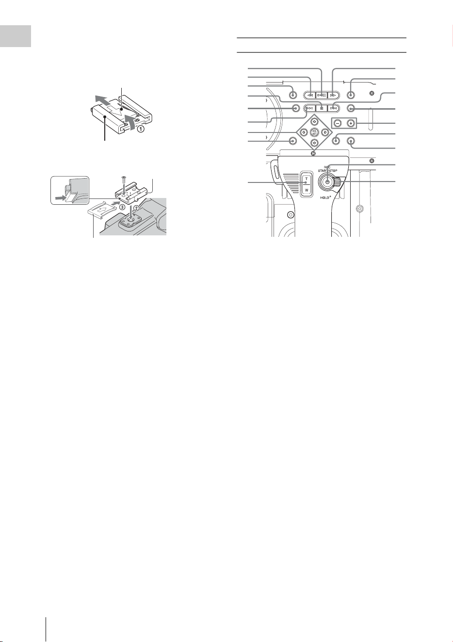
10
Overview
To mount the accessory shoe
Mount the accessory shoe on the accessory shoe
mount as illustrated.
1. Lift the edge of the accessory shoe plate and
pull it in the direction opposite to that of the
arrow on the accessory shoe plate and
remove it from the accessory shoe.
2. Place the accessory shoe so its protrusions
match recesses of the accessory shoe mount,
then fix it to the mount with four screws.
3. Insert the accessory shoe plate in the
direction of the arrow on the plate surface
until the end of the plate engages the end of
the shoe.
To remove the accessory shoe
Remove the shoe plate in the same way as step 1
of “To mount the accessory shoe.” Loosen the 4
screws and remove the accessory shoe from the
accessory shoe mount.
Operation panel on the handle
1. PLAY/PAUSE button (page 90)
2. F REV (fast reverse) button (page 91)
3. THUMBNAIL button (page 88)
4. STOP/CAM button (page 88)
5. STATUS (status display on/off) button
(page 98)
6. PREV (previous) button
7. Up/down/left/right buttons, SEL/SET
(select/set) button (page 103)
8. MENU (menu display on/off) button (page
103)
9. On-handle ZOOM button (page 34)
10. F FWD (fast forward) button (page 91)
11. LCD BRIGHT (LCD brightness
adjustment) button (page 20)
12. NEXT (clip directional jump) button
(page 91)
13. DISPLAY button (page 14)
14. VOLUME (monitor volume) buttons
(page 38)
15. CANCEL button
16. DURATION/TC/U-BIT (time data
selection) button (page 36)
17. REC START/STOP button (page 29)
18. REC HOLD lever (page 29)
Accessory shoe
Accessory shoe plate
Accessory shoe
Accessory shoe plate
1
2
3
4
5
6
10
9
7
8
11
12
13
14
15
16
17
18
Part Identification
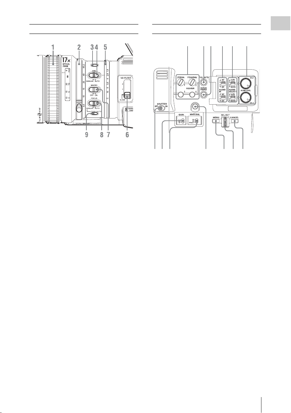
11
Overview
Lens control block
1. Focus ring (page 35)
2. Zoom ring (page 34)
3. STEADY SHOT button (page 36)
4. IRIS switch (page 34)
5. Iris ring (page 34)
6. ND FILTER select switch (page 31)
7. MACRO switch (page 36)
8. FOCUS switch (page 35)
9. PUSH AUTO (momentary auto focus)
button (page 35)
Side operation panel
1.
ASSIGN (assignable) 1/2/3/4 buttons (page
40)
“Zebra” is set to ASSIGN 1 and “Peaking” is
set to ASSIGN 2 by default.
2. FULL AUTO button and indicator (page
28)
3. PICTURE PROFILE button (page 46)
4. AUDIO IN (audio input selection)
switches (page 37)
5. AUDIO SELECT (audio level control
mode selection) switches (page 38)
6. AUDIO LEVEL CH-1/CH-2 knobs (page
38)
7. SHUTTER switch (page 33)
8. GAIN switch (page 33)
9. WHITE BAL (white balance memory)
switch (page 31)
10. ASSIGN (assignable) 5 button (page 40)
11. MENU (menu display on/off) button (page
103)
12. SEL/SET dial (jog dial) (page 103)
It functions accordingly when you turn it up or
down, or you push it horizontally.
It is called the “jog dial” in the subsequent
operating instructions.
13. CANCEL button
1234
987
56
10
11 12 13
Part Identification
12
Overview
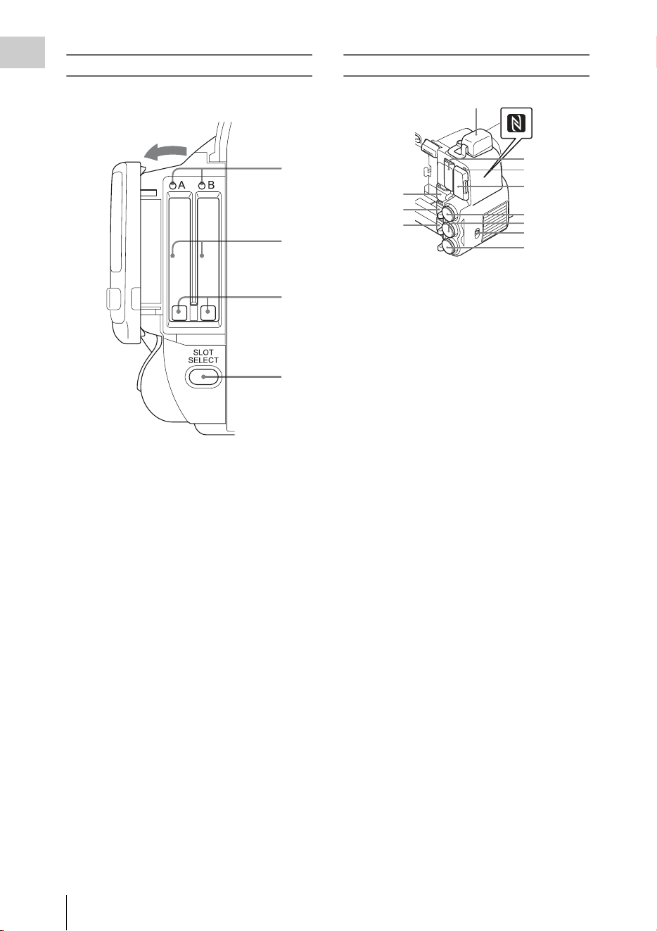
Card slot block
The SxS memory card slots and EJECT buttons
are located behind the cover.
1. ACCESS lamps (page 23)
2. SxS memory card slots (page 23)
3. EJECT (SxS memory card eject) buttons
(page 23)
4. SLOT SELECT (SxS memory card select)
button (page 23)
Rear connector panel
1. External device connector (page 26, 63)
2. PC connector (page 139)
3. i.LINK (HDV/DV) connector (4-pin, S400
conforming to IEEE1394) (page 139)
4. A/V OUT (audio/video multi output)
connector (page 139)
5. N mark
• Hold a NFC-compatible smartphone near
this mark when making wireless
connection between the camcorder and
smartphone. For details, refer to the
operating instructions of the smartphone.
• NFC (Near Field Communication) is the
international standard for the short range
radio communication technique.
6. HDMI OUT connector (page 138)
7. SD card ACCESS lamp
Lights in red while accessing the loaded SD
card.
8. SD card slot for proxy recording (page 60)
9. SDI OUT (serial digital output) connector
(BNC type) (page 138)
10. TC IN (timecode input)/TC OUT
(timecode output) connector (BNC type)
(page 144)
11. IN/OUT (input/output change) switch
(page 145)
Set this to IN to select TC IN and GENLOCK
IN, and set this to OUT to select TC OUT and
VIDEO OUT.
12. GENLOCK IN/VIDEO OUT (analog
video output) connector (BNC type) (page
138, 144)
1
2
3
4
Open the cover
1
2
3
4
5
6
7
8
9
10
11
12
Part Identification
13
Overview
Controls on the grip
1.
REC REVIEW button (page 29)
2. Power zoom lever (page 34)
3. FOCUS MAG button (page 35)
4. LENS REMOTE (lens remote controller)
connector (page 35)
5. REC START (start/stop recording)
button (page 29)
Bottom
1.
ZOOM (zoom mode switching) switch
(page 34)
2. Tripod receptacles
Note
Check that the size of the hole matches the screw of
the tripod. If they do not match, the camcorder
cannot be attached to the tripod securely, and this
may lead to the physical injury of the camera
operator.
3. Backup battery holder (page 166)
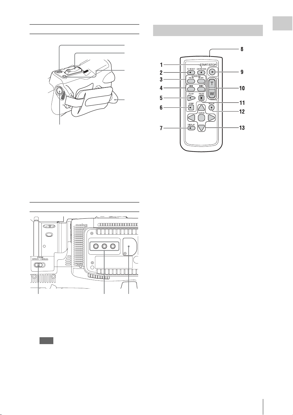
1. DATA CODE button
This button does not work on the camcorder.
2. TC RESET (timecode reset) button
3. SCAN/SLOW (reverse high speed
playback/high speed playback) buttons
4. . > (PREV/NEXT(clip reverse/
forward direction jump)) buttons
5. PLAY button
6. STOP button
7. DISPLAY button
8. Transmitter
9. START/STOP (recording start/stop)
button
10. Power zoom lever
11. PAUSE button
12. MODE button
This button does not work on the camcorder.
13. b/B/v/V/ENTER buttons
1
2
3
4
5
1
23
IR Remote Commander (Supplied)
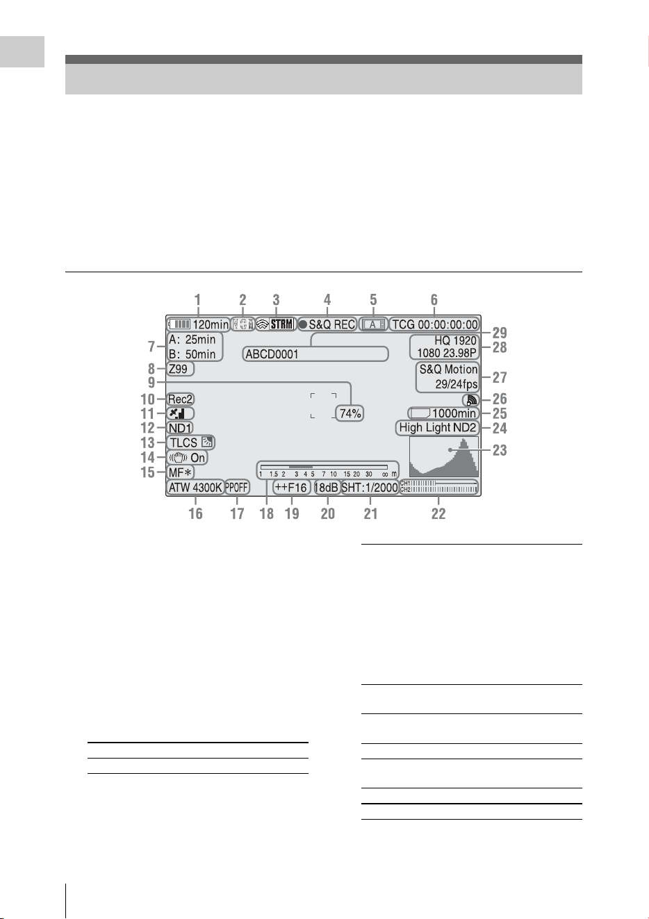
On-Screen Indications
14
Overview
While recording (or standing by to record), pressing the DISPLAY button displays the statuses and
settings of this unit on the LCD monitor/viewfinder screen.
Remarks
[M]: The indication of the items named with this suffix can be independently turned on/off with “Display
On/Off” of the LCD/VF SET menu (page 120).
[A]: The indication of items named with this suffix can be turned on/off using the assignable buttons to
which the corresponding on/off functions have been assigned (page 40).
[D]: The settings of the items named with this suffix can be changed using the Direct menu on the screen
(page 16).
1. Battery remaining/DC IN voltage
indication [M] (page 18)
2. Network client mode status indication
The status of the connection in network client
mode is displayed (page 76).
3. i.LINK status indication/Streaming status
indication
The status of the connected equipment (page
141) or the streaming status is displayed (page
75).
4. Special recording/operation status
indication
On-Screen Indications
SD
zREC Recording in progress
STBY Standby for recording
CONT Standby for Clip Continuous
Recording
“CONT” lit: Indicates that a
clip is being continued when
using Clip Continuous
Recording.
“CONT” flashing: Indicates
that there is no continuing clip
when using Clip Continuous
Recording.
zS&Q REC Slow & Quick Motion
recording in progress
S&Q STBY Standby for Slow & Quick
Motion recording
zINT REC Interval Recording in progress
INT STBY Standby for Interval
Recording
zFRM REC Frame Recording in progress
FRM STBY Standby for Frame Recording
On-Screen Indications
15
Overview
5. Media status indication
6. Time data indication [M] (page 36)
7. Media remaining indication [M] (page 24)
8. Zoom position indication [M] (page 34)
9. Brightness level indication [M][A]
10. Synchronous recording indication [M]
(page 138)
“Rec2” appears when recording while “SDI
Rec Control” of the VIDEO SET menu is set
to “HD SDI Remote I/F.”
“Rec2-P” appears when recording
synchronously while “Proxy” of the
CAMERA SET menu is set to “On.”
11. GPS status indication
The GPS positioning status are displayed as
icons.
“Obtaining Location Information (GPS)” (page 58)
12. ND FILTER position [M]
Displays the selected ND filter number (page
31).
13. TLCS mode indication [M][D] (page 113)
14. Steady Shot indication [M] (page 36)
15. Focus mode indication [M] ([D] only in MF
mode) (page 35)
16. White balance mode and color
temperature indications [M][D] (page 31)
17. Picture profile indication [M][D] (page 46)
18. Depth-of-Field bar indication [M][A]
19. Iris position indication [M][D] (page 34)
20. Gain indication [M][D] (page 33)
21. Shutter mode/shutter speed indication
[M][D] (page 33)
22. Audio level meters [M]
23. Histogram indication [M][A]
24. Video level cautioning indication [M]
/Recommended ND filter number
indication/Clip uploading status
indication
The clip uploading status indication is displayed
when connected via wireless LAN. The number
of remaining clips for uploading and uploading
rate are displayed.
25. SD card remaining space indication
The remaining space of the SD card is displayed
while the SD card is inserted in the card slot of
the camcorder (page 60).
zCACHE z in green: Standby for
Picture Cache Recording
z in red: Picture Cache
Recording in progress
zSML REC Simultaneous Recording in
the 2 slots in progress
SML STBY Standby for Simultaneous
Recording of the 2 slots
Memory card in slot A is active.
Memory card in slot B is active.
Backlight mode
Standard mode
Spotlight mode
On-Screen Indications
16
Overview
26. Network connection status indication
The network connection status is displayed as icons.
1)When the USB wireless LAN module is not connected, or the SSID is not set.
2)When the 3G/4G/LTE modem (optional) is not connected
3)When the USB-RJ45 adaptor (optional) is not connected
27. Special recording mode indication [M] ([D]
only in Slow & Quick Motion Standby)
28. Video format indication [M] (page 30)
29. Clip name indication [M] (page 29)
The settings of the items named with a suffix [D]
can be changed using the Direct menu on the
screen.
Select “All,” “Part,” or “Off” for Direct Menu
using “Direct Menu” (page 137) of the OTHERS
menu.
Note
When the indicator of the FULL AUTO button is lit, the
Direct Menu operation is disabled for the functions that
are forcibly set to the automatic mode in Full Auto mode
(page 28).
Conditions Icon
NETWORK SET
menu>”NW&
Proxy”/”USB”
NETWORK SET
menu>”Network
Mode
Network
connection status
“Off” or “USB A” – –
“Network&Proxy” “Off” –
“Access Point” Preparing Wi-Fi
Flashing
Connected to Wi-Fi AP
Wi-Fi cannot be
connected
1)
“Station” Preparing Wi-Fi
Flashing
Connected to Wi-Fi
Intensity 1 Intensity 2
Intensity 3 Intensity 4
The icon changes depending on the
radio wave intensity.
Disconnected from Wi-
Fi
No radio wave
Wi-Fi cannot be
connected
1)
Modem Preparing 3G/4G
Flashing
Connected to 3G/4G 3G/4G
Disconnected from 3G/
4G
3G/4G
3G/4G cannot be
connected
2)
Wired LAN Preparing LAN
Flashing
Connected to LAN LAN
Disconnected from
LAN
LAN
LAN cannot be
connected
3)
Frame Rec Frame Rec mode
Interval Rec Interval Rec mode
S&Q Motion
xx/xx fps
Slow & Quick Motion mode
Direct Menu Operation

On-Screen Indications
17
Overview
1 When the camcorder’s status or settings
are displayed on the screen, press the
SEL/SET button (page 10) or the jog
dial (page 11).
If “Direct Menu” is set to “All” or “Part,” the
cursor is displayed on one of the items for
which the Direct menu operation is
permitted.
2 Press the up/down/left/right buttons
(page 10) or rotate the jog dial to set the
cursor to the item to be operated, then
press the SEL/SET button or the jog
dial.
The Direct menu of the selected items appears.
3 Press the up/down/left/right buttons or
rotate the jog dial to select a setting,
then press the SEL/SET button or the
jog dial.
The menu disappears, and the new setting is
displayed.
Power Supply
18
Preparations
You can use a battery pack or AC power via an
AC adaptor.
For safety, use only the Sony battery packs and
AC adaptors listed below.
Lithium-ion Battery Pack
BP-U30
BP-U60
BP-U60T
BP-U90
Battery Charger/AC Adaptor
BC-U1
BC-U2
The life expectancy of the AC adapter and the
electrolytic capacitor is about 5 years under
normal operating temperatures and normal usage
(8 hours per day; 25 days per month). If usage
exceeds the above normal usage frequency, the
life expectancy may be reduced correspondingly.
The battery terminal of this unit (the connector for
battery packs and AC adaptors) is a consumable
part.
Power may not be supplied to the unit properly if
the pins of the battery terminal are bent or
deformed by shock or vibrations, or if they
become corroded due to prolonged outdoor use.
Periodic inspections are recommended to keep
the unit working properly and to prolong its
usable lifetime.
Contact a Sony service or sales representative for
more information about inspections.
Batteries shall not be exposed to excessive heat
such as sunshine, fire or the like.
Danger of explosion if battery is incorrectly
replaced. Replace only with the same or
equivalent type recommended by the
manufacturer.
When you dispose of the battery, you must obey
the law in the relative area or country.
Note
The AC adaptor cannot be connected to the camcorder
while the battery pack is inserted.
Fully insert the battery pack into the battery pack
receptacle (page 8), then slide it down to lock it.
To remove the battery pack, press and hold the
BATT RELEASE button (page 8), slide the
battery pack upward to unlock it, then pull it out.
Notes
• Before use, charge the battery pack with the supplied
BC-U1 or BC-U2 Battery Charger.
• A warm battery pack immediately after use may not be
able to be fully recharged.
• The high-capacity BP-U90 Battery Pack is large, and
protrudes from the camcorder when attached. When
using the camcorder with the BP-U90 attached for
extended recording periods, Sony recommends
attaching the camcorder to a tripod for convenience.
Checking battery charge remaining
When recording or playback is in progress on the
battery pack, an icon to show the current battery
charge level and usage time remaining are
displayed on the LCD monitor/viewfinder screen
(page 14).
The camcorder indicates the remaining usage
time in minutes by calculating the available time
with the battery pack if operation is continued at
the current rate of power consumption.
Preparations
Power Supply
WARNING
CAUTION
Using a Battery Pack
Icon Remaining
100% to 91%
90% to 71%
70% to 51%
50% to 31%
30% to 11%
10% to 0%
Power Supply
19
Preparations
If the battery charge remaining becomes
low
If the battery charge remaining decreases to a
certain level during operation (Low BATT
status), a low-battery message, flashing of the
tally lamps, and a beep sound will warn you.
If the remaining further decreases to a level at
which operation cannot be continued (BATT
Empty status), a battery-empty message appears.
Replace the battery pack with one that is fully
charged.
To change the message levels
The Low BATT level is set to 10% of full charge,
and the BATT Empty level is set to 3% of full
charge at the factory. These settings can be
changed with “Battery Alarm” (page 132) of the
OTHERS menu.
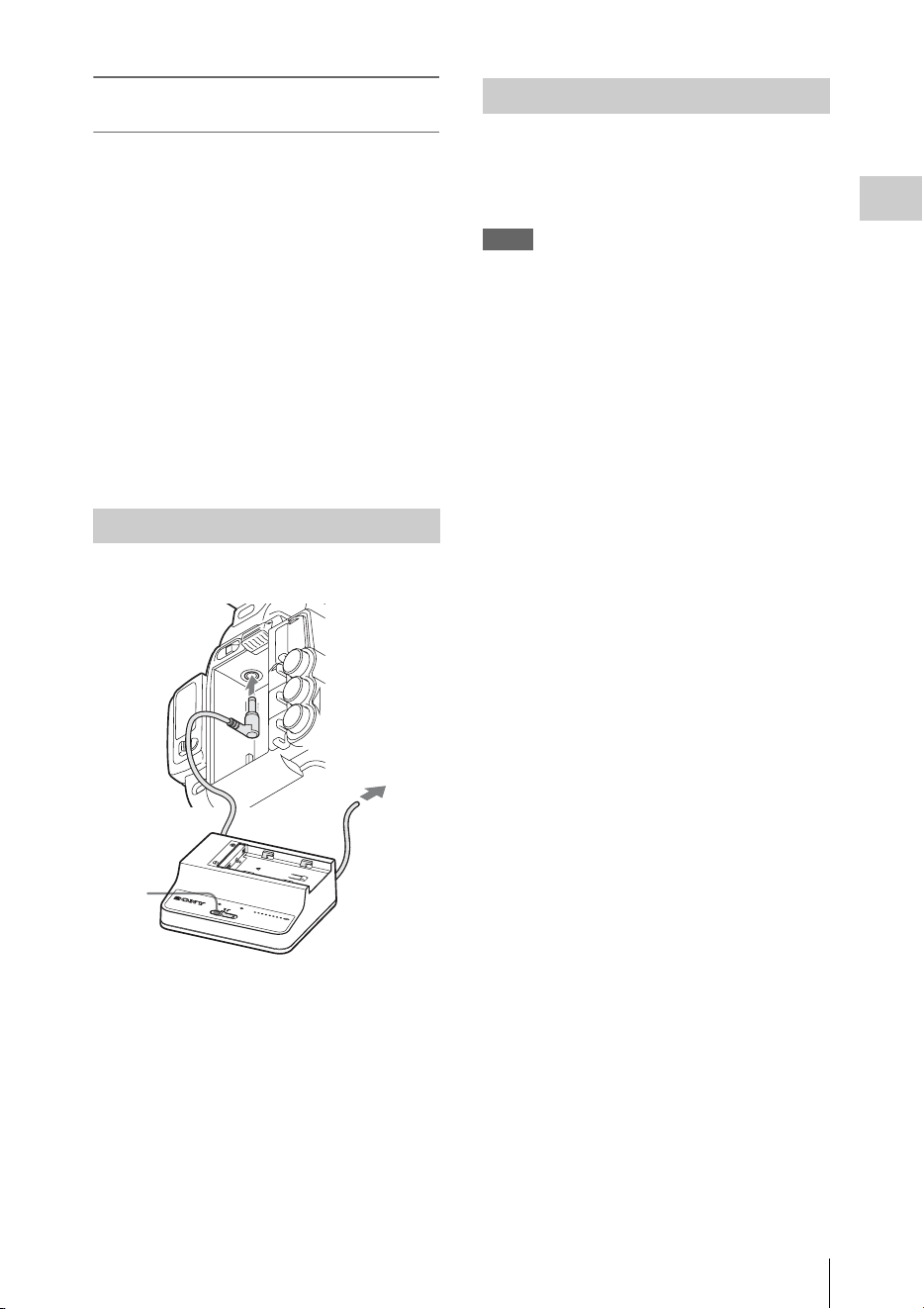
Connection example: when connecting BC-U1
1 Connect the DC power output cable of
the BC-U1 to the DC IN connector of
the camcorder.
2 Connect the power cord of the BC-U1 to
an AC power source.
3 Set the mode switch of the BC-U1 to the
DC OUT position.
To turn the power on, set the power switch (page
8) to the ON position (the ? position). To turn the
power off, set the power switch to the OFF
position (the 1 position).
Notes
• This camcorder uses a little standby power even when
the power switch is set to OFF. Remove the battery
pack if the camcorder will not be used for a prolonged
period.
• When removing the battery pack or the DC IN power,
be sure to first set the power switch to the OFF
position. Removing the battery pack or the DC IN
power while the camcorder is on may cause damage to
the camcorder or the SxS memory card.
Using AC Power (DC IN Power)
DC OUT
CHARGE
BATTERY CHARGER
BC-U1
0% 80
100
BC-U1
1
2
3
Turning the Power On/Off

Setting the Clock / Adjusting the LCD Monitor and Viewfinder
20
Preparations
When you turn the camcorder on for the first time
after purchasing or replacing the backup battery
(page 166), the Initial Setting display appears on
the LCD monitor/viewfinder screen.
Set the date and time of the built-in clock, using
this display.
Time Zone
The value shows the time difference from UTC
(Coordinated Universal Time).
Change the setting if needed.
Setting the time and date
Press the up/down/left/right buttons (page 10) or
turn the jog dial (page 11) to move the cursor,
then press the SEL/SET button or the jog dial to
set each menu item. When you press the SEL/
SET button or the jog dial when the cursor is on
“Finish,” the Initial Setting display disappears
and the clock setting is completed.
After the Initial Setting display disappears, “Time
Zone” (page 130) and “Clock Set” (page 130) of
the OTHERS menu can be used to set “Time
Zone” and “Date/Time.”
Notes
• If the clock setting is cleared because of exhaustion of
the backup battery while no operation power was being
supplied (no battery pack and no DC IN connection),
the Initial Setting display will be displayed when you
turn the camcorder on at the next opportunity.
• While the Initial Setting display is shown, no other
operation except turning the power off is permitted
until you finish the setting for this display.
The LCD monitor turns on when it is opened and
turns off when it is returned to the park position.
Adjusting the angle
It can be rotated as much as 90 degrees in the
direction facing the subject and as much as 180
degrees in the opposite direction.
When you rotate it 90 degrees toward the subject,
the image on the monitor becomes upside down,
indicating the mirror image of the subject. The
display direction of the textual information is
converted to the readable direction.
Adjusting the backlight
Press the LCD BRIGHT button (page 10) to
adjust the brightness of the backlight.
Adjusting the color, contrast, and
brightness
These adjustments can be made using “LCD”
(page 119) of the LCD/VF SET menu. These
adjustments of the LCD monitor have no effect on
pictures being recorded.
If the picture on the LCD monitor is hard to view
under bright ambient light, you can use the
viewfinder to check the picture.
Do not leave the camcorder with the eyepiece of
the viewfinder facing the sun. Direct sunlight can
enter through the eyepiece, be focused in the
viewfinder, and cause fire.
Hereafter the viewfinder is referred to as “EVF”
(abbreviation of Electronic Viewfinder).
Setting the Clock Adjusting the LCD
Monitor and Viewfinder
Adjusting the LCD Monitor
Adjusting the Viewfinder
Caution
Using the IR Remote Commander
21
Preparations
Turning the EVF on/off
With the factory setting, the EVF is turned on
when the LCD monitor is in its park position or is
rotated to face the subject.
You can change the setting so that the EVF is
always on regardless of the status in the LCD
monitor, using “EVF” (page 119) of the LCD/VF
SET menu. Change the “Power” setting from
“Auto” to “On.”
Adjusting the focus in the EVF
The eyepiece focusing (diopter compensation)
knob (page 9) enables adjustment to match the
eyesight of the operator, who can then view the
image clearly through the eyepiece.
Adjusting the backlight
The brightness of the backlight for the EVF can
be switched between High and Low.
Set “Backlight” in “EVF” (page 119) of the LCD/
VF SET menu.
Switching between color and
monochrome modes
For the EVF screen, color or monochrome display
can be selected.
Set “Mode” in “EVF” (page 119) of the LCD/VF
SET menu.
Select “B&W” if checking the subject and
focusing are easier on the monochrome display.
If you assign “EVF Mode” to one of the
assignable buttons (page 40), you can switch
between color and monochrome by pressing the
button.
Adjusting the contrast and brightness
Use “EVF” (page 119) of the LCD/VF SET menu
to make adjustments. Adjusting the brightness
and other items has no effect on pictures being
recorded.
Before use
Before you use the supplied IR Remote
Commander for the first time, pull out the
insulation sheet from the battery holder.
A CR2025 lithium battery is set in the holder at
the factory.
Using the IR Remote Commander
For controlling the camcorder from the IR
Remote Commander, activate the remote control
function of the camcorder after turning the power
on.
Activating/deactivating the remote control
function can be achieved using the Setup menu.
To activate using the menu
Press the MENU button to set the camcorder to
Menu mode, then set “IR Remote” (page 132) of
the System menu to “On.”
To activate using the assignable button
If you assign “IR Remote” to one of the
assignable buttons (page 40), you can switch
between activating and deactivating the remote
control function by pressing the button.
Notes
• Aim the IR Remote Commander towards the remote
sensor to operate your camcorder.
• Point the remote sensor away from strong light sources
such as direct sunlight or overhead lighting. Otherwise,
the IR Remote Commander may not function properly.
• When you are operating with the IR Remote
Commander supplied with your camcorder, your video
device may also operate. In that case, select a
commander mode other than DVD2 for your video
device, or cover the sensor of your video device with
black paper.
• The remote control function is deactivated
automatically when the camcorder is turned off to
prevent a malfunction. To use the remote control
function, activate it when the camcorder is turned on.
Using the IR Remote
Commander
Insulation sheet

Using SxS Memory Cards
22
Preparations
Replacing the battery in the IR Remote
Commander
Use a commercially available CR2025 lithium
battery. Do not use any battery other than a
CR2025.
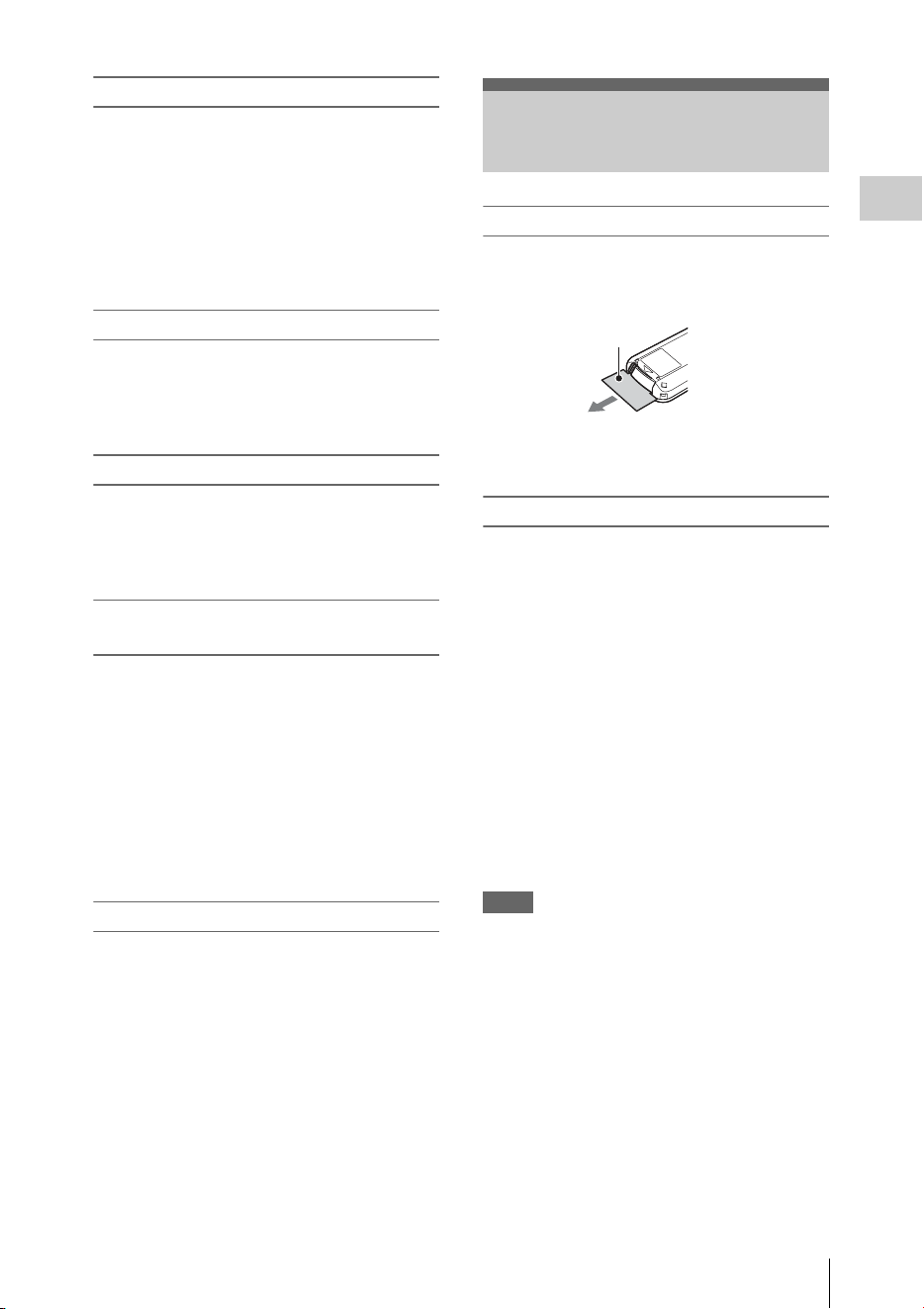
1. While pressing on the tab, inset your
fingernail into the slit to pull out the battery
case.
2. Place a new battery with the + side facing up.
3. Insert the battery case back into the IR
Remote Commander until it clicks.
• Battery may explode if mistreated.
Do not recharge, disassemble, or dispose of in
fire.
• Batteries shall not be exposed to excessive heat
such as sunshine, fire or the like.
Danger of explosion if battery is incorrectly
replaced. Replace only with the same or
equivalent type recommended by the
manufacturer.
When you dispose of the battery, you must obey
the law in the relative area or country.
This camcorder records audio and video on SxS
memory cards (optional) inserted in the card slots.
Usable SxS memory cards
Use the following Sony-made SxS memory cards.
Operations are not guaranteed with memory cards
other than the following cards.
SxS PRO+ series
SxS PRO series
SxS-1 series
These cards comply with the ExpressCard
standard.
For details on using SxS memory cards and usage-
related precautions, refer to the instruction manual
for the SxS memory card.
SxS, SxS PRO and SxS-1 are trademarks of Sony
Corporation.
The ExpressCard word mark and logo are owned
by Personal Computer Memory Card
International Association (PCMCIA) and are
licensed to Sony Corporation. All other
trademarks are the property of their respective
owners.
Note
The Slow & Quick Motion recording (page 43) with
XAVC-I format may not be performed correctly
depending on the SxS-1 memory card used. An SxS PRO
or SxS PRO+ memory card is recommended.
WARNING
CAUTION
Tab
Using SxS Memory
Cards
About SxS Memory Cards

Using SxS Memory Cards
23
Preparations
Inserting an SxS memory card
1
Open the cover of the card slot block
(page 12).
2 Insert the SxS memory card into the slot
with the SxS label facing right.
The ACCESS lamp (page 12) lights in red
then changes to green once the memory card
is ready for use.
3 Close the cover.
Status indications by the ACCESS lamps
Card slots A and B are accompanied by the
respective ACCESS lamps to indicate their
statuses.
Removing an SxS memory card
1 Open the cover of the card slot block,
press the EJECT button (page 12), then
pull the button out.
2 Press the EJECT button again to
remove the card.
Note
Data are not guaranteed if the power is turned off or a
memory card is removed while the card is being
accessed. All data on the card may be destroyed. Be sure
that the ACCESS lamps are lit in green or off when you
turn off the power or remove memory cards.
When SxS memory cards are loaded in both card
slots A and B, press the SLOT SELECT button
(page 12) to select the card you wish to use.
If a card becomes full during recording, switching
to the other card is automatically executed.
Note
The SLOT SELECT button is disabled while playback is
in progress. Switching is not executed even if you press
the button. The button is enabled while the thumbnail
screen is displayed (page 88).
For an SxS memory card that is not formatted or
that was formatted with another system, the
message “Unsupported File System” is displayed
on the LCD monitor/EVF screen.
Format the card as instructed in “To execute
formatting” below.
To execute formatting
Using “Format Media” (page 135) of the
OTHERS menu, specify “Media(A)” (slot
A) or “Media(B)” (slot B) then select
“Execute.” On a confirmation message,
select “Execute” again.
The in-progress message and status bar (%) are
displayed, and the ACCESS lamp lights in red.
When formatting is completed, the completion
message is displayed for three seconds.
Recording/playback during formatting
You can perform recording or playback using the
SxS memory card in the other card slot while
formatting is in progress.
If formatting fails
A write-protected SxS memory card or memory
card that cannot be used with this camcorder will
not be formatted.
As a warning message is displayed, replace the
card with an appropriate SxS memory card, as per
the instructions in the message.
Inserting/Removing an SxS
Memory Card
Lamp Slot statuses
Lights in
red
Accessing the loaded SxS memory card
(writing/reading data)
Lights in
green
Standby (ready for recording or
playback using the loaded SxS memory
card)
Off • No SxS memory card is loaded.
• The loaded card is invalid.
• An SxS memory card is loaded, but
another slot is active.
Switching Between SxS Memory
Cards
Formatting an SxS Memory Card

Using SxS Memory Cards
24
Preparations
Notes
• Use the format function of this camcorder to format
SxS memory cards for use on this camcorder. The
formats of cards formatted on other devices are not
recognized as valid formats, making it necessary to
format them again on this camcorder.
• All the data, including recorded pictures and setup
files, are erased when a memory card is formatted.
While recording (or standing by to record), you
can check the time remaining for the SxS memory
cards loaded in the card slots on the LCD
monitor/EVF screen (page 14).
The available time for recording with the current
video format (recording bit rate) is calculated
according to the remaining space of each card and
displayed in time units of minutes.
The remaining can also be checked in a meter
format on the Battery/Media status screen (page
99).
Notes
• A icon appears if the memory card is write-
protected.
• The displayed remaining time is only a guide.
The actual remaining time may be less than the one
displayed since the memory card has data other than
video such as the management area.
Replacing an SxS memory card
• If the available time on two cards in total
becomes less than 5 minutes, a message “Media
Near Full,” flashing of the tally lamps, and a
beep sound will warn you. Replace the cards
with those with sufficient space.
• If you continue recording until the total
remaining time reaches zero, the message
changes to “Media Full,” and recording stops.
Note
Approximately 600 clips can be recorded on one SxS
memory card at maximum.
If the number of recorded clips reaches the limit, the
remaining time indication becomes “0,” and the message
“Media Full” is displayed.
If an error occurs with data in a memory card for
some reason, the card must be restored.
If an SxS memory card that needs to be restored
is loaded, a message that prompts you to execute
a restore operation is displayed on the LCD
monitor/EVF screen.
To restore a card
Select “Execute” by pressing the up/down/
left/right buttons or turning the jog dial,
then push the SEL/SET button or the jog
dial.
During restoration, the in-progress message and
status bar (%) are displayed, and the ACCESS
lamp is lit in red.
When restoration is completed, the completion
message is displayed for three seconds.
If restoration fails
• A write-protected SxS memory card or one on
which an error occurred cannot be restored. For
such a card, a warning message is displayed.
Release the write protection or replace the card,
as per the instructions in the message.
• An SxS memory card on which an error
occurred may become usable again through
repeated formatting.
• In some cases, only parts of clips cannot be
restored. Playback of the restored clips becomes
possible again.
• The following operation may restore an SxS
memory card for which the message “Could not
Restore Some Clips” is repeatedly displayed
each time you try the restoration process:
1 Copy necessary clips to another SxS memory
card, using the copy function (page 94) of the
camcorder or the dedicated application
software (supplied) (page 140).
2 Format the problem SxS memory card, using
the format function of this camcorder.
3 Return the necessary clips to the SxS
memory card by copy operation.
Recording/playback during restoration
You can perform recording or playback using the
SxS memory card in the other card slot while
restoration is in progress.
Note
For restoration of media recorded with this unit, be sure
to use this unit. Media recorded with a device other than
this unit or with another unit of different version (even of
the same model) may not be restored using this unit.
Checking the Remaining Time
Available for Recording
Restoring an SxS Memory Card

Using Other Media
25
Preparations
Notes
• Medias other than an SxS memory card cannot obtain
the high reliability and durability equivalent to an SxS
memory card for professional use.
• Not all memory cards have been verified to function
with this camcorder. For compatible memory cards,
contact your dealer.
• When you use media with this camcorder, format the
media using the unit’s formatting function.
By using an optional QDA-EX1 Media Adaptor,
you can insert an XQD memory card into the SxS
memory card slot and use it instead of an SxS
memory card.
For details on using a QDA-EX1 Media Adaptor,
refer to the instruction manual supplied with it.
Notes
• High-speed playback (page 10) may not be properly
achieved with an XQD memory card.
• Recording with XAVC-I format or the Slow & Quick
Motion recording (page 43) may not be performed
correctly depending on the XQD memory card used.
An SxS PRO or SxS PRO+ memory card is
recommended.
Formatting
When you use an XQD memory card with this
camcorder, formatting is required.
An XQD memory card to be used with this
camcorder must be formatted using the format
function of this camcorder.
It is also necessary to format an XQD memory
card for use if a caution message is displayed
when you mount the XQD memory card.
For an XQD memory card that was formatted
with another system unsupported by this
camcorder, the message “Unsupported File
System” is displayed on the LCD monitor/EVF
screen.
Format the XQD memory card as instructed
below.
To execute formatting
Using “Format Media” (page 135) of the
OTHERS menu, specify “Media(A)” (slot
A) or “Media(B)” (slot B), then select
“Execute.”
An in-progress message and status bar (%) are
displayed, and the ACCESS lamp lights in red.
When formatting is completed, a completion
message is displayed for three seconds.
Note
When formatting, all data in an XQD memory card—
including protected images—are erased and cannot be
restored.
Connection between the camcorder and a PC
To use an XQD memory card in which data have
been recorded with an XDCAM/XDCAM EX-
series product, insert it into the slot of the
camcorder and connect between the PC and this
camcorder using a USB cable.
To use media formatted with this camcorder in
the slots of other devices
Make a backup of the media, then format it using
the other device.
Use of the optional MEAD-SD02 Media Adaptor
permits you to insert an SD card into the SxS
memory card slot and use it for recording and
playback in the same way as with an SxS memory
card.
For details on use of the MEAD-SD02 Media
Adaptor, refer to the operating instructions supplied
with the respective adaptor.
Note
High-speed playback (page 10) may not be properly
achieved with an SD card.
SDHC card (FAT only)
Class 10 SDHC card
Note
SDHC cards cannot be used in UDF and exFAT.
SDXC card (exFAT only)
Class 10 SDXC card
Notes
• SDXC cards can only be used in exFAT.
• When you use an SDXC card, do not use other types of
memory cards simultaneously. If you use other types
of media simultaneously, switching to other media
cannot be executed when the media has no space while
recording.
Using Other Media
XQD Memory Cards
SD Cards

Using Other Media
26
Preparations
• Recording with XAVC-I format or the Slow & Quick
Motion recording (page 43) may not be performed
correctly depending on the SDXC card used. An SxS
PRO or SxS PRO+ memory card is recommended.
• An SDXC card recorded with the camcorder of the
PMW and PXW series may not be able to be used for
recording and playback with this unit depending on the
type of unit used. For details, contact your Sony dealer
or a Sony service representative.
Formatting
When you use an SD card with this camcorder,
formatting is required.
An SD card to be used with this camcorder must
be formatted using the format function of this
camcorder.
It is also necessary to format an SD card for use if
a caution message is displayed when you mount
the SD card.
For an SD card that was formatted with another
system unsupported by this camcorder, the
message “Unsupported File System” is displayed
on the LCD monitor/EVF screen.
Format the SD card as instructed below.
To execute formatting
Using “Format Media” (page 135) of the
OTHERS menu, specify “Media(A)” (slot
A) or “Media(B)” (slot B), then select
“Execute.”
An in-progress message and status bar (%) are
displayed, and the ACCESS lamp lights in red.
When formatting is completed, a completion
message is displayed for three seconds.
Note
When formatting, all data in an SD card including
protected images are erased and cannot be restored.
Connection between the camcorder and a PC
To use an SD card in which data have been
recorded with an XDCAM/XDCAM EX-series
product, insert it into the slot of the camcorder
and connect between the PC and this camcorder
using a USB cable.
To use media formatted with this camcorder in
the slots of other devices
Make a backup of the media, then format it using
the other device.
In UDF or exFAT, you can connect a USB flash
drive to the external device connector (page 12)
to record, save, and load the following data.
• “Loading a Planning Metadata file” (page 56)
• “Storing/Retrieving the Setting Data” (page
54)
Using Sony USB flash drives is recommended.
Notes
• Use USB flash drives with a capacity of 4 GB to
32 GB.
• USB flash drives other than those listed above may not
be recognized if connected to the external device
connector.
When using the external device connector
Set “NW&Proxy/USB” (page 124) of the
NETWORK SET menu to “USB A.”
Notes
• During this setting, “XAVC-L50 1920×1080/59.94P,
50P” and “XAVC-L35 1920×1080/59.94P, 50P”
cannot be selected for “Format” in “System” (page
133) of the OTHERS menu.
• During this setting, 60fps and 50fps cannot be selected
for “Frame Rate” in “S&Q Motion” when “Format” in
“System” of the OTHERS menu is set to “1920×1080/
29.97P, 23.98P, 25P.”
Formatting (Initializing) USB Flash
Drives
USB flash drives must be formatted with the
FAT32 file system.
Note
Before using a drive, format it on this camcorder or a PC.
If a drive formatted on a PC cannot be used, format it on
the camcorder.
1 Connect a USB flash drive to the
external device connector.
If the drive is unformatted or has been
formatted to other specifications, a message
to confirm whether formatting is to be
executed appears on the EVF screen.
2 Using the up/down/left/right buttons or
the jog dial, select “Execute,” then press
the SEL/SET button or the jog dial.
USB Flash Drives
UDF

Using Other Media
27
Preparations
The in-progress message and status bar (%)
are displayed, and formatting is started.
When formatting is completed, the message
“Format USB Memory Done” is displayed.
The \MSSONY\PRO\XDCAM\MEMDISC
folder and the \General\Sony\Planning folder
are automatically created in the drive.
If the format operation fails
A format operation may fail because the USB
flash drive is write protected, or because it is not
the type of drive specified for use with this
camcorder.
In this case, an error message appears. Follow the
instructions in the error message and exchange
the drive for one that can be used with this
camcorder.
Restoring USB Flash Drives
When you load a USB flash drive that cannot be
mounted normally because the file system is
destroyed, a message appears on the LCD
monitor/EVF screen to ask whether you want to
restore it.
Using the up/down/left/right buttons or the jog
dial, select “Execute,” then press the SEL/SET
button or the jog dial. The in-progress message
and status bar (%) are displayed, and restoration
is started.
When restoration is completed, the message
“Restore USB Memory Done” is displayed.
• “XQD” is a trademark of Sony Corporation.
Basic Operation Procedure
28
Recording
Preparations
1
Mount a fully charged battery pack.
2 Load SxS memory card(s).
If you load two cards, recording is continued
by automatically switching to the second
card when the first card becomes full.
3 Adjust the angle of the LCD monitor for
the best view.
When you wish to use the EVF, fold the LCD
monitor to its park position and adjust the
angle of the EVF.
4 Open the lens cap.
Pull up the lens cap open/close lever to open
the lens cap built in the lens hood.
5 Set the power switch to the ON position.
The recording screen is displayed.
When using the remote commander, activate the
remote control mode (page 21).
Note
When you hold the camcorder by the grip, support it
from underneath with your left hand.
Recording (Full Auto mode)
6
Press the FULL AUTO button so that
the button indicator lights.
Full Auto mode is turned on, TLCS (Total
Level Control System) (page 113) is
activated, Auto Iris, AGC (Auto Gain
Control), Auto Shutter, and ATW (Auto
Tracing White) are set to ON, then,
consequently the brightness and white
balance will always be adjusted
automatically.
When you wish to adjust them manually, turn
Full Auto mode off, and see;
“Iris” on page 34
“Gain” on page 33
“Electronic Shutter” on page 33
“White Balance” on page 31
Recording
Basic Operation Procedure
3
LCD monitor
angle
adjustment
1 Battery pack insertion
2 SxS memory card slots
9 REC REVIEW (on the grip)
5 Power switch:
ON (the " position)
7, 8 REC START/STOP
6
FULL AUTO
Open the lens cap
4
Basic Operation Procedure
29
Recording
Note
AF (Auto Focus) is not activated by setting the
camcorder to Full Auto mode.
For information of automatic focus adjustment,
see “Focus” (page 35).
7 Press the REC START/STOP button.
You can also start recording with the REC
START button on the grip.
(If you are using the IR Remote Commander, press
the START/STOP button.)
The TALLY lamp lights and recording
begins.
8 To stop recording, press the REC
START/STOP button again.
You can also stop recording with the REC
START button on the grip.
(If you are using the IR Remote Commander, press
the START/STOP button.)
Recording stops and the camcorder enters
STBY (recording standby) mode.
Note
If you press the REC START/STOP button to start next
recording while previous data writing is not completed,
the message “Cannot Proceed” may be displayed and
recording may not start.
To prevent a switching error
The REC START/STOP button on the handle is
incorporated with the REC HOLD lever. If the
REC START/STOP button on the handle will not
be used, it is recommended to set the lever to the
HOLD position to lock the button and prevent
unintentional starting/stopping of recording if
you accidentally press the button.
To unlock the button, return the lever to its
original position.
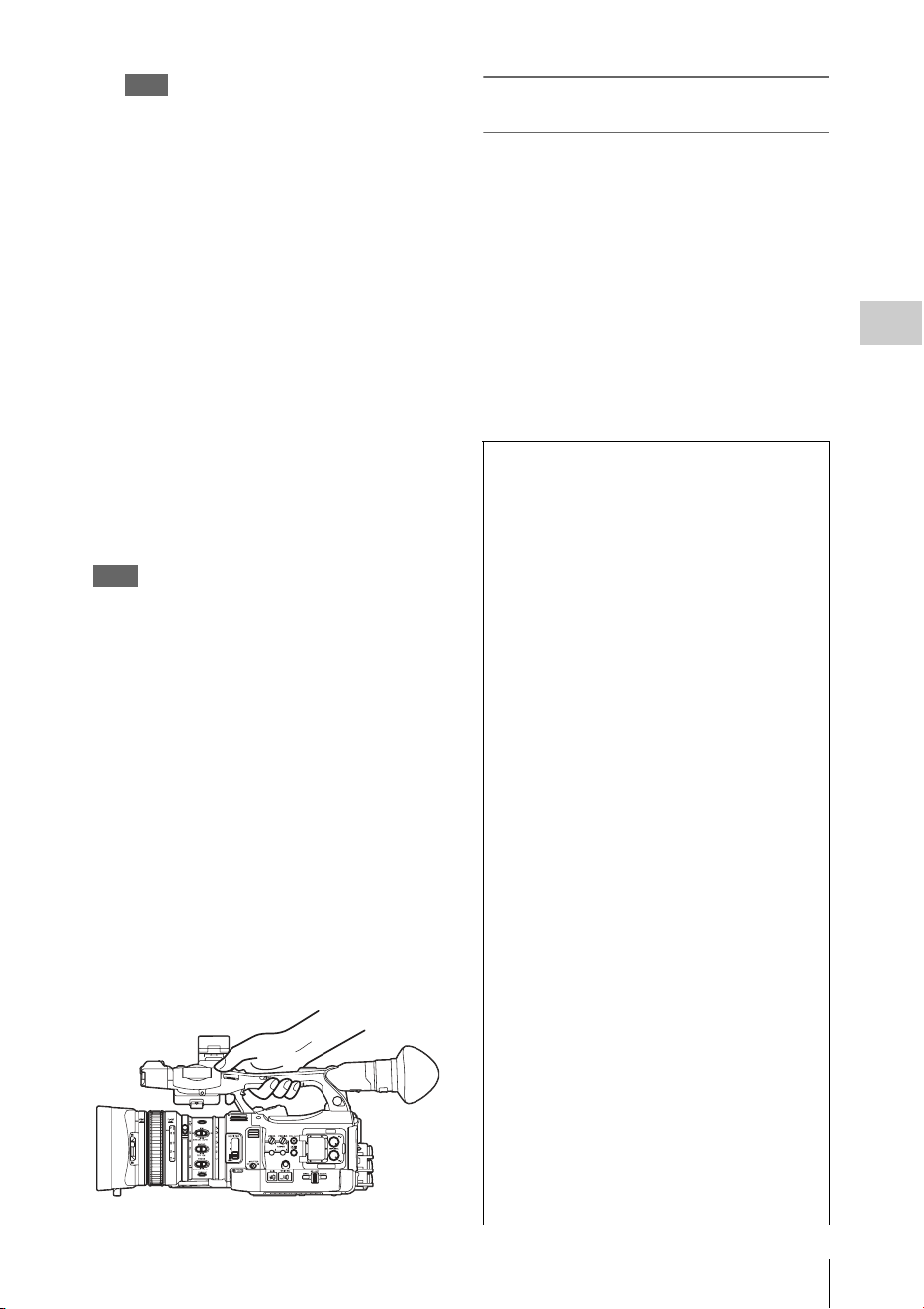
On holding the handle
When shooting by holding the handle, hold the
front end of the handle to keep the camcorder
steady.
Checking the last recorded clip (Rec
Review)
9
Press the REC REVIEW button.
The Rec Review function (page 40) is
activated, and the last recorded clip is played
back for the specified time on the LCD
monitor/EVF screen.
To delete clips
You can delete the last recorded clip by using the
Last Clip DEL function (page 54). Use the All
Clips DEL function (page 54) to delete all
recorded clips from an SxS memory card. To
specify a clip to be deleted, operate the camcorder
from the thumbnail screen (page 88).
Clip (recording data)
When you stop recording, video, audio and
subsidiary data from the start to end of the
recording are recorded as a single clip on an
SxS memory card.
Clip name
For each clip recorded with this camcorder, a
clip name is automatically generated according
to the method selected with “Auto Naming” in
“Clip”
(page 134)
of the OTHERS menu.
The default setting of “Auto Naming” is “Plan.”
With this setting, a clip name defined in
planning metadata is applied if a planning
metadata file is loaded into the camcorder.
Change the “Auto Naming” setting to “Title” to
apply a clip name composed of 4 to 46
alphanumerics and 4 numerics.
Example: ABCD0001
The block of 4 to 46 alphanumerics can be
specified as desired using “Clip” in the
OTHERS menu before you start recording. (It
cannot be changed after recording.)
The value of the 4 numerics is automatically
counted up in sequence.
Notes on Clips
The maximum file size for a clip is 43 GB for
UDF and exFAT, 4 GB for FAT HD Mode, and
2 GB for FAT SD Mode. If you continue
recording for an extended period, recorded
materials may be segmented into multiple files,
depending on the file size (the maximum
number of partitions is 99). The camcorder
regards continuous recording as one clip even if
it has been segmented into multiple files in FAT
mode.

Changing Basic Settings
30
Recording
You can make changes to the settings based on
the intended usage of the recorded video or
recording conditions.
Selectable formats vary depending on the UDF/
exFAT/FAT, HD Mode/SD Mode, and usage
region (NTSC Area/PAL Area) settings.
You can change the usage area by setting “Country”
in “System” (page 133) of the OTHERS menu.
Switching between UDF/exFAT/FAT
Switch by setting “F.Sys.” in “System” (page
133) of the OTHERS menu.
After switching this setting, the camcorder will
automatically restart.
Note
UDF/exFAT/FAT cannot be switched during recording
or playback.
Switching between HD Mode/SD Mode
For HD/SD switching, use “System” (page 133)
of the OTHERS menu.
After switching this setting, the camcorder will
automatically restart.
Note
HD/SD switching is disabled during recording and
playback.
Switching between XAVC/MPEG2
For XAVC/MPEG2 switching, use “System”
(page 133) of the OTHERS menu.
“XAVC/MPEG2” can be selected only when
“F.Sys.” of the OTHERS menu is set to “exFAT”
and “HD/SD” of the OTHERS menu is set to
“HD.”
Note
XAVC/MPEG2 switching is disabled during recording
and playback.
A long clip can be recorded crossing over two
memory cards in slot A and B.
When you copy recorded clips to a hard disk,
etc., via computer, it is recommended to use the
dedicated application software, which you need
to download, to maintain the continuity of
recorded materials. For details, see “Software
Downloads” (page 186).
Note
If copying is done using Explorer (Windows) or
Finder (MAC), the continuity and relationships of
recorded materials may not be maintained.
Maximum duration of a clip
The maximum clip length is 24 hours for FAT
(MP4 or AVI) and 6 hours for UDF (MXF) and
exFAT (MXF).
If you exceed the maximum clip length, a new
clip will be automatically created. You can
check the new clip on the thumbnail screen.
Changing Basic Settings
Video Formats

Changing Basic Settings
31
Recording
Changing the format
To change the format, use “Format” in “System”
(page 133) of the OTHERS menu.
Signals from the SDI OUT, A/V OUT, and HDMI
OUT connectors are also output according to the
format selected with this menu.
ND filters are available for keeping the aperture
in a proper range.
2:
1
/
64
ND
1:
1
/
8
ND
CLEAR: ND filter not used
You can select the adjustment mode according to
the shooting conditions.
Preset mode
The color temperature is adjusted to the preset
value (factory setting: 3200K) in this mode.
Select this mode when there is no time to adjust
the white balance or when you wish to fix the
white balance to the condition of you set for a
Picture Profile.
Memory A mode, Memory B mode
The white balance is adjusted to the value stored
in memory A or memory B.
Pressing the WHITE BAL button executes auto
white balance and stores the adjusted value in
memory A or memory B.
When the Wi-Fi remote commander is used and
the ATW function is set to off, the adjusted value
is changed to the one in memory A, irrespective
of the status of the WHITE BAL switch.
ATW (Auto-Tracing White balance) mode
In this mode, the camcorder automatically adjusts
the white balance to the appropriate condition.
When the color temperature of the light source
changes, the white balance adjustment is
automatically executed.
Five steps of adjustment speed can be selected
with “ATW Speed” (page 113) of the CAMERA
SET menu.
When the ATW Hold function is assigned to an
assignable button (page 40), you can
momentarily hold the ATW value to fix the white
balance, even in ATW mode, by pressing the
button.
Note
Under some conditions of lighting or the shooting
subject, adjustment by ATW may fail to provide proper
colors.
Examples:
• When the subject of a substantially single color like
sky, sea, ground, grass, or certain kinds of flowers
occupies most of the frame area.
• When the subject is under a light source of extremely
high or extremely low color temperature.
If execution of automatic tracing by the ATW function
takes an unacceptably long time or only results in an
inadequate effect, then execute the AWB function.
Using the switch
Make a selection with the WHITE BAL switch
(page 11).
B: ATW mode or Memory B mode
A: Memory A mode
PRST: Preset mode
The B position of the WHITE BAL switch is
assigned to ATW mode at the factory. The setting
can be changed with “White Switch <B>” (page
113) of the CAMERA SET menu to select
Memory B mode.
Setting the camcorder to Full Auto mode (page
28) forcibly activates ATW mode.
Assigning the ATW on/off function to an
assignable button (page 40) permits you to
independently activate/deactivate ATW when
Full Auto mode is off.
Using the Direct menu
When you press the DISPLAY button (page 10),
the current adjustment mode and color
temperature are displayed on the screen (page
14).
AT W: ATW mode
W:A: Memory A mode
W:B: Memory B mode
W:P: Preset mode
When the Direct menu (page 16) is in All mode,
you can select from among ATW, W:A, W:B, and
W:P.
When the Direct menu is in Part mode, you can
switch between ATW and the mode set with the
WHITE BAL switch.
When W:NS is displayed, switching via the
Direct menu is not possible.
ND Filter
White Balance

Changing Basic Settings
32
Recording
Using the assignable button
When recalling one of the picture profiles (PP1 to
PP6, 6 types) that are registered, you can switch
the preset color temperature from 4 types of
presets that are set on “Preset White” in “White”
by pressing the assignable button to which “WB
Preset” is assigned.
To set the preset color temperature
1 Press the PICTURE PROFILE button
(page 11).
The PICTURE PROFILE menu appears.
2 Select “SEL,” and select the picture
profile (PP1 to PP6).
3 Select “SET,” and select the preset
number 1, 2, 3, or 4 on “Preset White
Sel” in “White.”
4 Set the color temperature on “Preset
White” in “White.”
The color temperature of 1, 2, 3, or 4 that is
selected on “Preset White Sel” appears on
“Preset White.”
The default setting of the color temperature
for 1, 2, 3, or 4 that is selected on “Preset
White Sel” is as follows.
• 1 is selected for “Preset White Sel”: 3200K
• 2 is selected for “Preset White Sel”: 4300K
• 3 is selected for “Preset White Sel”: 5600K
• 4 is selected for “Preset White Sel”: 6300K
The color temperature can be set in step of
100K.
5 Press the SEL/SET button or the jog
dial after setting the color temperature.
6 Repeat Steps 3 to 5 to set the color
temperature for other preset number.
To operate by using the assignable button
1 Assign “WB Preset” to one of the
assignable buttons 1 to 5.
2 Select the preset mode by using the
WHITE BAL switch (page 11) or
operating on the Direct menu.
Note
When “Network Remote” is set to “On,” the
adjustment mode for white balance is set to the
Memory A mode and you cannot set to the preset
mode. To set to the preset mode, set “Network
Remote” to “Off.”
3 Press the assignable button to which
“WB Preset” is assigned.
The 4 preset color temperature settings that
are set on “To set the preset color
temperature” (page 32) are switched each
time you press the assignable button.
Note
The preset color temperature cannot be switched in the
following situations.
• When the adjustment mode for white balance is set to
the ATW mode, Memory A mode, or Memory B mode
• When “SEL” of “PICTURE PROFILE” is set to “Off”
• During playback, Rec Review, displaying the
thumbnail screen, displaying the color bars
• While performing ABB, AWB, Multi Matrix > Color
Detection, Color Correction > Area Indication, Skin
Tone Detail > Area Detection, APR, Auto FB, AWS,
or ABS
Executing Auto White Balance
1 To store the adjustment value in
memory, select Memory A or Memory
B mode.
2 Place a white subject under the same
lighting condition and zoom in on it so
that a white area is obtained on the
screen.
3 Adjust the brightness.
Adjust Iris as instructed in “Adjusting the
brightness manually” (page 34) below.
4 Press the WHITE BAL button (page 8).
When you execute the adjustment in a memory
mode, the adjusted value is stored in memory (A
or B) selected in step 1.
When you execute the adjustment in ATW mode,
adjustment in ATW is resumed.
Notes
• Auto white balance adjustment cannot be performed
when in Preset mode.
• If auto white balance adjustment fails, an error
message is displayed on the screen for approximately
3 seconds. If the error message continues to be

Changing Basic Settings
33
Recording
displayed after several attempts, consult your Sony
service representative.
During recording, various markers and zebra
patterns can be inserted into the image on the
LCD monitor/EVF screen.
This does not affect recording signals.
Displaying the Markers
Use “Marker” (page 120) of the LCD/VF SET
menu.
Displaying the Zebra Patterns
A zebra pattern(s) can be inserted to the picture
on LCD monitor/EVF screen to check the
appropriate luminance level.
Pressing the ZEBRA button (ASSIGN 1 button)
(page 11) turns the zebra pattern-indication on/
off.
Changing the zebra pattern
Using “Zebra” (page 120) in the LCD/VF SET
menu, you can change the zebra pattern to be
displayed.
Recording with Fixed Gain
You can change the gain of the video amplifier.
Selecting the gain with the switch
The gain value at each of the GAIN switch (page
11) positions set at the factory are as follows:
L: 0 dB
M: 9 dB
H: 18 dB
These values can be changed in the range of
–3 dB to +18 dB, using the CAMERA SET
menu’s Gain Setup menu (page 108).
Note
You cannot select a fixed gain when AGC mode is set to
On.
Selecting gain using the Direct menu
When you press the DISPLAY button (page 10),
the current gain value is displayed on the screen
(page 14).
When the Direct menu is in All mode, you can
change the gain in steps of 3 dB with the Direct
menu.
You can also select AGC mode with the Direct
menu.
When the Direct menu is in Part mode, you can
switch between only AGC mode and the gain
selected with the GAIN switch.
Recording in AGC Mode
The gain of the video amplifier is automatically
adjusted according to the picture brightness.
When you set the camcorder to Full Auto mode
(page 28), AGC mode is forcibly selected.
When Full Auto mode is off, you can
independently turn AGC mode on by setting
“AGC” in “TLCS” (page 113) of the CAMERA
SET menu to “On,” or selecting “AGC” with the
Direct menu.
Recording with a fixed shutter
Set the shutter speed (cache time).
When you set the SHUTTER switch (page 11) to
ON, the fixed shutter is turned on in the mode and
with the shutter speed you specified with
“Shutter” (page 108) of the CAMERA SET
menu.
Notes
• When Auto Shutter mode is on, the fixed shutter
cannot be selected.
• When the SLS/EX SLS mode (page 34) is on, the fixed
shutter cannot be selected.
Setting with the CAMERA SET menu
The shutter mode and shutter speed can be set
with “Shutter” (page 108) of the CAMERA SET
menu.
Setting with the Direct menu
When you press the DISPLAY button, the current
shutter mode and the set value are displayed
(page 14).
When the Direct menu (page 16) is in All mode,
you can change the shutter mode and speed with
the Direct menu.
Notes
• When the Direct menu is in Part mode, you cannot turn
the shutter off with the Direct menu if the SHUTTER
switch is set to ON.
Markers/Zebra Patterns
Gain
Electronic Shutter

Changing Basic Settings
34
Recording
If the SHUTTER switch is set to OFF, you can switch
only between Auto Shutter and Shutter OFF.
• The Direct menu cannot be selected when Full Auto
mode is turned on (page 28) or when the SLS/EX SLS
mode is set.
Shooting in SLS/EX SLS Mode
The shutter speed is specified in the number of
accumulated frames. Up to 64 frames can be
accumulated in this mode, permitting you to
obtain low-noise clear pictures in low light levels
or surreal pictures with afterimages.
For SLS/EX SLS, specify the number of
accumulated frames with “SLS/EX SLS” (page
108) of the CAMERA SET menu. You can select
from 2 to 8, 16, 32, 64 frames.
When SLS/EX SLS is ON, you cannot set Full
Auto mode (page 28).
When Full Auto mode (page 28) is on or Auto
Shutter mode is on, and SLS/EX SLS is set to on,
Full Auto mode or Auto Shutter mode is
canceled.
Shooting in Auto Shutter Mode
The shutter speed is automatically adjusted
according to the picture brightness.
When you set the camcorder to Full Auto mode
(page 28), Auto Shutter is forcibly selected.
When Full Auto mode is off, you can
independently turn Auto Shutter mode on by
setting “Auto Shutter” in “TLCS” (page 113) of
the CAMERA SET menu to “On.”
Adjust the brightness according to the subject.
Recording in auto mode
When Full Auto mode (page 28) is set to on:
Iris is forcibly set to Auto mode.
When Full Auto mode is set to off:
When the IRIS switch is set to AUTO, Auto Iris
mode is set.
You can select the target level (to make the
picture darker or brighter) for Auto Iris via the
Setup menu or Direct menu. (The gain control in
AGC mode and the shutter speed control in Auto
Shutter mode are adjusted in synchronization.)
To adjust the target level with the Setup menu
Set “Level” in “TLCS” (page 113) of the
CAMERA SET menu.
To adjust the target level with the Direct menu
The target level can also be selected using the
Direct menu (page 16). When you press the
DISPLAY button, the current Exposure position
is displayed on the screen (page 14).
Adjusting the brightness manually
When Full Auto mode is set to off, setting the
IRIS switch to MANUAL sets to Manual Iris
mode. Rotate the iris ring for the desired iris
opening.
Switching to Auto Iris mode temporary
By pressing the assignable button to which “One
Push Auto Iris” is assigned during Manual Iris
mode, the One Push Auto Iris function is
activated. The One Push Auto Iris function is
activated while pressing the button. When the
button is released, the camcorder returns to
Manual Iris mode.
Operating Zoom manually
Setting the ZOOM switch (page 13) on the
bottom of the camcorder to the MANUAL
position sets to manual zoom mode.
Using the Power Zoom
The power zoom lever (page 13) on the grip and
the on-handle ZOOM button (page 10) are
activated.
The supplied IR Remote Commander and
optional lens remote control unit can also be used.
Setting the ZOOM switch on the bottom of the
camcorder to the SERVO position sets to power
zoom mode.
The current zoom position is displayed on the
screen in the range of 0 (Wide) to 99 (Tele) when
you press the DISPLAY button.
The numerical indication can be changed to that
in a bar by changing “Zoom Position” in “Display
On/Off” (page 120) of the LCD/VF SET menu.
To adjust with the power zoom lever on the grip
Pressing the lever deeper sets zooming faster.
To adjust with the on-handle ZOOM button
You can select the zoom speed with “Handle
Zoom” (page 109) of the CAMERA SET menu.
The “Vari” setting enables faster zoom speed the
Iris
Zoom

Changing Basic Settings
35
Recording
deeper the on-handle ZOOM button is pressed as
in the case of the power zoom lever on the grip.
The zoom speed assignment can be changed with
“Zoom Speed” (page 109) of the CAMERA SET
menu.
You can select Soft mode for zooming by using
“Zoom Transition” (page 110) of the CAMERA
SET menu, in which the zooming speed is
gradually increased at the beginning then
gradually decreased for the end.
When adjusting with the ZOOM button of the IR
Remote Commander
The zooming speed depends on the “Remote”
(page 109) setting in “Zoom Speed” of the
CAMERA SET menu.
To use the IR Remote Commander, see “Using the IR
Remote Commander” (page 21).
When using a lens remote controller
Zooming can also be controlled from an optional
lens remote controller connected via the LENS
REMOTE connector.
For operation, refer to the operation guide of the lens
remote controller.
The infinity (∞ ) position has some margin to
compensate for focus change caused by variation
in ambient temperature. When shooting an image
at infinity in MF mode, adjust the focus while
observing the image on the LCD monitor/EVF
screen.
Adjusting in Full MF Mode
Pull the focus ring rearward (toward the
camcorder body) to set the camcorder to Full MF
mode. Focus can only be adjusted with the focus
ring manually.
Note
The focus instantly moves to the range index position
when you pull the focus ring rearward.
Rotate the focus ring for the best focus while
observing the picture on the LCD monitor/EVF
screen.
The range index of the focus ring is effective in
Full MF mode. The distances correspond to the
focus ring positions.
Focus Magnifier
When you press the FOCUS MAG button, the
center area of the picture is magnified on the LCD
monitor/EVF screen, making the focus
adjustment easier.
Press the FOCUS MAG button again or leave the
focus ring unmoved for 5 seconds to resume the
normal angle for recording.
Peaking
When you press the PEAKING button (ASSIGN
2 button), the peaking function is activated. This
function emphasizes the contours of the images
on the LCD monitor/EVF screen, making manual
focusing easier.
This function does not affect recording signals.
The emphasis level and color of the contours can
be set with “Peaking” (page 119) of the LCD/VF
SET menu.
Adjusting in MF Mode
MF (Manual Focus) mode allows you to activate
Auto Focus momentarily when required.
Slide the focus ring forward (to lens hood side),
then set the FOCUS switch (page 11) to
MANUAL.
In this mode, expanded focus function, peaking
function, one-push auto focus function, and the
MF Assist function are activated.
Rotate the focus ring while looking at the LCD
monitor/EVF screen to adjust the focus.
One-Push (Momentary) Auto Focusing
When you press the PUSH AUTO button, auto
focusing momentarily activates. One-Push Auto
Focusing is terminated when the subject comes
into focus.
MF Assist function
If you set “MF Assist” (page 109) of the
CAMERA SET menu to “On” to enable the MF
Assist function, auto focusing is engaged when
you stop rotating the lens operation ring,
performing fine focus adjustment for the subject
in the center of the screen. When the fine
adjustment is completed, automatic focusing with
the MF Assist function is terminated.
You can also enable the MF Assist function via
the Direct menu (page 16). When you press the
DISPLAY button, the selected focus mode is
displayed on the screen (page 14). The Direct
menu cannot be selected in a mode other than MF
mode.
Focus

Changing Basic Settings
36
Recording
Adjusting in AF Mode
AF (Auto Focus) mode adjusts the focus
automatically.
Slide the focus ring forward, then set the FOCUS
switch to AUTO.
Using Macro Mode
When you set the MACRO switch to ON in AF or
MF mode, Macro mode is activated, permitting
you to adjust the focus in a range that includes the
macro area.
The Macro mode is invalid in Full MF mode.
By activating the Steady Shot function, blurring
of images due to camera shaking can be reduced.
Press the STEADY SHOT button on the
lens.
Pressing the button turns the Steady Shot function
on or off.
The setting of the Steady Shot function is
displayed in the EVF screen.
Note
If the camcorder is fixed to a tripod for stable
condition, deactivate the Steady Shot function.
Setting the shutter speed according to
the power-supply frequency
Activate the electronic shutter (page 33) and set
the shutter speed according to the power supply
frequency.
When the frequency is 50 Hz
Set the shutter speed to 1/50 or 1/100 seconds.
When the frequency is 60 Hz
Set the shutter speed to 1/60 or 1/120 seconds.
Using the Flicker-Reduction function
Set “Mode” in “Flicker Reduce” (page 109) of the
CAMERA SET menu to “Auto” or “On” and set
“Frequency” to the power-supply frequency (50
Hz or 60 Hz).
Note
If the frame rate selected for recording is close to the
power-supply frequency, flicker may not be reduced
sufficiently even if you activate the Flicker-Reduction
function. In such cases, use the electronic shutter.
Setting the Timecode
Specify the timecode to be recorded with
“Timecode” and “TC Format” of the TC/UB SET
menu (page 122).
Setting the Users Bit
You can add a hexadecimal number of 8 digits for
pictures as the user bits.
The user bits can also be set to the current date.
Use “Users Bit” (page 122) of the TC/UB SET
menu.
Displaying the Time Data
Pressing the DISPLAY button displays the time
data on the screen (page 14).
The indication is switched among the timecode,
user bits, and recording duration each time you
press the DURATION/TC/U-BIT button (page
10).
Steady Shot
Flickers
Time Data
Display Contents
TCG **:**:**:** Timecode
CLK **:**:**:** Timecode (Clock mode)
UBG ** ** ** ** User bits
DUR **:**:** Duration from the beginning of
recording
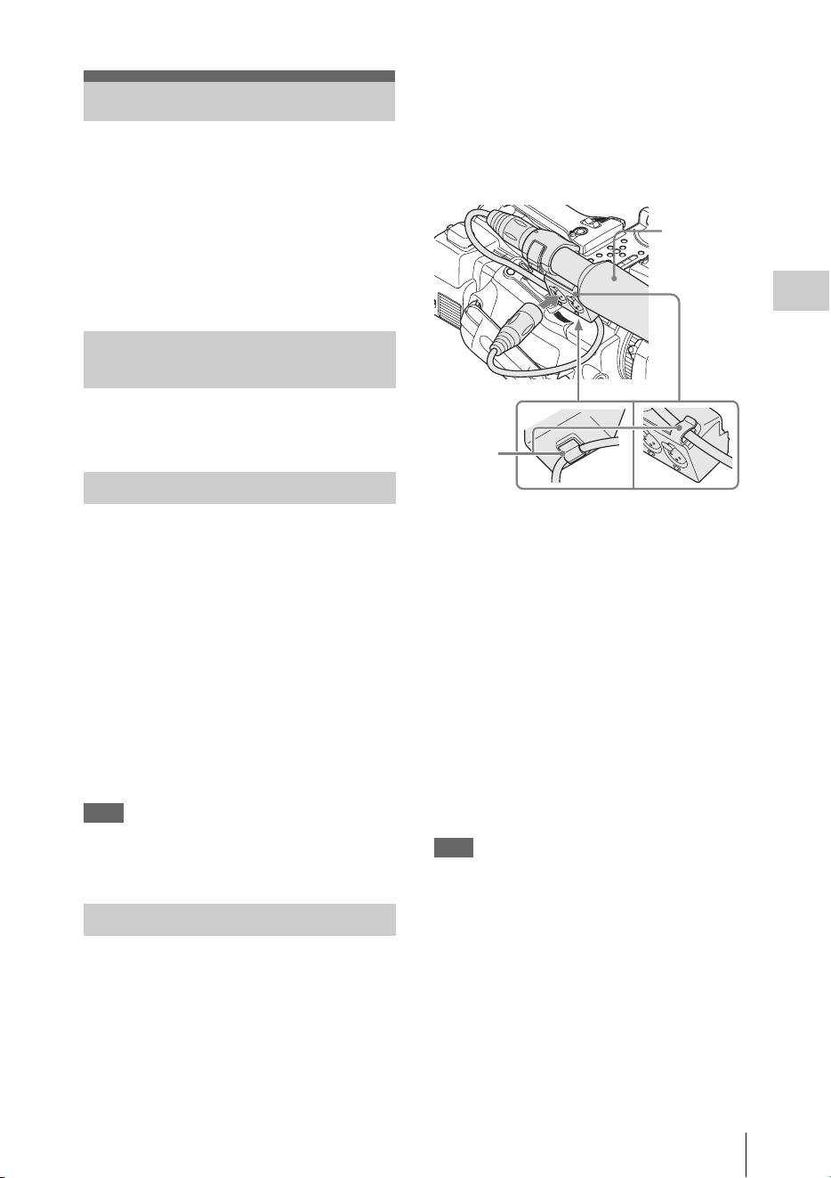
Recording Audio Signals
37
Recording
Four channels (CH-1/CH-2/CH-3/CH-4) of audio
can be recorded (Linear PCM recording) in
synchronization with video recording.
You can use the built-in stereo microphones
(omni-directional electret condenser
microphones) or 2-channel external audio inputs
to the AUDIO IN connectors by switching with
the AUDIO IN switches.
Set the AUDIO IN switches, both CH-1 and
CH-2 (page 11), to INT.
1 Set the CH-1 and CH-2 AUDIO IN
switches (page 11) to EXT.
2 Connect external audio sources to the
AUDIO IN connectors CH-1 and CH-2
(page 9).
3 Set “CH1 EXT Input” and “CH2 EXT
Input” in “Audio Input” of the AUDIO
SET menu to “XLR” (page 115).
4 Set the input (LINE/MIC/MIC+48V)
switches CH-1 and CH-2 (page 9) to
LINE (line level: +4 dBu).
Note
When using XLR input connector, set “CH1 EXT Input”
or “CH2 EXT Input” in “Audio Input” of the AUDIO
SET menu to “XLR”.
You can use an external microphone for
recording, such as the ECM-673 Electret
Condenser Microphone.
1 Lift up the handle of the external
microphone holder (page 9) and open
the cover.
2 Attach a microphone, then return the
external microphone holder cover to its
original position to secure it.
3 Connect the microphone cable to the
AUDIO IN CH-1/CH-2 connectors.
4 Set the corresponding AUDIO IN
switch (CH-1/CH-2) (page 11) to EXT.
5 Set “CH1 EXT Input” and “CH2 EXT
Input” in “Audio Input” of the AUDIO
SET menu to “XLR” (page 115).
6 Set the corresponding input (LINE/
MIC/MIC+48V) switch (CH-1/CH-2)
(page 9) according to the connected
microphone.
MIC: For a microphone that requires no
power supply
MIC +48V: For a microphone that requires
+48V power supply (such as the ECM-
673)
Note
When using XLR input connector, set “CH1 EXT Input”
or “CH2 EXT Input” in “Audio Input” of the AUDIO
SET menu to “XLR”.
Using a microphone compatible with the Multi
Interface Shoe
1 Set the CH-1 and CH-2 AUDIO IN
switches to EXT.
2 Attach a microphone to the Multi
Interface Shoe
Recording Audio Signals
Using the Built-in Stereo
Microphones
Using External Inputs
Using an External Microphone
External
microphone
to AUDIO IN
Cable
clamp

Recording Audio Signals
38
Recording
3 Set “CH1 EXT Input” and “CH2 EXT
Input” in “Audio Input” of the AUDIO
SET menu to “SHOE MIC” (page 115).
Notes
• The action of the Multi Interface Shoe differs
depending on the used power source, AC adaptor (BC-
U1, BC-U2), or the battery pack.
When using the AC adaptor (BC-U1, BC-U2)
—When a Network function is used, no power is
supplied to the Multi Interface Shoe.
—When using the wireless microphone UWP-D11/
D12, set “NW&Proxy/USB” to values other than
“Network&Proxy.”
—Connect the wireless microphone UWP-D11/D12
with the XLR input connector of this unit when
using a Network function and wireless
microphone UWP-D11/D12 simultaneously.
In this case, use the wireless microphone UWP-
D11/D12 with a battery pack as no power is
supplied to the Multi Interface Shoe.
When using a battery pack
—The power is supplied to the Multi Interface Shoe
and the wireless microphone UWP-D11/D12 can
be used.
• When “CH1 EXT Input” and “CH2 EXT Input” in
“Audio Input” of the AUDIO SET menu are set to
“SHOE MIC,” the settings for the CH-1 and CH-2
input (LINE/MIC/MIC+48V) switches are disabled.
Any position is set to equivalent to MIC.
To adjust the levels automatically (AGC)
When the AUDIO SELECT switches CH-1 and
CH-2 (page 11) are set to AUTO, the audio
recording levels are automatically adjusted.
To adjust the levels manually
Set the AUDIO SELECT switches CH-1 and CH-
2 to MANUAL and adjust the audio recording
levels by turning the AUDIO LEVEL knobs
(page 11).
Set the controls to 5 for the reference setting (0
dB). Setting to 10 maximizes the level (+12 dB),
and setting to 0 minimizes it (–∞ ).
The input levels are displayed on the screen when
you press the DISPLAY button (page 14).
Audio recording in special recording
modes
No audio recording is made in Interval Recording
or Frame Recording.
No audio recording is made in Slow & Quick
recording if the recording frame rate is set to a
value different from the playback frame rate.
You can monitor the sounds being recorded with
the headphones connected to the headphone
connector (stereo mini jack) (page 8).
Note
The built-in speaker is disabled during recording (or
when standing by to record).
To adjust the audio monitoring volume
Use the VOLUME buttons (page 10).
Adjusting the Audio Recording
Levels
Monitoring the Audio

Useful Functions
39
Recording
By setting “Camera/Bars” in “Color Bars” (page
109) of the CAMERA SET menu to “Bars,” you
can output a color-bar signal in place of the
camera picture. When this item is set to
“Camera,” the output returns to the camera
picture.
A 1-kHz reference tone is output with the color
bar signal if “1KHz Tone” in “Audio Input” (page
115) of the AUDIO SET menu is set to “On.”
The color-bar signal and reference-tone signal are
also fed out from the SDI OUT, HDMI OUT,
i.LINK, VIDEO OUT (color bars only), and A/V
OUT connectors.
You can select the type of color bars with “Bars
Type” in “Color Bars” of the CAMERA SET
menu.
Notes
• The color bar mode cannot be output in Slow & Quick
Motion mode and SLS/EX SLS mode.
• You cannot switch to “Color Bars” while recording.
(Switching from “Color Bars” to “Camera” is
available.)
When you record shot marks for important scenes
of a clip recorded in UDF, exFAT, or FAT HD
Mode as subsidiary data, you can access the
marked points easily on a Shot Mark screen (page
96), which only displays scenes with shot marks
only. This increases editing efficiency.
The camcorder permits you to record two types of
shot marks: shot mark 1 and shot mark 2.
Shot marks can be recorded as needed during
recording or can be added after recording while
checking the playback pictures on the thumbnail
screen.
Inserting a shot mark during recording
If the Shot Mark1 or Shot Mark2 function is
assigned to an assignable button (page 40), press
the button where you want to insert a shot mark.
For operations to add shot marks after recording,
see “Adding Shot Marks During Playback (UDF,
exFAT, and FAT HD Mode)” on page 91 and
“Adding/Deleting Shot Marks (UDF, exFAT, and
FAT HD Mode)” on page 97.
For operation to apply a name to a shot mark, see
“Defining Shot Mark names in Planning Metadata”
on page 58.
You can add OK/NG/KP flags to clips recorded
with UDF or exFAT. By adding flags, you can set
the camcorder to display only clips with certain
flag settings on the thumbnail screen “OK/NG/
KP/None-Clip thumbnail screen” (page 89).
Note
Use the “Lock Clip” setting (page 92) to protect clips.
Adding a flag
During recording or playback, press the
assignable button to which you assigned the
Clip Flag OK/Clip Flag NG/Clip Flag Keep
function.
You can add an OK/NG/KP flag to a clip during
recording or playback.
Deleting a flag
Press the assignable button, twice in
succession, to which you assigned the Clip
Flag OK/Clip Flag NG/Clip Flag Keep
function.
You can delete the OK/NG/KP flag from a clip.
OK/NG/KP flags can also be added and deleted from
the thumbnail screen. For details, see “Adding/
Deleting a Flag (UDF and exFAT)” (page 94).
By adding the OK mark to a clip recorded in FAT
HD Mode, you can prevent the clip from being
deleted or divided inadvertently. You can also set
the camcorder to display only clips with the OK
Useful Functions
Color Bars/Reference Tone
Shot Marks
OK/NG/KP Flags (UDF and exFAT)
OK Mark (FAT HD Mode Only)
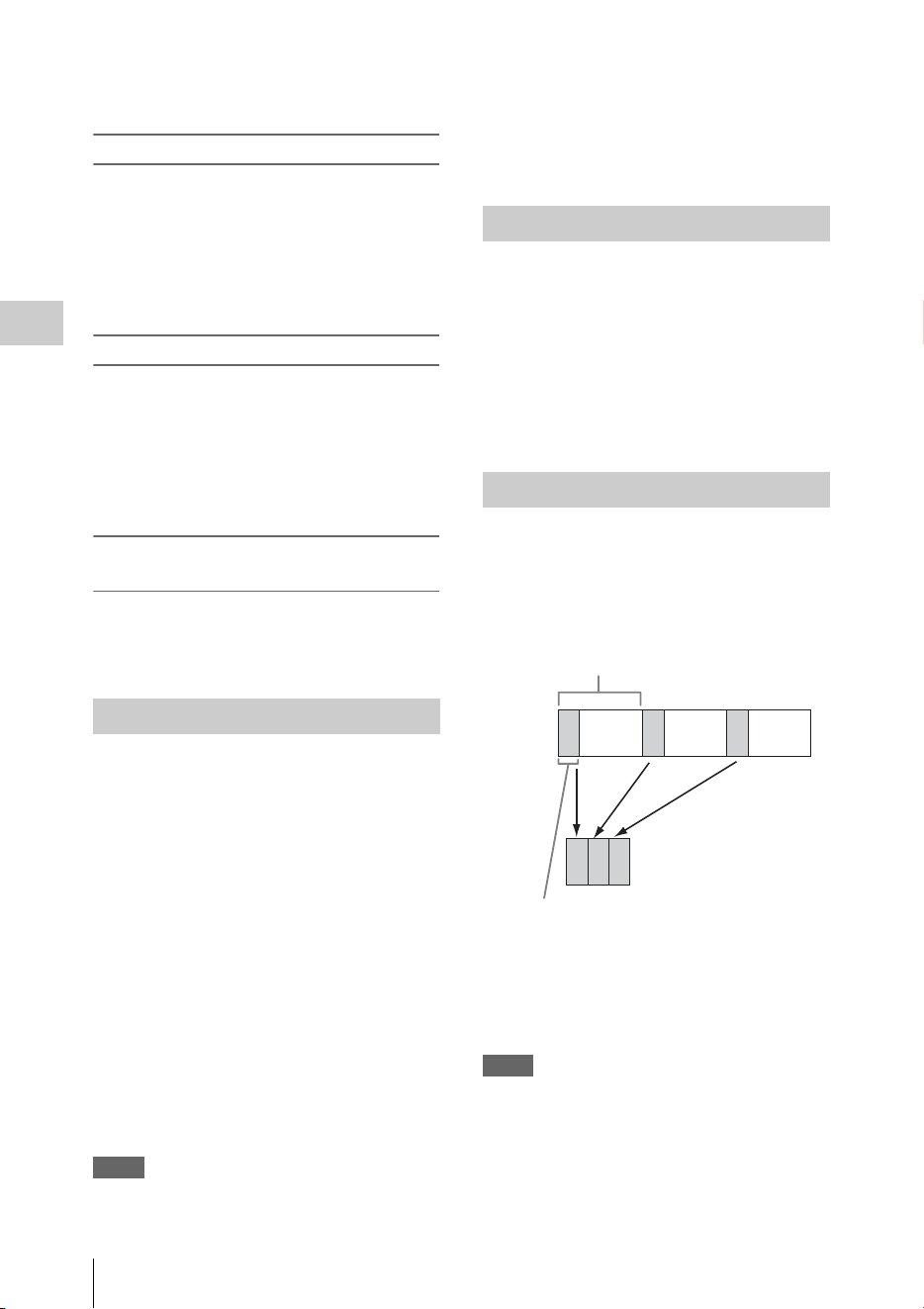
Useful Functions
40
Recording
mark on the thumbnail screen “OK-Clip
thumbnail screen” (page 89).
Adding the OK mark
When recording of a clip ends, press the
assignable button to which you assigned the
OK Mark function.
While standing by to record, you can also add an
OK mark to the last-recorded clip (“Last Clip”)
on the selected memory card.
Deleting the OK mark
Press the assignable button to which you
assigned the OK Mark function, and select
“Execute.”
While standing by to record, you can also delete
the OK mark from the clip with the last-added OK
mark.
Adding or deleting the OK mark to or from
clips before the last one
Make changes via the thumbnail screen.
For details on making settings, see “Adding/Deleting
the OK Mark (FAT HD Mode Only)” (page 94).
You can review the last recorded clip on the
screen (Rec Review).
Press the REC REVIEW button (page 13)
after recording is finished.
If the Rec Review function is assigned to an
assignable button (page 40), you can also use that
button.
The last 3 seconds, 10 seconds, or the entire part
of the clip is displayed, depending on the “Rec
Review” setting (page 113) of the CAMERA
SET menu.
Rec Review is terminated at the end of the clip,
resuming STBY (recording standby) status.
To interrupt Rec Review
Press the REC REVIEW or STOP/CAM button
or the assignable button to which you assigned the
Rec Review function.
Notes
• During Rec Review playback, the playback control
buttons other than the STOP/CAM button are disabled.
• If the video format was changed after recording, Rec
Review cannot be performed (except when the change
was from SP 1440×1080/23.98P to SP 1440×1080/
59.94i).
• The Setup and PICTURE PROFILE menus cannot be
operated during Rec Review.
The camcorder has five assignable buttons (page
11) to which you can assign various functions for
convenience.
To change functions
Use “Assign Button” (page 131) of the OTHERS
menu.
The assigned functions can be viewed on the
“Button/Remote Status Screen” (page 99).
The Interval Recording (time-lapse recording)
function is especially effective for shooting
objects that move very slowly.
The specified number of frames are automatically
recorded at the specified intervals.
It is recommended to fix the camcorder to a tripod
or equivalent and use the IR Remote Commander
to start/stop recording rather than pressing the
REC START/STOP button of the camcorder.
Notes
• Audio cannot be recorded in Interval Recording mode.
• Interval Recording cannot be set to “On”
simultaneously with Frame Recording, Picture Cache
Recording, Slow & Quick Motion, Clip Continuous
Recording, Simultaneous Recording in the 2 slots, or
Proxy Recording. When you set Interval Recording to
“On,” these other functions are forcibly set to “Off.”
Rec Review
Assignable Buttons
Interval Recording
Number of frames for one recording session
(Number of Frames)
Recording interval (Interval Time)

Useful Functions
41
Recording
• Interval Recording mode cannot be used when
“Format” in “System” (page 133) of the OTHERS
menu is set to “HQ 1280×720/23.98P” (in UDF HD
Mode and FAT HD Mode) or “SP 1440×1080/23.98P”
(in FAT HD Mode).
• Interval Recording mode cannot be used when the
items “DVCAM” or “HDV” are set for “SDI/HDMI/
i.LINK I/O Select” (page 117) of the VIDEO SET
menu, and the video format of “Format” in “System”
(page 133) of the OTHERS menu is set to other than
“HQ mode/23.98P.”
Preparatory settings
Before starting Interval Recording, make the
necessary settings of the CAMERA SET menu
(page 110) in advance.
When the video light compatible with the Multi
Interface Shoe is mounted, you can set “Pre-
Lighting” in “Interval Rec” of the CAMERA SET
menu to “On” so that the light turns on
automatically approximately 2 seconds before
recording.
Notes
• While “Pre-Lighting” is set to “On”, the video light
remains on with “Interval Time” set to “3sec” or less,
even if “Rec Link” or “Rec Link + Stby” in “Video
Light Set” is set.
• While “Pre-Lighting” is set to “Off,” the video light
remains off, even if you start recording with “Rec
Link” in “Video Light Set” set. If “Rec Link + Stby” in
“Video Light Set” is set, the video light remains dimly-
lit.
Performing Interval Recording
When the preparatory settings are completed, you
can start recording.
Press the REC START/STOP button.
Notes
• You cannot change the “Interval Time” and “Number
of Frames” settings while Interval Recording is in
progress. To change them, pause recording.
• After starting Interval Recording, Rec Review
operation is disabled, even during an interval.
• The timecode is recorded in Rec Run mode (page 122)
during Interval Recording.
• Some extra frames may be recorded if you stop
recording or switch the card slot while recording is
halted in Interval Recording mode.
• “Setting” for “Interval Rec” is automatically set to
“Off” when you set the power switch to OFF, while the
“Interval Time” and “Number of Frames” settings are
maintained.
The Frame Recording function is especially
effective for clay animation recording.
The specified number of frames are recorded
intermittently when you press the REC START/
STOP button.
It is recommended to fix the camcorder to a tripod
or equivalent and use the IR Remote Commander
to start/stop recording rather than pressing the
REC START/STOP button of the camcorder.
Notes
• Audio cannot be recorded in Frame Recording mode.
• Frame Recording cannot be set to “On” simultaneously
with Interval Recording, Picture Cache Recording,
Slow & Quick Motion, Clip Continuous Recording,
Simultaneous Recording in the 2 slots, or Proxy
Recording. When you set Frame Recording to “On,”
these other functions are forcibly set to “Off.”
• Frame Recording mode cannot be used when “Format”
in “System” (page 133) of the OTHERS menu is set to
“HQ 1280×720/23.98P” (in UDF HD Mode and
exFAT HD Mode) or “SP 1440×1080/23.98P” (in
FAT HD Mode).
• Frame Recording mode cannot be used when the items
“DVCAM” or “HDV” are set for “SDI/HDMI/i.LINK
I/O Select” (page 117) of the VIDEO SET menu, and
the video format of “Format” in “System” (page 133)
of the OTHERS menu is set to other than “HQ mode/
23.98P.”
Preparatory settings
Before starting Frame Recording, make the
necessary settings of the CAMERA SET menu
(page 110) in advance.
Performing Frame Recording
When the preparatory settings are completed, you
can start recording.
1 Press the REC START/STOP button.
When the number of frames you specified
with the menu are recorded, the camcorder
automatically enters FRM STBY (Frame Rec
Standby) status.
2 Press the REC START/STOP button
again.
Each time you press the REC START/STOP
button, the camcorder records the specified
number of frames then enters FRM STBY
status.
Frame Recording

Useful Functions
42
Recording
Notes
• Recording cannot be stopped until the specified
number of frames are recorded. If the power switch is
set to OFF during recording, the power is only shut off
after the specified number of frames are recorded.
• The Rec Review function cannot be used while
recording in Frame Rec mode is in progress.
• You cannot change the “Number of Frames” setting
while recording in Frame Rec mode is in progress. To
change it, pause the recording.
• The timecode is recorded in Rec Run mode (page 122)
during Frame Recording.
• Some extra frames may be recorded if you stop
recording or switch the card slot while recording is
paused in Frame Rec mode.
• “Setting” for “Frame Rec” is automatically set to “Off”
when you set the power switch to OFF, while the
“Number of Frames” setting is maintained.
• When the video light compatible with the Multi
Interface Shoe is mounted, the video light remains off
during recording, even if “Rec Link” in “Video Light
Set” is set. If “Rec Link + Stby” in “Video Light Set”
is set, the video light remains dimly-lit.
Clips are normally created individually for each
time you start and stop recording, but you can also
continue recording to a single clip regardless of
the number of times you start and stop recording
by using the Clip Continuous Recording function,
which will add recordings to the same clip until
the function is disabled or turned off.
This is convenient for when you do not want to
create a large number of short clips, or when you
do not want to be restricted by a maximum
number of clips.
A recording start mark is added to each point at
which you resume recording, making it easy to
search for each point.
Preparatory settings
Before starting Clip Continuous Recording, make
the necessary settings to “Clip Cont. Rec” (page
110) of the CAMERA SET menu in advance.
When you set “Setting” to “On,” the Clip
Continuous Recording function is enabled, and
“CONT” appears on the screen (page 14).
You can also assign “Clip Cont. Rec” to an
assignable button (page 40), and set “Setting” to
“On”/“Off” by pressing the button.
Notes
• Clip Continuous Recording cannot be set to “On”
simultaneously with Picture Cache Recording, Interval
Recording, Frame Recording, Slow & Quick Motion,
Simultaneous Recording in the 2 slots, or Proxy
Recording. When you set Clip Continuous Recording
to “On,” these other functions are forcibly set to “Off.”
• Clip Continuous Recording cannot be used while
recording.
• This function cannot be used with FAT.
Performing Clip Continuous Recording
When the preparatory settings are completed, you
can start recording.
Press the REC START/STOP button.
When recording starts, the “CONT” indication on
the screen changes to “zREC” (with z in red).
Notes
• If you remove the SxS memory card or the battery
while recording or standing by to record (the “CONT”
indication appears), the SxS memory card must be
restored. Only remove the SxS memory card after Clip
Continuous Recording is complete. If “CONT” is
flashing (1 time per second), you can remove the SxS
memory card.
• Record for at least 2 seconds before you stop
recording.
To disable Clip Continuous Recording mode
While standing by to record, set “Setting” in
“Clip Cont. Rec” (page 110) of the CAMERA
SET menu to “Off.”
Restricted Operations
If you perform any of the following operations
while recording or standing by to record, 1
continuous clip will not be created. The next time
you start recording, a new clip will be created.
• Performing clip operations (locking, deleting,
or changing the names of clips).
• Switching the memory card slot.
• Changing the recording format.
• Setting the power switch to OFF.
• Displaying the thumbnail screen.
• Playing clips.
When the Picture Cache Recording function is
active, the camcorder stores the last few seconds
of video captured in the built-in cache memory to
permit you to start recording video on an SxS
memory card from a point before you press the
Clip Continuous Recording (UDF
and exFAT)
Picture Cache Recording:
Retroactively Record

Useful Functions
43
Recording
REC START/STOP button. The maximum
picture cache time is 15 seconds.
Notes
• Picture Cache Recording cannot be set to “On”
simultaneously with Frame Recording, Interval
Recording, Slow & Quick Motion, Clip Continuous
Recording, Simultaneous Recording in the 2 slots, or
Proxy Recording. When you set Picture Cache
Recording to “On,” these functions are forcefully
disabled.
• Picture Cache Recording mode cannot be used while
recording, or while using Recording Review or Freeze
Mix.
• Picture Cache Recording is set to “Off” when you
change any of the settings in “System” (page 133) of
the OTHERS menu.
• When Picture Cache Recording is “On,” the time code
is always recorded in Free Run mode regardless of the
TC/UB SET menu settings (page 122).
• When “Format” in “System” of the OTHERS menu is
set to XAVC-I, the Picture Cache time can be set up to
4 seconds.
Preparatory settings
Before starting Picture Cache Recording, set
“P.Cache Rec” (page 110) of the CAMERA SET
menu.
“Setting” for Picture Cache Recording can also be
set to “On”/“Off” by assigning it to an assignable
button (page 40) and using that button.
When the setting has been made, the special
recording/operation status indication block on the
screen shows “zCACHE,” with z in green
(page 14).
Performing Picture Cache Recording
Press the REC START/STOP button.
Recording begins, and stored video in the cache
memory is written first to the SxS memory card.
The on-screen “zCACHE” indication changes to
“zREC” (z is red).
To cancel the Picture Cache Recording function
Set “Setting” in “P.Cache Rec” of the CAMERA
SET menu to “Off” or press the assignable button
to which you assigned the Picture Cache function.
Notes
• If you change the recording format, the cached data are
cleared and caching is newly started. Therefore, data
cached before you changed the format cannot be
recorded if you start Picture Cache Recording
immediately after changing the format.
• If you start/stop Picture Cache Recording immediately
after you insert an SxS memory card, data may not be
recorded on the card.
• Picture caching starts when you activate the Picture
Cache Recording function. Therefore, video before the
function is activated cannot be recorded with Picture
Cache Recording.
• Picture Cache Recording is invalid for external input
signal (HDV).
• As picture caching is disabled while an SxS memory
card is being accessed, such as during playback, Rec
Review, or thumbnail screen display, Picture Cache
Recording of such a period cannot be made.
• Although you can change the cache time setting while
recording, any new value becomes valid only after
recording has stopped.
• When the video light compatible with the Multi
Interface Shoe is mounted, retroactively recording
before the start of recording is not supported, even if
“Rec Link” or “Rec Link + Stby” in “Video Light Set”
is set. The video light is turned on/off when the REC
START/STOP button is pressed.
When the camcorder is in UDF HD Mode, exFAT
HD Mode, or FAT HD Mode and the video
format (page 133) is set to one of the following
settings, you can set the recording frame rate and
playback frame rate to different values.
NTSC Area
HD422 50/1080/29.97P
HD422 50/1080/23.98P
HD422 50/720/59.94P
HD422 50/720/29.97P
HD422 50/720/23.98P
XAVC-I 1080/29.97P
XAVC-L50 1080/29.97P
XAVC-L35 1080/29.97P
XAVC-I 1080/23.98P
XAVC-L50 1080/23.98P
XAVC-L35 1080/23.98P
XAVC-I 720/59.94P
XAVC-L50 720/59.94P
HQ 1920×1080/29.97P
HQ 1920×1080/23.98P
HQ 1280×720/59.94P
HQ 1280×720/29.97P (FAT HD Mode only)
HQ 1280×720/23.98P (FAT HD Mode only)
PAL Area
HD422 50/1080/25P
HD422 50/720/50P
HD422 50/720/25P
XAVC-I 1080/25P
XAVC-L50 1080/25P
XAVC-L35 1080/25P
XAVC-I 720/50P
XAVC-L50 720/50P
Slow & Quick Motion

Useful Functions
44
Recording
HQ 1920×1080/25P
HQ 1280×720/50P
HQ 1280×720/25P (FAT HD Mode only)
Notes
• Slow & Quick Motion recording cannot be used in SD
Mode.
• Slow & Quick Motion cannot be set to “On”
simultaneously with Frame Recording, Interval
Recording, Picture Cache Recording, Clip Continuous
Recording, Simultaneous Recording in the 2 slots, or
Proxy Recording. When you set Slow & Quick Motion
to “On,” these other functions are forcibly set to “Off.”
• Slow & Quick Motion mode cannot be used while
recording, or while using Recording Review or Freeze
Mix.
• Slow & Quick Motion mode cannot be used when
“SLS/EX SLS” (page 108) of the CAMERA SET
menu is set to other than “OFF.”
• Audio cannot be recorded when the recording and
playback frame rates differ.
Preparatory settings
Before starting Slow & Quick Motion recording,
set “S&Q Motion” (page 111) of the CAMERA
SET menu.
When the special recording mode indication on
the screen is active, “S&Q Motion” is displayed
on the screen (page 14).
Setting the recording frame rate with the Direct
menu
When the special recording mode indication on
the screen is active, [Recording frame rate]/
[Playback frame rate fps] is displayed under
“S&Q Motion.”
You can change the recording frame rate with the
Direct menu (page 16).
Recording in Slow & Quick Motion Mode
When the preparatory settings are completed, you
can start recording.
Press the REC START/STOP button.
Notes
• You cannot change the Frame Rate settings while Slow
& Quick Motion recording is in progress. To change
them, pause the recording.
• The timecode is recorded in Rec Run mode during
Slow & Quick Motion recording (page 122).
• When recording at a low-speed frame rate, it may take
time until recording stops after you press the REC
START/STOP button.
• Slow & Quick Motion mode is automatically set to
“Off” when you set the camcorder’s power switch to
OFF. However, the Frame Rate setting is saved.
Simultaneous recording is available using both
memory card A and B.
Preparatory settings
Before starting Simultaneous Recording in the 2
slots, set “Simul Rec” in the CAMERA SET
menu to “Simul” (page 112).
Notes
• When using Simultaneous Recording in the 2 slots, use
memory cards with the same type and size.
• Using SxS memory cards is recommended.
• SDHC cards are not supported for using Simultaneous
Recording in 2 slots.
Compatible media
SxS PRO+ Series
SxS PRO Series
SxS-1 Series
XQD Memory Card Series
SDXC Card (exFAT Mode only)
Compatible format
When any of the following formats for the exFAT
HD mode is set in “System” of the OTHERS
• XAVC-I
• XAVC-L50
• XAVC-L35
• XAVC-L25
• MPEG2 HD422
• MPEG2 HD420HQ
When any of the following formats for the UDF/
HD mode is set in “System” of the OTHERS
• MPEG2 HD422
• MPEG2 HD420HQ
For details, refer to “Video Format (Format)” (page
150).
Recording in Simultaneous Recording in
the 2 slots mode
When the preparatory settings are completed, you
can start recording.
Press the REC START/STOP button.
The operations of recording start/stop are the
same as those of normal recording.
Simultaneous Recording in the 2
slots

Useful Functions
45
Recording
Notes
• Simultaneous Recording in the 2 slots cannot be set to
“On” simultaneously with the following functions.
—Frame Recording,
—Clip Continuous Recording,
—Picture Cache Recording,
—Slow & Quick Motion,
—Interval Recording
—Proxy Recording
—Network connection (NW&Proxy/USB is set to
Network&Proxy)
—Streaming
• Simultaneous Recording in the 2 slots cannot be set
while recording, playing back or displaying thumbnail
screen.
• When a memory card in one slot becomes full, if a
memory card in the other slot is recordable, recording
continues as normal recording. When you switch the
memory card during continuous recording as normal
recording, simultaneous recording or relay recording is
not available.
• When you start recording with Simultaneous
Recording in the 2 slots, if only one memory card is
inserted in either of slots or one of memory cards is
full, recording starts in a recordable memory card.
In UDF HD Mode, exFAT Mode, or FAT HD
Mode, an image (still picture) of a recorded clip
can be temporarily superimposed on the current
camera picture, permitting you to easily align
images for your next recording.
To use the Freeze Mix function
Assign the Freeze Mix function to one of the
assignable buttons in advance (page 40).
Superimposing a Freeze Mix image
While recording or reviewing images by pressing
the REC REVIEW button, press the ASSIGN
button to which you assigned “Freeze Mix” at the
image with which you want to align. The image is
displayed as a still picture over the current camera
picture.
Canceling Freeze Mix status
You can cancel it with the ASSIGN button to
which you assigned “Freeze Mix” or the REC
START/STOP button.
When you cancel Freeze Mix status by pressing
the ASSIGN button, the normal camera picture is
displayed.
When you cancel Freeze Mix status by pressing
the REC START/STOP button, normal recording
begins.
Notes
• The Freeze Mix function cannot be used in SD Mode.
• Freeze Mix cannot be used when “Format” in
“System” (page 133) of the OTHERS menu is set to
“HQ 1280×720/23.98P” (in UDF HD Mode and
exFAT HD Mode) or “SP 1440×1080/23.98P” (in
FAT HD Mode).
• If the “Format” setting of the recorded picture and the
current camera picture differ, the Freeze Mix display
cannot be achieved.
• The Freeze Mix display cannot be obtained in Slow &
Quick Motion mode or Slow Shutter mode.
• You cannot operate the Setup menus and PICTURE
PROFILE menu in Freeze Mix status.
When automatic adjustment of flange focal
length is activated, focusing is performed both at
the wide-angle and telephoto ends of the zoom for
flange focal length adjustment and the result is
stored so that the in-focus condition is maintained
even if you change the zoom position after
focusing.
Notes
• If a subject of insufficient contrast is used, or if the
camcorder or subject moves during the adjustment,
adjustment cannot be made properly. Once the
adjustment begins, do not touch the camcorder body or
lens until it ends.
• Set “SLS/EX SLS” of the CAMERA SET menu to
“OFF” before starting the adjustment.
• Be careful that no light source, such as a lamp, the sun,
or a bright window, is in field of view during flange
focal length adjustment.
• Contact your dealer if a flange focal length adjustment
chart is required.
1 Set the power switch to ON.
2 Set the ND FILTER switch to CLEAR.
3 Place a high-contrast subject, such as a
flange focal length adjustment chart,
about 3 m (10 ft.) away from the
camcorder, and light it well enough to
provide a sufficient video output level.
Freeze Mix: Image Alignment
Automatic Adjustment of Flange
Focal Length

Useful Functions
46
Recording
Frame the subject so that it is located in the
center at the telephoto end of the zoom. Make
sure that any object located closer to the lens
than the subject is out of frame at the wide-
angle end.
4 Set the ZOOM switch on the bottom of
the camcorder to SERVO (Power Zoom
mode).
5 Set “Auto FB Adjust” of the CAMERA
SET menu to “Execute” in the setup
menu, then press the SEL/SET button
or the jog dial.
The adjustment begins.
During adjustment, the in-progress message
is displayed.
When the adjustment finished, the
completion message is displayed.
Notes
• “Auto FB Adjust” cannot be selected when the ND
filter is set to 1 or 2.
• Do not change the ND filter while “Auto FB Adjust” is
in operation.
If you press the CANCEL button during
adjustment
Automatic adjustment of the flange focal length is
aborted and the condition before starting the
adjustment is resumed.
If the adjustment fails
An error message is displayed.
Check the conditions of the subject and lighting
then perform the adjustment again.
You can customize the picture quality, depending
on the conditions or circumstances of recording,
and store settings as a picture profile, enabling
you to recall the profile as necessary.
Six different picture profiles (PP1 to PP6) can be
stored in memory.
The same standard (reference) values are
registered to six picture profiles at the factory as
those specified for the Picture Profile Off status.
Note
Picture profiles can be set while recording or standing by
to record. They cannot be operated from the thumbnail
screen.
Registering the customized settings as a
Picture Profile
1
Set the power switch (page 8) to ON to
turn on the camcorder.
2 Press the PICTURE PROFILE button
(page 11).
The PICTURE PROFILE menu is displayed.
3 Using the up/down/left/right buttons or
the jog dial, select “SEL,” then press the
SEL/SET button or the jog dial.
4 Select the number of the picture profile
to register from the list, then press the
SEL/SET button or the jog dial.
5 Use the up/down buttons or the jog dial
to select “SET,” then press the SEL/
SET button or the jog dial.
6 Make each setting (page 47).
7 When the settings have been made,
press the PICTURE PROFILE button.
Selecting a registered Picture Profile
Once you store a picture profile, you can recall
the picture quality registered in the picture
profile.
1 While standing by to record, press the
PICTURE PROFILE button (page 11).
The PICTURE PROFILE menu is displayed.
2 Using the up/down/left/right buttons or
the jog dial, select “SEL,” then press the
SEL/SET button or the jog dial.
3 Select the number of the picture profile
to use from the list, then press the SEL/
SET button or the jog dial.
If OFF is selected, the picture quality is set to
standard and cannot be changed.
4 Press the PICTURE PROFILE button.
The picture profile being selected is displayed
when you press the DISPLAY button (page 14).
You can also select picture profiles with the
Direct menu (page 16).
Picture Profiles
Useful Functions
47
Recording
Picture Profile Items
The values when “Off” is selected at “SEL” of the PICTURE PROFILE menu are shown in bold face
(example: Standard).
PICTURE PROFILE SET
Items Subitems and setting values Contents
Profile Name
Changing the picture profile
name
Profile name
Standard
Set the profile name in 8 characters at maximum.
You can use upper- and lowercase alphabetics,
numerics 0 to 9, - (hyphen), _ (underscore) and
space.
Matrix
Adjusting the color phase
over the entire area with
matrix operations
Setting
On / Off
Set to “On” to activate the color phase adjustment
function with matrix operations for the entire
picture.
Notes
• When this function is set to “Off,” Multi Matrix is
also set to “Off” in synchronization.
• If color saturation occurs under lighting that
contains excessive blue components (such as blue
LED lighting), set the “Setting” of “Matrix” to
“Off” to reduce the color saturation.
Select
1 / 2 / 3 / 4 / 5 / 6
Select the built-in preset matrix provided for
convenience.
1: Equivalent to SMPTE-240M / 2: Equivalent to
ITU-709 / 3: Equivalent to SMPTE WIDE / 4:
Equivalent to NTSC / 5: Equivalent to EBU / 6:
Equivalent to PAL
Level
–99 to +99 (±0)
Adjust the color saturation for the entire picture
area.
Phase
–99 to +99 (±0)
Adjust the hue for the entire picture area.
R-G, R-B, G-R, G-B, B-R, B-G
–99 to +99 (±0)
Finely adjust the color phase for the entire picture
area by independently setting each of the factors.
Multi Matrix mode
Selecting multi-matrix
correction and color phase
adjustment for the specified
area
Multi Matrix / Color Correction Select the setting items of the Multi Matrix or the
setting items of the Color Correction.

Useful Functions
48
Recording
Multi Matrix
Makes settings related to
multi-matrix correction.
(Unselectable when “Color
Correction” is selected in the
Multi Matrix mode)
Setting
On / Off
Set to “On” to enable the multi-matrix correction,
which allows specific colors to be selected for
saturation correction in a 16-axis hue space.
Area Indication
1)
On / Off
Set to “On” to display a zebra pattern in the areas of
the specified color for multi-matrix correction.
Color Detection
2)
Execute/Cancel
Execute to detect the target color on the screen for
multi-matrix correction.
Preset
Execute/Cancel
Execute to return the “Hue” and “Saturation”
setting in “Multi Matrix” to the preset value.
Axis
B / B+ /MG- / MG / MG+ / R /
R+ / YL- / YL /YL+ / G- / G /
G+ / CY / CY+ / B-
Specify a color targeted by multi-matrix correction
(16-axis mode).
Hue
–99 to +99 (±0)
Set the the hue of the color targeted by multi-matrix
correction for each 16-axis mode.
Saturation
–99 to +99 (±0)
Adjust the saturation of the color targeted by multi-
matrix correction for each 16-axis mode.
Color Correction
Adjusting the color phase in
a specific area (Unselectable
when “Multi Matrix” is
selected in the Multi Matrix
mode)
Setting
On / Off
Set to “On” to enable the color phase adjustment
for a specific area. (Simultaneous adjustment of
multiple areas is not allowed. You can adjust it for
one area only.)
Area Detection
2)
Execute/Cancel
Execute to detect the color in the center of the
screen. The area centering around the detected
color of the range specified by “Target Width”
becomes the target area of Color Correction.
Area Indication
1)
On / Off
Set to “On” to display the Zebra 1 pattern for the
area targeted for Color Correction.
Note
The area where the Zebra 1 pattern is displayed and
the area targeted for Color Correction, may differ.
Target Phase
0 to 359 (130)
Manually adjust the center color for the area
targeted for Color Correction.
Note
When Area Detection is executed, this setting is
overwritten by the Area Detection result. Perform
fine adjustment with this item as required.
Target Width
0 to 90 (40)
Set the width of color phase for the area targeted for
Color Correction.
Level
–99 to +99 (±0)
Set the saturation for the color in the target area.
Phase
–99 to +99 (±0)
Adjust the hue for the color in the target area.
PICTURE PROFILE SET
Items Subitems and setting values Contents

Useful Functions
49
Recording
White
Setting the white balance
offset and the color
temperature of the preset
white
Offset White
On / Off
Set to “On” to shift the conversion value for auto
white balance in Memory A or B mode and that for
auto tracing white in ATW mode to a lower color
temperature or a higher color temperature.
Offset<A>
–99 to +99 (±0)
Adjust the volume of the offset white (shifting
volumes) of the conversion value in Memory A,
Memory B, or ATW mode, respectively.
Offset<B>
–99 to +99 (±0)
Offset<ATW>
–99 to +99 (±0)
Preset White Sel
1 / 2 / 3 / 4
Select the preset color temperature from the preset
1 to 4 when the adjustment mode for white balance
is set to the preset mode.
Preset White
2100 to 10000
(3200: When “1” is selected for
“Preset White Sel”)
(4300: When “2” is selected for
“Preset White Sel”)
(5600: When “3” is selected for
“Preset White Sel”)
(6300: When “4” is selected for
“Preset White Sel”)
Adjust the color temperature for the preset 1 to 4
that is selected on “Preset White Sel” in steps of
100K.
Notes
• Except when the white balance is in Memory A
or B mode or when ATW is active, you cannot
confirm the result of changing the Offset White
and Offset settings on the screen.
• Except when Preset white balance mode is
selected, you cannot confirm the result of
changing the Preset White settings on the screen.
• When “Network Remote” (page 125) is set to
“On,” the adjustment mode for white balance is
fixed to the Memory A mode regardless of the
position of the WHITE BAL switch.
PICTURE PROFILE SET
Items Subitems and setting values Contents

Useful Functions
50
Recording
HD Detail
Adjusting the details to be
applied to the picture in HD
Mode
Setting
On / Off
Set to “On” to apply the details to the video signal.
Level
–99 to +99 (±0)
Adjust the detail level.
Frequency
–99 to +99 (±0)
Set the center frequency of the details.
Setting the center frequency higher decreases the
details, and setting it lower increases the details.
Crispening
–99 to +99 (±0)
Adjust the noise-suppression level.
When you set it to a higher level, less noise may be
seen, as fine elements of details are deleted leaving
only high-level elements.
When you set it to a lower level, fine elements are
applied while increasing noise.
H/V Ratio
–99 to +99 (±0)
Adjust the horizontal-to-vertical ratio of detail
elements.
A higher value makes the vertical elements
increased with respect to the horizontal elements.
White Limiter
–99 to +99 (±0)
Limit the white details.
Black Limiter
–99 to +99 (±0)
Limit the black details.
V DTL Creation
NAM / Y / G / G+R
Select the source signal to generate vertical details from
among NAM (G or R whichever is higher), Y, G, and G+R.
Knee APT Level
–99 to +99 (±0)
Adjust the knee aperture level (level of details to be
applied to the sections above the knee point).
SD Detail
Adjusting the details to be
applied to the picture in SD
Mode
Setting
On / Off
Set to “On” to apply the details to the video signal.
Level
–99 to +99 (±0)
Adjust the detail level.
Frequency
–99 to +99 (±0)
Set the center frequency of the details.
Setting the center frequency higher decreases the
details, and setting it lower increases the details.
Crispening
–99 to +99 (±0)
Adjust the noise-suppression level.
When you set it to a higher level, less noise may be
seen, as fine elements of details are deleted leaving
only high-level elements.When you set it to a lower
level, fine elements are applied while increasing noise.
H/V Ratio
–99 to +99 (±0)
Adjust the horizontal-to-vertical ratio of detail
elements.
A higher value makes the vertical elements
increased with respect to the horizontal elements.
White Limiter
–99 to +99 (±0)
Limit the white details.
Black Limiter
–99 to +99 (±0)
Limit the black details.
V DTL Creation
NAM / Y / G / G+R
Select the source signal to generate vertical details
from among NAM (G or R whichever is higher), Y,
G, and G+R.
Knee APT Level
–99 to +99 (±0)
Adjust the knee aperture level (level of details to be
applied to the sections above the knee point).
PICTURE PROFILE SET
Items Subitems and setting values Contents
Useful Functions
51
Recording
Skin Tone Detail
Adjusting the details to be
applied to the areas of a
specific color phase
Setting
On / Off
Set to “On” to enable the detail level adjustment for
specific color-phase areas.
The detail level is uniform over the entire picture
with the Off setting.
Level
–99 to +99 (±0)
Adjust the skin-tone detail level.
Area Detection
2)
Execute/Cancel
Select “Execute” to detect the color in the center of
the screen. The area centering on the detected color
becomes the target area for Skin Tone Detail
control.
Area Indication
1)
On / Off
Set to “On” to display the Zebra 1 pattern for the
target area for Skin Tone Detail control.
Saturation
–99 to +99 (±0)
Adjust the color (saturation) level for Skin Tone
Detail control.
Note
When Area Detection is executed, this setting is
automatically returned to 0.
Phase
0 to 359 (130)
Adjust the center color-phase value for the target
area for Skin Tone Detail control.
Note
When Area Detection is executed, this setting is
automatically changed to the value equivalent to
that of the detected color.
Width
0 to 90 (40)
Adjust the width of the color phase of the target
area for Skin Tone Detail control.
Note
When Area Detection is executed, the Width
setting automatically returns to 40.
Aperture
Making settings related to
aperture correction
Setting
On / Off
Set to “On” to enable aperture correction
(processing to improve resolution by adding high-
frequency aperture signals to the video signal,
which corrects degeneration due to high-frequency
characteristics).
Level
–99 to +99 (±0)
Select the level for the aperture correction.
PICTURE PROFILE SET
Items Subitems and setting values Contents

Useful Functions
52
Recording
Knee
Adjusting the knee level
Setting
On / Off
Set to “On” to compress the high-luminance area of
the picture.
Notes
Knee is fixed and cannot be changed in the
following cases:
• When Gamma is set to HG1 to 4
• When the electronic shutter is in slow shutter
mode
• When EX SLS is active
Auto Knee
On / Off
Set to “On” to automatically set the best knee
conditions according to the luminance level of the
picture.
With “Off” the knee conditions can be manually
adjusted independently of the luminance level of
the picture.
Point
50 to 109 (90)
Set the knee point when Auto Knee is “Off.”
Slope
–99 to +99 (±0)
Set the knee slope (volume of compression) when
Auto Knee is “Off.”
Knee SAT
On / Off
Set to “On” to enable the knee saturation
adjustment (level for the area over the knee point).
Knee SAT Level
–99 to +99 (±0)
Adjust the knee saturation level for the area over
the knee point.
White Clip
Setting
On / Off
Turns white clipping adjustment on or off.
Level
When “Country” is set to other
than “PAL Area”
90.0%~109.0% (108.0%)
When “Country” is set to “PAL
Area”
90.0%~109.0% (105.0%)
Specifies the white clip level.
Gamma
Adjusting the gamma
compensation level and
selecting the gamma curve
Level
–99 to +99 (±0)
Adjust the gamma compensation level.
Select
3)
STD1 to STD6 / HG1 to HG4
(HD: STD5, SD: STD4)
Select the type of reference curve for gamma
compensation.
Black
Adjusting the black
–99 to +99 (±0) Adjust the master black level.
Black Gamma
Adjusting the black gamma
level
–99 to +99 (HD: ±0, SD: -16) Adjust the level of black gamma function that
emphasizes only the dark areas of the picture to
clear the tones or on the contrary de-emphasizes it
to reduce noise.
Low Key SAT
Adjusting the low key
saturation
–99 to +99 (±0) Adjust the level of the low key saturation to
heighten the colors only in the dark areas of the
picture or pale them to reduce noise.
Copy
Copying a picture profile
Execute / Cancel Select “Execute” to copy.
PICTURE PROFILE SET
Items Subitems and setting values Contents

Useful Functions
53
Recording
1)The Area Indication “On”/“Off” setting is common to
all picture profiles PP1 to PP6.
2)To execute “Color Detection” of “Multi Matrix” or
“Area Detection” of “Color Correction”/”Skin Tone
Detail”
1. Select “Color Detection” or “Area
Detection.”
A square marker that indicates the detection
area appears in the center of the screen, and
“Execute” and “Cancel” are displayed below.
2. Select “Execute.”
Color-phase detection in the marker area is
performed.
When detection successfully ends, a
completion message is displayed then the
screen is restored.
With Multi Matrix, the target color of multi-
matrix correction is changed to the color
detected by “Color Detection,” and the Area
Indication (zebra pattern) appears on the
screen.
With Skin Tone Detail, the target area for the
adjustment is changed to the area centering
around the color detected by “Area
Detection,” and the Area Indication (zebra
pattern) appears on the screen.
If detection fails, an error message appears,
then the precious screen is restored.
3)Available gamma curves from “Select” in “Gamma”
(STD: Standard gamma, HG: Hyper gamma)
STD1: A gamma table equivalent to an SD camcorder.
STD2: A gamma table with ×4.5 gain.
STD3: A gamma table with ×3.5 gain.
STD4: A gamma table equivalent to the SMPTE-240M
standard.
STD5: A gamma table equivalent to the ITU-R709
standard.
STD6: A gamma table with ×5.0 gain.
HG1: A gamma table for turning 325% D-range input
into 100% output.
HG2: A gamma table for turning 460% D-range input
into 100% output.
HG3: A gamma table for turning 325% D-range input
into 109% output.
HG4: A gamma table for turning 460% D-range input
into 109% output.
PP Data
Writing/loading a picture
profile
Display Mode
Date&Time / Model Name
Select the displayed item on the list box that
appears when storing or loading.
Store(SxS)
Execute / Cancel
Select “Execute” to store a picture profile on an
SxS memory card (up to 64 files can be stored).
Recall(SxS)
Execute / Cancel
Select “Execute” to load a picture profile from an
SxS memory card.
Store(USB)
Execute / Cancel
Select “Execute” to store a picture profile on a USB
flash drive (up to 64 files can be stored).
Recall(USB)
Execute / Cancel
Select “Execute” to load a picture profile from a
USB flash drive.
Reset
Resetting a picture profile
Execute / Cancel Select “Execute” to reset.
PICTURE PROFILE SET
Items Subitems and setting values Contents

Useful Functions
54
Recording
While standing by to record, the Last Clip DEL
function for deleting the last recorded clip and the
All Clips DEL function for deleting all clips from
an SxS memory card are available.
For clip deletion on the thumbnail screen, see
“Deleting Clips” on page 95.
To delete using the assignable button
Assign the Last Clip DEL function to one of the
assignable buttons (page 40) in advance.
Press the assignable button to which you have
assigned “Last Clip DEL,” and select “Execute”
to delete the last recorded clip from the SxS
memory card.
To delete using the Setup menu
Select “Last Clip DEL” in “Clip” (page 134) of
the OTHERS menu, select “Execute,” then select
“Execute” again to delete the last recorded clip
from the SxS memory card.
Note
When Clip Continuous Recording is set to “On,” “Last
Clip DEL” cannot be selected.
Deleting clips collectively
Select “All Clips DEL” in “Clip” (page 134) of
the OTHERS menu, select “Execute,” then select
“Execute” again to delete all the clips from the
SxS memory card.
Notes
• If the SxS memory card contains clips of both of HD
Mode and SD Mode, only the clips of the currently
selected mode are deleted.
• Clips with the OK mark (page 39) cannot be deleted if
FAT is selected for the file system. If UDF or exFAT
is selected, clips set to “Lock Clip” (page 92) cannot be
deleted.
You can store the setup menu settings on an SxS
memory card or a USB flash drive (for UDF or
exFAT Mode).
By using the stored file, the proper setup
condition can be immediately obtained.
Note
Values for “Clock Set” and “Hours Meter” of the
OTHERS menu are not stored.
Setup file
All the menu settings (including picture profiles)
are stored.
Up to 64 files can be stored on an SxS memory
card or a USB flash drive (for UDF or exFAT
Mode).
The setup files are stored using the file name
“SETUP.SUF,” “SETUP002.SUF” -
“SETUP064.SUF.”
User file
The customized setting items of the USER menu
and setting data are stored.
Up to 64 files can be stored on an SxS memory
card or a USB flash drive (for UDF or exFAT
Mode).
By retrieving the file, you can set the USER menu
to the customized setup condition.
The user files are stored using the file name
“001.USER” - “064USER.”
Picture profile
The setting values of the picture profile that are
set for the imaged scene are stored.
Up to 5 files can be stored on an internal memory
of the camcorder. Up to 64 files can be stored on
an SxS memory card or a USB flash drive (for
UDF or exFAT Mode).
The picture profiles are stored using the file name
“PPDATA.SUF,” “PPDATA002.SUF” -
“PPDATA064.SUF.”
Storing the file
1 Prepare the media for storing the files.
To use an SxS memory card
Insert an SxS memory card to a card slot.
Check that the corresponding memory card
icon is displayed on the screen. If a memory
card in another slot is selected, press the
SLOT SELECT button to switch.
To use a USB flash drive
When using a USB flash drive (for UDF or
exFAT Mode), connect the formatted USB
flash drive to the external device connector
(page 26).
2 For the setup files, select “Camera
Data” (page 129) of the OTHERS menu.
Deleting Clips
Storing/Retrieving the Setting
Data

Useful Functions
55
Recording
Select “User Data” (page 129) of the
OTHERS menu for the User file.
Select “PP Data” (page 53) of the PICTURE
PROFILE menu for the picture profile.
To name the stored file
Name the stored file before proceeding to
step 3.
For details, see “Naming the stored file”
(page 55).
3 For the setup files, select “Store(SxS)”
or “Store(USB)” in “Camera Data.”
Select “Store(SxS)” or “Store(USB)” in
“User Data” for the User file.
Select “Store(SxS)” or “Store(USB)” in “PP
Data” for the picture profile.
The list box of the files appears.
“No File” is displayed on the file number for
which no files are stored.
Date, time, and file name are displayed on the
file number for which a file is stored.
4 Select the file number to be stored the
file, then press the SEL/SET button or
the jog dial.
A waiting message is displayed.
Note
If a setup file already exists on the memory card you
stored in step 3, a message to confirm whether to
overwrite the file is displayed.
5 To execute storing, select “Execute,”
then press the SEL/SET button or the
jog dial.
To cancel storing, select “Cancel,” then
press the SEL/SET button or the jog
dial.
When executing storing, an in-progress
message is displayed while writing. When
writing is completed, a completion message
is displayed.
Note
If the writable media is not inserted or there is not
sufficient space on the media, an error message is
displayed.
Naming the stored file
It is useful for identifying a file to name the stored
file before storing the setting data as the file.
The following characters can be used for naming.
Numbers, alphabets, special characters (! # $ % &
‘ ( ) * + , - . / : ; < = > ? @ [ \ ] ~)
Note
Characters that can be used for naming the picture profile
are numbers, alphabets, - (hyphen), _ (underscore), and
space.
1 Select “File ID” in “Camera Data” of
the OTHERS menu.
Select “File ID” in “User Data” of the
OTHERS menu for the User file.
Select “Profile Name” of the PICTURE
PROFILE menu for the picture profile.
2 Select the character by using the jog
dial or the up/down buttons, then press
the SEL/SET button or the jog dial.
3 Repeat step 2.
4 After finishing character input, move
the cursor to SEL by using the SEL/
SET button or the jog dial, then press
the SEL/SET button or the jog dial.
The input name is displayed. When
performing the storing operation for the setup
file (page 54), the data is stored with the
input name.
Retrieving the file
Note
If the stored file on an SxS memory or USB flash drive
(for UDF or exFAT Mode) is retrieved, the setup data
that is stored on the internal memory of the camcorder is
overwritten.
1 Prepare the media for storing the files.
To use an SxS memory card
Insert an SxS memory card in which the file
is stored to a card slot.
Check that the corresponding memory card
icon is displayed on the screen. If a memory
card in another slot is selected, press the
SLOT SELECT button to switch.
To use a USB flash drive
Connect the USB flash drive in which the file
is stored to the external device connector.
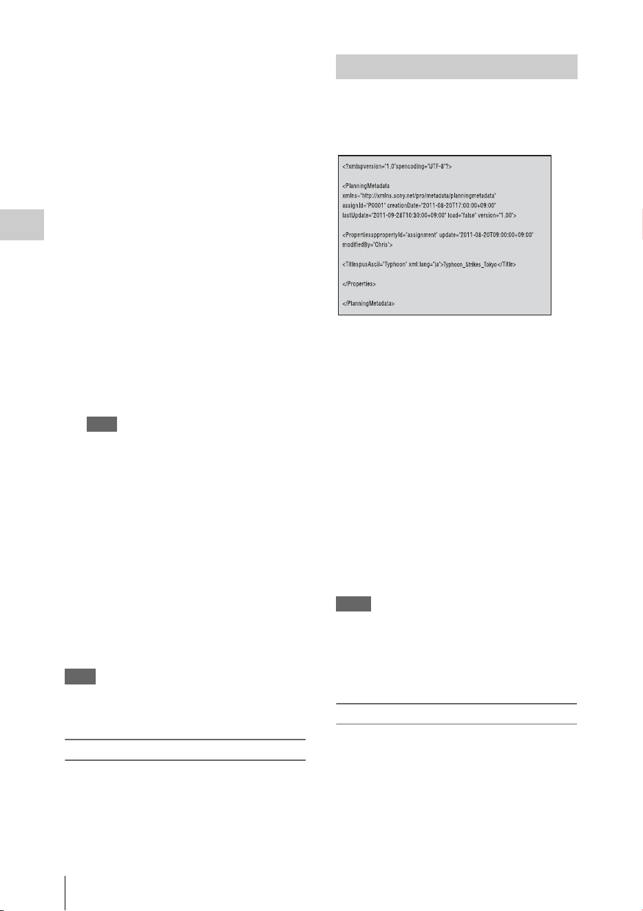
Useful Functions
56
Recording
2 For the setup files, select “Camera
Data” (page 129) of the OTHERS menu.
Select “User Data” (page 129) of the
OTHERS menu for the User file.
Select “PP Data” (page 53) of the PICTURE
PROFILE menu for the picture profile.
3 For the setup files, select “Recall(SxS)”
or “Recall(USB)” in “Camera Data.”
Select “Recall(SxS)” or “Recall(USB)” in
“User Data” for the User file.
Select “Recall(SxS)” or “Recall(USB)” in
“PP Data” for the picture profile.
The list box of the files appears.
“No File” is displayed on the file number for
which no files are stored.
Date, time, and file name are displayed on the
file number for which a file is stored.
4 Select the file number to be recalled,
then press the SEL/SET button or the
jog dial.
A waiting message is displayed.
Note
If the selected file includes a setting change that
needs to restart the camcorder, the message for
permission to restart is displayed.
5 To execute recalling, select “Execute,”
then press the SEL/SET button or the
jog dial.
To cancel recalling, select “Cancel,”
then press the SEL/SET button or the
jog dial.
When executing recalling, an in-progress
message is displayed while recalling. When
recalling is completed, a completion message
is displayed and the setting of the camcorder
is changed to the recalled setting.
Note
If the readable media is not inserted or there is not a
corresponding file on the media, an error message is
displayed.
Resetting to the standard values
The current camcorder settings you made through
various menu and button operations can be
collectively returned to the standard statuses
(factory settings) by executing “All Reset” of the
OTHERS menu.
Planning metadata is information about shooting
and recording plans, recorded in an XML file.
Example of a planning metadata file
You can shoot using clip names and shot mark
names defined in advance in a planning metadata
file.
This camcorder can display clip names and shot
mark names defined in the following languages:
•English
• Chinese
•German
• French
•Italian
• Spanish
•Dutch
• Portuguese
• Swedish
• Norwegian
•Danish
•Finnish
Notes
• If you define clip and shot mark names in languages
other than those listed above, they may not be
displayed on the LCD monitor/EVF screen.
• If you define clip and shot mark names in French,
Dutch, or Finnish, some characters are displayed in a
different but similar font.
Loading a Planning Metadata file
To record planning metadata together with clips,
it is necessary to load a planning metadata file
into the camcorder’s memory in advance.
To use an SxS memory card
Insert the SxS memory card with the planning
metadata file (.xml) saved to the directory below
into the camcorder’s card slot, then select and
load the file via “Load / Slot(A)” or “Load /
Planning Metadata

Useful Functions
57
Recording
Slot(B)” in “Plan.Metadata” (page 136) of the
OTHERS menu.
UDF: General/Sony/Planning
exFAT: XDROOT/General/Sony/Planning
FAT: BPAV/General/Sony/Planning
To use a USB flash drive (in UDF and exFAT)
Set “NW&Proxy/USB” (page 124) in the
NETWORK SET menu to “USB A” in advance.
Note
“USB A” cannot be selected when “Format” in “System”
(page 133) of the OTHERS menu is set to the following
settings.
• XAVC-L50 1080/59.94P, 50P
• XAVC-L35 1080/59.94P, 50P
1 Connect a USB flash drive formatted
with the FAT32 file system to the
external device connector (page 26).
A file list appears.
Note
The file list displays up to 64 files.
Even if the total number of planning metadata files
is 64 or less, all of the planning metadata files may
not appear if the directory where they are located on
the USB flash drive (General/Sony/Planning)
contains 512 or more files.
2 Using the up/down/left/right buttons or
the jog dial, select the file which you
want to load in the file list, then press
the SEL/SET button or the jog dial.
Confirming the detailed information in planning
metadata
After loading a planning metadata file into
memory of the camcorder, you can check the
details of the file, such as the filename, time and
date of file creation, and the titles specified in the
file.
Select “Properties” in “Plan.Metadata” (page
136) of the OTHERS menu, then select
“Execute.”
Using the wireless LAN connection
When connecting the unit with a device via
wireless LAN, the file transmission can be done
accessing the unit’s Web menu from a device.
Planning metadata can be transmitted and
received with the “Content Browser Mobile”
application.
1 Launch the browser and input http://
<camcorder’s IP address> (page 126) in
the address bar.
Example: When the IP address is
192.168.1.10, input http://192.168.1.10/ in
the address bar.
2 Input the user name and password, then
click OK.
User name: admin
Password: (your unit’s model in lowercase;
pxw-x200, as appropriate)
Clearing the loaded planning metadata
To clear the planning data loaded in the
camcorder’s memory, proceed as follows:
Select “Clear” in “Plan.Metadata” (page 136) of
the OTHERS menu, then select “Execute.”
Defining a clip name in Planning
Metadata
The following two types of clip name strings can
be written in a planning metadata file.
• ASCII-format name, which is displayed on the
EVF screen
• UTF-8-format name, which is actually
registered as the clip name
You can select the type for displaying the clip
name with “Clip Name Disp” in “Plan.Metadata”
(page 136) of the OTHERS menu.
When you specify a clip name in planning
metadata, the name is displayed under the
operation status indication on the EVF screen.
Example of clip name strings
Use a text editor to modify the description for the
<Title> tag.
The shaded fields in the example are clip name
strings. “Typhoon” is described in ASCII format
(up to 44 characters).
“Typhoon_Strikes_Tokyo” is described in UTF-8
format (up to 44 bytes).
Here, “sp” indicates a space, and 3 indicates a
carriage return.
<?xml
sp
version="1.0"
sp
encoding="
UTF-8"?>3
<PlanningMetadata
sp
xmlns="http://
xmlns.sony.net/pro/metadata/
planningmetadata"
sp
assignId="
P0001"
sp
creationDate="
2011-08-20T17:00:00+09:00"
sp
lastUpdate="
2011-09-28T10:30:00+09:00"
sp
version="1.00">3

Useful Functions
58
Recording
<Properties
sp
propertyId="
assignment"
sp
update="
2011-09-28T10:30:00+09:00"
sp
modifiedBy="Chris">3
<Title
sp
usAscii=" "
sp
xml:lang="en">
</Title>3
</Properties>3
</PlanningMetadata>3
Notes
• When you create a file, enter each statement as a single
line by breaking a line with a CRLF only after the last
character of the line, and do not enter spaces except
where specified with “sp.”
• A string of up to 44 bytes (or 44 characters) is valid as
a clip name. If a UTF-8-format string exceeds 44 bytes,
the string up to the 44th byte is used as the clip name.
If only a string in ASCII format is specified, the
ASCII-format name up to the 44th characters is used as
the clip name. When neither the ASCII-format name
string nor UTF-8-format name string is valid, a clip
name in the standard format is used.
Using a clip name defined in planning metadata
Load a planning metadata file that contains the
clip name into memory of the camcorder, then
select “Plan” for “Auto Naming” in “Clip” (page
134) of the OTHERS menu.
Clip names are generated by adding an
underscore (_) and a 5-digit serial number (00001
to 99999).
Example: Typhoon_Strikes_Tokyo_00001,
Typhoon_Strikes_Tokyo_00002, ...
Notes
• If the serial number reaches 99999, it returns to 00001
upon the next recording.
• When you load another planning metadata file, the 5-
digit serial number returns to 00001.
Defining Shot Mark names in Planning
Metadata
When you record shot mark 1 or shot mark 2, you
can apply a name to the shot mark, using a string
defined in planning metadata.
Example of shot mark name strings
Use a text editor to modify the description for the
<Meta name> tag.
The shaded fields in the example are shot mark
name strings.
Names can be either in ASCII format (up to 32
characters) or UTF-8 format (up to 16 characters).
Here, “sp” indicates a space and 3 indicates a
carriage return.
Note
If a name string contains even one non-ASCII character,
the maximum length of that string is limited to 16
characters.
<?xml
sp
version="1.0"
sp
encoding="
UTF-8"?>3
<PlanningMetadata xmlns="http://
xmlns.sony.net/pro/metadata/
planningmetadata"
sp
assignId="
H00123"
sp
creationDate="
2011-04-15T08:00:00Z"
sp
lastUpdate="
2011-04-15T15:00:00Z"
sp
version=
"1.00">3
<Properties
sp
propertyId=
"assignment"
sp
class="original"
sp
update="2011-04-15T15:00:00Z"
sp
modifiedBy="Chris">3
<Title
sp
usAscii="Football
Game"
sp
xml:lang="en">
Football Game 15/04/2011
</Title>3
<Meta
sp
name="_ShotMark1"
sp
content=" "/>3
<Meta
sp
name="_ShotMark2"
sp
content=" "/>3
</Properties>3
</PlanningMetadata>3
Note
When you create a file, enter each statement as a single
line by breaking a line with a CRLF only after the last
character of the line, and do not enter spaces except
where specified with “sp,” except within shot mark name
strings.
Copying Planning Metadata files
collectively
You can copy planning metadata files stored in
the General folder on an SxS memory card
collectively to another SxS memory card.
Select “General Files” in “Copy All” (page 135)
of the OTHERS menu.
Location and time information of video shot
when GPS positioning is enabled is recorded by
the camcorder.
The GPS function is set to “Off” by factory
default.
Typhoon
Typhoon_Strikes_Toky
o
Obtaining Location Information
(GPS)
Goal
Shoot
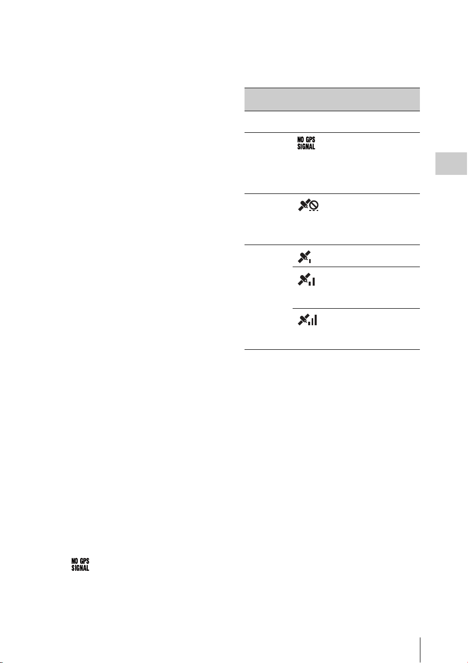
Useful Functions
59
Recording
Compatible format for GPS recording
When the camcorder is in exFAT/HD/XAVC
Mode, you can select any of the following video
formats (page 151).
NTSC Area
XAVC-I 1080/59.94i
XAVC-L50 1080/59.94P
XAVC-L35 1080/59.94P
XAVC-L50 1080/59.94i
XAVC-L35 1080/59.94i
XAVC-L25 1080/59.94i
XAVC-I 1080/29.97P
XAVC-L50 1080/29.97P
XAVC-L35 1080/29.97P
XAVC-I 1080/23.98P
XAVC-L50 1080/23.98P
XAVC-L35 1080/23.98P
XAVC-I 720/59.94P
XAVC-L50 720/59.94P
PAL Area
XAVC-I 1080/50i
XAVC-L50 1080/50P
XAVC-L35 1080/50P
XAVC-L50 1080/50i
XAVC-L35 1080/50i
XAVC-L25 1080/50i
XAVC-I 1080/25P
XAVC-L50 1080/25P
XAVC-L35 1080/25P
XAVC-I 720/50P
XAVC-L50 720/50P
• While [SDI/HDMI/i.LINK I/O Select] is set to
[3G SDI&HD HDMI] and [HD SDI&HD
HDMI], positioning information is output from
the SDI output during positioning, even if a
format other than supported format is set.
1 Check that the camcorder is in standby.
2 To display the GPS reception status on
the LCD monitor/EVF screen, check
that “GPS” in “Display On/Off” of the
LCD/VF SET menu is set to “On.”
3 Set the OTHERS menu>GPS to “On.”
• appears on the LCD monitor/EVF
screen and positioning is prepared. When
positioning is complete, positioning
information is recorded when recording a
video with a compatible format.
GPS reception state
The icon displayed in the viewfinder varies,
depending on the signal reception from the GPS
satellites.
• It may take some time to start acquiring location
information after turning on the camcorder.
• If a positioning icon is not displayed after
several minutes, there may be a problem with
signal reception. Start shooting without location
information, or move to an area with a clear
view of the sky. Shooting when a positioning
icon is not displayed means that location
information will not be recorded.
• The GPS signal may not be received when
indoors or near tall structures. Move to a
location with a clear view of the sky.
• The recording of location information may be
interrupted, depending on the strength of the
received signal, even if a positioning icon is
displayed.
Positioning
status
Display GPS reception
status
Off Not
displayed
GPS is set to off or an
error occurs.
Difficult to
acquire
positioning
Positioning information
cannot be acquired
because the GPS signal
cannot be received.
Move to a place with a
clear view of the sky.
Detecting the
satellite
The camcorder is
detecting the satellite. It
may takes several
minutes to acquire
positioning.
Positioning Weak GPS signal is
being received.
GPS signal is being
received. Positioning
information can be
acquired.
Strong GPS signal is
being received.
Positioning information
can be acquired.

Proxy Recording
60
Recording
You can record proxy file on an SD card
simultaneously while recording on an SxS
memory card.
SDHC memory card* (Speed Class: Higher than
4, Capacity: Up to 32 GB)
SDXC memory card* (Speed Class: Higher than
4)
* Indicated as “SD card” in this Operating Instructions.
When you use an SD card with this camcorder, it
must be formatted using the format function of
this camcorder.
It is also necessary to format an SD card if a
caution message is displayed when you mount it.
1 Set “NW&Proxy/USB” (page 124) in
the NETWORK SET menu to
“Network&Proxy.”
2 Insert the SD card into the slot with the
label facing right.
3 In “Proxy File” (page 125) of the
NETWORK SET menu, specify
“Format SD Card” then select
“Execute.”
The in-progress message and progress status
are displayed. When formatting is complete,
a completion message is displayed. Press the
SEL/SET dial to hide the message.
Notes
• All the data is erased when an SD card is formatted,
and the data cannot be restored.
• The SDHC card is formatted in FAT32, and the SDXC
card is formatted in exFAT.
The remaining time of an SD card can be checked
on the LCD monitor/EVF screen (page 121).
1 Set “NW&Proxy/USB” (page 124) in
the NETWORK SET menu to
“Network&Proxy.”
2 Insert the SD card into the slot with the
label facing right.
To use media formatted with this camcorder in
the slots of other devices
Make a backup of the media, then format it using
the other device.
1 Set “NW&Proxy/USB” (page 124) in
the NETWORK SET menu to
“Network&Proxy.”
2 Insert the SD card into the slot with the
label facing right.
3 Start recording.
When the recording on an SxS memory card
is stopped, proxy recording is also stopped.
Memo
“Rec2-P” appears on the LCD monitor/EVF screen
during proxy recording.
Pressing the assignable button with the proxy feature
assigned enables or disables the proxy recording.
Notes
• The proxy recording does not work when “Format” in
“System” of the OTHERS menu is set to the following
settings.
—exFAT:
XAVC-L50 1080/59.94P, 50P
XAVC-L35 1080/59.94P, 50P
—UDF, exFAT:
HD422 50/720/29.97P, 25P, 23.98P
HQ 1280×720/23.98P
DVCAM 59.94i, 50i, 29.97P, 25P
IMX50 59.94i, 50i, 29.97P, 25P
—FAT:
SP 1440×1080/23.98P
HQ 1280×720/29.97P, 25P, 23.98P
DVCAM 59.94i, 50i, 29.97P, 25P
• When “Size” in “Proxy File” of the NETWORK SET
menu is set to “HD/SD Auto” while “Format” in
“System” of the OTHERS menu is set to “1080/
23.98P” and “23.98P Output” of the VIDEO SET
menu is set to “23.98PsF,” the proxy recording is
disabled.
• The proxy recording does not work during
Simultaneous Recording in the 2 slots, Interval
Recording, Frame Recording, Picture Cache
Recording, Clip Continuous Recording, and Slow &
Quick Motion.
Proxy Recording
Usable SD Cards
Formatting an SD Card
Checking the Remaining Time
Performing Proxy Recording

Proxy Recording
61
Recording
• When performing proxy recording, set Simultaneous
Recording in the 2 slots, Interval Recording, Frame
Recording, Picture Cache Recording, Clip Continuous
Recording, and Slow & Quick Motion to off, and set
“Proxy” of the CAMERA SET menu to “On” (page
112).
• Data integrity is not guaranteed if the power is turned
off or an SD card is removed while it is being accessed.
Data on the SD card may be destroyed. The camcorder
does not have the salvage function that can recover the
damaged material. Be sure that the camcorder is turned
off when you remove the SD card from the camcorder.
Be sure that the ACCESS lamp of the used SD card is
turned off when you turn the camcorder off.
• Make sure that the SD card does not pop out when
inserting or removing it.
• Proxy recording is not available when the following
functions are activated.
—While streaming (when “Setting” in “Streaming”
of the NETWORK SET menu is set to “On”)
When “Auto Upload” in “Proxy File” (page 125)
of the NETWORK SET menu is set to “On,” and
the camcorder is connected to the Internet, the
camcorder automatically uploads a proxy file to
the server set as default on the “Upload Settings”
screen when recording is completed.
For details, see “Auto Upload On/Off” (page 84).
Setting the picture size
Select the picture size with “Size” in “Proxy File”
(page 125) of the NETWORK SET menu.
The file extension is “.mp4.”
The timecode is also recorded simultaneously.
When the GPS function is set to “On,” the GPS
positioning information is recorded.
The recorded file is stored under the “/PRIVATE/
PXROOT/Clip” directory.
The file name is same as the clip name that is
recorded on an SxS memory card.
When “Match Clip Name” is set to “Off,” the file
name generated as the timecode at the start of
recording. (Example: When the recording starts at
14:30:20 05 frame, the file name will be
“14_30_20_05.mp4.”) If there is the file that was
recorded at same time, the camcorder does not
overwrite it and the serial number is added to the
new file name.
Note
When switching memory cards with the SLOT
SELECT button during proxy recording, the clip
name on an SxS memory card is same as the
proxy file name, even if “Match Clip Name” is set
to “On.”
When proxy recording is performed, the still
image of proxy file’s first frame is recorded
simultaneously.
When you use the “Content Browser Mobile”
application, you can display the proxy file’s
thumbnails displayed on the device quickly using
the first frame’s still image.
About the Automatic Upload of the
Proxy File
Changing the Proxy Recording
Setting
About the Recorded File
Storage Destination of the
Recorded File
About the File Name
Recording of the proxy file’s still
images

Connecting to Other Device via Wireless LAN
62
Recording
You can make a wireless LAN connection
between the camcorder and a device such as a
smartphone or tablet by attaching the supplied
IFU-WLM3 USB wireless LAN module.
Notes
• You cannot use a USB wireless LAN module other
than the IFU-WLM3 (supplied) or CBK-WA02
(optional).
• You cannot make a wireless LAN connection when
“Format” in “System” is set to the following settings.
XAVC-L50 1080/59.94P, 50P
XAVC-L35 1080/59.94P, 50P
Making a wireless LAN connection between a
device and the camcorder enables you to do the
following.
• Planning metadata (page 56)
Planning metadata can be sent or received
between the device and this unit.
You can transfer the existing planning metadata
to the unit and apply a clip name or shot marks.
• Remote operation via a wireless LAN (page 78)
You can control the camcorder from a
smartphone, tablet, or computer that is
connected to the camcorder via the wireless
LAN.
• File transferring via a wireless LAN (page 72)
You can transfer a proxy file (low resolution)
that is recorded on an SD card in the camcorder
or original file (high resolution) that is recorded
by the camcorder to the server via the wireless
LAN.
• “Content Browser Mobile” application
In addition to the operations mentioned above,
you can operate the camcorder remotely while
streaming the audio/video of the camcorder,
and perform the settings of the camcorder by
using the “Content Browser Mobile”
application.
When you use the “Content Browser Mobile”
application, confirm you are using the latest
version.
You can operate the following by using this
application.
—Monitoring
You can create a stream (H.264) from the
video/audio of a camcorder, and monitor the
video via the wireless LAN.
—Live Logging Function
You can add shot marks with monitoring
while recording via the device.
The marks are also applied to the proxy file.
You can set the clip position of a file simply
by using this essence mark information.
Notes
• This is only enabled for the same recording
duration proxy file which succeeds the original
file information recorded to this unit.
• When the original file is divided, the essence
marks are not applied to the proxy file.
—Partially transferring the proxy file (page
73) and the original file (page 73)
You can transfer the trimmed partial data by
specifying the In and Out points from the
proxy file and the original file.
For details about the “Content Browser Mobile”
application, contact your Sony dealer or a Sony
service representative.
High quality streaming transmission function
with Sony’s QoS Technology (page 76)
The camcorder can perform high quality
streaming transmission when connected to the
Connection Control Manager (CCM) of the Sony
Network RX Station (optional) or XDCAM air*
in network client mode.
* XDCAM air is a cloud service that is provided by
Sony.
To use this service, registration is required.
XDCAM air is not provided in some regions. For
details on areas where the service is provided, refer to
the following site.
https://www.xdcam-air.com
For more details, contact Sony professional sales
representative.
Compatible devices
You can use a smartphone, tablet, or computer for
setting and operating the camcorder. Compatible
devices, operating systems, and browsers are as
follows.
Connecting to Other
Device via Wireless LAN
Device OS Browser
Smartphone Android4.4/5.x/
6.x/7.x/8.0
Chrome
iOS9.x/10.x/11 Safari
Tablet Android4.4/5.x/
6.x/7.x/8.0
Chrome
iOS9.x/10.x/11 Safari
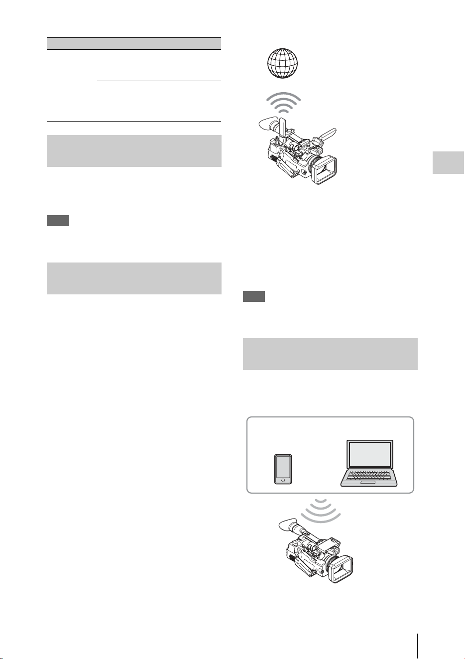
Connecting to Other Device via Wireless LAN
63
Recording
1 Open the cover of the external device
connector, then attach the supplied
wireless LAN module (IFU-WLM3).
Note
Attach/remove the IFU-WLM3 while the camcorder is
turned off.
You can use the CBK-WA02 wireless LAN module
(optional) that is compatible with the 5GHz range.
1 Open the cover of the external device
connector.
2 Attach the network module extension
adaptor (CBK-NA1E) supplied with the
wireless LAN module CBK-WA02
(optional) to the camcorder.
Connect the convex terminal to the external
device connector on the camcorder and
connect the wireless LAN module to the
concave terminal. You can attach the adaptor
to the screw hole (1/4 in.) of the accessory
shoe mount.
3 Attach the wireless LAN module to the
network module extension adaptor.
When the wireless LAN module compatible
with 5GHz is installed and the operation
mode of the wireless LAN is set to “Station”
in the “Network Mode” of the NETWORK
SET menu, you can connect to the access
point compatible with 5GHz.
Note
Attach/remove the CBK-WA02 while the camcorder is
turned off.
The camcorder works as an access point, and
connects to a device via a wireless LAN.
Computer Windows 7/
Windows 8/
Windows 10
Chrome/Safari
Mac OS X
10.10/10.11/
macOS 10.12/
10.13
Safari
Attaching the wireless LAN
module (IFU-WLM3)
Attaching the wireless LAN
module (CBK-WA02)
Device OS Browser
Connecting with the Wireless LAN
Access Point Mode
Internet
Extension adaptor
for network module
+
Wireless LAN
module
Smartphone/
tablet
Computer
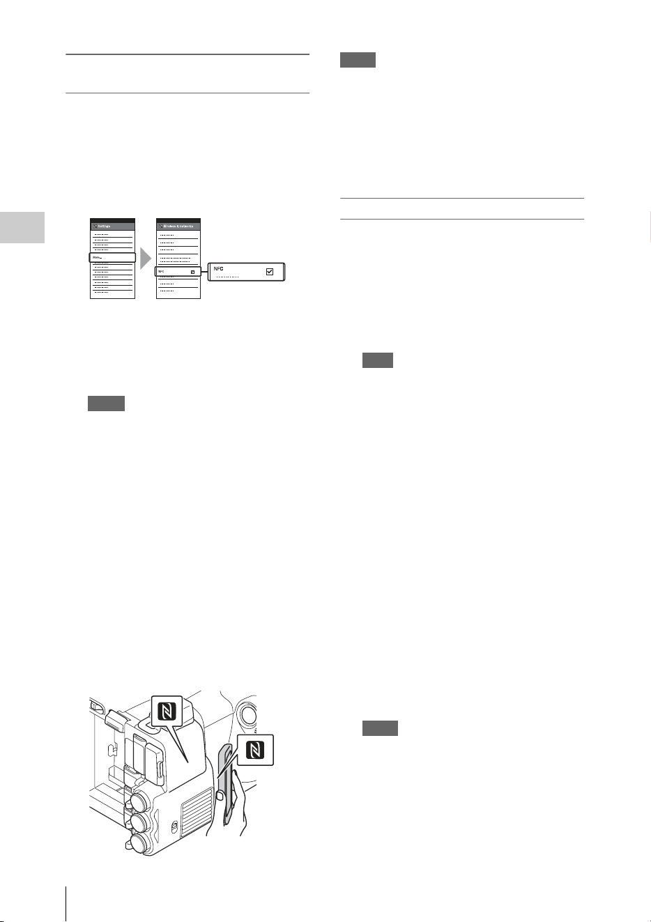
Connecting to Other Device via Wireless LAN
64
Recording
Connecting to an NFC-compatible device
with one-touch operation
You can connect the camcorder to an NFC-
compatible device with one-touch operation by
using the NFC function.
1 Start “Settings” on the device, select
“Other Settings,” then mark the “NFC”
checkbox.
2 Turn the camcorder on.
3 Set “NW&Proxy/USB” (page 124) in
the NETWORK SET menu to
“Network&Proxy.”
It may take time (for about 1 minute) until the
wireless LAN function is activated.
The radio wave intensity indication on the LCD/
EVF screen flashes. Wait until the radio wave
intensity indication stops flashing.
4 Activate the NFC function.
Select “Execute” for “NFC” in the
NETWORK SET menu (page 126).
5 Hold the smartphone near the
camcorder.
The smartphone is connected to the
camcorder and “Content Browser Mobile”
starts.
The “AP” indication appears on the LCD
monitor/EVF screen when smartphone is
connected to the camcorder.
Notes
• Cancel the sleep or screen lock function of the
smartphone in advance.
• Hold the device near to the camcorder without moving
the device until “Content Browser Mobile” starts (1 to
2 seconds).
• If the same SSID is already set in the device, the device
may not connect to the unit depending on the version
of the OS. In this case, delete the registered SSID from
the device.
Connecting to a WPS-compatible device
You can connect the camcorder to a WPS-
compatible device by using the WPS function.
1 Turn the camcorder on.
2 Set “NW&Proxy/USB” (page 124) in
the NETWORK SET menu to
“Network&Proxy.”
Note
It may take time (for about 1 minute) until the
wireless LAN function is activated.
The radio wave intensity indication on the LCD/
EVF screen flashes. Wait until the radio wave
intensity indication stops flashing.
3 Select “Access Point” for “Network
Mode” in the NETWORK SET menu
(page 124).
The “AP” indication appears on the LCD
monitor/EVF screen.
4 Select “Execute” for “WPS” in the
NETWORK SET menu (page 126).
5 Select “Network Setting” > “Wi-Fi
Setting” on the device, then set “Wi-Fi”
to on.
6 Select the camcorder’s SSID from the
SSID list in “Wi-Fi Network” on the
device, then select “WPS Push Button”
in “Option” on the device.
Notes
• The operation method differs depending on the
device.
• For the SSID and password of the camcorder,
check “SSID & Key(AP)” in the NETWORK
SET menu (page 126).
7 Start the browser on the device, then
access “http://192.168.1.1:8080/
index.html.”
Note
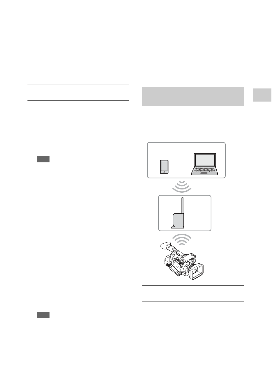
Connecting to Other Device via Wireless LAN
65
Recording
The screen for inputting “User Name” and
“Password” appears.
For the user name and password of the access
authentication, check “User Name” and
“Password” in the NETWORK SET menu
(page 128).
8 Input the user name and password, then
select “OK.”
Connecting by inputting an SSID and
password on a device
You can connect the camcorder to a device by
inputting an SSID and password on a device.
1 Turn the camcorder on.
2 Set “NW&Proxy/USB” (page 124) in
the NETWORK SET menu to
“Network&Proxy.”
Note
It may take time (for about 1 minute) until the
wireless LAN function is activated.
The radio wave intensity indication on the LCD/
EVF screen flashes. Wait until the radio wave
intensity indication stops flashing.
3 Select “Access Point” for “Network
Mode” in the NETWORK SET menu
(page 124).
The “AP” indication appears on the LCD
monitor/EVF screen.
4 Select “Network Setting” > “Wi-Fi
Setting” on the device, then set “Wi-Fi”
to on.
5 Connect the device to the camcorder by
selecting the camcorder’s SSID from
the SSID list in “Wi-Fi Network” and
inputting the password on the device.
For the SSID and password of the camcorder,
check “SSID & Key(AP)” in the NETWORK
SET menu (page 126).
Note
The operation method differs depending on the
device.
6 Start the browser on the device, then
access “http://192.168.1.1:8080/
index.html.”
The screen for inputting “User Name” and
“Password” appears.
For the user name and password of the access
authentication, check “User Name” and
“Password” in the NETWORK SET menu
(page 124).
7 Input the user name and password, then
select “OK.”
The camcorder connects to an existing access
point of the wireless LAN as a client. The
camcorder and device connect via the access
point.
Connecting to the access point with the
WPS function
If the access point is compatible with the WPS
function, you can connect to the access point with
simple settings. If the access point is not
compatible with the WPS function, see “To
connect to the access point in the station mode
without the WPS function” (page 83).
1 Turn the access point on.
Connecting with the Wireless LAN
Station Mode
Smartphone/
tablet
Computer
Access
point

Connecting to Other Device via Wireless LAN
66
Recording
2 Turn the camcorder on.
3 Set “NW&Proxy/USB” (page 124) in
the NETWORK SET menu to
“Network&Proxy.”
Note
It may take time (for about 1 minute) until the
wireless LAN function is activated.
The radio wave intensity indication on the LCD/
EVF screen flashes. Wait until the radio wave
intensity indication stops flashing.
4 Set “Network Mode” in the
NETWORK SET menu (page 124) to
“Station.”
Note
It may take time (for about 1 minute) until the
camcorder is in the station mode.
5 Execute “WPS” in the NETWORK
SET menu.
6 Press the WPS button of the access
point.
For the operation of the WPS button, refer to
the operating instructions of the access point.
When the connection is completed, the radio
wave intensity indication on the LCD/EVF
screen lights at a strength of more than 1.
Note
If the connection fails, perform steps from step 1
again.
7 Connect the device to the access point.
For connecting, refer to the operating
instructions of the device.
8 Start the browser on the device, then
access to “http://<IP address that the
access point assigns to the
camcorder>:8080/index.html.”
For the camcorder’s IP address, check “IP
Address” in the NETWORK SET menu
(page 126).
The screen for inputting “User Name” and
“Password” appears.
For the user name and password of the access
authentication, check “User Name” and
“Password” in the NETWORK SET menu
(page 124).
9 Input the user name and password, then
select “OK.”
The Web menu of the camcorder appears on
the browser. For details, see “About the Web
Menu” (page 79).
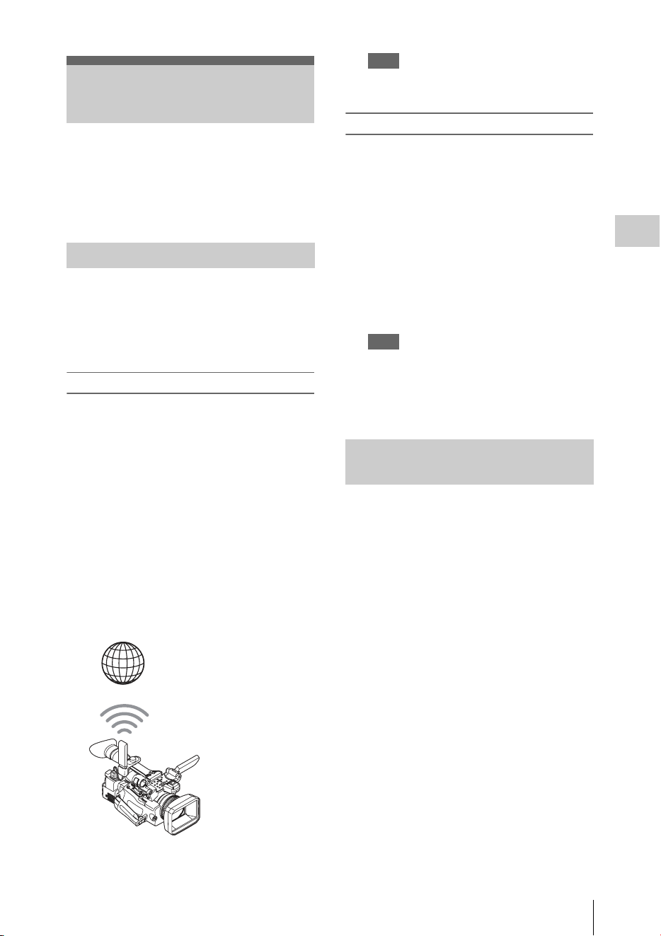
Connecting to the Internet
67
Recording
You can connect the camcorder to the Internet by
attaching an optional modem, a wireless USB
module IFU-WLM3 (supplied), or a USB-RJ45
adaptor supplied with an optional network
adaptor kit CBK-NA1 to the camcorder.
You can connect the camcorder to the Internet via
a 3G/4G network by attaching an optional modem
to the unit.
For compatible modems, contact your Sony
dealer or a Sony service representative.
Attaching the modem to the camcorder
1 Open the cover of the external device
connector.
2 Attach the extension adaptor for
network module supplied with the
optional network adaptor kit CBK-NA1
to the camcorder.
Connect the convex terminal to the terminal
for the USB wireless LAN module on the
camcorder and connect the concave terminal
to the modem. You can attach the adaptor to
the screw hole (1/4 in.) of the accessory shoe
mount.
3 Attach the modem to the extension
adaptor for network module.
Note
Attach/remove the modem while the camcorder is
turned off.
Connecting
1
Turn the camcorder on.
2 Set “NW&Proxy/USB” (page 124) in
the NETWORK SET menu to
“Network&Proxy.”
• When an optional modem compatible to the
camcorder is attached, “Network Mode” in
the NETWORK SET menu is
automatically set to “Modem,” then the
camcorder is ready to be connected to the
Internet.
Note
It may take a time (for 30 to 60 seconds) until the
camcorder is in the modem mode. Wait until the
“3G/4G” indication for the network connection
status on the LCD Monitor/EVF screen (page 16) is
turned on.
You can connect the camcorder to the Internet in
the Wi-Fi station mode by attaching the USB
wireless LAN module IFU-WLM3 (supplied),
via an optional 3G/4G/LTE access point or by
tethering to a device.
Connecting to the
Internet
Connecting with a modem
Internet
Extension adaptor
for network module
+ Modem
Connecting with the wireless LAN
Wi-Fi station mode
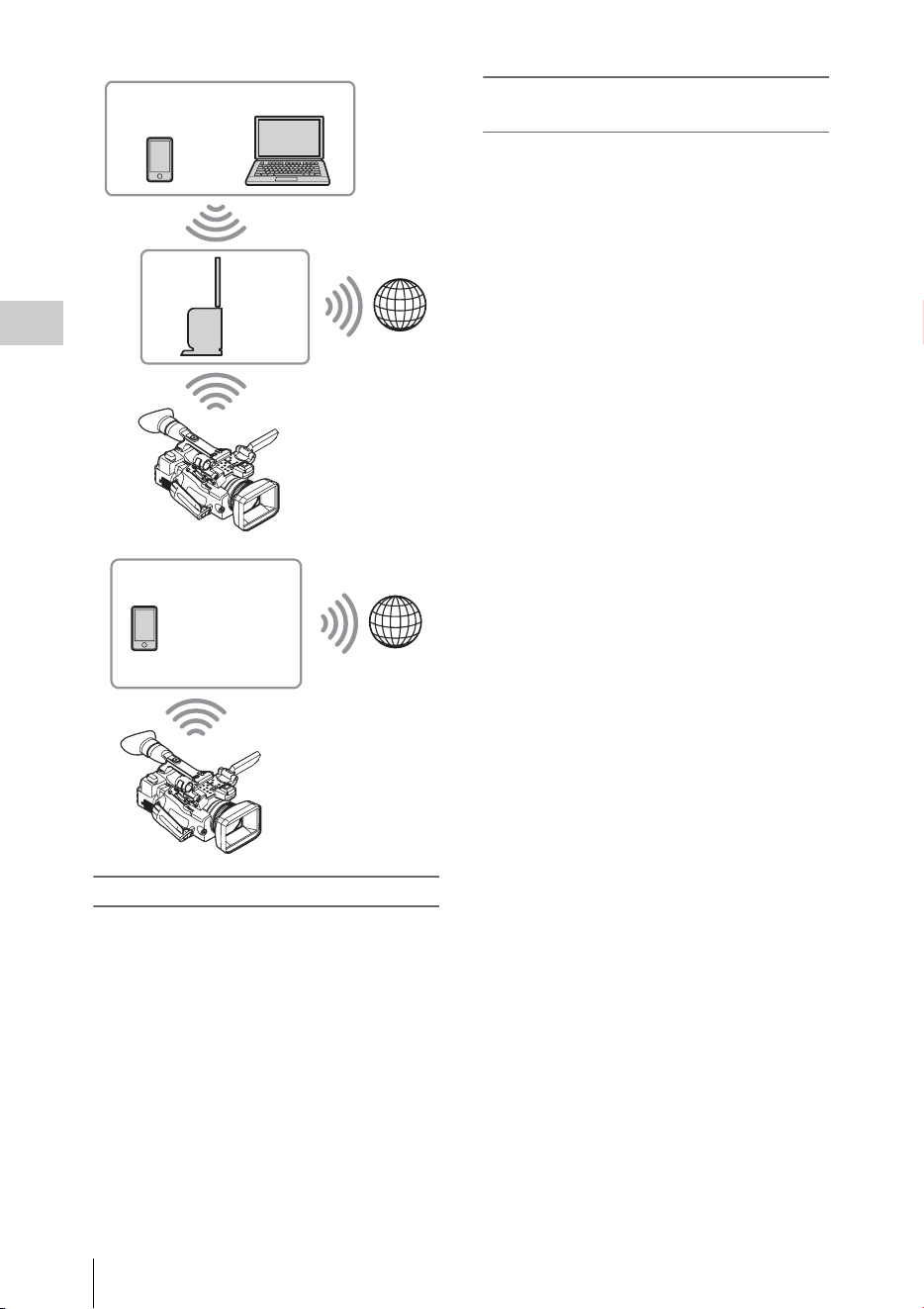
Connecting to the Internet
68
Recording
Connecting to the Internet using a device
If the access point or device is compatible with
the WPS function, connect the camcorder to the
Internet by performing procedures of
“Connecting to the access point with the WPS
function” (page 65). If the access point or device
is not compatible with the WPS function, connect
the camcorder to the Internet by performing
procedures of “To connect to the access point in
the station mode without the WPS function”
(page 83).
Before connecting, turn the access point or device
on, and activate its tethering function.
Connecting to the access point using the
Setup menu
By using the Setup menu, you can connect the
camcorder to the access point that you want to
connect, and configure connection settings.
To detect the desired access point, you can use the
automatic network detection feature.
Using the automatic network detection feature
1 Refer to “Connecting to the access point
with the WPS function” (page 65), and
follow the steps from 1 to 4.
2 Select “Execute” for “Scan Networks”
(page 127) of “Station Set” in the
NETWORK SET menu.
The camcorder starts to detect the connection
destinations.
When the destinations are detected, the result
list of “Scan Networks” is displayed.
3 Use the up/down button or the jog dial
to select the destination, and then press
the SEL/SET button or the jog dial.
The display returns to the “Station Set”
screen, and the selected destination is
displayed in “SSID.”
4 Select “Password,” and set the
password on the password entering
screen.
When the camcorder has been connected to
the access point before the connection
destinations are detected automatically, and
the same SSID is selected, the password is
displayed.
After the password has been set, the display
returns to the “Station Set” screen.
5 Perform the following connection
settings in “Station Set.”
•“DHCP”
Set the DHCP setting.
When it is set to “On,” the IP address is
assigned to the camcorder automatically.
To assign the IP address to the camcorder
manually, set it to “Off.”
• “IP Address”
Input the IP address of the camcorder.
Smartphone/
tablet
Computer
Access
point
Internet
Smartphone/
tablet
Internet

Connecting to the Internet
69
Recording
This setting is available only when
“DHCP” is set to “Off.”
•“Subnet mask”
Input the subnet mask of the camcorder.
This setting is available only when
“DHCP” is set to “Off.”
• “Gateway”
Input the default gateway for the access
point.
This setting is available only when
“DHCP” is set to “Off.”
• “DNS Auto”
Set to acquire DNS automatically.
When it is set to “On,” the DNS server
address is automatically acquired.
• “1st DNS Server”
Input the primary DNS server for the
access point.
This setting is available when “DNS Auto”
is set to “Off.”
• “2nd DNS Server”
Input the secondary DNS server for the
access point.
This setting is available only when “DNS
Auto” is set to “Off.”
6 When you complete the inputs, select
“Execute” in “Set” to confirm settings.
Note
If you changed the settings, make sure to select
“Execute” in “Set.”
If you do not select “Execute,” changed settings are
not applied.
Note
It may take some time (for 30 to 60 seconds) before
the camcorder enters in the “Station” mode. Wait
until the “radio wave” icon that indicates the
network connection status on the LCD Monitor/
EVF screen (page 16) lights up.
Entering the SSID of the access point manually
1 Refer to “Connecting to the access point
with the WPS function” (page 65), and
follow the steps from 1 to 4.
2 Configure connection settings in
“Station Set” (page 127) of the
NETWORK SET menu.
• “SSID”
Enter the SSID of the destination access
point.
• “Password”
Enter the password of the destination
access point.
•“DHCP”
Set the DHCP setting.
When it is set to “On,” the IP address is
assigned to the camcorder automatically.
To assign the IP address to the camcorder
manually, set it to “Off.”
• “IP Address”
Input the IP address of the camcorder.
This setting is available only when
“DHCP” is set to “Off.”
• “Subnet mask”
Input the subnet mask of the camcorder.
This setting is available only when
“DHCP” is set to “Off.”
•“Gateway”
Input the default gateway for the access
point.
This setting is available only when
“DHCP” is set to “Off.”
• “DNS Auto”
Set to acquire DNS automatically.
When it is set to “On,” the DNS server
address is automatically acquired.
• “1st DNS Server”
Input the primary DNS server for the
access point.
This setting is available when “DNS Auto”
is set to “Off.”
• “2nd DNS Server”
Input the secondary DNS server for the
access point.
This setting is available only when “DNS
Auto” is set to “Off.”
3 When you complete the inputs, select
“Execute” in “Set” to confirm settings.
Note
If you changed the settings, make sure to select
“Execute” in “Set.”
If you do not select “Execute,” changed settings are
not applied.
Note
It may take some time (for 30 to 60 seconds) before
the camcorder enters in the “Station” mode. Wait
until the “radio wave” icon that indicates the
network connection status on the LCD Monitor/
EVF screen (page 16) lights up.
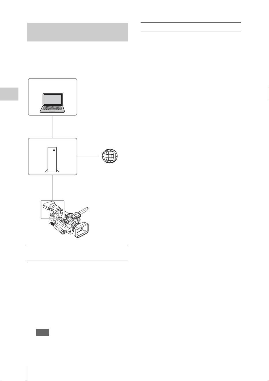
Connecting to the Internet
70
Recording
You can connect the camcorder to the Internet by
attaching the USB-RJ45 adaptor supplied with
the optional network adaptor kit CBK-NA1, via
LAN cables connected to an internet router.
Attaching the USB-RJ45 adaptor to the
camcorder
1
Open the cover of the external device
connector.
2 Attach the USB-RJ45 adaptor to the
camcorder.
Use the belt supplied with the network
adaptor kit CBK-NA1 to attach the network
cable connected to a USB-RJ45 adaptor to
the camcorder.
Note
Attach/remove the USB-RJ45 adaptor while the
camcorder is turned off.
Connecting
1
Turn the camcorder on.
2 Set “NW&Proxy/USB” (page 124) in
the NETWORK SET menu to
“Network&Proxy.”
• If USB-RJ45 adaptor is attached properly,
“Network Mode” is automatically set to
“Wired LAN.”
3 Perform connection settings in the
Wired LAN Set menu.
•“DHCP”
Set the DHCP setting.
When you set to “On,” the IP address is
assigned to the camcorder automatically.
To assign the IP address to the camcorder
manually, set to “Off.”
• “IP Address”
Input the IP address of the camcorder.
This setting is available only when
“DHCP” is set to “Off.”
• “Subnet mask”
Input the subnet mask of the camcorder.
This setting is available only when
“DHCP” is set to “Off.”
•“Gateway”
Input the default gateway for the access
point.
This setting is available only when
“DHCP” is set to “Off.”
• “DNS Auto”
Set to acquire DNS automatically.
When set to “On”, the DNS server address
is automatically acquired.
• “1st DNS Server”
Input the primary DNS server for the
access point.
This setting is available when “DNS Auto”
is set to “Off.”
• “2nd DNS Server”
Input the secondary DNS server for the
access point.
This setting is available only when “DNS
Auto” is set to “Off.”
4 When you complete the inputs, select
“Execute” in “Set” to confirm settings.
Connecting to the Internet with a
LAN cable
Computer
Router
USB-RJ45 adaptor
Internet

Connecting to the Internet
71
Recording
Note
If you changed the settings, make sure to select
“Execute” in “Set.”
If you do not select “Execute”, changed settings are
not applied.
Note
It may take a time (for 30 to 60 seconds) until the
camcorder is in the wired LAN mode. Wait until the
“LAN icon” indication for the network connection
status on the LCD Monitor/EVF screen (page 16) is
turned on.
A list of functions for each Network Mode in NETWORK SET menu is as follows.
1) The function of a device connected with the camcorder via a network
Notes
• When you use monitoring of the “Content Browser Mobile” application, the monitoring video image
may stop due to signal conditions when used on mobile devices.
• To prevent unauthorized access from the internet, we recommend to operate the unit remotely (set
“Network Remote” to “On”) when the wired LAN network is not connected to the internet. When
connecting to the internet, confirm whether the connecting destination is a secure network.
For a network connection, the USB wireless LAN module, 3G/4G/LTE USB modem, or USB-RJ45
adaptor is required.
Notes
• The wireless LAN module may not be available in some countries/regions.
• The frequency band for the wireless LAN module is shared by various devices. Depending on the use
environment, transmission speed and distance may be decreased, or communication may be
disconnected, by using other devices.
• To use the 3G/4G/LTE services, you need to contract with a cell phone company.
• For details about the required compatible device for the network connection, contact your Sony dealer
or a Sony service representative.
List of functions for network connections
Functions Network Mode
Access Point Station Modem Wired LAN Off
Proxy Recording (page 60) aaaaa
Proxy playback (page 79)
a
1)
a
1)
×× ×
Transferring a file (page 72) × aa a ×
Transmitting streaming (page 74) × aa a ×
Monitoring (page 80)
a
1)
a
1)
×
a
1)
×
Remote Commander (page 78)
a
1)
a
1)
×
a
1)
×
Required devices for network connections
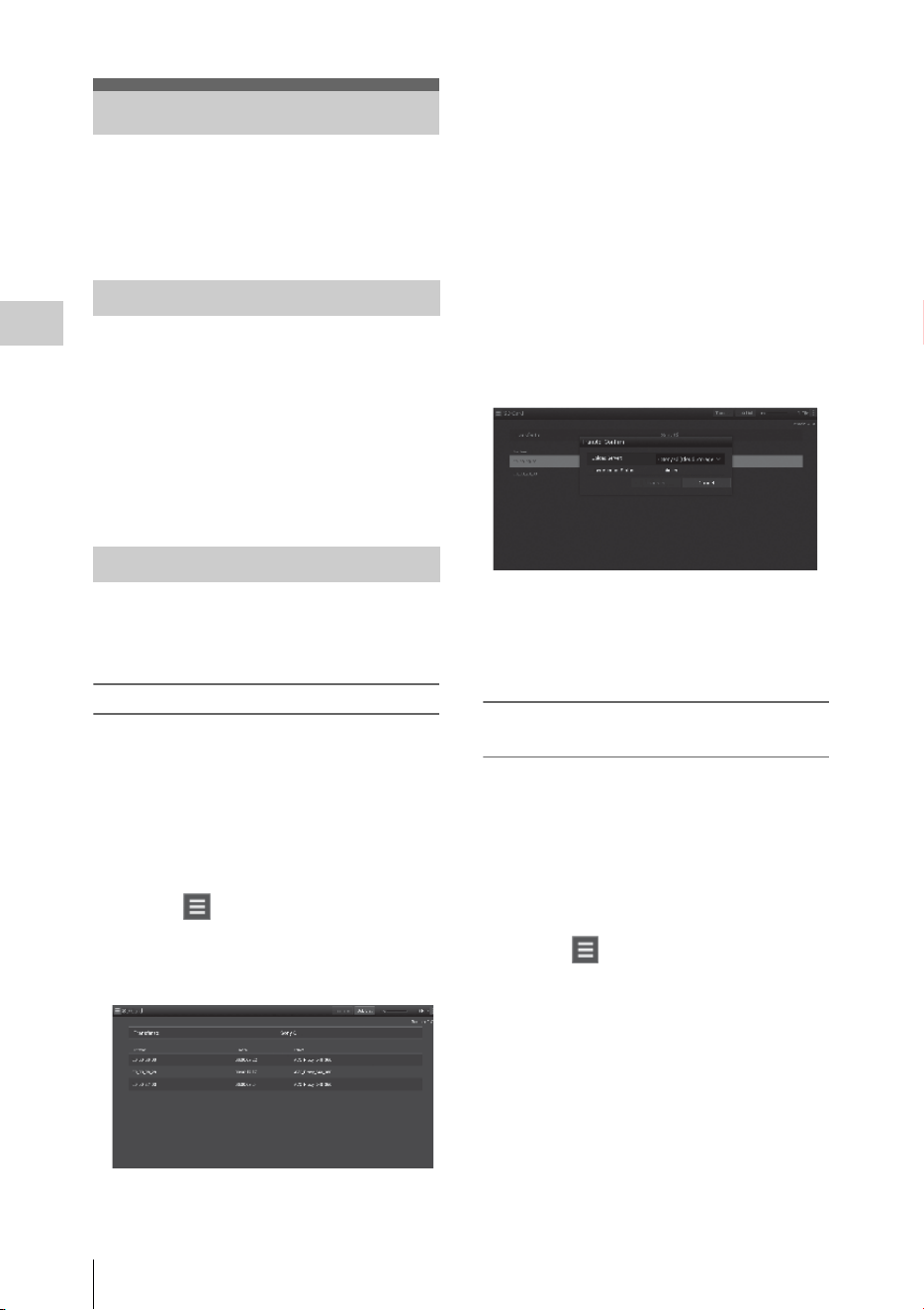
Uploading a File
72
Recording
You can upload a proxy file or original file that is
recorded on the camcorder to the server on the
Internet via a 3G/4G/LTE network or an access
point.
To connect to the Internet
Connect the camcorder to the Internet by
following the procedure in “Connecting to the
Internet” (page 67).
To register the server for uploading
Register the server for uploading in advance.
For details about registering the server, see
“Register the server for uploading” (page 85).
Upload the file that is recorded on an SD card, or
the original file that is recorded on an SxS
memory card, to the server.
Uploading a proxy file on an SD card
1
Connect a device to the camcorder via a
wireless LAN, start the browser on the
device, then access the camcorder from
the browser (page 62).
2 Display the file list screen to select the
file.
Touch “ ” > “Media Info” > “SD Card.”
The “SD Card,” “Slot A,” or “Slot B” screen
appears.
Example: “SD Card” screen
3 Select the file.
Select the file by touching the file. To cancel,
touch the file again.
You can check the file by double touching
the file to play back (SD card only).
4 Touch “Transfer.”
The server that you set to the default server at
“Default Server” in “Register the server for
uploading” (page 85) appears.
To change the server, touch the server to
display the server list, then select a server.
Input the directory for the server to
“Directory” if necessary.
5 Touch “Transfer.”
The camcorder starts uploading the selected
file.
To cancel uploading, touch “Cancel.”
Uploading an original file on an SxS
memory card
1
Connect a device to the camcorder via a
wireless LAN, start the browser on the
terminal device, then access the
camcorder from the browser (page 62).
2 Display the file list screen to select the
file.
Touch “ ” > “Media Info” > “Slot A” (for
a memory card in the slot A) or “Slot B” (for
a memory card in the slot B).
The “SD Card,” “Slot A,” or “Slot B” screen
appears.
Example: “SD Card” screen
Uploading a File
Preparations
Selecting the File and Uploading
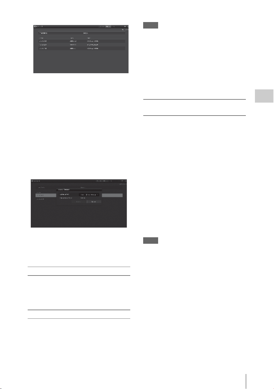
Uploading a File
73
Recording
3 Select the file.
Select the file by touching the file. To cancel,
touch the file again.
You can check the file by double touching
the file to play back (SD card only).
4 Touch “Transfer.”
The server that you set to the default server at
“Default Server” in “Register the server for
uploading” (page 85) appears.
To change the server, touch a server to
display the server list, then select the server.
Input the directory for the server to
“Directory” if necessary.
5 Touch “Transfer.”
The camcorder starts uploading the selected
file.
To cancel uploading, touch “Cancel.”
Checking the file uploading
You can check the upload status on the “Job List”
screen that is displayed by touching “Job List” on
the “SD Card,” “Slot A,” or “Slot B” screen (page
86).
Partial transfer of a proxy file
When you use the “Content Browser Mobile”
application, you can transfer a cutout part of a file
by specifying In and Out points in the proxy file.
You can also transfer the cutout parts of multiple
files using the Storyboard.
Notes
• The maximum 15-frame margin is attached in front
and behind the clipped point in a generated file.
• When you clip the proxy file recorded with network
function software V1.32 or earlier, the data may not be
taken to the non-linear editor.
• When you transfer the data partially based on the
Storyboard, the file to transmit the information of the
Storyboard to the non-linear editor is displayed in the
“Job List.” To transfer this file, “General/Sony/tmp” is
created in the SD card. This file is saved temporally in
it while transferring and it is deleted when transfer is
completed.
Partial transfer of an original file
recorded on this unit
When you use the “Content Browser Mobile”
application, you can transfer a cutout part of a file
by specifying In and Out points in the original file
recorded by this unit.
You can also transfer the cutout parts of multiple
files using the Storyboard.
Compatible formats for the original file are as
follows:
exFAT Mode
XAVC-I
XAVC-L50,35,25
MPEG2 HD422
MPEG2 HD420HQ
UDF Mode
MPEG2 HD422
MPEG2 HD420HQ
Notes
• To transfer the original file partially using the “Content
Browser Mobile,” record the proxy file with the same
file name as the original file with the following
settings.
—Set “Proxy” of the CAMERA SET menu to “On.”
—Set “Match Clip Name” of the VIDEO SET menu
to “On.”
—Set “NCM with Proxy” in “NW Client Edit” of the
NETWORK SET menu to “Enable” when the
network client mode is activated.
• While transferring the original file partially, the
following operations cannot be done.
—Clip operation
—Formatting media
—Connecting to the PC via USB
• While transferring the original file partially, the time
for storing the images to the picture cache memory of
the Picture Cache Recording will be less than the time
set by “Rec Time” in “P.Cache Rec” of the CAMERA
SET menu.

Transmitting streaming video and audio
74
Recording
You can transmit the video and audio captured/
played back with the camcorder via Internet or
local network.
To connect to the Internet
Connect the camcorder to the Internet by
following the procedure of “Connecting to the
Internet” (page 67).
To connect to the local network
Connect the camcorder to the local network by
following the procedure of “Connecting to Other
Device via Wireless LAN” (page 62).
To set the transmission destination of the
streaming
Up to 3 settings for the streaming can be
maintained as presets.
1 Specify “Preset Edit” in “Streaming
Edit” of the NETWORK SET menu
(page 125) and select “Preset1” (or
“Preset2,” “Preset3”) for the
transmission destination.
2 Set “Type,” “Size,” “Bit Rate,”
“Dest.Address,” and “Dest.Port” for
the stream.
For details such as limitations, see
“Streaming settings” (page 81) in “About the
Web Menu.”
3 When you complete the settings in step
2, Select “Execute” in “Set” to confirm
settings.
Note
When you change the settings of “Type,” “Size,”
“Bit Rate,” “Dest.Address,” and “Dest.Port”, select
“Execute” in “Set.” If you do not select “Execute”,
changed settings are not applied.
The streaming methods for the camcorder are
MPEG2-TS/UDP and MPEG2-TS/RTP.
Set in “Type.”
To view streaming video and audio, use a receiver
that supports these methods.
For details about the receiver, see the operating
instructions of the receiver.
Transmitting streaming
video and audio
Preparations
Transmitting streaming video and audio
75
Recording
1 Set “Setting” to “On” in “Streaming” of the NETWORK SET menu (page 124).
The streaming status is displayed on the LCD monitor/EVF screen, and streaming starts.
You can assign the “Streaming” to an assignable button. For details about assigning, refer to
“Assignable Buttons” (page 40) in the Operating Guide.
The streaming status is displayed in the streaming status indication area (page 14) on the LCD monitor/
EVF screen.
Notes
• You cannot start streaming when “NW&Proxy/USB” in the NETWORK SET menu is set to “USB A” or “Off.”
• You cannot start streaming when “Setting” in “NW Client Mode” of the NETWORK SET menu is set to “On.”
• The setting automatically turns to “Off” when the camcorder is turned off. To transmit streaming again, set
“Setting” to “On” in “Streaming.”
• It may take several tens of seconds to stream actual video or audio after starting streaming.
• If you set the transmission destination of the streaming incorrectly or the camcorder does not connect to the
network, “×” appears on the screen as the streaming status indication.
• Video/audio data is transmitted via the Internet as is. Therefore, there is a possibility of data leakage. Make sure
that the destination is able to receive the streaming data. Data may be transmitted to an unexpected receiver due
to the incorrect setting of an address, etc.
• Depending on the network conditions, not all frames may be played back.
• The picture quality deteriorates at scenes where there is quick motion.
• When streaming is set to a large size and small bit rate, not all frames may be played back.
To improve this situation, select a smaller size in “Size.”
• When you start streaming, proxy recording and file transferring are not available.
When you start streaming during proxy recording or a file transfer, proxy recording or file transferring
automatically stops.
• When you start streaming during proxy recording or file transfer by pressing the assignable button to which
“Streaming” is assigned, proxy recording or file transferring automatically stops. If streaming stops after the proxy
recording is stopped, proxy recording starts. In this case, the clip of the proxy recording is different from that of
the stopped one. In the case of a file transfer, file transferring resumes.
Starting streaming
Conditions
NETWORK SET
menu>Network Mode
NETWORK SET
menu>Streaming>Setting
Streaming status Icon
Off – – No display
Except for “Off” Off – No display
On No streaming
Streaming video
Error

Transmitting streaming video and audio
76
Recording
1 Set “Setting” to “Off” in “Streaming”
of the NETWORK SET menu (page
124).
Streaming also stops by pressing the
assignable button to which “Streaming” is
assigned.
When the camcorder is connected to a device via
Wireless LAN (page 62) or is connecting to the
Internet with the wireless LAN station mode
(page 67), you can also set the transmission
destination and starting/stopping streaming from
the Web menu (page 79).
By using the Sony network RX station (optional)
or XDCAM air in combination with this network
client mode, high quality streaming with less
packet loss using the Sony QoS technology is
available.
While using the camcorder with “NW Client
Mode,” operate the camcorder from the
Connection Control Manager (CCM) application
of Network RX Station or XDCAM air.
High Quality Streaming Transmission
with Sony’s QoS Technology
1
Connect the camcorder with the
network.
2 To specify the connection destination,
select “Preset1” (“Preset2” or
“Preset3”) for “Preset Edit” in “NW
Client Edit” (page 124) of the
NETWORK SET menu.
To specify the connection destination in
“NW Client Mode,” “Preset1,” “Preset2,”
and “Preset3” are available.
3 Set “CCM Address,” “CCM Port,”
“User Name,” “Password,” and “NCM
with Proxy” accordingly.
Notes
• When you set “NCM with Proxy” in “NW Client Edit”
to “Enable,” the proxy recording is available even if
the network client mode is activated. To activate the
“NCM with Proxy” settings, set “Proxy” in the
CAMERA SET menu to “On.”
• While selecting “Disable” of “NCM with Proxy” in
“NW Client Edit” and you are recording, the proxy
recording stops if you set the network client mode to
“On.” In case the recording to the SxS memory card
continues, the proxy recording restarts by setting the
network client mode to “Off.”
• While selecting “HD/SD Auto” of “Size” in “Proxy
File,” “NCM with Proxy” cannot be set. When setting
to “Enable,” the value is held and storing operation is
not performed.
• When you input “User Name” and “Password,” yen
sign (¥) is displayed instead of a backslash (\) on this
camcorder.
4 When you complete the settings, select
“Execute” in “Set” to confirm settings.
The set items are confirmed.
5 Select “Preset1,” “Preset2,” or
“Preset3” for “Preset Select” in “NW
Client Mode” (page 124) of the
NETWORK SET menu.
6 Set “Setting” in “NW Client Mode” of
the NETWORK SET menu to “On.”
The network client mode is enabled and the
camcorder is connected with the network RX
station or XDCAM air. The transmission of live
video is started by operating the network RX
station or XDCAM air. For details, refer to the
operating instructions of the network RX station
or the online help of XDCAM air. You can assign
“Setting” (On/Off) in “NW Client Mode” to an
assignable button.
Notes
• Switching to the network client mode cannot be not
performed during normal streaming (page 74).
• When switched to the network client mode, streaming
or monitoring cannot be performed.
• When switched to the network client mode while
monitoring, the operation stops.
• File transferring cannot be not performed while
streaming by network client mode.
• File transferring stops if you start streaming in network
client mode while transferring. File transferring
restarts if you stop streaming.
• The streaming bit rate that can be set on the Network
RX Station or XDCAM air is limited depending on the
proxy recording format.
Stop streaming
About the Network Client Mode

Transmitting streaming video and audio
77
Recording
—When the proxy recording format is 1280 × 720
9Mbps/6Mbps: The streaming bit rate is 1Mbps or
less of Very Low.
—When the proxy recording format is 640 × 360
3Mbps or less: The streaming bit rate is 3Mbps or
less of Low.
• The proxy format cannot be changed while in the
network client mode. To change the proxy format, turn
the network client mode off.
File Transferring in Network Client Mode
You can transfer the file to the server set on CCM
by connecting the unit to the CCM of Network
RX Station (optional) or XDCAM air in network
client mode.
To operate on the CCM
You can perform the file transferring operation on
the CCM that is connected in network client
mode.
1 Connect to the CCM in network client
mode.
2 Perform the file transferring operation
on the CCM.
For details about the file transferring
operation on the CCM, refer to the operating
instructions of the CCM.
To operate on the device that is connected to the
camcorder
You can perform the file transferring operation on
the device (such as smartphone, tablet, PC, etc.)
that is connected to the camcorder in the same
network.
1 Connect to the CCM in network client
mode.
2 Start the browser of the device that is
connected to the camcorder in the same
network, then access the camcorder.
3 Select the file to transfer on the file list
screen.
Refer to steps 2 and 3 of “Uploading a proxy
file on an SD card” (page 72) or “Uploading
an original file on an SxS memory card”
(page 72).
4 Tap “Transfer.”
“NCM: RX Server” is displayed on the
destination.
Specify “NCM: RX Server” for the
destination.
5 Tap “Transfer.”
File transferring to the server set by the CCM
starts.
Note
You can set “NCM: RX Server” as the destination even
if the camcorder is not connected in network client mode.
In this case, file transferring is suspended. File
transferring to the server set on the CCM starts after the
camcorder is connected to the CCM in network client
mode.
When “NW Client Mode” is set to “On,” the connection status with CCM (Connection Control Manager
for the network RX station (optional) or XDCAM air) is displayed.
Conditions
Indication
NETWORK SET
menu>Network
Mode
NETWORK SET
menu>NW Client
Mode>Setting
Status
Off Off – No display
Off On Not connected to CCM No display
Other than “Off” Connected to CCM Lit
Connecting to CCM Flashing
CCM connection error Lit
Using the Wi-Fi Remote Commander
78
Recording
When a wireless LAN connection is established
between a device such as smartphone, tablet, PC,
etc., and the camcorder, the Wi-Fi remote
commander appears on the device screen and the
device can be used as a remote commander.
You can start/stop recording, adjust iris/focus/
zoom, etc., with a Wi-Fi connected device. This
function is useful for setting the camcorder in a
remote place, such as the top of a crane, etc.
Notes
• When iris is not set to auto, “IRIS” slider operation and
ON/OFF setting of “Auto IRIS” are not available.
• When the focus ring is pulled rearward, “FOCUS”
slider operation and ON/OFF setting of “Auto Focus”
are not available.
• When the ZOOM switch is set to MANUAL, “ZOOM”
slider operation is not available.
The displays of Wi-Fi remote commander
For smartphone
For Tablet
To display the Wi-Fi remote commander
To display the Wi-Fi remote commander on a
device screen, settings are required on both the
device and camcorder.
Camcorder settings
1 Set “Network Remote” in the
NETWORK SET menu (page 124) to
“On.”
Device settings
Set the smartphone, tablet, PC, etc., to be used as
the Wi-Fi remote commander.
1 Make a wireless LAN connection
between the device and camcorder
(page 62).
2 Launch the browser and input http://
<camcorder’s IP address> (refer to “IP
Address” in the NETWORK SET menu
(page 126))/rm.html.
Example: When the IP address is
192.168.1.10, input “http://192.168.1.10/
rm.html” in the address bar.
The Wi-Fi remote commander will appear on
the device screen when the Wi-Fi connection
is established.
Thereafter operate the camcorder as shown
on the screen of the Wi-Fi connected device.
The REC button becomes unavailable when
the Lock switch is dragged to the right.
Notes
• Depending on the device, the Wi-Fi remote
commander may not appear properly on the device’s
screen even though you input “http://<camcorder’s IP
address> (page 126)/rm.html” in the address bar. In
this case, input “rms.html” for a smartphone or
“rmt.html” for a tablet at the end of the address to
display the Wi-Fi remote commander properly.
Using the Wi-Fi Remote
Commander

About the Web Menu
79
Recording
• The Wi-Fi remote commander on the device’s screen
may no longer match the actual status of the camcorder
in the following cases. When this happens, refresh the
browser on the device.
—when the camcorder is restarted while the Wi-Fi
connection is established
—when the camcorder is controlled directly while
the Wi-Fi connection is established
—when the device is reconnected
—when you operate forward/backward on the
device’s browser.
• If the Wi-Fi signal is poor, the Wi-Fi remote
commander may not work properly.
The Web menu of the camcorder appears by
accessing the camcorder from the browser of a
device that is connected to the camcorder via a
wireless LAN. You can perform the settings for the
wireless function or the operation of the file transfer.
Initial screen
When starting the browser on the device and
accessing “http://<camcorder’s IP address>
(NETWORK SET>IP Address) /rm.html,” the
“SD Card” screen in “Media Info” of the
camcorder appears on the browser.
About the setting menu
The setting menu appears by touching at the
upper left of the screen. Touch the item that you
want to set.
“Device Status”
• “Short Cut”
“Media”: Short-cut button for the “SD Card”
screen (page 72)
Settings: Shortcut to the setting screen (page
80) for the camcorder
• “Status”
•Network Client
Displayed when the network client mode is on.
Connected to CCM Name: Connection
completed
Error display: “Destination Address Error,”
“Authentication Failed,” “No Internet Access,”
“Certificate is not yet valid,” “Certification
Error”
Note
When “Certificate is not yet valid” appears, the date may
be set to an invalid value. Check the date setting.
•Streaming
Monitoring: Streaming is on the “Off” status
Running: MPEG2-TS/UDP or MPEG2-TS/
RTP
Displayed as follows when the network client
mode is on.
Running: While streaming
Stop: Streaming is stopped
Initializing: Streaming is preparing
Error Indications: Destination Address Error,
No Internet Access
About the Web Menu
About the Web Menu
80
Recording
• Proxy
Recording: Recording a proxy file
Stop: Recording is stopped
Disabling: Cannot record
“Remain”: SD card remaining space indication
“Warning/Error”: Warning/Error indication
(“Wxx-xxx” is a warning number. “Exx-xxx” is
an error number (page 169))
•“Network”
“Wireless LAN IP Address”: Camcorder’s IP
address
• “Hardware”
“Serial Number”: Camcorder’s serial number
“Settings”
Displays the screen for the settings of the
camcorder.
• “Wireless Module”
Streaming Format: Streaming Format settings
(page 80)
Proxy Format: Proxy Format settings (page 82)
“Format”: Format settings (page 82)
• “Wireless LAN”
“Station Settings”: Wireless LAN settings
(page 82)
“Status”: Status for the wireless LAN settings
(page 83)
• “Upload Settings”
Upload settings (page 84)
Note
When the “Settings” screen is displayed, the desired
setting screen appears by touching the following.
“Media Info”
Displays the screen for displaying the status of the
media, or selecting the file that is uploaded (page
72).
• “SD Card”: Media that is inserted into the
PROXY SD slot of the camcorder.
• “Slot A”: Media that is inserted into card slot A
of the camcorder.
• “Slot B”: Media that is inserted into card slot B
of the camcorder.
“Job List”
Displays the screen for managing the uploaded
files (page 86).
“Cam Remote Control”
Displays the Wi-Fi remote commander (page 78).
“OSS Information”
Displays copyright information.
You can set the format of the stream that is
monitored with the device. Alternatively, you can
set the format/transmission destination of the
stream that transmits streaming via the Internet or
local network.
Video
• AVC/H.264 Main Profile, 4:2:0 Long GOP
• Size is selected in the following settings.
Audio
• AAC-LC compression
• Sampling frequency: 48 kHz
• Bit rate: 128 kbps for Stereo
You can set the format when monitoring on the
terminal device.
“Size” (“Monitoring”)
Set the size and bit rate of the video for the
monitoring.
“480 × 270”: 1 Mbps (VBR)
Streaming Format settings
Monitoring settings

About the Web Menu
81
Recording
“480 × 270”: 0.5 Mbps (VBR)
Note
This bit rate is the average value. The actual bit rate may
be more than the average value.
“Frame Rate”
Displays the frame rate of the video.
“23.98fps”: 23.975 fps
“25fps”: 25 fps
“29.97fps”: 29.97 fps
“50fps”: 50 fps
“59.94fps”: 59.94 fps
Note
“24 fps” is not supported.
“Bit Rate”
Displays the bit rate of the video.
“1Mbps (VBR)”: 480 × 270
“0.5Mbps (VBR)”: 480 × 270
You can set the format or transmission destination
for streaming. Up to three settings can be preset.
“On/Off”
Switches between on/off for the streaming
transmission.
Note
When “On” is selected, the monitoring function is not
available.
“Preset”
Select the preset from “Preset 1” to “Preset 3.”
You can edit “Preset” by touching “Preset Edit.”
“Type”
Select the type of streaming video from “MPEG-
2 TS/UDP” or “MPEG-2 TS/RTP.”
“Size”
Set the size of streaming video.
“HD/SD Auto”
“1280 × 720”
“640 × 360”
“480 × 270”
“320 × 180”
When you select “HD/SD Auto,” the size is set
according to the setting of the recording format
recorded in the SxS memory card or format of the
clip to be played back.
“Bit Rate”
Set the bit rate of the streaming video.
“9Mbps”
“6Mbps”
“3Mbps”
“2Mbps”
“1Mbps”
“0.5Mbps”
“0.3Mbps(Mono L)”
“0.3Mbps(Mono R)”
“0.2Mbps(Mono L)”
“0.2Mbps(Mono R)”
Selectable bit rate differs depending on the setting
of “Size.”
When using a network bandwidth of 500 kbps or
lower, select the following;
“Size” 480 × 270: “Bit Rate” 0.3 Mbps(Mono L)/
0.3 Mbps(Mono R)
“Size” 480 × 270: “Bit Rate” 0.2 Mbps(Mono L)/
0.2 Mbps(Mono R)
“Size” 320 × 180: “Bit Rate” 0.2 Mbps(Mono L)/
0.2 Mbps(Mono R)
In this case, the video framerate is 10fps, and the
audio sampling frequency is 48 kHz and Audio
bitrate is 56 kbps for Mono.
“Destination Address”
Input the address of the transmission destination
server for the streaming data.
“Destination Port”
Input the port number of the transmission
destination server used for streaming.
“Audio Channel Select”
Selects the audio channel.
“Ch-1 & Ch-2”: Audio of the channel 1 and 2
(default setting)
“Ch-3 & Ch-4”: Audio of the channel 3 and 4
Notes
• The left of the item name is played on the left channel,
the right of the item name is played on the right
channel.
• “Size” 480 × 270: “Bit Rate” 0.3 Mbps(Mono L)/0.3
Mbps(Mono R)
Streaming settings
About the Web Menu
82
Recording
“Size” 480 × 270: “Bit Rate” 0.2 Mbps(Mono L)/0.2
Mbps(Mono R)
“Size” 320 × 180: “Bit Rate” 0.2 Mbps(Mono L)/0.2
Mbps(Mono R)
When above settings are made, select the following.
For Mono L
Ch-1 from “Ch-1 & Ch-2”
Ch-3 from “Ch-3 & Ch-4”
For Mono R
Ch-2 from “Ch-1 & Ch-2”
Ch-4 from “Ch-3 & Ch-4”
You can set the format of the proxy file that is
recorded on the SD card of the camcorder.
Video
XAVC Proxy (AVC/H.264 Main Profile, 4:2:0
Long GOP)
Size is selected in the following settings.
Audio
AAC-LC compression
Sampling frequency: 48 kHz
Bit rate: 128 kbps for Stereo
“Size”
Set the size and bit rate of the video for the proxy
file.
“HD/SD Auto”: 9 Mbps (VBR)
“HD/SD Auto”: 6 Mbps (VBR)
“1280 × 720”: 9 Mbps (VBR)
“1280 × 720”: 6 Mbps (VBR)
“640 × 360”: 3 Mbps (VBR)
“480 × 270”: 1 Mbps (VBR)
“480 × 270”: 0.5 Mbps (VBR)
Notes
• This bit rate is the average value. The actual bit rate
may be more than the average value.
• When you select “HD/SD Auto,” the size is set
according to the setting of the recording format
recorded in the SxS memory card or format of the clip
to be played back.
• The proxy file recorded with “HD/SD Auto” may not
be played back with the Web browser and Content
Browser Mobile. Insert the SD card with the proxy file
recorded to the computer directly to play back.
“Frame Rate”
Displays the frame rate of the video.
“23.98 fps”: 23.975 fps
“25 fps”: 25 fps
“29.97 fps”: 29.97 fps
“50 fps”: 50 fps
“59.94 fps”: 59.94 fps
Note
“24 fps” is not supported.
“Bit Rate”
Displays the bit rate of the video.
“9 Mbps (VBR)”: HD/SD Auto/1280 × 720
“6 Mbps (VBR)”: HD/SD Auto/1280 × 720
“3 Mbps (VBR)”: 640 × 360
“1 Mbps (VBR)”: 480 × 270
“0.5 Mbps (VBR)”: 480 × 270
“Audio Channel Select”
Selects the audio channel for recording.
“Ch-1 & Ch-2”: Audio of the channel 1 and 2
(default setting)
“Ch-3 & Ch-4”: Audio of the channel 3 and 4
Note
The left of the item name is played on the left channel,
the right of the item name is played on the right channel.
You can perform the settings for connecting to a
wireless LAN.
“Host Name”
Displays the host name of the camcorder. (Cannot
be changed).
“SSID”
Displays the SSID that is selected at “Access
Point.”
“Key”
Input the password for the access point.
Proxy Format settings
Wireless LAN Settings (Station
Settings)
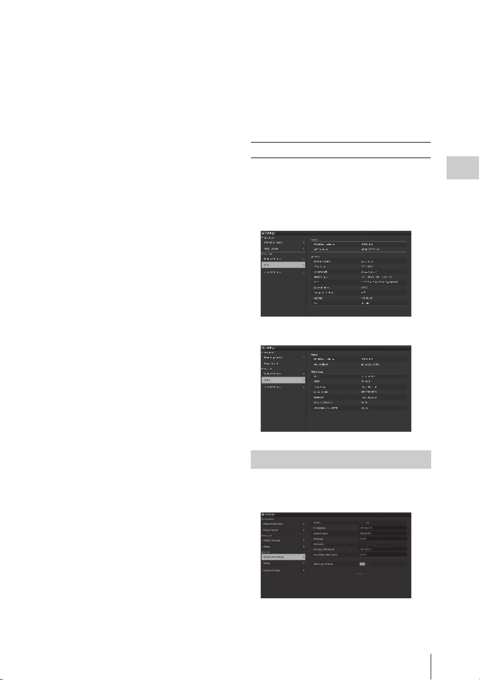
About the Web Menu
83
Recording
“DHCP”
Set the DHCP setting.
When you set to “On,” the IP address is assigned
to the camcorder automatically.
To assign the IP address to the camcorder
manually, set to “Off.”
“IP Address”
Input the IP address of the camcorder. This
setting is available only when “DHCP” is set to
“Off.”
“Subnet mask”
Input the subnet mask of the camcorder. This
setting is available only when “DHCP” is set to
“Off.”
“Gateway”
Input the default gateway for the access point.
This setting is available only when “DHCP” is set
to “Off.”
“DNS Auto”
Set to acquire DNS automatically.
When set to “On,” the DNS server address is
automatically acquired.
“Primary DNS Server”
Input the primary DNS server for the access
point. This setting is available only when “DNS
Auto” is set to “Off.”
“Secondary DNS Server”
Input the secondary DNS server for the access
point. This setting is available only when “DNS
Auto” is set to “Off.”
“Submit”
Confirms the wireless LAN settings.
To connect to the access point in the station
mode without the WPS function
1 Connect the device to the camcorder in
the access point mode (page 63).
2 Set the items on the “Station Settings”
screen.
Perform settings in accordance with the
access point settings.
For details about the access point settings,
see the operating instructions of the access
point.
3 Touch “Submit.”
The set items are confirmed.
4 Select “Access Point” for “Network
Mode” in the NETWORK SET menu
(page 124).
The camcorder starts connecting in the
station mode. Access the camcorder from the
device by performing procedure from step 8
of “Connecting to the access point with the
WPS function” (page 65).
Checking the wireless LAN settings
Display the screen for checking the wireless LAN
settings by touching “Wireless LAN” > “Status.”
The displayed items differ depending on the
wireless LAN mode of the camcorder.
Access point mode
Station mode
You can perform the settings for connecting to a
wired LAN.
Wired LAN Settings

About the Web Menu
84
Recording
“DHCP”
Set the DHCP setting.
When you set to “On,” the IP address is assigned
to the camcorder automatically.
To assign the IP address to the camcorder
manually, set to “Off.”
“IP Address”
Input the IP address of the camcorder. This
setting is available only when “DHCP” is set to
“Off.”
“Subnet mask”
Input the subnet mask of the camcorder. This
setting is available only when “DHCP” is set to
“Off.”
“Gateway”
Input the default gateway for the access point.
This setting is available only when “DHCP” is set
to “Off.”
“DNS Auto”
Set the DNS automatic acquisition function.
The DNS server address is acquired automatically
by setting to “On.”
“Primary DNS Server”
Input the primary DNS server for the access
point. This setting is available only when
“DHCP” is set to “Off.”
“Secondary DNS Server”
Input the secondary DNS server for the access
point. This setting is available only when
“DHCP” is set to “Off.”
“Web/Cam Remote”
Set the access permission for the Web menu of
the camcorder or the Wi-Fi remote commander of
the camcorder. The access is permitted by setting
to on.
Note
We recommend that “Web/Cam Remote” is set to
on while wired LAN network is not connected to
the Internet to prevent unauthorized access. If
connecting to the Internet, be sure to confirm that
the connected network is protected securely.
“Submit”
Determines the wired LAN settings.
Checking the wired LAN settings
Display the screen for checking the wired LAN
settings by touching “Wired LAN” > “Status.”
You can register the server for uploading a proxy
file or an original file that is recorded on the
camcorder, or change the server setting that is
registered.
“Auto Upload On/Off”
When “Auto Upload On/Off” is set to “On” and
the camcorder is connected to the Internet, the
camcorder automatically uploads a proxy file to
the server that is set to the default server at
“Upload Settings” after recording.
“Sony Ci” is set for the server as the default.
Sony Ci is “Media Cloud Services” that is
provided by Sony. You can upload files to the
Sony cloud service, Sony Ci.
Note
To use Sony Ci, registration is required.
For more details, please visit www.SonyMCS.com/
wireless
Upload Settings
Select the server.
Register the server.
Change the
server settings.
Delete the registered
server.
Turn the auto upload
function on/off.
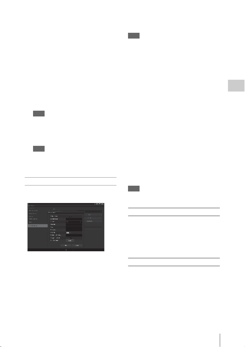
About the Web Menu
85
Recording
To register “Sony Ci”
1 Make sure that “Sony Ci” is displayed
on the “Upload Settings” screen, then
touch “Edit.”
The setting screen for Sony Ci appears.
2 Input the user name in “User” and
password in “Password.”
For more details, please visit
www.SonyMCS.com/wireless
3 Touch “Link.”
After a few moments, the completion
message appears.
Note
“Link” is the operation to associate the user with the
camcorder. To perform “Link,” you need to connect
the camcorder to the Internet.
4 Touch “OK.”
Note
After registering with Sony Ci, “Unlink” will
appear on the setting screen. If you touch “Unlink,”
the current user account will be unlinked, and you
can link with a different user account.
Register the server for uploading
The setting screen appears by touching “Create
New.”
The setting is applied by touching “OK.” To
cancel, touch “Cancel.”
“Default Server”
When you set to “On,” the server takes priority
for displaying the server name on the list when
uploading.
“Display Name”
Input the server name that is displayed on the list.
“Service”
Displays the server type.
“FTP”: FTP server
“Host Name”
Input the address of the server.
Note
If using a port other than the default Port 21, add “:123”
(example) after the address.
“User”
Input the user name of the server.
“Password”
Input the password of the server.
“PASV Mode”
Turn the PASV mode on/off.
“Destination Directory”
Specify the directory for uploading.
If illegal characters are input as a directory name,
the directory is not generated and a file is
uploaded to the directory directly under the target
directory.
“Using Secure Protocol”
Set whether to perform secure FTP uploading.
“Load Certification”
Reads the CA certificate.
* Format the certificate that is read in PEM format and
store it on the root directory of an SD card with the file
name, “certification.pem.”
“Clear Certification”
Clear the CA certificate.
Note
Using FTPS is recommended because FTP
communications are not encrypted.
Changing the registered server settings
Touch “Edit” after selecting the server for which
you want to change the settings on the “Upload
Settings” screen. Change the settings on the
screen for changing the settings.
For details about the setting items, see “Register
the server for uploading” (page 85).
Deleting the registered server
Touch “Delete” after selecting the server that you
want to delete on the “Upload Settings” screen.
When the confirmation screen appears, touch
“OK.” The selected server is deleted and the
display returns to the previous screen.

About the Web Menu
86
Recording
Set “Auto upload” to “On” to automatically start
transferring the file that is stored on an SD card
after recording.
When the camcorder records the proxy file that
inherits the information and recording duration
from the original based on the planning metadata,
a folder is created based on the information of the
<Title> tag in the planning metadata, and the file
is transferred into this folder. Also, the ID of the
media is added to the file name of the planning
metadata file and transferred.
Note
The target folder is named after the set folder
selected in “Selecting the File and Uploading”
(page 72). When a target folder is not set, it is
named in date format. To change the target folder,
perform settings in “Selecting the file and
uploading.”
If file transferring fails, the file transferring starts
where transferring failed when re-transferring.
Note
This function is available only on a server that is
compatible with the resume function.
You can check the list of the files to be uploaded,
the file that is being uploaded, cancel or start the
file upload, and delete the file from the file list.
The camcorder is compatible with the FTP
resume function (re-upload function for a file
whose transfer was suspended).
• “Total”: Progress of all the files to be uploaded.
• “Status”: Progress of the file that is currently
being uploaded.
• “Remain Time”: Estimated remaining time for
uploading.
• “Transfer data rate”: Transfer rate indication.
To cancel or start uploading, or delete a file from
the file list
1 Select the file on the list.
2 Touch at the upper right of the
screen.
Select the item.
• “Abort selected”: Cancels uploading the
selected file.
• “Delete from list”: Deletes the selected file
from the list.
• “Start selected”: Starts uploading the
selected file.
• “Select All”: Selects all files on the list.
• “Clear completed”: Deletes the list of all
the uploaded files.
If the camcorder detects an error, the error
message appears on the “Device Status” screen of
the device that is connected via wireless LAN
(page 79).
Starting file transferring
automatically after recording
Re-starting file transferring
(Resume function)
Checking the File Transferring
(Job List)
Error/Warning Indicator
Type Error/
warning ID
Description
Hard E01-003 Device Error
E01-004 3G/4G Device Error
E01-005 Firmware update error
AV E02-002 SDI Signal Error

About the Web Menu
87
Recording
* Sony Ci authentication is expired, or FTP server
authentication failed.
Communication
E03-001 Communication Error
E03-002 Not supported device
E03-003 File Transfer Error
E03-004 Firmware update error
E03-005
Authentication failed
*
E03-006 Server Capacity Over
E03-007
IP Address setting error
E03-008 Certification Error
Media W04-001 No Media
W04-002 Media Full
E04-003 Read Error
E04-004 Write Error (other
than Media Capacity
Over)
W04-005 Locked Media
W04-006 Clips Full (reached to
600 clips)
W04-008 Media Near Full
W04-009 Clips Near Full
W04-010 Last Clip Recording
E04-007 Not supported media
Type Error/
warning ID
Description
Thumbnail Screens
88
Playback
When you press the THUMBNAIL button (page 10), clips recorded on the SxS memory card are
displayed as thumbnails on the screen. If no clips are recorded on the card, a no-clip message is displayed.
You can start playback from the clip selected on the thumbnail screen. The playback picture can be seen
on the LCD monitor/EVF and external monitors.
Press the STOP/CAM button (page 10) to exit the thumbnail screen and return to the recording screen.
Note
Even if the SxS memory card contains a mixture of HD and SD clips, the normal thumbnail screen shows only clips of
the mode selected in “HD/SD” in “System” (page 133) of the OTHERS menu.
To display all recorded clips regardless of the HD/SD Mode, switch the screen to the All-Clip thumbnail screen (page 89).
Data for the clip selected with the cursor are displayed at the bottom of the screen.
1. Thumbnail
In UDF, exFAT, and FAT HD Mode: The
thumbnail image for each clip is an index frame
from the clip. When recording, the first frame of
a clip is automatically set as the index frame.
This frame can be adjusted (page 97). If the clip
is locked or is set with an OK mark, the lock
mark is displayed.
In FAT SD mode: The thumbnail image for each
clip is the first frame of the clip. If the file was
split into multiple parts because its file size
exceeded 2 GB, the take mark is displayed.
Split files can be viewed via the EXPAND CLIP
screen (page 95).
2. Date and starting time of recording
3. Clip name
In FAT SD Mode, if the file was split into
multiple parts because its file size exceeded 2
GB, the segment number is displayed after the
name, separated with a slash.
Playback
Thumbnail Screens
Configuration of the Thumbnail Screen
01 / JAN / 2009
10:53
S&Q 29 / 24
JPAN0011
(
1
)
HQ
1920 / 23.9P MP4
Current clip No./ Total number of clips
Cursor
(yellow)
The icon of the current SxS memory card is highlighted, shading the nonselected
one. (If the card is write-protected, a lock icon is displayed to the left.)
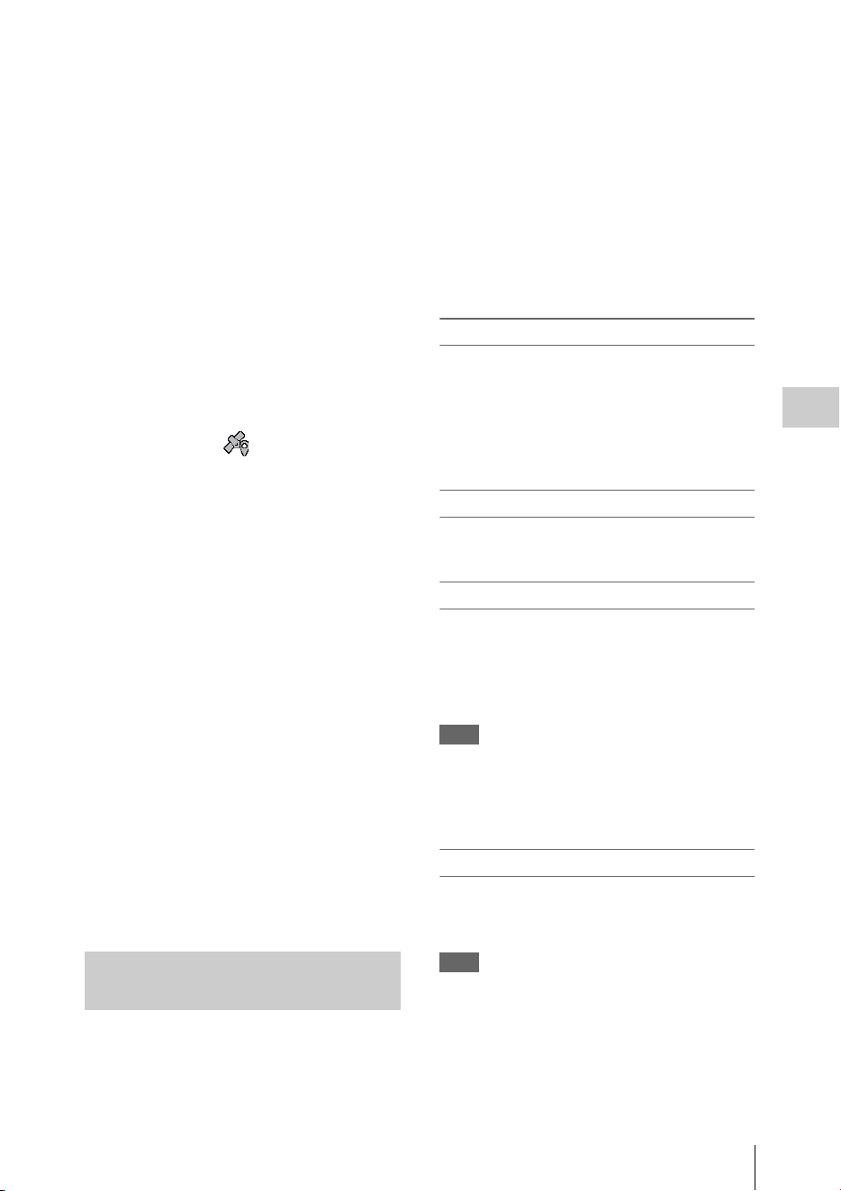
Thumbnail Screens
89
Playback
4. Lock mark (UDF, exFAT, and FAT HD
Mode)
UDF and exFAT: A lock mark appears if the
selected clip is locked.
FAT HD Mode: A lock mark appears if the
selected clip has an OK mark.
5. AV independent file icon (UDF, exFAT,
and FAT HD Mode)
Displayed only if the selected clip is an AV
independent file. This indicates that not all
operations and indications may be available,
because the clip may have been added manually
to the SxS file via a computer, etc., and there is
no management file for it.
6. Recording video format
7. GPS positioning information (exFAT/
XAVC format)
If GPS positioning information is contained in a
recorded clip, the icon appears.
8. File format
The file format (MXF, MP4, AVI) of the
selected clip is displayed. (This item is not
indicated when the recording mode is UDF HD
Mode or exFAT HD.)
9. Duration of the clip
10. Timecode
The timecode of the index frame is displayed.
11. OK/NG/KP mark (UDF, exFAT, and FAT
HD Mode)
UDF and exFAT: The mark is displayed if the
selected clip has an OK/NG/KP flag.
FAT HD Mode: The OK mark is displayed if the
selected clip has an OK mark.
12. Special recording information (UDF,
exFAT, and FAT HD Mode)
If the selected clip was recorded in a special
recording mode (Slow & Quick Motion, Interval
Recording, or Frame Recording), the mode is
displayed.
Clips recorded in Slow & Quick Motion display
the “Recording frame rate/playback frame rate
fps” to the right.
The type of thumbnail screen can be changed as
follows by pressing the THUMBNAIL button
(page 10).
UDF, exFAT
The normal thumbnail screen, OK/NG/KP/None
clip thumbnail screen, and All-Clip thumbnail
screen are cyclically displayed.
FAT HD Mode
The normal thumbnail screen, OK clip thumbnail
screen, and All-Clip thumbnail screen are
cyclically displayed.
FAT SD Mode
The normal thumbnail screen and All-Clip
thumbnail screen are alternately displayed.
OK/NG/KP/None-Clip thumbnail screen
Only the clips flagged OK/NG/KP—or clips with
no flag (“None”)—among the clips on the current
SxS memory card are displayed.
You can select the type of flag to display with
“Filter Clips” in “Clip” (page 134) of the
OTHERS menu.
OK-Clip thumbnail screen
Only the clips marked OK among the clips on the
current SxS memory card are displayed.
All-Clip thumbnail screen
The All-Clip thumbnail screen shows all clips on
the current SxS memory card regardless of the
HD or SD Mode, permitting you to check whether
the card contains any clips of another mode than
that currently selected.
Note
You cannot start playback from the All-Clip thumbnail
screen.
Press the THUMBNAIL button again to return to the
normal thumbnail screen, and playback and clip
operations are enabled.
Switching the SxS memory cards
When two memory cards are loaded, press the
SLOT SELECT button (page 12) to switch
memory cards.
Note
Card switching is enabled only when the thumbnail
screen is displayed or when an external input picture is
displayed by pressing the STOP/CAM button.
You cannot switch memory cards during playback.
Continuous playback of cards in slots A and B is not
possible.
Changing the Type of Thumbnail
Screen

Playing Clips
90
Playback
For playback operations, use the playback control
buttons on the handle (page 10). When the IR
Remote Commander is enabled, you can use its
playback control buttons instead (page 21).
1 Using the up/down/left/right buttons or
the jog dial, move the cursor to the
thumbnail image of the clip with which
you wish to start playback.
2 Press the PLAY/PAUSE button.
Playback starts from the beginning of the
selected clip.
Notes
• The playback picture may be momentarily distorted or
frozen between clips. The playback control buttons
and THUMBNAIL button do not function during this
condition.
• When you select a clip on the thumbnail screen and
start playback, the playback picture at the beginning of
the clip may be distorted. To start playback without
distortion, once pause playback after starting it, press
the PREV button to return to the top of the clip, then
restart playback.
Information displayed on the playback
screen
The following information is superimposed on
the playback picture.
1. Battery remaining/DC IN voltage
2. Playback mode
3. SxS memory card
A mark appears to the left if the SxS memory
card is write-protected.
4. Time data
The time data for the playback picture are
displayed. Each time you press the
DURATION/TC/U-BIT button, the indication
is switched between timecode (TCR) and user-
bit (UB) data.
5. Clip no./total number of clips
This is displayed for FAT. It is also displayed
for UDF and exFAT if “Find Mode” in “Clip”
(page 134) of the OTHERS menu is set to
“Clip.”
6. Clip no./total number of clips, essence
mark no./total number of essence marks
This is displayed for UDF and exFAT if “Find
Mode” in “Clip” (page 134) of the OTHERS
menu is set to “Rec Start.”
7. Audio levels
The audio levels for the recording are displayed.
Playing Clips
Playing the Selected and
Subsequent Clips in Sequence
TCR 00: 00:00:00
0011/ 03 00
120min B PLAY
CH1
CH2
12345
7

Clip Operations
91
Playback
In Normal playback mode, you can monitor the
recorded audio signals through the built-in
speaker (page 9) or connected headphones.
With the headphones connected to the headphone
connector (page 8), the built-in speaker is turned
off.
Press the VOLUME buttons (page 10) to adjust
the sound volume.
You can select audio channel(s) to be monitored
with “Audio Output” (page 116) of the AUDIO
SET menu.
To start playback from the top of the first clip
Press the PREV button and F REV button
simultaneously. The top of the first-recorded clip
on the memory card is cued up.
To start playback from the top of the last clip
Press the F FWD button and NEXT button
simultaneously. The top of the last-recorded clip
on the memory card is cued up.
In the same manner as in recording, you can add
shot marks to the clip during playback.
At the point where you wish to add a shot
mark, press the “Shot Mark1” or “Shot
Mark2” assigned button.
Notes
• No shot mark can be added if the memory card is write-
protected.
• No shot mark can be added to the first or last frame of
a clip.
During thumbnail screen playback, etc., you can
operate the clips or confirm and change the
subsidiary data for clips using the Clip Operation
menus. The corresponding Clip Operation menu
pops up on the screens as shown below when you
press the SEL/SET button or the jog dial.
Monitoring Audio
Cueing Up
Adding Shot Marks During
Playback (UDF, exFAT, and FAT HD
Mode)
Clip Operations
Clip Operation Menus
Thumbnail screen (page 92)
CANCEL
DISP CLIP INFO
OK MARK ADD (FAT only)
OK MARK DELETE (FAT only)
OK FLAG ADD (UDF and exFAT)
NG FLAG ADD (UDF and exFAT)
KEEP FLAG ADD (UDF and exFAT)
CLIP FLAG DELETE (UDF and exFAT)
LOCK CLIP (UDF and exFAT)
UNLOCK CLIP (UDF and exFAT)
COPY CLIP
DELETE CLIP
ALL MARKS
SHOT MARK1
SHOT MARK2
REC START MARK (UDF and exFAT)
EXPAND CLIP

Clip Operations
92
Playback
Note
Selectable menu items are limited in SD Mode.
Use the up/down/left/right buttons or the jog dial
to select a menu item, then press the SEL/SET
button or the jog dial.
Pressing the CANCEL button restores the
previous condition.
Selecting “CANCEL” from a Clip Operation
menu turns the Clip Operation menu off.
Notes
• While the camcorder is transferring the original file
partially (page 73), you cannot operate some of the
menus.
• When the SxS memory card is write-protected, some
operations are unavailable.
• There may be items that cannot be selected depending
on the status when the menu is displayed.
Clip Operation menu on the thumbnail
screen
Pressing the SEL/SET button or the jog dial with
the thumbnail screen (page 88) displayed calls the
Clip Operation menu for the clip at the cursor.
1)Effective with FAT HD Mode only.
2)Effective with UDF and exFAT only.
3)Effective with UDF, exFAT, and FAT HD Mode.
Expand Clip screen (page 96)
CANCEL
EXPAND (COARSE)
EXPAND (FINE)
PAUSE
SET INDEX PIC
SHOT MARK1 ADD
SHOT MARK2 ADD
SHOT MARK1 DEL
SHOT MARK2 DEL
DIVIDE CLIP (FAT only)
Shot Mark screen (page 97)
CANCEL
PAUSE
SET INDEX PIC
SHOT MARK1 DEL
SHOT MARK2 DEL
DIVIDE CLIP (FAT only)
Basic Operations of the Clip
Operation Menus
Item Function
DISP CLIP INFO Displays the clip’s information
screen (page 93).
OK MARK
ADD
1)
Adds an OK mark (page 94).
OK MARK
DELETE
1)
Deletes the OK mark (page 94).
OK FLAG
ADD
2)
Adds an OK flag (page 94).
NG FLAG
ADD
2)
Adds a NG flag (page 94).
KEEP FLAG
ADD
2)
Adds a KP flag (page 94).
CLIP FLAG
DELETE
2)
Deletes the flag (page 94).
LOCK CLIP
2)
Locks and protects a clip (page
94).
UNLOCK CLIP
2)
Unlocks a protected clip (page
94).
COPY CLIP Copies the clip to another SxS
memory card (page 94).
DELETE CLIP Deletes the clip (page 95).
ALL MARKS
3)
Displays thumbnails of all frames
with an essence mark recorded
(page 96).
SHOT MARK1
3)
Displays only thumbnails of
frames with shot mark 1 recorded
(page 96).
SHOT MARK2
3)
Displays only thumbnails of
frames with shot mark 2 recorded
(page 96).
REC START
MARK
Displays thumbnails of frames
with a Recording Start mark and
the first frames of clips without
Recording Start marks (page 96).
EXPAND CLIP Switches to the EXPAND CLIP
screen (page 95).
Clip Operations
93
Playback
Select “DISP CLIP INFO” from a Clip Operation menu.
1. Image of the current clip
2. Image of the previous clip
Press the PREV button to switch to the clip info
screen of the previous clip.
In FAT SD Mode, the previous segment of a
segmented clip is displayed.
3. Image of the next clip
Press the NEXT button to switch to the clip info
screen of the next clip.
In FAT SD Mode, the next segment of a
segmented clip is displayed.
4. Clip name
For a clip name of 12 characters or longer, only
the first 5 and last 5 characters of the name are
displayed. To check the non-displayed block of
the name, press the jog dial or the SEL/SET
button to display the entire clip name (Long-
Display mode). Press the jog dial or the SEL/
SET button again to cancel Long-Display mode.
Long-Display mode is also canceled by
switching to the previous or next clip with the
PREV or NEXT button.
In FAT SD Mode, if the file was split into
multiple parts because its file size exceeded 2
GB, the segment number is displayed after the
name, separated with a slash.
5. Lock mark (UDF, exFAT, and FAT HD
Mode)
UDF and exFAT: A lock mark appears if the
selected clip is locked.
FAT HD Mode: A lock mark appears if the
selected clip has an OK mark.
6. OK/NG/KP mark (UDF, exFAT, and FAT
HD Mode)
UDF and exFAT: The mark is displayed if the
selected clip has an OK/NG/KP flag.
FAT HD Mode: The OK mark is displayed if the
selected clip has an OK mark.
7. GPS positioning information (exFAT/
XAVC format)
If GPS positioning information is contained in a
recorded clip, the icon appears.
8. Date and starting time of recording
9. File format
The file format (MXF, MP4, AVI) of the
selected clip is displayed.
10. Special recording information (UDF,
exFAT, and FAT HD Mode)
If the selected clip was recorded in a special
recording mode (Slow & Quick Motion, Interval
Recording, or Frame Recording), the mode is
displayed.
Clips recorded in Slow & Quick Motion display
the “Recording frame rate/playback frame rate
fps” to the right.
11. Timecode of the displayed frame
12. Timecode at the recording starting point
13. Timecode at the recording ending point
14. Duration of the clip
15. Recorded audio channels
16. Recorded video format
Displaying the Detailed Information of a Clip
OK
OK
120
m
in CLIP
I NFO
0011 / 0300
PREV
CLIP NEXT
CLIP
JPAN0011
(
1
)
01 / JAN / 2009
10:53
HQ
1920 / 23.9P MP4
S
&
Q
M
otion
29/24fps
TCR
00:05:00:02
TCR
00:05:00:00
STR
TCR
00:08:19:23
END
DUR
00:03:20:00
CH1/2/3/4/5/6/7/8
1
2
3
4
5
6
7
8
9
10
16
11
12
13
14
15

Clip Operations
94
Playback
You can add an OK/NG/KP flag to clips recorded
in UDF or exFAT. By adding flags, you can set
the camcorder to display only clips with certain
flag settings on the thumbnail screen (OK/NG/
KP/None-Clip thumbnail screen) (page 89).
When adding a flag, you can select from OK
FLAG ADD, NG FLAG ADD, and KEEP FLAG
ADD in the Clip Operation menu (page 92) on the
thumbnail screen. When deleting a flag, select
CLIP FLAG DELETE.
Note
Flagged clips are not protected. To protect clips from
deletion, select LOCK CLIP in the Clip Operation menu
(page 92) on the thumbnail screen. To remove the
protection, select UNLOCK CLIP.
By adding an OK mark to clips recorded in FAT
HD Mode, you can set the camcorder to display
only the necessary clips on the thumbnail screen
(page 89). Clips with an OK mark added are
blocked from being deleted or segmented. To
delete or segment them, remove the OK mark.
From the thumbnail screen Clip Operation menu
(page 92), you can select OK MARK ADD to add
an OK mark, or OK MARK DELETE to delete
the OK mark.
You can copy clips on an SxS memory card to
another SxS memory card.
Each clip is copied with the same name to the
destination SxS memory card.
Notes
• If there is another clip having the same name on the
destination SxS memory card, the clip is copied under
a name adding a single-digit number in parentheses to
the end of the original clip name.
The parenthetical number is the minimum value that
does not exist in the destination memory card.
Examples:
ABCD0002(1) if ABCD0002 exists
ABCD0002(2) if ABCD0002(1) exists
ABCD0005(4) if ABCD0005(3) exists
• When using FAT, you cannot copy a file 10 times or
more if clips with the same clip name followed by
parenthetical numbers (1) to (9) already exist on the
card.
• When using UDF or exFAT, you cannot copy a file
1000 times or more if clips with the same clip name
followed by parenthetical numbers (1) to (999) already
exist on the card.
• A warning message is displayed if there is not
sufficient space on the destination SxS memory card.
Replace the SxS memory card with one with sufficient
space.
• When copying an SxS memory card on which multiple
clips have been recorded, copying all clips to the end
may not be achieved, even if the destination card has
the same capacity as the source card, depending on
usage conditions, memory characteristics, etc.
Copying a specified clip
You can copy a clip selected on the thumbnail
screen to another SxS memory card.
Select “COPY CLIP” from the Clip Operation
menu.
Copying clips collectively
By using the Setup menu, you can copy clips on
an SxS memory card collectively to another SxS
memory card.
If the memory card contains clips of both HD and
SD Mode, only the clips of the currently selected
mode are copied. This may be convenient when
you wish to extract clips of the same mode only.
Select “Clips” in “Copy All” (page 135) of the
OTHERS menu.
Adding/Deleting a Flag (UDF and
exFAT)
Adding/Deleting the OK Mark (FAT
HD Mode Only)
Copying Clips
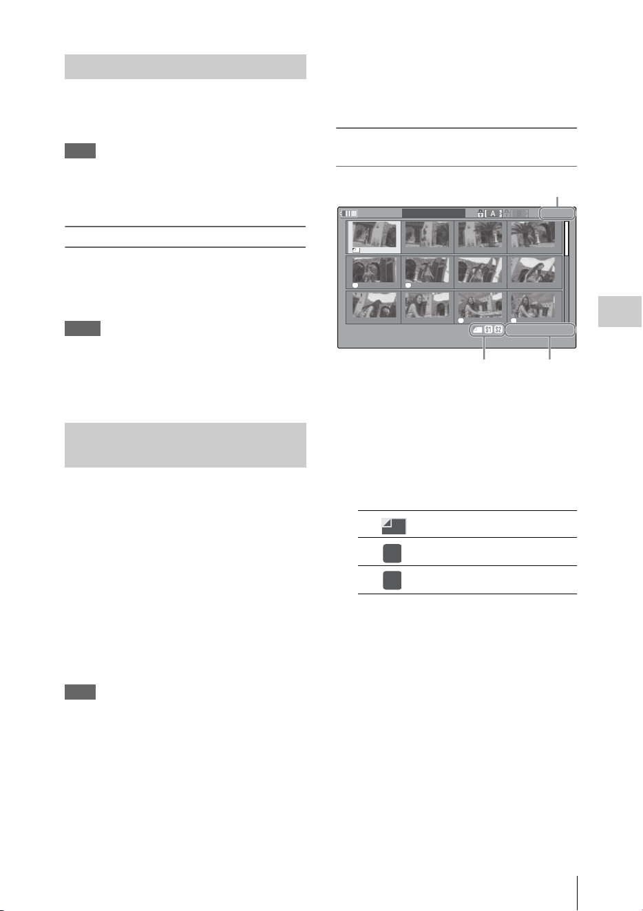
Clip Operations
95
Playback
You can delete clips from the SxS memory card.
Select “DELETE CLIP” from the Clip Operation
menu.
Note
Clips with an OK mark and flagged clips set to LOCK
CLIP cannot be deleted.
To delete them, release the OK mark or the LOCK CLIP
setting before performing the delete operation.
Deleting clips collectively
By using the Setup menu, you can delete clips
from an SxS memory card collectively.
Select “All Clips DEL” in “Clip” (page 134) of
the OTHERS menu.
Notes
• If the memory card contains clips of both HD and SD
Mode, only the clips of the currently selected mode are
deleted.
• Clips with an OK mark and flagged clips set to LOCK
CLIP cannot be deleted.
In UDF, exFAT, and FAT HD Mode, the
EXPAND CLIP screen permits you to divide a
clip into 12 blocks of equal duration and show a
thumbnail image of the first frame of each block
on the screen.
In FAT SD Mode, the EXPAND CLIP screen
shows the thumbnail images of the first frames of
the segment files only for a clip segmented
because its file size exceeded 2 GB.
This helps you to quickly cue up to a desired
scene in a clip of long duration.
You can display the EXPAND CLIP screen by
selecting the clip on the thumbnail screen.
Note
If GPS positioning information is contained in a recorded
clip, no icon appears on the EXPAND CLIP screen.
1 Select a clip on the thumbnail screen,
then press the SEL/SET button or the
jog dial.
The corresponding Clip Operation menu
pops up.
2 Select “EXPAND CLIP.”
The EXPAND CLIP screen appears for the
clip that you selected on the thumbnail
screen.
EXPAND CLIP screen in UDF, exFAT, and
FAT HD Mode
Detailed information for the clip is displayed at
the bottom of the screen.
The items other than the following are the same as
those on the normal thumbnail screen (page 88):
1. Frame information
The following icons show the marking for the
frame at the cursor.
The same icons may also be displayed below the
thumbnail image of each frame. If the frame has
multiple markings, one of the icons is displayed,
in the priority order of index frame, shot mark 1,
and shot mark 2.
2. Timecode indication
The timecode of the frame at the cursor is
displayed.
Deleting Clips
Displaying the EXPAND CLIP
Screen
Index frame
Frame with shot mark 1 added
Frame with shot mark 2 added
S1 S2
S2 S1
120
m
in
EXPAND
CLIP
01:10:20:00 01:10:30:00 01:10:40:00 01:10:50:00
01:11:00:00 01:11:10:00 01:11:20:00 01:11:30:00
01:11:40:00 01:11:50:00 01:12:00:00 01:12:10:00
0000123
01 / JAN / 2009
10:53
S
&
Q
29 / 24
JPAN0011
(
1
)
HQ
1920 / 23.9P
TCR
01:10:20: 00
DUR
00:03:19:23
2
1
Current frame number
S1
S2
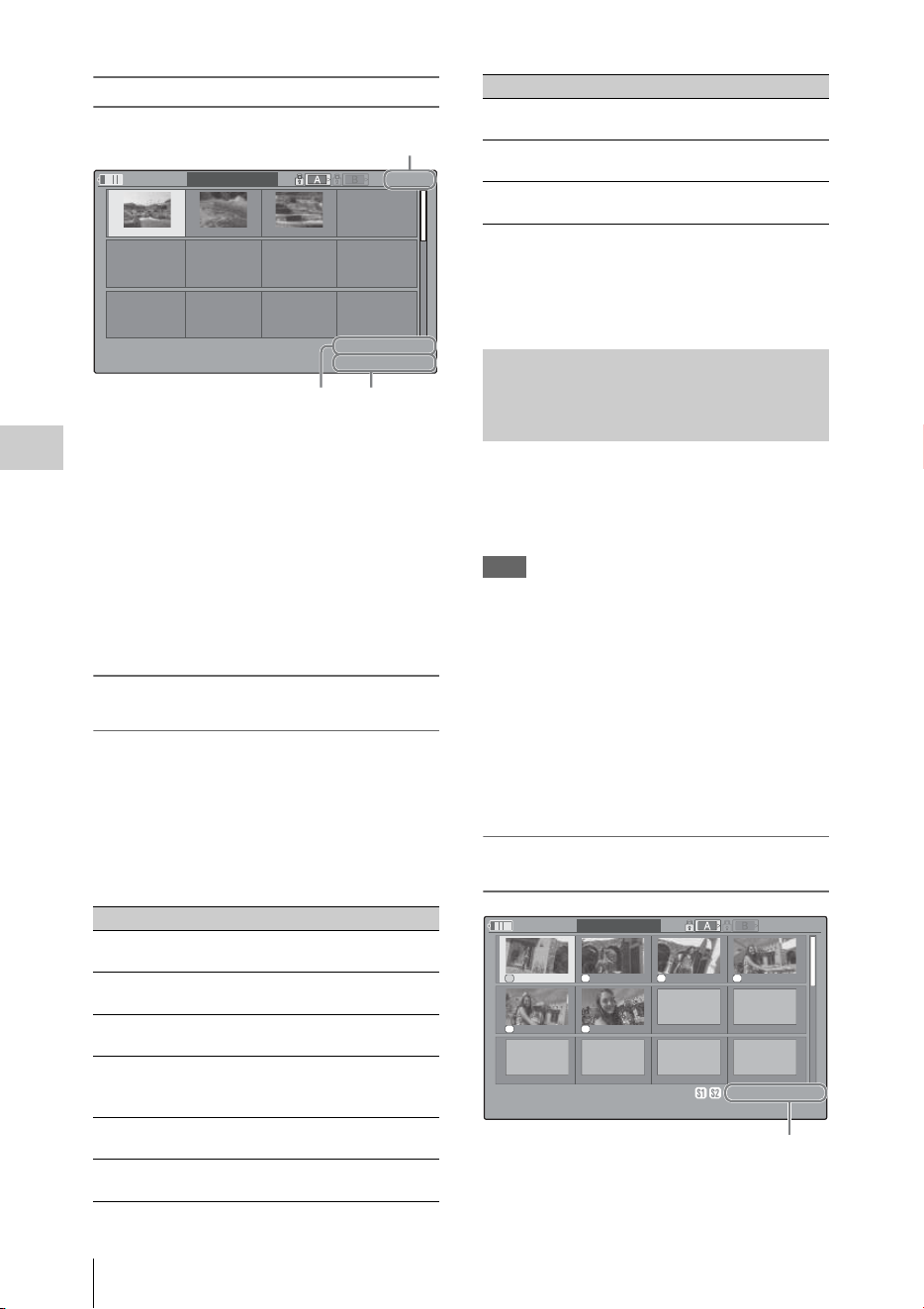
Clip Operations
96
Playback
EXPAND CLIP screen in FAT SD Mode
Detailed information for the clip is displayed at
the bottom of the screen.
The items other than the following are the same as
those on the normal thumbnail screen (page 88):
1. Timecode indication
The timecode of the segmentation file at the
cursor is displayed.
2. Duration
The duration of the segmentation file at the
cursor is displayed.
Clip Operation menu on the EXPAND CLIP
screen
UDF, exFAT, and FAT HD Mode
When you select a frame on the EXPAND CLIP
screen and press the SEL/SET button or the jog
dial, the Clip Operation menu pops up to enable
operations such as displaying more detailed split
displays and saving the frames after the selected
frame as different clip.
FAT SD Mode
You can select “PAUSE” only on the EXPAND
CLIP screen in FAT SD Mode.
When one or more shot marks or recording start
marks are recorded for a single clip, you can
display only frames with those marks as
thumbnail images on the screen.
Note
If GPS positioning information is contained in a recorded
clip, no icon appears on the SHOT MARK screen.
1 Select a clip on the thumbnail screen,
then press the SEL/SET button or the
jog dial.
2 Select ALL MARK, SHOT MARK1,
SHOT MARK2, or REC START
MARK from the Clip Operation menu
(page 92).
SHOT MARK screen example (when ALL
MARKS is selected)
The detailed information of the clip is displayed
at the bottom of the screen.
Item Function
EXPAND
(COARSE)
To decrease the number of
partitions of the clip
EXPAND
(FINE)
To increase the number of
partitions of the clip
PAUSE To set to Pause mode at the
selected frame
SET INDEX PIC To specify the selected frame for
the index frame of the clip (page
97)
SHOT MARK1
ADD
To add shot mark 1 to the selected
frame (page 97)
SHOT MARK2
ADD
To add shot mark 2 to the selected
frame (page 97)
120
m
in
EXPAND
CLIP
00:00:00:00 00:09:30:00 00:19:00:00
0000001
01 / JAN /2009
10:53
JPAN0011
_01
DVC
A
M
29.9PsF
SQ
TCR
00:00:00:00
DUR
00:09:30:00
21
Current frame number
SHOT MARK1
DEL
To delete shot mark 1 from the
selected frame (page 97)
SHOT MARK2
DEL
To delete shot mark 2 from the
selected frame (page 97)
DIVIDE CLIP To divide the clip into two clips at
the selected frame (page 97)
Displaying the SHOT MARK
Screen (UDF, exFAT, and FAT HD
Mode)
Item Function
S1 S2 S2 S1
S1 S
1
120
m
in
S
H
O
TSHOT MARK1
01:10:20:00 01:10:30:00 01:10:40:00 01:10:50:00
01:11:00:00 01:11:10:00
-
-
-
-
-
-
-
-
-
-
-
-
-
-
-
-
-
-
0031 /0031
01 / JAN / 2009
10:53
S
&
Q
29 / 24
JPAN0011
(
1
)
HQ
1920 / 23.9P
TCR
01:12:00: 00
DUR
00:03:19:23
1

Clip Operations
97
Playback
The items other than the following are the same as
those on the EXPAND CLIP screen (page 95) in
UDF, exFAT, and FAT HD mode:
1. Timecode indication
The timecode of the frame at the cursor on the
SHOT MARK screen is displayed.
Move the cursor to the first/last frame
When the cursor is at a user-designated position,
press the F REV and PREV buttons
simultaneously to move the cursor the first frame.
Press the F FWD and NEXT buttons
simultaneously to move the cursor to the last
frame.
Switch to the clip shot mark screen for a different
clip
When the cursor is at the first frame for a clip,
press the PREV or up button, or turn the jog dial
up to switch to the previous displayable clip shot
mark screen.
When the cursor is at the last frame for a clip,
press the NEXT or down button, or turn the jog
dial down to switch to the next displayable clip
shot mark screen.
Clip Operation menu on the SHOT MARK
screen
When you select a frame on the SHOT MARK
screen and press the SEL/SET button or the jog
dial, the Clip Operation menu pops up to permit
you further operations.
Adding a shot mark in Pause mode
Select “SHOT MARK1 ADD” or “SHOT
MARK2 ADD” from the Clip Operation menu.
Adding a shot mark on the EXPAND CLIP
screen
Select “SHOT MARK1 ADD” or “SHOT
MARK2 ADD” from the Clip Operation menu.
Deleting a shot mark
You can delete shot marks on the EXPAND CLIP
screen (page 95) or on the SHOT MARK screen
(page 96).
Select “SHOT MARK1 DEL” or “SHOT
MARK2 DEL” from the Clip Operation menu.
You can change the index frame to another frame
you selected on the EXPAND CLIP screen (page
95) or the SHOT MARK screen (page 96).
Select “SET INDEX PIC” from the Clip
Operation menu.
Note
Even if you specify a frame other than the top frame for
the index frame, playback always begins from the top
frame when you start it from the thumbnail screen.
In FAT HD Mode, you can divide a clip into two
different clips at the frame you select on the
EXPAND CLIP screen (page 95) or the SHOT
MARK screen (page 96).
Select “DIVIDE CLIP” from the Clip Operation
menu.
The first 4 characters of the original clip name are
carried on, continuing to the last number on the
memory card by the second 4 numerics.
Example: If you divide a clip named ABCD0002
into two clips under the condition where a
new clip will be named EFGH0100, clip
ABCD0100 and clip ABCD0101 are created.
Note
If the remaining space on the memory card is insufficient
for divided clips, a message informing you of it appears.
Item Function
PAUSE To set to Pause mode at the selected
frame
SET INDEX PIC To specify the selected frame for the
index frame of the clip (page 97)
SHOT MARK1
DEL
To delete the shot mark 1 from the
selected frame (page 97)
SHOT MARK2
DEL
To delete the shot mark 2 from the
selected frame (page 97)
DIVIDE CLIP To divide the clip into two clips at
the selected frame (page 97) (FAT
HD mode Only)
Adding/Deleting Shot Marks (UDF,
exFAT, and FAT HD Mode)
Changing the Index Frame (UDF,
exFAT, and FAT HD Mode)
Dividing a Clip (FAT HD Mode
Only)

Showing the Status Screens
98
Playback
Press the STATUS button (page 10) to display
status screens on the LCD monitor/EVF screen/
external video monitor.
Use the up/down buttons (page 10) or the jog dial
(page 11) to perform operations and switch the
screens in sequence.
When you press the STATUS button again, the
status screen display is canceled.
For connections of an external monitor, see
“Connecting External Monitors and Recording
Devices” on page 138.
White Bal: White balance status
Gain: GAIN switch settings
The gain values of the positions L, M, and H of
the GAIN switch assigned of the CAMERA SET
menu are displayed.
Handle Zoom Speed: Handle zoom speed
settings
The zoom speed that is set at “High”/“Low” of
“Zoom Speed” (page 109) of the CAMERA SET
menu are displayed.
Zebra: Zebra status
Skin Tone Detail: Skin-tone detail status
The current status (On or Off) of “Setting” of
“Skin Tone Detail” of the PICTURE PROFILE
menu is displayed.
Picture Profile: Picture Profile selection status
The selected Picture Profile number and name are
displayed. (If Picture Profile is off, “Off” is
displayed.)
Output CH: External output/headphone output
Depending on the setting of “Output CH” in
“Audio Output” of the AUDIO SET menu and the
setting of “Monitor CH,” the audio channel(s)
external output and headphones output is
displayed as follows.
• CH-1: When left/right are CH-1
• CH-2: When left/right are CH-2
• CH-3: When left/right are CH-3
• CH-4: When left/right are CH-4
• CH-1/CH-2: When left is CH-1 and right is CH-
2 (stereo)
• CH-3/CH-4: When left is CH-3 and right is CH-
4 (stereo)
• CH-1+CH-2: When both left and right are CH-
1 and CH-2 (monaural)
• CH-3+CH-4: When both left and right are CH-
3 and CH-4 (monaural)
Speaker: Speaker output
The audio channel(s) output to the internal
speaker is displayed.
As the speaker is monaural, CH-1+CH-2 or CH-
3+CH-4 is displayed when “Monitor CH” is set to
Showing the Status
Screens
Camera Status Screen
Display Contents
B The color temperature stored in white
memory B is indicated.
A The color temperature stored in white
memory A is indicated.
PRST The color temperature set as the preset
white is indicated. The color temperature of
preset white can be changed using the
PICTURE PROFILE menu.
Display Contents
L Zoom speed that is set at “Low” of “Zoom
Speed.”
H Zoom speed that is set at “High” of “Zoom
Speed.”
Display Contents
1 “On” is displayed and the setting of
“Zebra1 Level” in “Zebra” of the LCD/VF
SET menu is displayed to the right when
“Zebra Select” in “Zebra” of the LCD/VF
SET menu is set to “1” or “Both” and you
set the Zebra function to “On.” If the Zebra
function is set to “Off” or “Zebra Select” is
set to “2,” “Off” appears.
2 “On” is displayed when “Zebra Select” in
“Zebra” of the LCD/VF SET menu is set to
“2” or “Both” and you set the Zebra
function to “On.” If the Zebra function is
set to “Off” or “Zebra Select” is set to “1,”
“Off” appears.
Audio Status Screen

Showing the Status Screens
99
Playback
stereo. With non-stereo settings, the setting of
“Monitor CH” in “Audio Output” of the AUDIO
SET menu is displayed as it is.
CH-1/CH-2/CH-3/CH-4: Audio level meters
The 4-channel audio level meters (2 meters when
using 2-channel settings) and input source are
displayed.
While recording (or standing by to record), the
level of the audio inputs (the EE audio levels) are
displayed. During playback, the audio playback
level is displayed according to the setting of
“Output CH” in “Audio Output” of the AUDIO
SET menu.
If audio is input from the i.LINK (HDV/DV)
connector while displaying thumbnails, while
playback is stopped, or while recording an
external signal, the audio input level is displayed.
In this case, the leftmost channels that are
displayed are CH-1 and CH-2, regardless of the
setting of “Output CH” in “Audio Output” of the
AUDIO SET menu.
Wind Filter
The “On”/“Off” setting of Wind Filter is
displayed to the right of each input source. Wind
Filter settings can be made from “Wind Filter
CH1” to “Wind Filter CH4” in “Audio Input” of
the AUDIO SET menu.
Video Format
Video Format: Video format setting
The number of vertical lines, frame rate, and scan
format (i/P) of the video format set in “Format” in
“System” of the OTHERS menu are displayed.
Rec Mode: Recording bit rate
The video format set in “Format” in “System” of
the OTHERS menu is displayed.
3G SDI OUT Level: Data mapping method of the
3G SDI signal
The data mapping method of the 3G SDI signal
set in “3G SDI OUT Level A/B” of the VIDEO
SET menu is displayed.
SDI Output: Output for SDI
The “SDI” setting in “SDI/HDMI/i.LINK I/O
Select” of the VIDEO SET menu is displayed.
HDMI Output: Output for HDMI
The “HDMI” setting in “SDI/HDMI/i.LINK I/O
Select” of the VIDEO SET menu is displayed.
i.LINK I/O: Input and output for i.LINK
The “i.LINK” setting in “SDI/HDMI/i.LINK I/O
Select” of the VIDEO SET menu is displayed.
Down Converter: SD output down-converter
setting
In HD Mode, the “Down Converter” setting
(Squeeze, Letterbox, Edge Crop) of the VIDEO
SET menu is displayed.
In SD Mode, “Edge Crop” is displayed when EC
(Edge Crop) in “Format” in “System” of the
OTHERS menu is selected, and “Squeeze” is
displayed when SQ (Squeeze) in “Format” in
“System” of the OTHERS menu is selected.
23.98P Output: 23.98P output mode
The “23.98P Output” setting (23.98PsF, 59.94i
(2-3 Pull Down)) of the VIDEO SET menu is
displayed.
Assign Button: Assignable button statuses
The functions assigned with the “Assign Button”
of the OTHERS menu to the respective
assignable buttons are displayed.
IR Remote: IR Remote Commander status
The “IR Remote” setting of the OTHERS menu is
displayed.
Network Remote: Wi-Fi Remote Commander
status
The “Network Remote” setting of the
NETWORK SET menu is displayed.
Battery: Battery charge remaining
The remaining charge level of the mounted
battery pack is displayed.
Charge Count: Repeated charge times
The number of times that the mounted battery
pack has been charged is displayed.
HDD A/HDD B: Battery remaining of PHU-220R
units
When professional hard disk units are connected,
the remaining power levels of the batteries of the
professional hard disk units connected via the
respective card slots are displayed.
Video Status Screen
Button/Remote Status Screen
Battery/Media Status Screen

Showing the Status Screens
100
Playback
Media A/Media B: Remaining space, available
recording time, and estimated service life
(rewriting limit)
The remaining space of the SxS memory cards in
the respective card slots is indicated on the
meters.
At the right, the available time for recording if
done at the current bit rate is displayed, in
minutes.
The time indication will be “- - min” if no SxS
memory card or an invalid card is in the slot.
If the card is write-protected, a icon is shown
to the right of the time indication.
The Life value is displayed only for an SxS
memory card which supports the life value
indication. It indicates the estimated remaining
usable period of the card (virgin status as 100%).
If an alarm is generated, make a backup of the
card as soon as possible and replace it with a new
card.
SD Card: Remaining space and available
recording time of an SD card
The remaining space of the SD card in the SD
card slot is indicated on the meters.
At the right, the available time for recording is
displayed.
The time indication will be “- - min” if no SD card
or an invalid card is in the SD card slot.
GPS: GPS positioning status
Displays the positioning status for the current
GPS signal as icons.
DOP: Horizontal dilution of precision
Displays positioning accuracy.
Displays “---” when there is no positioning
information.
LATITUDE: Latitude
Displays latitude information.
Displays “---” when there is no positioning
information.
LONGITUDE: Longitude
Displays longitude information.
Displays “---” when there is no positioning
information.
ALTITUDE: Altitude
Displays altitude information.
Displays “---” when there is no positioning
information.
CALC: Positioning date and time
Displays time and date when positioning
information is obtained.
Displays according to the setting in “Clock Set”
of the OTHERS menu.
Displays “---” when there is no positioning
information.
REAL: Current data and time
Displays current data and time of the camcorder.
Displays according to the setting in “Clock Set”
of the OTHERS menu.
TIME ZONE: Time zone
Displays the setting in “Time Zone” of the
OTHERS menu.
Notes
• While “GPS” of the OTHERS menu is set to “Off” and
during playing back, “---” is displayed except for
“REAL” and “TIME ZONE.”
• Right after “GPS” of the OTHERS menu is set to
“On”, “---” is displayed except for “REAL” and
“TIME ZONE” until positioning information is
obtained.
• When the positioning status changes to the detecting
status, the last obtained positioning information is
displayed. If information is not obtained for some
items, “---” may be displayed for the items.
You can display file information that was recently
loaded on the list in the loaded order. Up to 9 files
of the file information can be displayed (up to 3
files each for Camera Data, User Data, or PP
Data).
Load Date/Time: Loaded time and date
The file information is listed in the loaded order.
The time and date are displayed by the internal
clock of the camcorder.
Type: File type
The type of the loaded file (Camera Data, User
Data, PP Data) is displayed.
Src: Media type
The type of the media from which the file is
loaded is displayed.
File ID: File name
When the loaded file is named in “File ID,” the
file name is displayed.
For details about naming in “File ID,” see
“Naming the stored file” (page 55).
GPS positioning status indication
RECENT FILES Status Screen

Overview of the Setup Menus
101
Menu Configuration and Detailed Settings
Press the MENU button to display setup menus
on the LCD monitor/EVF screen with settings
necessary for recording and playback. (You can
also display setup menus on an external monitor.)
Set items by selecting them from the following
menus.
USER menu: Placing the menu items in your
favorite order (page 105).
USER MENU CUSTOMIZE menu: Setting the
USER menu (page 105).
CAMERA SET menu: For setting items related
to recording other than those for picture quality.
(For picture quality-related items, use the
PICTURE PROFILE menu (page 47).)
AUDIO SET menu: For setting audio-related
items.
VIDEO SET menu: For setting video output-
related items.
LCD/VF SET menu: For setting items related to
the LCD monitor/EVF display.
TC/UB SET menu: For setting items related to
timecodes and user bits.
NETWORK SET Menu: for setting network-
related items.
OTHERS menu: For setting other items.
For details on the configuration of the USER MENU
CUSTOMIZE menu, see page 105.
Menu Configuration and Detailed Settings
Overview of the Setup Menus
Setup Menu Layers
MENU
USER Interval Rec
Frame Rec
Clip Cont.Rec
P.Cache Rec
S&Q Motion
Camera
Video
Assign Button
Clip
Network
NW Client Mode
Streaming
Format Media
Menu Settings
USER MENU CUSTOMIZE
CAMERA SET Gain Setup
Shutter
SLS/EX SLS
MF Assist
Color Bars
Flicker Reduce
Handle Zoom
Zoom Speed
Zoom Transition
Interval Rec
Frame Rec
Clip Cont.Rec
P.Cache Rec
S&Q Motion
Simul Rec
Proxy
Rec Review
TLCS
Shockless White
White Switch<B>
ATW Speed
ATW Mode
Image Inversion
(continues)

Menu Configuration and Detailed Settings
Overview of the Setup Menus
102
Auto Black Bal.
Video Light Set
AUDIO SET Audio Input
Audio Output
VIDEO SET Input Source Select
SDI/HDMI/i.LINK I/O
Select
3G SDI OUT Level A/B
SDI/HDMI/Video Out
Super
Down Converter
23.98P Output
SDI Rec Control
Match Clip Name
LCD/VF SET LCD
EVF
Peaking
Marker
Zebra
Display On/Off
TC/UB SET Timecode
Users Bit
TC Format
NETWORK SET NW&Proxy/USB
Network Mode
NW Client Mode
NW Client Edit
Streaming
Streaming Edit
Proxy File
Network Remote
NFC
WPS
SSID & Key(AP)
SSID(ST)
Regenerate Key
Channel
IP Address
Station Set
Wired LAN Set
User Name
Password
Network Reset
Wi-Fi Version
Wi-Fi Ver.Up
OTHERS All Reset
Camera Data
Time Zone
Clock Set
Language
Assign Button
Tally
Hours Meter
IR Remote
Battery Alarm
Battery INFO
Genlock
Trigger Mode
System
Clip
Copy All
Format Media
Plan.Metadata
GPS
Fan Control
Version
Version Up
Menu Settings

Basic Menu Operations
103
Menu Configuration and Detailed Settings
Menu controls
MENU button (page 10)
To turn Menu mode to use Setup menus on/off.
Up/Down/Left/Right buttons, SEL/SET button
(page 10)
When you press the up/down/left/right buttons,
the cursor moves in the corresponding direction,
permitting you to select menu items or setting
values.
Press the SEL/SET button to enter the highlighted
item.
Jog dial (SEL/SET dial) (page 11)
When you turn the dial, the cursor moves up or
down, permitting you to select menu items or
setting values.
Press the jog dial to select the highlighted item.
CANCEL button (page 10)
To return to the previous layer of the menu. An
uncompleted change is canceled.
Note
In Focus Magnifier mode (page 35), the setup
menu cannot be used. Press the FOCUS MAG
button to exit this mode.
Setting the Setup menus
Rotate the jog dial or press the up/down/left/right
buttons to set the cursor to the icon of the menu
you wish to set, then push the jog dial or SEL/
SET button to select that menu.
• The menu item selection area can show 7 lines
at maximum. When all the selectable items
cannot be displayed at one time, you can scroll
the display up or down by moving the cursor. A
triangle appears at the upper or lower right
corner of the menu item selection area to
indicate that scrolling is enabled.
• For items having a wide range of available
values (example: –99 to +99), the available
value area is not displayed. The current setting
is highlighted instead, indicating that the setting
is ready for change.
• When you select “Execute” for an execution
item, the corresponding function is executed.
• When you select an item that you must confirm
before execution, the menu display temporarily
disappears, and a confirmation message is
displayed. Following the instructions of the
message, and specify whether to execute or
cancel.
Entering a character string
When you select an item for which a character
string, such as a time value or filename, is to be
specified, the input area for the character string is
highlighted, and “SET” appears at the right end.
1 Select characters by pressing the up/
down/left/right buttons or turning the
jog dial, then press the SEL/SET button
or the jog dial to proceed.
The cursor moves to the next column.
To return to the previous column, press the
left button.
2 Perform setting in the same manner up
to the last column/digit.
The cursor moves to “SET.”
3 Press the jog dial or the SEL/SET
button.
The setting is completed.
Locking and Unlocking the menus
You can lock the display of the setup menu to
display only the USER menu.
Locking the Menu
1 Press the MENU button while holding
down the jog dial.
2 Select “User Menu with Lock” in
“Menu Settings” of the OTHERS menu.
Notes
• “User Menu Only” in “Menu Settings” changes to
“User Menu with Lock” by pressing the MENU button
while holding down the jog dial.
• “User Menu with Lock” is not displayed in “Menu
Settings” when the menu is displayed by pressing only
the MENU button.
3 Select “On” and press the SEL/SET
button or the jog dial.
The LCD monitor/EVF screen changes to the
password input screen.
Basic Menu Operations

Menu Configuration and Detailed Settings
Basic Menu Operations
104
4 Enter the password.
Enter a four-digit number from 0000 to 9999
for the password. The default setting is 0000.
When the SEL/SET button or the jog dial is
pressed after a number is input, the cursor
moves to the next digit.
After all digits of the password are input, the
cursor moves to SET.
5 Press the SEL/SET button or the jog
dial.
The input is confirmed.
The completion message appears and the
menu screen with only the USER menu is
displayed.
Notes
• If the menu is locked while the menu items of the setup
menu listed below are not registered to the USER
menu, the function of the menu item cannot be
assigned to the assignable buttons.
If the functions listed above are assigned to the
assignable buttons, the assignable settings are set to off
automatically when the menu is locked.
• If the menu is locked while “SEL” of the PICTURE
PROFILE menu is not registered to the USER menu,
the selection with the direct menu operation is
disabled.
Unlocking the Menu
1 Press the MENU button while holding
down the jog dial.
2 Select “User Menu with Lock” in
“Menu Settings” of the USER menu.
Notes
• “User Menu Only” in “Menu Settings” changes to
“User Menu with Lock” by pressing the MENU button
while holding down the jog dial.
• “User Menu with Lock” is not displayed in “Menu
Settings” when the menu is displayed by pressing only
the MENU button.
3 Select “Off” and press the SEL/SET
button or the jog dial.
The LCD monitor/EVF screen changes to the
password input screen.
4 Enter the password registered when
you locked the menu in the password
input screen.
Enter a four-digit number from 0000 to 9999
for the password.
When the SEL/SET button or the jog dial is
pressed after a number is input, the cursor
moves to the next digit.
After all digits of the password are input, the
cursor moves to SET.
5 Press the SEL/SET button or the jog
dial.
The input is confirmed.
If the correct password is input, an unlocking
message appears, and the menu screen with
all menu is displayed.
Notes
• If the wrong password is input, you cannot release the
lock.
• Keeping your password is recommended for future
reference. If you forget your password, contact a Sony
service representative.
Menu items of the
setup menu
Menu items that can
be assigned to the
assignable buttons
CAMERA SET>
Handle Zoom
Handle Zoom
CAMERA SET>
Clip Cont.Rec>Setting
Clip Continuous Rec
CAMERA SET>
P.Cache Rec>Setting
Picture Cache
CAMERA SET>
TLCS> Mode
Spotlight
Backlight
LCD/VF SET>
Zebra> Setting
Zebra
LCD/VF SET>
Peaking> Setting
Peaking
LCD/VF SET>
Marker> Setting
Marker
LCD/VF SET>
EVF>Mode
VF Mode
LCD/VF SET>
Display On/Off>
Brightness Display
BRT Disp
LCD/VF SET>
Display On/Off>
Histogram Display
Histogram
LCD/VF SET>Display
On/Off>Lens Info
Lens Info
NETWORK SET>NW
Client Mode>Setting
NW Client Mode

Setup Menu List
105
Menu Configuration and Detailed Settings
You can register arbitrary menu items from the CAMERA SET, AUDIO SET, VIDEO SET, LCD/VF
SET, TC/UB SET, NETWORK SET, OTHERS, and PICTURE PROFILE menus in the USER menu.
Register items using the USER MENU CUSTOMIZE menu.
The USER menu consists of the following items when it is in the factory default state.
• Interval Rec (page 110)
•Frame Rec (page 110)
• Clip Cont.Rec (page 110)
• P.Cache Rec (page 110)
• S&Q Motion (page 111)
• Camera (page 108)
•Video (page 117)
• Assign Button (page 131)
•Clip (page 134)
•Network (page 124)
• NW Client Mode (page 124)
• Streaming (page 125)
• Format Media (page 135)
• Menu Settings (page 137)
You can edit the USER menu by adding items, deleting items, and rearranging items, making the USER
menu more convenient to use.
You can select any item in each menu and add it to the USER menu. Up to 20 items can be registered in
the USER menu. There are 14 items registered in the USER menu by factory default.
The configuration of the USER MENU CUSTOMIZE menu is as follows:
Note
The same item or sub-item cannot be registered
twice. Also, the name of the added item or sub-
item cannot be changed.
To restore the USER menu to the factory default
state
Select “Execute” in “Customize Reset” of the
USER MENU CUSTOMIZE menu and press the
jog dial or SEL/SET button.
Setup Menu List
USER Menu
USER MENU CUSTOMIZE Menu
Item Sub-item Setting Description
Registered item or
blank (no item)
Ins Item R Inserts an item above the selected item.
Ins SubItem R Inserts a sub-item above the selected sub-item.
Ins Item r Inserts an item below the selected item.
Ins SubItem r Inserts a sub-item below the selected sub-item.
Edit Item Del Item
Ins SubItem
Del SubItem
Edits a registered item or sub-item.
Del Item: Deletes the item
Ins SubItem: Inserts the sub-item
Del SubItem: Deletes the sub-item
Customize Reset Execute/Cancel Restores the USER menu to the factory default state
(select Execute).

Menu Configuration and Detailed Settings
Setup Menu List
106
Adding an item and all belonging sub-
items
1
Display the USER MENU
CUSTOMIZE menu.
The currently registered menu items are
displayed.
2 Select the item in the position where you
want to insert an item, then press the
jog dial or SEL/SET button.
3 Select “Ins Item R” or “Ins Item r,” then
press the jog dial or SEL/SET button.
Ins Item R : Inserts an item above the
selected item.
Ins Item r : Inserts an item below the
selected item.
A list of the items that can be added is
displayed.
4 Select the item you want to add, then
select “Execute” and press the jog dial
or SEL/SET button.
The selected item and all belonging sub-
items are inserted in the position specified in
steps 2 and 3.
Adding an item and selected sub-item
1 Display the USER MENU
CUSTOMIZE menu.
The currently registered menu items are
displayed.
2 Select the item in the position where you
want to insert an item, then press the
jog dial or SEL/SET button.
3 Select “Ins SubItem R” or “Ins SubItem
r,” then press the jog dial or SEL/SET
button.
Ins SubItem R : Inserts a sub-item above the
selected item.
Ins SubItem r : Inserts a sub-item below the
selected item.
A list of the items that can be added is
displayed.
4 Select the item you want to add, then
press the jog dial or SEL/SET button.
A list of the sub-items that can be added is
displayed.
5 Select the sub-item you want to add,
then select “Execute” and press the jog
dial or SEL/SET button.
The selected item and sub-item are inserted
in the position specified in steps 2 and 3.
Adding a sub-item to an existing item
Note
A sub-item should always be added below an item
that is its parent in the source menu. A sub-item
cannot be inserted below a non-parent item.
1 Display the USER MENU
CUSTOMIZE menu.
The currently registered menu items are
displayed.
2 Select the item to which you want to add
a sub-item, then press the jog dial or
SEL/SET button.
3 Set “Edit Item” to “Ins SubItem.”
A list of the currently registered sub-items
for the selected item is displayed.
4 Select the sub-item in the position
where you want to insert a sub-item,
select “Ins SubItem R” or “Ins SubItem
r,” and press the jog dial or SEL/SET
button.
Ins SubItem R : Inserts a sub-item above the
selected sub-item.
Ins SubItem r : Inserts a sub-item below the
selected sub-item.
A list of the sub-items that can be added is
displayed.
5 Select the sub-item you want to add,
then select “Execute” and press the jog
dial or SEL/SET button.
The selected sub-item is inserted in the
position specified in step 4.
Deleting an item
1 Display the USER MENU
CUSTOMIZE menu.

Setup Menu List
107
Menu Configuration and Detailed Settings
The currently registered menu items are
displayed.
2 Select the item you want to delete, then
press the jog dial or SEL/SET button.
3 Set “Edit Item” to “Del Item.”
The selected item is deleted.
Deleting a sub-item
Note
“User Menu Only” in “Menu Settings” is
registered by factory default and cannot be
deleted.
1 Display the USER MENU
CUSTOMIZE menu.
The currently registered menu items are
displayed.
2 Select the item containing the sub-item
you want to delete, then press the jog
dial or SEL/SET button.
3 Set “Edit Item” to “Del SubItem.”
A list of the sub-items that can be deleted is
displayed.
4 Select the sub-item you want to delete,
then press the jog dial or SEL/SET
button.
The selected sub-item is deleted.

Menu Configuration and Detailed Settings
Setup Menu List
108
The functions and available settings of menus are listed below.
The default settings set at the factory are shown in bold face (example: Speed). The items marked with
[M]
in the Menu items column cannot be set while displaying the thumbnail screen or during playback
operations.
CAMERA SET Menu
CAMERA SET
Menu items Subitems and setting values Contents
Gain Setup
Assigning gain
levels to the three
GAIN switch
positions
Low
–3 / 0 / 3 / 6 / 9 /12 /18 dB
Set the gain level to be used when the switch is set to the L
position.
Mid
–3 / 0 / 3 / 6 / 9 /12 /18 dB
Set the gain level to be used when the switch is set to the M
position.
High
–3 / 0 / 3 / 6 / 9 /12 / 18 dB
Set the gain level to be used when the switch is set to the H
position.
Shutter
Specifying
operating
conditions of the
electrical shutter
Unselectable when
Slow Shutter
mode/
Supersensitized
Slow Shutter mode
is set.
Mode
Speed / Angle / ECS
Select modes of the Electronic Shutter.
Speed mode/Angle mode (standard modes): These modes
may be especially effective when you wish to record a
quick-moving subject with minimal blurring. You can
select Speed mode to specify the shutter speed in seconds,
or Angle mode to specify the shutter speed by the shutter
angle.
ECS (Extended Clear Scan) mode: This mode may be used to
shoot a monitor screen, eliminating horizontal bands.
Shutter Speed
1/32, 1/33, 1/40, 1/48, 1/50,
1/60, 1/96, 1/100, 1/120, 1/125,
1/250, 1/500, 1/1000, 1/2000
Set the shutter speed when Speed mode is selected. The
available setting values vary depending on the frame
frequency of the video format selected.
Shutter Angle
11.25º / 22.5º / 45º / 72º / 86.4º /
90º / 144º / 150º / 172.8º /
180º / 216º
Set the shutter angle when Angle mode is selected. The
following frame rates are unavailable when “S&Q Motion” is
set from “1” to “16”: 72°, 86.4°, 144°, 150°, 172.8°, 216°.
ECS Frequency
60.00
Set the ECS frequency when ECS mode is selected. The
available setting values vary depending on the frame
frequency of the video format selected.
SLS/EX SLS
Setting the Slow
Shutter mode/
Supersensitized
Slow Shutter mode
Setting
OFF / 2 / 3 / 4 / 5 / 6 / 7 / 8 /
16 / 32 / 64
Set the number of cached frames.
Notes
• This cannot be set while recording and playing, or while the
thumbnail screen is displayed.
• This cannot be set while using Slow & Quick Motion or
Cache Recording mode
• “SLS/EX SLS” cannot be set if the video format is set to the
following settings.
HQ 1280×720/23.98P (UDF HD Mode or exFAT HD
Mode)
XAVC-L50 1080/59.94P (exFAT HD Mode)
XAVC-L50 1080/50P (exFAT HD Mode)
XAVC-L35 1080/59.94P (exFAT HD Mode)
XAVC-L35 1080/50P (exFAT HD Mode)
SP 1440×1080/23.98P (FAT HD Mode)

Setup Menu List
109
Menu Configuration and Detailed Settings
MF Assist
Turning the MF
Assist Function
on/off
On / Off Set to “On” to precisely adjust the focus automatically after
you roughly adjust it manually.
Color Bars
Setting the Color
Bars
Camera/Bars
Camera / Bars
Select “Bars” to output color bars.
Bars Type
Multi / 75% / 100% / SMPTE
Select the type of color bar to be output when “Bars” is
selected.
Multi: Multiformat color bars are output.
75%: To output 75% color bars
100%: To output 100% color bars
SMPTE: To output SMPTE color bars.
Flicker Reduce
Setting Flicker
Compensation
Mode
Auto / On / Off
Set the operation of the Flicker-Reduction function.
On: To always activate it
Auto: To automatically activate it when flicker is detected.
Off: To not activate it
Notes
• It is recommended to set this to “Off” when shooting
outdoors or under lighting that does not cause flicker. (It
can be also “Auto,” but the compensation may not be done
properly.)
• It is recommended to set this to “Auto” when shooting
indoors or under various lighting that may cause flicker,
such as fluorescent, sodium, or mercury-vapor lamps. (If
continuously shooting under lighting that may cause flicker,
“Mode” should be set to “On.”)
Frequency
50 Hz / 60 Hz
60 Hz: UC model
50 Hz: Other models
Set to the power supply frequency of the light source causing
flicker.
Handle Zoom
Setting the zoom
operation
Off / Low / High / Vari Set the zoom operation by using the on-handle ZOOM button.
Off: Zoom does not work.
Low: Zoom works at the speed that is set for “Low” in “Zoom
Speed.”
High: Zoom works at the speed that is set for “High” in
“Zoom Speed.”
Vari: The deeper the on-handle ZOOM button is pressed, the
faster the zoom speed.
Zoom Speed
Setting the zoom
speed
High
1 to 99 (70)
Set the speed of zooming to be executed when you press the
handle ZOOM button with the zoom speed switch set to H.
Low
1 to 99 (30)
Set the speed of zooming to be executed when you press the
handle ZOOM button with the zoom speed switch set to L.
Note
Zooming may not operate smoothly if you select a low speed.
Remote
1 to 99 (50)
Set the speed of zooming to be executed when you press the
ZOOM button of the IR Remote Commander.
Note
If the infrared line from the Remote Commander is not
received properly, zooming may not operate smoothly.
CAMERA SET
Menu items Subitems and setting values Contents

Menu Configuration and Detailed Settings
Setup Menu List
110
Zoom
Transition
Setting the zoom
operation mode
Linear / Soft Set the operation mode at the beginning and end of zooming
with the on-handle ZOOM button.
Linear: Zooming immediately begins at the specified speed
when the ZOOM button is pressed and immediately ends
when the button is released.
Soft: Zooming gradually increases the speed up to the
specified speed after the ZOOM button is pressed and
gradually decreases the speed and ends after the button is
released. (1 second at maximum from when the button is
released till the operation ends.)
Interval Rec
Setting the Interval
Recording
function
Setting
On / Off
Turn the Interval Recording function on/off.
Interval Time
1 to 10/15/20/30/40/50 sec
1 to 10/15/20/30/40/50 min
1 to 4/6/12/24 hour
Set the interval of recording in Interval Recording.
Number of Frames
1 / 3 / 6 / 9 or
2 / 6 / 12 (When using 1080/
59.94P, 1080/50P, 720/59.94P,
or 720/50P)
Set the number of frames to be recorded at a time in Interval
Recording.
Pre-Lighting
On / Off
Set whether to turn the video light before starting Interval
Recording while the video light is mounted on the Multi
Interface Shoe. If set to “On”, the video light turns on
automatically approximately 2 seconds before recording.
Frame Rec
Setting the Frame
Recording
function
Setting
On / Off
Turn the Frame Recording function on/off.
Number of Frames
1 / 3 / 6 / 9 or
2 / 6 / 12 (When using 1080/
59.94P, 1080/50P, 720/59.94P,
or 720/50P)
Set the number of frames to be recorded at a time in Frame
Recording.
Clip Cont.Rec
Setting the Clip
Continuous
Recording
function
Setting
On / Off
Turn the Clip Continuous Recording function on/off.
P.Cache Rec
Setting the Picture
Cache Recording
function
Setting
On / Off
Turn the Picture Cache Recording function on/off.
Rec Time
0-2sec / 2-4sec / 4-6sec /
6-8sec / 8-10sec / 10-12sec /
12-14sec / 13-15sec
Set the time to cache video in the picture cache memory (the
time to a point where recording is to start when you press the
REC START/STOP button in Picture Cache Recording).
Note
When you set “Format” in “System” of the OTHERS
menu to format XAVC-I, “0-2sec” or “2-4sec” can be
selected.
CAMERA SET
Menu items Subitems and setting values Contents

Setup Menu List
111
Menu Configuration and Detailed Settings
S&Q Motion
Setting the Slow &
Quick Motion
function
Unselectable while
“Format” in
“System” of the
OTHERS menu is
set to “1920×1080/
59.94P” or
“1920×1080/50P”
Setting
On / Off
Turn the Slow and Quick Motion function on/off.
Frame Rate
UDF
1 to 30 (NTSC)
When “Format” is set to
“HD422 50/1080/29.97P,”
“HD422 50/1080/23.98P,”
“HQ 1920×1080/29.97P,” or
“HQ 1920×1080/23.98P”
1 to 60 (30) (NTSC)
When “Format” is set to
“HD422 50/720/59.94P,”
“HD422 50/720/29.97P,”
“HD422 50/720/23.98P,” or
“HQ 1280×720/59.94P”
1 to 25 (PAL)
When “Format” is set to
“HD422 50/1080/25P” or
“HQ 1920×1080/25P”
1 to 50 (25) (PAL)
When “Format” is set to
“HD422 50/720/50P,”
“HD422 50/720/25P,” or
“HQ 1280×720/50P”
exFAT
1 to 30, 60 (NTSC)
When “Format” is set to
“XAVC-I 1080/29.97P,”
“XAVC-I 1080/23.98P,”
“XAVC-L50 1080/29.97P,”
“XAVC-L50 1080/23.98P,”
“XAVC-L35 1080/29.97P,” or
“XAVC-L35 1080/23.98P”
Set the recording frame rate for Slow & Quick Motion mode.
The setting value range varies depending on the selection
region and video format.
CAMERA SET
Menu items Subitems and setting values Contents

Menu Configuration and Detailed Settings
Setup Menu List
112
1 to 30 (NTSC)
When “Format” is set to
“HD422 50/1080/29.97P,”
“HD422 50/1080/23.98P,”
“HQ 1920×1080/29.97P,” or
“HQ 1920×1080/23.98P”
1 to 60 (30) (NTSC)
When “Format” is set to
“XAVC-I 720/59.94P,”
“XAVC-L50 720/59.94P,”
“HD422 50/720/59.94P,”
“HD422 50/720/29.97P,”
“HD422 50/720/23.98P,” or
“HQ 1280×720/59.94P”
1 to 25, 50 (PAL)
When “Format” is set to
“XAVC-I 1080/25P,”
“XAVC-L50 1080/25P,” or
“XAVC-L35 1080/25P”
1 to 25 (PAL)
When “Format” is set to
“HD422 50/1080/25P” or
“HQ 1920×1080/25P”
1 to 50 (25) (PAL)
When “Format” is set to
“XAVC-I 720/50P,”
“XAVC-L50 720/50P,”
“HD422 50/720/50P,”
“HD422 50/720/25P,” or
“HQ 1280×720/50P”
FAT
1 to 30 (NTSC)
When “Format” is set to
“HQ 1920×1080/29.97P” or
“HQ 1920×1080/23.98P”
1 to 60 (30) (NTSC)
When “Format” is set to
“HQ 1280×720/59.94P,”
“HQ 1280×720/29.97P,” or
“HQ 1280×720/23.98P”
1 to 30 (25) (PAL)
When “Format” is set to
“HQ 1920×1080/25P”
1 to 60 (25) (PAL)
When “Format” is set to
“HQ 1280×720/50P” or
“HQ 1280×720/25P”
Simul Rec
Setting for two slot
simultaneous
recording
Simul / Off Set whether to perform simultaneous recording in the A slot
& B slot.
Proxy
Setting for proxy
recording
On / Off Turns the proxy recording on an SD card on/off.
CAMERA SET
Menu items Subitems and setting values Contents
Setup Menu List
113
Menu Configuration and Detailed Settings
Rec Review
Setting the
playback time for
Rec-Review
3 sec / 10 sec / Clip Set the time to play the last recorded clip using the Rec-
Review function.
3 sec: Last 3 seconds
10 sec: Last 10 seconds
Clip: Entire duration of the clip
TLCS
Setting the Total
Level Control
System (auto
adjustment system
of gain, exposure
and shutter)
Level
+1.0 / +0.5 / ±0 / –0.5 / –1.0
Set the target level (to make brighter or darker) of auto iris
control in TLCS. (This setting also affects the gain control in
AGC mode and shutter-speed control in Auto Shutter mode.)
+1.0: Approx. one stop further open
+0.5: Approx. half a stop further open
±0: Standard
–0.5: Approx. half a stop further closed
–1.0: Approx. one stop further closed
Mode
Backlight / Standard /
Spotlight
Set the auto iris control mode in TLCS.
Backlight: Backlight mode to reduce darkening of the center
subject against lights
Standard: Standard mode
Spotlight: Spotlight mode to reduce blown-out highlights on
the center subject in the spotlight
Speed
–99 to +99 (+50)
Set the tracing speed of TLCS control.
AGC
On / Off
Turn the AGC (Auto Gain Control) function on/off.
AGC Limit
3 / 6 / 9 / 12 / 18 dB
Set the maximum gain in AGC.
AGC Point
F2.8 / F4 / F5.6
Set the iris point for switching to auto-iris and AGC (Auto
Gain Control) control when AGC is on.
Auto Shutter
On / Off
Turn the Auto Shutter control function on/off.
A.SHT Limit
1/100
1/150
1/200
1/250
Set the maximum shutter speed in Auto Shutter control.
A.SHT Point
F5.6 / F8 / F11 / F16
Set the exposure position for switching auto iris and auto
shutter control when Auto Shutter is on.
Shockless
White
Setting the
shockless white
balance
Off / 1 / 2 / 3 Select the speed of change in white balance when the white
balance mode is switched. Set to “Off” to instantly change the
white balance.
Select a larger number to change the white balance more
slowly through interpolation.
White Switch
<B>
Setting for the
WHITE BAL
switch
ATW / MEM Select the white balance adjustment mode selected at the B
position of the WHITE BAL switch.
ATW Speed
Setting for Auto
Tracing White
Balance
1 / 2 / 3 / 4 / 5 Set the tracing speed of ATW. The larger the number you set,
the speed becomes faster.
CAMERA SET
Menu items Subitems and setting values Contents

Menu Configuration and Detailed Settings
Setup Menu List
114
ATW Mode
ATW mode setting
Natural / Pure Natural: Depending on the brightness of scenes, automatically
adjusts the white balance to natural ambience.
Pure: Not leaving the blue color or red color, automatically
adjusts the white balance closer to original colors.
Image
Inversion
Setting the image
inversion function
Normal / H INV / V INV /
H+V
Normal: Normal image direction
H INV: To horizontally invert the image
V INV: To vertically invert the image
H+V: To horizontally and vertically invert the image
Notes
• This cannot be set while recording, while the color bars are
displayed or while using Recording Review.
• This cannot be set while the automatic black balance
function is set.
Auto Black
Bal.
Setting the
automatic black
balance
Execute / Cancel Turn the automatic black balance function on/off.
Notes
• This cannot be set while recording or while the color bars
are displayed.
• This cannot be set while using the Picture Cache Recording
mode, the Interval Recording mode, the Frame Recording
mode, the Slow and Quick Motion mode, the Slow Shutter
mode or the Supersensitized Slow Shutter mode.
Auto FB
Adjust
Automatic
adjustment for the
flange focal length
Execute / Cancel Executes the automatic flange focal length adjustment by
selecting “Execute.”
Notes
• Execute this function when the video format is set to 59.94i
or 50i.
• Execute this function after setting the ND filter to CLEAR.
“Auto FB Adjust” cannot be selected when the ND filter is
set to 1 or 2. For details, see the steps of the automatic
adjustment for the flange focal length (page 45).
Video Light
Set
Settings for the
video light
compatible with
the Multi Interface
Shoe.
Power Link / Rec Link /
Rec Link + Stby
Sets the lighting method of the video light that is attached to
the Multi Interface Shoe.
Power Link: The video light is turned on/off by interlocking
with the power on/off operation of the camcorder.
Rec Link: The video light is turned on/off by interlocking
with the recording start/stop operation of the camcorder.
Rec Link + Stby: The video light is turned on/off (standby
status) by interlocking with the recording start/stop operation
of the camcorder.
CAMERA SET
Menu items Subitems and setting values Contents
Setup Menu List
115
Menu Configuration and Detailed Settings
AUDIO SET Menu
AUDIO SET
Menu items Subitems and setting values Contents
Audio Input
Setting for audio
inputs
[M]
CH1 EXT Input
XLR /SHOE MIC
Select the audio signal source from the XLR input connector
and the Multi Interface Shoe to record to CH1.
CH2 EXT Input
XLR /SHOE MIC
Select the audio signal source from the XLR input connector
and the Multi Interface Shoe to record to CH2.
CH3 Input Source
Internal / External
Set the audio signal source to be recorded for CH3 for a 4-
channel recordable format.
Internal: Record the L side of the internal microphone for
CH3.
External: Record the AUDIO IN CH1 signal for CH3.
CH4 Input Source
Internal / External
Set the audio signal source to be recorded for CH4 for a 4-
channel recordable format.
Internal: Record the R side of the internal microphone for
CH4.
External: Record the AUDIO IN CH2 signal for CH4.
EXT MIC CH1 Ref
–70 dB / –60 dB / –50 dB /
–40 dB / –30 dB
Select the reference input level for when an external
microphone is connected to the AUDIO IN CH-1 connector
and that signal is being used for the audio signal source for
CH1 or CH3. This can be selected regardless of the setting of
the AUDIO SELECT switch.
Note
This is unavailable when the AUDIO IN CH-1 switch is set to
INT and “CH3 Input Source” is set to “Internal.” This is also
unavailable when the CH-1 input (LINE/MIC/MIC+48V)
switch is set to LINE.
EXT MIC CH2 Ref
–70 dB / –60 dB / –50 dB /
–40 dB / –30 dB
Select the reference input level for when an external
microphone is connected to the AUDIO IN CH-2 connector
and that signal is being used for the audio signal source for
CH2 or CH4. This can be selected regardless of the setting of
the AUDIO SELECT switch.
Note
This is unavailable when the AUDIO IN CH-2 switch is set to
INT and “CH4 Input Source” is set to “Internal.” This is also
unavailable when the CH-2 input (LINE/MIC/MIC+48V)
switch is set to LINE.
INT MIC Level
–12 dB / –6 dB / 0 dB / +6 dB /
+12 dB
Select the internal microphone level. This can be selected
regardless of the AUDIO SELECT switch setting.
Line Input Ref
+4dB / 0dB / –3dB / EBUL
Select the reference input level for when the AUDIO IN CH-
1/CH-2 connectors are set to LINE.
Reference Level
–20dB / –18dB / –16dB /
–12dB / EBUL
Select the 1kHz test signal output level.
Limiter Mode
Off / –6 dB / –9 dB / –12 dB /
–15 dB / –17 dB
Select whether to activate the limiter when a loud signal is
input while the AUDIO SELECT switch is set to MANU
(manual).

Menu Configuration and Detailed Settings
Setup Menu List
116
AGC Spec
–6 dB / –9 dB / –12 dB /
–15 dB / –17 dB
Select the audio input level AGC.
CH1&2 AGC Mode
Mono / Stereo
Select auto tuning for the input level of an analog audio signal
recorded to CH-1/CH-2.
Mono: Perform for each channel.
Stereo: Perform in stereo mode.
CH3&4 AGC Mode
Mono / Stereo / Off
Select auto tuning for the input level of an analog audio signal
recorded to CH-3 or CH-4.
Mono: Perform for each channel.
Stereo: Perform in stereo mode.
Off: Do not perform auto tuning. The Limiter Mode setting is
applied.
1KHz Tone
On / Off
Turn the 1-kHz reference tone signal on/off.
Wind Filter CH-1
On / Off
Turn the wind filter for CH1 on/off.
Wind Filter CH-2
On / Off
Turn the wind filter for CH2 on/off.
Wind Filter CH-3
On / Off
Turn the wind filter for CH3 on/off.
Wind Filter CH-4
On / Off
Turn the wind filter for CH4 on/off.
EXT CH Select
CH-1
CH-1/CH-2
CH-1: To record the CH1 external input signal to both CH-1
and CH2 (when the CH-2 AUDIO IN switch is set to
EXT). If “CH4 Input Source” is set to “External,” you can
also record to CH4.
CH-1/CH-2: To record each external input signal to its
respective channel.
Audio Output
Setting for audio
outputs
Monitor CH
CH-1/CH-2 (CH-3/CH-4)
CH-1+CH-2 (CH-3+CH-4)
CH-1 (CH-3)
CH-2 (CH-4)
Select the audio channel(s) to be fed to the headphones and
the built-in speaker.
CH-1/CH-2 (CH-3/CH-4): Stereo
CH-1+CH-2 (CH-3+CH-4): Mix
CH-1 (CH-3): CH-1 (CH-3) only
CH-2 (CH-4): CH-2 (CH-4) only
( ): with Output CH set to “CH-3/CH-4”
Output CH
CH-1/CH-2
CH-3/CH-4
Select audio output channels from either channels 1 and 2 or
channels 3 and 4.
Alarm Level
0 to 7 (4)
Set the alarm sound volume.
Beep
On / Off
Select whether or not to sound a beep upon each operation.
AUDIO SET
Menu items Subitems and setting values Contents

Setup Menu List
117
Menu Configuration and Detailed Settings
VIDEO SET Menu
VIDEO SET
Menu items Setting values Contents
Input Source
Select
Setting the input
source
Camera / i.LINK Select video and audio signal for the input source.
Camera: Camera image
i.LINK: HDV/DVCAM input via the i.LINK (HDV/DV)
connector
Notes
• “i.LINK” is unavailable for UDF or exFAT.
• “i.LINK” is unavailable when “NW&Proxy/USB” is set to
“Network&Prxoy.”
SDI/HDMI/
i.LINK I/O
Select
Selecting input/
output signals for
the connectors
When using exFAT HD Mode
3G SDI & HD HDMI
HD SDI & HD HDMI
SD SDI & SD HDMI i
SD HDMI P
Off
When using UDF HD Mode
HD SDI & HD HDMI
SD SDI & SD HDMI i
SD HDMI P
Off
When using FAT HD Mode (HQ)
HD SDI & HD HDMI
SD SDI & SD HDMI i
SD HDMI i & DVCAM
SD HDMI P
Off
When using FAT HD Mode (SP)
HD SDI & HD HDMI
SD SDI & SD HDMI i
HD HDMI & HDV
SD HDMI i & HDV
SD HDMI P & HDV
SD HDMI i & DVCAM
Off
When using exFAT SD Mode or
UDF SD Mode
SD SDI & SD HDMI i
Off
When using FAT SD Mode
SD SDI & SD HDMI i
SD HDMI i & DVCAM
Off
3G SDI & HD HDMI: To output 3G SDI signals from the
SDI OUT connector, and HD HDMI signals from the
HDMI OUT connector.
HD SDI & HD HDMI: To output HD SDI signals from the
SDI OUT connector, and HD HDMI signals from the
HDMI OUT connector.
SD SDI & SD HDMI i: To output SD SDI signals from the
SDI OUT connector, and SD HDMI interlace signals from
the HDMI OUT connector.
HD HDMI & HDV: To output HD HDMI signals from the
HDMI OUT connector, and input/output HDV streams
from the i.LINK (HDV/DV) connector.
SD HDMI i & HDV: To output SD HDMI interlace signals
from the HDMI OUT connector, and input/output HDV
streams from the i.LINK (HDV/DV) connector.
SD HDMI P & HDV: To output SD HDMI progressive
signals from the HDMI OUT connector, and input/output
HDV streams from the i.LINK (HDV/DV) connector.
SD HDMI i & DVCAM: To output SD HDMI interlace
signals from the HDMI OUT connector, and input/output
DVCAM streams from the i.LINK (HDV/DV) connector.
SD HDMI P: To output SD HDMI progressive signals from
the HDMI OUT connector.
Off: There is no output from the SDI OUT/HDMI OUT/
i.LINK connectors.
Notes
• Signals are not output from the SDI OUT connector when
this is set to other than an HD SDI or SD SDI setting.
• Slow & Quick Motion mode cannot be used when this is
set to input/output DVCAM streams.
• When “NW&Proxy/USB” is set to “Network&Prxoy,”
signals are not output from the HDMI OUT, VIDEO OUT,
and A/V OUT connector, and signals are not input/output
from the i.LINK connector.
• When “NW&Proxy/USB” is set to “Network&Prxoy,”
“SDI/HDMI/i.LINK I/O Select” is set to the following
setting automatically and cannot be selected.
—For exFAT HD, UDF HD, FAT HD: “HD SDI & HD
HDMI”
—For exFAT SD, UDF SD, FAT SD: “SD SDI & SD
HDMI i”

Menu Configuration and Detailed Settings
Setup Menu List
118
3G SDI OUT
Level A/B
Setting the method
of the 3G SDI
output signals
LevelA / LevelB Select the data mapping method for the 3G SDI output
signals.
Memo
This setting is available when “SDI/HDMI/i.LINK I/O
Select” is set to “3G SDI & HD HDMI.”
SDI/HDMI/
Video Out
Super
Setting the
character
information for
each output
On / Off Set whether to add the menus and status indications of the
LCD monitor/EVF screen to the output of the SDI OUT,
HDMI OUT, VIDEO OUT, and A/V OUT connectors.
Notes
• This setting for each output is not available when “Format”
in “System” is set to 1920×1080/59.94P, 50P and “SDI/
HDMI/i.LINK I/O Select” is set to “3G SDI&HD HDMI.”
• When “NW&Proxy/USB” is set to “Network&Prxoy,”
“SDI/HDMI/Video Out Super” is set to “Off” automatically
and cannot be selected. The menus and status indications of
the LCD monitor/EVF screen are not added.
• On the thumbnail, EXPAND CLIP, and SHOT MARK
screens, the menus and status indications on the LCD
monitor/EVF screen are displayed regardless of the setting
of this item.
Down
Converter
Selecting the
operation mode of
the down converter
Squeeze / Letterbox / Edge
Crop
Set the output mode (aspect) for SD signals
Squeeze: To horizontally reduce a 16:9 picture to output a 4:3
picture
Letterbox: To mask the upper and lower areas of a 4:3 picture
to display a 16:9 picture in the center of the screen
Edge Crop: To cut the both sides of a 16:9 picture to output a
4:3 picture
23.98P Output
Selecting Output
mode
59.94i (2-3 Pull Down)/
23.98PsF
Select the video output format when the video format is the
following setting.
• For UDF HD Mode:
HD422 50/1080/23.98P
HQ 1920×1080/23.98P
HQ 1440×1080/23.98P
• For exFAT HD Mode:
XAVC-I 1080/23.98P
XAVC-L50 1080/23.98P
XAVC-L35 1080/23.98P
HD422 50/1080/23.98P
HQ 1920×1080/23.98P
HQ 1440×1080/23.98P
• For FAT HD Mode:
HQ 1920×1080/23.98P
HQ 1440×1080/23.98P
Note
When “NW&Proxy/USB” is set to “Network&Prxoy,” the
video output format is set to 23.98PsF automatically for the
above format settings.
SDI Rec
Control
Setting the SDI
recording control
Off / HD SDI Remote I/F To turn the function to enabling recording synchronized with
this camcorder.
HD SDI Remote I/F: To feed a REC trigger signal to a
recorder connected to the SDI OUT connector.
VIDEO SET
Menu items Setting values Contents
Setup Menu List
119
Menu Configuration and Detailed Settings
Match Clip
Name
On / Off Set whether to add the clip name information to the SDI
output.
VIDEO SET
Menu items Setting values Contents
LCD/VF SET Menu
LCD/VF SET
Menu items Subitems and setting values Contents
LCD
Adjusting the LCD
monitor
Color
–99 to +99 (±0)
Adjust the color of pictures on the LCD monitor.
Contrast
–99 to +99 (±0)
Adjust the contrast of pictures on the LCD monitor.
Brightness
–99 to +99 (±0)
Adjust the brightness of pictures on the LCD monitor.
EVF
Setting the
viewfinder
Backlight
High / Low
Select the brightness of the EVF backlight.
Mode
Color / B&W
Select the display mode of the EVF while recording (or
standing by to record).
Color: Color mode
B&W: Monochrome mode
Contrast
–99 to +99 (±0)
Adjust the contrast of pictures on the EVF screen.
Brightness
–99 to +99 (+30)
Adjust the brightness of pictures on the EVF screen.
Power
Auto / On
Set the condition to turn the EVF on.
Auto: To turn it on when the LCD monitor is closed or rotated
to the upside-down position.
On: To keep it on regardless of the status of the LCD monitor.
Note
When “NW&Proxy/USB” is set to “Network&Prxoy,” this
setting is set to “Auto” automatically and cannot be selected.
This setting is set to “Off” automatically when the LCD
monitor is rotated to the upside-down position.
Peaking
Setting the peaking
function for the
LCD monitor/EVF
[M]
Setting
On / Off
Turn the peaking function on/off.
Color
White / Red / Yellow / Blue
Select the color of the peaking signal.
Level
High / Mid / Low
Set the level of the peaking signal.
Menu Configuration and Detailed Settings
Setup Menu List
120
Marker
Setting the
markers added to
pictures on the
LCD monitor/EVF
screen
[M]
Setting
On / Off
Turn all marker indications on/off in combination.
Safety Zone
On / Off
Turn the safety zone marker on/off.
Safety Area
80% / 90% / 92.5% / 95%
Select the size (ratio to the entire screen) of the safety zone
marker.
Center Marker
On / Off
Turn the center marker on/off.
Aspect Marker
Line / Mask / Off
Select the aspect marker.
Line: To show white lines
Mask: To lower the video signal level of areas outside the
marker range.
Off: To not display
Note
No aspect marker is displayed when a video format of EC
(Edge Crop) is selected in SD Mode.
Aspect Select
4:3 / 13:9 / 14:9 / 15:9 / 1.66:1 /
1.85:1 / 2.35:1 / 2.4:1
Select the ratio of the aspect marker.
Aspect Mask
90% / 80% / 70% / 60% / 50% /
40% / 30% / 20% / 10% / 0%
When “Aspect Marker” is “Mask,” select the brightness of
images outside the aspect marker.
Guide Frame
On / Off
Turn the guide frame marker on/off.
Zebra
Setting the zebra
pattern
[M]
Setting
On / Off
Turn the zebra function on/off.
Zebra Select
1 / 2 / Both
Select the zebra pattern(s) to be displayed.
1: To display only Zebra1 (the default is 70%) for an area
within ±10% of the “Zebra1 Level” video level.
2: To display only Zebra2 (the default is 100%) for a video
level over 100%.
Both: To display both zebra 1 and zebra 2
Zebra1 Level
50 to 107 (70)
Set the display level of zebra 1.
Display On/Off
Selecting the items
to be displayed on
the LCD monitor/
EVF screen
[M]
Video Level Warnings
On / Off
Turn the warning indication to be displayed when the picture
is too bright or too dark on/off.
Sending Clip Info
On / Off
Display the uploading status of a clip while connected with
the wireless LAN.
Brightness Display
On / Off
Turn the numeric indication to show the picture brightness on/
off.
Histogram Display
On / Off
Turn the histogram indication to show the level distribution of
the picture on/off.
Lens Info
Meter / Feet / Off
Select the depth-of-field indication.
Meter: To indicate in meters
Feet: To indicate in feet
Off: To not indicate
Zoom Position
Number / Bar / Off
Select the type of zoom position indication.
Number: Indication with a number
Bar: Indication with a bar
Off: To not display
LCD/VF SET
Menu items Subitems and setting values Contents
Setup Menu List
121
Menu Configuration and Detailed Settings
Audio Level Meter
On / Off
Turn the audio level meter indication on/off.
Timecode
On / Off
Turn the time data (timecode, user bits, duration) indication
on/off.
Battery Remain
On / Off
Turn the battery remaining/DC input voltage indication on/
off.
Media Remain
On / Off
Turn the media remaining indication on/off.
TLCS Mode
On / Off
Turn the TLCS mode indication on/off.
Steady Shot
On / Off
Turn the Steady Shot indication on/off.
Focus Mode
On / Off
Turn the focus operation mode indication on/off.
White Balance Mode
On / Off
Turn the white balance mode indication on/off.
Picture Profile
On / Off
Turn the Picture Profile indication on/off.
Filter Position
On / Off
Turn the ND filter setting indication on/off.
Iris Position
On / Off
Turn the iris setting indication on/off.
Gain Setting
On / Off
Turn the gain setting indication on/off.
Shutter Setting
On / Off
Turn the shutter mode and speed indication on/off.
Rec Mode
On / Off
Turn the special recording mode (Frame Rec, Interval Rec,
S&Q Motion, Simul Rec) indication on/off.
Video Format
On / Off
Turn the video format indication on/off.
Clip Name
On / Off
Turn the clip name display on/off.
ClipNumber (PB)
On / Off
Turn the clip number display on/off.
SDI Rec Control
On / Off
Turn the synchronous recording display (the Rec2/Rec2-P
display) on/off.
When “HD SDI Remote I/F” is selected: “Rec2” is displayed.
When “Proxy” is set to “On”: “Rec2-P” is displayed.
Wide Conversion
On / Off
Turn the wide Conversion setting indication on/off.
Network Status
On / Off
Turn the network connection status indication on/off when the
network is connected.
Streaming Status
On / Off
Turn the streaming status indication on/off.
NW Client Mode
On / Off
Turning ON/OFF the status display of the connection with
CCM in NW Client Mode.
SD Card Remain
On / Off
Turn the remaining time indication for the SD card in the
camcorder on/off.
LCD/VF SET
Menu items Subitems and setting values Contents

Menu Configuration and Detailed Settings
Setup Menu List
122
GPS
On / Off
Turn the positioning status indication on/off.
LCD/VF SET
Menu items Subitems and setting values Contents
TC/UB SET Menu
TC/UB SET
Menu items Subitems and setting values Contents
Timecode
Setting the
timecode
Mode
Preset / Regen / Clock
Set the timecode mode.
Preset: To start the timecode from the specified value
Regen (regeneration): To continue the timecode during
recording only. When you insert another SxS memory
card, the camcorder starts next recording so that the
timecode continues from the last recorded timecode on the
card.
Clock: To use the current clock time as the timecode
Notes
• In Interval Recording, Frame Recording and Slow & Quick
Motion Recording, if you set “Mode” to “Preset” the
timecode advances in Rec Run mode regardless of the
“Run” setting. If you set it to “Clock,” the timecode
advances in Regen mode.
• When the Picture Cache function (page 42) is active
(“Setting” of “P.Cache Rec” is set to “On”), the timecode
always advances in Free Run mode. When the Picture
Cache Recording function is deactivated, the running mode
is restored to the selected mode.
Run
Rec Run / Free Run
Set the running mode when the timecode mode is set to
“Preset.”
Rec Run: To advance the timecode during recording only. The
continuity of the timecode is maintained between clips in
the sequence of recording as long as the SxS memory card
is not changed. If you remove the memory card and record
on another card, the timecode will not continue when you
return the first card to the slot again.
Free Run: The timecode keeps advancing regardless of the
state of recording to the SxS memory card.
Setting Set the timecode to a desired value.
Reset
Execute / Cancel
Select “Execute” to reset the timecode to 00:00:00:00.
TC Out
Auto / Generator
Select the timecode output.
Auto: To output the timecode generator value during
recording, and the timecode reader value during playback.
Generator: To output the timecode generator value during
recording or playback.
Users Bit
Setting the user
bits
Mode
Fix / Date
Set the user bit mode.
Fix: To use a desired fixed value as the user bits
Date: To use the current date
Setting Set the user bits to a desired value.

Setup Menu List
123
Menu Configuration and Detailed Settings
TC Format
Setting the time
code format
DF / NDF Set the timecode format.
DF: Drop frame
NDF: Non drop frame
Note
The current video format/frame frequency determines
whether the mode is fixed either to DF or NDF (see below),
regardless of the TC Format setting.
1)With DF, the frame digits can be set as desired in the range
of 00 to 29.
With NDF, the frame at the beginning of recording is
limited to 00, 05, 10, 15, 20, or 25.
2)The frame digits in “Setting” is limited to 00, 04, 08, 12, 16,
and 20.
The frame at the beginning of recording is limited to 00, 04,
08, 12, 16, or 20.
As “23.98P Output” (page 118) of the VIDEO SET menu
becomes 2-3 pull-down 59.94i when recording (or standing
by to record) HQ 1920×1080/23.98P other than when
“23.98PsF” is selected, the overlapping timecodes of frames
output from the SDI OUT connector are renumbered from
00 to 29.
3)Even in Clock mode, the timecode is gradually shifted,
because it is counted by NDF.
As output from the SDI OUT connector becomes 2-3
pulled-down video when recording (or standing by to
record) HQ 1920×1080/23.98P and other than “23.98PsF”
is selected for “23.98P Output” (page 118) of the VIDEO
SET menu, fields are created in which overlapping
timecodes are displayed on the screen.
TC/UB SET
Menu items Subitems and setting values Contents
Video formats Frame
setting
TC Format
59.94i
59.94P
29.97P
23.98P
1)
SP 1440×1080/
23.98P (FAT)
HQ 1280×720/
23.98P (UDF)
00 to 29 DF/NDF
switchable
(Fixed to DF in
Clock mode)
23.98P
XAVC-I 1080/
23.98P
XAVC-L50 1080/
23.98P
XAVC-L35 1080/
23.98P
HD422 50/1080/
23.98P
HD422 50/720/
23.98P
HQ 1920×1080/
23.98P
HQ 1440×1080/
23.98P
HQ 1280×720/
23.98P (FAT)
00 to 23
2)
Fixed to NDF
3)
50i
50P
25P
00 to 24 Fixed to NDF

Menu Configuration and Detailed Settings
Setup Menu List
124
NETWORK SET Menu
NETWORK
SET
Menu items Subitems and setting values Contents
NW&Proxy/
USB
Setting for the
network
connection and
external device
connection
Network&Proxy / USB A / Off Activate/deactivate the network connection and external
device connector.
Network&Proxy: Activates the network connection and proxy
connection.
USB A: Activates the external device connector.
Off: Deactivates the network connection and external device
connection.
Network Mode
Setting for the
network
connection mode
Access Point / Station /Modem /
Wired LAN / Off
Sets the operation mode for the network connection.
Access Point/Station: Connects via wireless LAN. You can
select when the supplied IFU-WLM3 USB wireless LAN
module is attached to the external device connector.
Modem: Connects via 3G/4G/LTE. Set when an optional
modem is attached to the external device connector.
Wired LAN: Connects via wired LAN. Set when an optional
USB-RJ45 adaptor is attached to the external device
connector.
Off: Deactivates the network connection.
Proxy recording is available.
For about the functions for each mode, see “List of
functions for network connections”(page 71).
NW Client
Mode
Connection
settings for the
network client
mode
Setting
On / Off
Set whether to start connection or disconnect with CCM.
Preset Select
Preset1 / Preset2 / Preset3
Select a preset for connecting to CCM.
NW Client Edit
Connection
destination settings
for the network
client mode
Preset Edit
Preset1 / Preset2 / Preset3
Select a preset to edit the connection settings of the connected
CCM.
CCM Address Input the address of CCM for the equipment connected.
(Host name or IP address)
CCM Port
00001 to 65535 (08443)
Input the port number of CCM for the equipment connected.
User Name Input the user name for CCM access authentication.
Note
Yen sign (¥) is displayed instead of a backslash (\) on this
camcorder.
Password Input the password for CCM access authentication.
Note
Yen sign (¥) is displayed instead of a backslash (\) on this
camcorder.
NCM with Proxy
Enable / Disable
Switching between activating/deactivating of the proxy
recording when connected to CCM.
Set
Execute / Cancel
Enable the connection setting (Execute).
Setup Menu List
125
Menu Configuration and Detailed Settings
Streaming
Setting streaming
Note
When “Network
Mode” is set to
“Off,” this cannot
be set.
Setting
On / Off
Starts or stops streaming.
Preset Select
Preset1 / Preset2 / Preset3
Selects the preset for starting streaming.
Audio Channel
CH1/CH2 / CH3/CH4
Selects the audio channels for streaming output.
Streaming Edit
Setting the
streaming edit
Note
When “Network
Mode” is set to
“Off,” this cannot
be set.
Preset Edit
Preset1 / Preset2 / Preset3
Selects the preset for editing the connection settings for
streaming.
Type
MPEG2-TS/UDP / MPEG2-
TS/RTP
Select the video type for streaming.
Size
HD/SD Auto / 1280x720 /
640x360 / 480x270 / 320x180
Set the size for streaming video.
Bit Rate
9Mbps / 6Mbps / 3Mbps /
2Mbps / 1Mbps / 0.5Mbps /
0.3Mbps(Mono L) /
0.3Mbps(Mono R) /
0.2Mbps(Mono L) /
0.2Mbps(Mono R)
Set the bit rate for streaming.
Dest. Address Enter a destination address for streaming.
Dest. Port
00001-65535 (01234)
Enter the port number of the destination server for streaming.
Set
Execute / Cancel
Activates the streaming setting for the selected Preset1-3
(select Execute).
Proxy File
Setting the proxy
recording
Size
HD/SD Auto
1280×720
640×360
480×270
480×270
Selects the size for the Proxy recording format.
Bit Rate
9Mbps
6Mbps
3Mbps
1Mbps
0.5Mbps
Select the bit rate for the proxy recording.
Audio Channel
CH1/CH2 / CH3/CH4
Select the audio channels for proxy recording.
Auto Upload
On / Off
Uploads the proxy recording.
Format SD Card
Execute / Cancel
Executes formatting of an SD card.
Network
Remote
On / Off Select “On” when using the Wi-Fi remote commander.
Note
When “Network Mode” is set to “Modem,” this cannot be set.
NETWORK
SET
Menu items Subitems and setting values Contents

Menu Configuration and Detailed Settings
Setup Menu List
126
NFC
Execute / Cancel Starts the easy connection by the NFC function.
Note
When “Network Mode” is set to “Modem/Wired LAN,” this
cannot be set.
WPS
Execute / Cancel Starts Wi-Fi Protected Setup (WPS).
Note
When “Network Mode” is set to “Modem/Wired LAN,” this
cannot be set.
SSID &
Key(AP)
Displays the SSID and key (password) for the “Access Point”
mode of the camcorder.
SSID(ST)
Displays the SSID and key (password) of the destination
access point.
Regenerate
Key
Execute / Cancel Regenerates the key (password).
Note
When “Network Mode” is set to “Station/Modem/Wired
LAN,” this cannot be set.
Channel
Auto(5GHz) / Auto / CH1 to
CH11
Sets the channel for wireless LAN.
Auto(5GHz): The channel in the 5GHz band is selected
automatically (displayed only when the wireless LAN module
compatible with 5GHz is attached).
Auto: CH1 to CH11 automatically selected.
CH1 to CH11: Selecting a channel manually.
Notes
• When “Network Mode” is set to “Modem/Wired LAN,” this
cannot be set.
• “Auto (5GHz)” may not be displayed depending on the
wireless LAN module used.
Also, it is not displayed if the module is for the country/
region where outdoor use in the 5GHz band is prohibited.
Make sure that the wireless LAN module is supported in the
country/region of use. For details, refer to the operating
instructions of the wireless LAN module.
IP Address
Displays the IP address of the camcorder.
NETWORK
SET
Menu items Subitems and setting values Contents
Setup Menu List
127
Menu Configuration and Detailed Settings
Station Set
Settings for the
“Station” mode
connection
Enabled when
“Network Mode”
is set to “Station.”
Scan Networks
Execute / Cancel
Automatically detects connection destinations.
SSID Set the SSID of the destination access point.
Password Set the password of the destination access point
DHCP
On / Off
Set the DHCP settings.
When it is set to “On,” an IP address is automatically assigned
to the camcorder. When you manually enter the IP address of
the camcorder, set it to “Off.”
IP Address
(DHCP/On: Automatic
acquisition
DHCP/Off: 192.168.1.50)
Enter the IP address of the camcorder.
Available when “DHCP” is set to “Off.”
Subnet Mask
(DHCP/On: Automatic
acquisition
DHCP/Off: 255.255.255.0)
Enter the subnet mask of the camcorder.
Available when “DHCP” is set to “Off.”
Gateway
(DHCP/On: Automatic
acquisition
DHCP/Off: 0.0.0.0)
Enter the gateway of the destination access point.
Available when “DHCP” is set to “Off.”
DNS Auto
On / Off
Set whether to acquire the DNS server address automatically.
When it is set to “On,” the DNS server address is
automatically acquired.
1st DNS Server
(DNS Auto/On: Automatic
acquisition
DNS Auto/Off: 0.0.0.0)
Enter the primary DNS server for the router.
Available when “DNS Auto” is set to “Off.”
2nd DNS Server
(DNS Auto/On: Automatic
acquisition
DNS Auto/Off: 0.0.0.0)
Enter the secondary DNS server for the router.
Available when “DNS Auto” is set to “Off.”
Set
Execute/Cancel
To enable the settings for the “Station” mode connection,
select “Execute.”
NETWORK
SET
Menu items Subitems and setting values Contents
Menu Configuration and Detailed Settings
Setup Menu List
128
Wired LAN Set
Setting wired LAN
connection
Set when
“Network Mode”
is set to “Wired
LAN.”
DHCP
On / Off
Set DHCP settings.
When set to “On,” an IP address is automatically assigned to
the camcorder.When you manually input an IP address into
the camcorder, set to “Off.”
IP Address
(DHCP/On: Automatic
acquisition
DHCP/Off: 192.168.2.50)
Enter the IP address of the camcorder.
When “DHCP” is set to “Off,” this is available.
Subnet Mask
(DHCP/On: Automatic
acquisition
DHCP/Off: 255.255.255.0)
Enter the subnet mask of the camcorder.
When “DHCP” is set to “Off,” this is available.
Gateway
(DHCP/On: Automatic
acquisition
DHCP/Off: 0.0.0.0)
Enter the gateway for the access point.
When “DHCP” is set to “Off,” this is available.
DNS Auto
On / Off
Set DNS automatic acquisition settings.
When set to “On,” the DNS server address is automatically
acquired.
1st DNS Server
(DNS Auto/On: Automatic
acquisition
DNS Auto/Off: 0.0.0.0)
Enter the primary DNS server for the router.
When “DNS Auto” is set to “Off,” this is available.
2nd DNS Server
(DNS Auto/On: Automatic
acquisition
DNS Auto/Off: 0.0.0.0)
Enter the secondary DNS server for the router.
When “DNS Auto” is set to “Off,” this is available.
Set
Execute/Cancel
Activates the setting for the Wired LAN connection (select
Execute).
User Name
(admin) Sets a desired user name in 1 to 31 alphanumeric characters.
Note
When “Network Mode” is set to “Modem,” this cannot be set.
Password
(pxw-x200) Sets a password in 0 to 31 alphanumeric characters.
Notes
• Each password character is displayed as “ * .”
• When “Network Mode” is set to “Modem,” this cannot be set.
Network Reset
Resetting the
network settings to
the factory status
Execute/Cancel Resets the network settings to the factory status.
Memo
This setting is available when “NW&Proxy/USB” is set to
“Network&Prxoy.”
Wi-Fi Version
Displays the version for the network connecting function of
the camcorder.
Wi-Fi Version
Up
Execute / Cancel Upgrades the version for the network connecting function of
the camcorder.
Notes
• Do not turn the camcorder off while updating.
• This item cannot be selected when an SD card is not inserted.
NETWORK
SET
Menu items Subitems and setting values Contents

Setup Menu List
129
Menu Configuration and Detailed Settings
OTHERS Menu
OTHERS
Menu items Subitems and setting values Contents
All Reset
Resetting to the
factory status
Execute/Cancel Select “Execute” to reset the camcorder to the factory status.
Camera Data
Storing/recalling
the menu settings
to an SxS memory
card or USB flash
drive
Display Mode
Date&Time / Model Name
Select the displayed item on the list box when storing or
recalling.
Store(SxS)
Execute/Cancel
When you select “Execute” to store the setting values to an
SxS memory card, the setup file is stored to one of the
following directories (up to 64 files can be stored).
For UDF: /General/Sony/PRO/CAMERA/XDCAM/
PXW_X200/
For exFAT: /XDROOT/General/Sony/PRO/CAMERA/
XDCAM/PXW_X200/
For FAT: /SONY/PRO/CAMERA/XDCAM_EX/
PXW_X200/
Recall(SxS)
Execute/Cancel
Select “Execute” to retrieve the setting values from an SxS
memory card.
Store(USB)
Execute/Cancel
When you select “Execute” to store the setting values to a
USB flash drive, the setup file is stored to the following
directory (up to 64 files can be stored).
/MSSONY/SONY/PRO/CAMERA/XDCAM/PXW_X200/
Recall(USB)
Execute/Cancel
Select “Execute” to retrieve the setting values from a USB
flash drive.
File ID Names a file using up to 16 characters.
User Data
Storing/recalling
the USER menu
settings to an SxS
memory card or
USB flash drive
Store(SxS)
Execute/Cancel
When you select “Execute” to store the setting values to an
SxS memory card, the User file is stored to one of the
following directories (up to 64 files can be stored).
For UDF: /General/Sony/PRO/CAMERA/XDCAM/
PXW_X200/
For exFAT: /XDROOT/General/Sony/PRO/CAMERA/
XDCAM/PXW_X200/
For FAT: /SONY/PRO/CAMERA/XDCAM_EX/
PXW_X200/
Recall(SxS)
Execute/Cancel
Select “Execute” to retrieve the User file from an SxS
memory card.
Store(USB)
Execute/Cancel
When you select “Execute” to store the setting values to a
USB flash drive, the User file is stored to the following
directory (up to 64 files can be stored).
/MSSONY/SONY/PRO/CAMERA/XDCAM/PXW_X200/
Recall(USB)
Execute/Cancel
Select “Execute” to retrieve the User file from a USB flash
drive.
File ID Names a file using up to 16 characters.
Load Customize Data
On / Off
Select whether loading the menu configuration and setting
values (On) or loading the setting values only (Off) when
retrieving the User file.

Menu Configuration and Detailed Settings
Setup Menu List
130
Time Zone
Setting the time
difference
UTC –12:00 to +13:30 Set the time-zone difference from UTC in steps of 30
minutes.
Note
The default setting is different among the sales areas.
United States and Canada: –5:00
Europe area: 0:00
Oceania: +10:00
Clock Set
Setting the built-in
clock
Date/Time Set the current time and date.
12H/24H
12H / 24H
Select the display mode of time.
12H: 12-hour mode
24H: 24-hour mode
Date Mode
YYMMDD / MMDDYY /
DDMMYY
Select the display mode of the date.
YYMMDD: In sequence of year, month, day
MMDDYY: In sequence of month, day, year
DDMMYY: In sequence of day, month, year
Language
Selecting the
language for
menus and
messages
English / Chinese / Spanish /
Portuguese / Russian /
Indonesian
English: To display in English
Chinese: To display in Chinese
Spanish: To display in Spanish
Portuguese: To display in Portuguese
Russian: To display in Russian
Indonesian: To display in Indonesian
Note
Language for menus and messages differ depending on
countries and regions.
OTHERS
Menu items Subitems and setting values Contents

Setup Menu List
131
Menu Configuration and Detailed Settings
Assign Button
Assigning
functions to the
assignable buttons
<1> to <5>
Off / Zebra / Peaking / Marker /
Last Clip DEL / ATW / ATW
Hold / WB Preset / Rec Review
/ Rec / Picture Cache / Freeze
Mix / Focus Magnifier /
Spotlight / Backlight / IR
Remote / Shot Mark1 / Shot
Mark2 / VF Mode / BRT Disp /
Histogram / Lens Info / OK
Mark / Clip Flag OK / Clip Flag
NG / Clip Flag Keep / Clip
Continuous Rec / LCD/VF
Adjust / Color Bars / One Push
Auto Iris / Handle Zoom / NFC
/ Streaming / NW Client Mode /
Proxy
<1> Zebra
<2> Peaking
<3> Off
<4> Off
<5> Off
Assign a function to the ASSIGN buttons 1/2/3/4/5. (The
selectable functions are shared.)
Off: No function
Zebra: For turning the zebra function on/off
Peaking: For turning the peaking function on/off
Marker: For turning the safety zone, center marker, aspect
marker and guide frame functions on/off as a group
Last Clip DEL: For executing the last clip delete (retake)
function
ATW: For turning the ATW function on/off
ATW Hold: For turning the ATW hold function on/off
WB Preset: For switching the color temperature of white
balance
Rec Review: For executing the recording review function
Rec: For starting/stopping recording
Picture Cache: For turning the Picture Cache Recording
function on/off
Freeze Mix: For executing the freeze mix function
Focus Magnifier: For turning the expanded focus function on/
off
Spotlight: For enabling and disabling TLCS Spotlight mode
Backlight: For enabling and disabling TLCS Backlight mode
IR Remote: For activating/deactivating the IR Remote
Commander
Shot Mark1: For adding shot mark 1 (HD Mode only)
Shot Mark2: For adding shot mark 2 (HD Mode only)
VF Mode: For switching between color and monochrome for
the EVF screen
BRT Disp: For turning the brightness level indication function
on/off
Histogram: For turning the histogram indication function on/
off
Lens Info: For switching the depth-of-field indication to
“Off”/“Meter”/“Feet”
OK Mark: For adding or removing an OK mark (HD Mode
only, not valid via the thumbnail screen)
Clip Flag OK: For enabling and disabling OK flags for clips
during recording and playback (UDF only)
Clip Flag NG: For enabling and disabling NG flags for clips
during recording and playback (UDF only)
Clip Flag Keep: For enabling and disabling Keep flags for
clips during recording and playback (UDF only)
Clip Continuous Rec: For turning the Clip Continuous
Recording function on/off
LCD/VF Adjust: For switching the LCD/VF Adjust function
level bar indication (LCD brightness adjustment t LCD
contrast adjustment t VF brightness adjustment t VF
contrast adjustment t off)
Color Bars: For switching between the color bar and camera
signal
One Push Auto Iris: For executing the One Push iris function.
Handle Zoom: For switching the handle zoom operation.
NFC: For executing the NFC function.
Streaming: For starting or stopping streaming.
NW Client Mode: For turning the connection to CCM on/off.
Proxy: For enabling or disabling the proxy recording
OTHERS
Menu items Subitems and setting values Contents
Menu Configuration and Detailed Settings
Setup Menu List
132
Tally
Setting the tally
lamps
Front
High / Low / Off
Set the brightness of the tally lamp.
High: To brighten the lamp
Low: To dim the lamp
Off: To not light the lamp
Hours Meter
Displaying the
hours meter
Hours (Sys) The non-resettable accumulated time of use is displayed.
Hours (Reset) The resettable accumulated time of use is displayed.
Reset
Execute/Cancel
Select “Execute” to reset the Hours (Reset) value to 0.
IR Remote
Activating/
deactivating the
Remote
Commander
On / Off Set to “On” to activate remote control operations from the
supplied IR Remote Commander.
Note
The setting automatically returns to “Off” when the
camcorder is turned off.
Battery Alarm
Setting the low
power alarm
Low BATT
5% / 10% / 15% / ... / 45% /
50%
Set the battery level at which the Low BATT warning is
generated (in steps of 5%).
BATT Empty
3% to 7% (3%)
Set the battery level at which the BATT Empty warning is
generated.
DC Low Volt1
11.5 V to 17.0 V (11.5 V)
Set the DC IN voltage at which the DC Low Volt1 warning is
generated.
DC Low Volt2
11.0 V to 14.0 V (11.0 V)
Set the DC IN voltage at which the DC Low Volt2 warning is
generated.
Battery INFO
Showing
information
regarding the
battery pack
(display only)
Type The type (product name) is displayed.
MFG Date The date of manufacture is displayed.
Charge Count The accumulated number of times of charge/discharge is
displayed.
Capacity The estimated total capacity of full charge is displayed.
Voltage The current output voltage is displayed.
Remaining The current remaining level is displayed.
Genlock
Setting Genlock
operation
H Phase (HD)
–999 to +999 (±0)
Set the H phase (phase of the horizontal sync signal) of HD
signal for Genlock operation.
H Phase (SD)
–99 to +99 (±0)
Set the H phase (phase of the horizontal sync signal) of SD
signal for Genlock operation.
Trigger Mode
Setting for
operating an
external recording
device connected
via the i.LINK
connector (FAT
only)
[M]
Internal / Both / External Internal: To activate recording start/stop operations only for
an SxS memory card in a built-in slot.
Both: To activate recording start/stop operations both for an
SxS memory card in a built-in slot and the external
recording device connected via the i.LINK connector.
External: To activate recording start/stop operations only for
the external recording device connected via the i.LINK
connector.
OTHERS
Menu items Subitems and setting values Contents

Setup Menu List
133
Menu Configuration and Detailed Settings
System
Country
NTSC Area / NTSC(J) Area /
PAL Ar ea
Select the area of use and setup ON/OFF setting.
NTSC Area: Setup ON
NTSC(J) Area: Setup OFF
PAL Area: Setup OFF
Note
The default setting is different among the sales areas.
United States and Canada: NTSC Area
Other areas: PAL Area
F.Sys.
UDF / exFAT / FAT
Switch the file system between UDF/exFAT/FAT.
HD/SD
HD / SD
Switch between HD Mode and SD Mode.
XAVC/MPEG2
XAVC / MPEG2
Switch between XAVC and MPEG2 format for exFAT HD
Mode.
Format Select the video format for recording.
HD Mode
• Bit rate
UDF: HD422 50 or HD420 HQ
exFAT: XAVC, HD422 50, or HD420 HQ
FAT: HQ or SP
• Horizontal resolution
1920, 1440, or 1280
• Frame rate
23.98, 25, 29.97, 50, or 59.94
• Scan system
i (interlace) or P (progressive)
SD Mode
• Frame rate
25, 29.97, 50, or 59.94
• Scan system
i (interlace) or P (progressive)
•Aspect
SQ (Squeeze) or EC (Edge Crop)
For about the video format that can be selected for each
mode, see “Video Format (Format)” (page 150).
Notes
• When “NW&Proxy/USB” is set to “Network&Prxoy” or
“USB A,” “1920×1080/59.94P” and “1920×1080/50P”
cannot be selected.
• When setting to “1920×1080/59.94P” or “1920×1080/50P,”
signals are not output from the A/V OUT and VIDEO OUT
connectors.
OTHERS
Menu items Subitems and setting values Contents

Menu Configuration and Detailed Settings
Setup Menu List
134
Clip
Setting for clip
name or deletion
Auto Naming
C**** / Title / Plan
Select the method to specify clip names.
C****: UDF, exFAT
Title: To specify as desired by “Title Prefix”
Plan: To use a name specified in planning metadata (if no
name is specified in planning metadata, the name
specified by “Title Prefix” is used.)
Title Prefix
nnn_ (nnn=least three digits of
the serial number)
(Max. 7 characters displayed)
Call the Character Set screen to set the title part (4 to 46
characters) of the clip names.
Configuration of the Character Set screen
Character selection area (3 lines):
To select a character to insert in the cursor position of the
Title Prefix area.
!#$%()+,-.;=@[]^_~0123456789
abcdefghijklmnopqrstuvwxyz
ABCDEFGHIJKLMNOPQRSTUVWXYZ
Cursor operation area (1 line):
Space: To change the character in the cursor position to a
space
INS: To insert a space in the cursor position
DEL: To delete a character in the cursor position
T: To move the cursor to the left
t: To move the cursor to the right
ESC: To cancel the change and exit the Character Set
screen
END: To validate the change and exit the Character Set
screen
Title Prefix area (1 line):
For entering the title
To set the title
1 Using the up/down/left/right buttons, select (highlight) a
character in the character selection area to be entered in the
cursor position of the Title Prefix area. Then press the SEL/
SET button or the jog dial. (The selected character is
entered, and the cursor is moved to the right.)
2 Repeat Step 1 for setting the title. (Use Space, INS, and
DEL as required.)
3 When the title setting is completed, select END to exit the
Character Set screen.
Number Set
0001 to 9999
Set the second 4-numeric part of the clip name.
Set a five-digit number for a planning metadata file.
Update
Media(A) / Media(B)
To update the managerial file on the SxS memory card in the
selected slot.
1)
Last Clip DEL
Execute / Cancel
Select “Execute” to delete the last recorded clip.
All Clips DEL
Execute / Cancel
Select “Execute” to delete all clips on the active SxS memory
card.
Note
Clips to which you applied OK mark and clips that are locked
cannot be deleted.
Filter Clips
OK / NG / KP / None
Select from among OK (the OK flag), NG (the not good flag),
KP (the keep flag), or None (for no flag) to filter displayed
clips. (UDF, exFAT)
OTHERS
Menu items Subitems and setting values Contents

Setup Menu List
135
Menu Configuration and Detailed Settings
Lock All Clips
Execute/Cancel
Select “Execute” to protect all clips. (UDF, exFAT)
Unlock All Clips
Execute/Cancel
Select “Execute” to remove protection from all clips. (UDF,
exFAT)
Index Picture Pos
0sec to 10sec (0sec)
Set the image for viewing thumbnails. This selects the time
difference from the start of the clip.
Find Mode
Clip / Rec Start
Set the action for when you press the PREV button/NEXT
button. (UDF, exFAT)
Clip: Move to the start of the current clip/next clip. (Pressing
the PREV button from the start of a clip will move to the
start of the previous clip.)
Rec Start: Move to the previous Rec Start Essence Mark/the
next Rec Start Essence Mark.
Copy All
2)
Setting for
collective copy of
clips and/or
General files
Clips To copy all clips on an SxS memory card to the other.
General Files To copy all files in the General folder on an SxS memory card
to the other.
Clips&General To copy all clips and files in the General folder on an SxS
memory card to the other.
Format Media
Formatting SxS
memory cards
Media(A)
Execute / Cancel
Select “Execute” to format the SxS memory card in slot A
with the selected file system (UDF/exFAT/FAT).
Media(B)
Execute / Cancel
Select “Execute” to format the SxS memory card in slot B
with the selected file system (UDF/exFAT/FAT).
OTHERS
Menu items Subitems and setting values Contents

Menu Configuration and Detailed Settings
Setup Menu List
136
Plan.Metadata
Setting planning
metadata
Load/Slot(A) or Load/Slot(B)
Execute / Cancel
To load planning metadata from the SxS memory card in slot
A or B.
Selecting “Execute” displays the list of the planning metadata
files stored on the SxS memory card in slot A or B. Specify a
file, select “Load” then “Execute” for loading.
Notes
• The file list displays up to 64 files. Even if the total number
of planning metadata files is 64 or less, all of the planning
metadata files may not appear if the directory where they
are located in the SxS memory card (General/Sony/
Planning) contains 512 or more files.
• After you start loading, do not remove the SxS memory
card until the completion message is displayed.
Load/USB
(in UDF or exFAT)
Execute / Cancel
Loads planning metadata from the USB flash drive connected
to the external device connector.
Select “Execute” to show the list of the planning metadata
files stored in the USB flash drive and select a file to be
loaded.
Properties
Execute / Cancel
Select “Execute” to display the detailed information of the
planning metadata loaded in the camcorder.
File Name: Filename
Assign ID: Assignment ID
Created: Time and date of creation
Modified: Time and date of most recent modification
Modified by: Name of person who modified the file
Title1: Title1 specified in file (clip name in ASCII format)
Title2: Title2 specified in file (clip name in UTF-8 format)
Material Gp: Number of material groups (groups of clips
recorded using the same planning metadata)
Shot Mark1: Name defined for Shot Mark 1
Shot Mark2: Name defined for Shot Mark 2
When you select “File Name,” “Assign ID,” “Title1,” or
“Title2” on the Planning Metadata Properties screen and then
press the SEL/SET button or the jog dial, the selected item is
displayed on the full screen, permitting you to check a long
file or clip name at a glance.
Note
Names of shot marks cannot be displayed on the full screen
even if you select Shot Mark1 or Shot Mark2.
Clear
Execute / Cancel
Select “Execute” to clear the planning metadata loaded in the
camcorder.
Clip Name Disp
Title1 (ASCII) / Title2 (UTF-8)
Select the display mode of the clip name specified in planning
metadata.
Note
When both an ASCII format name and a UTF-8 format name
are specified in planning metadata, the UTF-8 format string is
used as the clip name. If only either ASCII-format name or
UTF-8 format name is specified in planning metadata, the
specified name is displayed regardless of the menu setting.
GPS
Settings for GPS
On / Off Turns the GPS function on/off.
OTHERS
Menu items Subitems and setting values Contents
Setup Menu List
137
Menu Configuration and Detailed Settings
1)If recording/playback cannot be made with an SxS
memory card because it has been operated with a
device other than this camcorder, or for some other
reason, updating the managerial file on the card may
improve the situation.
2)When you copy an SxS memory card including
multiple clips and files to another card with the same
capacity, all the clips and files may not be copied
completely to the end, depending on the usage
conditions or memory properties.
Fan Control
Setting the fan
control mode
Setting
Auto / Off in Rec
Sets the fan control mode.
Auto: Controls the fan automatically in response to changes
in temperature.
Off in Rec: Turn off the fan while recording. (If temperature
is excessively high, the fan is turned on automatically.)
Version
Showing the
version of this unit
Vx.xx The current software version of the camcorder is displayed.
Version Up
Updating this unit
Execute / Cancel Select “Execute” to update the camcorder.
Use when updating is required.
Note
This item cannot be selected when no SxS memory card has
been loaded.
Menu Settings
Setting the menu
function
Direct Menu
All / Part / Off
Set the Direct menu function.
All: All Direct menu operations are permitted. (GAIN,
SHUTTER, and WHITE BAL switch operations are
disabled.)
Part: A part of Direct menu operations is permitted. The
operation is limited depending on the GAIN, SHUTTER,
or WHITE BAL switch setting.
Off: No Direct menu operation is permitted.
Menu Scroll
Normal / Loop
Select the method for menu scrolling.
Normal: The cursor moves and stops at the top or the bottom.
Loop: The cursor continues moving up (jumping from the top
to the bottom) or down (jumping from the bottom to the
top).
User Menu Only
On / Off
Select to display only the USER menu (On) or Menu list
(Off).
User Menu with Lock
On / Off
Select On or Off to lock the menu display and display only
the USER menu.
On: Lock the menu display by entering a password (Only the
USER menu is displayed).
Off: Unlock the menu display by entering password (The
normal menu list is displayed).
Note
This item is not displayed by normal operation. For operating
the menu display, see page 103.
OTHERS
Menu items Subitems and setting values Contents

Connecting External Monitors and Recording Devices
138
Connecting External Devices
To display recording/playback pictures on an
external monitor, select the output signal and use
an appropriate cable for the monitor to be
connected.
Output signal from the camcorder can be
recorded when a recording device is connected.
Regardless of whether the signal is HD or SD, the
same status information and menus can be
displayed on the external monitor as those on the
LCD monitor/EVF screen.
According to the signal fed to the monitor, set
“SDI/HDMI/Video Out Super” (page 118) of the
VIDEO SET menu to “On.”
When outputting SD signals in HD Mode, select
in advance the output mode (Squeeze, Letterbox,
or Edge Crop) with “Down Converter” (page
118) of the VIDEO SET menu.
Note
SD signals down-converted for output have the
following restrictions:
Images of 50P/50i/25P are output as PAL signals, those
of 59.94P/59.94i/29.97P are output as NTSC signals, and
those of 23.98P are output as 2-3 pulled-down NTSC
signals.
SDI OUT connector (BNC type)
The camcorder is compatible with 3G SDI, and
3G output for 59.94P/50P is enabled in exFAT
HD Mode. (When the format is set to a setting
other than 59.94P/50P, HD signals are output
even if “SDI/HDMI/i.LINK I/O Select” is set to
“3G SDI & HD HDMI.”)
The connector is set at the factory to output an HD
SDI signal.
When you set the camcorder to SD Mode, the
connector outputs an SD SDI signal.
Set “SDI/HDMI/i.LINK I/O Select” (page 117)
of the VIDEO SET menu to “SD SDI & SD
HDMI i” to output down-converted SD SDI
signals for monitoring, even in HD Mode. Use a
commercially available 75-ohm coaxial cable for
connection.
To start recording on an external device in
synchronization
With HD SDI signal output selected,
synchronized recording is possible by feeding a
REC trigger signal to an external recording
device connected via the SDI OUT connector. To
enable synchronized recording, set “SDI Rec
Control” (page 118) of the VIDEO SET menu to
“HD SDI Remote I/F.”
Notes
• If you set “SDI/HDMI/i.LINK I/O Select” of the
VIDEO SET menu to other than “3G SDI & HD
HDMI,” “HD SDI & HD HDMI,” or “SD SDI & SD
HDMI i” and use the HDMI OUT connector and
i.LINK (HDV/DV) connector, no signal will be output
from the SDI OUT connector.
• When a connected external device does not correspond
to a REC trigger signal, the device cannot be operated.
• When “NW&Proxy/USB” is set to “Network&Prxoy,”
“SDI/HDMI/i.LINK I/O Select” cannot be selected.
HDMI OUT connector (Type A connector)
Signal output from this connector is enabled by
setting “SDI/HDMI/i.LINK I/O Select” (page
117) of the VIDEO SET menu.
In HD Mode, you can select HD HDMI, SD
HDMI interlace, or SD HDMI Progressive
output.
In SD Mode, only an SD HDMI interlace signal
can be output.
Use a commercially available HDMI cable for
connection.
Note
When “NW&Proxy/USB” is set to “Network&Prxoy,”
signals are not output from the HDMI OUT connector.
VIDEO OUT connector (BNC type)
By changing the setting of “SDI/HDMI/i.LINK I/
O Select” (page 117) of the VIDEO SET menu,
you can output HD-Y signals in HD Mode or
down-converted SD analog composite signals for
monitoring in SD Mode.
Use a commercially available BNC cable for
connection.
Note
Signals are not output from the VIDEO OUT connector
during the following settings
• When “NW&Proxy/USB” is set to “Network&Prxoy”
or “USB A.”
• When “Format” in “System” is set to 1920×1080/
59.94P, 50P.
Connecting External Devices
Connecting External Monitors and Recording Devices

Operating Clips With a Computer
139
Connecting External Devices
i.LINK (HDV/DV) connector (IEEE1394, 4-
pin)
Input/output of an HDV or DVCAM stream can
be enabled by changing “SDI/HDMI/i.LINK I/O
Select” (page 117) of the VIDEO SET menu.
To set the input, select “i.LINK” in “Input Source
Select” (page 117) of the VIDEO SET menu.
A monitor or VTR that supports i.LINK can be
connected.
For details on i.LINK connection, see “Connecting
via i.LINK (FAT only)” (page 141).
Notes
• When “NW&Proxy/USB” is set to “Network&Prxoy,”
signals are not input/output from the i.LINK
connector.
• When “F.Sys” in “System” is set to “UDF” and
“exFAT” mode, signals are not input/output from the
i.LINK connector.
A/V OUT connector (audio/video
composite multiconnector)
By changing the setting of “SDI/HDMI/i.LINK
I/O Select” (page 117) of the VIDEO SET menu,
you can output 2-channel audio and down-
converted SD analog composite signals for
monitoring.
Use the supplied AV connection cable for
connection.
Note
Signals are not output from the A/V OUT connector
during the following settings
• When “NW&Proxy/USB” is set to “Network&Prxoy”
or “USB A.”
• When “Format” in “System” is set to 1920×1080/
59.94P, 50P.
To use the ExpressCard slot of a
computer
If the computer is equipped with an ExpressCard/
34 or ExpressCard/54 slot, you can directly insert
the SxS memory card containing clips recorded
with this camcorder and access to the files.
Notes
• The SxS Device Driver Software and the UDF Driver
Software must be downloaded and installed on your
computer. For details, see “Software Downloads”
(page 186).
• Operation is not guaranteed with all computers.
• Before editing, set the SxS memory card to the read
only status and make a backup of the data to the
computer.
For support information for the driver, visit the
following URL:
http://www.sony.net/SxS-Support/
With a Windows computer, check that a
Removable Disk appears in My Computer. This
indicates normal status.
With a Macintosh computer, an icon is displayed
on the menu bar.
To connect with a USB cable
When you connect the camcorder to the computer
using the supplied USB cable, the memory card in
the slot is acknowledged as an extended drive by
the computer.
When two memory cards are mounted in this
camcorder, they are acknowledged as two
independent extended drives by the computer.
Notes
• The camcorder does not work on the bus power from
the computer. Power supply for each device is
necessary.
• You cannot connect the camcorder to the computer
using the supplied USB cable while transferring the
original file partially (page 73).
Operating Clips With a
Computer

Operating Clips With a Computer
140
Connecting External Devices
To check the connection to the camcorder
1 Connect the PC connector of the
camcorder to the computer with the
supplied USB cable, then set the power
switch to ON to turn on the camcorder.
A message prompting you to confirm that
you wish to connect to the computer is
displayed on the LCD monitor/EVF screen.
This message will not be displayed while another
confirmation message or in-progress message (e.g.,
for formatting or restoration of an SxS memory
card) is shown on the screen. It appears when
formatting or restoration is completed. The message
is also not displayed while the CLIP INFO screen is
shown on the screen. It appears when an operation
on the CLIP INFO screen is completed or you
return to the thumbnail screen.
2 Select “Execute” by using the up/down/
left/right buttons or the jog dial.
3 With Windows, check that the memory
card is displayed as a removable disk in
My Computer.
With Macintosh, check that a “NO
NAME” or “Untitled” folder was
created on the desktop. (The Macintosh
folder name can be changed.)
Notes
• The following operations must be eliminated when the
access lamp is lit in red.
—Turning the power off or disconnecting the power
cord
—Removing the SxS memory card
—Disconnecting the USB cable
• Operation is not guaranteed with all computers.
• Use the supplied USB cable for connection.
Removing an SxS memory card
Windows
1. Click on the icon of “Safely Remove
Hardware” on the task bar of the computer.
2. Select “Safely remove SxS Memory Card -
Drive(X:)” from the displayed menu.
3. Check that the Safe To Remove Hardware
message appears then remove the card.
Macintosh
Drag the SxS memory card icon on the desktop to
Trash.
If the SxS memory card icon is located on Finder,
click on the eject icon on its side.
Note
Do not select “Card Power Off” from the SxS memory
card icon displayed on the menu bar.
Using the application software
To copy clips to the local disk of your computer,
the dedicated application software must be
downloaded and installed on your computer. For
details, see “Software Downloads” (page 186).
Although the data regarding recorded materials
are stored over multiple files and folders, you can
easily handle the clips without considering such
data and directory structure by using the
dedicated application software.
Note
If you operate, e.g. copy the clips on the SxS memory
card by using the Explorer (Windows) or Finder
(Macintosh), the subsidiary data contained by the clips
may not be maintained.
Using a nonlinear editing system
For a nonlinear editing system, optional editing
software that corresponds to the recording
formats used with this camcorder is required.
Store the clips to be edited on the HDD of your
computer in advance, using the dedicated
application software.
Note
Connecting via i.LINK (FAT only)
141
Connecting External Devices
When an HDV-compatible video format (SP
1440×1080/59.94i, SP 1440×1080/50i, or SP
1440×1080/23.98P) or a DVCAM-compatible
video format (format of SD Mode) is selected,
setting “SDI/HDMI/i.LINK I/O Select” (page
117) of the VIDEO SET menu to “HDV” or
“DVCAM” enables signal inputs/outputs via the
i.LINK (HDV/DV) connector.
You can record the same images as those
recorded on an SxS memory card in this
camcorder on an external device connected to the
i.LINK (HDV/DV) connector, or record playback
pictures of the external device on the memory
card in the camcorder.
DVCAM stream audio is only available in 48 kHz
16-bit 2-channel lock audio format.
Notes
• Use the i.LINK (HDV/DV) connector only for one-to-
one i.LINK connection.
• When you change a setting which affects output
signals from the i.LINK (HDV/DV) connector, such as
“System” of the OTHERS menu or “SDI/HDMI/
i.LINK I/O Select” and “Down Converter” of the
VIDEO SET menu, disconnect the i.LINK cable then
change the setting. Changing such a setting with the
i.LINK cable connected may cause improper operation
of the connected i.LINK device.
• When “NW&Proxy/USB” is set to “Network&Prxoy,”
signals are not input/output from the i.LINK
connector.
i.LINK and are trademarks.
While recording (or standing by to record), the
picture being shot with this camcorder is output as
an HDV or DVCAM stream via the i.LINK
(HDV/DV) connector. It can be recorded on a
connected HDV or DVCAM recorder in
synchronization with the REC START/STOP
operation on this camcorder.
1 Perform the preparatory settings of the
camcorder.
• “SDI/HDMI/i.LINK I/O Select” (page
117) of the VIDEO SET menu
•“Trigger Mode” (page 132) of the
OTHERS menu
2 Set the external device to recording
standby status.
3 Start recording with the camcorder.
The external device starts recording in
synchronization.
The status of the external device is displayed in
the i.LINK status indication area (page 14) on the
LCD monitor/EVF screen.
Notes
• Operation may be different depending on the type of
external device.
• There is some time lag from when you start recording
until the i.LINK status indication changes. Recording
does not start on the connected i.LINK device before it
enters synchronization even if “Trigger Mode” is set to
“Both.”
• While you can record shot marks on the memory card
during recording, they are not added to the pictures
recorded on the external device.
Connecting via i.LINK
(FAT only)
Recording the Camcorder Picture
on an External Device
Indication Status of the external device
STBY
In HDV recording standby
z
REC
In HDV recording
STBY
In DV recording standby
z
REC
In DV recording
HDV
HDV
DV
DV

Connecting via i.LINK (FAT only)
142
Connecting External Devices
When the camcorder is displaying thumbnails or
in playback mode, you can transfer an HDV
stream to a nonlinear editing system connected
via the i.LINK (HDV/DV) connector.
Notes
• The i.LINK (HDV/DV) connector of this camcorder is
a 4-pin connector. Check the number of pins of the
i.LINK connector on your computer and use an
appropriate i.LINK cable.
• In searching pictures of this camcorder on the
computer, it may take some time until the display is
reflected on the computer.
• If the playback clip is short or the playback starting
point is near the end of the clip, the i.LINK signal may
be interrupted between the clip and the next clip. When
you try to capture such a signal using the nonlinear
editing system, a malfunction may occur, depending
on the nonlinear editing software in use.
• If you specify a search speed other than 4, 15, or 24
times normal with the nonlinear editing system, no
i.LINK signal is fed out. In such a case, the picture on
the LCD monitor may stay frozen.
• High-speed playback picture may not be displayed on
the computer screen, depending on the nonlinear
editing software in use.
Setting on this camcorder
Set “SDI/HDMI/i.LINK I/O Select” (page 117)
of the VIDEO SET menu to “HDV” or
“DVCAM.”
The input from a device connected via the i.LINK
(HDV/DV) connector can be recorded on an SxS
memory card in this camcorder. The timecodes
superimposed on the i.LINK input are recorded
regardless of the settings of the camcorder.
1 Set the external signal to a format that
can be recorded on the camcorder.
Depending on the video format (page 133)
setting of this unit, recordable input signals are
as follows:
• FAT HD Mode
SP 1440×1080/59.94i or SP 1440×1080/
23.98P: HDV stream signal of 1440×1080/
59.94i
SP 1440×1080/50i: HDV stream signal of
1440×1080/50i
•FAT SD Mode
DVCAM59.94i, 29.97P SQ/EC: DVCAM
stream signal of 720×480/59.94i
DVCAM50i, 25P SQ/EC: DVCAM stream
signal of 720×576/50i
Other video formats and combination of input
signals cannot be recorded.
2 Set “SDI/HDMI/i.LINK I/O Select”
(page 117) of the VIDEO SET menu to
“HDV.”
3 Set “Input Source Select” (page 117) of
the VIDEO SET menu to “i.LINK.”
The input image is displayed on the LCD
monitor/EVF screen and the monitor connected
via the VIDEO OUT connector.
The audio signal is output from the built-in
speaker, headphones connected to the
headphone connector, and the speaker of the
monitor connected to the AUDIO OUT
connector.
4 Press the REC START/STOP button
(page 10) or the REC START button
(page 13).
Recording begins.
Notes
• An error is generated in the following cases. In such a
case, cancel Recording mode by pressing the REC
START/STOP button.
—The video format of input signal does not match
that specified on the camcorder.
—A copy-protected stream is being fed in.
• If the input to the camcorder becomes no signal during
recording, the tally lamps and the i.LINK zREC status
indication on the LCD monitor/EVF screen flash,
indicating that no signal is being recorded on the SxS
memory card.
When an input signal is resumed, recording is
restarted, incrementing the clip number on the memory
card.
Nonlinear Editing
Recording External Input Signals

External Synchronization
143
Connecting External Devices
When multiple units of the camcorder are used in
the same shooting location, recording can be
made in synchronization with a specific reference
signal, and the timecode can be matched among
all the units.
Aligning the phase of the video signal
(Genlock)
Genlock operation is enabled by supplying a
reference signal to the GENLOCK IN connector
(page 12) of the camcorder.
Valid reference signals depend on the video
format selected.
For “NTSC/NTSC(J) Area”
MXF
1)23.98P Output: 59.94i (2-3 Pull Down))
2)23.98P Output: 23.98PsF
MP4
1)
23.98P Output: 59.94i (2-3 Pull Down))
2)23.98P Output: 23.98PsF
AV I
External Synchronization
Video format Valid reference
signal
XAVC-L50 1080/59.94P
XAVC-L35 1080/59.94P
XAVC-I 1080/59.94i
XAVC-L50 1080/59.94i
XAVC-L35 1080/59.94i
XAVC-L25 1080/59.94i
XAVC-I 1080/29.97P
XAVC-L50 1080/29.97P
XAVC-L35 1080/29.97P
XAVC-I 1080/23.98P
1)
XAVC-L50 1080/23.98P
1)
XAVC-L35 1080/23.98P
1)
HD422 50/1080/59.94i
HQ 1920×1080/59.94i
HQ 1440×1080/59.94i
HD422 50/1080/29.97P
HQ 1920×1080/29.97P
HQ 1440×1080/29.97P
HD422 50/1080/23.98P
1)
HQ 1920×1080/23.98P
1)
HQ 1440×1080/23.98P
1)
1080/59.94i
NTSC
XAVC-I 1080/23.98P
2)
XAVC-L50 1080/23.98P
2)
XAVC-L35 1080/23.98P
2)
HD422 50/1080/23.98P
2)
HQ 1920×1080/23.98P
2)
HQ 1440×1080/23.98P
2)
1080/23.98PsF
NTSC
XAVC-I 720/59.94P
XAVC-L50 720/59.94P
HD422 50/720/59.94P
HQ 1280×720/59.94P
HD422 50/720/29.97P
HD422 50/720/23.98P
HQ 1280×720/23.98P
1080/59.94i
720/59.94P
NTSC
IMX50 59.94i SQ/EC
IMX50 29.97P SQ/EC
DVCAM 59.94i SQ/EC
DVCAM 29.97P SQ/EC
1080/59.94i
NTSC
Video format Valid reference
signal
HQ 1920×1080/59.94i
HQ 1440×1080/59.94i
SP 1440×1080/59.94i
HQ 1920×1080/29.97P
HQ 1440×1080/29.97P
HQ 1920×1080/23.98P
1)
HQ 1440×1080/23.98P
1)
SP 1440×1080/23.98P
1080/59.94i
NTSC
HQ 1920×1080/23.98P
2)
HQ 1440×1080/23.98P
2)
1080/23.98PsF
NTSC
HQ 1280×720/59.94P
HQ 1280×720/29.97P
HQ 1280×720/23.98P
1080/59.94i
720/59.94P
NTSC
Video format Valid reference
signal
DVCAM 59.94i SQ/EC
DVCAM 29.97P SQ/EC
1080/59.94i
NTSC
Video format Valid reference
signal

External Synchronization
144
Connecting External Devices
For “PAL Area”
MXF
MP4
AV I
The phase adjustment for the reference signal can
also be made with “Genlock” (page 132) of the
OTHERS menu.
Notes
• When the output format is SD Mode and you use one
of the video formats below, genlock is not possible. Set
the video format to HD Mode.
MXF: XAVC-I 720/59.94P
XAVC-L50 720/59.94P
HD422 50/720/59.94P
HQ 1280×720/59.94P
XAVC-I 720/50P
XAVC-L50 720/50P
HD422 50/720/50P
HQ 1280×720/50P
MP4: HQ 1280×720/59.94P
HQ 1280×720/50P
• If the reference signal is unstable, genlock is not
possible.
• The subcarrier is not synchronized.
Synchronizing the timecode of your
camcorder with that of another unit
Set the unit that supplies the timecode to a mode
in which the timecode output keeps advancing
(Free Run or Clock mode).
1 Set “Timecode” of the TC/UB SET
menu as follows:
Mode: Preset
Run: Free Run
2 Press the DURATION/TC/U-BIT
button (page 10) so that the timecode is
displayed on the screen.
3 Confirm that the IN/OUT switch (page
12) is set to IN, then supply an HD or SD
reference video signal to the
GENLOCK IN connector and the
reference timecode to the TC IN
connector.
The built-in timecode generator of your
camcorder locks to the reference timecode, and
the message “EXT-LK” is displayed on the
screen.
About 10 seconds after locking, even if the
reference timecode from the external device is
disconnected, the external lock will be kept.
Notes
• Check that the reference timecode and the reference
video signal are in a phase relation that complies the
SMPTE timecode standards.
• When you finish the above procedure, the timecode is
immediately synchronized with the external timecode,
and the time data indication will show the value of the
external timecode. However, wait for a few seconds
Video format Valid reference
signal
XAVC-L50 1080/50P
XAVC-L35 1080/50P
XAVC-I 1080/50i
XAVC-L50 1080/50i
XAVC-L35 1080/50i
XAVC-L25 1080/50i
XAVC-I 1080/25P
XAVC-L50 1080/25P
XAVC-L35 1080/25P
HD422 50/1080/50i
HQ 1920×1080/50i
HQ 1440×1080/50i
HD422 50/1080/25P
HQ 1920×1080/25P
HQ 1440×1080/25P
1080/50i
PAL
XAVC-I 720/50P
XAVC-L50 720/50P
HD422 50/720/50P
HQ 1280×720/50P
HD422 50/720/25P
1080/50i
720/50P
PAL
IMX50 50i SQ/EC
IMX50 25P SQ/EC
DVCAM 50i SQ/EC
DVCAM 25P SQ/EC
1080/50i
PAL
Video format Valid reference
signal
HQ 1920×1080/50i
HQ 1440×1080/50i
SP 1440×1080/50i
HQ 1920×1080/25P
HQ 1440×1080/25P
1080/50i
PAL
HQ 1280×720/50P
HQ 1280×720/25P
1080/50i
720/50P
PAL
Video format Valid reference
signal
DVCAM 50i SQ/EC
DVCAM 25P SQ/EC
1080/50i
PAL

External Synchronization
145
Connecting External Devices
until the timecode generator stabilizes before
recording.
• If the frequency of the reference video signal and the
frame frequency are not the same, a lock cannot be
acquired, and the camcorder will not operate properly.
In such a case, the timecode will not be correctly
locked to the external timecode.
• When the connection is removed, the timecode
advance may shift one frame per hour with respect to
the reference timecode.
To release the external timecode
synchronization
Change the “Timecode” setting of the TC/UB
SET menu or set the camcorder to off.
External synchronization is also released when
you start recording in a special recording mode
(Slow & Quick Motion, Frame Rec, or Interval
Rec).
Synchronizing the timecode of another
unit with that of your camcorder
1 Specify the timecode of your camcorder
with “Timecode” and “TC Format” of
the TC/UB SET menu (page 36).
2 Confirm that the IN/OUT switch (page
12) is set to OUT, then connect the TC
OUT connector and VIDEO OUT
connector (page 12) with the timecode
input and reference signal input of the
other unit, respectively.
The timecode to be output from the TC OUT
connector depends on the setting of “TC Out” in
“Timecode” of the TC/UB SET menu. If “TC
Out” is set to “Generator,” the timecode
generated by the timecode generator of the
camcorder is output during recording and
playback. If “TC Out” is set to “Auto,” the
timecode generated by the timecode generator is
output during recording, and that superimposed
with the video signal is output during playback.

Important Notes on Operation
146
Appendices
Use and Storage
Do not subject the unit to severe shock
• The internal mechanism may be damaged or the
body warped.
• If an accessory mounted on the accessory shoe
is subjected to severe shock, the accessory shoe
may be damaged. In such a case, stop using it
and contact your dealer or a Sony service
representative.
Do not cover the unit while operating
Putting a cloth, for example, over the unit can
cause excessive internal heat build-up.
After use
Always set the power switch to OFF.
Before storing the unit for a long period
Remove the battery pack.
Grip the handle when carrying
Grip the handle to carry. If you carry it by other
parts, such as the front microphone block or the
LCD monitor block, the camcorder may drop,
causing injury.
Do not leave the camcorder with the lenses
facing the sun
Direct sunlight can enter through the lenses, be
focused in the camcorder, and cause fire.
Shipping
• Remove the memory cards before transporting
the unit.
• If sending the unit by truck, ship, air or other
transportation service, pack it in the shipping
carton of the unit.
Care of the unit
Remove dust and dirt from the surfaces of the lens
using a blower.
If the body of the unit is dirty, clean it with a soft,
dry cloth. In extreme cases, use a cloth steeped in
a little neutral detergent, then wipe dry. Do not
use organic solvents such as alcohol or thinner, as
these may cause discoloration or other damage to
the finish of the unit.
In the event of operating problems
If you should experience problems with the unit,
contact your Sony dealer.
The fan and battery are consumable parts
that will need periodic replacement
The fan and battery are consumable parts that will
need periodic replacement.
When operating at room temperature, a normal
replacement cycle will be about 5 years.
However, this replacement cycle represents only
a general guideline and does not imply that the
life expectancy of these parts is guaranteed. For
details on parts replacement, contact your dealer.
Use and storage locations
Store in a level, ventilated place. Avoid using or
storing the unit in the following places:
• In excessive heat or cold (operating temperature
range: 0ºC to 40ºC or 32ºF to 104ºF)
Remember that in summer in warm climates the
temperature inside a car with the windows
closed can easily exceed 50ºC (122ºF).
• In damp or dusty locations
• Locations where the unit may be exposed to rain
• Locations subject to violent vibration
• Near strong magnetic fields
• Close to radio or TV transmitters producing
strong electromagnetic fields.
• In direct sunlight or close to heaters for
extended periods
To prevent electromagnetic interference from
portable communications devices
The use of portable telephones and other
communications devices near this unit can result
in malfunctions and interference with audio and
video signals.
It is recommended that the portable
communications devices near this unit be
powered off.
Note on laser beams
Laser beams may damage the CMOS image
sensors. If you shoot a scene that includes a laser
beam, be careful not to let the laser beam be
directed into the lens of the camcorder.
Appendices
Important Notes on Operation

Important Notes on Operation
147
Appendices
About the LCD panels
The LCD panel fitted to this unit is manufactured
with high precision technology, giving a
functioning pixel ratio of at least 99.99%. Thus a
very small proportion of pixels may be “stuck”,
either always off (black), always on (red, green,
or blue), or flashing. In addition, over a long
period of use, because of the physical
characteristics of the liquid crystal display, such
“stuck” pixels may appear spontaneously. These
problems are not a malfunction. Note that any
such problems have no effect on recorded data.
On condensation
If the unit is suddenly taken from a cold to a warm
location, or if ambient temperature suddenly
rises, moisture may form on the outer surface of
the unit and/or inside of the unit. This is known as
condensation. If condensation occurs, turn off the
unit and wait until the condensation clears before
operating the unit. Operating the unit while
condensation is present may damage the unit.
Phenomena specific to CMOS image
sensors
The following phenomena that may appear in
images are specific to CMOS (Complementary
Metal Oxide Semiconductor) image sensors.
They do not indicate malfunctions.
White flecks
Although the CMOS image sensors are produced
with high-precision technologies, fine white
flecks may be generated on the screen in rare
cases, caused by cosmic rays, etc.
This is related to the principle of CMOS image
sensors and is not a malfunction.
The white flecks especially tend to be seen in the
following cases:
• when operating at a high environmental
temperature
• when you have raised the master gain
(sensitivity)
• when operating in Slow-Shutter mode
Aliasing
When fine patterns, stripes, or lines are shot, they
may appear jagged or flicker.
Flicker
If recording is made under lighting produced by
discharge tubes, such as fluorescent, sodium, or
mercury-vapor lamps, the screen may flicker,
colors may vary, or horizontal stripes may appear
distorted.
In such cases, set the Flicker-Reduction function
to Auto mode (page 36).
In some cases, such phenomena may not be
improved with the Flicker-Reduction function.
It is recommend to set the electronic shutter speed
to 1/100 sec. in 50-Hz areas and to 1/60 in 60-Hz
areas.
Focal plane
Owing to the characteristics of the pickup
elements (CMOS sensors) for reading video
signals, subjects that quickly move across the
screen may appear slightly skewed.
Flash band
The luminance at the top and bottom of the screen
may change when shooting a flashlight beam or a
light source that quickly flashes.
Note on the EVF display
• Pictures on the LCD monitor and EVF screen
may be distorted by the following operations:
—Changing the video format
—Rec Review
—Starting playback from the Thumbnail
screen
—Reversing the LCD monitor
—Switching the Expanded Focus display
• When you change the eye direction in the EVF,
you may see primary colors red, green, and
blue, but this is not a defect of the camcorder.
These primary colors are not recorded on any
recording media.

Important Notes on Operation
148
Appendices
Fragmentation
If pictures cannot be recorded/reproduced
properly, try formatting the recording medium.
While repeating picture recording/playback with
a certain recording medium for an extended
period, files in the medium may be fragmented,
disabling proper recording/storage. In such a
case, make a backup of clips in the medium then
perform formatting of the medium using “Format
Media” (page 135) of the OTHERS menu.
Notes on security
• SONY WILL NOT BE LIABLE FOR
DAMAGES OF ANY KIND RESULTING
FROM A FAILURE TO IMPLEMENT
PROPER SECURITY MEASURES ON
TRANSMISSION DEVICES,
UNAVOIDABLE DATA LEAKS
RESULTING FROM TRANSMISSION
SPECIFICATIONS, OR SECURITY
PROBLEMS OF ANY KIND.
• Depending on the operating environment,
unauthorized third parties on the network may
be able to access the unit. When connecting the
unit to the network, be sure to confirm that the
network is protected securely.
• Communication content may be unknowingly
intercepted by unauthorized third parties in the
vicinity of the signals. When using wireless
LAN communication, implement security
measures properly to protect the
communication content.
• From a safety standpoint, when using the unit
connected with the network, it is strongly
recommended to change the access limitation
settings from the factory preset values (page
128).
Changing the password regularly is also
recommended.
• Do not browse any other website in the Web
browser while making settings or after making
settings. Since the login status remains in the
Web browser, close the Web browser when you
complete the settings to prevent unauthorized
third parties from using the unit or harmful
programs from running.
About GPS
The GPS (Global Positioning System) is a system
that calculates geographical location from highly
accurate US space satellites.
This system allows you to pinpoint your exact
location on the earth.
The GPS satellites are located in 6 orbits,
20,000 km above the earth. The GPS system
consists of 24 or more GPS satellites. A GPS
receiver receives radio signals from the satellites,
and calculates the current location of the receiver
based on the orbital information (almanac data)
and travel time of the signals, etc.
Determining a location is called “triangulating.”
A GPS receiver can determine the location’s
latitude and longitude by receiving signals from 3
or more satellites.
• As the positions of GPS satellites vary
constantly, it may take longer to determine the
location or the receiver may not be able to
determine the location at all, depending on the
location and time you use the camcorder.
• “GPS” is a system for determining geographic
location by triangulating radio signals from
GPS satellites. Avoid using the camcorder in
places where radio signals are blocked or
reflected, such as a shadowy place surrounded
by buildings or trees, etc. Use the camcorder in
open sky environments.
• You may not be able to record location
information at locations or in situations where
radio signals from the GPS satellites do not
reach the camcorder as follows.
—In tunnels, indoors or under the shade of
buildings.
—Between tall buildings or at narrow streets
surrounded by buildings.
—In underground locations, locations
surrounded by dense trees, under an
elevated bridge, or in locations where
magnetic fields are generated, such as near
high voltage cables.
—Near devices that generate radio signals of
the same frequency band as the camcorder:
near 1.5 GHz band mobile telephones, etc.
• If you upload and share the images which are
recorded with the setting “GPS” is “On”, the
record location may be exposed on the internet
even if you do not intend to do so. If you do not
want to record location information, select
“Off” for “GPS” (page 136).

Important Notes on Operation
149
Appendices
On triangulating errors
• If you move to another location right after
setting “GPS” to “On” in the menu, it may take
a longer time for the camcorder to start
triangulating, compared to when you stay in the
same place.
• Error caused by the position of GPS satellites
The camcorder automatically triangulates your
current location when the camcorder receives
radio signals from 3 or more GPS satellites. The
triangulating error allowed by the GPS satellites
is about 10 m (33 feet). Depending on the
environment of the location, the triangulating
error can be greater. In this case, your actual
location may not match the location on the map
based on the GPS information. Meanwhile, the
GPS satellites are controlled by the United
States Department of Defense, and the degree of
accuracy may be changed intentionally.
• Error during the triangulating process
The camcorder acquires location information
periodically during triangulating.
On the restriction of use of GPS
Use GPS in accordance with the regulations of the
situation, the countries/regions of use.
On the geographic coordinate system
The “WGS-84” geographic coordinate system is
used.

Video Format (Format)
150
Appendices
The video formats that can be selected at “Format” in “System” (page 133) of the OTHERS menu are listed below.
The default settings set at the factory are shown in bold face (example: HD422 50/1080/59.94i)
Video Format (Format)
UDF HD Mode
Country setting
NTSC Area/NTSC(J) Area PAL Area
Selectable video format
HD422 50/1080/59.94i
HQ 1920×1080/59.94i
HQ 1440×1080/59.94i
HD422 50/1080/29.97P
HQ 1920×1080/29.97P
HQ 1440×1080/29.97P
HD422 50/1080/23.98P
HQ 1920×1080/23.98P
HQ 1440×1080/23.98P
HD422 50/720/59.94P
HQ 1280×720/59.94P
HD422 50/720/29.97P
HD422 50/720/23.98P
HQ 1280×720/23.98P
HD422 50/1080/50i
HQ 1920×1080/50i
HQ 1440×1080/50i
HD422 50/1080/25P
HQ 1920×1080/25P
HQ 1440×1080/25P
HD422 50/720/50P
HQ 1280×720/50P
HD422 50/720/25P
UDF SD Mode
Country setting
NTSC Area/NTSC(J) Area PAL Area
Selectable video format
IMX50 59.94i SQ
IMX50 59.94i EC
DVCAM 59.94i SQ
DVCAM 59.94i EC
IMX50 29.97P SQ
IMX50 29.97P EC
DVCAM 29.97P SQ
DVCAM 29.97P EC
IMX50 50i SQ
IMX50 50i EC
DVCAM 50i SQ
DVCAM 50i EC
IMX50 25P SQ
IMX50 25P EC
DVCAM 25P SQ
DVCAM 25P EC

Video Format (Format)
151
Appendices
exFAT HD Mode
Country setting
NTSC Area/NTSC(J) Area
MXF file format
XAVC MPEG2
Selectable video format
XAVC-L50 1080/59.94P
XAVC-L35 1080/59.94P
XAVC-I 1080/59.94i
XAVC-L50 1080/59.94i
XAVC-L35 1080/59.94i
XAVC-L25 1080/59.94i
XAVC-I 1080/29.97P
XAVC-L50 1080/29.97P
XAVC-L35 1080/29.97P
XAVC-I 1080/23.98P
XAVC-L50 1080/23.98P
XAVC-L35 1080/23.98P
XAVC-I 720/59.94P
XAVC-L50 720/59.94P
HD422 50/1080/59.94i
HQ 1920×1080/59.94i
HQ 1440×1080/59.94i
HD422 50/1080/29.97P
HQ 1920×1080/29.97P
HQ 1440×1080/29.97P
HD422 50/1080/23.98P
HQ 1920×1080/23.98P
HQ 1440×1080/23.98P
HD422 50/720/59.94P
HQ 1280×720/59.94P
HD422 50/720/29.97P
HD422 50/720/23.98P
HQ 1280×720/23.98P
Country setting
PAL Area
MXF file format
XAVC MPEG2
Selectable video format
XAVC-L50 1080/50P
XAVC-L35 1080/50P
XAVC-I 1080/50i
XAVC-L50 1080/50i
XAVC-L35 1080/50i
XAVC-L25 1080/50i
XAVC-I 1080/25P
XAVC-L50 1080/25P
XAVC-L35 1080/25P
XAVC-I 720/50P
XAVC-L50 720/50P
HD422 50/1080/50i
HQ 1920×1080/50i
HQ 1440×1080/50i
HD422 50/1080/25P
HQ 1920×1080/25P
HQ 1440×1080/25P
HD422 50/720/50P
HQ 1280×720/50P
HD422 50/720/25P
exFAT SD Mode
Country setting
NTSC Area/NTSC(J) Area PAL Area
Selectable video format
DVCAM 59.94i SQ
DVCAM 59.94i EC
DVCAM 29.97P SQ
DVCAM 29.97P EC
DVCAM 50i SQ
DVCAM 50i EC
DVCAM 25P SQ
DVCAM 25P EC

Video Format (Format)
152
Appendices
FAT HD Mode
Country setting
NTSC Area/NTSC(J) Area PAL Area
Selectable video format
HQ 1920×1080/59.94i
HQ 1440×1080/59.94i
SP 1440×1080/59.94i
HQ 1920×1080/29.97P
HQ 1440×1080/29.97P
HQ 1920×1080/23.98P
HQ 1440×1080/23.98P
SP 1440×1080/23.98P
HQ 1280×720/59.94P
HQ 1280×720/29.97P
HQ 1280×720/23.98P
HQ 1920×1080/50i
HQ 1440×1080/50i
SP 1440×1080/50i
HQ 1920×1080/25P
HQ 1440×1080/25P
HQ 1280×720/50P
HQ 1280×720/25P
FAT SD Mode
Country setting
NTSC Area/NTSC(J) Area PAL Area
Selectable video format
DVCAM 59.94i SQ
DVCAM 59.94i EC
DVCAM 29.97P SQ
DVCAM 29.97P EC
DVCAM 50i SQ
DVCAM 50i EC
DVCAM 25P SQ
DVCAM 25P EC
Formats and Limitations of Outputs
153
Appendices
Output formats for the SDI OUT connector
Serial digital signals from the SDI OUT connector are output depending on the settings of the setup menu
and format of the clip being played.
The output format is converted when using the settings in the following chart.
Notes
• When the format is UDF HD Mode, exFAT HD Mode, or FAT HD Mode and “SDI/HDMI/i.LINK I/O Select” of the
VIDEO SET menu is set to “SD SDI & SD HDMI i,” a down-converted SD signal is output.
• When “SDI/HDMI/i.LINK I/O Select” in the VIDEO SET menu is set to other than “3G SDI & HD HDMI,” “HD SDI
& HD HDMI,” or “SD SDI & SD HDMI i,” signals are not output from the SDI OUT connector.
While recording or standing by to record
1)For 3G SDI & HD HDMI.
2)When “23.98P OUTPUT” of the VIDEO SET menu is set to “59.94i(2-3 Pull Down).”
3)When “23.98P OUTPUT” of the VIDEO SET menu is set to “23.98PsF.”
4)Converted to interlace from progressive.
5)When the format is 720.
Formats and Limitations of Outputs
Video Formats and Output Signals
Input format Output format
“Format” in “System” of
the OTHERS menu
Setting of “SDI/HDMI/i.LINK I/O Select” of the VIDEO SET menu
3G SDI & HD HDMI
HD SDI & HD HDMI
SD SDI & SD HDMI i
59.94P (XAVC-L)
1920×1080/59.94P
1)
1920×1080/59.94i
4)
SD/59.94i
4)
59.94i (XAVC-I/XAVC-L/HD/
HQ/SP)
1920×1080/59.94i SD/59.94i
29.97P (XAVC-I/XAVC-L/HD/
HQ)
1920×1080/29.97PsF
1280×720/59.94P
5)
SD/29.97PsF
23.98P (XAVC-I/XAVC-L/HD/
HQ)
1920×1080/59.94i
2)
1920×1080/23.98PsF
3)
1280×720/59.94P
5)
SD/59.94i
23.98P(SP)
1920×1080/59.94i
59.94P (XAVC-I/XAVC-L/HD/
HQ)
1280×720/59.94P
SD/59.94i
4)
59.94i (DVCAM/IMX) – SD/59.94i
29.97P (DVCAM/IMX) – SD/29.97PsF
50P (XAVC-L)
1920×1080/50P
1)
1920×1080/50i
4)
SD/50i
4)
50i (XAVC-I/XAVC-L/HD/HQ/
SP)
1920×1080/50i SD/50i
25P (XAVC-I/XAVC-L/HD/HQ) 1920×1080/25PsF
1280×720/50P
5)
SD/25PsF
50P (XAVC-I/XAVC-L/HD/HQ) 1280×720/50P
SD/50i
4)
50i (DVCAM/IMX) – SD/50i
25P (DVCAM/IMX) – SD/25PsF
Formats and Limitations of Outputs
154
Appendices
During clip playback
1)For 3G SDI & HD HDMI.
2)When “23.98P OUTPUT” of the VIDEO SET menu is set to “59.94i(2-3 Pull Down)” and the format of the played
clip is 1080.
3)When “23.98P OUTPUT” of the VIDEO SET menu is set to “23.98PsF” and the format of the played clip is 1080.
4)Converted to interlace from progressive.
5)When the format is 720.
6)When the format of the played clip is 720. When playing a PureP clip that is recorded in FAT/HQ 1280×720/23.98P,
it is played by pull-down automatically.
Format of the played clip
Output format
Setting of “SDI/HDMI/i.LINK I/O Select” of the VIDEO SET menu
3G SDI & HD HDMI
HD SDI & HD HDMI
SD SDI & SD HDMI i
59.94P (XAVC-I/XAVC-L)
1920×1080/59.94P
1)
1920×1080/59.94i
4)
SD/59.94i
4)
59.94i (XAVC-I/XAVC-L/HD/
HQ/SP)
1920×1080/59.94i SD/59.94i
29.97P (XAVC-I/XAVC-L/HD/
HQ)
1920×1080/29.97PsF
1280×720/59.94P
1)
SD/29.97PsF
23.98P (XAVC-I/XAVC-L/HD/
HQ)
1920×1080/59.94i
2)
1920×1080/23.98PsF
3)
1280×720/59.94P
6)
SD/59.94i
23.98P (SP)
1920×1080/59.94i
59.94P (XAVC-I/XAVC-L/HD/
HQ)
1280×720/59.94P
SD/59.94i
4)
59.94i (DVCAM/IMX) – SD/59.94i
29.97P (DVCAM/IMX) – SD/29.97PsF
50P (XAVC-I/XAVC-L)
1920×1080/50P
1)
1920×1080/50i
4)
SD/50i
4)
50i (XAVC-I/XAVC-L/HD/HQ/
SP)
1920×1080/50i SD/50i
25P (XAVC-I/XAVC-L/HD/HQ) 1920×1080/25PsF
1280×720/50P
5)
SD/25PsF
50P (XAVC-I/XAVC-L/HD/HQ) 1280×720/50P
SD/50i
4)
50i (DVCAM/IMX) – SD/50i
25P (DVCAM/IMX) – SD/25PsF
Formats and Limitations of Outputs
155
Appendices
When a thumbnail screen is displayed
1)When “23.98P OUTPUT” of the VIDEO SET menu is set to “59.94i(2-3 Pull Down).”
2)When “23.98P OUTPUT” of the VIDEO SET menu is set to “23.98PsF.”
3)Converted to interlace from progressive.
4)When the format is 720.
Input format Output format
“Format” in “System” of
the OTHERS menu
Setting of “SDI/HDMI/i.LINK I/O Select” of the VIDEO SET menu
3G SDI & HD HDMI
HD SDI & HD HDMI
SD SDI & SD HDMI i
59.94P (XAVC-I/XAVC-L)
1920×1080/59.94i
3)
SD/59.94i
3)
59.94i (XAVC-I/XAVC-L/HD/
HQ/SP)
1920×1080/59.94i
1280×720/59.94P
4)
SD/59.94i
29.97P (XAVC-I/XAVC-L/HD/
HQ)
23.98P (XAVC-I/XAVC-L/HD/
HQ)
1920×1080/59.94i
1)
1920×1080/23.98PsF
2)
1280×720/59.94P
4)
23.98P (SP)
1920×1080/59.94i
59.94P (XAVC-I/XAVC-L/HD/
HQ)
1280×720/59.94P
SD/59.94i
3)
59.94i (DVCAM/IMX) – SD/59.94i
29.97P (DVCAM/IMX) –
50P (XAVC-I/XAVC-L)
1920×1080/50i
3)
SD/50i
3)
50i (XAVC-I/XAVC-L/HD/HQ/
SP)
1920×1080/50i
1280×720/50P
4)
SD/50i
25P (XAVC-I/XAVC-L/HD/HQ)
50P (XAVC-I/XAVC-L/HD/HQ) 1280×720/50P
SD/50i
3)
50i (DVCAM/IMX) – SD/50i
25P (DVCAM/IMX) –
Formats and Limitations of Outputs
156
Appendices
Output formats from the HDMI OUT connector
Serial digital signals from the HDMI OUT connector are output depending on the settings of the setup
menu and format of the clip being played.
The output format is converted when using the settings in the following chart.
Note
When the format is UDF HD Mode, exFAT HD Mode, or FAT HD Mode and “SDI/HDMI/i.LINK I/O Select” of the
VIDEO SET menu is set to “SD SDI & SD HDMI i,” a down-converted SD signal is output.
While recording or standing by to record
1)Converted to interlace from progressive.
2)Converted to progressive from interlace.
3)When the format is 720.
Input format Output format
“Format” in “System” of
the OTHERS menu
Setting of “SDI/HDMI/i.LINK I/O Select” of the VIDEO SET menu
3G SDI & HD HDMI
HD SDI & HD HDMI
HD HDMI & HDV
SD SDI & SD HDMI i
SD HDMI i & HDV
SD HDMI i & DVCAM
SD HDMI P & HDV
SD HDMI P
59.94P (XAVC-L)
1920×1080/59.94i
1)
SD/59.94i
1)
SD/59.94P
59.94i (XAVC-I/XAVC-L/HD/
HQ/SP)
1920×1080/59.94i SD/59.94i
SD/59.94P
2)
29.97P (XAVC-I/XAVC-L/HD/
HQ)
1920×1080/29.97PsF
1280×720/59.94P
3)
SD/29.97PsF SD/59.94P
23.98P (XAVC-I/XAVC-L/HD/
HQ/SP)
1920×1080/59.94i
1280×720/59.94P
3)
SD/59.94i
59.94P (XAVC-I/XAVC-L/HD/
HQ)
1280×720/59.94P
SD/59.94i
1)
59.94i (DVCAM/IMX) – SD/59.94i –
29.97P (DVCAM/IMX) – SD/29.97PsF –
50P (XAVC-L)
1920×1080/50i
1)
SD/50i
1)
SD/50P
50i (XAVC-I/XAVC-L/HD/HQ/
SP)
1920×1080/50i SD/50i
SD/50P
2)
25P (XAVC-I/XAVC-L/HD/HQ) 1920×1080/25PsF
1280×720/50P
3)
SD/25PsF SD/50P
50P (XAVC-I/XAVC-L/HD/HQ) 1280×720/50P
SD/50i
1)
50i (DVCAM/IMX) – SD/50i –
25P (DVCAM/IMX) – SD/25PsF –
Formats and Limitations of Outputs
157
Appendices
During clip playback
1)Converted to interlace from progressive.
2)Converted to progressive from interlace.
3)When the format is 720.
4)When the format of the played clip is 720. When playing a PureP clip that is recorded in FAT/HQ 1280×720/23.98P,
it is played by pull-down automatically.
When a thumbnail screen is displayed
Format of the played clip
Output format
Setting of “SDI/HDMI/i.LINK I/O Select” of the VIDEO SET menu
3G SDI & HD HDMI
HD SDI & HD HDMI
HD HDMI & HDV
SD SDI & SD HDMI i
SD HDMI i & HDV
SD HDMI i & DVCAM
SD HDMI P & HDV
SD HDMI P
59.94P (XAVC-I/XAVC-L)
1920×1080/59.94i
1)
SD/59.94i
1)
SD/59.94P
59.94i (XAVC-I/XAVC-L/HD/
HQ/SP)
1920×1080/59.94i SD/59.94i
SD/59.94P
2)
29.97P (XAVC-I/XAVC-L/HD/
HQ)
1920×1080/29.97PsF
1280×720/59.94P
3)
SD/29.97PsF SD/59.94P
23.98P (XAVC-I/XAVC-L/HD/
HQ/SP)
1920×1080/59.94i
1280×720/59.94P
4)
SD/59.94i
59.94P (XAVC-I/XAVC-L/HD/
HQ)
1280×720/59.94P
SD/59.94i
3)
59.94i (DVCAM/IMX) – SD/59.94i –
29.97P (DVCAM/IMX) – SD/29.97PsF –
50P (XAVC-I/XAVC-L)
1920×1080/50i
1)
SD/50i
1)
SD/50P
50i (XAVC-I/XAVC-L/HD/HQ/
SP)
1920×1080/50i SD/50i
SD/50P
2)
25P (XAVC-I/XAVC-L/HD/HQ) 1920×1080/25PsF
1280×720/50P
3)
SD/25PsF SD/50P
50P (XAVC-I/XAVC-L/HD/HQ) 1280×720/50P
SD/50i
1)
50i (DVCAM/IMX) – SD/50i –
25P (DVCAM/IMX) – SD/25PsF –
Input format Output format
“Format” in “System” of
the OTHERS menu
Setting of “SDI/HDMI/i.LINK I/O Select” of the VIDEO SET menu
3G SDI & HD HDMI
HD SDI & HD HDMI
HD HDMI & HDV
SD SDI & SD HDMI i
SD HDMI i & HDV
SD HDMI i & DVCAM
SD HDMI P & HDV
SD HDMI P
59.94P (XAVC-I/XAVC-L)
1920×1080/59.94i
1)
SD/59.94i
1)
SD/59.94P
59.94i (XAVC-I/XAVC-L/HD/
HQ/SP)
1920×1080/59.94i SD/59.94i
SD/59.94P
2)
29.97P (XAVC-I/XAVC-L/HD/
HQ)
1920×1080/59.94i
1280×720/59.94P
3)
SD/59.94P
23.98P (XAVC-I/XAVC-L/HD/
HQ)
1920×1080/59.94i
1280×720/59.94P
3)
59.94P (XAVC-I/XAVC-L/HD/
HQ)
1280×720/59.94P
SD/59.94i
1)
59.94i (DVCAM/IMX) – SD/59.94i –
29.97P (DVCAM/IMX) – –
50P (XAVC-I/XAVC-L)
1920×1080/50i
1)
SD/50i
1)
SD/50P

Formats and Limitations of Outputs
158
Appendices
1)Converted to interlace from progressive.
2)Converted to progressive from interlace.
3)When the format is 720.
Output formats from the VIDEO OUT connector
Signals output from the VIDEO OUT connector are either the HD-Y signals output from the SDI OUT
connector/HDMI OUT connector (when outputting HD from the SDI OUT connector or HDMI OUT
connector), or analog composite signals (when outputting SD from the SDI OUT connector or HDMI
OUT connector).
Signals of clips recorded in a different system from the setting of “Country” in “System” of the OTHERS
menu are converted to the following frame rates for simplified playback before output.
When you play clips recorded with the PAL system while the “Country” is set to “NTSC Area/NTSC(J)
Area.”
Some frames may be repeated due to frame rate conversion.
50i (XAVC-I/XAVC-L/HD/HQ/
SP)
1920×1080/50i SD/50i
SD/50P
2)
25P (XAVC-I/XAVC-L/HD/HQ) 1920×1080/50i
1280×720/50P
3)
SD/50P
50P (XAVC-I/XAVC-L/HD/HQ) 1280×720/50P
SD/50i
2)
50i (DVCAM/IMX) – SD/50i –
25P (DVCAM/IMX) – –
Input format Output format
“Format” in “System” of
the OTHERS menu
Setting of “SDI/HDMI/i.LINK I/O Select” of the VIDEO SET menu
3G SDI & HD HDMI
HD SDI & HD HDMI
HD HDMI & HDV
SD SDI & SD HDMI i
SD HDMI i & HDV
SD HDMI i & DVCAM
SD HDMI P & HDV
SD HDMI P
Playback clip video format
VIDEO OUT Output format
HD-Y Analog composite
XAVC-L50 1080/50P
XAVC-L35 1080/50P
XAVC-I 1080/50i
XAVC-L50 1080/50i
XAVC-L35 1080/50i
XAVC-L25 1080/50i
HD422 50/1080/50i
HQ 1920×1080/50i
HQ 1440×1080/50i
SP 1440×1080/50i
1920×1080/60i SD/59.94i
XAVC-I 1080/25P
XAVC-L50 1080/25P
XAVC-L35 1080/25P
HD422 50/1080/25P
HQ 1920×1080/25P
HQ 1440×1080/25P
1920×1080/30PsF SD/29.97PsF
XAVC-I 720/50P
XAVC-L50 720/50P
HD422 50/720/50P
HQ 1280×720/50P
1280×720/60P SD/59.94i
HD422 50/720/25P
HQ 1280×720/25P
SD/29.97PsF
Formats and Limitations of Outputs
159
Appendices
When you play clips recorded with the NTSC system while the “Country” is set to “PAL Area.”
Some frames may be deleted due to frame rate conversion.
DVCAM50i SQ/EC Cannot be played Cannot be played
DVCAM25P SQ/EC
IMX50/50i SQ/EC
IMX50/25P SQ/EC
Playback clip video format
VIDEO OUT Output format
HD-Y Analog composite
Playback clip video format
VIDEO OUT Output format
HD-Y Analog composite
XAVC-L50 1080/59.94P
XAVC-L35 1080/59.94P
XAVC-I 1080/59.94i
XAVC-L50 1080/59.94i
XAVC-L35 1080/59.94i
XAVC-L25 1080/59.94i
HD422 50/1080/59.94i
HQ 1920×1080/59.94i
HQ 1440×1080/59.94i
SP 1440×1080/59.94i
1920×1080/49.95i SD/50i
XAVC-I 1080/29.97P
XAVC-L50 1080/29.97P
XAVC-L35 1080/29.97P
HD422 50/1080/29.97P
HQ 1920×1080/29.97P
HQ 1440×1080/29.97P
1920×1080/24.97PsF SD/25PsF
XAVC-I 1080/23.98P
XAVC-L50 1080/23.98P
XAVC-L35 1080/23.98P
HD422 50/1080/23.98P
HQ 1920×1080/23.98P
HQ 1440×1080/23.98P
SP 1440×1080/23.98P
XAVC-I 720/59.94P
XAVC-L50 720/59.94P
HD422 50/720/59.94P
HQ 1280×720/59.94P
1280×720/49.95P SD/50i
HD422 50/720/29.97P
HQ 1280×720/29.97P
HD422 50/720/23.98P
HQ 1280×720/23.98P
SD/25PsF
DVCAM59.94i SQ/EC Cannot be played Cannot be played
DVCAM29.97P SQ/EC
IMX50/59.94i SQ/EC
IMX50/29.97P SQ/EC
Formats and Limitations of Outputs
160
Appendices
Output formats from the i.LINK I/O connector
Serial digital signals from the i.LINK I/O connector are output in the following formats depending on the
settings of the setup menu and format of the clip being played.
Notes
• When “F.Sys.” in the OTHERS menu is set to “UDF” or “exFAT,” signals are not output from the i.LINK I/O
connector.
• When “SDI/HDMI/i.LINK I/O Select” of the VIDEO SET menu is set to “3G SDI & HD HDMI,” “HD SDI & HD
HDMI,” “SD SDI & SD HDMI i,” or “SD HDMI P,” signals are not output from the i.LINK I/O connector.
While recording (or standing by to record)/When playing a clip
1)59.94i provided through 2-3 pulldown of 23.98P.
2)59.94i provided through conversion from 59.94P.
3)50i provided through conversion from 50P.
When recording:
“Format” in “System” of
the OTHERS menu
When playing: Playback
clip video format
Output format
Setting of “SDI/HDMI/i.LINK I/O Select” of the VIDEO SET menu
HD HDMI & HDV
SD HDMI i & HDV
SD HDMI P & HDV
SD HDMI i & DVCAM
HQ 1920×1080/59.94i
HQ 1440×1080/59.94i
No signal SD/59.94i
HQ 1920×1080/29.97P
HQ 1440×1080/29.97P
SD/29.97PsF
HQ 1920×1080/23.98P
HQ 1440×1080/23.98P
No signal
SP 1440×1080/59.94i 1440×1080/59.94i SD/59.94i
SP 1440×1080/23.98P
1440×1080/59.94i
1)
SD/59.94i
1)
HQ 1280×720/59.94P No signal
SD/59.94i
2)
HQ 1280×720/29.97P SD/29.97PsF
HQ 1280×720/23.98P No signal
DVCAM59.94i SQ/EC SD/59.94i
DVCAM29.97P SQ/EC SD/29.97PsF
HQ 1920×1080/50i
HQ 1440×1080/50i
No signal SD/50i
HQ 1920×1080/25P
HQ 1440×1080/25P
SD/25PsF
SP 1440×1080/50i 1440×1080/50i SD/50i
HQ 1280×720/50P No signal
SD/50i
3)
HQ 1280×720/25P SD/25PsF
DVCAM50i SQ/EC SD/50i
DVCAM25P SQ/EC SD/25PsF

Formats and Limitations of Outputs
161
Appendices
The outputs from the camcorder are limited by the menu settings as follows:
×: no signal
1)When “Format” in “System” and the format of the played clip are 1920×1080/59.94P, 50P.
2)“×” (no signal) when “Format” in “System” is set to 1920×1080/59.94P, 50P.
Limitations of Inputs/Outputs
Menu setting Output Input
System SDI/HDMI/
i.LINK I/O
Select
SDI
OUT
HDMI
OUT
i.LINK VIDEO
OUT
A/V
OUT
i.LINK
F. Sys . HD/SD
UDF HD HD SDI & HD
HDMI
HD HD × HD-Y × ×
SD SDI & SD
HDMI i
SD SD × Composite Composite ×
SD HDMI P × SD-P × × × ×
Off × × × Composite Composite ×
exFAT HD 3G SDI & HD
HDMI
3G
1)
HD
HD ×
HD-Y
2)
××
HD SDI & HD
HDMI
HD HD ×
HD-Y
2)
××
SD SDI & SD
HDMI i
SD SD ×
Composite
2)
Composite
2)
×
SD HDMI P × SD-P × × × ×
Off × × ×
Composite
2)
Composite
2)
×
FAT HD/HQ HD SDI & HD
HDMI
HD HD × HD-Y × ×
SD SDI & SD
HDMI i
SD SD × Composite Composite ×
SD HDMI i &
DVCAM
× SD DVCAM Composite Composite DVCAM
SD HDMI P × SD-P × × × ×
Off × × × Composite Composite ×
HD/SP HD SDI & HD
HDMI
HD HD × HD-Y × ×
SD SDI & SD
HDMI i
SD SD × Composite Composite ×
HD HDMI &
HDV
× HD HDV HD-Y × HDV
SD HDMI i &
HDV
× SD HDV Composite Composite HDV
SD HDMI P &
HDV
×SD-PHDV××HDV
SD HDMI i &
DVCAM
× SD DVCAM Composite Composite DVCAM
Off × × × Composite Composite ×
UDF/exFAT SD SD SDI & SD
HDMI i
SD SD × Composite Composite ×
Off × × × Composite Composite ×
FAT SD SDI & SD
HDMI i
SD SD × Composite Composite ×
SD HDMI i &
DVCAM
× SD DVCAM Composite Composite DVCAM
Off × × × Composite Composite ×
Formats and Limitations of Outputs
162
Appendices
The compatible recording functions for each video format are listed as below.
When “Country” is set to “NTSC Area/NTSC(J) Area”
(a: compatible, –: not compatible).
Video Format and the Recording Function
System
Normal
Recording
Interval
Recording
Clip
Continuous
Recording
Picture
Cache
Recording
Slow &
Quick
Motion
Proxy
Recording
Simultaneous
Recording in
the 2 slots
HD/
SD
F.Sys. Format Frame
Recording
SDI/HDMI/
i.LINK I/O
Select
Other
than
the
right
HDV
or
DVC
AM
HD
UDF
MXF
aa– aa – aa
HD422 50/1080/
59.94i
HQ 1920×1080/
59.94i
HQ 1440×1080/
59.94i
HD422 50/1080/
29.97P, 23.98P
HQ 1920×1080/
29.97P, 23.98P
HD422 50/720/
59.94P
HQ 1280×720/
59.94P
aa– aaaaa
HQ 1440×1080/
29.97P, 23.98P
aa– aa – aa
HD422 50/720/
29.97P, 23.98P
aa– aaa – a
HQ 1280×720/
23.98P
a –– aa ––a
exFAT
XAVC-L50, L35
1080/59.94P
aa– aa ––a
XAVC-I 1080/
59.94i
aa– a
a
1)
– aa
XAVC-L50, L35,
L25 1080/59.94i
aa– aa – aa
XAVC-I 1080/
29.97P, 23.98P
XAVC-I 720/
59.94P
aa– a
a
1)
aaa
XAVC-L50, L35
1080/29.97P
XAVC-L50, L35
1080/23.98P
XAVC-L50 720/
59.94P
aa– aaaaa
Formats and Limitations of Outputs
163
Appendices
HD
exFAT
HD422 50/1080/
59.94i
HQ 1920×1080/
59.94i
HQ 1440×1080/
59.94i
aa– aa – aa
HD422 50/1080/
29.97P, 23.98P
HQ 1920×1080/
29.97P, 23.98P
HD422 50/720/
59.94P
HQ 1280×720/
59.94P
aa– aaaaa
HQ 1440×1080/
29.97P, 23.98P
aa– aa – aa
HD422 50/720/
29.97P, 23.98P
aa– aaa – a
HQ 1280×720/
23.98P
a –– aa ––a
FAT
MP4
aa–– a – a –
HQ 1920×1080/
59.94i
HQ 1440×1080/
59.94i, 29.97P
SP 1440×1080/
59.94i
HQ 1920×1080/
29.97P
HQ 1280×720/
59.94P
aa–– aaa –
HQ 1920×1080/
23.98P
aaa – aaa –
HQ 1440×1080/
23.98P
aaa – a – a –
SP 1440×1080/
23.98P
a –– – a –––
HQ 1280×720/
29.97P
aa–– aa ––
HQ 1280×720/
23.98P
aaa – aa ––
SD
UDF
MXF
aa– aa –––
IMX50 59.94i,
29.97P
DVCAM 59.94i,
29.97P
exFAT
DVCAM 59.94i,
29.97P
aa– aa –––
System
Normal
Recording
Interval
Recording
Clip
Continuous
Recording
Picture
Cache
Recording
Slow &
Quick
Motion
Proxy
Recording
Simultaneous
Recording in
the 2 slots
HD/
SD
F.Sys. Format Frame
Recording
SDI/HDMI/
i.LINK I/O
Select
Other
than
the
right
HDV
or
DVC
AM
Formats and Limitations of Outputs
164
Appendices
1)When XAVC-I is selected for “Format” in “System” of the OTHERS menu, the maximum picture cache time is 4
seconds.
When “Country” is set to “PAL Area”
(a: compatible, –: not compatible).
SD FAT
AV I
aa–– a –––
DVCAM 59.94i,
29.97P
System
Normal
Recording
Interval
Recording
Clip
Continuous
Recording
Picture
Cache
Recording
Slow &
Quick
Motion
Proxy
Recording
Simultaneous
Recording in
the 2 slots
Frame
Recording
HD/
SD
F. Sys. Format SDI/HDMI/
i.LINK I/O
Select
Other
than
the
right
HDV
or
DVC
AM
HD
UDF
MXF
aa– aa – aa
HD422 50/1080/
50i
HQ 1920×1080/
50i
HQ 1440×1080/
50i
HD422 50/1080/
25P
HQ 1920×1080/
25P
HD422 50/720/
50P
HQ 1280×720/50P
aa– aaaaa
HQ 1440×1080/
25P
aa– aa – aa
HD422 50/720/
25P
aa– aaa – a
exFAT
XAVC-L50, L35
1080/50P
aa– aa ––a
XAVC-I 1080/50i
aa– a
a
1)
– aa
XAVC-L50, L35,
L25 1080/50i
aa– aa – aa
XAVC-I 1080/25P
XAVC-I 720/50P
aa– a
a
1)
aaa
System
Normal
Recording
Interval
Recording
Clip
Continuous
Recording
Picture
Cache
Recording
Slow &
Quick
Motion
Proxy
Recording
Simultaneous
Recording in
the 2 slots
HD/
SD
F.Sys. Format Frame
Recording
SDI/HDMI/
i.LINK I/O
Select
Other
than
the
right
HDV
or
DVC
AM
Formats and Limitations of Outputs
165
Appendices
1)When XAVC-I is selected for “Format” in “System” of the OTHERS menu, the maximum picture cache time is 4
seconds.
HD
exFAT
XAVC-L50, L35
1080/25P
XAVC-L50 720/
50P
aa– aaaaa
HD422 50/1080/
50i
HQ 1920×1080/
50i
HQ 1440×1080/
50i
aa– aa – aa
HD422 50/1080/
25P
HQ 1920×1080/
25P
HD422 50/720/
50P
HQ 1280×720/50P
aa– aaaaa
HQ 1440×1080/
25P
aa– aa – aa
HD422 50/720/
25P
aa– aaa – a
FAT
MP4
aa–– a – a –
HQ 1920×1080/
50i
HQ 1440×1080/
50i
SP 1440×1080/50i
HQ 1920×1080/
25P
HQ 1280×720/50P
aa–– aaa –
HQ 1440×1080/
25P
aa–– a – a –
HQ 1280×720/25P
aa–– aa ––
SD
UDF
MXF
aa– aa –––
IMX50 50i, 25P
DVCAM 50i, 25P
exFAT
DVCAM 50i, 25P
aa– aa –––
FAT
AV I
aa–– a –––
DVCAM 50i, 25P
System
Normal
Recording
Interval
Recording
Clip
Continuous
Recording
Picture
Cache
Recording
Slow &
Quick
Motion
Proxy
Recording
Simultaneous
Recording in
the 2 slots
Frame
Recording
HD/
SD
F. Sys. Format SDI/HDMI/
i.LINK I/O
Select
Other
than
the
right
HDV
or
DVC
AM
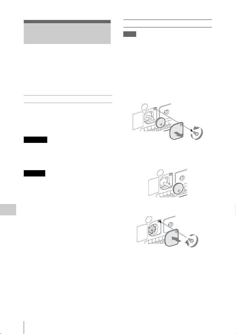
Backup Battery Replacement
166
Appendices
This camcorder uses a backup battery to retain
various setting data.
A lithium battery (CR2032) for backup is
mounted in the camcorder at the factory.
The backup battery retains the date, time, and
timecode in Free Run mode even when no
operating power is being supplied.
Service life of the backup battery
When the backup battery’s voltage falls, the
backup battery low-voltage warning appears on
the LCD monitor/EVF screen.
If this warning appears, replace the battery as
soon as possible.
• Battery may explode if mistreated. Do not
recharge, disassemble, or dispose of in fire.
• Batteries shall not be exposed to excessive heat
such as sunshine, fire or the like.
Danger of explosion if battery is incorrectly
replaced. Replace only with the same or
equivalent type recommended by the
manufacturer.
When you dispose of the battery, you must obey
the law in the relative area or country.
Replacing the backup battery
Notes
• Be sure to set the power switch to OFF when replacing
the backup battery.
• Be careful not to drop the removed screw into the
camcorder.
1 Remove the screw of the backup battery
holder (page 13), then remove the cover.
Insert a nonmetalic item, such as a
plastic toothpick, to the side of the
battery and lever the battery out of its
compartment.
2 Insert a new backup battery (CR2032)
with the + symbol on the battery facing
outside.
3 Attach the cover in the original position.
Backup Battery
Replacement
WARNING
CAUTION
CR2032
3V
CR2032
3V
CR2032
3V

Troubleshooting
167
Appendices
Troubleshooting
Power
Symptoms Cause Remedy
The camcorder does not
power on when you set
the power switch to ON.
No battery pack is mounted and no
power is supplied to the DC IN
connector.
Mount a battery pack (page 18) or connect to AC
power using the BC-U1 or BC-U2 (page 19).
The battery pack is completely
exhausted.
Replace the battery pack with a fully charged one
(page 18).
The power supply cuts
while operating.
The battery pack becomes exhausted. Replace the battery pack with a fully charged one
(page 18).
The battery pack becomes
exhausted very quickly.
The ambient temperature is very low. This owes to the battery characteristics and is not a
defect.
The battery pack is inadequately
charged.
Recharge the battery pack (page 18).
If the battery pack is soon exhausted even after you
charged it fully, it may comes to the end of its life.
Replace it with a new one.
Recording/Playback
Symptoms Cause Remedy
Recording does not start
when you press the REC
START/STOP button.
The power switch is set to OFF. Set the power switch to ON.
The SxS memory card is write-
protected.
Release the write-protection, or replace the card with
a non-protected SxS memory card.
The SxS memory card is full. Replace the card with one having sufficient space.
The SxS memory card needs
restoration.
Restore the memory card (page 24).
Playback does not start
when you press the PLAY
button.
The power switch is set to OFF. Set the power switch to ON.
The supplied IR Remote
Commander does not
work.
Remote control operation is disabled. Enable remote control operation (page 21).
The battery of the IR Remote
Commander is exhausted.
Replace the battery with a new one.
Audio recording is not
possible.
The AUDIO LEVEL CH-1/CH-2
knobs are set to the minimum level.
Adjust the audio recording levels with the AUDIO
LEVEL CH-1/CH-2 knobs (page 38).
The recorded sound is
distorted.
The audio level is too high. Adjust the audio recording levels with the AUDIO
LEVEL CH-1/CH-2 knobs (page 38), and record
again.
The recorded sound has a
high noise level.
The audio level is too low. Adjust the audio recording levels with the AUDIO
LEVEL CH-1/CH-2 knobs (page 38), and record
again.

Troubleshooting
168
Appendices
Note
Obstructions and electromagnetic interference between the camcorder and wireless LAN access point or terminal device,
or the ambient environment (such as wall materials) could shorten the communication range or prevent connections
altogether. If you experience these problems, check the connection/communication status after moving the camcorder to
a new location, or bringing the camcorder and access point/terminal device closer together.
External Devices
Symptoms Cause Remedy
The equipment connected
to the camcorder via an
i.LINK connection does
not react as expected, for
example, no picture
appears on its screen.
It sometimes takes time for the
connected equipment to recognize
the operation.
Wait for about 15 seconds. If the connected
equipment still does not react, do the following:
• Check the i.LINK cable, for example, by re-
plugging it.
• Turn the power off, and connect the cable again.
• Change the i.LINK cable.
When Making a Wireless LAN Connection
Symptoms Remedy
The terminal device cannot access to the
camcorder.
• Check the connection settings of the terminal device such as the IP address
setting, etc.
• The communication setting between the access point and client may be
invalid.
For details, refer to the operating instructions of the access point.
You cannot log in to the camcorder. Check the user name and password that you set.
The Web menu does not appear. • Check the IP address setting.
• Check that the port number (:8080) is added to the IP address.
The wireless LAN cannot be used. Your wireless LAN module may be unsupported.
For details about supported wireless modules, contact your Sony dealer or a
Sony service representative.
The Internet connection
Symptoms Remedy
The modem is not recognized. Your modem may be unsupported.
For details about supported modems, contact your Sony dealer or a Sony
service representative.
The file uploading fails. The user name and password of the server may not be correct. Input the
correct user name and password.
The file uploading is not available. 3G/4G/LTE signal conditions may be poor.
Move to another location and retry.
Wired LAN connection
Symptoms Remedy
“E03-007 IP Address Setting Error”
appears.
There is a conflict in the network addresses of the Wireless LAN and IP
Address settings.
Change the address manually or change the settings for the network router.

Error/Warning Indications
169
Appendices
The camcorder informs you of situations where warning, caution, or an operation check is required,
through messages on the LCD monitor/EVF screen, the tally lamps, and a buzzer.
The buzzer is output to the built-in speaker or to the headphones connected via the headphone connector.
The buzzer volume can be set with “Alarm Level” in “Audio Output” (page 116) of the AUDIO SET
menu.
The camcorder stops operation after the following indications.
When one of the following indications is generated, follow the message to clear the problem.
Error/Warning Indications
Error Indications
Error indication on
LCD/EVF
Buzzer Tally
lamps
Cause and measures
E + Error code Continuous Rapidly
flashing
The camcorder may be defective. Recording stops even if
zREC is displayed on the LCD monitor/EVF screen.
Turn off the power and check the connected equipment, cables,
and media. If they are not defective, turn on the power again. If
the error persists, consult Sony service personnel.
(If power cannot be turned off by setting the power switch to
OFF, remove both the battery pack or the DC IN source.)
Warning Indications
Warning indication
on LCD/EVF
Buzzer Ta lly
lamps
Cause and measures
Media Near Full
Media (A) Near Full
2)
Intermittent Flashing Free space on the SxS memory card has become insufficient.
Replace it with another at the earliest opportunity.
When the Simultaneous Recording in 2 slots mode is set,
“Media (A) Near Full
2)
” appears.
Media Full
Media (A) Full
2)
Continuous Rapidly
flashing
No space is left on the SxS memory card. Recording, clip
copying and clip division cannot be performed.
Replace it with another.
When the Simultaneous Recording in 2 slots mode is set,
“Media (A) Full
2)
” appears.
SD Card Full Continuous Rapidly
flashing
No space is left on the SD card. Recording cannot be
performed.
Replace it with another.
Battery Near End Intermittent Flashing The battery power will be exhausted soon.
Charge the battery pack at the earliest opportunity.
Battery End Continuous Rapidly
flashing
The battery pack is exhausted. Recording cannot be
performed.
Stop operation and change the battery pack.
Temperature High Intermittent Flashing The internal temperature has risen above a safe operation
limit.
Suspend operation, turn off the power, and wait until the
temperature falls.
Voltage Low Intermittent Flashing The DC IN voltage has become low (stage 1).
Check the power supply.

Error/Warning Indications
170
Appendices
Insufficient Voltage Continuous Rapidly
flashing
The DC IN voltage is too low (stage 2). Recording cannot be
performed.
Connect other power source.
HDD A
1)
Battery Near
End
Intermittent Flashing The battery power of the connected HDD will be exhausted
soon.
Change the battery at the earliest opportunity.
HDD A
1)
Battery End
Continuous Rapidly
flashing
The battery of the connected HDD is exhausted. Recording
cannot be performed.
Stop operation to change the battery.
Record Only Media(A)
2)
Flashing When using Simultaneous Recording in the 2 slots, data is
recorded in only one memory card. To record in the 2 slots
simultaneously, stop recording temporarily and insert
recordable memory cards into both slots.
Video Light Battery Near
End
Intermittent Flashing The battery power of the video light mounted on the Multi
Interface Shoe will soon run out.
Change the battery at the earliest opportunity.
Battery Error
Please Change Battery
An error was detected with the battery pack.
Replace the battery pack with a normal one.
Backup Battery End
Please Change
The remaining power of the backup battery is insufficient.
Replace the battery with a new one.
Unknown Media(A)
2)
Please Change
A partitioned memory card or one that contains recorded clips
exceeding the number permitted with this camcorder is loaded.
This card cannot be used with this camcorder. Remove it and
load a compatible card.
Media Error
Media(A)
2)
Needs to be
Restored
An error occurred with the memory card. The card requires
restoration.
Remove the card, load it again, and restore it.
Media Error
Cannot Record to
Media(A)
2)
Recording cannot be done, as the memory card is defective.
As playback may be possible, it is recommended to replace it
with another card after copying the clips, as required.
Media Error
Cannot Use Media(A)
2)
Neither recording nor playback can be done, as the memory
card is defective.
It cannot be operated with this camcorder. Replace it with
another card.
Will Switch Slots Soon This is an advanced notice that the camcorder will switch from
the current memory card to the other memory card for
continuous recording.
No Clip There are no clips in the memory card.
Check the selected card.
Cannot Use Media(A)
2)
Unsupported File System
A card of a different file system or an unformatted card was
inserted. It cannot be used with this camcorder.
Replace it with another card or format it with this camcorder.
In This File system
Cannot Use Media(A)
2)
A memory card incompatible with this file system is inserted.
Replace the card from the respective slot, format it with the
camcorder, or change the “F.Sys.” setting.
Same File Already Exists
Change Media(A)
2)
A clip with the same name exists in the memory card to which
you want to copy.
Replace the card from the respective slot with a different card.
Video Format Mismatch The external signal input via the i.LINK connection cannot be
recorded, as the “Format” setting is different from the signal
format of the external input signal.
Change “Format” in “System” of the OTHERS menu to match
it to that of the external signal.
Warning indication
on LCD/EVF
Buzzer Ta lly
lamps
Cause and measures
Error/Warning Indications
171
Appendices
Copy Protected Input
Cannot Record
The external signal input via the i.LINK connection cannot be
recorded, as the stream is copy-protected.
Check the input signal.
Media Error
Playback Halted
An error occurred in reading data from the memory card, and
playback cannot be continued.
If this frequently occurs, change the memory card after
copying the clips, as required.
Media(A)
2)
Error
Recording cannot be done, as an error occurred with the
memory card.
If this frequently occurs, change the memory card.
Media Reached
Rewriting Limit
Change Media (A)
2)
The memory card comes to the end of its service life. Make a
backup copy and replace the card with another one as soon as
possible. Recording/playback may not be performed properly
if you continue to use the card.
For details, refer to the operating instructions of the memory
card.
Reached Clip Number
Limit
Copy Completed to xx/xx
The maximum number of clips for 1 memory card is reached,
so copying cannot continue. (xx/xx indicates the completed
copy operations.)
Replace the card.
Not Enough Capacity
Copy Completed to xx/xx
There is not enough capacity for copying. (xx/xx indicates the
completed copy operations.)
Replace the card.
Reached Duplication
Limit
Copy Completed to xx/xx
There are already 10 or more clips with the same name as the
clip that you want to copy, so copying cannot continue. (xx/xx
indicates the completed copy operations.)
Replace the card.
Copy Error!
(CANCEL:Abort)
No Media!
There is no memory card inserted in the slot.
Insert a card.
Copy Error!
(CANCEL:Abort)
Media Write Protected
The memory card is write-protected.
Remove the card from the slot and remove the write-
protection.
Copy Error!
(CANCEL:Abort)
Cannot Use Media(A)
2)
A memory card that cannot be used with the camcorder is
inserted.
Replace the card in the respective slot.
Copy General Files
NG: Cannot Copy
Copying of a general file failed.
Retry copying.
Different Media is
Inserted
Cannot Use Media(A)
2)
A different type of card is inserted.
Change the card to the same type as the one inserted before.
Unsupported File System A memory card with an different file system is inserted.
Replace the card, format it with the camcorder, or change the
“F.Sys.” setting.
Cannot Record to SD
Card
NG: Media Write
Protected
The SD card is write-protected.
Remove the card from the slot and remove the write-
protection.
Cannot Record to SD
Card
Reached Clip Number
Limit
The maximum number of clips for 1 SD card is reached, so
copying cannot continue.
Replace the card.
Warning indication
on LCD/EVF
Buzzer Ta lly
lamps
Cause and measures

Error/Warning Indications
172
Appendices
1)B for a HDD connected to slot B
2)(B) for the card in slot B
Cannot Record Proxy
NG: Preparing
The proxy recording function is being prepared. Wait a while.
Power supply to MI Shoe
disabled
If you mount an accessory that requires power supply on the
Multi Interface Shoe while “NW&Proxy/USB” is set to
“Network&Proxy,” no power is supplied.
Cannot Record Proxy When streaming is started, proxy recording to “SD Card” is
not available.
Recording stops when recording is in progress. To start proxy
recording, stop streaming.
When the network client mode is enabled by setting “NCM
with Proxy” to “Disable,” proxy recording is not available.
Proxy Recording will be
stopped
When the network client mode is enabled by setting “NCM
with Proxy” to “Disable” during proxy recording, proxy
recording stops.
Unsupported Device An unsupported device is attached to the external device
connector. Turn the power off to change the device.
Cannot Start Streaming
Invalid Dest. Address
The input address in [Dest.Address] of the streaming settings
may not be correct. Input the correct user address.
Invalid Number A port number that cannot be used in [Dest.Port] of the
streaming settings may be input. Input the correct port number.
Cannot Connect to CCM Although network client mode is activated, the camcorder
cannot be connected to CCM as the camcorder is not
connected to the network. Confirm the network connection
settings.
Cannot Connect to CCM
Invalid User Name or
Password
User name or password for connecting to CCM with the
network client mode may not be correct. Check the settings.
Cannot Connect to CCM
Invalid Address or Port
Number
The address of CCM for the connected equipment with the
network client mode may be not correct or a port number that
cannot be used may be input. Input the correct value.
Cannot Connect to CCM
Certificate is not yet valid
The CCM certificate is not valid. The date setting may be set
to an invalid value. Check the date setting.
Warning indication
on LCD/EVF
Buzzer Ta lly
lamps
Cause and measures

Licenses
173
Appendices
THIS PRODUCT IS LICENSED UNDER THE
AVC PATENT PORTFOLIO LICENSE FOR
THE PERSONAL AND NON-COMMERCIAL
USE OF A CONSUMER TO
(i) ENCODE VIDEO IN COMPLIANCE WITH
THE AVC STANDARD ( “AVC VIDEO”)
AND/OR
(ii) DECODE AVC VIDEO THAT WAS
ENCODED BY A CONSUMER ENGAGED IN
A PERSONAL AND NON-COMMERCIAL
ACTIVITY AND/OR WAS OBTAINED FROM
A VIDEO PROVIDER LICENSED TO
PROVIDE AVC VIDEO.
NO LICENSE IS GRANTED OR SHALL BE
IMPLIED FOR ANY OTHER USE.
ADDITIONAL INFORMATION MAY BE
OBTAINED FROM MPEG LA, L.L.C.
SEE <HTTP://WWW.MPEGLA.COM>
This product uses RICOH Bitmap Fonts
produced and sold by Ricoh Company, Ltd.
IMPORTANT:
BEFORE USING THE SOFTWARE
CONTAINED IN THE CAMCORDER,
PLEASE READ THIS END USER LICENSE
AGREEMENT (“EULA”) CAREFULLY. BY
USING THE SOFTWARE YOU ARE
ACCEPTING THE TERMS OF THIS EULA. IF
YOU DO NOT ACCEPT THE TERMS OF THIS
EULA, YOU MAY NOT USE THE
SOFTWARE.
This EULA is a legal agreement between you and
Sony Corporation (“SONY”). This EULA
governs your rights and obligations regarding the
software of SONY and/or its third party licensors
(including SONY’s affiliates) and their respective
affiliates (collectively, the “THIRD-PARTY
SUPPLIERS”) contained in the camcorder,
together with any updates/upgrades provided by
SONY, any printed, on-line or other electronic
documentation for such software, and any data
files created by operation of such software
(collectively, the “SOFTWARE”).
Notwithstanding the foregoing, any software in
the SOFTWARE having a separate end user
license agreement (including, but not limited to,
GNU General Public license and Lesser/Library
General Public License) shall be covered by such
applicable separate end user license agreement in
lieu of the terms of this EULA to the extent
required by such separate end user license
agreement (“EXCLUDED SOFTWARE”).
SOFTWARE LICENSE
The SOFTWARE is licensed, not sold. The
SOFTWARE is protected by copyright and other
intellectual property laws and international
treaties.
COPYRIGHT
All right and title in and to the SOFTWARE
(including, but not limited to, any images,
photographs, animation, video, audio, music, text
and “applets” incorporated into the SOFTWARE)
is owned by SONY or one or more of the THIRD-
PARTY SUPPLIERS.
GRANT OF LICENSE
SONY grants you a limited license to use the
SOFTWARE solely in connection with the
camcorder and only for your individual use.
SONY and the THIRD-PARTY SUPPLIERS
expressly reserve all rights, title and interest
(including, but not limited to, all intellectual
property rights) in and to the SOFTWARE that
this EULA does not specifically grant to you.
REQUIREMENTS AND LIMITATIONS
You may not copy, publish, adapt, redistribute,
attempt to derive source code, modify, reverse
engineer, decompile, or disassemble any of the
SOFTWARE, whether in whole or in part, or
create any derivative works from or of the
SOFTWARE unless such derivative works are
intentionally facilitated by the SOFTWARE. You
may not modify or tamper with any digital rights
management functionality of the SOFTWARE.
You may not bypass, modify, defeat or
circumvent any of the functions or protections of
the SOFTWARE or any mechanisms operatively
linked to the SOFTWARE. You may not separate
Licenses
MPEG-4 AVC Patent Portfolio
License
Bitmap Fonts
END USER LICENSE AGREEMENT

Licenses
174
Appendices
any individual component of the SOFTWARE
for use on more than one camcorder unless
expressly authorized to do so by SONY. You may
not remove, alter, cover or deface any trademarks
or notices on the SOFTWARE. You may not
share, distribute, rent, lease, sublicense, assign,
transfer or sell the SOFTWARE. The software,
network services or other products other than
SOFTWARE upon which the SOFTWARE’S
performance depends might be interrupted or
discontinued at the discretion of the suppliers
(software suppliers, service suppliers, or SONY).
SONY and such suppliers do not warrant that the
SOFTWARE, network services, contents or other
products will continue to be available, or will
operate without interruption or modification.
EXCLUDED SOFTWARE AND OPEN SOURCE
COMPONENTS
Notwithstanding the foregoing limited license
grant, you acknowledge that the SOFTWARE
may include EXCLUDED SOFTWARE. Certain
EXCLUDED SOFTWARE may be covered by
open source software licenses (“Open Source
Components”), which means any software
licenses approved as open source licenses by the
Open Source Initiative or any substantially
similar licenses, including but not limited to any
license that, as a condition of distribution of the
software licensed under such license, requires
that the distributor make the software available in
source code format. If and to the extent disclosure
is required, please visit www.sony.com/linux or
other SONY-designated web site for a list of
applicable OPEN SOURCE COMPONENTS
included in the SOFTWARE from time to time,
and the applicable terms and conditions
governing its use. Such terms and conditions may
be changed by the applicable third party at any
time without liability to you. To the extent
required by the licenses covering EXCLUDED
SOFTWARE, the terms of such licenses will
apply in lieu of the terms of this EULA. To the
extent the terms of the licenses applicable to
EXCLUDED SOFTWARE prohibit any of the
restrictions in this EULA with respect to such
EXCLUDED SOFTWARE, such restrictions will
not apply to such EXCLUDED SOFTWARE. To
the extent the terms of the licenses applicable to
Open Source Components require SONY to make
an offer to provide source code in connection with
the SOFTWARE, such offer is hereby made.
USE OF SOFTWARE WITH COPYRIGHTED
MATERIALS
The SOFTWARE may be capable of being used
by you to view, store, process and/or use content
created by you and/or third parties. Such content
may be protected by copyright, other intellectual
property laws, and/or agreements. You agree to
use the SOFTWARE only in compliance with all
such laws and agreements that apply to such
content. You acknowledge and agree that SONY
may take appropriate measures to protect the
copyright of content stored, processed or used by
the SOFTWARE. Such measures include, but are
not limited to, counting the frequency of your
backup and restoration through certain
SOFTWARE features, refusal to accept your
request to enable restoration of data, and
termination of this EULA in the event of your
illegitimate use of the SOFTWARE.
CONTENT SERVICE
PLEASE ALSO NOTE THAT THE
SOFTWARE MAY BE DESIGNED TO BE
USED WITH CONTENT AVAILABLE
THROUGH ONE OR MORE CONTENT
SERVICES (“CONTENT SERVICE”). USE OF
THE SERVICE AND THAT CONTENT IS
SUBJECT TO THE TERMS OF SERVICE OF
THAT CONTENT SERVICE. IF YOU
DECLINE TO ACCEPT THOSE TERMS,
YOUR USE OF THE SOFTWARE WILL BE
LIMITED. You acknowledge and agree that
certain content and services available through the
SOFTWARE may be provided by third parties
over which SONY has no control. USE OF THE
CONTENT SERVICE REQUIRES AN
INTERNET CONNECTION. THE CONTENT
SERVICE MAY BE DISCONTINUED AT ANY
TIME.
INTERNET CONNECTIVITY AND THIRD PARTY
SERVICES
You acknowledge and agree that access to certain
SOFTWARE features may require an Internet
connection for which you are solely responsible.
Further, you are solely responsible for payment of
any third party fees associated with your Internet
connection, including but not limited to Internet
service provider or airtime charges. Operation of
the SOFTWARE may be limited or restricted
depending on the capabilities, bandwidth or
technical limitations of your Internet connection
and service. The provision, quality and security of
such Internet connectivity are the sole

Licenses
175
Appendices
responsibility of the third party providing such
service.
EXPORT AND OTHER REGULATIONS
You agree to comply with all applicable export
and re-export restrictions and regulations of the
area or country in which you reside, and not to
transfer, or authorize the transfer, of the
SOFTWARE to a prohibited country or otherwise
in violation of any such restrictions or
regulations.
HIGH RISK ACTIVITIES
The SOFTWARE is not fault-tolerant and is not
designed, manufactured or intended for use or
resale as on-line control equipment in hazardous
environments requiring fail-safe performance,
such as in the operation of nuclear facilities,
aircraft navigation or communication systems, air
traffic control, direct life support machines, or
weapons systems, in which the failure of the
SOFTWARE could lead to death, personal injury,
or severe physical or environmental damage
(“HIGH RISK ACTIVITIES”). SONY, each of
the THIRD-PARTY SUPPLIERS, and each of
their respective affiliates specifically disclaim
any express or implied warranty, duty or
condition of fitness for HIGH RISK
ACTIVITIES.
EXCLUSION OF WARRANTY ON SOFTWARE
You acknowledge and agree that use of the
SOFTWARE is at your sole risk and that you are
responsible for use of the SOFTWARE. The
SOFTWARE is provided “AS IS,” without
warranty, duty or condition of any kind.
SONY AND EACH OF THE THIRD-PARTY
SUPPLIERS (for purposes of this Section, SONY
and each of the THIRD-PARTY SUPPLIERS
shall be collectively referred to as “SONY”)
EXPRESSLY DISCLAIM ALL
WARRANTIES, DUTIES OR CONDITIONS,
EXPRESS OR IMPLIED, INCLUDING, BUT
NOT LIMITED TO, THE IMPLIED
WARRANTIES OF MERCHANTABILITY,
NONINFRINGEMENT AND FITNESS FOR A
PARTICULAR PURPOSE. SONY DOES NOT
WARRANT OR MAKE ANY CONDITIONS
OR REPRESENTATIONS (A) THAT THE
FUNCTIONS CONTAINED IN ANY OF THE
SOFTWARE WILL MEET YOUR
REQUIREMENTS OR THAT THEY WILL BE
UPDATED, (B) THAT THE OPERATION OF
ANY OF THE SOFTWARE WILL BE
CORRECT OR ERROR-FREE OR THAT ANY
DEFECTS WILL BE CORRECTED, (C) THAT
THE SOFTWARE WILL NOT DAMAGE ANY
OTHER SOFTWARE, HARDWARE OR
DATA, (D) THAT ANY SOFTWARE,
NETWORK SERVICES (INCLUDING THE
INTERNET) OR PRODUCTS (OTHER THAN
THE SOFTWARE) UPON WHICH THE
SOFTWARE’S PERFORMANCE DEPENDS
WILL CONTINUE TO BE AVAILABLE,
UNINTERRUPTED OR UNMODIFIED, AND
(E) REGARDING THE USE OR THE
RESULTS OF THE USE OF THE SOFTWARE
IN TERMS OF ITS CORRECTNESS,
ACCURACY, RELIABILITY, OR
OTHERWISE.
NO ORAL OR WRITTEN INFORMATION OR
ADVICE GIVEN BY SONY OR AN
AUTHORIZED REPRESENTATIVE OF SONY
SHALL CREATE A WARRANTY, DUTY OR
CONDITION OR IN ANY WAY INCREASE
THE SCOPE OF THIS WARRANTY. SHOULD
THE SOFTWARE PROVE DEFECTIVE YOU
ASSUME THE ENTIRE COST OF ALL
NECESSARY SERVICING, REPAIR OR
CORRECTION. SOME JURISDICTIONS DO
NOT ALLOW THE EXCLUSION OF IMPLIED
WARRANTIES, SO THESE EXCLUSIONS
MAY NOT APPLY TO YOU.
LIMITATION OF LIABILITY
SONY AND EACH OF THE THIRD-PARTY
SUPPLIERS (for purposes of this Section, SONY
and each of the THIRD-PARTY SUPPLIERS
shall be collectively referred to as “SONY”)
SHALL NOT BE LIABLE FOR ANY
INCIDENTAL OR CONSEQUENTIAL
DAMAGES FOR BREACH OF ANY EXPRESS
OR IMPLIED WARRANTY, BREACH OF
CONTRACT, NEGLIGENCE, STRICT
LIABILITY OR UNDER ANY OTHER LEGAL
THEORY RELATED TO THE SOFTWARE,
INCLUDING, BUT NOT LIMITED TO, ANY
DAMAGES ARISING OUT OF LOSS OF
PROFITS, LOSS OF REVENUE, LOSS OF
DATA, LOSS OF USE OF THE SOFTWARE
OR ANY ASSOCIATED HARDWARE, DOWN
TIME AND USER’S TIME, EVEN IF ANY OF
THEM HAVE BEEN ADVISED OF THE
POSSIBILITY OF SUCH DAMAGES. IN ANY
CASE, EACH AND ALL OF THEIR

Licenses
176
Appendices
AGGREGATE LIABILITY UNDER ANY
PROVISION OF THIS EULA SHALL BE
LIMITED TO THE AMOUNT ACTUALLY
PAID FOR THE PRODUCT. SOME
JURISDICTIONS DO NOT ALLOW THE
EXCLUSION OR LIMITATION OF
INCIDENTAL OR CONSEQUENTIAL
DAMAGES, SO THE ABOVE EXCLUSION
OR LIMITATION MAY NOT APPLY TO
YOU.
CONSENT TO USE OF NON-PERSONAL
INFORMATION, LOCATION DATA, DATA
SECURITY
You acknowledge and agree that SONY and its
affiliates, partners and agents may read, collect,
transfer, process and store certain information
collected from the SOFTWARE, including but
not limited to information about (i) the
SOFTWARE and (ii) the software applications,
contents and peripheral devices that interact with
your camcorder and the SOFTWARE
(“Information”). Information includes, but is not
limited to: (1) unique identifiers relating to your
camcorder and its components; (2) performance
of the camcorder, the SOFTWARE and their
components; (3) configurations of your
camcorder, the SOFTWARE and the software
applications, contents and peripheral devices that
interact with the camcorder and the
SOFTWARE; (4) use and frequency of use of the
functions of (x) the SOFTWARE, and (y) the
software applications, contents and peripheral
devices that interact with the SOFTWARE; and
(5) location data, as indicated below. SONY and
its affiliates, partners and agents may use and
disclose Information subject to applicable laws in
order to improve its products and services or to
provide products or services to you. Such uses
include, but are not limited to: (a) administering
the functionalities of the SOFTWARE; (b) to
improve, service, update or upgrade the
SOFTWARE; (c) improving, developing and
enhancing the current and future products and
services of SONY and other parties; (d) to
provide you with information about the products
and services offered by SONY and other parties;
(e) complying with applicable laws or
regulations; and (f) to the extent offered,
providing you with location-based services of
SONY and other parties, as indicated below. In
addition, SONY retains the right to use
Information to protect itself and third parties from
illegal, criminal or harmful conduct.
Certain services available through the
SOFTWARE may rely upon location
information, including, but not limited to, the
geographic location of the camcorder. You
acknowledge that for the purpose of providing
such services, SONY, the THIRD-PARTY
SUPPLIERS or their partners may collect,
archive, process and use such location data, and
that such services are governed by the privacy
policies of SONY or such third party. By using
any such services, you agree that you have
reviewed the privacy policies applicable to such
services and consent to such activities.
SONY, its affiliates, partners and agents will not
intentionally use Information to personally
identify the owner or user of the SOFTWARE
without your knowledge or consent. Any use of
Information will be in accordance with the
privacy policies of SONY or such third party.
Please contact applicable contact address of each
area or country for SONY’s current privacy
policy.
Please contact applicable third parties for privacy
policies relating to personally identifiable and
other information you provide when you use or
access third party software or services.
Information may be processed, stored or
transferred to SONY, its affiliates or agents which
are located in countries outside of your country of
residence. Data protection and information
privacy laws in certain countries may not offer the
same level of protection as your country of
residence and you may have fewer legal rights in
relation to Information processed and stored in, or
transferred to, such countries. SONY will use
reasonable efforts to take appropriate technical
and organizational steps to prevent unauthorized
access to or disclosure of Information, but does
not warrant it will eliminate all risk of misuse of
such Information.
AUTOMATIC UPDATE FEATURE
From time to time, SONY or the THIRD-PARTY
SUPPLIERS may automatically update or
otherwise modify the SOFTWARE, including,
but not limited to, for purposes of enhancement of
security functions, error correction and

Licenses
177
Appendices
improvement of functions, at such time as you
interact with SONY’s or third parties’ servers, or
otherwise. Such updates or modifications may
delete or change the nature of features or other
aspects of the SOFTWARE, including, but not
limited to, functions you may rely upon. You
acknowledge and agree that such activities may
occur at SONY’s sole discretion and that SONY
may condition continued use of the SOFTWARE
upon your complete installation or acceptance of
such update or modifications. Any updates/
modifications shall be deemed to be, and shall
constitute part of, the SOFTWARE for purposes
of this EULA. By acceptance of this EULA, you
consent to such update/modification.
ENTIRE AGREEMENT, WAIVER, SEVERABILITY
This EULA and SONY’s privacy policy, each as
amended and modified from time to time,
together constitute the entire agreement between
you and SONY with respect to the SOFTWARE.
The failure of SONY to exercise or enforce any
right or provision of this EULA shall not
constitute a waiver of such right or provision. If
any part of this EULA is held invalid, illegal, or
unenforceable, that provision shall be enforced to
the maximum extent permissible so as to maintain
the intent of this EULA, and the other parts will
remain in full force and effect.
GOVERNING LAW AND JURISDICTION
The United Nations Convention on Contracts for
the International Sale of Goods shall not apply to
this EULA. This EULA shall be governed by the
laws of Japan, without regards to conflict of laws
provisions. Any dispute arising out of this EULA
shall be subject to the exclusive venue of the
Tokyo District Court in Japan, and the parties
hereby consent to the venue and jurisdiction of
such courts.
EQUITABLE REMEDIES
Notwithstanding anything contained in this
EULA to the contrary, you acknowledge and
agree that any violation of or non-compliance
with this EULA by you will cause irreparable
harm to SONY, for which monetary damages
would be inadequate, and you consent to SONY
obtaining any injunctive or equitable relief that
SONY deems necessary or appropriate in such
circumstances. SONY may also take any legal
and technical remedies to prevent violation of
and/or to enforce this EULA, including, but not
limited to, immediate termination of your use of
the SOFTWARE, if SONY believes in its sole
discretion that you are violating or intend to
violate this EULA. These remedies are in addition
to any other remedies SONY may have at law, in
equity or under contract.
TERMINATION
Without prejudice to any of its other rights,
SONY may terminate this EULA if you fail to
comply with any of its terms. In case of such
termination, you must: (i) cease all use, and
destroy any copies, of the SOFTWARE; (ii)
comply with the requirements in the section
below entitled “Your Account Responsibilities”.
AMENDMENT
SONY RESERVES THE RIGHT TO AMEND
ANY OF THE TERMS OF THIS EULA AT ITS
SOLE DISCRETION BY POSTING NOTICE
ON A SONY DESIGNATED WEB SITE, BY
EMAIL NOTIFICATION TO AN EMAIL
ADDRESS PROVIDED BY YOU, BY
PROVIDING NOTICE AS PART OF THE
PROCESS IN WHICH YOU OBTAIN
UPGRADES/UPDATES OR BY ANY OTHER
LEGALLY RECOGNIZABLE FORM OF
NOTICE. If you do not agree to the amendment,
you should promptly contact SONY for
instructions. Your continued use of the
SOFTWARE after the effective date of any such
notice shall be deemed your agreement to be
bound by such amendment.
THIRD-PARTY BENEFICIARIES
Each THIRD-PARTY SUPPLIER is an express
intended third-party beneficiary of, and shall have
the right to enforce, each provision of this EULA
with respect to the SOFTWARE of such party.
Should you have any questions concerning this
EULA, you may contact SONY by writing to
SONY at applicable contact address of each area
or country.
Copyright © 2012 Sony Corporation.
This product uses the following software,
released under MIT License.
jQuery JavaScript Library v1.7.2
About JQuery, Sizzle.js and
Jansson

Licenses
178
Appendices
http://jquery.com/
Copyright 2011, John Resig
Sizzle.js
http://sizzlejs.com/
Copyright 2011, The Dojo Foundation
Date: Wed Mar 21 12:46:34 2012 -0700
Jansson 2.6
http://www.digip.org/jansson/
Copyright 2009-2013, Petri Lehtinen
MIT License
Permission is hereby granted, free of charge, to
any person obtaining a copy of this software and
associated documentation files (the “Software”),
to deal in the Software without restriction,
including without limitation the rights to use,
copy, modify, merge, publish, distribute,
sublicense, and/or sell copies of the Software, and
to permit persons to whom the Software is
furnished to do so, subject to the following
conditions:
The above copyright notice and this permission
notice shall be included in all copies or substantial
portions of the Software.
THE SOFTWARE IS PROVIDED "AS IS",
WITHOUT WARRANTY OF ANY KIND,
EXPRESS OR IMPLIED, INCLUDING BUT
NOT LIMITED TO THE WARRANTIES OF
MERCHANTABILITY, FITNESS FOR A
PARTICULAR PURPOSE AND
NONINFRINGEMENT. IN NO EVENT SHALL
THE AUTHORS OR COPYRIGHT HOLDERS
BE LIABLE FOR ANY CLAIM, DAMAGES
OR OTHER LIABILITY, WHETHER IN AN
ACTION OF CONTRACT, TORT OR
OTHERWISE, ARISING FROM, OUT OF OR
IN CONNECTION WITH THE SOFTWARE
OR THE USE OR OTHER DEALINGS IN THE
SOFTWARE.
Because it uses the OpenSSL Toolkit, this
product uses software developed by the OpenSSL
Project (http://www.openssl.org/).
OpenSSL License
---------------
/*
============================
=======
* Copyright (c) 1998-2008 The OpenSSL
* Project. All rights reserved.
*
* Redistribution and use in source and
* binary forms, with or without
* modification, are permitted provided
* that the following conditions are met:
*
* 1. Redistributions of source code must
* retain the above copyright notice,
* this list of conditions and the
* following disclaimer.
*
* 2. Redistributions in binary form must
* reproduce the above copyright
* notice, this list of conditions and the
* following disclaimer in the
* documentation and/or other
* materials provided with the
* distribution.
*
* 3. All advertising materials mentioning
* features or use of this software must
* display the following
* acknowledgment:
* "This product includes software
* developed by the OpenSSL Project
* for use in the OpenSSL Toolkit.
* (http://www.openssl.org/)"
*
* 4. The names "OpenSSL Toolkit" and
* "OpenSSL Project" must not be used
* to endorse or promote products
* derived from this software without
* prior written permission. For written
* permission, please contact openssl-
* core@openssl.org.
*
* 5. Products derived from this software
* may not be called "OpenSSL" nor
* may "OpenSSL" appear in their
* names without prior written
* permission of the OpenSSL Project.
*
* 6. Redistributions of any form
* whatsoever must retain the following
* acknowledgment:
About OpenSSL

Licenses
179
Appendices
* "This product includes software
* developed by the OpenSSL Project
* for use in the OpenSSL Toolkit
* (http://www.openssl.org/)"
*
* THIS SOFTWARE IS PROVIDED BY
* THE OpenSSL PROJECT ``AS IS''
* AND ANY EXPRESSED OR IMPLIED
* WARRANTIES, INCLUDING, BUT NOT
* LIMITED TO, THE IMPLIED
* WARRANTIES OF MERCHANTABILITY
* AND FITNESS FOR A PARTICULAR
* PURPOSE ARE DISCLAIMED. IN NO
* EVENT SHALL THE OpenSSL
* PROJECT OR ITS CONTRIBUTORS BE
* LIABLE FOR ANY DIRECT, INDIRECT,
* INCIDENTAL, SPECIAL, EXEMPLARY,
* OR CONSEQUENTIAL DAMAGES
* (INCLUDING, BUT NOT LIMITED TO,
* PROCUREMENT OF SUBSTITUTE
* GOODS OR SERVICES;
* LOSS OF USE, DATA, OR PROFITS;
* OR BUSINESS INTERRUPTION)
* HOWEVER CAUSED AND ON ANY
* THEORY OF LIABILITY, WHETHER IN
* CONTRACT, STRICT LIABILITY, OR
* TORT (INCLUDING NEGLIGENCE OR
* OTHERWISE)
* ARISING IN ANY WAY OUT OF THE
* USE OF THIS SOFTWARE, EVEN IF
* ADVISED OF THE POSSIBILITY OF
* SUCH DAMAGE.
*
============================
=======
*
* This product includes cryptographic
* software written by Eric Young
* (eay@cryptsoft.com). This product
* includes software written by Tim
* Hudson (tjh@cryptsoft.com).
*
*/
Original SSLeay License
-----------------------
* Copyright (C) 1995-1998 Eric Young
* (eay@cryptsoft.com)
* All rights reserved.
*
* This package is an SSL
* implementation written by Eric Young
* (eay@cryptsoft.com).
* The implementation was written so as
* to conform with Netscapes SSL.
*
* This library is free for commercial and
* non-commercial use as long as the
* following conditions are aheared to.
* The following conditions apply to all
* code found in this distribution, be it the
* RC4, RSA, lhash, DES, etc., code; not
* just the SSL code. The SSL
* documentation included with this
* distribution is covered by the same
* copyright terms except that the holder
* is Tim Hudson (tjh@cryptsoft.com).
*
* Copyright remains Eric Young's, and
* as such any Copyright notices in the
* code are not to be removed.
* If this package is used in a product,
* Eric Young should be given attribution
* as the author of the parts of the library
*used.
* This can be in the form of a textual
* message at program startup or in
* documentation (online or textual)
* provided with the package.
*
* Redistribution and use in source and
* binary forms, with or without
* modification, are permitted provided
* that the following conditions are met:
* 1. Redistributions of source code must
* retain the copyright notice, this list of
* conditions and the following
* disclaimer.
* 2. Redistributions in binary form must
* reproduce the above copyright
* notice, this list of conditions and the
* following disclaimer in the
* documentation and/or other
* materials provided with the
* distribution.
* 3. All advertising materials mentioning
* features or use of this software must
* display the following
* acknowledgement:
* "This product includes
* cryptographic software written by
* Eric Young (eay@cryptsoft.com)"

Specifications
180
Appendices
* The word 'cryptographic' can be left
* out if the rouines from the library
* being used are not cryptographic
* related :-).
* 4. If you include any Windows specific
* code (or a derivative thereof) from
* the apps directory (application
* code) you must include an
* acknowledgement:
* "This product includes software
* written by Tim Hudson
* (tjh@cryptsoft.com)"
*
* THIS SOFTWARE IS PROVIDED BY
* ERIC YOUNG ``AS IS'' AND ANY
* EXPRESS OR IMPLIED WARRANTIES,
* INCLUDING, BUT NOT LIMITED TO,
* THE IMPLIED WARRANTIES OF
* MERCHANTABILITY AND FITNESS
* FOR A PARTICULAR PURPOSE ARE
* DISCLAIMED. IN NO EVENT SHALL
* THE AUTHOR OR CONTRIBUTORS BE
* LIABLE FOR ANY DIRECT, INDIRECT,
* INCIDENTAL, SPECIAL, EXEMPLARY,
* OR CONSEQUENTIAL DAMAGES
* (INCLUDING, BUT NOT LIMITED TO,
* PROCUREMENT OF SUBSTITUTE
* GOODS OR SERVICES; LOSS OF USE,
* DATA, OR PROFITS; OR BUSINESS
* INTERRUPTION)
* HOWEVER CAUSED AND ON ANY
* THEORY OF LIABILITY, WHETHER IN
* CONTRACT, STRICT LIABILITY, OR
* TORT (INCLUDING NEGLIGENCE OR
* OTHERWISE) ARISING IN ANY WAY
* OUT OF THE USE OF THIS SOFTWARE,
* EVEN IF ADVISED OF THE
* POSSIBILITY OF SUCH DAMAGE.
*
* The licence and distribution terms for
* any publically available version or
* derivative of this code cannot be
* changed. i.e. this code cannot simply
* be copied and put under another
* distribution licence [including the GNU
* Public Licence.]
*/
Mass
Approx. 2.4 kg (5 lb 4.7 oz) (Camcorder
only)
Approx. 2.8 kg (6 lb 2.8 oz) (With lens
hood (1), eyecup (1), battery pack BP-
U30 (1), SxS memory card (1))
Dimensions (W × H × D)
168 mm × 161 mm × 331 mm
(6
5
/
8
× 6
3
/
8
× 13
1
/
8
inches)
(Not including extruding parts.)
The values for dimensions are
approximate.
Power Requirements
DC 12 V (11 V to 17 V)
Power Consumption
Approx. 18 W
(while recording with LCD Off, EVF
On, I/O Select Off, and Network
function Off)
Approx. 23 W
(while recording with LCD On, EVF
On, I/O Select HD-SDI, and Network
function On)
Inrush current
(1) Maximum possible inrush current at
initial switch-on (Voltage changes
caused by manual switching): 50 A
peak, 9.5 A r.m.s. (240V AC)
(2) Inrush current after a mains
interruption of five seconds (Voltage
changes caused at zero-crossing): 3 A
peak, 0.7 A r.m.s. (240V AC)
Operating Temperature
0°C to 40°C (32°F to 104°F)
Storage Temperature
–20°C to +60°C (–4°F to +140°F)
Specifications
General

Specifications
181
Appendices
Battery Operation Time
(While recording with LCD Off, EVF
On, I/O Select Off, and Network
function Off)
With battery pack BP-U90: approx. 4.5
hours
With battery pack BP-U60/BP-U60T:
approx. 3 hours
With battery pack BP-U30: approx. 1.5
hours
Recording Format (Video)
XAVC Intra
XAVC-I mode: CBG, 112 Mbps max,
MPEG-4 H.264/AVC
XAVC Long
XAVC-L 50 mode: VBR, 50 Mbps max,
MPEG-4 H.264/AVC
XAVC-L 35 mode: VBR, 35 Mbps max,
MPEG-4 H.264/AVC
XAVC-L 25 mode: VBR, 25 Mbps max,
MPEG-4 H.264/AVC
MPEG-2 Long GOP
MPEG HD422 mode: CBR, 50 Mbps
max, MPEG-2 422P@HL
MPEG HD420 HQ mode: VBR, 35
Mbps max, MPEG-2 MP@HL
MPEG HD420 SP mode: CBR, 25 Mbps
max, MPEG-2 MP@H-14
MPEG IMX
IMX50 mode: CBR, 50 Mbps, MPEG-2
422P@ML Intra
DVCAM
DVCAM mode: CBR, 25 Mbps,
DVCAM
Proxy
AVC/H.264 Main Profile 4:2:0 Long
GOP
1280 × 720/9 Mbps, 6 Mbps
640 × 360/3 Mbps
480 × 270/1 Mbps, 500 kbps (VBR)
Recording Format (Audio)
exFAT
XAVC-I mode: LPCM 24-bit, 48-kHz,
4 channels
XAVC-L mode: LPCM 24-bit, 48-kHz,
4 channels
MPEG HD422 mode: LPCM 24-bit,
48-kHz, 4 channels
MPEG HD420 HQ mode: LPCM 16-bit,
48-kHz, 4 channels
DVCAM mode: LPCM 16-bit, 48-kHz,
4 channels
UDF
MPEG HD422 mode: LPCM 24-bit,
48-kHz, 4 channels
MPEG HD420 HQ mode: LPCM 16-bit,
48-kHz, 4 channels
IMX50 mode: LPCM 24/16-bit,
48-kHz, 4 channels
DVCAM mode: LPCM 16-bit, 48-kHz,
4 channels
FAT
MPEG HD420 HQ mode: LPCM 16-bit,
48-kHz, 4 channels
MPEG HD420 SP mode: LPCM 16-bit,
48-kHz, 4 channels
DVCAM mode: LPCM 16-bit, 48-kHz,
2 channels
Proxy
AAC-LC, 128 kbps, 2 channels
Recording Frame Rate
exFAT
XAVC-I mode:
1920 × 1080/59.94i, 50i, 29.97P,
23.98P, 25P
1280 × 720/59.94P, 50P
XAVC-L50 mode:
1920 × 1080/59.94P, 50P, 59.94i, 50i,
29.97P, 23.98P, 25P
1280 × 720/59.94P, 50P
XAVC-L35 mode:
1920 × 1080/59.94P, 50P, 59.94i, 50i,
29.97P, 23.98P, 25P
XAVC-L25 mode:
1920 × 1080/59.94i, 50i
MPEG HD422 mode:
1920 × 1080/59.94i, 50i, 29.97P,
23.98P, 25P
1280 × 720/59.94P, 50P, 29.97P,
23.98P, 25P

Specifications
182
Appendices
MPEG HD420 HQ mode:
1920 × 1080/59.94i, 50i, 29.97P,
23.98P, 25P
1440 × 1080/59.94i, 50i, 29.97P,
23.98P, 25P
1280 × 720/59.94P, 50P, 23.98P (2-3
Pull Down)
DVCAM mode:
720 × 480/59.94i, 29.97PsF
720 × 576/50i, 25PsF
UDF
MPEG HD422 mode:
1920 × 1080/59.94i, 50i, 29.97P,
23.98P, 25P
1280 × 720/59.94P, 50P, 29.97P,
23.98P, 25P
MPEG HD420 HQ mode:
1920 × 1080/59.94i, 50i, 29.97P,
23.98P, 25P
1440 × 1080/59.94i, 50i, 29.97P,
23.98P, 25P
1280 × 720/59.94P, 50P, 23.98P (2-3
Pull Down)
MPEG IMX50 mode:
720 × 486/59.94i, 29.97PsF
720 × 576/50i, 25PsF
DVCAM mode:
720 × 480/59.94i, 29.97PsF
720 × 576/50i, 25PsF
FAT
MPEG HD420 HQ mode:
1920 × 1080/59.94i, 50i, 29.97P,
23.98P, 25P
1440 × 1080/59.94i, 50i, 29.97P,
23.98P, 25P
1280 × 720/59.94P, 50P, 29.97P,
23.98P, 25P
MPEG HD420 SP mode:
1440 × 1080/59.94i, 50i, 23.98P (2-3
Pull Down)
DVCAM mode:
720 × 480/59.94i, 29.97PsF
720 × 576/50i, 25PsF
Proxy
When the recording format of this unit is
set to 1920 × 1080: 29.97P, 25P,
23.98P
When the recording format of this unit is
set to 1280 × 720: 59.94P, 50P,
29.97P, 25P, 23.98P
Maximum recording time
The maximum recording time is equivalent to the
duration of a single clip recording that fills the
media.
The recording time may become shorter,
depending on the number of recorded clips.
exFAT
XAVC-I mode
When using SBP-128B (128 GB):
Approx. 120 minutes
When using SBP-64B / SBS-64G1A
(64 GB): Approx. 60 minutes
When using SBS-32G1A (32 GB):
Approx. 30 minutes
XAVC-L50 mode
When using SBP-128B (128 GB):
Approx. 240 minutes
When using SBP-64B / SBS-64G1A
(64 GB): Approx. 120 minutes
When using SBS-32G1A (32 GB):
Approx. 60 minutes
XAVC-L35 mode
When using SBP-128B (128 GB):
Approx. 340 minutes
When using SBP-64B / SBS-64G1A
(64 GB): Approx. 170 minutes
When using SBS-32G1A (32 GB):
Approx. 85 minutes
XAVC-L25 mode
When using SBP-128B (128 GB):
Approx. 440 minutes
When using SBP-64B / SBS-64G1A
(64 GB): Approx. 220 minutes
When using SBS-32G1A (32 GB):
Approx. 110 minutes
MPEG HD422 mode
When using SBP-128B (128 GB):
Approx. 240 minutes
When using SBP-64B / SBS-64G1A
(64 GB): Approx. 120 minutes
When using SBS-32G1A (32 GB):
Approx. 60 minutes
MPEG HD420 HQ mode

Specifications
183
Appendices
When using SBP-128B (128 GB):
Approx. 360 minutes
When using SBP-64B / SBS-64G1A
(64 GB): Approx. 180 minutes
When using SBS-32G1A (32 GB):
Approx. 90 minutes
DVCAM mode
When using SBP-128B (128 GB):
Approx. 440 minutes
When using SBP-64B / SBS-64G1A
(64 GB): Approx. 220 minutes
When using SBS-32G1A (32 GB):
Approx. 110 minutes
UDF
MPEG HD422 mode
When using SBP-128B (128 GB):
Approx. 240 minutes
When using SBP-64B / SBS-64G1A
(64 GB): Approx. 120 minutes
When using SBS-32G1A (32 GB):
Approx. 60 minutes
MPEG HD420 HQ mode
When using SBP-128B (128 GB):
Approx. 360 minutes
When using SBP-64B / SBS-64G1A
(64 GB): Approx. 180 minutes
When using SBS-32G1A (32 GB):
Approx. 90 minutes
MPEG IMX50 mode
When using SBP-128B (128 GB):
Approx. 240 minutes
When using SBP-64B / SBS-64G1A
(64 GB): Approx. 120 minutes
When using SBS-32G1A (32 GB):
Approx. 60 minutes
DVCAM mode
When using SBP-128B (128 GB):
Approx. 440 minutes
When using SBP-64B / SBS-64G1A
(64 GB): Approx. 220 minutes
When using SBS-32G1A (32 GB):
Approx. 110 minutes
FAT
MPEG HD420 HQ mode
When using SBP-128B (128 GB):
Approx. 400 minutes
When using SBP-64B / SBS-64G1A
(64GB): Approx. 200 minutes
When using SBS-32G1A (32GB):
Approx. 100 minutes
MPEG HD420 SP mode
When using SBP-128B (128 GB):
Approx. 560 minutes
When using SBP-64B / SBS-64G1A
(64GB): Approx. 280 minutes
When using SBS-32G1A (32GB):
Approx. 140 minutes
DVCAM mode
When using SBP-128B (128 GB):
Approx. 520 minutes
When using SBP-64B / SBS-64G1A
(64GB): Approx. 260 minutes
When using SBS-32G1A (32GB):
Approx. 130 minutes
Lens Mount
Fixed type
Zoom Ratio
17× (optical), power/manual switchable
Focal Length
f = 5.6 mm to 95.2 mm
(equivalent to 29.3 mm to 499 mm on a
35 mm lens)
Iris
Auto/manual switchable
F1.9 to F16 and C (close)
Focus
AF/MF/Full MF switchable
800 mm to ∞ (macro OFF)
50 mm to ∞ (macro ON, wide end)
800 mm to ∞ (macro ON, tele end)
Image Stabilizer
ON/OFF possible, shift-lens system
Filter Diameter
M 77 mm, pitch 0.75 mm
Lens

Specifications
184
Appendices
Image Device (Type)
1/2-inch triple chip “Exmor” Full HD
CMOS image sensor
Effective Picture Elements
1920 (H) × 1080 (V)
Optical System
F1.6 prism system
Built-in Optical Filters
CLEAR: Clear
1: 1/8ND
2: 1/64ND
Sensitivity (2000 lx, 89.9% reflectance)
F12 (typical, 1920 × 1080/59.94i mode)
F13 (typical, 1920 × 1080/50i mode)
Minimum Illumination
0.09 lx (typical, 1920 × 1080/59.94i)
0.07 lx (typical, 1920 × 1080/50i)
(F1.9, +18 dB gain, with 64-frame
accumulation, Gamma off, 100%
video level)
0.02 lx (typical, 1920 × 1080/59.94i)
0.02 lx (typical, 1920 × 1080/50i)
(F1.9, +18 dB gain, with 64-frame
accumulation, Gamma on, 50% video
level)
S/N Ratio
58 dB (Y) (typical)
Horizontal Resolution
1,000 TV lines or more (1920 × 1080i
mode)
Shutter Speed
1/32 sec. to 1/2,000 sec.
Slow Shutter (SLS)
2, 3, 4, 5, 6, 7, 8, 16, 32, and 64-frame
accumulation
Slow & Quick Motion Function
XAVC Intra, XAVC Long
1080P: 1 to 30 and 60 fps in NTSC
setting, 1 to 25 and 50 fps in PAL
setting
720P: 1 to 60 fps in NTSC setting, 1 to
50 fps in PAL setting
MPEG HD422
1080P: 1 to 30 fps in NTSC setting, 1 to
25 fps in PAL setting
720P: 1 to 60 fps in NTSC setting, 1 to
50 fps in PAL setting
MPEG HD420 HQ
1080P: 1 to 30 fps
720P: 1 to 60 fps
White Balance
Preset mode (3200K), Memory A mode,
Memory B mode/ATW mode
Gain
–3, 0, 3, 6, 9, 12, 18 dB, AGC
Gamma Curve
Selectable
Audio Input
XLR type 3-pin (2), female, LINE/MIC/
MIC+48V switchable
LINE: +4 dBu
MIC: –70 dBu to –30 dBu
(Reference level 0 dBu = 0.775 Vrms)
Composite Output
AV multi-connector (1), NTSC or PAL
(common with Audio Output)
Video Output
BNC type (1), HD-Y/composite signal,
switchable with GENLOCK IN
connector
1.0 Vp-p, 75 Ω
Audio Output
AV multi-connector (1),
Camera Section
Inputs/Outputs

Specifications
185
Appendices
-10 dBu (Reference level), 47 kΩ
(common with Composite Output)
SDI Output
BNC type (1), switchable with 3G/HD/
SD
SMPTE 292M/259M/424M/425M
standards
i.LINK
IEEE 1394, 4-pin connector (1), HDV
(HDV 1080i) / DV input/output, S400
Timecode Input
BNC type (1), switchable with TC OUT
connector
0.5 V to 18 Vp-p, 10 kΩ
Timecode Output
BNC type (1), switchable with TC IN
connector
1.0 Vp-p, 75 Ω
Genlock Input
BNC type (1), switchable with VIDEO
OUT connector
1.0 Vp-p, 75 Ω
USB
USB device, mini-B (1)
Headphone Output
Stereo minijack (1)
–18 dBu (Reference level output under
16 Ω load)
Speaker Output
Monaural, 250 mW
DC input
DC jack (1)
Lens Remote
8-pin round (1)
HDMI Output
Type A (1)
Option
4-pin (Type A) (1)
Viewfinder
0.45-inch color LCD: 852 (H) × 480 (V),
16:9
Built-in LCD Monitor
3.5-inch color LCD monitor: 960 (H) ×
3 (RGB) × 540 (V), 16:9
Built-in Microphone
Omnidirectional stereo electret
condenser microphone
Type
ExpressCard/34 slot (2)
Lens hood (1)
This is pre-installed to the camcorder.
EVF eyecup (1)
This is pre-installed to the camcorder.
Infrared Remote Commander (1)
USB wireless LAN module IFU-WLM3 (1)
Accessory shoe kit (1)
BP-U30 battery pack (1)
Battery Charger/AC Adaptor: BC-U1 (1)
Power cord (1)
USB cable (1)
AV connecting cable (1)
Shoulder strap (1)
Lithium battery (CR2032 for backup) (1)
This is pre-installed to the camcorder.
Lithium battery (CR2025 for the IR Remote
Commander) (1)
This is pre-installed to the IR Remote
Commander.
Warranty Booklet (1)
“Before Using this Unit” (1)
CD-ROM “Operating instructions” (1)
Monitoring
Built-in Microphone
Media
Supplied Accessories

Specifications
186
Appendices
Software Downloads
When the unit is used with a PC connection,
download any device drivers, plug-ins, and
application software you require from the
following websites.
Sony Professional products website:
U.S.A. http://pro.sony.com
Canada http://www.sonybiz.ca
Latin America http://sonypro-latin.com
Europe http://www.pro.sony.eu/pro
Middle East, Africa
http://sony-psmea.com
Russia http://sony.ru/pro/
Brazil http://sonypro.com.br
Australia http://pro.sony.com.au
New Zealand http://pro.sony.co.nz
Japan http://www.sonybsc.com
Asia Pacific http://pro.sony-asia.com
Korea http://bp.sony.co.kr
China http://pro.sony.com.cn
India http://pro.sony.co.in
Sony Creative Software, software download
page:
http://www.sonycreativesoftware.com/
download/software_for_sony_equipment
Battery pack
BP-U30, BP-U60, BP-U60T, BP-U90
Battery charger/AC adaptor
BC-U1, BC-U2
SxS memory card
SxS PRO Series
SxS-1 Series
SxS memory card USB reader/writer
SBAC-US20
Media Adaptor
QDA-EX1 (for XQD memory cards)
MEAD-SD02 (for SDHC/SDXC cards)
Electret condenser microphone
ECM-VG1, ECM-673, ECM-674,
ECM-678, ECM-MS2, ECM-680S
Battery video light compatible with the Multi
Interface Shoe
HVL-LBPC
Wireless microphone compatible with the Multi
Interface Shoe
UWP-D11/D12
Multi Interface Shoe mount adaptor
SMAD-P3
Network adaptor kit
CBK-NA1
* To attach accessories to the rear accessory shoe,
use the cold shoe kit.
Design and specifications are subject to change
without notice.
Optional Accessories
Notes
• Always make a test recording, and verify that
it was recorded successfully.
SONY WILL NOT BE LIABLE FOR
DAMAGES OF ANY KIND INCLUDING,
BUT NOT LIMITED TO,
COMPENSATION OR REIMBURSEMENT
ON ACCOUNT OF FAILURE OF THIS
UNIT OR ITS RECORDING MEDIA,
EXTERNAL STORAGE SYSTEMS OR
ANY OTHER MEDIA OR STORAGE
SYSTEMS TO RECORD CONTENT OF
ANY TYPE.
• Always verify that the unit is operating
properly before use. SONY WILL NOT BE
LIABLE FOR DAMAGES OF ANY KIND
INCLUDING, BUT NOT LIMITED TO,
COMPENSATION OR REIMBURSEMENT
ON ACCOUNT OF THE LOSS OF
PRESENT OR PROSPECTIVE PROFITS
DUE TO FAILURE OF THIS UNIT,
EITHER DURING THE WARRANTY
PERIOD OR AFTER EXPIRATION OF
THE WARRANTY, OR FOR ANY OTHER
REASON WHATSOEVER.
• SONY WILL NOT BE LIABLE FOR
CLAIMS OF ANY KIND MADE BY
USERS OF THIS UNIT OR MADE BY
THIRD PARTIES.
• SONY WILL NOT BE LIABLE FOR THE
LOSS, REPAIR, OR REPRODUCTION OF
ANY DATA RECORDED ON THE
INTERNAL STORAGE SYSTEM,
RECORDING MEDIA, EXTERNAL
STORAGE SYSTEMS OR ANY OTHER
MEDIA OR STORAGE SYSTEMS.
• SONY WILL NOT BE LIABLE FOR THE
TERMINATION OR DISCONTINUATION
OF ANY SERVICES RELATED TO THIS
UNIT THAT MAY RESULT DUE TO
CIRCUMSTANCES OF ANY KIND.

Specifications
187
Appendices
• “XDCAM” is a trademark of Sony Corporation.
• “XAVC” and are trademarks of Sony
Corporation.
• Microsoft and Windows are trademarks or
registered trademarks of U.S. Microsoft
Corporation in the U.S. and other countries.
• Mac and Mac OS are registered trademarks of
Apple Inc. in the U.S. and other countries.
• iOS is a registered trademark or trademark of
Cisco Systems, Inc. and/or its affiliates in the
United States and certain other countries.
• HDMI, HDMI logo, and High-Definition
Multimedia Interface are registered trademarks
of HDMI Licensing LLC in the United States
and other countries.
• Android, Google Play are trademarks of Google
Inc.
• Wi-Fi, the Wi-Fi logo, Wi-Fi PROTECTED
SET-UP are registered trademarks of the Wi-Fi
Alliance.
• The N Mark is a trademark or registered
trademark of NFC Forum, Inc. in the United
States and in other countries.
All other product names mentioned herein may be
the trademarks or registered trademarks of their
respective companies. Furthermore, ™ and “®”
are not mentioned in each case in this manual.
On trademarks

Index
188
Appendices
Numerics
23.98P Output 118
3G SDI OUT Level A/B 118
A
A/V OUT connector 139
AC Adaptor 18
AC Power 19
Accessory shoe 10
Accessory shoe plate 10
AGC mode 33
All Reset 129
All-Clip thumbnail screen 89
Aperture 51
Area Detection 53
Assign Button 131
Assignable Buttons 40
ATW 31
ATW Mode 114
ATW Speed 113
Audio Input 115
AUDIO LEVEL knobs 38
audio monitoring 38
Audio Output 116
audio recording levels 38
AUDIO SELECT switches 38
AUDIO SET Menu 115
AUDIO Status 98
Auto Black Bal 114
Auto FB Adjust 45, 114
Auto Naming 29
Auto Shutter 34
Auto White Balance 32
Auto-Tracing White balance 31
B
backlight 20
backup battery 166
Battery Alarm 132
Battery Charger 18
Battery INFO 132
Battery Pack 18
Battery/Media Status Screen 99
Black 52
Black Gamma 52
built-in speaker 91
built-in stereo microphones 37
Button/Remote Status Screen 99
C
Camera Data 129
CAMERA SET Menu 108
CAMERA Status Screen 98
Channel 126
Charge Count 99
Clip 29, 90, 134, 139
Clip Cont. Rec 42, 110
Clip Name Disp 136
Clip name 29
Clip Operation menu 91
Clock 20
Clock Set 130
CMOS Image Sensors 147
Color Bars 109
Color Correction 48
Color Detection 53
Copy 52
Copy All 135
Country 133
Cueing up 91
D
DC IN connector 19
DC IN Power 19
delete shot marks 97
Deleting Clips 54
Depth-of-Field bar indication 15
Detail 50
Direct Menu 16
DISP CLIP INFO 93
Display On/Off 120
Down Converter 118
DURATION/TC/U-BIT button 36
E
Electronic Shutter 33
Electronic Viewfinder 20
Entering a character string 103
Error Indications 169
EVF 20, 119
Index

Index
189
Appendices
EX SLS 34
EXPAND (COARSE) 96
EXPAND (FINE) 96
EXPAND CLIP Screen 92, 95
Exposure 34
ExpressCard slot 139
External Input Signals 142
External Monitors 138
External Synchronization 143
Eyepiece focusing knob 9
F
F.Sys. 133
Fan Control 137
Flange focal length 45
Flicker Reduce 36, 109
Flickers 36
Focus 35
FOCUS MAG button 35
Format 26, 133
Format Media 135
Frame Rec 110
Frame Recording 41, 110
FULL AUTO button 28
Full Auto mode 28
Full MF mode 35
G
Gain 33
Gain Setup 108
Gamma 52
Genlock 132
GENLOCK IN connector 143
GPS
GPS 136
GPS module 9
GPS positioning status indication
100
GPS reception state 59
GPS status indication 15
H
Handle Zoom 109
handle ZOOM button 34
HD Detail 50
HD/SD 133
HDMI OUT connector 138
headphone connector 38
Histogram indication 15
Hours Meter 132
I
i.LINK 141
i.LINK connector 139
Image Alignment 45
Image Inversion 114
Input Source Select 117
Interval Rec 110
Interval Recording 40, 110
IP Address 126
IR Remote 13, 132
J
Jog dial 103
K
Knee 52
KP Flag 39
L
Language 130
LCD 20, 119
LCD/VF SET Menu 119
Lens hood 8
LENS REMOTE connector 35
Limitations of Inputs/Outputs 161
Low Key SAT 52
M
Macro mode 36
Marker 33, 120
Match Clip Name 119
Matrix 47
MEAD-SD02 25, 186
Media Adaptor 25
Media Full 24
Media Near Full 24
Memory A mode 31
Memory B mode 31
MENU button 103
Menu Settings 137
MF Assist 109
microphone holder 37
Monitoring audio 38

Index
190
Appendices
Multi Matrix 48
Multi Matrix mode 47
N
Network Client Mode 76
Network Mode 124
Network Remote 125
Network Reset 128
NFC 126
NG Flag 39
Nonlinear Editing 142
NW Client Edit 124
NW Client Mode 124
NW&Proxy/USB 124
O
OK Flag 39
OK Mark 39
OK-Clip thumbnail screen 89
OTHERS Menu 129
Output Signal 153
P
P.Cache Rec 110
Password 128
PAUSE 96, 97
Peaking 35, 119
Picture Cache Recording 42
Picture Profiles 46
Plan.Metadata 57, 136
Planning metadata 56
PLAY/PAUSE button 90
Power Zoom 34
PP Data 53
Preset mode 31
Preventing switching errors 29
Profile Name 47
Proxy 112
Proxy File 125
Proxy Recording 60
R
REC HOLD lever 29
Rec Review 40, 113
REC REVIEW button 29
REC START/STOP button 29
RECENT FILES Status Screen 100
Recording audio signals 37
recording start mark 42, 92
Reference Tone 39
Regenerate Key 126
Reset 53
S
S&Q Motion 44, 111
SD Detail 50
SDHC Cards 25
SDI OUT connector 138
SDI Rec Control 118, 138
SDI/HDMI/i.LINK I/O Select 117
SDI/HDMI/Video Out Super 118
SEL/SET buttons 103
SEL/SET dial 103
Setting Data 54
Setup Menus 101, 105
Shockless White 113
SHOT MARK 39, 92
SHOT MARK Screen 92, 96
shot marks 39, 91, 97
Shutter 108
Simul Rec 112
Skin Tone Detail 51
SLOT SELECT button 89
Slow & Quick Motion 43
SLS/EX SLS 108
SSID & Key(AP) 126
SSID(ST) 126
Station Set 127
Status Screens 98
Steady Shot 36
Streaming 125
Streaming Edit 125
SxS Device Driver Software 139
SxS Memory Cards 22
System 133
T
Tally 132
TC Format 123
TC IN connector 144
TC Out 145
TC OUT connector 145
TC/UB SET Menu 122
THUMBNAIL button 89

Index
191
Appendices
Thumbnail Screens 88, 91
time and date 20
Time Data 36
Time Zone 20, 130
Timecode 36, 122, 143
TLCS 28, 113
Trigger Mode 132, 141
U
USB cable 139
USB Flash Drives 26
USB wireless LAN module 62
User Data 129
USER Menu 105
USER MENU CUSTOMIZE Menu 105
User Name 128
Users Bit 36, 122
UTC 20
V
Version 137
Version Up 137
Video Formats 30
Video Light Set 114
VIDEO OUT connector 138
VIDEO SET Menu 117
Video Status Screen 99
Viewfinder 20
VOLUME buttons 91
W
Warning Indications 169
White 49
WHITE BAL button 32
WHITE BAL switch 31
White Balance 31
White Clip 52
White Switch <B> 113
Wi-Fi
Wi-Fi remote commander 78
Wi-Fi Version 128
Wi-Fi Version Up 128
Wired LAN Set 128
WPS 126
X
XAVC/MPEG2 133
XQD Memory Cards 25
Z
Zebra 33, 120
zebra pattern 33
Zoom 34, 109
Zoom Speed 35, 109
Zoom Transition 110