Quick Start Guide
FOUR PLAY
Quad Voltage Controlled
Ampliers and Mixer Module
forEurorack
V 2.0
3Quick Start Guide2 FOUR PLAY
(EN) Safety Instruction
1. Please read and follow all instructions.
2. Keep the apparatus away from water, except for
outdoor products.
3. Clean only with a dry cloth.
4. Do not block any ventilation openings. Install in
accordance with the manufacturer’s instructions.
5. Do not install near any heat sources such as
radiators, heat registers, stoves or other apparatus
(including ampliers) that produce heat.
6. Use only attachments/accessories specied by
the manufacturer.
7. Use only specied carts, stands,
tripods, brackets, or tables. Use caution to
prevent tip-over when moving the cart/
apparatus combination.
8. Avoid installing in conned spaces like bookcases.
9. Do not place near naked ame sources,
such as lighted candles.
10. Operating temperature range 5° to 45°C
(41° to 113°F).
LEGAL DISCLAIMER
Music Tribe accepts no liability for any loss which may
be suered by any person who relies either wholly or in
part upon any description, photograph, or statement
contained herein. Technical specications, appearances
and other information are subject to change
without notice. All trademarks are the property of their
respective owners. Midas, Klark Teknik, Lab Gruppen, Lake,
Tannoy, Turbosound, TC Electronic, TC Helicon, Behringer,
Bugera, Aston Microphones and Coolaudio are trademarks
or registered trademarks of Music Tribe Global Brands Ltd.
© Music Tribe Global Brands Ltd. 2024 All rights reserved.
LIMITED WARRANTY
For the applicable warranty terms and conditions and
additional information regarding Music Tribe’s Limited
Warranty, please see complete details online at community.
musictribe.com/support.
(ES) Instrucción de seguridad
1. Por favor, lea y siga todas las instrucciones.
2. Mantenga el aparato alejado del agua, excepto para
productos destinados al uso en exteriores.
3. Limpie solo con un paño seco.
4. No bloquee ninguna abertura de ventilación.
Instale de acuerdo con las instrucciones del fabricante.
5. No instale cerca de fuentes de calor como radiadores,
registros de calor, estufas u otros aparatos
(incluyendo amplicadores) que generen calor.
6. Utilice solo accesorios especicados por el fabricante.
7. Use solo carros, soportes, trípodes,
soportes o mesas especicados.
Tenga precaución para evitar el vuelco al
mover la combinación carro/aparato.
8. Evite la instalación en espacios connados
como estanterías.
9. No colocar cerca de fuentes de llama desnuda,
como velas encendidas.
10. Rango de temperatura de funcionamiento de
5° a 45°C (41° a 113° F).
NEGACIÓN LEGAL
Music Tribe no admite ningún tipo de responsabilidad
por cualquier daño o pérdida que pudiera sufrir
cualquier persona por conar total o parcialmente en la
descripciones, fotografías o armaciones contenidas en
este documento. Las especicaciones técnicas, imágenes
y otras informaciones contenidas en este documento
están sujetas a modicaciones sin previo aviso. Todas las
marcas comerciales que aparecen aquí son propiedad de
sus respectivos dueños. Midas, Klark Teknik, Lab Gruppen,
Lake, Tannoy, Turbosound, TC Electronic, TC Helicon,
Behringer, Bugera, Aston Microphones y Coolaudio son
marcas comerciales o marcas registradas de Music Tribe
Global Brands Ltd. © Music Tribe Global Brands Ltd.
2024 Reservados todos los derechos.
GARANTÍA LIMITADA
Si quiere conocer los detalles y condiciones aplicables de la
garantía así como información adicional sobre la Garantía
limitada de Music Tribe, consulte online toda la información
en la web community.musictribe.com/support.
5Quick Start Guide4 FOUR PLAY
(FR) Consignes de sécurité
1. Veuillez lire et suivre toutes les instructions.
2. Gardez l'appareil éloigné de l'eau, sauf pour les
produits destinés à une utilisation en extérieur.
3. Nettoyez uniquement avec un chion sec.
4. Ne bloquez aucune ouverture de ventilation.
Installez conformément aux instructions du fabricant.
5. N'installez pas près de sources de chaleur telles que
radiateurs, grilles de chaleur, cuisinières ou autres appareils
(y compris les amplicateurs) qui produisent de la chaleur.
6. Utilisez uniquement les accessoires spéciés
par le fabricant.
7. Utilisez uniquement des chariots, des
supports, des trépieds, des supports ou des
tables spéciés. Faites attention pour éviter
le renversement lors du déplacement de la
combinaison chariot/appareil.
8. Évitez l'installation dans des espaces connés comme
les bibliothèques.
9. Ne pas placer près de sources de amme nue, telles
que des bougies allumées.
10. Plage de température de fonctionnement de
5° à 45°C (41° à 113°F).
DÉNI LÉGAL
Music Tribe ne peut être tenu pour responsable pour
toute perte pouvant être subie par toute personne
se ant en partie ou en totalité à toute description,
photographie ou armation contenue dans ce document.
Les caractéristiques, l’apparence et d’autres informations
peuvent faire l’objet de modications sans notication.
Toutes les marques appartiennent à leurs propriétaires
respectifs. Midas, Klark Teknik, Lab Gruppen, Lake, Tannoy,
Turbosound, TC Electronic, TC Helicon, Behringer, Bugera,
Aston Microphones et Coolaudio sont des marques ou
marques déposées de Music Tribe Global Brands Ltd.
© Music Tribe Global Brands Ltd. 2024 Tous droits réservés.
GARANTIE LIMITÉE
Pour connaître les termes et conditions de garantie
applicables, ainsi que les informations supplémentaires et
détaillées sur la Garantie Limitée de Music Tribe, consultez
le site Internet community.musictribe.com/support.
(DE) Wichtige Sicherheitshinweise
1. Bitte lesen Sie alle Anweisungen sorgfältig durch und
befolgen Sie diese.
2. Halten Sie das Gerät von Wasser fern, außer für
Produkte, die für den Außeneinsatz vorgesehen sind.
3. Reinigen Sie es nur mit einem trockenen Tuch.
4. Blockieren Sie keine Belüftungsönungen. Installieren
Sie gemäß den Anweisungen des Herstellers.
5. Installieren Sie nicht in der Nähe von Wärmequellen
wie Heizkörpern, Heizregistern, Öfen oder anderen Geräten
(einschließlich Verstärkern), die Wärme erzeugen.
6. Verwenden Sie nur Zubehörteile, die vom Hersteller
angegeben sind.
7. Verwenden Sie nur spezizierte
Wagen, Ständer, Stative, Halterungen oder
Tische. Achten Sie darauf, beim Bewegen
der Wagen-Geräte-Kombination ein
Umkippen zu vermeiden.
8. Vermeiden Sie die Installation in beengten Räumen
wie Bücherregalen.
9. Nicht in der Nähe von oenen Flammenquellen
platzieren, wie brennende Kerzen.
10. Betriebstem-peraturbereich von 5° bis 45°C
(41° bis 113°F).
HAFTUNGSAUSSCHLUSS
Music Tribe übernimmt keine Haftung für Verluste, die
Personen entstanden sind, die sich ganz oder teilweise
auf hier enthaltene Beschreibungen, Fotos oder Aussagen
verlassen haben. Technische Daten, Erscheinungsbild
und andere Informationen können ohne vorherige
Ankündigung geändert werden. Alle Warenzeichen sind
Eigentum der jeweiligen Inhaber. Midas, Klark Teknik,
Lab Gruppen, Lake, Tannoy, Turbosound, TC Electronic,
TC Helicon, Behringer, Bugera, Aston Microphones
und Coolaudio sind Warenzeichen oder eingetragene
Warenzeichen der Music Tribe Global Brands Ltd. © Music
Tribe Global Brands Ltd. 2024 Alle Rechte vorbehalten.
BESCHRÄNKTE GARANTIE
Die geltenden Garantiebedingungen und zusätzliche
Informationen bezüglich der von Music Tribe gewährten
beschränkten Garantie nden Sie online unter community.
musictribe.com/support.
7Quick Start Guide6 FOUR PLAY
(PT) Instruções de Seguranç
Importantes
1. Por favor, leia e siga todas as instruções.
2. Mantenha o aparelho longe da água, exceto para
produtos destinados ao uso externo.
3. Limpe apenas com um pano seco.
4. Não bloqueie nenhuma abertura de ventilação.
Instale de acordo com as instruções do fabricante.
5. Não instale próximo a fontes de calor, como
radiadores, grelhas de calor, fogões ou outros aparelhos
(incluindo amplicadores) que gerem calor.
6. Use apenas acessórios especicados pelo fabricante.
7. Use apenas carrinhos, suportes, tripés,
suportes ou mesas especicados. Tenha
cuidado para evitar tombamentos ao mover
a combinação carrinho/aparelho.
8. Evite instalar em espaços connados, como estantes.
9. Não coloque perto de fontes de chama nua, como
velas acesas.
10. Intervalo de temperatura de operação de
5° a 45°C (41° a 113° F).
LEGAL RENUNCIANTE
O Music Tribe não se responsabiliza por perda alguma
que possa ser sofrida por qualquer pessoa que dependa,
seja de maneira completa ou parcial, de qualquer
descrição, fotograa, ou declaração aqui contidas. Dados
técnicos, aparências e outras informações estão sujeitas
a modicações sem aviso prévio. Todas as marcas são
propriedade de seus respectivos donos. Midas, Klark Teknik,
Lab Gruppen, Lake, Tannoy, Turbosound, TC Electronic,
TC Helicon, Behringer, Bugera, Aston Microphones e
Coolaudio são marcas ou marcas registradas do Music Tribe
Global Brands Ltd. © Music Tribe Global Brands Ltd. 2024
Todos direitos reservados.
GARANTIA LIMITADA
Para obter os termos de garantia aplicáveis e condições e
informações adicionais a respeito da garantia limitada do
Music Tribe, favor vericar detalhes na íntegra através do
website community.musictribe.com/support.
(IT) Istruzioni di sicurezza importanti
1. Per favore, leggere e seguire tutte le istruzioni.
2. Mantenere l'apparecchio lontano dall'acqua,
tranne per i prodotti destinati all'uso all'aperto.
3. Pulire solo con un panno asciutto.
4. Non ostruire alcuna apertura di ventilazione.
Installare in conformità alle istruzioni del produttore.
5. Non installare vicino a fonti di calore come
termosifoni, bocchette di calore, fornelli o altri apparecchi
(compresi gli amplicatori) che producono calore.
6. Utilizzare solo accessori specicati dal produttore.
7. Usare solo carrelli, supporti,
treppiedi, stae o tavoli specicati.
Prestare attenzione per evitare il
ribaltamento durante lo spostamento della
combinazione carrello/apparecchio.
8. Evitare l'installazione in spazi connati come librerie.
9. Non posizionare vicino a fonti di amma nude, come
candele accese.
10. Intervallo di temperatura di funzionamento da
5° a 45°C (41° a 113°F).
DISCLAIMER LEGALE
Music Tribe non si assume alcuna responsabilità per
eventuali danni che possono essere subiti da chiunque si
adi in tutto o in parte a qualsiasi descrizione, fotograa
o dichiarazione contenuta qui. Speciche tecniche, aspetti
e altre informazioni sono soggette a modiche senza
preavviso. Tutti i marchi sono di proprietà dei rispettivi
titolari. Midas, Klark Teknik, Lab Gruppen, Lake, Tannoy,
Turbosound, TC Electronic, TC Helicon, Behringer, Bugera,
Aston Microphones e Coolaudio sono marchi o marchi
registrati di Music Tribe Global Brands Ltd. © Music Tribe
Global Brands Ltd. 2024 Tutti i diritti riservati.
GARANZIA LIMITATA
Per i termini e le condizioni di garanzia applicabili e le
informazioni aggiuntive relative alla garanzia limitata
di Music Tribe, consultare online i dettagli completi su
community.musictribe.com/support.
9Quick Start Guide8 FOUR PLAY
(NL) Belangrijke
veiligheidsvoorschriften
1. Lees alsjeblieft alle instructies en volg deze op.
2. Houd het apparaat uit de buurt van water, behalve
voor producten die bedoeld zijn voor buitengebruik.
3. Reinig alleen met een droge doek.
4. Blokker geen ventilatieopeningen. Installeer volgens
de instructies van de fabrikant.
5. Installeer niet in de buurt van warmtebronnen
zoals radiatoren, warmte registers, fornuizen of andere
apparaten (inclusief versterkers) die warmte produceren.
6. Gebruik alleen accessoires die door de fabrikant
zijn gespeciceerd.
7. Gebruik alleen gespeciceerde
karren, standaards, statieven, beugels of
tafels. Wees voorzichtig om kantelen te
voorkomen bij het verplaatsen van de kar/
apparaatcombinatie.
8. Vermijd installatie in afgesloten ruimtes zoals
boekenkasten.
9. Plaats niet in de buurt van naakte vlambronnen,
zoals brandende kaarsen.
10. Bedrijfstem-peratuurbereik van 5° tot 45°C
(41° tot 113°F).
WETTELIJKE ONTKENNING
Music Tribe aanvaardt geen aansprakelijkheid voor enig
verlies dat kan worden geleden door een persoon die
geheel of gedeeltelijk vertrouwt op enige beschrijving, foto
of verklaring hierin. Technische specicaties, verschijningen
en andere informatie kunnen zonder voorafgaande
kennisgeving worden gewijzigd. Alle handelsmerken zijn
eigendom van hun respectievelijke eigenaren. Midas,
Klark Teknik, Lab Gruppen, Lake, Tannoy, Turbosound,
TC Electronic, TC Helicon, Behringer, Bugera, Aston
Microphones en Coolaudio zijn handelsmerken of
gedeponeerde handelsmerken van Music Tribe Global
Brands Ltd. © Music Tribe Global Brands Ltd. 2024 Alle
rechten voorbehouden.
BEPERKTE GARANTIE
Voor de toepasselijke garantievoorwaarden en aanvullende
informatie met betrekking tot de beperkte garantie van
Music Tribe, zie de volledige details online op community.
musictribe.com/support.
(SE) Viktiga säkerhetsanvisningar
1. Vänligen läs och följ alla instruktioner noggrant.
2. Håll apparaten borta från vatten, förutom
för utomhusprodukter.
3. Rengör endast med en torr trasa.
4. Blockera inte några ventilationsöppningar.
Installera enligt tillverkarens anvisningar.
5. Installera inte nära några värmekällor som element,
värmeregistrar, spisar eller andra apparater
(inklusive förstärkare) som genererar värme.
6. Använd endast tillbehör som anges av tillverkaren.
7. Använd endast specicerade vagnar,
ställ, stativ, fästen eller bord. Var försiktig
för att undvika att vagnen/
apparatkombinationen tippar
när den yttas.
8. Undvik installation i trånga utrymmen som bokhyllor.
9. Placera inte nära öppen låga, såsom tända ljus.
10. Driftstem-peraturområde 5° till 45°C (41° till 113°F).
FRISKRIVNINGSKLAUSUL
Music Tribe tar inget ansvar för någon förlust som kan
drabbas av någon person som helt eller delvis förlitar sig på
någon beskrivning, fotogra eller uttalande som nns här.
Tekniska specikationer, utseenden och annan information
kan ändras utan föregående meddelande. Alla varumärken
tillhör respektive ägare. Midas, Klark Teknik, Lab Gruppen,
Lake, Tannoy, Turbosound, TC Electronic, TC Helicon,
Behringer, Bugera, Aston Microphones och Coolaudio är
varumärken eller registrerade varumärken som tillhör
Music Tribe Global Brands Ltd. © Music Tribe Global Brands
Ltd. 2024 Alla Rättigheter reserverade.
BEGRÄNSAD GARANTI
För tillämpliga garantivillkor och ytterligare information
om Music Tribes begränsade garanti, se fullständig
information online på community.musictribe.com/support.
11Quick Start Guide10 FOUR PLAY
(PL) Ważne informacje o
bezpieczeństwie
1. Proszę przeczytać i ścisłe przestrzegać
wszystkich instrukcji.
2. Trzymaj urządzenie z dala od wody, z wyjątkiem
produktów przeznaczonych do użytku na zewnątrz.
3. Czyść tylko suchą szmatką.
4. Nie blokuj żadnych otworów wentylacyjnych.
Instaluj zgodnie z instrukcjami producenta.
5. Nie instaluj w pobliżu źródeł ciepła, takich jak
grzejniki, rejestratory ciepła, kuchenki lub inne urządzenia
(w tym wzmacniacze), które generują ciepło.
6. Używaj tylko akcesoriów określonych
przez producenta.
7. Używaj tylko określonych wózków,
stojaków, statywów, uchwytów lub stołów.
Uważaj, aby zapobiec przewróceniu się
wózka/aparatu podczas przemieszczania.
8. Unikaj instalacji w ciasnych miejscach, takich jak
regały na książki.
9. Nie umieszczaj w pobliżu źródeł otwartego ognia,
takich jak zapalone świeczki.
10. Zakres temperatury pracy od 5° do 45°C (41° do 113°F).
ZASTRZEŻENIA PRAWNE
Music Tribe nie ponosi odpowiedzialności za jakiekolwiek
straty, które mogą ponieść osoby, które polegają w
całości lub w części na jakimkolwiek opisie, fotograi
lub oświadczeniu zawartym w niniejszym dokumencie.
Specykacje techniczne, wygląd i inne informacje mogą
ulec zmianie bez powiadomienia. Wszystkie znaki
towarowe są własnością ich odpowiednich właścicieli.
Midas, Klark Teknik, Lab Gruppen, Lake, Tannoy,
Turbosound, TC Electronic, TC Helicon, Behringer, Bugera,
Aston Microphones i Coolaudio są znakami towarowymi
lub zastrzeżonymi znakami towarowymi rmy Music Tribe
Global Brands Ltd. © Music Tribe Global Brands Ltd.
2024 Wszystkie prawa zastrzeżone.
OGRANICZONA GWARANCJA
Aby zapoznać się z obowiązującymi warunkami gwarancji
i dodatkowymi informacjami dotyczącymi ograniczonej
gwarancji Music Tribe, zapoznaj się ze wszystkimi
szczegółami w trybie online pod adresem community.
musictribe.com/support.
(JP) 安全指示
1. すべての指示を読んで、従ってください。
2. 屋外の製品を除き、機器を水から遠ざけ
てください。
3. 乾いた布でのみ清掃してください。
4. 通気口を塞がないでください。メーカーの
指示に従ってインストールしてください。
5. 暖房器、ヒートレジスター、ストーブなど
の発熱機器(アンプを含む)の近くには取り付
けないでください。
6. メーカーが指定したアタッチメント/アク
セサリーのみ使用してください。
7. 指定されたカート、スタン
ド、三脚、ブラケット、またはテ
ーブルのみ使用してください。
カート/機器の組み合わせを移動す
る際には、転倒を防ぐよう注意してください。
8. 書棚などの密閉された空間には設置しない
でください。
9. 裸火のような火の元の近くに置かないで
ください。
10.
動作温度範囲は摂氏 5 度から 45 度
(華氏 41 度から 113 度) です。
法的放棄
ここに含まれる記述、写真、意見の全体または
一部に依拠して、いかなる人が損害を生じさせ
た場合にも、Music Tribe は一切の賠償責任を負
いません。技術仕様、外観およびその他の
情報は予告なく変更になる場合があります。
商標はすべて、それぞれの所有者に帰属し
ます。Midas、Klark Teknik、Lab Gruppen、Lake、Tannoy、
Turbosound、TC Electronic、 TC Helicon、Behringer、Bugera、
Aston Microphones および Coolaudio は Music Tribe
Global Brands Ltd. の商標または登録商標です。
© Music Tribe Global Brands Ltd. 2024 無断転用禁止。
限定保証
適用される保証条件と Music Tribe の限定保
証に関する概要については、オンライン上
community.musictribe.com/support にて詳細をご確
認ください。
13Quick Start Guide12 FOUR PLAY
(CN) 安全须知
1. 请阅读, 保存, 遵守所有的说明, 注意所有
的警示。
2. 请勿在靠近水的地方使用本产品。
3. 请用干布清洁本产品。
4. 请只使用厂家指定的附属设备和配件。 不要
堵塞任何通风口。 按照制造商的说明进行安装。
5. 请只使用厂家指定的或随货
销售的手推车, 架子, 三 角架, 支架和
桌子。 若使用手推车来搬运设备, 请
注意安全放置设备, 以 避免手推车和
设备倾倒而受伤。
6. 请勿安装在密闭空间, 如书柜或类似装置。
7. 请勿将本产品安装在热源附近, 如暖气片,
炉子或其它产生热量的设备 (包括功放器)。 产品上
不要放置裸露的火焰源, 如点燃的蜡烛。
8. 如果液体流入或异物落入设备内, 设备遭雨
淋或受潮, 设备不 能正常运作或被摔坏等, 设备
受损需进行维修时, 所有维修均须由 合格的维修
人员进行维修。
法律声明
对于任何因在此说明书提到的全部或部份描
述、 图片或声明而造成的损失, Music Tribe 不负任
何责任。 技术参数和外观若有更改, 恕不另行通
知。 所有的商标均为其各自所有者的财产。 Midas,
Klark Teknik, Lab Gruppen, Lake, Tannoy, Turbosound,
TC Electronic, TC Helicon, Behringer, Bugera, Aston
Microphones 和 Coolaudio 是 Music Tribe Global Brands
Ltd. 公司的商标或注册商标。 © Music Tribe Global
Brands Ltd. 2024 版权所有。
保修条款
有关音乐集团保修的适用条款及其它相关信息,
请登陆 community.musictribe.com/support 网站查看
完整的详细信息。
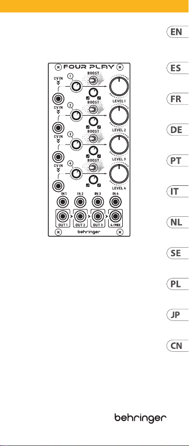
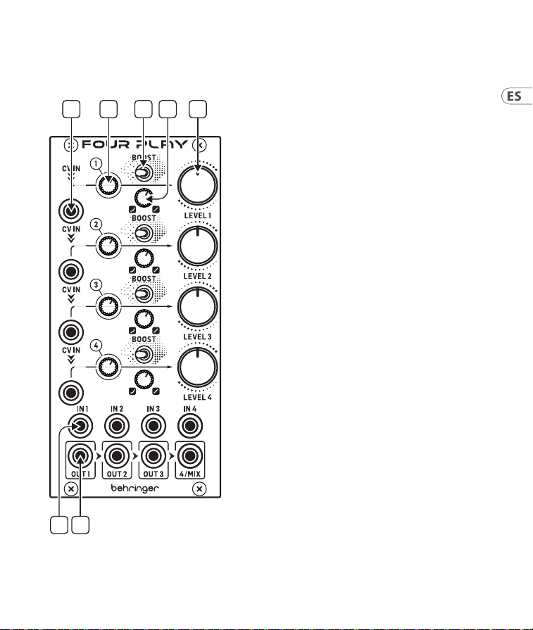
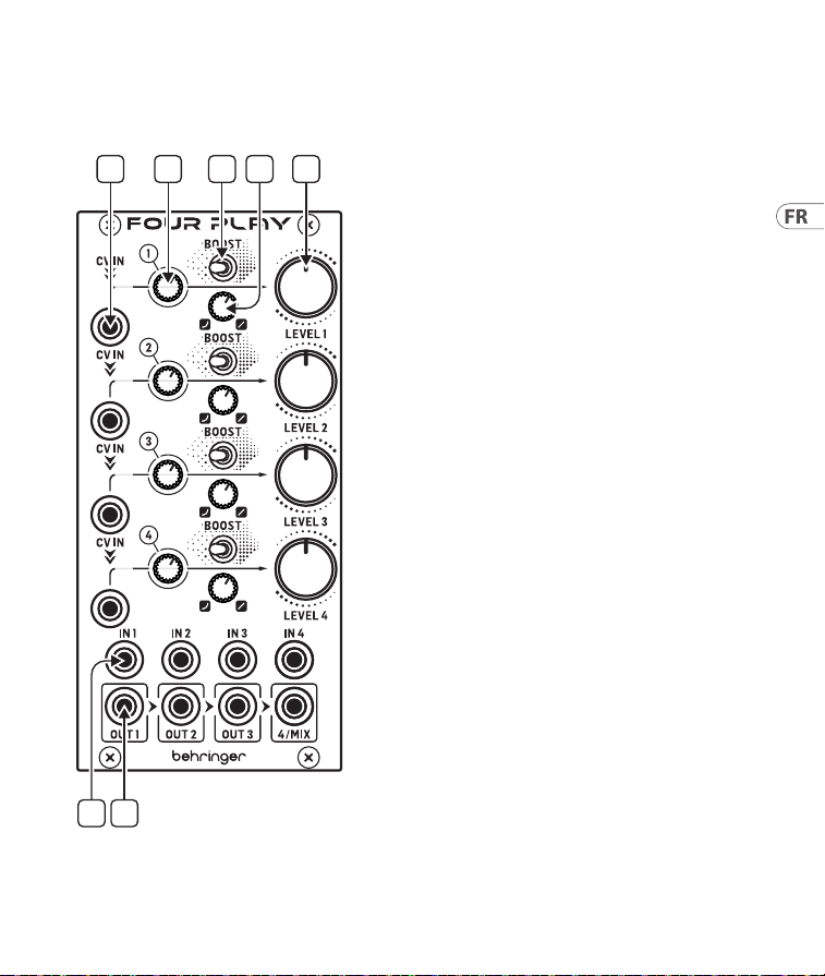
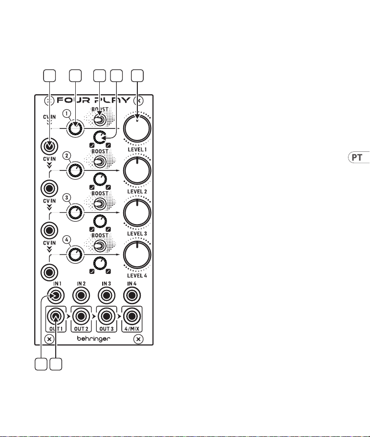
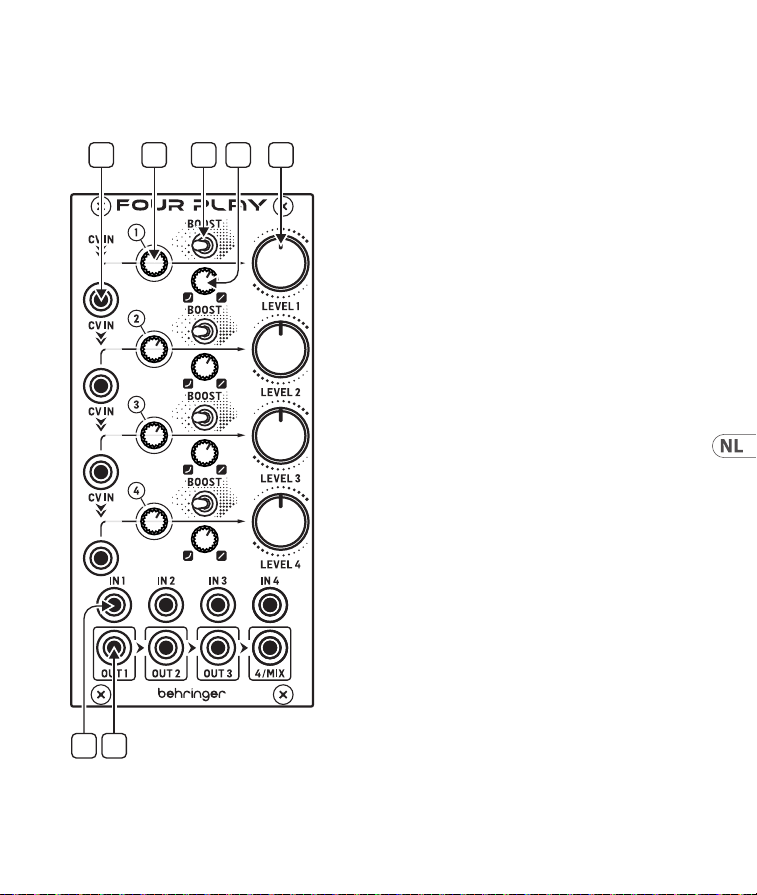
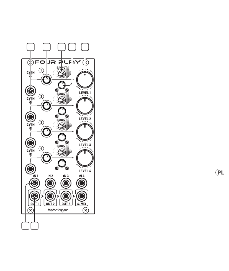
Controls
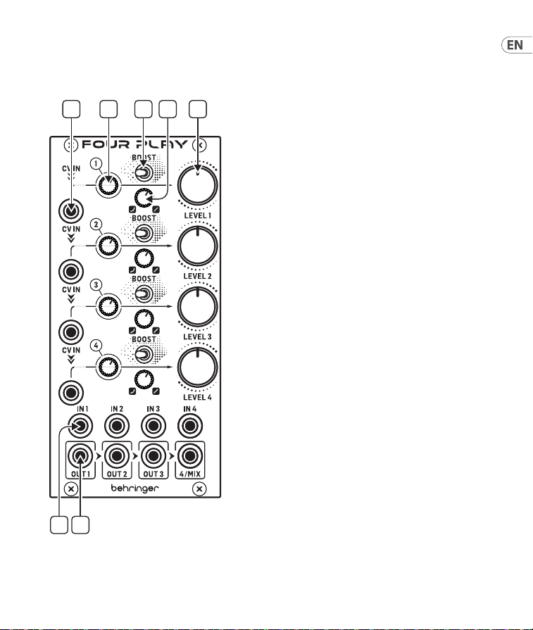
1. CV IN – Each channel has its own CV input
which is cascaded to the channels below,
provided that they do not have a CV cable
inserted. If only CV IN 1 is connected it will
control all 4 channels. Each CV input has an
associated CV LED which lights green for a
positive CV (VCA gain) and red for a negative
CV (VCA attenuation), if the CV IN voltage is
0V then the LED does not light.
2. CV ATTENUATOR – Each channel has a CV
Attenuator, which can reduce the CV input
signal level when moved CCW.
3. BOOST – Each channel has a switchable
Boost control, which raises the input gain by
+6 dB when the switch is set in the right-
hand position.
4. CURVE – Each channel has a continuously
variable VCA response curve, ranging from
exponential at full CCW to linear at full CW.
5. LEVEL – Each channel has its own overall
VCA output level control. The response of
the Level control is aected by the Curve
control setting.
6. INPUTS – Each channel has its own
input, which can be used with audio or CV
input signals.
7. OUTPUTS – Each channel has its own
output, which is mixed with channels to the
right if no output cable is inserted into that
channel output. If only the 4/Mix output
jack is connected the module operates as
a 4 into 1 mixer, which can be operated
manually using the Level controls, or voltage
controlled via the CV inputs.
(EN) Controls
15Quick Start Guide14 FOUR PLAY
1 2 4 5
6 7
3
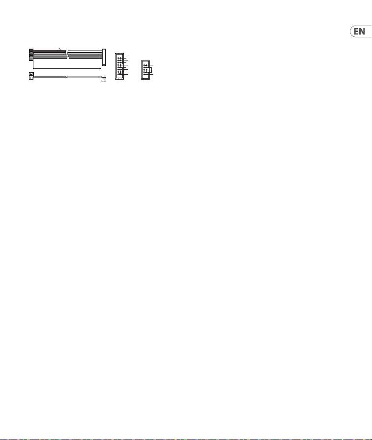
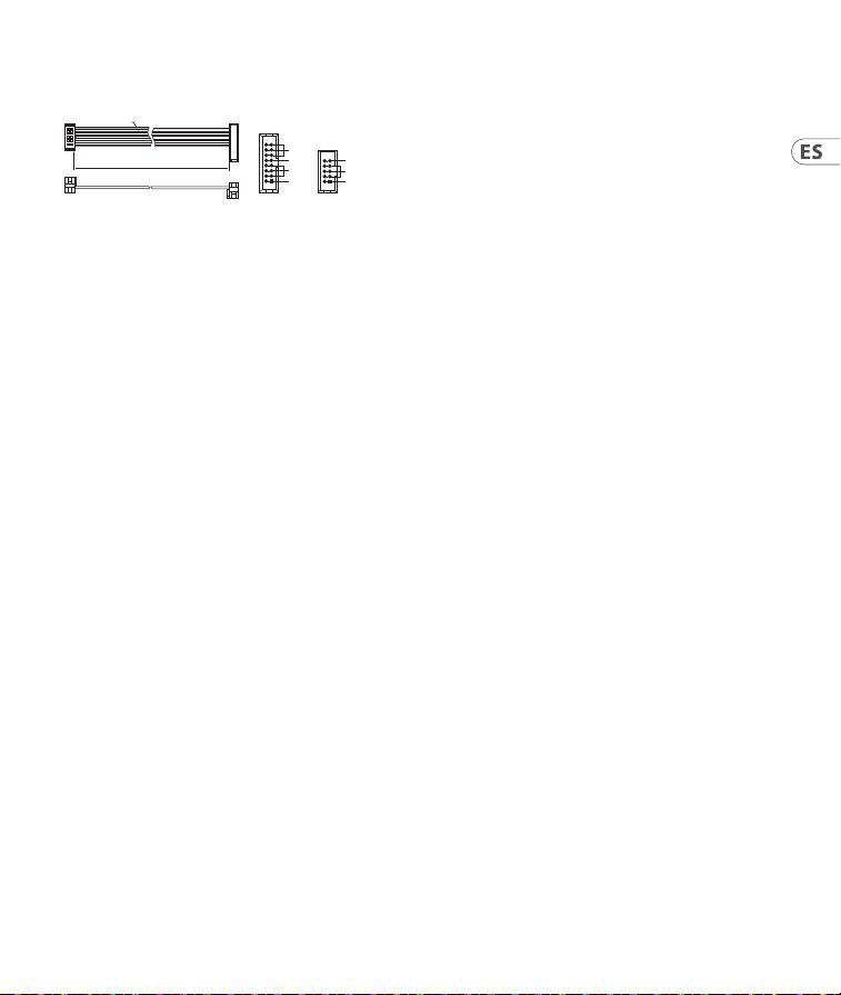
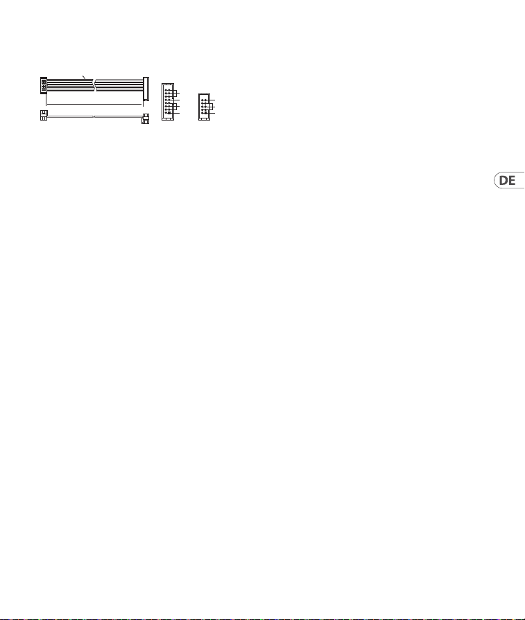
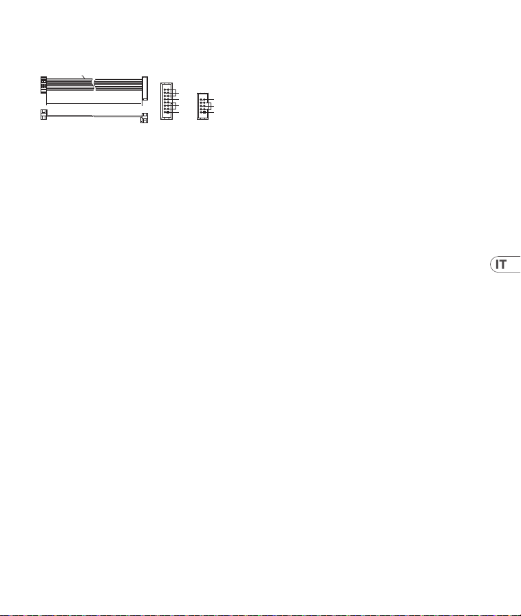
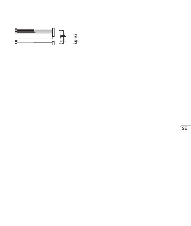
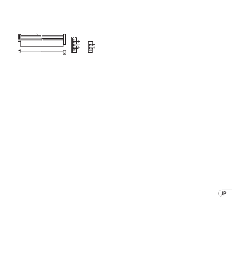
Power Connection
The module comes with the required power cable
for connecting to a standard Eurorack power
supply system. Follow these steps to connect
power to the module. It is easier to make these
connections before the module has been mounted
into a rack case.
1. Turn the power supply or rack case power o
and disconnect the power cable.
2. Insert the 16-pin connector on the power cable
into the socket on the power supply or rack
case. The connector has a tab that will align
with the gap in the socket, so it cannot be
inserted incorrectly. If the power supply does
not have a keyed socket, be sure to orient pin 1
(-12 V) with the red stripe on the cable.
3. Insert the 10-pin connector into the socket on
the back of the module. The connector has a
tab that will align with the socket for correct
orientation.
4. After both ends of the power cable have been
securely attached, you may mount the module
in a case and turn on the power supply.
HOT USED
Red Stripe
200 mm ± 10
15 16
21
P2P1
2
10 9
1
Connect end P1 to the module socket
Connect end P2 to the power supply
+ 12V
- 12V
GROUND
+ 12V
- 12V
GROUND
Installation
The necessary screws are included with the
module for mounting in a Eurorack case.
Connect the power cable before mounting.
Depending on the rack case, there may be a series
of xed holes spaced 2 HP apart along the length
of the case, or a track that allows individual
threaded plates to slide along the length of the
case. The free-moving threaded plates allow
precise positioning of the module, but each plate
should be positioned in the approximate relation
to the mounting holes in your module before
attaching the screws.
Hold the module against the Eurorack rails so
that each of the mounting holes are aligned with
a threaded rail or threaded plate. Attach the
screws part way to start, which will allow small
adjustments to the positioning while you get
them all aligned. After the nal position has been
established, tighten the screws down.
17Quick Start Guide16 FOUR PLAY
19Quick Start Guide18 FOUR PLAY
Controles
(ES) Controles
1. CV IN – Cada canal tiene su propia entrada
CV que está conectada en cascada con
los canales de abajo, suponiendo que no
haya insertado en ellos un cable CV. Si solo
conecta CV IN 1, esa entrada controlará los 4
canales. Cada entrada CV tiene un piloto LED
CV asociado que se ilumina en verde cuando
hay un CV positivo (ganancia VCA) y en rojo
para un CV negativo (atenuación VCA); si el
voltaje de esta entrada CV es 0 V, entonces el
piloto no se iluminará.
2. CV ATTENUATOR – Cada canal tiene un
atenuador de CV, que puede reducir el nivel
de la señal de entrada CV cuando lo gire a
la izquierda.
3. BOOST – Cada canal tiene un control Boost
conmutable, que aumenta la ganancia de
entrada en +6 dB cuando el interruptor esté
colocado en la posición de la derecha.
4. CURVE – Cada canal tiene una curva de
respuesta VCA variable continuamente,
conun rango que va desde exponencial en el
tope izquierdo a lineal en el topederecho.
5. LEVEL – Cada canal tiene su propio control
de nivel de salida VCA global. La respuesta
de este control de nivel se ve afectada por el
ajuste del control de curva.
6. INPUTS – Cada canal tiene su propia
entrada, que puede usar con señales audio o
de entrada CV.
7. OUTPUTS – Cada canal tiene su propia
salida, que es mezclada con los canales
que están a la derecha si no introduce
ningún cable de salida en dicha salida de
canal. Sisolo está conectada la clavija de
salida 4/Mix, el módulo actuará como un
mezclador 4 en 1, que podrá ser controlado
manualmente usando los controles Level,
o controlado por voltaje por medio de las
entradas CV.
1 2 4 5
6 7
3
21Quick Start Guide20 FOUR PLAY
Conexión Eléctrica
El módulo viene con el cable de alimentación
necesario para conectarse a un sistema de
suministro de energía Eurorack estándar.
Siga estos pasos para conectar la alimentación
al módulo. Es más fácil realizar estas conexiones
antes de que el módulo se haya montado en una
caja de rack.
1. Apague la fuente de alimentación o la caja del
bastidor y desconecte el cable de alimentación.
2. Inserte el conector de 16 clavijas del cable
de alimentación en la toma de la fuente
de alimentación o en la caja del bastidor.
El conector tiene una pestaña que se alineará
con el espacio en el zócalo, por lo que no se
puede insertar incorrectamente. Si la fuente
de alimentación no tiene un enchufe con llave,
asegúrese de orientar el pin 1 (-12 V) con la
raya roja en el cable.
3. Inserte el conector de 10 pines en el zócalo en
la parte posterior del módulo. El conector tiene
una pestaña que se alineará con el enchufe
para una orientación correcta.
4. Una vez que ambos extremos del cable de
alimentación se hayan conectado de forma
segura, puede montar el módulo en una caja y
encender la fuente de alimentación.
HOT USED
Red Stripe
200 mm ± 10
15 16
21
P2P1
2
10 9
1
Connect end P1 to the module socket
Connect end P2 to the power supply
+ 12V
- 12V
GROUND
+ 12V
- 12V
GROUND
Instalación
Los tornillos necesarios se incluyen con el módulo
para su montaje en una caja Eurorack. Conecte el
cable de alimentación antes del montaje.
Dependiendo de la caja del bastidor, puede haber
una serie de oricios jos separados 2 HP a lo largo
de la caja, o una pista que permita que las placas
roscadas individuales se deslicen a lo largo de
la caja. Las placas roscadas de movimiento libre
permiten un posicionamiento preciso del módulo,
pero cada placa debe colocarse en una relación
aproximada con los oricios de montaje en su
módulo antes de colocar los tornillos.
Sostenga el módulo contra los rieles Eurorack de
modo que cada uno de los oricios de montaje
esté alineado con un riel o placa roscada. Coloque
los tornillos parcialmente para comenzar, lo
que permitirá pequeños ajustes en la posición
mientras los alinea todos. Una vez establecida la
posición nal, apriete los tornillos.
23Quick Start Guide22 FOUR PLAY
Réglages
(FR) Réglages
1. CV IN – Chaque canal dispose de son entrée
CV et est relié au canal suivant si aucun câble
n’est connecté. Si un câble est connecté
uniquement à l’entrée CV IN 1, il permet de
contrôler les 4 canaux. Chaque entrée CV
dispose d’une LED CV correspondante qui
s’allume en vert pour une tension de contrôle
positive (amplication du VCA) et en rouge
pour une tension de contrôle négative
(atténuation du VCA). Si la tension en entrée
est de 0 V, laLED ne s’allume pas.
2. CV ATTENUATOR – Chaque canal dispose
d’un atténuateur CV permettant de réduire
la tension de contrôle si le potentiomètre
est tourné vers la gauche.
3. BOOST – Chaque canal dispose d’un réglage
Boost commutable permettant d’amplier le
gain d’entrée de +6 dB lorsque le sélecteur
est placé sur la position de droite.
4. CURVE – Chaque canal dispose d’un réglage
de courbe de réponse du VCA, modiable
d’exponentielle si tourné à gauche à linéaire
si tourné à droite.
5. LEVEL – Chaque canal dispose d’un réglage
de niveau de sortie du VCA. La réponse du
réglage Level est aectée par le réglage
de la courbe.
6. INPUTS – Chaque canal dispose d’une
entrée pouvant être utilisée avec un
signal audio ou CV.
7. OUTPUTS – Chaque canal dispose d’une
sortie qui est mélangée avec la sortie des
canaux situés à sa droite si aucun câble
n’y est connecté. Si un câble est connecté
uniquement à la sortie 4/Mix, le module
fonctionne alors comme une console de
mixage 4 canaux vers 1 sortie pouvant être
pilotée avec les réglages de niveau ou avec
des tensions de contrôle dans les entrées CV.
1 2 4 5
6 7
3
25Quick Start Guide24 FOUR PLAY
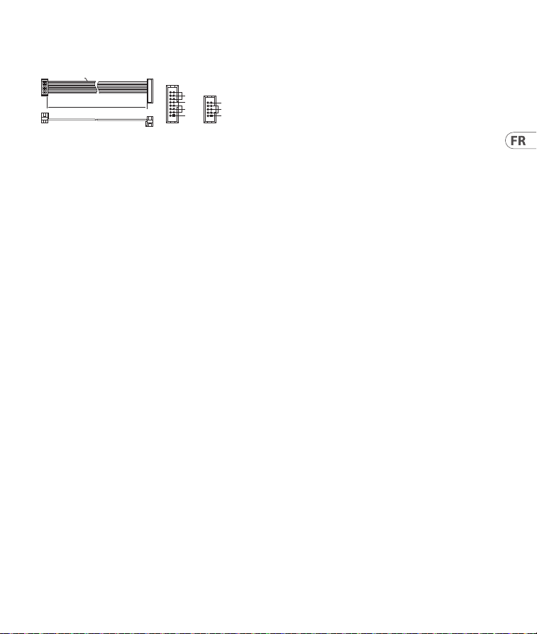
Connexion Électrique
Le module est livré avec le câble d’alimentation
requis pour la connexion à un système
d’alimentation standard Eurorack. Suivez ces
étapes pour connecter l’alimentation au module. Il
est plus facile d’eectuer ces connexions avant que
le module n’ait été monté dans un boîtier de rack.
1. Mettez le bloc d’alimentation ou le boîtier
de rack hors tension et débranchez le câble
d’alimentation.
2. Insérez le connecteur à 16 broches du
câble d’alimentation dans la prise du bloc
d’alimentation ou du boîtier du rack.
Le connecteur a une languette qui s’alignera
avec l’espace dans la prise, de sorte qu’il ne
peut pas être inséré de manière incorrecte.
Si le bloc d’alimentation n’a pas de prise à clé,
veillez à orienter la broche 1 (-12 V) avec la
bande rouge sur le câble.
3. Insérez le connecteur à 10 broches dans la prise
à l’arrière du module. Le connecteur a une
languette qui s’alignera avec la prise pour une
orientation correcte.
4. Une fois que les deux extrémités du câble
d’alimentation ont été solidement xées, vous
pouvez monter le module dans un boîtier et
allumer l’alimentation.
HOT USED
Red Stripe
200 mm ± 10
15 16
21
P2P1
2
10 9
1
Connect end P1 to the module socket
Connect end P2 to the power supply
+ 12V
- 12V
GROUND
+ 12V
- 12V
GROUND
Installation
Les vis nécessaires sont incluses avec le module
pour le montage dans un boîtier Eurorack.
Connectez le câble d’alimentation avant
le montage.
Selon le cas de rack, il peut y avoir une série de
trous xes espacés de 2 HP sur la longueur du
cas, ou une piste qui permet aux plaques letées
individuelles de glisser le long de la longueur
du cas. Les plaques letées à déplacement
libre permettent un positionnement précis du
module, mais chaque plaque doit être positionnée
approximativement par rapport aux trous de
montage de votre module avant de xer les vis.
Maintenez le module contre les rails Eurorack
de sorte que chacun des trous de montage soit
aligné avec un rail leté ou une plaque letée.
Fixez les vis partiellement pour commencer,
ce qui permettra de petits ajustements au
positionnement pendant que vous les alignerez
tous. Une fois la position nale établie, serrez les
vis vers le bas.
27Quick Start Guide26 FOUR PLAY
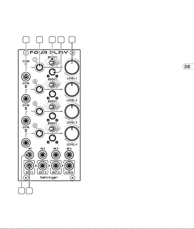
Bedienelemente
(DE) Bedienelemente
1. CV IN – Jeder Kanal verfügt über einen
eigenen CV-Eingang, der zu den darunter
liegenden Kanälen kaskadiert wird, sofern
diese nicht mit einem CV-Kabel belegt
sind. Wenn nur CV IN 1 angeschlossen ist,
steuert er alle 4 Kanäle. Jeder CV-Eingang
hat eine zugehörige CV-LED, die bei einer
positiven CV (VCA-Verstärkung) grün und
bei einer negativen CV (VCA-Bedämpfung)
rot leuchtet. Wenn die CV IN-Spannung 0 V
beträgt, leuchtet die LED nicht.
2. CV ATTENUATOR – Jeder Kanal verfügt über
einen CV-Bedämpfungsregler, der durch eine
Linksdrehung den CV-Eingangssignalpegel
verringern kann.
3. BOOST – Jeder Kanal verfügt über einen
Boost-Schalter, der in der rechten Position
die Eingangsverstärkung um +6 dB anhebt.
4. CURVE – Jeder Kanal verfügt über eine
stufenlos regelbare VCA-Kennlinie, die von
exponentiell bei voller Linksdrehung bis
linear bei voller Rechtsdrehung reicht.
5. LEVEL – Jeder Kanal verfügt über einen
eigenen VCA-Gesamtausgangspegelregler.
Die Ansprache des Pegelreglers
wird von der Einstellung des
Kennlinienreglersbeeinusst.
6. INPUTS – Jeder Kanal verfügt über einen
eigenen Eingang, in den Audio- oder
CV-Signale eingespeist werden können.
7. OUTPUTS – Jeder Kanal verfügt über
einen eigenen Ausgang, der mit den rechts
daneben liegenden Kanälen gemischt
wird, wenn kein Ausgangskabel in diesen
Kanalausgang eingesteckt ist. Wenn nur die
4/Mix-Ausgangsbuchse angeschlossen ist,
funktioniert das Modul als 4-in-1-Mischer,
der manuell mit den Level-Reglern oder
spannungsgesteuert über die CV-Eingänge
bedient werden kann.
1 2 4 5
6 7
3
29Quick Start Guide28 FOUR PLAY
Netzanschluss
Das Modul wird mit dem erforderlichen
Stromkabel für den Anschluss an ein Standard-
Eurorack-Stromversorgungssystem geliefert.
Befolgen Sie diese Schritte, um das Modul
mit Strom zu versorgen. Es ist einfacher, diese
Verbindungen herzustellen, bevor das Modul in
ein Rackgehäuse eingebaut wurde.
1. Schalten Sie das Netzteil oder das Rackgehäuse
aus und ziehen Sie das Netzkabel ab.
2. Stecken Sie den 16-poligen Stecker am
Netzkabel in die Buchse am Netzteil oder im
Rack-Gehäuse. Der Anschluss verfügt über
eine Lasche, die an der Lücke in der Buchse
ausgerichtet ist, sodass sie nicht falsch
eingesetzt werden kann. Wenn das Netzteil
keine Schlüsselbuchse hat, achten Sie darauf,
Pin 1 (-12 V) mit dem roten Streifen am
Kabel auszurichten.
3. Stecken Sie den 10-poligen Stecker in die
Buchse auf der Rückseite des Moduls.
Der Anschluss verfügt über eine Lasche,
die zur korrekten Ausrichtung an der Buchse
ausgerichtet wird.
4. Nachdem beide Enden des Netzkabels fest
angeschlossen wurden, können Sie das
Modul in einem Gehäuse montieren und die
Stromversorgung einschalten.
HOT USED
Red Stripe
200 mm ± 10
15 16
21
P2P1
2
10 9
1
Connect end P1 to the module socket
Connect end P2 to the power supply
+ 12V
- 12V
GROUND
+ 12V
- 12V
GROUND
Installation
Die erforderlichen Schrauben sind im
Lieferumfang des Moduls für die Montage in
einem Eurorack-Gehäuse enthalten. Schließen Sie
das Netzkabel vor der Montage an.
Abhängig vom Rack-Gehäuse kann es eine Reihe
von festen Löchern geben, die entlang der Länge
des Gehäuses 2 PS voneinander entfernt sind, oder
eine Schiene, mit der einzelne Gewindeplatten
entlang der Länge des Gehäuses gleiten können.
Die frei beweglichen Gewindeplatten ermöglichen
eine präzise Positionierung des Moduls.
Jede Platte sollte jedoch in der ungefähren
Beziehung zu den Befestigungslöchern in
Ihrem Modul positioniert werden, bevor Sie die
Schrauben anbringen.
Halten Sie das Modul so gegen die Eurorack-
Schienen, dass jedes der Befestigungslöcher mit
einer Gewindeschiene oder einer Gewindeplatte
ausgerichtet ist. Bringen Sie die Schrauben
teilweise an, um zu beginnen. Dadurch können
Sie die Position geringfügig anpassen, während
Sie alle ausrichten. Ziehen Sie die Schrauben
fest, nachdem die endgültige Position
festgelegt wurde.
31Quick Start Guide30 FOUR PLAY
Controles
(PT) Controles
1. CV IN – Cada canal tem sua própria entrada
CV que é conectada aos canais abaixo, desde
que eles não tenham um cabo CV inserido. Se
apenas o CV IN 1 é conectado, ele controlará
todos os 4 canais. Cada entrada CV tem um
LED CV associado que acende uma luz verde
para CV positivo (ganho de VCA) e vermelha
para CV negativo (atenuação de VCA), se a
tensão CV IN for de 0V o LED não acende.
2. CV ATTENUATOR – Cada canal
temumatenuador de CV que pode reduziro
nível do sinal de entrada CVquando
movimentado no sentido
anti-horário (CCW).
3. BOOST – Cada canal tem um controle de
Boost comutável que aumenta o ganho da
entrada em até +6 dB quando o interruptor
está ajustado na posição do lado direito.
4. CURVE – Cada canal tem uma curva de
resposta VCA continuamente variável, que
varia de exponencial na posição anti-horária
(CCW) máxima, até linear na posição
horária (CW).
5. LEVEL – Cada canal tem seu próprio nível de
saída geral VCA. A resposta do controle de
nível é afetada pela conguração do controle
da curva.
6. INPUTS – Cada canal tem sua própria
entrada que pode ser usada com sinais de
entrada CV de áudio.
7. OUTPUTS – Cada canal tem sua própria
saída que é misturada aos canais à direita se
nenhum cabo de saída for inserido na saída
do canal. Se apenas o jack de saída 4/Mix
estiver conectado, o módulo operará como
um mixer 4 em 1, quepode ser operado
manualmente usando os controles Level, ou
tensão controlada pelas entradas CV.
1 2 4 5
6 7
3
33Quick Start Guide32 FOUR PLAY
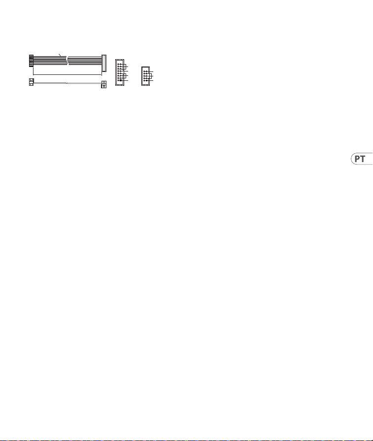
Conexão de Força
O módulo vem com o cabo de alimentação
necessário para conectar a um sistema de fonte de
alimentação Eurorack padrão. Siga estas etapas
para conectar a alimentação ao módulo. É mais
fácil fazer essas conexões antes que o módulo seja
montado em um gabinete de rack.
1. Desligue a fonte de alimentação ou o gabinete
do rack e desconecte o cabo de alimentação.
2. Insira o conector de 16 pinos do cabo
de alimentação no soquete da fonte de
alimentação ou no gabinete do rack. O conector
possui uma aba que se alinhará com a lacuna
no soquete, portanto, não pode ser inserido
incorretamente. Se a fonte de alimentação não
tiver um soquete chaveado, certique-se de
orientar o pino 1 (-12 V) com a faixa vermelha
no cabo.
3. Insira o conector de 10 pinos no soquete na
parte traseira do módulo. O conector possui
uma guia que se alinha ao soquete para
orientação correta.
4. Depois que ambas as extremidades do cabo de
alimentação forem conectadas com segurança,
você pode montar o módulo em uma caixa e
ligar a fonte de alimentação.
HOT USED
Red Stripe
200 mm ± 10
15 16
21
P2P1
2
10 9
1
Connect end P1 to the module socket
Connect end P2 to the power supply
+ 12V
- 12V
GROUND
+ 12V
- 12V
GROUND
Instalação
Os parafusos necessários estão incluídos com
o módulo para montagem em uma caixa
Eurorack. Conecte o cabo de alimentação antes
da montagem.
Dependendo da caixa do rack, pode haver uma
série de orifícios xos espaçados de 2 HP ao
longo do comprimento da caixa, ou um trilho
que permite que placas roscadas individuais
deslizem ao longo do comprimento da caixa.
As placas roscadas de movimento livre permitem
o posicionamento preciso do módulo, mas cada
placa deve ser posicionada em relação aproximada
aos orifícios de montagem em seu módulo antes
de prender os parafusos.
Segure o módulo contra os trilhos Eurorack de
forma que cada um dos orifícios de montagem
quem alinhados com um trilho ou placa
rosqueada. Prenda os parafusos parcialmente
para começar, o que permitirá pequenos ajustes
no posicionamento enquanto você os alinha.
Depois de estabelecida a posição nal, aperte
os parafusos.
35Quick Start Guide34 FOUR PLAY
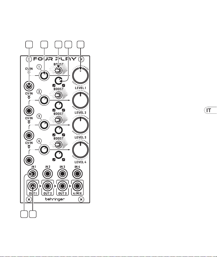
Controlli
(IT) Controlli
1. CV IN – ogni canale ha il suo ingresso CV che
è collegato in cascata ai canali sottostanti,
purché non abbiano un cavo CV inserito. Se
è collegato solo CV IN 1, controllerà tutti e 4
i canali. Ogni ingresso CV è associato al suo
led CV che si illumina in verde per CV positivo
(guadagno VCA) e rosso per CV negativo
(attenuazione VCA), il led non si illumina se
la tensione del relativo CV IN è 0V.
2. CV ATTENUATOR – ogni canale ha un
attenuatore CV, che può ridurre il livello del
segnale di ingresso CV quando è girato in
senso antiorario.
3. BOOST – ogni canale ha un controllo BOOST
commutabile, che aumenta il guadagno in
ingresso di +6dB quando l’interruttore è
nella posizione di destra.
4. CURVE – ogni canale ha una curva di
risposta VCA continuamente variabile
che va da esponenziale, totalmente in
senso antiorario, a lineare, totalmente in
sensoorario.
5. LEVEL – ogni canale ha il suo controllo
del livello di uscita VCA generale. La
risposta del controllo LEVEL è inuenzata
dall’impostazione del controllo CURVE.
6. INPUTS – ogni canale ha il suo ingresso,
che può essere usato con segnali di ingresso
audio o CV.
7. OUTPUTS – ogni canale ha la sua uscita, che
è mixata con i canali a destra se nessun cavo
di uscita è inserito nell’uscita di quel canale.
Se collegate solo il jack di uscita 4/Mix,
il modulo funziona come un mixer 4 su 1,
che può essere controllato manualmente
tramite i controlli di livello o controllato in
tensione tramite gli ingressi CV.
1 2 4 5
6 7
3
37Quick Start Guide36 FOUR PLAY
Connessione di Alimentazione
Il modulo viene fornito con il cavo di alimentazione
necessario per il collegamento a un sistema di
alimentazione Eurorack standard. Seguire questi
passaggi per collegare l’alimentazione al modulo.
È più facile eettuare questi collegamenti prima
che il modulo sia stato montato in un case rack.
1. Spegnere l’alimentatore o il case del rack e
scollegare il cavo di alimentazione.
2. Inserire il connettore a 16 pin del cavo di
alimentazione nella presa sull’alimentatore
o sulla custodia del rack. Il connettore ha una
linguetta che si allineerà con lo spazio nella
presa, quindi non può essere inserito in modo
errato. Se l’alimentatore non dispone di una
presa con chiave, assicurarsi di orientare il pin 1
(-12 V) con la striscia rossa sul cavo.
3. Inserire il connettore a 10 pin nella presa
sul retro del modulo. Il connettore ha una
linguetta che si allineerà con la presa per un
corretto orientamento.
4. Dopo che entrambe le estremità del cavo di
alimentazione sono state ssate saldamente, è
possibile montare il modulo in una custodia e
accendere l’alimentatore.
HOT USED
Red Stripe
200 mm ± 10
15 16
21
P2P1
2
10 9
1
Connect end P1 to the module socket
Connect end P2 to the power supply
+ 12V
- 12V
GROUND
+ 12V
- 12V
GROUND
Installazione
Le viti necessarie sono incluse con il modulo per il
montaggio in una custodia Eurorack. Collegare il
cavo di alimentazione prima del montaggio.
A seconda del case del rack, potrebbero esserci
una serie di fori ssi distanziati di 2 HP l’uno
dall’altro lungo la lunghezza del case, o un binario
che consente alle singole piastre lettate di
scorrere lungo la lunghezza del case. Le piastre
lettate a movimento libero consentono un
posizionamento preciso del modulo, ma ciascuna
piastra deve essere posizionata in relazione
approssimativa con i fori di montaggio nel modulo
prima di ssare le viti.
Tenere il modulo contro le guide Eurorack in modo
che ciascuno dei fori di montaggio sia allineato con
una guida lettata o una piastra lettata. Attacca
le viti in parte per iniziare, il che consentirà piccoli
aggiustamenti al posizionamento mentre le fai
allineare tutte. Dopo aver stabilito la posizione
nale, serrare le viti.
39Quick Start Guide38 FOUR PLAY
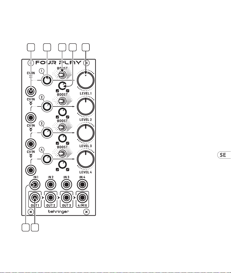
Bediening
(NL) Bediening
1. CV IN – elk kanaal heeft zijn eigen
CV-ingang, die naar de kanalen eronder
wordt gestuurd, mits er geen CV-kabel is
geplaatst. Als er alleen iets op CV IN 1 is
aangesloten, dan zullen alle 4 de kanalen
worden aangestuurd. Elke CV-ingang
heeft een gekoppelde CV-LED, die groen
brandt voor een positieve CV (VCA-gain) en
rood oplicht voor een negatieve CV (VCA-
verzwakking). Als de spanning op CVIN
0 V is, brandt de LED niet.
2. CV ATTENUATOR – elk kanaal
heeft een CV-attenuator die het
CV-ingangssignaalniveau vermindert als de
knop naar links wordt gedraaid.
3. BOOST – elk kanaal heeft een schakelbare
Boost-regelaar die de ingangswaarde met
+6 dB verhoogt als de schakelaar in de
rechter stand wordt gezet.
4. CURVE – elk kanaal heeft een continu
variabele VCA-responscurve, variërend van
exponentieel (helemaal naar links gedraaid)
tot lineair (helemaal naar rechtsgedraaid).
5. LEVEL – elk kanaal heeft een eigen VCA-
totaalvolumeregelaar (level). De respons van
de niveauregelaar wordt beïnvloed door de
instelling van de curveregelaar.
6. INPUTS – elk kanaal heeft een eigen ingang,
die kan worden gebruikt voor audio of
CV-ingangssignalen.
7. OUTPUTS – elk kanaal heeft een eigen
uitgang, die met de kanalen rechts wordt
gemixt als er geen uitvoerkabel in de
betreende kanaal-uitgang is geplaatst.
Als alleen de 4/mixuitgang is aangesloten,
werkt de module als een 4 in 1 mixer,
diehandmatig kan worden bediend met
de niveauregelaar, of als er spanning op de
CV-ingangen staat.
1 2 4 5
6 7
3
41Quick Start Guide40 FOUR PLAY
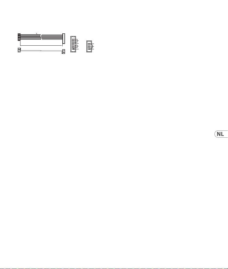
Stroomaansluiting
De module wordt geleverd met de benodigde
voedingskabel voor aansluiting op een standaard
Eurorack-voedingssysteem. Volg deze stappen
om de module van stroom te voorzien. Het is
gemakkelijker om deze aansluitingen te maken
voordat de module in een rekbehuizing
is gemonteerd.
1. Schakel de voeding of de rekbehuizing uit en
koppel de voedingskabel los.
2. Steek de 16-pins connector van de
voedingskabel in de aansluiting op de
voedingseenheid of rekbehuizing.
De connector heeft een lipje dat wordt
uitgelijnd met de opening in de socket,
zodat deze niet verkeerd kan worden
geplaatst. Als de voeding geen contactdoos
met sleutel heeft, zorg er dan voor dat pen 1
(-12 V) met de rode streep op de kabel
wordt georiënteerd.
3. Steek de 10-pins connector in de aansluiting
aan de achterkant van de module.
De connector heeft een lipje dat uitgelijnd is
met de aansluiting voor de juiste oriëntatie.
4. Nadat beide uiteinden van de voedingskabel
stevig zijn bevestigd, kunt u de module in een
hoesje monteren en de voeding inschakelen.
HOT USED
Red Stripe
200 mm ± 10
15 16
21
P2P1
2
10 9
1
Connect end P1 to the module socket
Connect end P2 to the power supply
+ 12V
- 12V
GROUND
+ 12V
- 12V
GROUND
Installatie
De benodigde schroeven worden bij de module
geleverd voor montage in een Eurorack-koer.
Sluit de voedingskabel aan voor montage.
Afhankelijk van de rackbehuizing kan er een
reeks vaste gaten zijn die 2 HP uit elkaar
liggen over de lengte van de behuizing, of
een rail waarmee afzonderlijke platen met
schroefdraad langs de lengte van de behuizing
kunnen schuiven. De vrij bewegende plaatjes
met schroefdraad maken een nauwkeurige
positionering van de module mogelijk, maar
elke plaat moet ongeveer in verhouding tot de
montagegaten in uw module worden geplaatst
voordat u de schroeven bevestigt.
Houd de module tegen de Eurorack-rails zodat elk
van de montagegaten is uitgelijnd met een rail
met schroefdraad of een plaat met schroefdraad.
Bevestig de schroeven halverwege om te
beginnen, waardoor kleine aanpassingen aan de
positionering mogelijk zijn terwijl u ze allemaal
op één lijn krijgt. Nadat de denitieve positie is
bepaald, draait u de schroeven vast.
43Quick Start Guide42 FOUR PLAY
Kontroller
(SE) Kontroller
1. CV IN – Varje kanal har en egen CV-ingång
som är kaskadkopplad till kanalerna
nedanför, om de inte har en CV-kabel
ansluten. Om endast CV IN 1 är ansluten
kommer den att styra samtliga fyra
kanaler. Varje CV-ingång har en tillhörande
CV-lysdiod som lyser grön för en positiv
CV (VCA-gain) och röd för en negativ CV
(VCA-dämpning), om CV IN-spänningen är
0 V lyser inte lysdioden.
2. CV ATTENUATOR – Varje kanal har
en CV-dämpare, som kan reducera
CV-insignalnivån när den föryttas moturs.
3. BOOST – Varje kanal har en växlingsbar
boost-kontroll, som ökar ingångs-gainen
med +6 dB när omkopplaren ställs
ihögerpositionen.
4. CURVE – Varje kanal har en kontinuerligt
variabel VCA-responskurva, som går från
exponentiell vid fullt moturs till linjär vid
fullt medurs.
5. LEVEL – Varje kanal har en egen
allmän VCA-utgångsnivåkontroll.
Nivåkontrollens respons påverkas av
kurvkontrollinställningen.
6. INPUTS – Varje kanal har en egen
ingång, som kan användas med ljud-
eller CV-insignaler.
7. OUTPUTS – Varje kanal har en egen
utgång, som mixas med kanaler till höger
om ingen utgångskabel är ansluten till
den kanalutgången. Om endast 4/Mix-
utgångsuttaget är anslutet fungerar
modulen som en fyra till en-mixer, som kan
hanteras manuellt med Level-kontrollerna,
eller spänningsstyrt via CV-ingångarna.
1 2 4 5
6 7
3
Installation
De nödvändiga skruvarna ingår i modulen
för montering i ett Eurorack-fodral. Anslut
strömkabeln före montering.
Beroende på stativhöljet kan det nnas en serie
fasta hål som är åtskilda 2 hk längs höljets längd
eller ett spår som gör att enskilda gängade plattor
kan glida längs höljets längd. De fritt rörliga
gängade plattorna möjliggör exakt positionering
av modulen, men varje platta bör placeras i
ungefärlig relation till monteringshålen i din
modul innan skruvarna fästs.
Håll modulen mot Eurorack-skenorna så att var
och en av monteringshålen ligger i linje med en
gängad skena eller gängad platta. Fäst skruvarna
delvis för att börja, vilket gör det möjligt att
justera små positioner medan du justerar dem
alla. När den slutliga positionen har fastställts drar
du åt skruvarna.
45Quick Start Guide44 FOUR PLAY
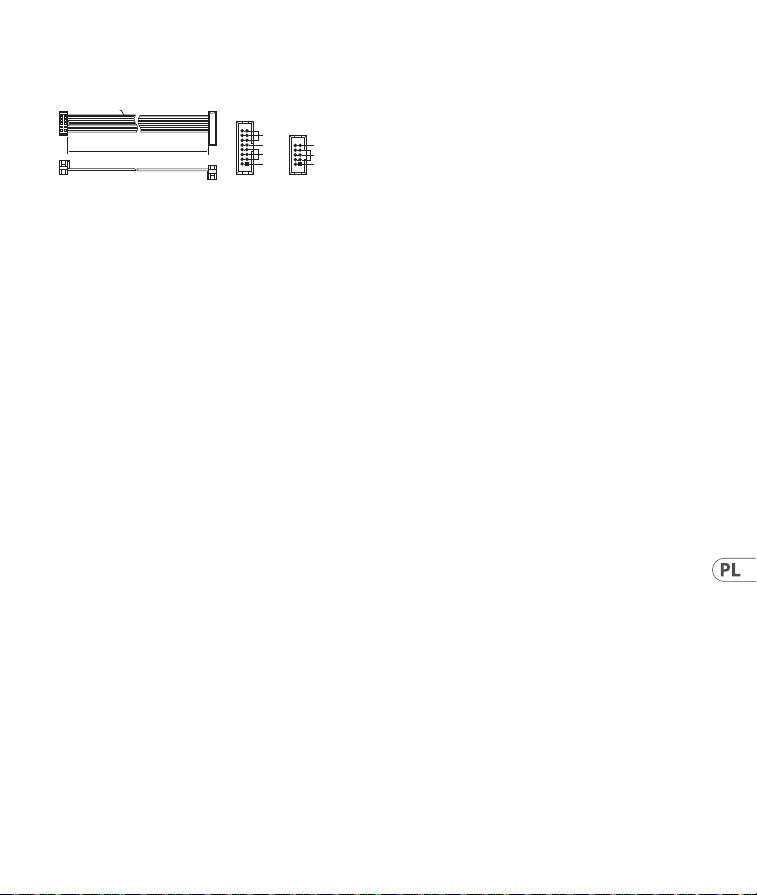
Strömanslutning
Modulen levereras med den strömkabel som
krävs för att ansluta till ett vanligt Eurorack-
nätaggregat. Följ dessa steg för att ansluta
ström till modulen. Det är lättare att göra dessa
anslutningar innan modulen har monterats
i ett rackfodral.
1. Stäng av strömmen eller rackhöljet och koppla
bort strömkabeln.
2. Sätt i den 16-poliga kontakten på strömkabeln
i uttaget på nätaggregatet eller rackfodralet.
Kontaktdonet har en ik som kommer i linje
med springan i uttaget så att den inte kan
sättas in felaktigt. Om strömförsörjningen inte
har ett nyckeluttag, se till att orientera stift 1
(-12 V) med den röda remsan på kabeln.
3. Sätt i 10-polig kontakt i uttaget på
baksidan av modulen. Kontaktdonet har
en ik som kommer i linje med uttaget för
korrekt orientering.
4. När båda ändarna av strömkabeln har anslutits
ordentligt kan du montera modulen i ett fodral
och slå på strömförsörjningen.
HOT USED
Red Stripe
200 mm ± 10
15 16
21
P2P1
2
10 9
1
Connect end P1 to the module socket
Connect end P2 to the power supply
+ 12V
- 12V
GROUND
+ 12V
- 12V
GROUND
47Quick Start Guide46 FOUR PLAY
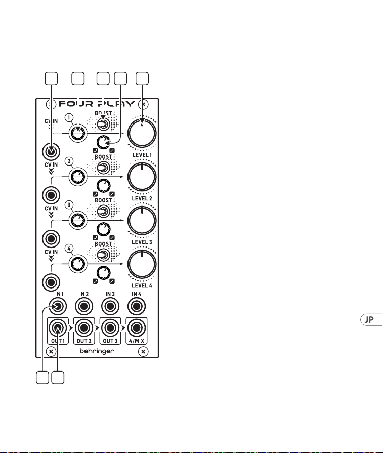
Sterowanica
(PL) Sterowanica
1. CV IN – Każdy z kanałów posiada swoje
wejście CV, które przepływa kaskadowo do
kanałów poniżej, zakładając że nie jest w nie
wpięty kabel CV. Jeśli podłączony jest tylko
CV IN 1, będzie on kontrolował wszystkie 4
kanały. Każde wejście CV posiada powiązaną
diodę CV, która świeci się na zielono dla
dodatniego CV (wzmocnienie VCA) lub na
czerwono dla ujemnego CV (tłumienie VCA).
Jeśli napięcie CV IN wynosi 0V, dioda nie
świeci się.
2. CV ATTENUATOR – Każdy kanał posiada
tłumienie CV, które może zredukować
poziom sygnału wejściowego CV po
przekręceniu w lewo.
3. BOOST – Każdy kanał posiada przełączaną
regulację wzmocnienia, które zwiększa
poziom wejściowy o +6 dB, gdy przełącznik
jest ustawiony w prawo.
4. CURVE – Każdy kanał posiada
ciągle zmienną krzywą reakcji VCA,
odwykładniczej w ustawieniu całkiem w
lewo, do liniowej w ustawieniu całkiem
w prawo.
5. LEVEL – Każdy kanał posiada swoją
regulację ogólnego poziomu wyjściowego
VCA. Działanie regulacji Level jest zależne od
ustawienia Curve.
6. INPUTS – Każdy kanał posiada swoje
własne wejście, które może być używane z
sygnałami wejściowymi audio lub CV.
7. OUTPUTS – Każdy kanał posiada swoje
własne wyjście, które jest miksowane
z kanałami w prawo, jeśli żaden kabel
wyjściowy nie jest podłączony do tego
wyjścia kanału. Jeśli podłączone jest tylko
wyjście 4/Mix, moduł działa jak mikser
4do 1, który może być sterowany ręcznie
za pomocą regulacji Level lub napięciem za
pomocą wejść CV.
1 2 4 5
6 7
3
49Quick Start Guide48 FOUR PLAY
Podłączenie Zasilania
Do modułu dołączony jest wymagany kabel
zasilający do podłączenia do standardowego
systemu zasilania Eurorack. Wykonaj poniższe
czynności, aby podłączyć zasilanie do modułu.
Łatwiej jest wykonać te połączenia przed
zamontowaniem modułu w obudowie rack.
1. Wyłącz zasilacz lub obudowę szafy i odłącz
kabel zasilający.
2. Włóż 16-stykowe złącze przewodu zasilającego
do gniazda w zasilaczu lub w szae typu rack.
Złącze ma wypustkę, która będzie wyrównana
ze szczeliną w gnieździe, więc nie można jej
nieprawidłowo włożyć. Jeśli zasilacz nie ma
gniazda z kluczem, należy zorientować styk 1
(-12 V) z czerwonym paskiem na kablu.
3. Włóż 10-pinowe złącze do gniazda z tyłu
modułu. Złącze ma wypustkę, która będzie
wyrównana z gniazdem, aby zapewnić
prawidłową orientację.
4. Po solidnym zamocowaniu obu końców kabla
zasilającego można zamontować moduł w
obudowie i włączyć zasilacz.
HOT USED
Red Stripe
200 mm ± 10
15 16
21
P2P1
2
10 9
1
Connect end P1 to the module socket
Connect end P2 to the power supply
+ 12V
- 12V
GROUND
+ 12V
- 12V
GROUND
Instalacja
Do modułu dołączone są niezbędne śruby do
montażu w skrzynce Eurorack. Podłącz kabel
zasilający przed montażem.
W zależności od obudowy szafy może występować
szereg stałych otworów rozmieszczonych w
odstępach 2 HP na całej długości obudowy lub
prowadnica, która umożliwia przesuwanie
pojedynczych gwintowanych płyt wzdłuż całej
obudowy. Swobodnie poruszające się gwintowane
płytki umożliwiają precyzyjne ustawienie
modułu, ale każda płyta powinna być ustawiona w
przybliżeniu w stosunku do otworów montażowych
w module przed przykręceniem śrub.
Przytrzymaj moduł na szynach Eurorack, tak aby
każdy z otworów montażowych był wyrównany z
szyną gwintowaną lub płytą gwintowaną. Wkręć
śruby częściowo, aby rozpocząć, co pozwoli na
drobne korekty położenia, gdy wszystkie zostaną
wyrównane. Po ustaleniu ostatecznego położenia
dokręcić śruby.
51Quick Start Guide50 FOUR PLAY
コントロール
(JP) コントロール
1. CV IN – 各チャンネルにはCV 入力が
装備されており、CV ケーブル を 挿入
することなく下 部 の チャンネルに転
送されます。CV IN 1 にのみ 接続した
場合は、4 つの 全 チャンネル を制 御
し ま す 。各 CV 入力は LED を備 えてお
り、CV が正電圧 (VCA ゲイン) の場
合は緑色に、CV が負電圧 (VCA 減衰)
の場合は赤色に点灯、CV IN の電圧が
0 V の場合は LED は点灯しません。
2. CV ATTENUATOR – 各チャンネルには
CV アッテネーターが 装備されてお
り、反時計回り方向に動かすと、
CV 入力信号レベルを減衰します。
3. BOOST – 各チャンネルには切り替え可
能なブーストコントロールが 装 備され
て お り 、ス イッ チ の 位 置 を 右 側 に す る
と、入力ゲインを +6 dB 増 幅します。
4. CURVE – 各チャンネルには連続可
変 VCA 応答曲線が装備されており、
指数関数 (反時計回り方向いっぱ
い) 〜リニア (時計回り方向いっぱい)
の 範 囲となって いま す。
5. LEVEL – 各チャンネルには総合的な
VCA 出力レベルコントロールが装備さ
れています。レベルコントロールのレ
ス ポ ン ス は 、カ ー ブ コ ン ト ロ ー ル の 設
定により作 用されます。
6. INPUTS – 各チャンネルに装備された
入力端子では、オーディオまたは CV
入 力 信 号を扱いま す。
7. OUTPUTS – 各チャンネルには出力端
子が装備され、もしその出力に接続
が な い 場 合 、右 側 に 位 置 す る チ ャ ン ネ
ルとミックスされま す。4/Mix 出力に
の み 接 続 が あ る 場 合 、モ ジ ュ ー ル は 4
つのチ ャンネル を 1 つのミキサーで
扱 う 形 と な り 、レ ベ ル コ ン ト ロ ー ル を
使用して手動で操作、または CV 入力
を 使 用してボ ルテー ジコントロール
をおこないま す。
1 2 4 5
6 7
3
53Quick Start Guide52 FOUR PLAY
電源接続
モ ジ ュ ー ル に は 、標 準 の Eurorack 電源シ
ステムに接続するために必要な電源ケー
ブルが付属しています。以下の手順に従
っ て 、モ ジ ュ ー ル を Eurorack ケースに 接 続
します。
1. 電源またはラックケースの電源を切
り 、電 源 ケ ー ブ ル を 外 し ま す 。
2. 電 源ケーブル の 16 ピンコネクタを電
源 装 置ま たはラックケースのソケット
に差し込みます。コネクタには、ソケ
ットのギャップに合わせて配置される
タブがあるため、正しく挿入すること
は で き ま せ ん 。電 源 装 置 に キ ー 付 き
ソ ケ ッ ト が な い 場 合 は 、ケ ー ブ ル の 赤
いストライプ をピ ン 1 (-12 V) に向け
て 指 定してください 。
3. モジュール背面のソケットに 10 ピ
ンコネクタを挿入します。コネクタ
に は 、正 し い 方 向 を 取 り 付 け る ソ ケ
ットに合わせて配置するタブがあり
ます。
4. 電 源ケーブル の 両 端 がしっかりと接
続 さ れ た ら 、モ ジ ュ ー ル を ケ ー ス に 取
り付けて 電 源 を入 れます。
HOT USED
Red Stripe
200 mm ± 10
15 16
21
P2P1
2
10 9
1
Connect end P1 to the module socket
Connect end P2 to the power supply
+ 12V
- 12V
GROUND
+ 12V
- 12V
GROUND
取り付け
必 要 な ネ ジ は 、ユ ー ロ ラ ッ ク ケ ー ス に 取
り付けるための モジュール に付属してい
ます。取り付ける前に電源ケーブルを接
続します。
ラックケースによっては 、ケースの 長さに
沿 って 2 HP 間隔をあけた一連の固定穴
や 、個 々 の ね じ 板 が ケ ー ス の 長 さ に 沿 っ て
スライドできるトラックが 存 在する場合が
あ り ま す 。自 由 に 動 く ね じ 板 は モ ジ ュ ー ル
の 正 確 な 位 置 を 可 能 に す る が 、各 版 は ね じ
を取り付ける前にモジュールの取付け穴に
近い関係で置かれるべきである。
取り付け穴のそれぞ れがねじ付きレール
ま た は ね じ 板 に 合 う よ う に 、ユ ー ロ ラ ッ ク
レールに対してモジュールを保持します。
ねじを途中で取り付けて開始し、位置を
微 調 整 し な が ら 、す べ て の 位 置 合 わ せ を 行
います。最終的な位置が決まってきた後、
ネジ を 締 め 付けて 下ろします。

55Quick Start Guide54 FOUR PLAY
控制
(CN) 控制
1. CV IN - 每个通道都有自己的控制电
压输入, 如果没有插入控制电压电
缆, 则会将其级联到以下通道。 如果
仅连接控制电压输入 1, 它将控制所
有 4 个通道。 每个控制电压输入都
有一个关联的控制电压指示灯, 当控
制电压为正 (压控放大器增益) 时,
该指示灯亮起绿色; 当控制电压为负
(压控放大器衰减) 时, 该指示灯亮起
红色; 如果控制电压为 0 伏, 则该指示
灯不会亮起。
2. CV ATTENUATOR - 每个通道都有一个
控制电压衰减器, 逆时针旋转时可降
低控制电压输入信号电平。
3. BOOST - 每个通道都有一个可切换的
提升控制, 当开关设置在右侧位置时,
该控制可将输入增益提高 +6 分贝。
4. CURVE - 每个通道都有一个连续可
变的压控放大器响应曲线, 从逆时针
拧到底时的指数, 到顺时针拧到底时
的线性。
5. LEVEL - 每个通道都有自己的整体压
控放大器输出电平控制。 电平控制的
响应受曲线控制设置的影响。
6. INPUTS - 每个通道都有自己的输入,
可与音频或控制电压输入信号一起
使用。
7. OUTPUTS - 每个通道都有自己的输出,
如果没有将输出电缆插入, 则该通道
输出将与右侧的通道混合。 如果仅连
接了 4/MIX 输出插孔, 模块将作为 4
路到 1 路混音器工作, 可使用电平控
制手动操作, 或通过控制电压输入进
行电压控制。
1 2 4 5
6 7
3
57Quick Start Guide56 FOUR PLAY
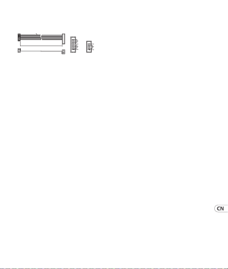
电源连接
该模块配备了连接到标准 Eurorack 电源系
统所需的电源线。 按照这些步骤将模块连
接到您的 Eurorack 案例。
1. 关闭电源或机架外壳电源并断开电
源电缆。
2. 将电源线上的 16 针连接器插入电源
或机架盒上的插座中。 连接器有一
个选项卡, 该选项卡将与插座中的间
隙对齐, 因此不能错误地插入该选
项卡。 如果电源没有钥匙插座, 请务
必将引脚 1 (-12 V) 定向到电缆上的红
色条纹上。
3. 将 10 针连接器插入模块背面的插
座中。 连接器有一个选项卡, 该选项
卡将与插座对齐以获得正确的方向。
4. 电源线的两端牢固连接后, 您可以在
情况下安装模块并打开电源。
HOT USED
Red Stripe
200 mm ± 10
15 16
21
P2P1
2
10 9
1
Connect end P1 to the module socket
Connect end P2 to the power supply
+ 12V
- 12V
GROUND
+ 12V
- 12V
GROUND
安装
必要的螺丝包含在用于安装在欧洲拉克箱
中的模块中。 安装前连接电源线。
根据机架外壳的不同, 可能会有一系列固
定孔, 沿着机箱的长度间隔 2 HP, 或允许单
个螺纹板沿外壳长度滑动的轨道。 自由移
动的螺纹板允许模块的精确定位, 但在连
接螺丝之前, 每个板应定位在与模块安装
孔的大致关系中。
将模块与 Eurorack 导轨对立, 以便每个安
装孔与螺纹导轨或螺纹板对齐。 将螺丝
部分连接以开始, 这将允许在调整它们
时对定位进行小调整。 确定最终位置后,
拧紧螺丝。
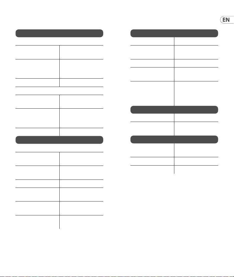
Specications
Inputs
CV in
Type
4 x 3.5 mm TS jacks,
DC coupled
Impedance
>1 MΩ,
unbalanced,
half normalled
Max input level 10 V p-p
In
Type
4 x 3.5 mm TS jack,
DC coupled
Impedance
30 kΩ, 15 kΩ with
boost enabled,
unbalanced
Max input level +19 dBu
Outputs
Out
Type
4 x 3.5 mm TS jack,
DC coupled
Impedance
100 Ω, unbalanced,
half normalled
Max output level +19 dBu
Output noise at
unity gain
-92 dBu,
22 Hz-22 kHz
Output noise at
full attenuation
-98 dBu,
22 Hz-22 kHz
Maximum
attenuation
-97 dB at 1 kHz
Controls
CV attenuator -∞ to unity gain
Exp/Lin
Exponential to
linear CV response
Level -∞ to unity gain
Boost switch
Adds +6 dB
input gain
CV LED
Green =
positive CV,
Red =
negative CV
Power
Power supply Eurorack
Current draw
100 mA (+12 V),
100 mA (-12 V)
Physical
Dimensions
60.6 x 129 x 41.3 mm
(2.39 x 5.08 x 1.63")
Rack units 12 HP
Weight 0.14 kg (0.31 lbs)
59Quick Start Guide58 FOUR PLAY
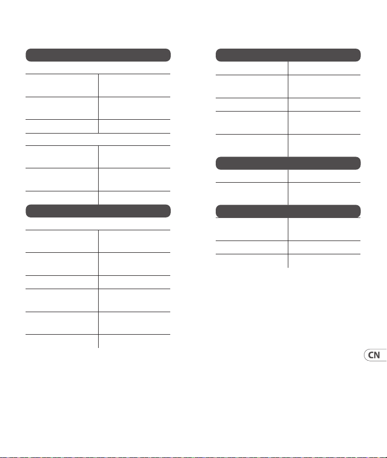
技术参数
输入
简历输入
类型
4 x 3.5 mm
TS
插孔, 直流耦合
阻抗
>1 MΩ, 不平衡,
半标准化
最大输入电平
10 V p-p
在
类型
4 x 3.5 mm
TS
插孔, 直流耦合
阻抗
30 kΩ, 15 kΩ 启用
升压, 不平衡
最大输入电平
+19 dBu
输出
出去
类型
4 x 3.5 mm
TS
插孔, 直流耦合
阻抗
100 Ω, 不平衡,
半标准化
最大输出电平
+19 dBu
单位增益下的输
出噪声
-92 dBu,
22 Hz-22 kHz
全衰减时的输
出噪声
-98 dBu,
22 Hz-22 kHz
最大衰减
-97 dB 在 1 kHz
控件
恒压衰减器
-∞ 到单位增益
进出口
对线性 CV 响应
的指数
等级
-∞ 到单位增益
升压开关
增加 +6 dB 输入
增益
恒压 LED
绿色 = 正 CV,
红色 = 负 CV
力量
电源供应 欧洲机架
当前平局
100 mA (+12 V)、
100 mA (-12 V)
身体的
方面
60.6 x 129 x 41.3 mm
(2.39 x 5.08 x 1.63”)
机架单元
12 HP
重量
0.14 kg (0.31 lbs)
61Quick Start Guide60 FOUR PLAY
63Quick Start Guide62 FOUR PLAY
FEDERAL COMMUNICATIONS
COMMISSION COMPLIANCE
INFORMATION
Responsible Party Name: Music Tribe
Commercial NV Inc.
Address: 122 E. 42nd St.1,
8th Floor NY,
NY 10168,
United States
Email Address: [email protected]
FOUR PLAY
This equipment has been tested and found to comply
with the limits for a Class B digital device, pursuant
to part 15 of the FCC Rules. These limits are designed
to provide reasonable protection against harmful
interference in a residential installation. This equipment
generates, uses and can radiate radio frequency energy
and, if not installed and used in accordance with the
instructions, may cause harmful interference to radio
communications. However, there is no guarantee that
interference will not occur in a particular installation. If
this equipment does cause harmful interference to radio
or television reception, which can be determined by
turning the equipment o and on, the user is encouraged
to try to correct the interference by one or more of the
following measures:
• Reorient or relocate the receiving antenna.
• Increase the separation between the equipment
and receiver.
• Connect the equipment into an outlet on a
circuit dierent from that to which the receiver
is connected.
• Consult the dealer or an experienced radio/TV
technician for help.
This equipment complies with Part 15 of the FCC rules.
Operation is subject to the following two conditions:
(1) this device may not cause harmful interference, and
(2) this device must accept any interference received,
including interference that may cause undesired operation.
Behringer
Important information:
Changes or modications to the equipment not expressly
approved by Music Tribe can void the user’s authority to
use the equipment.
Hereby, Music Tribe declares that this product is in
compliance with General Product Safety Regulation
(EU) 2023/988, Directive 2014/30/EU, Directive 2011/65/
EU and Amendment 2015/863/EU, Directive 2012/19/
EU, Regulation 519/2012 REACH SVHC and Directive
1907/2006/EC.
Full text of EU DoC is available at https://community.
musictribe.com/
EU Representative: Music Tribe Brands DK A/S
Address: Gammel Strand 44, DK-1202
København K, Denmark
UK Representative: Music Tribe Brands UK Ltd.
Address: 8
th
Floor, 20 Farringdon Street London EC4A 4AB,
United Kingdom
Correct disposal of this product: This symbol
indicates that this product must not be
disposed of with household waste, according
to the WEEE Directive (2012/19/EU) and
your national law. This product should be
taken to a collection center licensed for the recycling
of waste electrical and electronic equipment (EEE). The
mishandling of this type of waste could have a possible
negative impact on the environment and human health
due to potentially hazardous substances that are
generally associated with EEE. At the same time, your
cooperation in the correct disposal of this product will
contribute to the ecient use of natural resources. For
more information about where you can take your waste
equipment for recycling, please contact your local city
oce, or your household waste collection service.
型号: FOUR PLAY 成器与采样器
制造商: Music Tribe Commercial FZE
Made in China 中国制造
CAN ICES–003 (B)/NMB–003 (B)
FOUR PLAY

We Hear You