
UNDERCOUNTER: Serie Premium
Guida installazione e Manuale Utente
UNDERCOUNTER: Premium Series
Installation Guide and User Manual


www.fhiaba.com · [email protected] · Info Line 800-344222
3
www.fhiaba.com · [email protected] · Info Line 800-344222
IT
INDICE
1
1.1
1.2
1.3
1.4
INDICAZIONI IMPORTANTI PER LA SICUREZZA E PER L’AMBIENTE
Avvertenze di sicurezza e potenziale pericolo
Nell’impiego quotidiano
Rispetto per l’ambiente
Pulizia, sanificazione e manutenzione distributore ghiaccio e/o acqua (se presente)
4
4
4
5
5
2
2.1
2.2
2.3
2.4
INSTALLAZIONE
Installazione
Collegamento alla rete idrica (se presente)
Collegamento alla rete elettrica
Refrigerante
5
5
5
6
6
3
3.1
3.2
PRIMA DI INIZIARE
Per conoscere bene il vostro Fhiaba
Per la sicurezza dei bambini
6
6
7
4
4.1
4.2
4.3
4.4
REQUISITI TECNICI
Caratteristiche del vano di installazione: Beverage e Wine Cellar Indoor
Caratteristiche del vano di installazione: TriMode drawers Indoor
Caratteristiche del vano di installazione: Beverage e Wine Cellar Outdoor
Caratteristiche del vano di installazione: TriMode drawers Outdoor
8
8
9
10
11
5
5.1
5.2
5.3
PREPARAZIONE ALL’INSTALLAZIONE
Trasporto nel luogo di installazione e disimballo
Allacciamento elettrico e idraulico
Supporto anti-ribaltamento
12
12
12
13
6
6.1
6.2
CERNIERA
Modificare il verso di apertura della porta (modelli Indoor)
Modificare il verso di apertura della porta (modelli Outdoor)
14
14
15
7
7.1
7.2
7.3
7.4
7.5
MONTAGGIO DEI PANNELLI
Dimensione dei pannelli decorativi
Montaggio delle maniglie
Installazione dei pannelli decorativi
Fissaggio del pannello alla porta
Fissaggio dei pannelli ai cassettoni
16
16
18
19
22
24
8
8.1
VENTILAZIONE
Ventilazione
25
25
9
9.1
APERTURA PORTA
Apertura porta
26
26
10
10.1
INSTALLAZIONE FINALE
Installazione finale
26
26
11
11.1
CARATTERISTICHE
Componenti principali
27
27
12
12.1
12.2
12.3
12.4
PRIMA DI INIZIARE
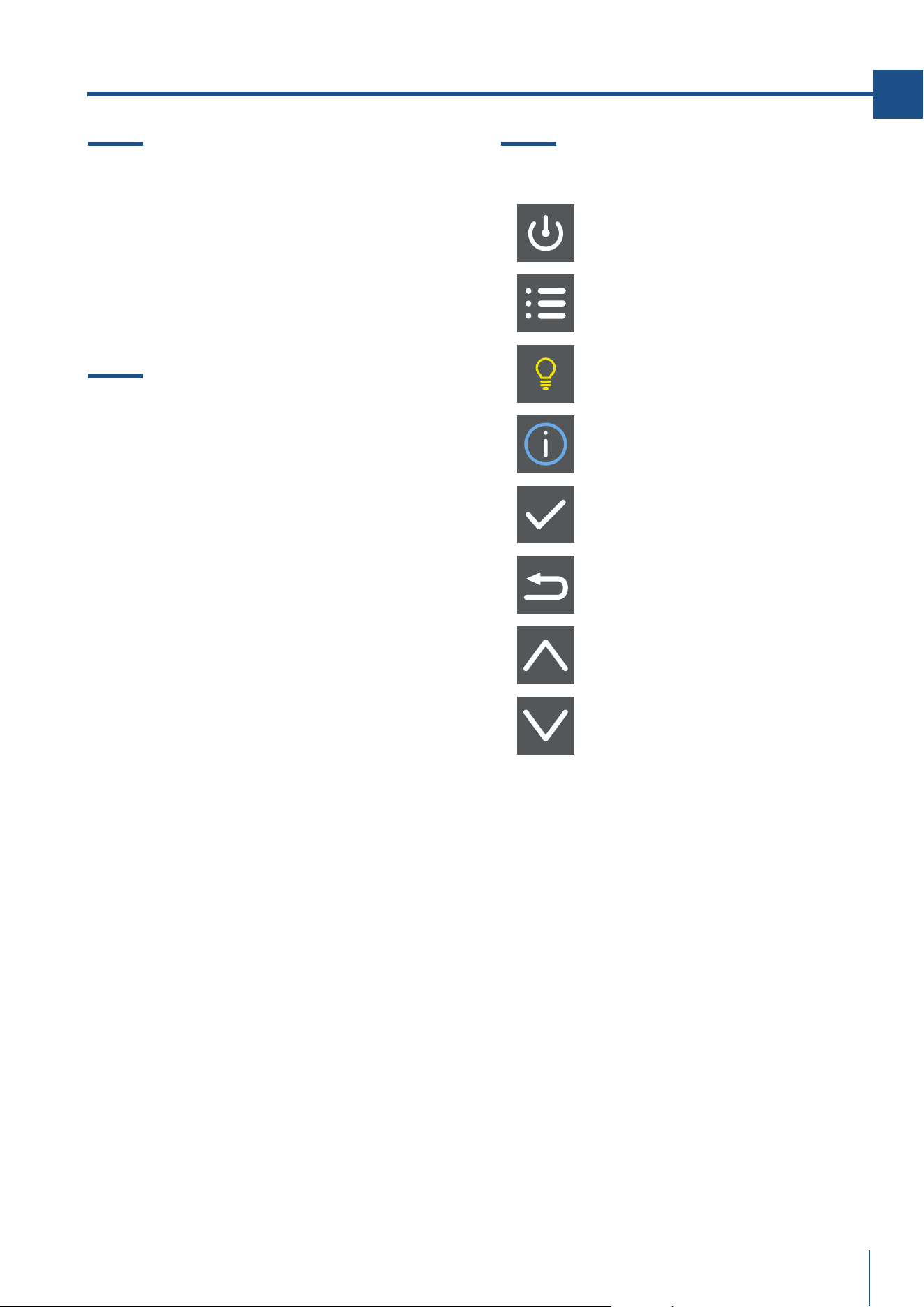
Pannello di controllo principale
Compozsizione
Funzioni
Tastiera
28
28
29
29
29
13
13.1
ACCENSIONE E SPEGNIMENTO
Accensione e spegnimento
30
30
14
14.1
REGOLAZIONI
Come regolare la temperatura secondo le diverse esigenze
30
30

4
www.fhiaba.com · [email protected] · Info Line 800-344222
15
15.1
15.2
NOTIFICHE EVENTI
Notifiche eventi
Notifiche eventi cantina vini e beverage
31
31
32
16
16.1
16.2
IMPOSTAZIONI E FUNZIONI SPECIALI
Funzioni speciali
Menu utente
33
33
33
17
17.1
ILLUMINAZIONE
Illuminazione
36
36
18
18.1
INDICAZIONI GENERALI
Indicazioni generali
36
36
19
19.1
19.2
19.3
19.4
CURA E PULIZIA
Cura e pulizia
Pulizia gliglia di ventilazione, filtro e condensatore
Pulizia interna
Sostituzione filtro carboni attivi
37
37
37
37
37

www.fhiaba.com · [email protected] · Info Line 800-344222
5
www.fhiaba.com · [email protected] · Info Line 800-344222
IT

6
www.fhiaba.com · [email protected] · Info Line 800-344222
1. INDICAZIONI IMPORTANTI PER LA SICUREZZA E PER L’AMBIENTE
1.1 Avvertenze di sicurezza
e potenziale pericolo
> Se questa apparecchiatura sostituisce un’altra già
esistente che deve essere messa da parte o smaltita,
assicurarsi che essa non diventi una pericolosa trap-
pola per i bambini.
> Questa apparecchiatura è progettata per rared-
dare bevande e cibi ed è destinata all’utilizzo dome-
stico.
> Questo apparecchio è destinato alla refrigerazione
e conservazione di alimenti freschi e surgelati in am-
biente domestico. Ogni altro uso è improprio.
> L’apparecchio non è concepito per funzionare con
temporizzatori esterni o con sistemi di comando a
distanza.
> L’apparecchiatura deve essere installata seguendo
le istruzioni riportate nella Guida all’installazione in
particolare vanno mantenute libere da ostruzioni
le aperture di ventilazione dell’apparecchiatura o
nella struttura ad incasso.
> L’apparecchiatura è dotata di un sistema di illumi-
nazione a luce concentrata con lampade Led. Non
guardare all’interno delle lampade quando sono ac-
cese per evitare possibili danni alla vista.
Questa avvertenza è riportata anche sull’etichetta
incollata all’interno della porta del frigorifero.
> Quando il freezer è in funzione non toccare le su-
perfici interne in acciaio con le mani umide o bagna-
te, in quanto la pelle potrebbe attaccarsi alle superfi-
ci particolarmente fredde.
> Non usare apparecchi elettrici di alcun tipo all’in-
terno degli scomparti per la conservazione dei cibi.
> Durante il riposizionamento dei ripiani non avvici-
nare le dita alla guida di scorrimento del ripiano.
> Non posizionare contenitori di liquidi infiammabili
nelle vicinanze dell’apparecchiatura.
> Non tentare mai di spegnere una fiamma/incendio
con acqua: spegnere l’apparecchio e coprire la fiam-
ma con una coperta ignifuga.
> Non toccare gli elementi riscaldanti all’esterno
dell’apparecchio.
> Spegnere completamente l’apparecchiatura stac-
candola dalla presa della corrente durante operazio-
ni di pulizia. Se la spina non è facilmente raggiungi-
bile è opportuno scollegare l’interruttore omnipolare
relativo alla presa cui l’apparecchiatura è collegata.
> I componenti dell’imballaggio possono essere pe-
ricolosi per i bambini: non permettere loro di giocare
con sacchetti, films plastici e polistirolo.
> Qualsiasi riparazione deve essere eettuata da un
tecnico qualificato.
> Questo apparecchio non è da intendersi adatto
all’uso da parte di persone (incluso bambini) con ri-
dotte capacità fisiche, sensoriali o mentali, o prive
di esperienza e conoscenza, a meno che siano state
supervisionate o istruite riguardo all’uso dell’appa-
recchio da una persona responsabile della loro si-
curezza. I bambini dovrebbero essere supervisionati
per assicurarsi che non giochino con l’apparecchio.
> Non danneggiare i tubi del circuito refrigerante
dell’apparecchio.
> Non introdurre nell’apparecchio bombolette spray
o recipienti che contengano propellenti o sostanze
infiammabili.
> La quantità di gas refrigerante contenuta nel vo-
stro apparecchio è indicata nella targhetta d’identi-
ficazione posta all’interno dell’apparecchio. Nel caso
in cui il cavo di collegamento elettrico dovesse subire
danni, è necessario sostituirlo, coinvolgere il servizio
assistenza clienti autorizzato o un elettricista qualifi-
cato ad eseguire questa operazione.
> Installazioni o riparazioni eseguite da personale
non autorizzato, possono potenzialmente creare pe-
ricolo per l’utente e danni all’apparecchio.
Le riparazioni vanno eseguite dal servizio assistenza
clienti autorizzato.
> È consentito usare solo parti di ricambio originali
del costruttore. Solo con l’impiego di detti compo-
nenti il costruttore garantisce che i requisiti di sicu-
rezza del prodotto siano rispettati.
> Le riparazioni devono essere eseguite solo dal
produttore, servizio assistenza autorizzato o altra
persona qualificata.
> Collegare l’apparecchio a una presa a 3 poli
collegato alla terra
> Non rimuovere il polo di messa a terra.
> Non utilizzare un adattatore.
> Non utilizzare una prolunga.
> Scollegare la fonte di alimentazione da tutti i
dispositivi prima dell’intervento.
> Se il CAVO DI ALIMENTAZIONE è danneggiato,
deve essere sostituito dal produttore, un servizio di
assistenza autorizzato o altra persona qualificata in
modo da evitare pericoli.
> I bambini devono essere sorvegliati per assicurarsi
che non giochino con l’apparecchio.
> Non modificare l’apparecchio.
> Non inserire oggetti metallici appuntiti (posate o
utensili) nelle feritoie.
> Non toccare (specialmente con le mani bagnate) o
mettere direttamente in bocca i cibi congelati.
> Non conservare sostanze infiammabili, esplosive
o che evaporano.
> Non conservare sostanze esplosive, come
bombolette spray con propellente infiammabile
all’interno dell’apparecchio.
> Le bottiglie con alta percentuale di alcol devono

www.fhiaba.com · [email protected] · Info Line 800-344222
7
www.fhiaba.com · [email protected] · Info Line 800-344222
IT
essere ben chiuse e in posizione verticale.
> Le sostanze organiche, acide e gli oli eterei
possono corrodere le superfici in plastica e le
guarnizioni se a contatto per lungo tempo.
> Non tirare mai il cavo per staccare la spina.
1.2 Nell’impiego quotidiano
> Le operazioni di pulizia e manutenzione, destina-
te ad essere eettuate dall’utilizzatore, non devono
essere eettuate dai bambini senza sorveglianza.
> Non sbrinare o pulire mai l’apparecchio con una
pulitrice a vapore. Il vapore può raggiungere parti
elettriche e provocare un cortocircuito. Pericolo di
scarica elettrica!
> Non utilizzare oggetti appuntiti o alati per rimuo-
vere gli strati di brina o ghiaccio. E’ possibile danneg-
giare i raccordi del circuito refrigerante, che rende
inservibile l’apparecchio.
Il gas fuoriuscendo per eetto della pressione, può
provocare irritazioni agli occhi.
> Non usare impropriamente lo zoccolo, i casset-
ti estraibili, le porte ecc. quale punto di appoggio o
come sostegno.
> Controllare che non rimangano incastrati oggetti
nelle porte.
> Per la pulizia estrarre la spina d’alimentazione o
disinserire l’interruttore di sicurezza. Evitare di eser-
citare trazioni sul cordone elettrico, ma impugnare
correttamente la spina.
> Conservare alcool ad alta gradazione in un con-
tenitore ermeticamente chiuso, e posto in posizione
verticale.
> Evitare che olii o grassi imbrattino parti plastiche
o le guarnizioni delle porte. I grassi aggrediscono il
materiale plastico e la guarnizione della porta
diventano fragili e porose.
> Non ostruire le aperture di passaggio dell’aria di
aereazione dell’apparecchio.
> Permettere l’uso dell’apparecchio solo a bambini
in età di 8 anni o superiore. Sorvegliare i bambini du-
rante la pulizia e la manutenzione.
> In accordo alle attuali normative, i bambini tra i
3 e gli 8 anni possono prelevare o caricare gli ali-
menti dall’apparecchio, ma si sconsiglia altamente di
permettere ai bambini sotto agli 8 anni di eettuare
queste operazioni e in generale di utilizzare l’appa-
recchio.
> Tenere lontani i bambini inferiori agli 8 anni, se non
continuamente sorvegliati, e assicurarsi che non gio-
chino con l’apparecchio.
> Non utilizzare dispositivi meccanici, elettrici, chimi-
ci diversi da quelli raccomandati dal produttore per
accelerare il processo di sbrinamento.
> Non danneggiare il circuito di refrigerazione, (nel
caso possa essere accessibile).
> Non utilizzare apparecchi elettrici all’interno degli
scomparti per la conservazione dei cibi, se questi
non sono del tipo raccomandato dal costruttore.
> In caso di danneggiamento del circuito di refrige-
razione evitare l’utilizzo di fiamme libere ed aerare
opportunamente il locale.
> Non utilizzare l’apparecchio o parti di esso diver-
samente da quanto indicato nel presente manuale.
> L’apertura della porta per lunghi periodi può cau-
sare un notevole aumento della temperatura negli
scomparti dell’apparecchio.
> Pulire regolarmente le superfici che possono veni-
re a contatto con cibo e sistemi di drenaggio acces-
sibili.
> Conservare la carne cruda e il pesce in contenitori
adatti in frigorifero, in modo che non venga in contat-
to con altri alimenti o ci goccioli sopra.
> Se l’apparecchio viene lasciato vuoto per lunghi
periodi, spegnerlo, scongelarlo, pulirlo, asciugarlo
e lasciare la porta aperta per evitare lo sviluppo di
mua al suo interno.
> Durante l’uso non appoggiare sull’apparecchio og-
getti metallici appuntiti come coltelli, forchette cuc-
chiai e coperchi.
> Sulle parti in vetro non utilizzare detergenti abra-
sivi o corrosivi (es. prodotti in polvere, smacchiatori
e spugnette metalliche).
> Non sedersi sull’apparecchio.
> Non appoggiarsi o sedersi sulla porta o su even-
tuali
cassetti aperti.
> Non fare leva sulla porta o sulla maniglia per spo-
stare l’apparecchio.
> Non utilizzare apparecchi elettrici (ad es. phon per
i capelli...) o spray per lo sbrinamento che potrebbero
deformare le parti in plastica.
> Non usare in nessun caso l’apparecchio per rinfre-
scare l’ambiente.
> Staccare sempre dalla rete elettrica l’apparecchio
in caso di guasto, manutenzione o durante la pulizia.
> Non conservare nel congelatore liquidi in lattine o
contenitori di vetro.
> Non appoggiare oggetti pesanti sulla sommità
dell’apparecchio.
8
www.fhiaba.com · [email protected] · Info Line 800-344222
1. INDICAZIONI IMPORTANTI PER LA SICUREZZA E PER L’AMBIENTE
Simbologia utilizzata nel manuale:
Nota
suggerimenti per un corretto utilizzo
dell’apparecchiatura
Importante
Indicazioni per evitare danni
all’apparecchiatura
Attenzione
indicazioni per evitare lesioni alla
persona
1.3 Rispetto per l’ambiente
> Questo apparecchio, conforme alla direttiva euro-
pea WEEE (2012/19/UE), deve essere smaltito sepa-
ratamente dagli altri rifiuti al termine del suo ciclo
di vita.
> Questo apparecchio non contiene sostanze in
quantità tali da essere ritenute pericolose per la
salute e l’ambiente, in conformità alle attuali diret-
tive europee.
> Prestare particolare attenzione alle corrette mo-
dalità di smaltimento di tutti i componenti dell’im-
ballo.
Tensione elettrica
Pericolo di folgorazione
Disattivare l’alimentazione elettrica
generale.
Staccare il cavo di alimentazione
elettrica dall’impianto elettrico.
> L’apparecchiatura non deve essere smaltita con i
rifiuti urbani. Informarsi presso i centri di raccolta
locali per lo smaltimento dei materiali riciclabili.
> In caso di smaltimento tagliare il cavo di alimen-
tazione e togliere la porta e/o cassetti di chiusura.
> Durante lo smaltimento, evitare danni al circuito
refrigerante.
> L’apparecchiatura non contiene, nel circuito refri-
gerante e nell’isolamento, sostanze nocive per lo
strato di ozono atmosferico.
> Si precisa che per l’imballaggio dell’apparecchio
vengono utilizzati materiali non inquinanti e ricicla-
bili.
> Conferire i materiali dell’imballaggio agli idonei
centri di raccolta dierenziata.
Imballi di plastica
Pericolo di soffocamento
Non lasciare incustodito l’imballaggio o
parti di esso.
Non permettere che bambini
giochino con i sacchetti di plastica
dell’imballaggio
1.4 Pulizia, sanificazione e manutenzione
distributore ghiaccio e/o acqua
(se presente)
> Gli interventi tecnici devono essere eettuati solo
da personale qualificato o dal Servizio Assistenza
Tecnica.
Attenzione
Per evitare la contaminazione del cibo, per
favore si rispetti le seguenti istruzioni:
> Aprire la porta per un lungo periodo può
causare un elevarsi della temperatura nei
compartimenti dell'apparecchiatura.
> Pulire regolarmente le superfici che pos-
sono entrare in contatto con cibo e accessi-
bili ai sistemi di drenaggio.
> Pulire la vaschetta d'acqua se non usa-
ta per 48h. Svuotare il sistema connesso
all'acqua. Cambiare acqua se non è stata
usata per 5 giorni.
> Conserva carne cruda e pesce in con-
tenitori adatti nel frigo così che non sia in
contatto, e che non coli su altro cibo.
> Compartimenti freezer a due stelle per
cibo congelato sono adatti per conservare
cibi pre-congelati o per conservare o fare
gelato e per fare cubetti di ghiaccio.
> I compartimenti freezer a una, due e tre
stelle non sono adatti per congelare cibo
fresco.
> Se il freezer rimane vuoto per lunghi
periodi, spegnere, scongelare, pulire,
aìsciugare e lasciare il cassetto aperta per
prevenire la formazione di mua all'interno
della macchina.
www.fhiaba.com · [email protected] · Info Line 800-344222
9
www.fhiaba.com · [email protected] · Info Line 800-344222
IT
1. INDICAZIONI IMPORTANTI PER LA SICUREZZA E PER L’AMBIENTE
1.5 Informazioni per gli enti di controllo
> Per le verifiche EcoDesign, l’installazione e la pre-
parazione dell’apparecchio devono essere conformi
alla normativa EN 62552.
> I requisiti di ventilazione, dimensioni e spazio mi-
nimo dalla parete posteriore sono indicati nel capi-
tolo “Installazione” del presente manuale.
> Contattare il costruttore per ulteriori informazioni.
1.6 Per risparmiare energia
> L’uso adeguato dell’apparecchio, l’imballo corretto
degli alimenti, la temperatura costante e l’igiene de-
gli alimenti influisce sulla qualità di conservazione.
> Ridurre il tempo e il numero di aperture delle
porte per evitare un eccessivo riscaldamento delle
celle.
> Pulire periodicamente il condensatore per evitare
perdite di ecenza della macchina. (vedi cap. 10.3)
> Scongelare i surgelati nella cella frigorifera per
recuperare in essa il freddo accumulato dagli ali-
menti congelati.
1.7 Etichettatura ambientale
LEGENDA MATERIALI DELL'IMBALLO
MaterialeA bbreviazione Numerazione
A
Polietilene a
bassa densità
LLDPE 4
B
Cartone non
ondulato
PAP2 1
C
Polistirolo
PS 6
D
Legno
FOR 50
E
Ferro
FE 40
F
Polivinile di
cloruro
PVC3
G
Polipropilene
tereftalato
PET 1
H
Cartone
ondulato
PAP2 0
C
C
D
E
B
A
A
G
H
F
10
www.fhiaba.com · [email protected] · Info Line 800-344222
2. INSTALLAZIONE
2.1 Installazione
Assicuratevi che l’installazione sia eettuata cor-
rettamenteda tecnici specializzati, rispettando tutte
le indicazioni riportate nella specifica guida di in-
stallazione fornita con l’apparecchiatura.
Attenzione
Eseguire l’allacciamento idraulico
assolutamente prima di quello elettrico.
> È obbligatorio il collegamento di terra secondo le
modalità previste dalle norme di sicurezza dell'im-
pianto elettrico.
> Posizionare l’apparecchio con l’aiuto di una se-
conda persona.
> Non usare la porta aperta come leva per posizio-
nare l’apparecchio.
> Non esercitare pressioni eccessive sulla porta
aperta.
> L’apparecchio non deve essere posizionato vicino
a fonti di calore. Se questo non è possibile, è neces-
sario utilizzare un adeguato pannello isolante.
> L’apparecchio non deve essere esposto all’irrag-
giamento solare.
> Non collocare l’apparecchio in ambienti esterni.
> Far eseguire l’installazione e gli interventi di as-
sistenza da personale qualificato nel rispetto delle
norme vigenti.
> Far eseguire il collegamento elettrico a personale
tecnico abilitato.
> Per evitare qualsiasi pericolo, se il cavo di alimen-
tazione elettrica è danneggiato, contattare subito
il servizio di assistenza tecnica che provvederà a
sostituire il cavo, in modo da prevenire ogni rischio.
> Prima di ogni intervento sull’apparecchio (instal-
lazione, manutenzione, posizionamento o sposta-
mento), munirsi sempre di dispositivi di protezione
individuale.
> Prima di ogni intervento sull’apparecchio, disatti-
vare l’alimentazione elettrica generale.
> Se installato vicino ad un altro frigorifero fare ri-
ferimento alla guida di installazione.
> Non tentare mai di riparare l’apparecchio da soli o
senza l’intervento di un tecnico qualificato.
> Non installare/utilizzare l’apparecchio all’aperto.
> ATTENZIONE: Durante il posizionamento
dell'elettrodomestico, accertarsi che il cavo di
alimentazione non sia impigliato o danneggiato.
> Per evitare instabilità dell’apparecchio, in-
stallarlo e fissarlo correttamenteome da istru-
zioni contenute nel manuale di installazione.
> Questo apparecchio può essere utilizzato fino ad
un altezza massima di 2000 metri sopra il livello
del mare.
2.2 Collegamento alla rete idrica
I modelli dotati di dispositivo per la produzione di
cubetti di ghiaccio (Ice Maker) richiedono il collega-
mento alla rete idrica domestica.
Esso va realizzato utilizzando il nuovo tubo di carico
acqua con filetto da ¾” for nito in dotazione.
La pressione in rete deve essere compresa tra 0.05
MPa e 0.5 MPa (tra 0.5 bar e 5 bar).
Pressioni di esercizio diverse possono portare a
malfunzionamenti o a perdite nel circuito idraulico.
ALLACCIAMENTO ELETTRICO E IDRAULICO
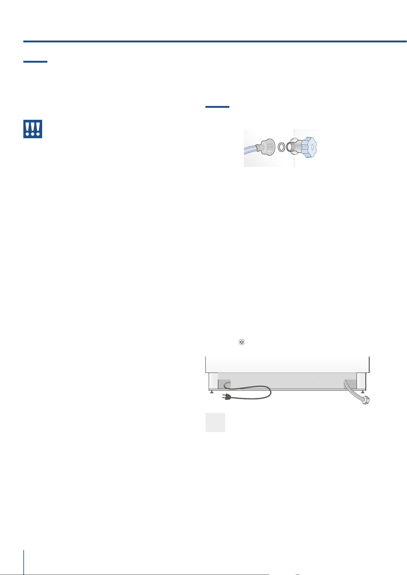
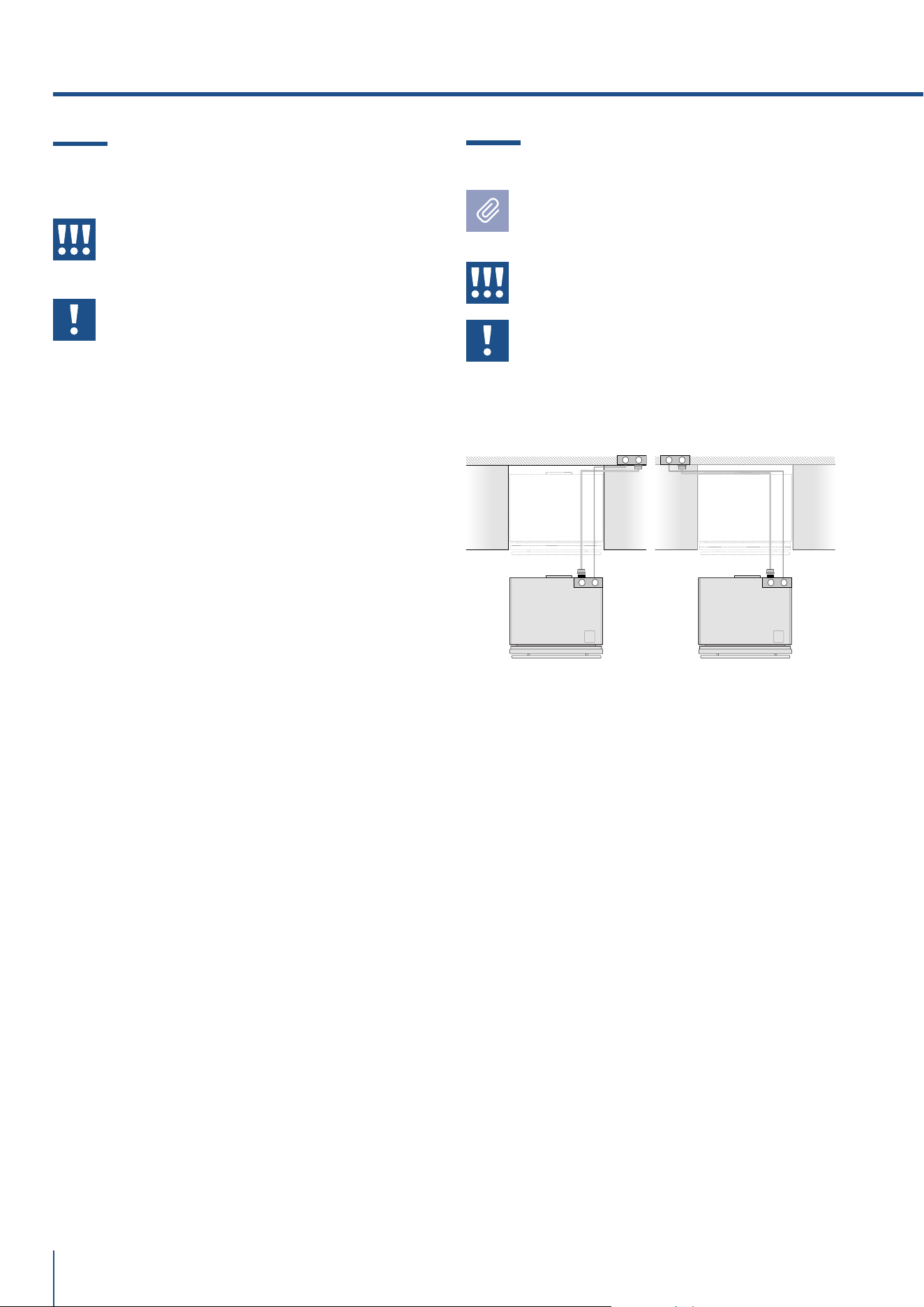
DIETRO L’APPARECCHIATURA
Operare nel modo seguente:
> Srotolare il cavo elettrico e collegarlo direttamente
alla presa a muro.
> Controllare che l’apparecchiatura sia in Stand by e
che le luci siano spente; in caso contrario premere il
tasto Unit
per spegnere l’apparecchiatura.
> Allacciare il tubo dell’acqua al frigorifero nella zona
posteriore, utilizzando il raccordo da 3/4” fornito in
dotazione [ 1 ] .
> Collegare il tubo al rubinetto utilizzando il raccordo
da 3/4” fornito in dotazione [ 2 ].
> Solo sui modelli 0FZ, installare il supporto per filtro
acqua esternamente all’apparecchitura, utilizzando i
raccordi forniti in dotazione.
Retro dell’apparecchiatura
www.fhiaba.com · [email protected] · Info Line 800-344222
11
www.fhiaba.com · [email protected] · Info Line 800-344222
IT
2.3 Collegamento alla rete elettrica
L’apparecchiatura è dotata di una spina del tipo
Schuko da 16A e deve essere collegata alla rete elet-
trica attraverso una corrispondente presa Schuko.
Non utilizzare prolunghe e/o adattatori multipli per
il collegamento.
Importante
Non utilizzare prolunghe e/o adattatori
multipli per il collegamento.
Attenzione
In presenza di reti elettriche gestite con
energie alternative, è obbligatorio in-
stallare il Kit Energie Alternative per in-
tegrare l’apparecchiatura nella rete elet-
trica.
2.4 Refrigerante
Fare attenzione a non danneggiare il circuito refri-
gerante.
Esso contiene isobutano (R600a), un gas naturale
con un alto livello di compatibilità ambientale, tut-
tavia il gas è infiammabile.
> Nel caso di danno al circuito refrigerante, assicu-
rarsi che non si sviluppino fiamme libere e scintille
nel locale. Aerare bene l’ambiente.
ISO 7010 W021
Attenzione
Rischio di incendio / materiali
infiammabili.
Prestare attenzione durante il trasporto,
montaggio o pulizia di non danneggiare
il circuito di refrigerazione.
1
2
Attenzione
L’apparecchiatura va alimentata solo
con acqua potabile.
Attenzione
Assicuratevi che l’installazione sia effet-
tuata correttamente, rispettando tutte le
indicazioni riportate nello specifico ma-
nuale di installazione fornito con l’appa-
recchiatura.
Attenzione
Non tentare di utilizzare un adattatore
filettato da giardino o un tubo di alimen-
tazione intrecciato, esso rovina le filet-
tature della connessione acqua sull’ap-
parecchio.

12
www.fhiaba.com · [email protected] · Info Line 800-344222
3. PRIMA DI INIZIARE
3.1 Per conoscere bene il vostro Fhiaba
Congratulazioni per aver acquistato il vostro nuovo
Fhiaba: da oggi potrete utilizzare il nostro innovativo
sistema di conservazione, che vi permetterà di pre-
servare nel migliore dei modi gli alimenti che desi-
derate.
Questo Manuale Utente risponderà alla maggior par-
te delle vostre domande circa le caratteristiche del
prodotto e del suo funzionamento.
3.2 Responsabilità del produttore
Il costruttore declina ogni responsabilità per danni
subiti da persone e cose causati da:
> uso dell’apparecchio diverso da quello previsto;
> inosservanza delle prescrizioni del manuale d’uso;
> manomissione anche di una singola parte dell’ap-
parecchio;
> utilizzo di ricambi non originali.
3.3 Servizio assistenza
> In caso di guasto dell'apparecchio contattare il ser-
vizio di assistenza tecnica e far eseguire la riparazio-
ne solamente a personale qualificato.
> Assicurarsi di disporre del modello e del numero
di serie disponibili sulla targhetta di identificazione.
> Utilizzare solamente ricambi originali.
> Non tentare mai di riparare l’apparecchio da soli
o senza l’intervento di un tecnico qualificato: oltre a
conseguenze sulla sicurezza, potrebbe annullare la
garanzia.
> I ricambi originali rilevanti per il funzionamento
secondo il corrispondente regolamento Ecodesign
sono reperibili presso il nostro servizio di assistenza
clienti per un periodo di almeno 10 anni a partire dal-
la messa in circolazione dell'apparecchio all'interno
dello Spazio economico europeo.
> Informazioni dettagliate sulla durata della garan-
zia e sulle condizioni di garanzia in ciascun Paese
sono reperibili presso il nostro servizio di assistenza
clienti, presso il proprio rivenditore o sul nostro sito
Internet.
> Qualora abbiate bisogno di ulteriori informazioni
non esitate a contattare il Centro di Assistenza Tec-
nica al:
> nostro numero verde
800-344222 (800-FHIABA)
> +39 0434 420160
> car[email protected]
> www.fhiaba.com
Importante
Prima di chiamare prendete nota del nume-
ro di serie dell’apparecchiatura, riportato
sul certificato di garanzia e sulla targa ma-
tricola che si trova all'interno del vano frigo
sul lato opposto all'apertura della porta.
3.4 Dati tecnici
Il refrigerante, il contenuto utile ed altri dati tecnici
sono indicati sulla targhetta identificativa.
Ulteriori informazioni sul modello scelto sono dispo-
nibili sul sito Internet https://www.fhiaba.com/
energylabel (solo per i Paesi dello Spazio economico
europeo). Questo link rimanda alla pagina uciale
del database europeo dei prodotti EPREL, il cui in-
dirizzo non era ancora stato pubblicato al momento
della stampa. Seguire le indicazioni relative alla ri-
cerca del modello. Si riconosce il modello dal segno
prima della barra del codice prodotto (E-Nr.) sulla
targhetta identificativa. In alternativa, l'indicazione
del modello si trova anche nella prima riga dell'eti-
chetta energetica UE.
www.fhiaba.com · [email protected] · Info Line 800-344222
13
www.fhiaba.com · [email protected] · Info Line 800-344222
IT
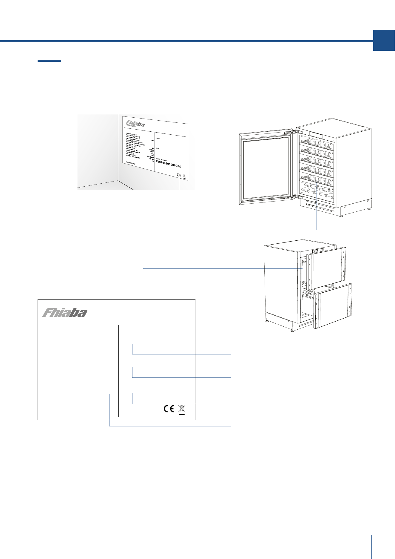
UCB602TP
Numero di serie .
Posizione della targa matricola all’interno del vano.
Modello .
Caratteristiche .
Type .
3.5 Targhetta di identificazione
La targhetta di identificazione riporta i dati tecnici,
il numero di matricola e il modello. La targhetta di
identificazione non deve mai essere rimossa.
Classe climatica di funzionamento
> SN (Subnormale) da + 10°C a + 32°C
> N (Normale) da + 16°C a + 32°C
> ST (Subtropicale) da + 18°C a + 38°C
> T (Tropicale) da + 18°C a + 43°C
La targhetta di identificazione è posizionata
all’interno dell’apparecchiatura in basso a sinistra.
La targhetta di identificazione è posizionata
all’esterno del cassetto superiore a sinistra.
Gross capacity (l)
Net capacity Fridge (l)
Net capacity Fresco (l)
Net capacity Freezer(l)
Freezing Capacity (kg/12h)
Refrigerant Fridge/Fresco (gr)
Refrigerant Freezer (gr) 30,0
Refrigerant Type
Climatic Class
Defrost Heater (W)
Total Absorbed Current (A)
Voltage (V~)
Frequenzy (Hz)
Lighting Neon/Led (W)
Temperature Rise Time
MADE IN ITALY
143
R600a
SN/T
30
1.5
220-240 V
50-60 Hz
0
MODEL
TYPE
SERIAL NUMBER
UCB602TP
F20230507000016
60 (2 23/64”)
1193 (46 31/32”)
UCW602TP: 600 (23 5/8”)
873 Min - 900 Max
(34 3/8” Min - 35 7/16” Max)
865 Min - 890 Max
(34 3/64” Min - 35 1/32” Max)
104 Min - 129 Max
(4 3/32” Min - 5 5/64” Max)
598 (23 35/64”)
556 (21 7/8”)
680 (26 49/64”)
468 (18 27/64”)
572 (22 33/63”)
21 (53/64”)740 (29 9/64”)
EE
UCB601TP: 600 (23 5/8”)
UCB602TP: 600 (23 5/8”)
UCW601TP: 600 (23 5/8”)
63 (2 31/64”)
14
www.fhiaba.com · [email protected] · Info Line 800-344222
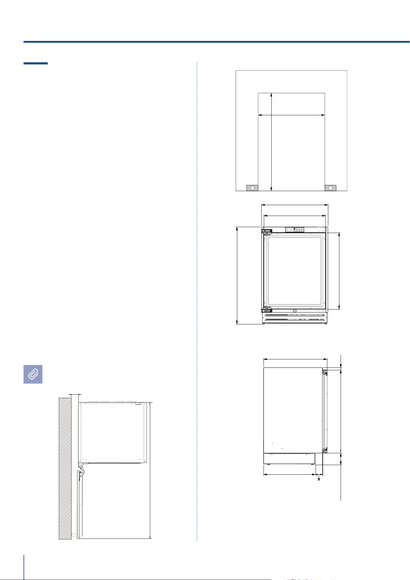
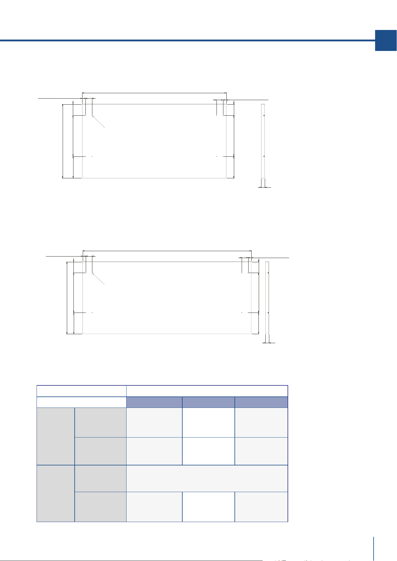
4.1 Caratteristiche del vano
di installazione: Beverage and Wine
Cellar Premium Indoor
- Integrato a scomparsa totale e pannellabile
E - spazio da riservare per passaggio cavo
Altezza nicchia
Min 873 mm - Max 900 mm
Larghezza minima nicchia
UCB601TP: 600 mm
UCB602TP: 600 mm
UCW601TP: 600 mm
UCW602TP: 600 mm
Profondità minima nicchia
600 mm
Ingombro con porta aperta
1193 mm
Angolo apertura porta
115° / 90° opzionale
Larghezza
598 mm
Altezza apparecchiatura
Min 865 mm - Max 890 mm
Profondità con porta (senza pannello)
572 mm
Le dimensioni sono in millimetri e tra
parentesi in pollici
4. REQUISITI TECNICI
961 (37 53/64”)
UC2D60P: 600 (23 5/8”)
UC2D75P: 750 (29 17/32”)
UC2D90P: 900 (35 7/16”)
UC2D60P: 598 (23 35/64”)
UC2D75P: 748 (29 29/64”)
UC2D90P: 898 (35 23/64”)
UC2D60P: 574 (22 39/64”)
UC2D75P: 724 (28 1/2”)
UC2D90P: 874 (34 13/32”)
468 (18 27/64”)
63 (2 31/64”)
572 (22 33/63”)
13 (33/64”)
4 (5/32”)
20 (25/32”)
362 (14 1/4”)362 (14 1/4”)
E E
873 Min - 900 Max
(34 3/8” Min - 35 7/16” Max)
865 Min - 890 Max
(34 3/64” Min - 35 1/32” Max)
104 Min - 129 Max
(4 3/32” Min - 5 5/64” Max)
www.fhiaba.com · [email protected] · Info Line 800-344222
15
www.fhiaba.com · [email protected] · Info Line 800-344222
IT
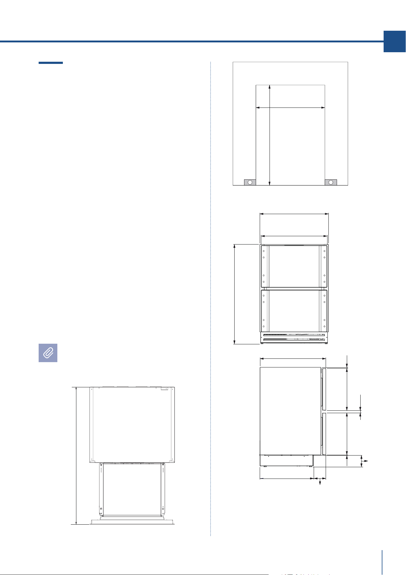
4.2 Caratteristiche del vano
di installazione: TriMode drawers
Premium Indoor
- Integrato a scomparsa totale e pannellabile
E - spazio da riservare per passaggio cavo
Altezza nicchia
Min 873 mm - Max 900 mm
Larghezza minima nicchia
UC2D60P: 600 mm
UC2D75P: 750 mm
UC2D90P: 900 mm
Profondità minima nicchia
600 mm
Ingombro con cassettoni aperti
961mm
Larghezza
UC2D60P: 598 mm
UC2D75P: 748 mm
UC2D90P: 898 mm
Altezza apparecchiatura
Min 865 mm - Max 890 mm
Profondità con porta (senza pannello)
572 mm
Le dimensioni sono in millimetri
e tra parentesi in pollici
48 (1 57/64”)
1148 (45 13/64”)
UCW602TPO: 600 (23 5/8”)
873 Min - 900 Max
(34 3/8” Min - 35 7/16” Max)
865 Min - 890 Max
(34 3/64” Min - 35 1/32” Max)
598 (23 35/64”)
499 (19 41/64”)
576 (22 43/64”)
625,4 (24 5/8”)
EE
758,5 (29 55/64”)
12 (15/32”)
12 (15/32”)
32,4 (1 9/32”)
758,5 (29 55/64”)
94,5 Min - 119,5 Max
(37 13/64” Min - 47 3/64” Max)
UCB601TPO: 600 (23 5/8”)
UCB602TPO: 600 (23 5/8”)
UCW601TPO: 600 (23 5/8”)
16
www.fhiaba.com · [email protected] · Info Line 800-344222
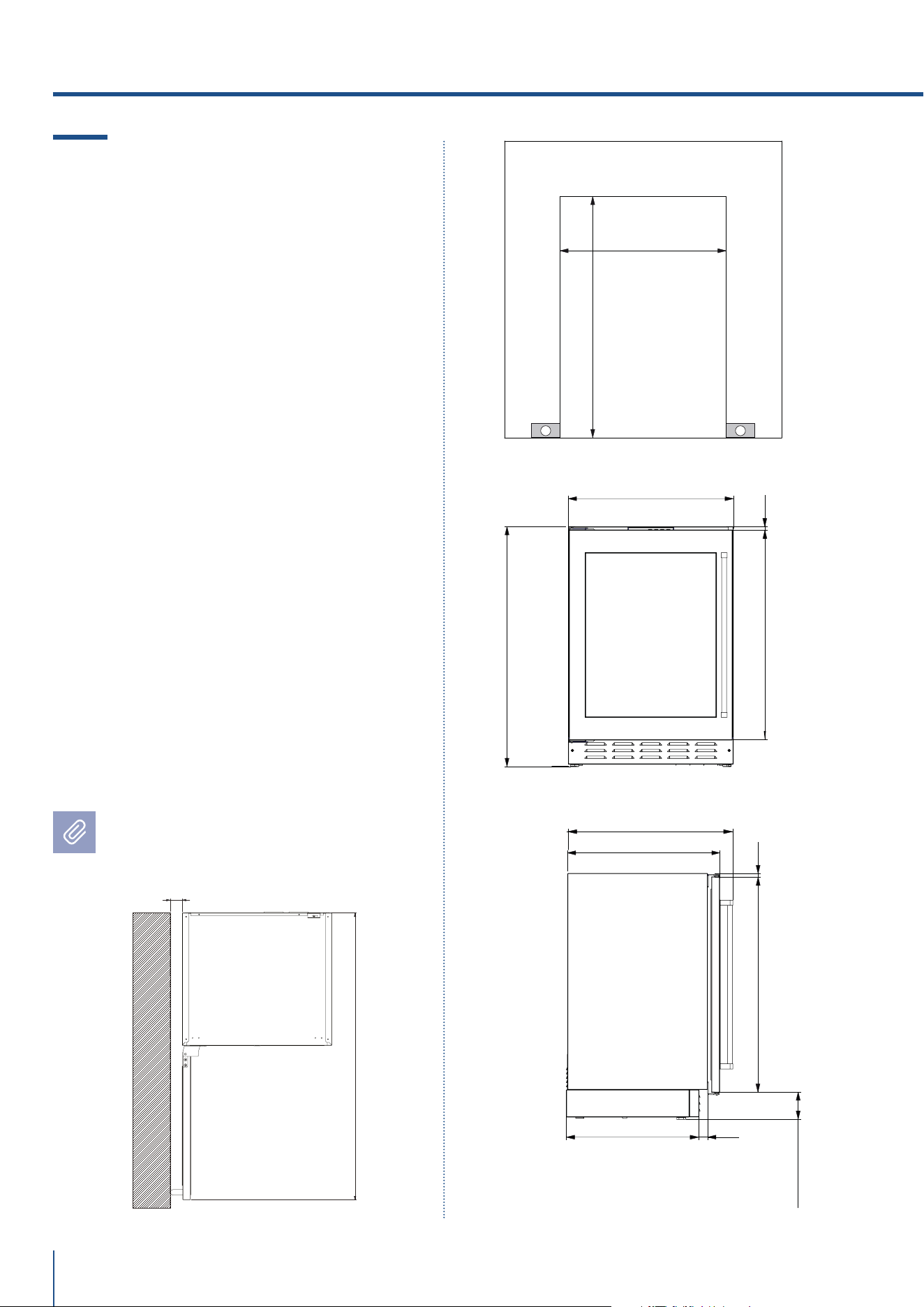
4.3 Caratteristiche del vano
di installazione: Beverage and Wine
Cellar Premium Outdoor.
- Built-in con frontale e maniglie in acciaio
E - spazio da riservare per passaggio cavo
Altezza nicchia
Min 873 mm - Max 900 mm
Larghezza minima nicchia
UCB601TPO: 600 mm
UCB602TPO: 600 mm
UCW601TPO: 600 mm
UCW602TPO: 600 mm
Profondità minima nicchia
600 mm
Ingombro con porta aperta e maniglia
1148 mm
Angolo apertura porta
115°
Larghezza
598 mm
Altezza apparecchiatura
Min 865 mm - Max 890 mm
Profondità con porta
576 mm
Le dimensioni sono in millimetri
e tra parentesi in pollici
4. REQUISITI TECNICI
958 (37 23/32”)
1008 (39 11/16”)
UC2D60PO: 581 (22 7/8”)
UC2D75PO: 741 (29 11/64”)
UC2D90PO: 891 (35 5/64”)
E E
UC2D60PO: 600 (23 5/8”)
UC2D75PO: 750 (29 17/32”)
UC2D90PO: 900 (35 7/16”)
873 Min - 900 Max
(34 3/8” Min - 35 7/16” Max)
UC2D60PO: 598 (23 35/64”)
UC2D75PO: 748 (29 29/64”)
UC2D90PO: 898 (35 23/64”)
865 Min - 890 Max
(34 3/64” Min - 35 1/32” Max)
625 (24 39/64”)
576 (22 43/64”)
7 (9/32”)
10 (25/64”)
376 (14 51/64”) 376 (14 51/64”)
96 (3 25/32”)
468 (18 27/64”)
33 (1 19/64”)
www.fhiaba.com · [email protected] · Info Line 800-344222
17
www.fhiaba.com · [email protected] · Info Line 800-344222
IT
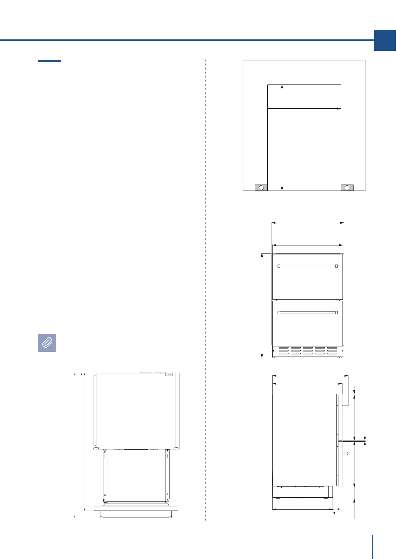
4.4 Caratteristiche del vano
di installazione: TriMode drawers
Premium Outdoor
- Built-in con frontale e maniglie in acciaio
E - spazio da riservare per passaggio cavo
Altezza nicchia
Min 873 mm - Max 900 mm
Larghezza minima nicchia
UC2D60PO: 600 mm
UC2D75PO: 750 mm
UC2D90PO: 900 mm
Profondità minima nicchia
600 mm
Ingombro con cassettoni aperti e maniglie
1008 mm
Larghezza
UC2D60PO: 598 mm
UC2D75PO: 748 mm
UC2D90PO: 898 mm
Altezza apparecchiatura
Min 865 mm - Max 890 mm
Profondità con porta
575 mm
Le dimensioni sono in millimetri
e tra parentesi in pollici
EW
E W
EW
E W
18
www.fhiaba.com · [email protected] · Info Line 800-344222
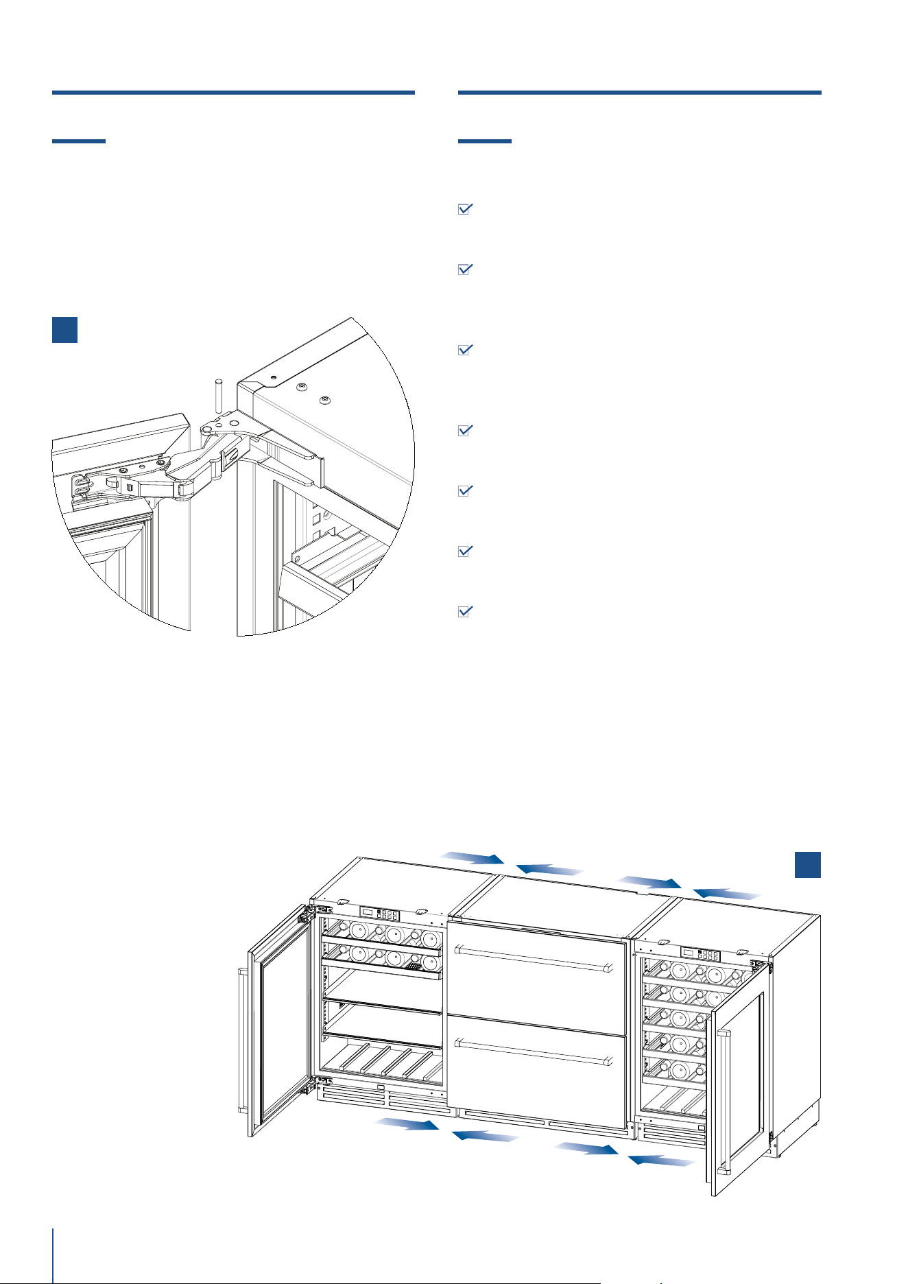
5.1 Trasporto nel luogo di installazione
e disimballo
L’apparecchiatura è molto pesante.
Usare massima attenzione durante la
movimentazione per evitare danni alle
persone e alle cose.
Trasportare l’apparecchiatura in posizio-
ne verticale.
Non trasportare mai sul lato frontale.
E’ consigliabile utilizzare un trasportatore manuale
per movimentare l’apparecchiatura fino all’area dove
verrà installata e solo a tal punto rimuovere la base
dell’imballo.
L’apparecchiatura andrebbe sempre trasportata in
posizione eretta. Se ciò non è possibile trasportare
l’apparecchiatura coricata sullo schienale.
Una volta raggiunta l’area prevista per l’installazione
rimuovere gli imballi e far scendere l’apparecchiatura
dal pallet.
5. PREPARAZIONE ALL’INSTALLAZIONE
5.2 Allacciamento elettrico e idraulico
Il filtro Fhiaba non può garantire la pota-
bilità di acqua non destinata al consumo
alimentare.
Collegare solo
ad una rete
di acqua potabile.
Non vanno utilizzate riduzioni o prolun-
ghe. Se ci fosse la necessità di chiudere il
rubinetto generale, disattivare prima l’Ice
Maker attraverso il Menu FhiabaAc-
cess (fare riferimento al Manuale d’Uso).
Per l’allacciamento elettrico va prevista una presa
Schuko da 16 A dotata di collegamento a terra e con-
trollata da un interruttore omnipolare facilmente ac-
cessibile.
Per l’allacciamento idraulico (per le apparecchiature
dotate di fabbricatore di ghiaccio) va previsto un rubi-
netto con attacco maschio da ¾”, facilmente accessi-
bile anche ad apparecchiatura installata. Per il colle-
gamento al rubinetto utilizzare esclusivamente il tubo
incluso nell’Owner’s Kit fornito con l’apparecchiatura.
L’apparecchiatura va allacciata alla rete di acqua po-
tabile, tenendo conto delle disposizioni vigenti nel pa-
ese dove viene installata l’apparecchiatura e avendo
cura di installare la cartuccia filtro acqua, fornita in
dotazione con l’apparecchiatura, seguendo le istruzio-
ni allegate.
Il tubo dell’acqua é sagomabile attraverso il riscalda-
mento (t. max 120°C/248°F), senza rischi di strozza-
ture (raggio max di curvatura di 40mm - 1 5/8”). At-
traverso il riscaldamento può poi essere nuovamente
riportato alla forma originaria.

www.fhiaba.com · [email protected] · Info Line 800-344222
19
www.fhiaba.com · [email protected] · Info Line 800-344222
IT
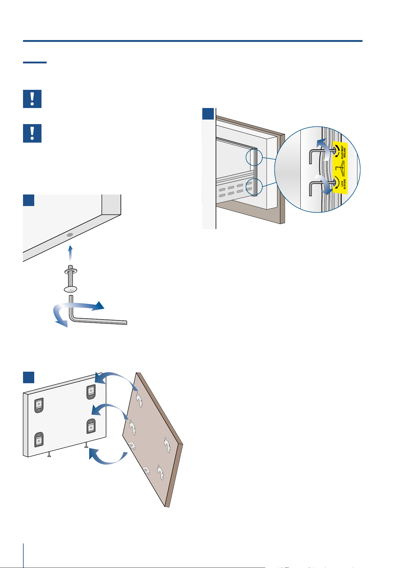
5.3 Supporto anti-ribaltamento
Il supporto anti-ribaltamento deve es-
sere installato per prevenire che l’unità
si inclini quando le porte sono completa-
mente aperte.
TOP MOUNT
Operare nel modo seguente:
Il kit per il supporto anti-inclinamento è provvisto di
un manuale per l’installazione/uso e cura:
> Sistemare il supporto anti-ribaltamento al top
dell’unita (guardare l’immagine sopra riportata)
> Posizionare l’unità all’interno del vano di installazi-
one. Mettere a livello l’apparecchiatura in allineamen-
to con il vano.
> Fissare i supporti anti-ribaltamento al piano per
bloccare l’unità.
#1#2
#1#2
20
www.fhiaba.com · [email protected] · Info Line 800-344222
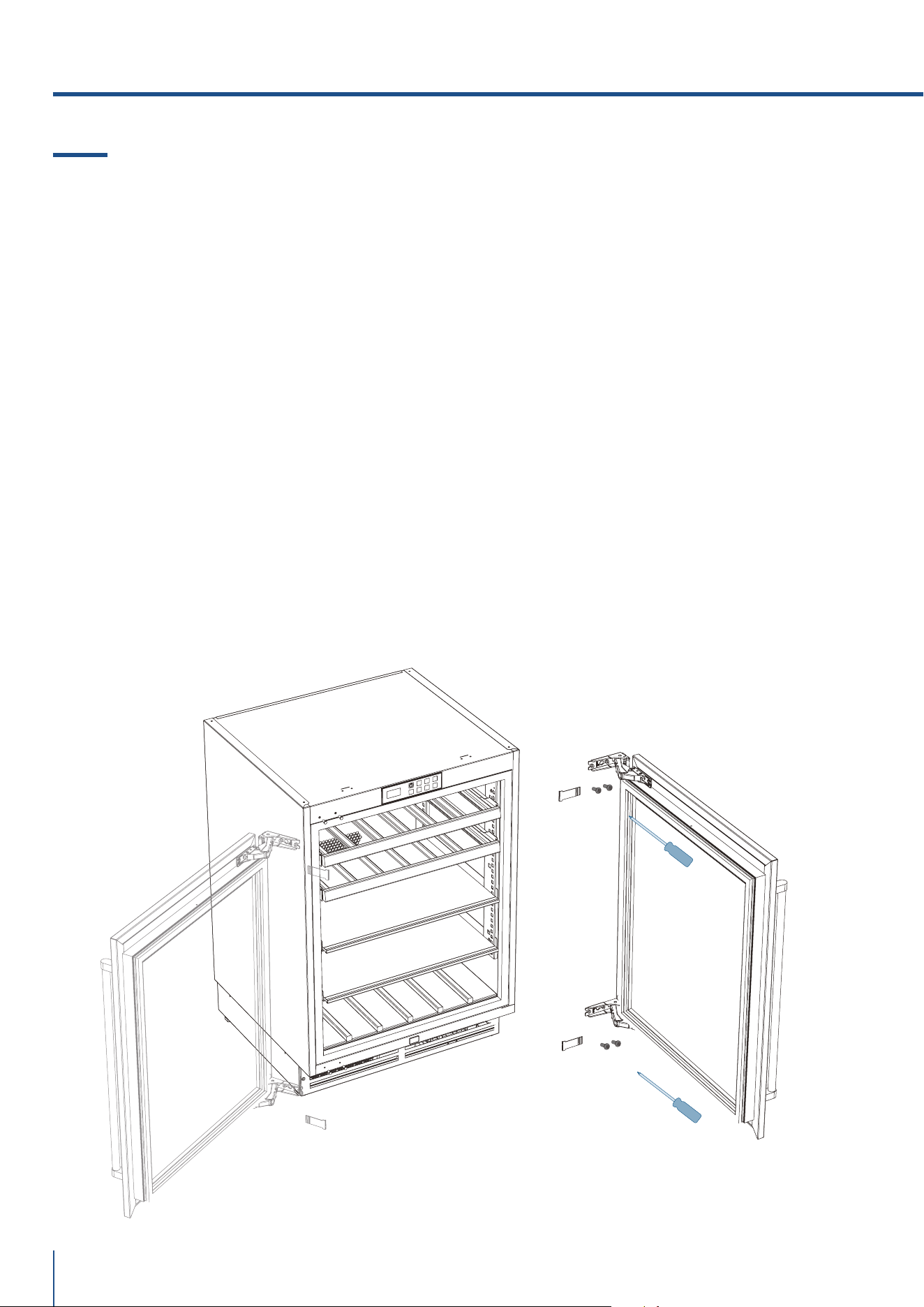
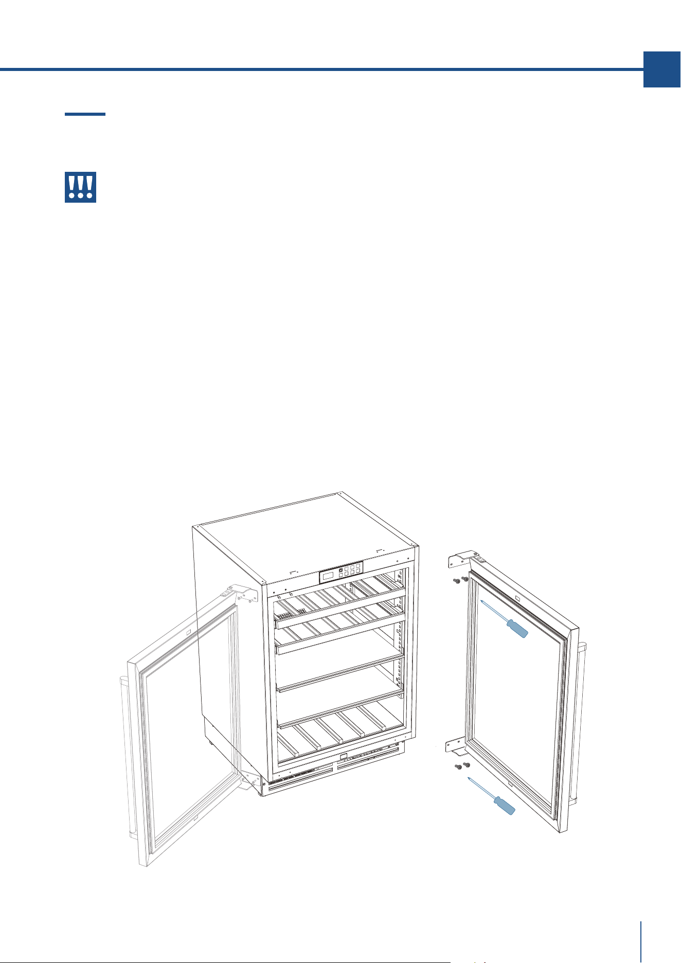
6.1 Modificare il verso di apertura della
porta (modelli Indoor)
> Aprire la porta
> Rimuovere i coperchi in plastica della cerniera.
> Supportare la porta in posizione aperta e usare un
cacciavite per rimuovere le viti #1 e #2 di entrambe
le cerniere.
> Non rimuovere mai le cerniere dalla porta.
> Rimuovere i tappi dai fori superiore e inferiore e
posizionarli nei fori sul lato opposto dell’unità.
> Re-installare parzialmente la vite #1 nei buchi
opposti dell’unità.
> Capovolgere la porta e allineare le cerniere con la
vite #1 per posizionare la porta.
> Re-installare la vite #2 e avvitare saldamente.
> Verificare che la guarnizione sia allineata con la
battuta in plastica del frontale dell’unità.
> Rimettere i coperchi in plastica sulle cerniere.
6. CERNIERA
#1#2
#1#2
www.fhiaba.com · [email protected] · Info Line 800-344222
21
www.fhiaba.com · [email protected] · Info Line 800-344222
IT
6.2 Modificare il verso di apertura della
porta (modelli Outdoor)
Le cerniere delle porte Outdoor sono a
molla e precaricate perciò non rimuovere
mai le cerniere dalla porta in acciaio inox.
> Aprire la porta
> Supportare la porta in posizione aperta e usare un
cacciavite per rimuovere le viti #1 e #2 di entrambe
le cerniere.
> Non rimuovere mai le cerniere dalla porta.
> Rimuovere i tappi dai fori superiore e inferiore e
posizionarli nei fori sul lato opposto dell’unità.
> Capovolgere la porta e allineare le cerniere con la
vite #1 per posizionare la porta.
> Re-installare la vite #2 e avvitare saldamente.
> Verificare che la guarnizione sia allineata con la
battuta in plastica del frontale dell’unità.
22
www.fhiaba.com · [email protected] · Info Line 800-344222
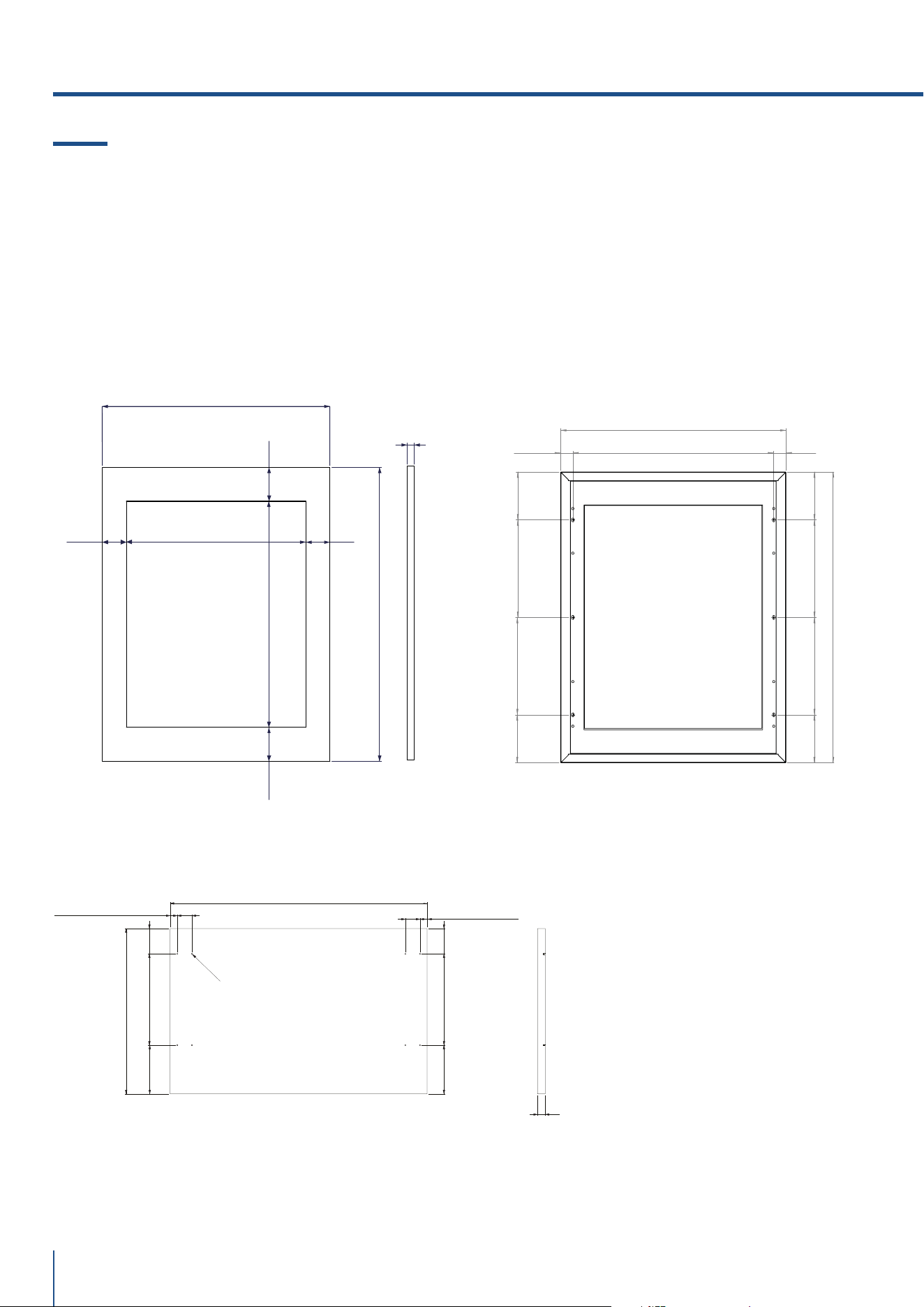
Dimensioni pannelli decorativi:
Modelli UC2D60
597 (23 1/2”)
383 (15 5/64”)
34 (1 3/8”)
17 (43/64”)
17 (43/64”)
59 (2 21/64”)
212 (8 11/32”)
212 (8 11/32”)
113 (4 29/64”)
113 (4 29/64”)
34 (1 3/8”)
59 (2 21/64”)
Ø3 (1/8”) (x8)
18 min
(45/64” min)
7. MONTAGGIO DEI PANNELLI
7.1 Dimensione dei pannelli decorativi
CORNICE INTEGRATA
Le maniglie dovrebbero essere installate al pannello
prima di installare la porta che il pannello riveste.
Lo spessore del pannello non deve essere inferiore
a 18mm e il peso dei rivestimenti non dovrebbe ec-
cedere i 10 kg (20 lbs).
Dimensioni pannelli decorativi:
Modelli UCB e UCW
Colocación de orificios en paneles decorativos.
Modelos UCB y UCW
597 (23 1/2”)
770 (30 5/16”)
471 (18 35/64”)
592,8 (23 11/32”)
63 (2 31/64”) 63 (2 31/64”)
88,6 (3 31/64”)
88,6 (3 31/64”)
18 min -20 max
(45/64”min - 25/32” max)
32,5 (1 9/32”)
532 (23 1/2”)
32,5 (1 9/32”)
258 (30 5/16”)
127 (5”)
258 (30 5/16”)
597 (23 1/2”)
770 (30 5/16”)
127 (5”)
127 (5”)
127 (5”)
258 (30 5/16”)
258 (30 5/16”)
Modelli Premium Indoor Spessore e peso pannelli decorativi
Larghezza 60 cm (24") 75 cm (30") 90 cm (36")
Modelli
UCB
UCW
Spessore
min 18mm (45/64")
max 20mm (25/32")
- -
Peso massimo max 8 kg (17 lb) - -
Modelli
UC2D60
UC2D75
UC2D90
Spessore
min 18mm (45/64")
max 25mm (1")
Peso massimo
singolo pannello
max 8 kg (17 lb) max 10 kg (22 lb) max 12 kg (26 lb)
www.fhiaba.com · [email protected] · Info Line 800-344222
23
www.fhiaba.com · [email protected] · Info Line 800-344222
IT
Dimensioni pannelli decorativi:
Modelli UC2D75
Dimensioni pannelli decorativi:
Modelli UC2D90
747 (29 13/32”)
383 (15 5/64”)
17 (43/64”)
17 (43/64”)
212 (8 11/32”)
212 (8 11/32”)
113 (4 29/64”)
113 (4 29/64”)
34 (1 3/8”) 34 (1 3/8”)
59 (2 21/64”)
59 (2 21/64”)
Ø3 (1/8”) (x8)
18 min
(45/64” min)
897 (35 5/16”)
383 (15 5/64”)
34 (1 3/8”)
17 (43/64”)
17 (43/64”)
59 (2 21/64”)212 (8 11/32”)
113 (4 29/64”)
59 (2 21/64”)212 (8 11/32”)
113 (4 29/64”)
34 (1 3/8”)
Ø3 (1/8”) (x8)
18 min
(45/64” min)

24
www.fhiaba.com · [email protected] · Info Line 800-344222
7.2 Montaggio delle maniglie
Le maniglie devono essere montate
sui pannelli prima di essere applicate
sull’aparecchiatura.
Operare nel modo seguente:
> Fare due buchi con il trapano nel retro del
pannello come nel disegno riportato sotto [ 1 ].
> Porre la maniglia sopra i buchi e inserire le viti
attraverso il pannello e dentro il supporto della
maniglia [ 2 ].
Ø 30 mm
CODICE MANIGLIA
HO8 H07 H05
Lunghezza A
794 mm
(31 1/4”)
644 mm
(25 3/8”)
494 mm
(19 5/8”)
Interasse X
480 mm
(18 7/8”)
490 mm
(19 1/4”)
340 mm
(13 3/8”)
Serie 90 75 60
Ø 18 mm
CODICE MANIGLIA
HC8 HC7 HC5
Lunghezza A
794 mm
(31 1/4”)
644 mm
(25 3/8”)
494 mm
(19 5/8”)
Interasse X
776 mm
(30 1/2”)
626 mm
(24 5/8”)
476 mm
(18 3/4”)
Serie 90 75 60
2
1
7. MONTAGGIO DEI PANNELLI
www.fhiaba.com · [email protected] · Info Line 800-344222
25
www.fhiaba.com · [email protected] · Info Line 800-344222
IT
7.3 Installazione dei pannelli decorativi
Una volta fissata l’unità all’interno della nicchia e avvi-
tate le viti dei supporti anti-ribaltamento, la macchina
non si muoverà più e sarà possibile prendere le misu-
re per il fissaggio del pannello.
> Misurare la distanza tra la cornice in alluminio della
porta e i pannelli dei mobili adiacenti. Sottrarre i milli-
metri necessari alla dimensione della fuga che si vuo-
le ottenere tra i pannelli.
> Centrare il pannello orizzontalmente e verticalmen-
te segnando dei riferimenti sullo stesso.
> Riportare le misure sul retro del pannello.
1
2
26
www.fhiaba.com · [email protected] · Info Line 800-344222
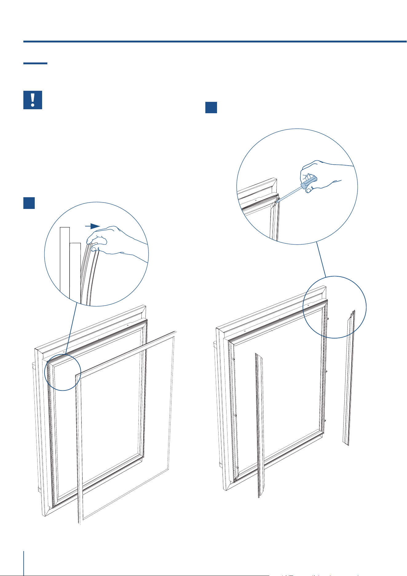
7.4 Fissaggio del pannello alla porta
Prima di iniziare l’installazione assicu-
rarsi che la maniglia sia installata al pan-
nello di rivestimento prima di posizionar-
lo sopra la porta.
Operare nel modo seguente:
> Aprire la porta e rimuovere la guarnizione con cau-
tela partendo dall’angolo. Continuare a rimuovere la
guarnizione dal canale di guarnizione [ 1 ].
> Dopo la rimozione, appoggiare la guarnizione su una
superficie piana.
> Rimuovere i due profili in plastica verticali iniziando
dall’angolo [ 2 ].
7. MONTAGGIO DEI PANNELLI
3
5
4
www.fhiaba.com · [email protected] · Info Line 800-344222
27
www.fhiaba.com · [email protected] · Info Line 800-344222
IT
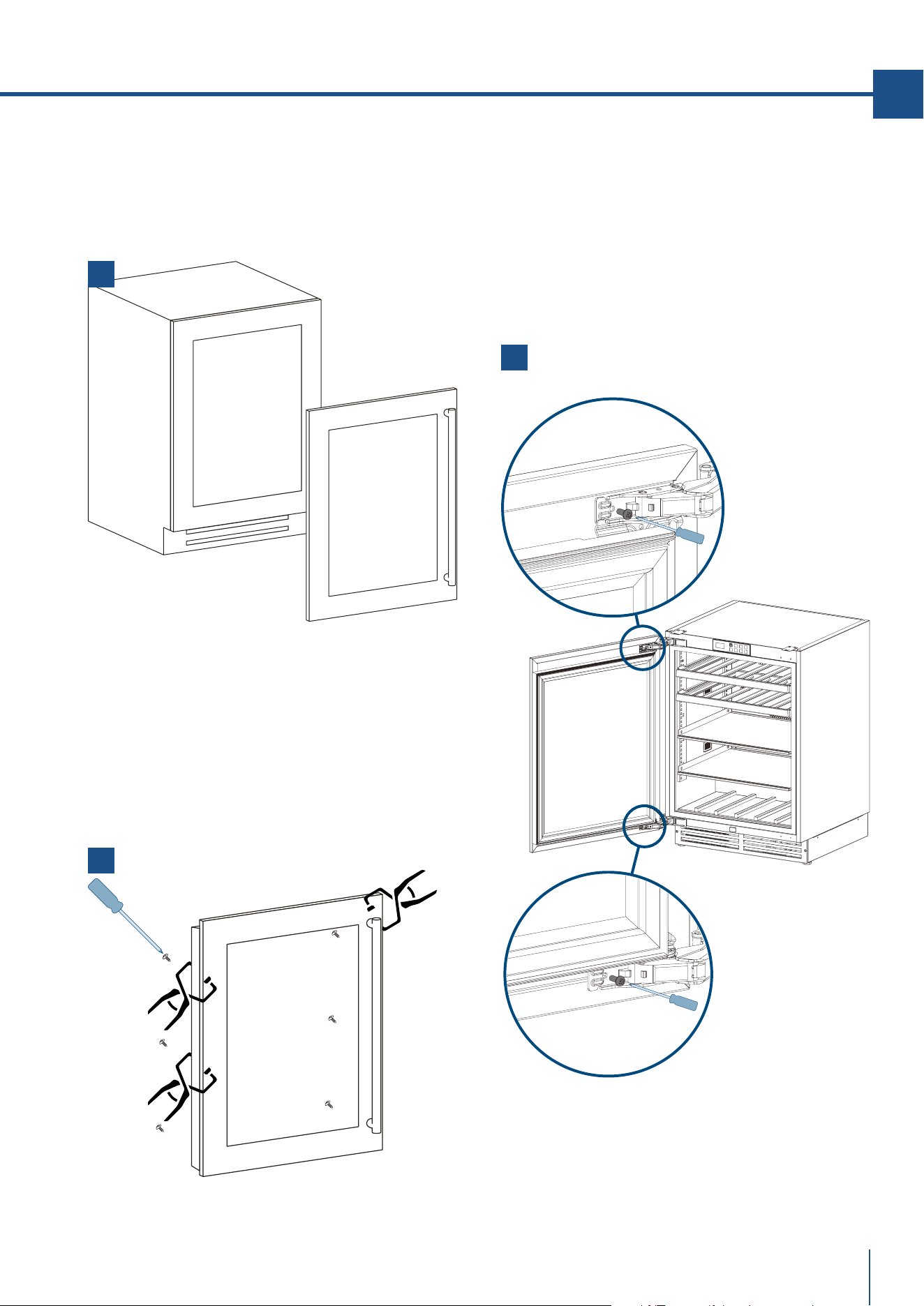
> Aprire la porta.
> Posizionare il pannello di fronte alla porta vetro ri-
spettando i riferimenti presi al punto 7.3 [ 3 ] .
> Fissare il pannello con dei morsetti.
> Localizzare 6 delle viti M5*38 mm che sono incluse
con la vostra unità [ 4 ]. Porre una vite in ognuno
dei 6 buchi e avvitarli ma non eccessivamente.
> Rimuovere i morsetti dalla porta.
> Riposizionare i supporti verticali iniziando
dall’angolo.
> Riposizionare con cura la guarnizione partendo
dall’angolo.
> Una volta verificato il corretto allineamento del pan-
nello avvitare le ultime due viti sulle cerniere [ 5 ] .
1
3
2
28
www.fhiaba.com · [email protected] · Info Line 800-344222
7. MONTAGGIO DEI PANNELLI
7.5 Fissaggio dei pannelli ai cassettoni
Prima di iniziare l’installazione assicu-
rarsi che la maniglia sia installata al pan-
nello di rivestimento prima di posizionar-
lo sopra il cassettone.
Una volta applicate le staffe e le squa-
drette ai pannelli, iniziare l’installazione
dal cassettone inferiore.
Operare nel modo seguente:
> Avvitare solo parzialmente le viti inferiori ai disposi-
tivi di fissaggio [ 1 ].
> Agganciare il pannello al cassettone partendo dalle
squadrette di regolazione inferiore [ 2 ].
> Allineamento in profondità: agendo dalla parte in-
terna del cassettone, dopo aver sollevato la guarnizio-
ne magnetica, avvicinare o allontanare il pannello dal-
la porta attraverso i fori e quindi bloccare il pannello
attraverso i fori [ 3 ].
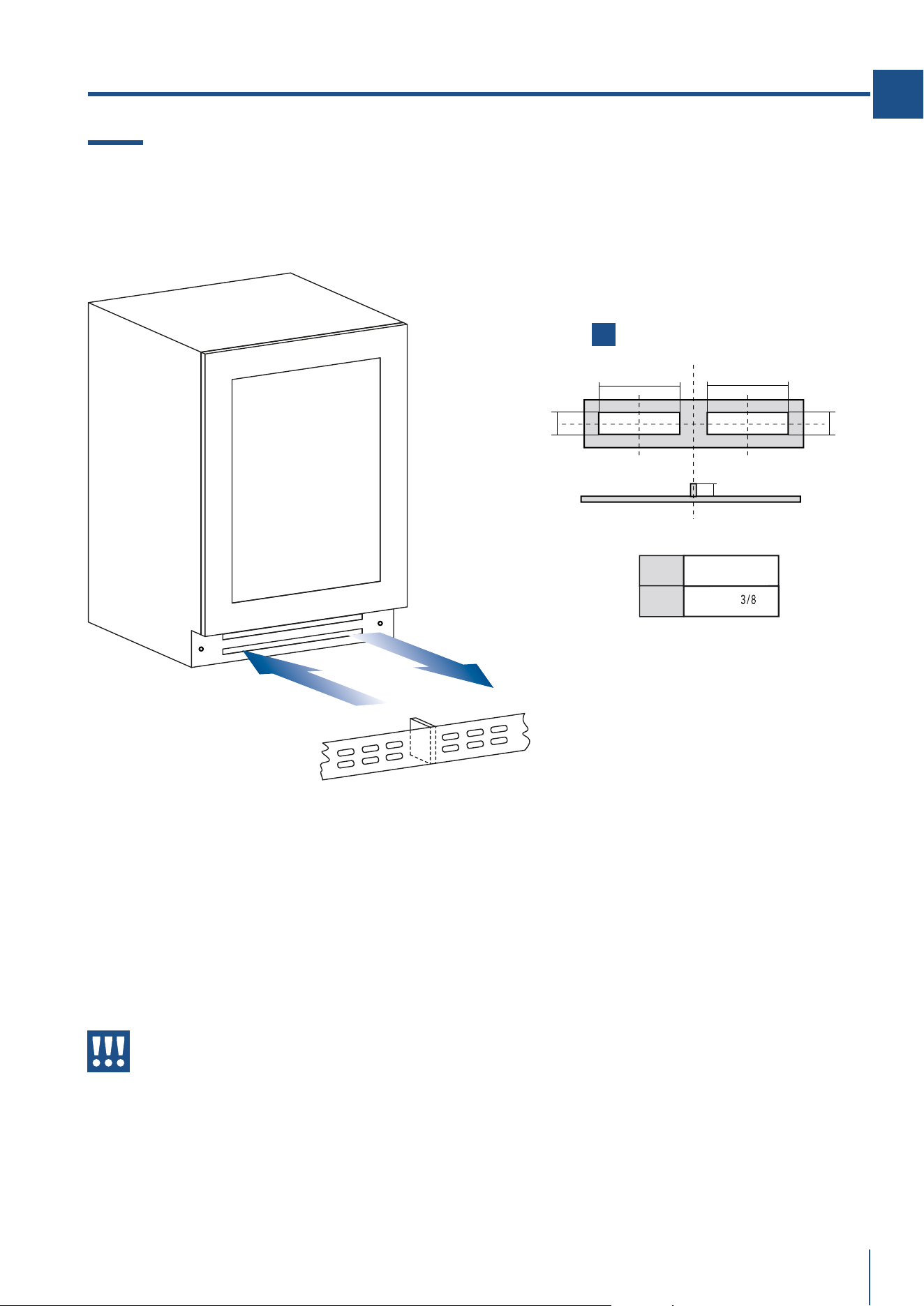
air-in
air-out
plinth
separator
1
A
BB
A
20mm
200mm (7 7
/8
")
A
B
60mm (2 ")
www.fhiaba.com · [email protected] · Info Line 800-344222
29
www.fhiaba.com · [email protected] · Info Line 800-344222
IT
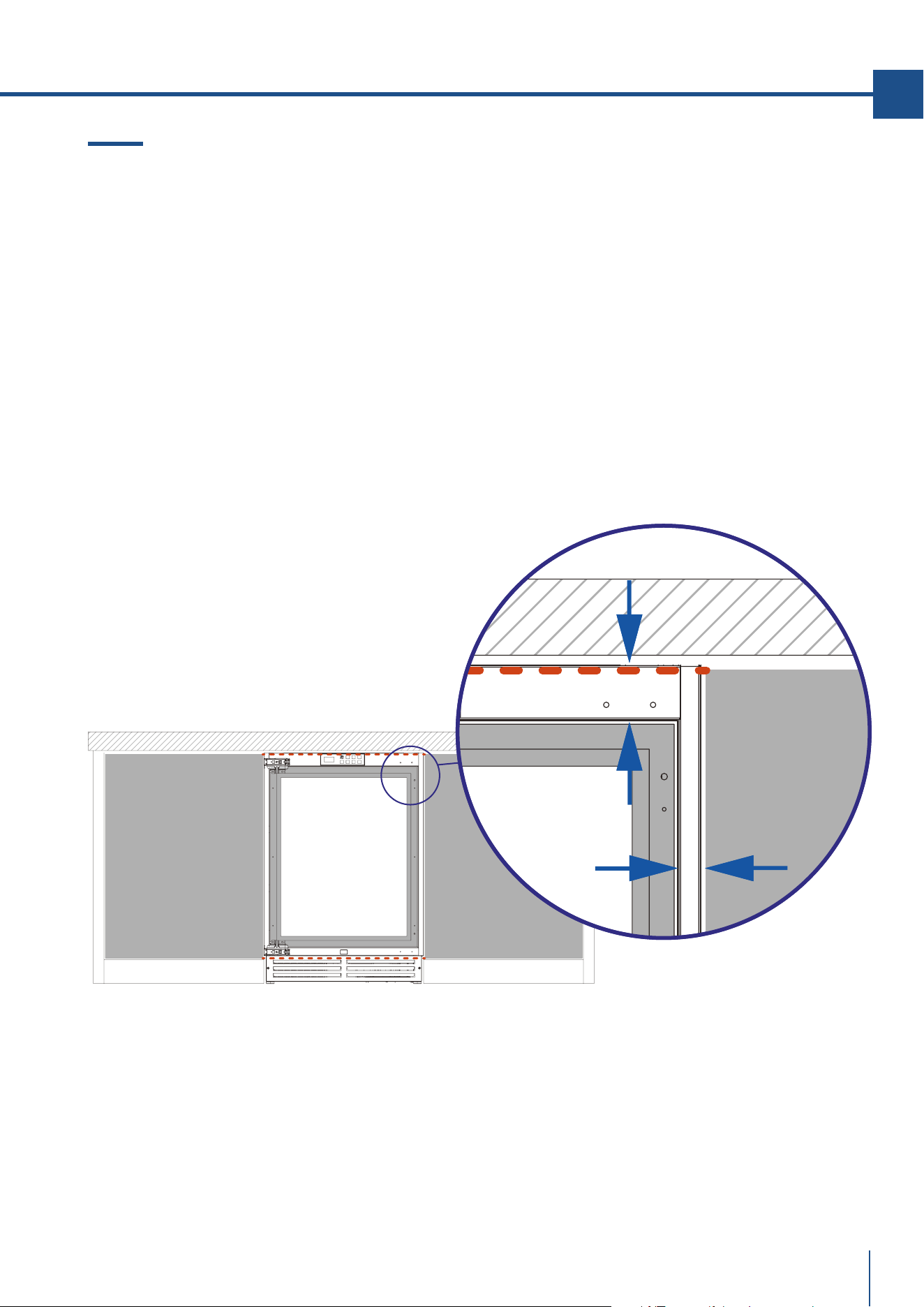
8. VENTILAZIONE
8.1 Ventilazione
Un sistema di aria forzata assicura ventilazione
attraverso una griglia posizionata nella parte inferiore
dell’unità.
Se il design della cucina include un piedistallo,
quest’ultimo deve essere perforato e separato per
mantenere un flusso di aria soddisfacente.
I buchi possono essere di qualsiasi forma e misura,
purché la parte forata equivalga al 50% del piedistallo.
[ 1 ]
L’entrata ed uscita dell’aria non deve
essere bloccata o coperta in alcuna
maniera.
30
www.fhiaba.com · [email protected] · Info Line 800-344222
9.1 Apertura porta
La porta dell’unità si aprirà a 115° dall’unità.
È possibile bloccare l’apertura a 90° usando un perno
che viene fornito insieme all’apparecchiatura e prima
di porre l’unità al di sotto del mobile.
Installazione con arresto a cerniera a 90°
> Aprire la porta a 90°
> Far scorrere il perno nel buco come dimostrato
nella foto [ 1 ]
> Potrebbe essere necessario l’uso di un martello per
inserire il perno nella posizione finale.
9. APERTURA PORTA
1
2
10.1 Controllo di fine installazione
Controllare che i piedini siano stati correttamen-
te installati.
Controllare che il collegamento all’impianto idri-
co non presenti perdite d’acqua e che il rubinetto di
chiusura sia facilmente accessibile.
Controllare che il collegamento elettrico sia rea-
lizzato correttamente e che la spina e l’interruttore
omnipolare dedicato siano facilmente accessibili.
Controllare il perfetto allineamento dell’apparec-
chiatura con i mobili adiacenti.
Controllare che ogni nastro adesivo o protezione
temporanea interna o esterna sia rimossa.
Controllare la perfetta tenuta delle porte e lo
scorrimento di cassetti e ripiani.
Controllare l’allineamento nel caso vengano in-
stallati 2 o più modelli aancati; (non sono previsti
kit di unione tra le apparecchiature). [ 2 ]
10. INSTALLAZIONE FINALE

www.fhiaba.com · [email protected] · Info Line 800-344222
31
www.fhiaba.com · [email protected] · Info Line 800-344222
IT
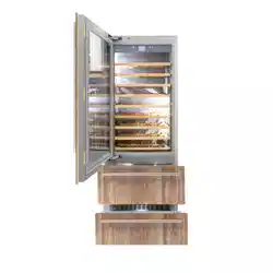
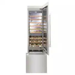
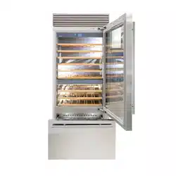
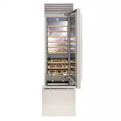
11.1 Componenti principali
BEVERAGE:
> Cella interna in acciaio inox AISI 304
> Rivestimento scocca in acciaio inox AISI 304
> Pannello comandi interattivo OLED display
> Sistema posizionamento ripiani modulare
> Cassetto in acciaio inox micropallinato con frontale in vetro temperato
> Ripiani porta bottiglie
> Illuminazione a Led bianca ed ambra
> Porta reversibile
> Porta vetro con protezione UV e gas Argon
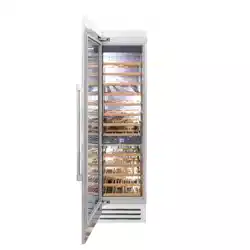
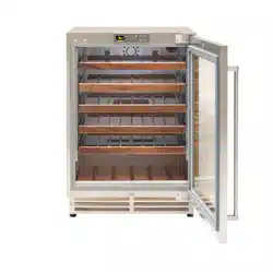
CANTINA VINI 2 TEMPERATURE:
> Cella interna in acciaio inox AISI 304
> Rivestimento scocca in acciaio inox AISI 304
> Pannello comandi interattivo OLED display
> Sistema posizionamento ripiani modulare
> Ripiani porta bottiglie
> Illuminazione a Led bianca ed ambra
> Porta reversibile
> Porta vetro con protezione UV e gas Argon
CANTINA VINI 1 TEMPERATURA:
> Cella interna in acciaio inox AISI 304
> Rivestimento scocca in acciaio inox AISI 304
> Pannello comandi interattivo OLED display
> Sistema posizionamento ripiani modulare
> Ripiani porta bottiglie
> Illuminazione a Led bianca ed ambra
> Porta reversibile
> Porta vetro con protezione UV e gas Argon
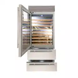
CASSETTONI TRIMODE:
> Cella interna in acciaio inox AISI 304
> Rivestimento scocca in acciaio inox AISI 304
> Pannello comandi interattivo OLED display
> Filtro acqua (*)
> Sistema posizionamento ripiani modulare
> Cassetto in acciaio inox micropallinato con frontale in vetro temperato
> Produttore ghiaccio automatico (*)
> Illuminazione a Led
> Cassettoni TriMode freezer trasformabile in vano frigorifero o vano Fre-
sco
(*) su alcuni modelli
11. CARATTERISTICHE
32
www.fhiaba.com · [email protected] · Info Line 800-344222
UNIT
ON / OFF
UNIT
ON / OFF
LIGHTLIGHT
MENUMENU INFOINFO
CONFIRMCONFIRM BACKBACK
UPUP DOWNDOWN
12.1 Pannello di controllo principale
Beverage Center 1 temperatura
Cantina vini 1 temperatura
Cassettoni TriMode / convertibili
Beverage Center 2 temperature
Cantina vini 2 temperature
12. PRIMA DI INIZIARE
www.fhiaba.com · [email protected] · Info Line 800-344222
33
www.fhiaba.com · [email protected] · Info Line 800-344222
IT
Accende/spegne l’unità
Accede al menu di principale
Accende/spegne le luci vano
Accede al menu informativo
Conferma l’operazione
Esce dal menu/Seleziona la modalità
a cifra intera o decimale solo in Cel-
sius
Up
Down
12.2 Composizione
Il pannello display è composto da un display grafico
OLED da 1.51” con risoluzione 128x64 pixel e da una
tastiera a 8 tasti resistivi con tasto di accensione/
spegnimento retroilluminato. L’ alimentazione, in
bassa tensione, proviene dalla scheda di controllo
tramite il cavo di connessione CANBUS.
12.3 Funzioni
> Visualizza il setpoint di vano o dei due vani (solo
modello CANTINA VINI/BEVERAGE CENTER)
> Visualizza le variabili di funzionamento
> Permette l’impostazione del set di temperatura
> Permette l’impostazione dei parametri funzionali
e di rete [riservato al Service]
> Notifica gli eventi di diormità così suddivisi:
> ALLARMI DI TEMPERATURA
> GUASTI
> WARNINGS
> Si connette al Cloud tramite i moduli accessori
Ethernet, Wi-Fi, 3G
12.4 Tastiera
12. PRIMA DI INIZIARE
34
www.fhiaba.com · [email protected] · Info Line 800-344222
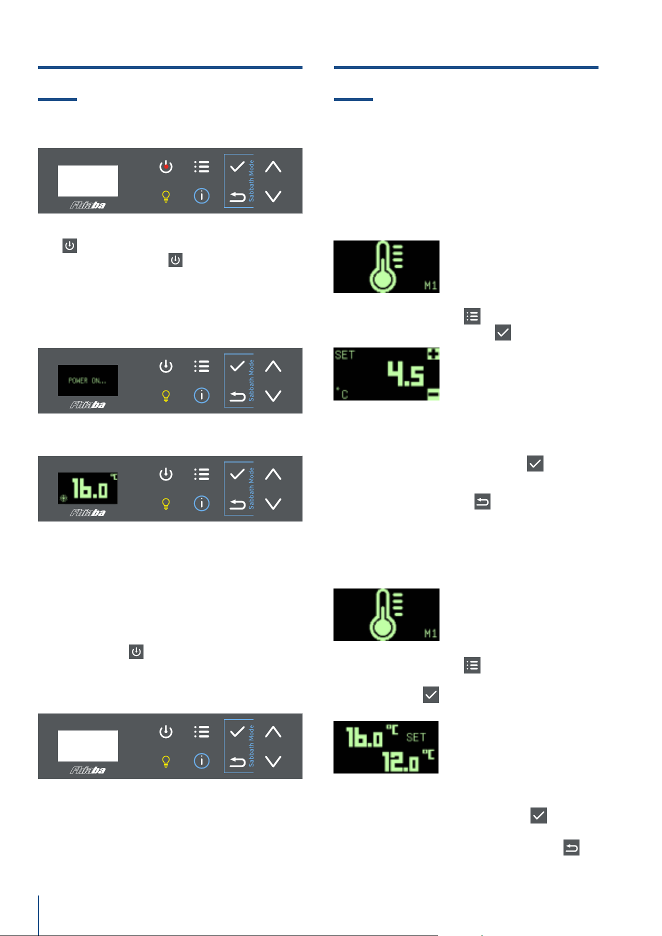
13.1 Accensione e spegnimento 14.1 Come regolare la temperatura
secondo le diverse esigenze
Lo stato di spegnimento è segnalato con il tasto ON/
OFF
retroilluminato in rosso. La pressione pro-
lungata del tasto ON/OFF
accende il dispositivo e
compare per alcuni secondi la stringa POWER ON…
Dallo stato di accensione la pressione prolungata
del tasto ON/OFF
spegne il dispositivo.
Accensione
Impostazione del setpoint
Impostazione dei setpoint per wine cellar
Spegnimento
> Premere il tasto MENU
compare il frame M1
> Premere il tasto CONFERMA
> Impostare Il nuovo valore di setpoint tramite i tasti
UP/DOWN. La conferma del nuovo valore avviene
per pressione del tasto CONFERMA
to set the
new value. Per uscire dal menu senza salvare il va-
lore premere il tasto BACK
.
> Premere il tasto MENU
compare il frame M1.
> Selezionare il setpoint da modificare tramite il ta-
sto CONFERMA
(il setpoint selezionato per la
modifica lampeggia)
> Impostare Il nuovo valore di setpoint tramite i tasti
UP/DOWN. La conferma del nuovo valore avviene
per pressione del tasto CONFERMA
. Vengono
salvati entrambi i setpoint. Per uscire dal menu
senza salvare i valori premere il tasto BACK
.
13. ACCENSIONE E SPEGNIMENTO 14. REGOLAZIONI
Beverage Center 1 temperatura
Cantina Vini 1 temperatura
Cassettoni TriMode / convertibili
Beverage Center 2 temperature
Cantina Vini 2 temperature
www.fhiaba.com · [email protected] · Info Line 800-344222
35
www.fhiaba.com · [email protected] · Info Line 800-344222
IT
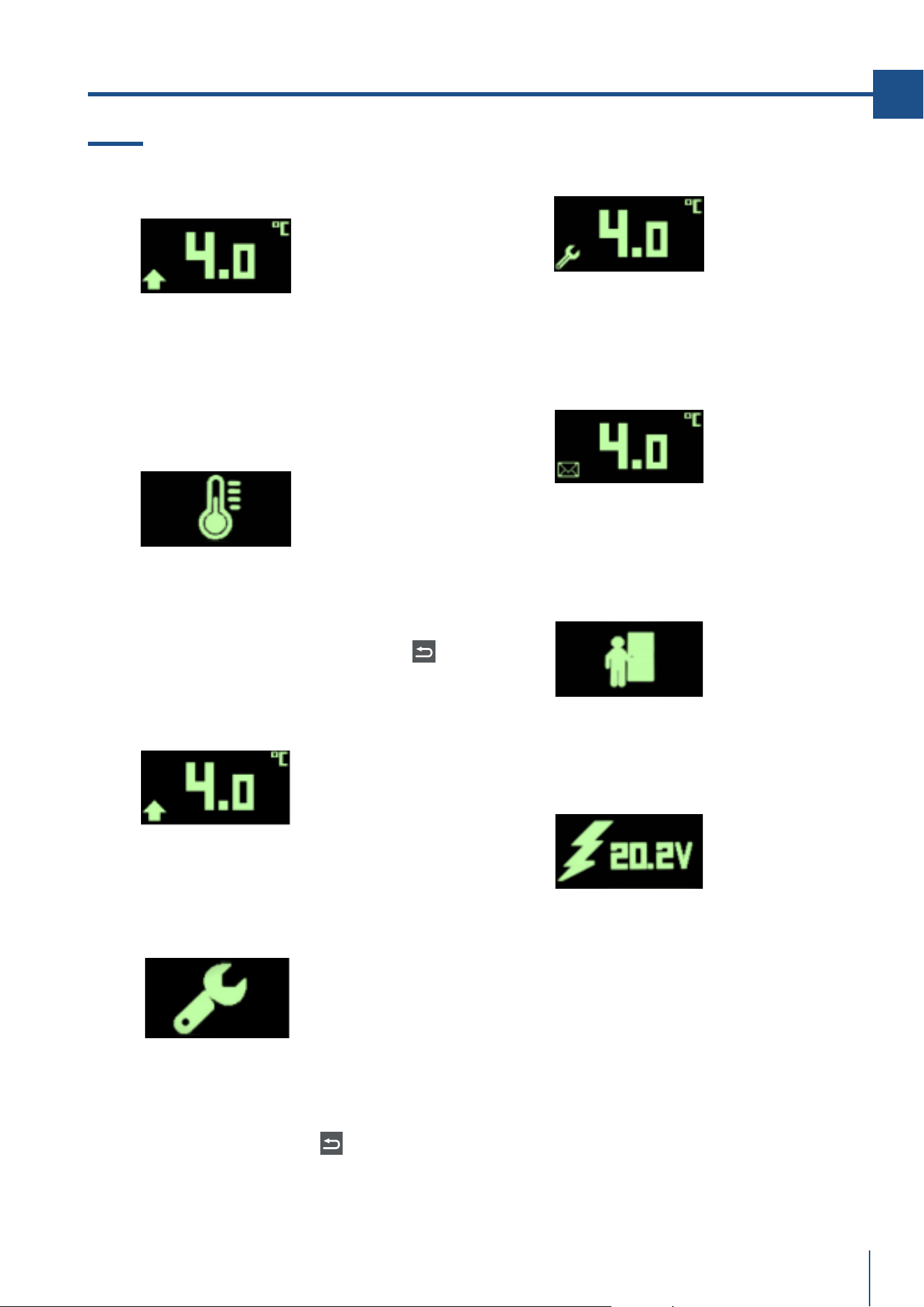
15.1 Notifiche eventi
Stato di preallarme
Quando i limiti di temperatura sono oltrepassati e
non è scaduto il tempo di ritardo allarme il dispo-
sitivo è nello stato di preallarme. Durante lo stato
di preallarme di alta temperatura appare l’icona
FRECCIA ALTA. Durante lo stato di preallarme di
bassa temperatura appare l’icona FRECCIA BASSA.
Rilevamento di allarme
L’insorgere di un allarme di temperatura presenta
l’icona “TERMOMETRO”, attiva il buzzer, il led rosso
lampeggia e la pressione di qualsiasi tasto visualiz-
za la LISTA EVENTI e tacita il buzzer. Si esce dalla
LISTA EVENTI per pressione del tasto BACK
. Il
rientro dell’allarme tacita automaticamente il buz-
zer.
Allarme in corso
Durante lo stato di allarme di alta/bassa tempera-
tura appare a sinistra del frame l’icona “UP/DOWN”
con led rosso lampeggiante. Il rientro dell’allarme
tacita automaticamente il buzzer.
Rilevamento di guasto
L’insorgere di un guasto presenta l’icona “CHIAVE
INGLESE”, attiva il buzzer, il led rosso lampeggia e
la pressione di qualsiasi tasto visualizza la LISTA
EVENTI e tacita il buzzer. Si esce dalla LISTA EVEN-
TI per pressione del tasto BACK
.
Il rientro dell’allarme tacita automaticamente il
buzzer.
15. NOTIFICHE EVENTI
Guasto in corso
Durante lo stato di guasto appare a sinistra del fra-
me l’icona “CHIAVE INGLESE” con led rosso lam-
peggiante e buzzer attivo. Il rientro del guasto tacita
automaticamente il buzzer.
Notifica di evento rientrato
Nel caso in cui un allarme di temperatura o gua-
sto rientrino prima della consultazione della LISTA
EVENTI compare l’icona “BUSTA” a sinistra del fra-
me.
Avviso di porta aperta
In caso di porta aperta, dopo un tempo di ritardo
predefinito, il display visualizza l’icona a lato e viene
attivato il buzzer.
Avviso di tensione fuori range
Il WARNING di tensione di alimentazione occupa
l’intero frame con un icona dedicata. La pressione
di un qualsiasi tasto, o trascorso il tempo in minuti
definito dal parametro BUF, tacita il buzzer. Nel caso
in cui l’evento non si sia risolto ricomparirà dopo 24
ore.
36
www.fhiaba.com · [email protected] · Info Line 800-344222
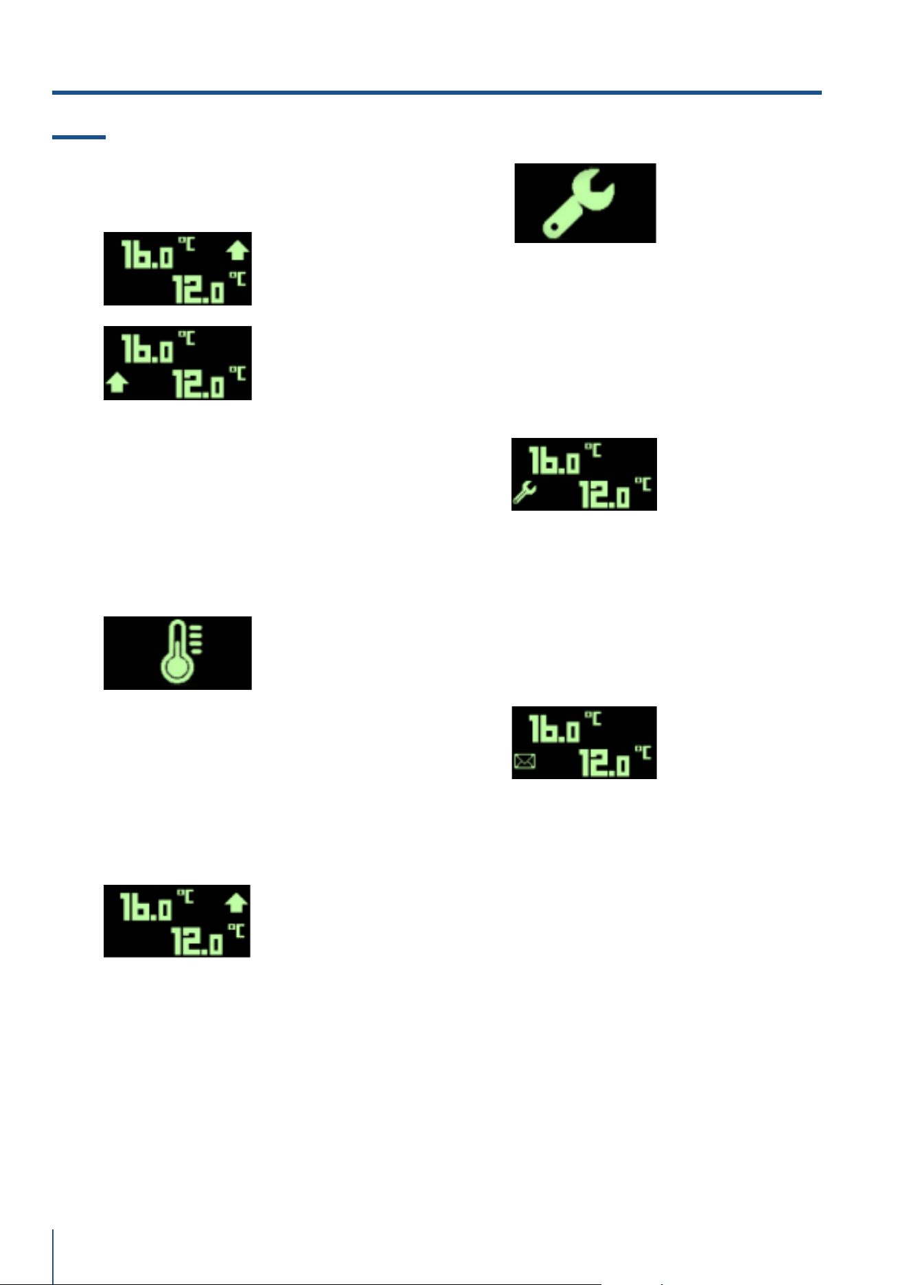
15.2 Notifiche eventi cantina vini e
beverage
Stato di preallarme
Preallarme
nella zona alta
Preallarme
nella zona bassa
Quando i limiti di temperatura sono oltrepassati e
non è scaduto il tempo di ritardo allarme il dispo-
sitivo è nello stato di preallarme in uno o entrambi
i vani. Durante lo stato di preallarme di alta tem-
peratura appare l’icona FRECCIA ALTA a lato del
setpoint di vano. Durante lo stato di preallarme di
bassa temperatura appare l’icona FRECCIA BASSA
a lato del setpoint di vano.
Rilevamento di allarme
L’insorgere di un allarme di temperatura in uno o
entrambi i vani presenta l’icona “TERMOMETRO”,
attiva il buzzer, il led rosso lampeggia e la pressio-
ne del tasto INFO visualizza la LISTA EVENTI e tacita
il buzzer. Si esce dalla LISTA EVENTI per pressione
del tasto BACK. Il rientro dell’allarme tacita auto-
maticamente il buzzer.
Allarme in corso
Durante lo stato di allarme di alta/bassa tempera-
tura appare l’icona “UP/DOWN” a lato del setpoint
di vano con led rosso lampeggiante e buzzer attivo.
La pressione del tasto INFO porta direttamente alla
LISTA EVENTI e tacita il buzzer. Il rientro dell’allar-
me tacita automaticamente il buzzer.
Rilevamento di guasto
L’insorgere di un guasto presenta l’icona “CHIAVE
INGLESE”, attiva il buzzer, il led rosso lampeggia
e la pressione del tasto INFO visualizza la LISTA
EVENTI e tacita il buzzer. Si esce dalla LISTA EVEN-
TI per pressione del tasto BACK.
Il rientro dell’allarme tacita automaticamente il
buzzer.
Guasto in corso
Durante lo stato di guasto di uno o entrambi i vani
appare a sinistra del frame l’icona “CHIAVE INGLE-
SE” con led rosso lampeggiante e buzzer attivo. La
pressione del tasto INFO porta direttamente alla LI-
STA EVENTI e tacita il buzzer.
Il rientro del guasto tacita automaticamente il buz-
zer.
Notifica di evento rientrato
Nel caso in cui un allarme di temperatura o gua-
sto rientrino prima della consultazione della LISTA
EVENTI compare l’icona “BUSTA” a sinistra del fra-
me.
15. NOTIFICHE EVENTI
www.fhiaba.com · [email protected] · Info Line 800-344222
37
www.fhiaba.com · [email protected] · Info Line 800-344222
IT
16. IMPOSTAZIONI E FUNZIONI SPECIALI
16.1 Funzioni speciali
Chill and serve
Chill and Serve attivo
Chill and Serve
attivo zona 1
Chill and Serve
attivo zona 2
Chill and Serve attivo
in entrambi i vani
Forza il setpoint del vano interessato a 4 gra-
di per un’ora (solo Wine Cellar, anche a singolo
vano). Viene attivato/disattivato premendo con-
temporaneamente:
> Tasti CONFERMA
+ UP’ per per Wine Cellar
a singolo vano oppure vano 1 Wine Cellar doppio
vano.
> Tasti CONFERMA
+ DW’ per per vano 2 Wine
Cellar doppio vano
L’attivazione viene confermata dal suono del buz-
zer e l’apparizione dell’iconcina del fiocco di neve
Sabbath mode
Viene attivato/disattivato premendo contempo-
raneamente i tasti CONFERMA
+ BACK
.
> La termostatazione viene effettuata in base ai
tempi parametrici definiti dal costruttore
> Le ventole vengono accese in parallelo al com-
pressore
> Le ventole evaporatore non vengono inibite a
porta aperta
> Gli sbrinamenti sono inibiti
> Tutti gli allarmi sono disabilitati
> Uscite luce sempre spente
> Il display rimane spento
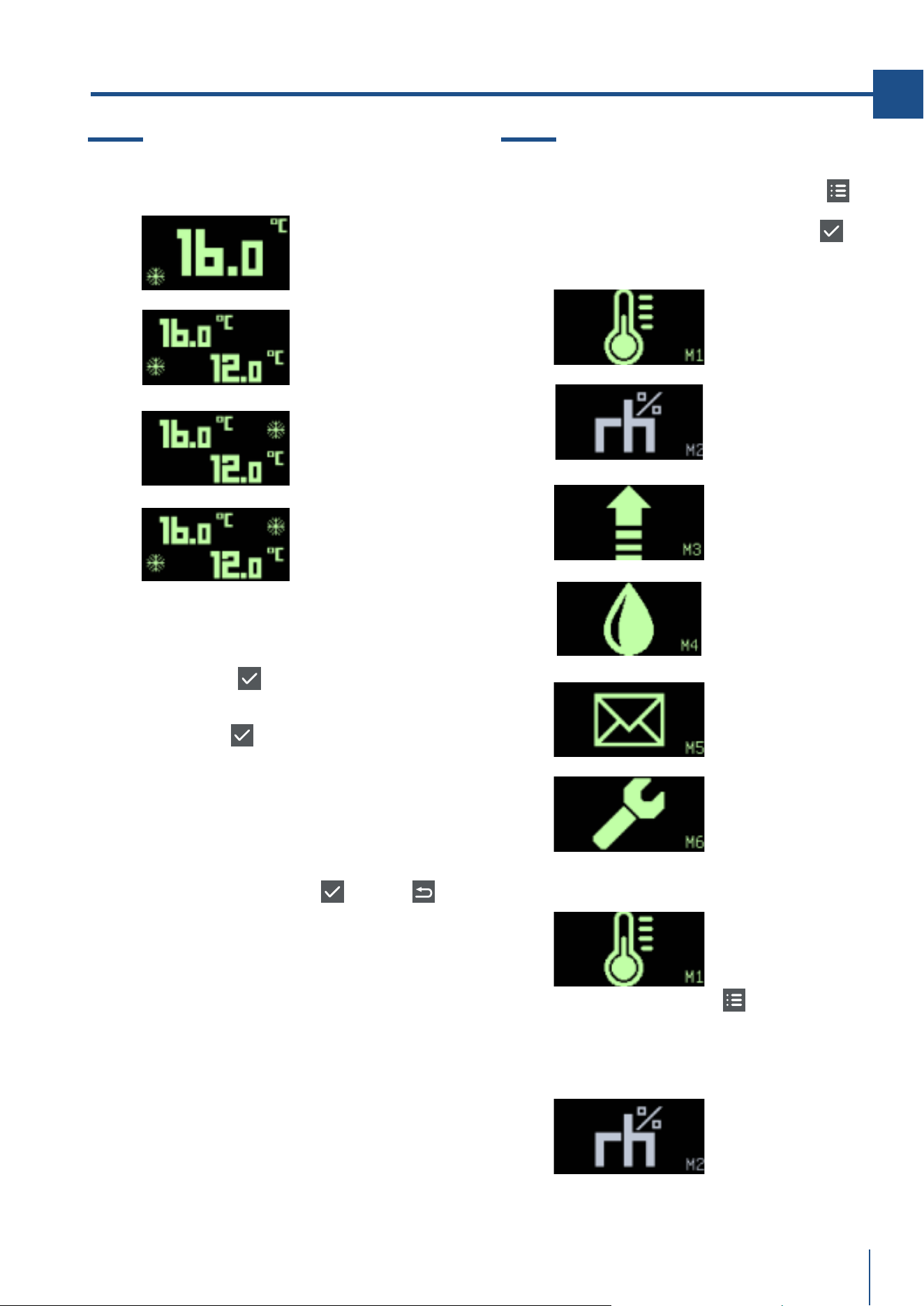
16.2 Menu utente
Si accede per pressione del tasto MENU .; i
menu si selezionano tramite i tasti UP/DW e si
entra per pressione del tasto CONFERMA
. In
basso a destra del display è riportato l’indice di
menu da M1 a M6.
Imposta setpoint
Imposta set umidita’
Imposta limiti di
allarme
Avvia uno
sbrinamento
Lista degli eventi
Menu service
Impostazione del setpoint
La pressione del tasto MENU
, con il frame M1
selezionato, accede all’impostazione del set di
temperatura. Vedi capitolo 3.0
Impostazione del set di umidita
’
Funzione non abilitata
38
www.fhiaba.com · [email protected] · Info Line 800-344222
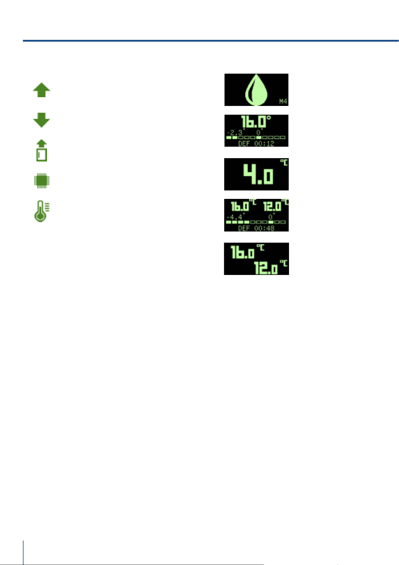
Avvio di uno sbrinamento
Singolo vano
Home Page
Wine Cellar
doppio vano
Home Page
La pressione del tasto CONFERMA, con il frame
M4 selezionato, avvia uno sbrinamento solo se
esistono le condizioni per poterlo effettuare. Di-
versamente restituisce il frame X di negazione.
FASE DI ATTESA
L’avvio dello sbrinamento può contemplare una
fase di attesa nella quale il timer 00:00 non incre-
menta il tempo fino all’avvio.
FASE ATTIVA
Durante lo sbrinamento la barra si popola da si-
nistra verso destra e il timer inizia il conteggio. Il
valore al centro del frame indica la temperatura
di vano e quello a sx la temperatura di evapora-
tore.
INTERRUZIONE
Lo sbrinamento può essere interrotto per pres-
sione del tasto MENU nelle fasi di attesa e di
esecuzione ma non in gocciolamento. Al termine
dello sbrinamento il display si riporta alla home
page. Se è previsto un tempo di gocciolamento
comparirà l’icona goccia terminato il quale si ri-
porterà alla Home Page.
DEFROST AUTOMATICO
Se lo sbrinamento è avviato automaticamente dal
controllore non compare la finestra di DEFROST
ma rimane in Home Page presentando l’icona di
azione sbrinamento.
Icone eventi
Alta temperatura
Bassa temperatura
Alta temp per porta aperta
Alta temperatura
Scheda
Guasto
Sonda
16. IMPOSTAZIONI E FUNZIONI SPECIALI
www.fhiaba.com · [email protected] · Info Line 800-344222
39
www.fhiaba.com · [email protected] · Info Line 800-344222
IT
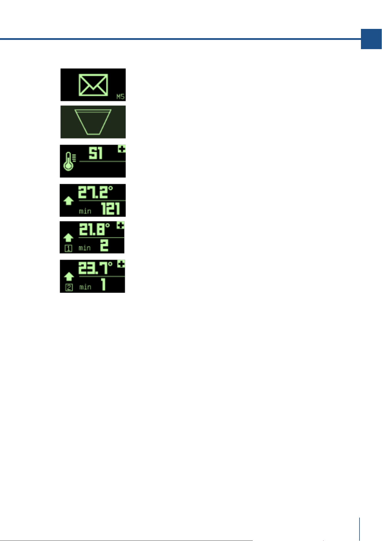
Lista eventi
La pressione del tasto CONFERMA, con il frame
M5 selezionato, presenta la LISTA EVENTI. Nel
caso la lista sia vuota compare per 3 secondi
l’icona cestino vuoto ed il display ritorna nella
Home Page; Nel caso in cui la Lista contenga degli
eventi il simbolo + indica che sono stati registrati
altri eventi che si scorrono tramite il tasto UP.
In caso di spegnimento dell’pannello display ven-
gono cancellati gli eventi registrati in quanto il
dispositivo non contempla un orologio interno.
STRUTTURA DEL RECORD DI GUASTO
Icona rappresentativa – Riferimento del guasto
Nel frame a lato un esempio di guasto sonda ter-
mostato S1
STRUTTURA DEL RECORD DI ALLARME
Icona rappresentativa – Picco – Durata in minuti
Nel frame a lato è rappresentato un allarme di
alta temperatura
STRUTTURA DEL RECORD DI ALLARME PER
WINE CELLAR
Icona rappresentativa - Indice di vano – Picco –
Durata in minuti
Nel frame a lato è rappresentato un allarme di
alta temperatura vano1
e un allarme di temperatura vano 2.

40
www.fhiaba.com · [email protected] · Info Line 800-344222
17.1 Illuminazione
Il beverage center è illuminato con led luce bian-
ca.
I Wine Cellar sono illuminati con barra led luce
ambra e bianca. Luce ambra per illuminare du-
rante l’invecchiamento dei vini e luce bianca per
illuminare durante l’apertura porta.
I cassettoni TriMode sono illuminati con led luce
bianca.
In caso di anomalie e/o guasti del sistema di illu-
minazione è necessario rivolgersi esclusivamen-
te al servizio di assistenza tecnica Fhiaba.
18.1 Indicazioni generali
Il vostro Fhiaba è progettato per assicurare tem-
perature costanti ed appropriati livelli di umidità
in tutti gli scomparti.
Tuttavia, per conservare bene tutti i vostri ali-
menti, non basta avere un ottimo frigorifero, è
anche necessario conoscere le regole per la cor-
retta conservazione del cibo.
Va tenuto presente che tutti gli alimenti inevita-
bilmente modificano le loro caratteristiche con
il passare del tempo. Il loro cambiamento inizia
molto tempo prima del consumo, in quanto essi
contengono, al loro interno, dei microrganismi
che moltiplicandosi ne causano il deterioramen-
to.
Questo è reso più rapido da manipolazioni, tem-
perature di conservazione e condizioni di umidità
inappropriate.
Vi raccomandiamo, quindi, di seguire le indica-
zioni di seguito riportate che vi consentiranno di
utilizzare nel modo più razionale e sicuro il vo-
stro frigorifero-congelatore e conservare a lungo
e nel miglior modo possibile tutti i vostri alimenti.
Accertatevi periodicamente che tutti gli alimenti
siano in perfetto stato di conservazione. È spesso
abbastanza chiaro quando un alimento è dete-
riorato, in quanto ammuffisce, prende un cattivo
odore ed assume un aspetto sgradevole.
Tuttavia vi sono dei casi in cui tale condizione non
è così evidente.
Se pensate che un alimento sia stato conservato
troppo a lungo e che quindi possa essere avaria-
to, non consumatelo e nemmeno assaggiatelo per
il controllo, anche se vi sembra ancora buono, in
quanto i batteri che provocano il deterioramento
del cibo possono essere la causa di intossicazioni
o di malesseri. Nel dubbio gettate via l’alimento.
17. ILLUMINAZIONE 18. INDICAZIONI GENERALI
www.fhiaba.com · [email protected] · Info Line 800-344222
41
www.fhiaba.com · [email protected] · Info Line 800-344222
IT
19. CURA E PULIZIA
19.1 Cura e pulizia
Per la pulizia delle parti in acciaio usare il panno
in microfibra e l’apposita spugnetta che si trova-
no nel kit fornito in dotazione con l’apparecchia-
tura.
> Nel passare il panno e la spugnetta seguire
sempre il verso della satinatura dell’acciaio.
> Di tanto in tanto, per ripristinare la lucentezza
dell’acciaio, passare il panno in microfibra leg-
germente inumidito.
> In particolare vanno mantenute libere da ostru-
zioni le aperture di ventilazione dell’apparecchia-
tura interne ed esterne.
Nota
Seguite scrupolosamente le istruzioni
dettagliate che si trovano nel kit in
dotazione e in nessun caso utilizzare
prodotti abrasivi o metallici perché
potrebbero rigare e danneggiare in
modo permanente la finitura satinata
dell’apparecchiatura. Prima di eseguire
qualsiasi operazione di pulizia
disconnettere l’apparecchio dalla
rete elettrica.Porre attenzione a non
danneggiare in qualsiasi modo il circuito
refrigerante.
19.2 Pulizia griglia di ventilazione, fil-
tro e condensatore
Per la pulizia usare un aspirapolvere con spazzo-
la morbida al massimo della potenza aspirante,
passandolo sulle feritoie della griglia.
Nel caso di un significativo accumulo di polvere,
la griglia di ventilazione può essere rimossa per
consentire una pulizia più approfondita del con-
densatore.
19.3 Pulizia interna
> Pulire le parti interne e le parti asportabili la-
vandole con una soluzione di acqua tiepida, po-
chissimo detersivo per piatti.
> Risciacquate ed asciugate subito.
> Si raccomanda di non usare dispositivi mec-
canici o altri mezzi per accelerare il processo di
sbrinamento.
Nota
Non mettete a contatto con l’acqua bollente
le parti fredde in vetro. Non lavate nessun
particolare del frigorifero in lavastoviglie
in quanto potrebbe danneggiarsi o
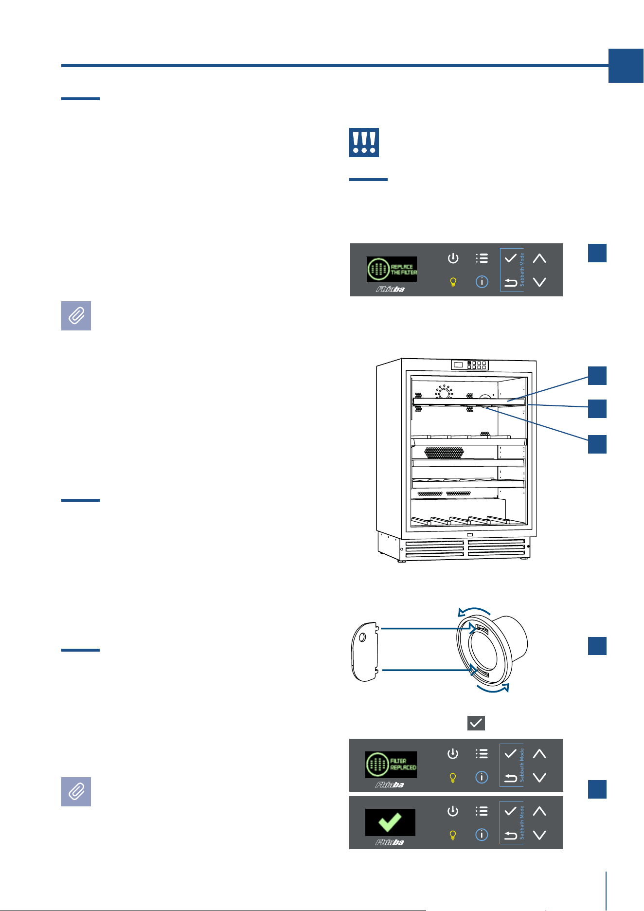
> Compare la richiesta del cambio del filtro sul
display [ 1 ], sostituire il filtro.
> Rimuovere il ripiano in legno superiore [ 2 ] e
togliere la sua guida laterale [ 3 ].
In fondo si trova il filtro [ 4 ].
> Inserire l’apposita chiavetta, ruotare, estrarre
il vecchio filtro e sostituirlo con quello nuovo.
Poi reinserire la guida laterale e il ripiano [ 5 ].
> Resettare il messaggio di aviso sul display
tenendo premuto OK
( ) [ 6 ].
deformarsi irreparabilmente.
Attenzione
Non usare acqua sulle parti elettriche,
sulle luci e sui pannelli di controllo.
19.4 Sostituzione filtro carboni attivi.
1
2
3
4
5
6

42
www.fhiaba.com · [email protected] · Info Line 800-344222
1
1.1
1.2
1.3
1.4
IMPORTANT DIRECTIONS FOR SAFETY AND THE ENVIRONMENT
For your safety
Important information when using the appliance
Caring for the environment
Cleaning, sanitisation and maintenance of the ice and/or water dispenser (if present)
42
42
42
43
43
2
2.1
2.2
2.3
2.4
INSTALLATION
Installation
Connection to the water system (if present)
Connection to the electrical power supply
Refrigerant
43
43
43
44
44
3
3.1
3.2
BEFORE STARTING
Know your Fhiaba
Child safety
44
44
45
4
4.1
4.2
4.3
4.4
TECHNICAL REQUIREMENTS
Installation Opening Requirements: Beverage and Wine Cellar Indoor
Installation Opening Requirements: TriMode drawers Indoor
Installation Opening Requirements: Beverage and Wine Cellar Outdoor
Installation Opening Requirements: TriMode drawers Outdoor
46
46
47
48
49
5
5.1
5.2
5.3
PREPARING THE INSTALLATION
Transport to installation site and unpacking
Electrical and Water connection
Anti-Tip Bracket
50
50
50
51
6
6.1
6.2
DOOR SWING
Change the opening direction of the door (Indoor models)
Change the opening direction of the door (Outdoor models)
52
52
53
7
7.1
7.2
7.3
7.4
7.5
PANEL MOUNTING
Integrated Panel Dimensions
Mounting the handles
Integrated Panel Installation
Mounting panel to the door
Mounting panels to the drawers
54
54
56
57
58
60
8
8.1
VENTILATION
Ventilation
61
61
9
9.1
DOOR SWING
Door swing
62
62
10
10.1
POST INSTALLATION
Post installation checklist
62
61
11
11.1
FEATURES
Main components
63
63
12
12.1
12.2
12.3
12.4
GETTING STARTED
Main control panel
Layout
Functions
Keypad
64
64
65
65
65
13
13.1
SWITCHING ON/OFF
Switching ON/OFF
66
66
14
14.1
ADJUSTMENTS
How to adjust the temperature to meet user requirements
66
66
INDEX

43
www.fhiaba.com · [email protected] · Info Line 800-344222
EN
15
15.1
15.2
EVENT NOTIFICATIONS
Event notifications
Wine cellar event notifications
67
67
68
16
16.1
16.2
SETTINGS AND SPECIAL FUNCTIONS
Special functions
User menus
69
69
69
17
17.1
LIGHTING
Lighting
72
72
18
18.1
GENERAL DIRECTIONS
General directions
72
72
19
19.1
19.2
19.3
CARE AND CLEANING
Care and Cleaning
Condenser cleaning
Internal cleaning
73
73
73
73

44
www.fhiaba.com · [email protected] · Info Line 800-344222
1. IMPORTANT DIRECTIONS FOR SAFETY AND THE ENVIRONMENT
1.1 For your safety
> If this appliance is replacing an existing appliance
which must be removed or disposed of, make sure
that it does not become a dangerous trap for chil-
dren by cutting its power supply cable and render-
ing it impossible to close the door. Use the same
caution at the end of the lifespan of the new appli-
ance.
> The appliance is not designed to operate with ex-
ternal timers or with remote-control systems.
> This appliance is designed to refrigerate bever-
ages and foods and is intended for domestic use.
> This appliance is for refrigeration and conserva-
tion of fresh and frozen foods in the home. Every
other use is considered inappropriate.
> The appliance must be installed by following
the instructions in the Installation Guide, particu-
lar care should be taken not to obstruct the vent
openings of the appliance and of the built-in units.
> The appliance features a concentrated lighting
system with LED lamps. Do not stare into these
lamps when they are on to avoid possible eyesight
damage.
This warning is also contained on the label attached
to the inside of the refrigerator door.
> When the freezer is functioning do not touch the
inner surfaces in stainless steel with wet or damp
hands, since skin may stick to the very cold sur-
faces.
> Do not use any type of electrical equipment inside
of the food conservation compartments.
> When positioning the shelves, do not place fingers
in the shelf slide guides.
> Do not place flammable liquid containers nearby
the equipment.
> Never attempt to extinguish a flame/fire with wa-
ter: turn o the appliance and cover the flame with
a fireproof blanket.
> Do not position containers of flammable liquids
near the appliance.
> Completely switch o the appliance and unplug
the power supply cable during cleaning operations.
If the plug is not easily reached, it is a good idea to
turn o the breaker or remove the fuse that con-
trols the socket that the appliance is connected to.
> The packaging parts can be dangerous for chil-
dren: do not allow children to play with the plastic
bags, plastic film or Styrofoam.
> Any repairs must be performed by a qualified Fh-
iaba Service technician.
> This appliance is not intended for use by persons
(including children) with reduced physical, sensory
or lack of experience and knowledge unless they
have been given supervision or instruction con-
cerning use of the appliance by a person responsi-
ble for their safety. Children should be supervised
to ensure that they do not play with the appliance.
> Do not damage the appliance refrigerant circuit
pipes.
> Do not store explosive substances such as aerosol
cans with a flammable propellant in this appliance.
> If the power cord of this appliance is damaged,
it must be replaced by the manufacturer, customer
service or a similarly qualified person. Improper in-
stallations and repairs may put the user at consid-
erable risk.
> Repairs may be performed by the manufacturer,
customer service or a similarly qualified person
only.
> Plug into a grounded 3 prong outlet.
> Do not remove ground prong.
> Do not use an adapter.
> Do not use an extension cord.
> Disconnect power to all units before servicing.
> If the SUPPLY CORD is damaged, it must be repla-
ced by the manufacturer, its service agent or simi-
lar qualified person in order to avoid a hazard.
> Children should be supervised to ensure that they
do not play with the appliance.
children.
> Do not modify this appliance.
> Do not insert pointed metal objects (cutlery or
utensils) into the slots in the appliance.
> Do not touch (especially with wet hands) frozen
products or 22 - PRECAUTIONS 914779600/A put
them in your mouth directly.
> Do not store inflammable, explosive or volatile
substances.
> Do not keep explosive substances, such as spray
bottles with flammable propellants in the applian-
ce.
> Bottles containing strong alcoholic drinks must
be tightly closed and stored vertically.
> Organic compounds, acids and essential oils can
corrode the seals and plastic surfaces if
left in contact with them for extended periods.
> Turn o the appliance and unplug it from the
mains before cleaning or maintenance.
> Do not pull the cable to unplug the appliance.

45
www.fhiaba.com · [email protected] · Info Line 800-344222
EN
www.fhiaba.com · [email protected] · Info Line 800-344222
1.2 Important information when using
the appliance
> Cleaning and maintenance that should be per-
formed by the user must not be carried out by
unsupervised children.
> Never use electrical appliances inside the appli-
ance (e.g. heater, electric ice maker, etc.). Explosion
hazard!
> Never defrost or clean the appliance with a
steam cleaner! The steam may penetrate electri-
cal parts and cause a short-circuit. Risk of electric
shock!
> Do not use pointed and sharp-edged implements
to remove frost or layers of ice. You could dam-
age the refrigerant tubes. Leaking refrigerant may
cause eye injuries or ignite.
> Take care that no objects are stuck in the doors.
> Do not store products which contain flammable
propellants (e.g. spray cans) or explosive sub-
stances in the appliance.
Explosion hazard!
> Do not stand on or lean heavily against base of
appliance, drawers or doors, etc.
> Before cleaning the appliance, pull out the power
cord plug or switch o the fuse. Do not pull out the
power cord plug by tugging on the power cord.
> Store high-percentage alcohol tightly closed and
standing up.
> Keep plastic parts and the door seal free of oil
and grease. Otherwise, parts and door seal will
become porous.
> Never cover or block the ventilation openings for
the appliance.
injury
> According to current regulations, children betwe-
en 3 and 8 years of age can take or load food from
the appliance, but it is highly discouraged to allow
children under 8 years of age to perform these
operations and in general to use the appliance.
> Keep children under the age of eight at a safe di-
stance unless they are constantly supervised
and make sure that they do not play with the applian-
ce.
> Do not use mechanical, electrical, chemical de-
vices other than those recommended by the manu-
facturer to speed up the defrosting process.
> Do not damage the cooling circuit (if it can be ac-
cessed).
> Do not use electrical appliances inside food stor-
age compartments unless these are of the type
recommended by the manufacturer.
>In the event of damage to the cooling circuit, avoid
the use of naked flames and ventilate the area
properly.
> Do not use the appliance or parts of it in ways
other than those specified in this manual.
> Opening the door for long periods can cause the
temperature in the appliance compartments to rise
considerably.
>Clean surfaces that may comeinto contact with food
and accessible drainage systems regularly.
> Store raw meat and fish in suitable containers in
the refrigerator, so that it does not come into contact
with other food or drip on it.
> If the appliance is left empty for long periods of
time, switch it o, thaw it, clean it, dry it and leave the
door open to prevent the development of mould
inside.
> Never rest sharp metal objects such as knives, for-
ks, spoons and lids on the appliance during use.
> Do not use abrasive or corrosive detergents (e.g.
scouring powders, stain removers and metallic
sponges) on glass parts.
> Do not sit on the appliance.
> Do not sit or lean on the door or any open drawers.
> Do not prize on the door or handle to move the ap-
pliance.
> Do not use electrical appliances (e.g. hair dryers) or
sprays for defrosting, the plastic parts could be da-
maged.
> Do not use the appliance to cool rooms for any re-
ason.
> Always unplug the appliance in the event of a fault
or when performing cleaning or maintenance.
> Do not keep liquids in tins or glass containers in
the freezer.
> Do not place heavy objects on the top of the ap-
pliance.
46
www.fhiaba.com · [email protected] · Info Line 800-344222
Symbols used in the Manual:
Note
tips for correct use of the appliance
Important
Warnings to prevent damage to the
device
Attention
Warnings to prevent injury to persons
1.3 Caring for the environment
> This appliance conforms to the WEEE European di-
rective (2012/19/EU) and must be disposed of sepa-
rately from other waste at the end of its service life.
> The appliance does not contain substances in
quantities sucient to be considered hazardous to
health and the environment, in accordance with cur-
rent European directives.
> Pay special attention to correct disposal proce-
dure for all the packaging materials.
Power voltage
Danger of electrocution
Disconnect the mains power supply.
Unplug the appliance.
> The appliance must not be disposed of with urban
waste. Contact local waste disposal centres for on
how to dispose of recyclable waste.
> To dispose of the appliance: Cut the power cable
and remove it.
> Prior to disposal, cut the power supply cord and
make it impossible to close the door.
> During disposal, avoid damage to the refrigera-
tion circuit.
> The appliance does not contain hazardous sub-
stances for the atmospheric ozone layer, neither in
the refrigeration circuit nor in the insulation.
> Our appliances are packaged in non-polluting
and recyclable materials.
> Deliver the packing materials to the appropriate
recycling centre.
Plastic packaging
Danger of suffocation
Do not leave the packaging or any part
of it unattended.
Do not let children play with the plastic
bags.
1.4 Cleaning, sanitization and mainte-
nance of the ice and/or water dispenser
(if present)
> Any work on the appliance must be carried out
by a qualified technician or authorized After-Sales
Service.
Warning
To avoid contamination of food, please
respect the following instructions:
> Opening the door for long periods can
cause a significant increase of the tempe-
rature in the compartments of the applian-
ce.
> Clean regularly surfaces that can come in
contact with food and accessible drainage
systems.
> Clean water tanks if they have not been
used for 48 h; flush the water system con-
nected to a water supply if water has not
been drawn for 5 days.
> Store raw meat and fish in suitable con-
tainers in the refrigerator, so that it is not in
contact with or drip onto other food.
>Two-star frozen-food compartments are
suitable for storing pre-frozen food, storing
or making icecream and making ice cubes.
> One-, two- and three-star compartments
are not suitable for the freezing of fresh
food.
> If the refrigerating appliance is left empty
for long periods, switch o, defrost, clean,
dry, and leave the door open to prevent
mould developing within the appliance.
1. IMPORTANT DIRECTIONS FOR SAFETY AND THE ENVIRONMENT
47
www.fhiaba.com · [email protected] · Info Line 800-344222
EN
C
C
D
E
B
A
A
G
H
F
PACKAGING MATERIAL KEY
Material Abbreviation Numbering
A
Low-density
polyethylene
LLDP
E4
B
Uncorrugated
cardboard
PA
P2
1
C
Polystyrene
PS 6
D
Wood
FO
R5
0
E
Iron
FE 40
F
Polyvinyl
chloride
PV
C3
G
Polypropylene
terephthalate
PE
T1
H
Corrugated
cardboard
PA
P2
0
1.5 Informations for control bodies
> For EcoDesign checks, the installation and
preparation of the appliance must comply with EN
62552 standard.
> Ventilation requirements, dimensions and
minimum space from the rear wall are indicated in
the “Installation” chapter of this manual.
> Contact the manufacturer for more information.
1.6 To save energy
> Correct use of the appliance, correct
packaging of foodstus, a constant
temperature and food hygiene have eects
on the quality of storage.
> Reduce the number of times that the doors
are opened and the length of time they
remain open to prevent the compartments
from heating up excessively.
> Clean the condenser (if it can be accessed)
at the rear of the appliance periodically to
prevent the appliance from losing eciency.
> Defrost frozen food in the refrigerator
compartment in order to make use of the
cold stored in the frozen foods.
1.7 Environmental labelling
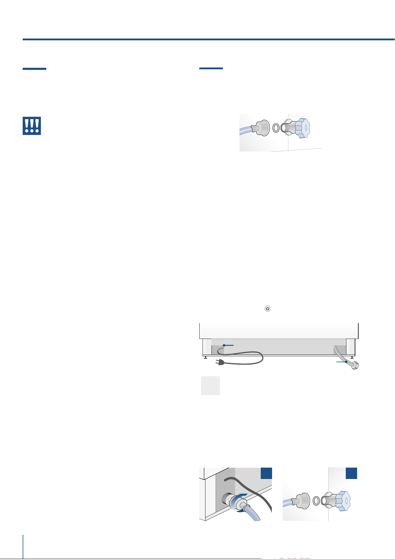
48
www.fhiaba.com · [email protected] · Info Line 800-344222
2.2 Connection to the water system
The models provided with Ice Maker require a con-
nection to the domestic water supply system. This
can be executed only through the provided new wa-
ter hose with 3/4” threading.
The system pressure must be between 0.05 MPa
and 0.5 MPa (between 0.5 bar and 5 bar).
Dierents pressures can cause malfunctions or
leaks in the water system. The appliance should be
supplied only with drinkable water.
Operate as follows:
> Unwind the electric cable and connect it directly to
the wall socket.
> Make sure the appliance is in the Stand-by con-
dition and that all lights are o; should it be not so
press the Unit button
to switch it o.
2.1 Installation
Make sure that installation is performed correctly,
adhering to all directions in the specific installation
manual provided with the appliance.
Warning
Always connect the water before the
power.
The appliance must be connected to ground in
compliance with electrical system safety stand-
ards.
> Position the appliance with the aid of a second
person.
> Never use the open door tolever the appliance into
place when fitting.
> Avoid exerting too much pressure on the door
when open.
> The appliance must not be installed near heat
sources. If this is not possible, suitable insulation
must be used.
>The appliance must not be exposed to direct sun-
light.
> Do not use the appliance outdoors.
> Installation and servicing should be carried out
by qualified personnel in accordance with current
standards.
> Have the electrical connection performed by au-
thorised technical personnel.
> For avoiding dangers, if the power supply cable is
damaged, contact technical support immediately
and they will replace it, so as to prevent any risk.
> Always use any necessary/ required personal
protective equipment (PPE) before performing any
work on the appliance (installation, maintenance,
positioning or movement).
> Before performing any operation on the appli-
ance, switch o the power supply.
> This appliance can be used up to a maximum alti-
tude of 4,000 metres above sea level.
>If installed near another refrigerator or freezer,
keep it at a minimum distance of 2 cm.
>Do not try to repair the appliance yourself or with-
out the assistance of a qualified technician.
>Do not install/use the appliance outdoors.
>CAUTION: while positioning the appliance, make
sure that the power supply cable is not caught or
damaged.
>To prevent instability of the appliance, install and
secure it correctly as indicated in the instructions
provided in this manual.
> Fit one end of the water hose onto the connector at
the appliance’s back, using the supplied 3/4” fitting
[ 1 ] .
> Fit the other end of the hose to the water tap, using
the supplied 3/4” fitting [ 2 ].
> On freezer models only, install the water filter sup-
port outside the appliance, using the fittings supplied
1 2
Back of appliance
Electrical connection
Water connection
2. INSTALLATION
49
www.fhiaba.com · [email protected] · Info Line 800-344222
EN
2.4 Refrigerant
The refrigerant isobutane (R600a) is contained with-
in the refrigerant circuit of the appliance, a natural
gas with a high level of environmental compatibility,
which is nevertheless flammable.
> During transportation and installation of the ap-
pliance, be certain that none of the components of
the refrigerant circuit become damaged.
> If the refrigerant circuit should become damaged:
– avoid open flames and sources of ignition;
– thoroughly ventilate the room in which the appli-
ance is situated.
ISO 7010 W021
2.3 Connection to the electrical power
supply
The appliance is equipped with a Schuko type 16A
plug and must be connected to the electrical power
supply through a corresponding Schuko socket.
Do not use extension cords and/or multiple adapt-
ers for the power supply connection
Important
Do not use extension cords and/or mul-
tiple adapters for the power supply con-
nection.
Warning
If energy is supplied through an alter-
native energy power source (solar, geo-
thermal, etc..) or if home automation
systems are installed, it is necessary to
install the Alternative Energy Kit to inte-
grate the unit into the power grid.
Caution:
risk of fire / flammable materials.
Important
Carry out transportation, installation
and/or clearing with extra care so that
no damage occours to the refrigeration
circuit.
Warning
The appliance should be supplied only
with drinkable water.
Warning
Make sure that installation is performed
correctly, according to all of the direc-
tions in the specific installation manual
provided with the appliance.
Warning
Do not attempt to use a locally sourced
garden hose threaded adapter or braid-
ed supply line. It will strip the threads on
the appliance water connection solenoid.

50
www.fhiaba.com · [email protected] · Info Line 800-344222
3. BEFORE STARTING
3.1 Know your Fhiaba
Congratulations for having purchased your new Fh-
iaba: from now on you can use our innovative con-
servation system, which will allow you to keep all of
your food in the best way possible.
This manual will answer most of your questions
about the product’s features. Should you require
further information, please.
3.2 Manufacturer’s liability
The manufacturer declines all liability for
damage to persons or property caused by:
> use of the appliance other than that
specified;
> failure to comply with the instructions in the
user manual;
> tampering with any part of the appliance;
> use of non-original spare parts.
3.3 Technical support
> In the event of failure of the appliance, contact the
technical support and have the repair carried out by
qualified personnel only.
> make sure you have the model and serial number
available on the identification plate.
> Use original spare parts only.
>Do not try to repair the appliance yourself or
without the assistance of a qualified technician: this
aects safety and may void the warranty.
> Original spare parts remain available for 10 years
after the last production of the model.
> The following spare parts are available only for
authorized repair technicians: electronic boards,
thermostats, temperature sensors, hinges, lamps,
door handles.
> Our green number
800-344222 (800-FHIABA)
> call us: +39 0434 420160
> write us an e-mail at car[email protected]
> check our website www.fhiaba.com
Important
Before calling take note of the serial
number of the appliance, shown on the
warranty certificate and on the serial
number plate located inside the refrig-
erator compartment on the side opposite
the door opening.
3.4 Technical data
Refrigerant type, storage volume and other tech-
nical data can to be found on the product plate.
Further information on all available models can
be found at https://www.fhiaba.com/energy-
label website (Europe only). This link refers to
the official page of the European EPREL prod-
uct database, the address of which has not been
published at the time of printing. Follow the
guidelines to find the relevant model. Models
can be identified according to the sign placed
before the product code bar (E-Nr.) on the prod-
uct plate. The model can also be found in the
first line of the Energy Label.
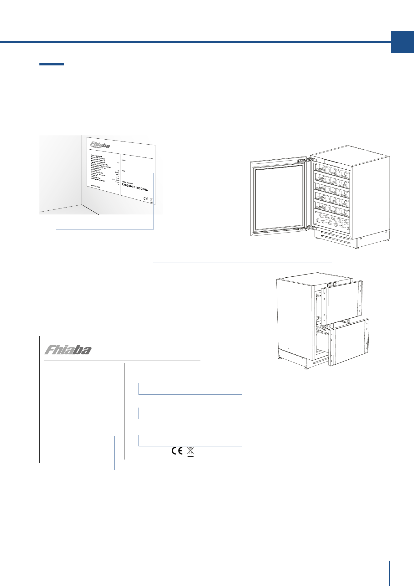
51
www.fhiaba.com · [email protected] · Info Line 800-344222
EN
www.fhiaba.com · [email protected] · Info Line 800-344222
UCB602TP
Serial Number .
Conservation Tips
> SN (Subnormal) from + 10°C to + 32°C
> N (Normal) from + 16°C to + 32°C
> ST (Subtropical) from + 18°C to + 38°C
> T (Tropical) from + 18°C to + 43°C
Gross capacity (l)
Net capacity Fridge (l)
Net capacity Fresco (l)
Net capacity Freezer(l)
Freezing Capacity (kg/12h)
Refrigerant Fridge/Fresco (gr)
Refrigerant Freezer (gr) 30,0
Refrigerant Type
Climatic Class
Defrost Heater (W)
Total Absorbed Current (A)
Voltage (V~)
Frequenzy (Hz)
Lighting Neon/Led (W)
Temperature Rise Time
MADE IN ITALY
143
R600a
SN/T
30
1.5
220-240 V
50-60 Hz
0
MODEL
TYPE
SERIAL NUMBER
UCB602TP
F20230507000016
Position of the serial number inside the compartment.
Model .
Features .
Type .
3.5 Product plate
The product plate shows the technical data, the
serial number and the model. The product plate
must never be removed.
The product plate is positioned inside the
equipment in the lower left corner.
The product plate is positioned on the
outside of the upper drawer on the left.
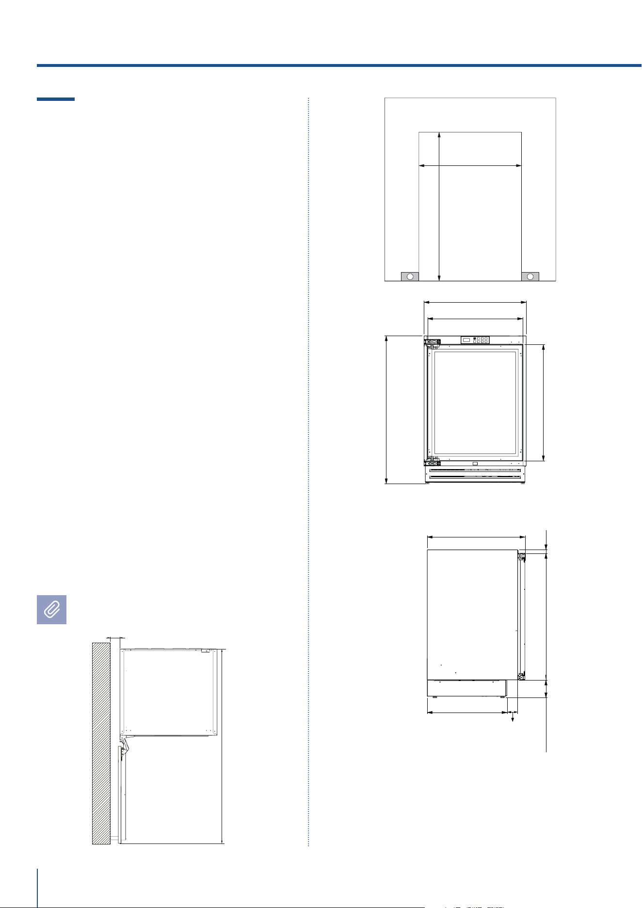
60 (2 23/64”)
1193 (46 31/32”)
UCW602TP: 600 (23 5/8”)
873 Min - 900 Max
(34 3/8” Min - 35 7/16” Max)
865 Min - 890 Max
(34 3/64” Min - 35 1/32” Max)
104 Min - 129 Max
(4 3/32” Min - 5 5/64” Max)
598 (23 35/64”)
556 (21 7/8”)
680 (26 49/64”)
468 (18 27/64”)
572 (22 33/63”)
21 (53/64”)740 (29 9/64”)
EE
UCB601TP: 600 (23 5/8”)
UCB602TP: 600 (23 5/8”)
UCW601TP: 600 (23 5/8”)
63 (2 31/64”)
52
www.fhiaba.com · [email protected] · Info Line 800-344222
4.1 Installation Opening
Requirements: Beverage and Wine
Cellar Premium Indoor
- Fully integrated / panel ready
E - area to be left clear for the power supply cable
Opening Height
Min 873 mm - Max 900 mm
(Min 34 3/8” - Max 35 7/16”)
Minimum Opening Width
UCB601TP: 600 mm (23 5/8”)
UCB602TP: 600 mm (23 5/8”)
UCW601TP: 600 mm (23 5/8”)
UCW602TP: 600 mm (23 5/8”)
Minimum Opening Depth
600 mm (23 5/8”)
Door Swing Clearance
1193 mm (46 31/32”)
Door Opening Angle
115° / 90° optional
Width
598 mm (23 35/64”)
Height
Min 865 mm - Max 890 mm
(Min 34 3/64” - Max 35 1/32”)
Depth with door (without panel)
572 mm (22 33/63”)
Dimensions in parentheses
are in inches.
4. TECHNICAL REQUIREMENTS
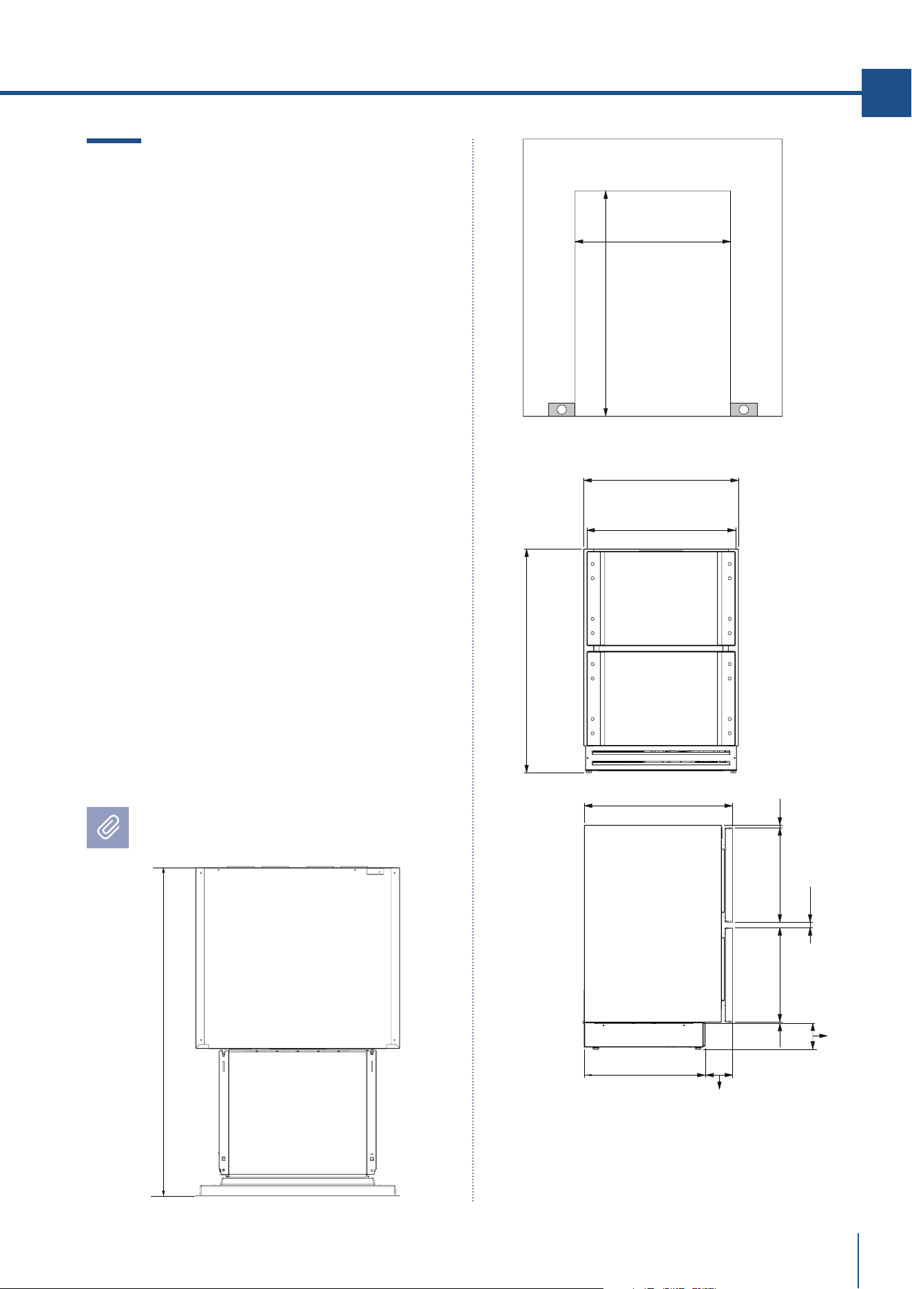
961 (37 53/64”)
UC2D60P: 600 (23 5/8”)
UC2D75P: 750 (29 17/32”)
UC2D90P: 900 (35 7/16”)
UC2D60P: 598 (23 35/64”)
UC2D75P: 748 (29 29/64”)
UC2D90P: 898 (35 23/64”)
UC2D60P: 574 (22 39/64”)
UC2D75P: 724 (28 1/2”)
UC2D90P: 874 (34 13/32”)
468 (18 27/64”)
63 (2 31/64”)
572 (22 33/63”)
13 (33/64”)
4 (5/32”)
20 (25/32”)
362 (14 1/4”)362 (14 1/4”)
E E
873 Min - 900 Max
(34 3/8” Min - 35 7/16” Max)
865 Min - 890 Max
(34 3/64” Min - 35 1/32” Max)
104 Min - 129 Max
(4 3/32” Min - 5 5/64” Max)
53
www.fhiaba.com · [email protected] · Info Line 800-344222
EN
www.fhiaba.com · [email protected] · Info Line 800-344222
4.2 Installation Opening
Requirements: TriMode drawers
Premium Indoor
- Fully integrated / panel ready
E - area to be left clear for the power supply cable
Opening Height
Min 873 mm - Max 900 mm
(Min 34 3/8” - Max 35 7/16”)
Minimum Opening Width
UC2D60P: 600 mm (23 5/8”)
UC2D75P: 750 mm (29 17/32”)
UC2D90P: 900 mm (35 7/16”)
Minimum Opening Depth
600 mm (23 5/8”)
Drawer Swing Clearance
961 mm (37 53/64”)
Width
UC2D60P: 598 mm (23 35/64”)
UC2D75P: 748 mm (29 29/64”)
UC2D90P: 898 mm (35 23/64”)
Height
Min 865 mm - Max 890 mm
(Min 34 3/64” - Max 35 1/32”)
Depth with door (without panel)
572 mm (22 33/63”)
Dimensions in parentheses
are in inches.
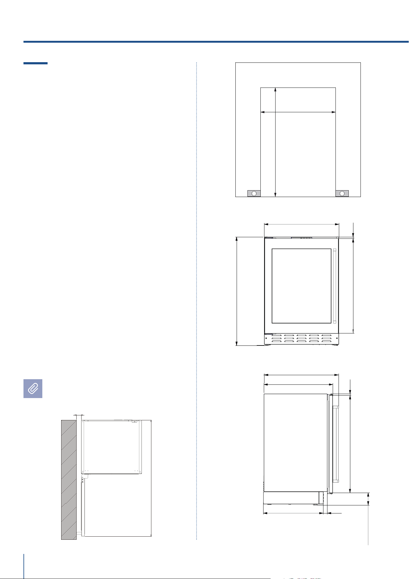
48 (1 57/64”)
1148 (45 13/64”)
UCW602TPO: 600 (23 5/8”)
873 Min - 900 Max
(34 3/8” Min - 35 7/16” Max)
865 Min - 890 Max
(34 3/64” Min - 35 1/32” Max)
598 (23 35/64”)
499 (19 41/64”)
576 (22 43/64”)
625,4 (24 5/8”)
EE
758,5 (29 55/64”)
12 (15/32”)
12 (15/32”)
32,4 (1 9/32”)
758,5 (29 55/64”)
94,5 Min - 119,5 Max
(37 13/64” Min - 47 3/64” Max)
UCB601TPO: 600 (23 5/8”)
UCB602TPO: 600 (23 5/8”)
UCW601TPO: 600 (23 5/8”)
54
www.fhiaba.com · [email protected] · Info Line 800-344222
4.3 Installation Opening
Requirements: Beverage and Wine
Cellar Premium Outdoor
- Built-in with front and handles, in stainless steel
E - area to be left clear for the power supply cable
Opening Height
Min 873 mm - Max 900 mm
(Min 34 3/8” - Max 35 7/16”)
Minimum Opening Width
UCB601TPO: 600 mm (23 5/8”)
UCB602TPO: 600 mm (23 5/8”)
UCW601TPO: 600 mm (23 5/8”)
UCW602TPO: 600 mm (23 5/8”)
Minimum Opening Depth
600 mm (23 5/8”)
Door Swing Clearance
1148 mm (45 13/64”)
Door Opening Angle
115°
Width
598 mm (23 35/64”)
Height
Min 865 mm - Max 890 mm
(Min 34 3/64” - Max 35 1/32”)
Depth with door
576 mm (22 43/64”)
Dimensions in parentheses
are in inches.
4. TECHNICAL REQUIREMENTS
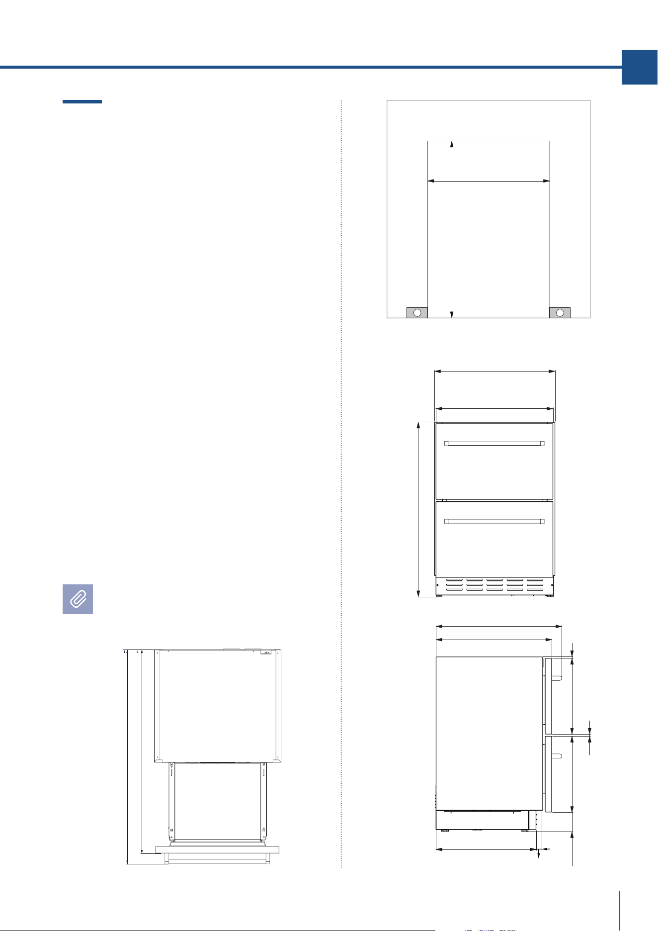
958 (37 23/32”)
1008 (39 11/16”)
UC2D60PO: 581 (22 7/8”)
UC2D75PO: 741 (29 11/64”)
UC2D90PO: 891 (35 5/64”)
E E
UC2D60PO: 600 (23 5/8”)
UC2D75PO: 750 (29 17/32”)
UC2D90PO: 900 (35 7/16”)
873 Min - 900 Max
(34 3/8” Min - 35 7/16” Max)
UC2D60PO: 598 (23 35/64”)
UC2D75PO: 748 (29 29/64”)
UC2D90PO: 898 (35 23/64”)
865 Min - 890 Max
(34 3/64” Min - 35 1/32” Max)
625 (24 39/64”)
576 (22 43/64”)
7 (9/32”)
10 (25/64”)
376 (14 51/64”) 376 (14 51/64”)
96 (3 25/32”)
468 (18 27/64”)
33 (1 19/64”)
55
www.fhiaba.com · [email protected] · Info Line 800-344222
EN
www.fhiaba.com · [email protected] · Info Line 800-344222
4.4 Installation Opening
Requirements: TriMode drawers
Premium Outdoor
- Built-in with front and handles, in stainless steel
E - area to be left clear for the power supply cable
Opening Height
Min 873 mm - Max 900 mm
(Min 34 3/8” - Max 35 7/16”)
Minimum Opening Width
UC2D60PO: 600 mm (23 5/8”)
UC2D75PO: 750 mm (29 17/32”)
UC2D90PO: 900 mm (35 7/16”)
Minimum Opening Depth
600 mm (23 5/8”)
Drawer Swing Clearance
1008 mm (39 11/16”)
Width
UC2D60PO: 598 mm (23 35/64”)
UC2D75PO: 748 mm (29 29/64”)
UC2D90PO: 898 mm (35 23/64”)
Height
Min 865 mm - Max 890 mm
(Min 34 3/64” - Max 35 1/32”)
Depth with drawers
576 mm (22 43/64”)
Dimensions in parentheses
are in inches.
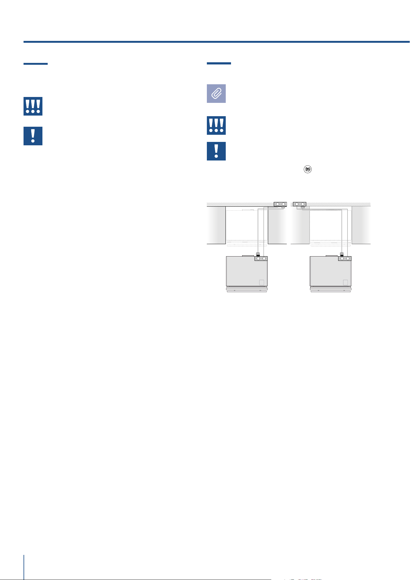
EW
E W
EW
E W
56
www.fhiaba.com · [email protected] · Info Line 800-344222
5.1 Transport to installation site
and unpacking
The appliance is very heavy.
Take maximum care during handling
to avoid injury.
The appliance should always be
transported in an upright position.
Avoid at all costs leaning it on its front
side.
It is recommended to use a manual transporting device
to move the appliance to the installation site, and only
at this point to remove the base of the packaging.
The appliance should always be transported in an
upright position.
If this is not possible, transport the appliance laying
on its rear side.
Once at the installation site, the appliance can be taken
o the pallet and positioned in the installation area.
5. PREPARING THE INSTALLATION
5.2 Electrical and Water connection
The Built-in Fhiaba filter cannot make
safe any water which is not already
suitable for human consumption.
The appliance should be connected only
to a potable water supply system.
Do not use extension cords or adapters.
Once the appliance has been connected
to the water system, turn the Ice Maker
off (touch the button
on control panel
to switch it off) before the main water is
shut off.
A Schuko 16 A socket with an ecient grounding
should be made available for the electrical mains
connection, as well as an omnipolar switch which can
easily be reached when the appliance is installed.
To connect to the water supply system (for appliances
equipped with ice makers) a tap with a male 3/4” con-
nection should be provided, which must also be easily
accessible once the appliance is installed.
The appliance is provided with a water supply hose
and seal kit which is suitable for high water pressure
and complies the Food Regulations.
The water filter cartridge, which is provided with the
appliance, should be installed according to the ac-
companying instructions.
Use only the new hose and the new gaskets which
are supplied with the appliance. Discard any hose and
gasket which may have previously been installed.
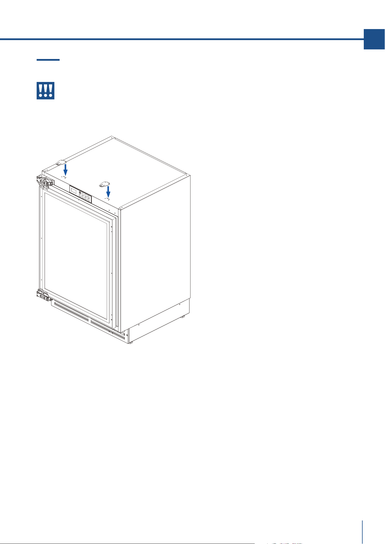
57
www.fhiaba.com · [email protected] · Info Line 800-344222
EN
www.fhiaba.com · [email protected] · Info Line 800-344222
5.3 Anti-Tip Bracket
The anti-tip bracket must be installed to
prevent the unit from tipping when doors
are fully opened.
TOP MOUNT
Operate as follows:
Anti-tip brackets kit provided with the use and care/
installation manual
> Fix the anti-tip brackets on to the top of the unit (see
picture above)
> Slide the units into its position in the opening. Level
the unit according to the cabinet design.
> Make sure the door opens completely and drill four
pilot holes in to the bottom of the counter top & fit
screws taking care not to pass through the counter
fully.

#1#2
#1#2
58
www.fhiaba.com · [email protected] · Info Line 800-344222
6. DOOR SWING
6.1 Change the opening direction of the
door (Indoor models)
> Open the door
> Remove the hinge plastic covers.
> Support the door in the open position and use a
screwdriver to remove the screws from both hinges.
> Do not remove the hinges from the door.
> Remove the little caps from the upper and lower
holes of the new position and place them in the holes
on the opposite side of the unit.
> Partially re-install screw #1 in the opposite holes of
the unit.
> Turn the door upside down and align the hinges with
screw #1 to re-position the door.
> Re-install screw #2 align the door and tighten all
screws securely.
> Check that the gasket is aligned with the plastic
outline of the front of the unit.
> Replace the plastic covers on the hinges.

#1#2
#1#2
59
www.fhiaba.com · [email protected] · Info Line 800-344222
EN
www.fhiaba.com · [email protected] · Info Line 800-344222
6.2 Change the opening direction of the
door (Outdoor models)
The hinges of the door of the Outdoor
models are spring preloaded so never
remove the hinges from the stainless
steel door.
> Open the door
> Support the door in the open position and use a
screwdriver to remove the screws from both hinges.
> Do not remove the hinges from the door.
> Remove the little caps from the upper and lower
holes of the new position and place them in the holes
on the opposite side of the unit.
> Turn the door upside down and align the hinges with
screw #1 to re-position the door.
> Re-install screw #2 align the door and tighten all
screws securely.
> Check that the gasket is aligned with the plastic
outline of the front of the unit.
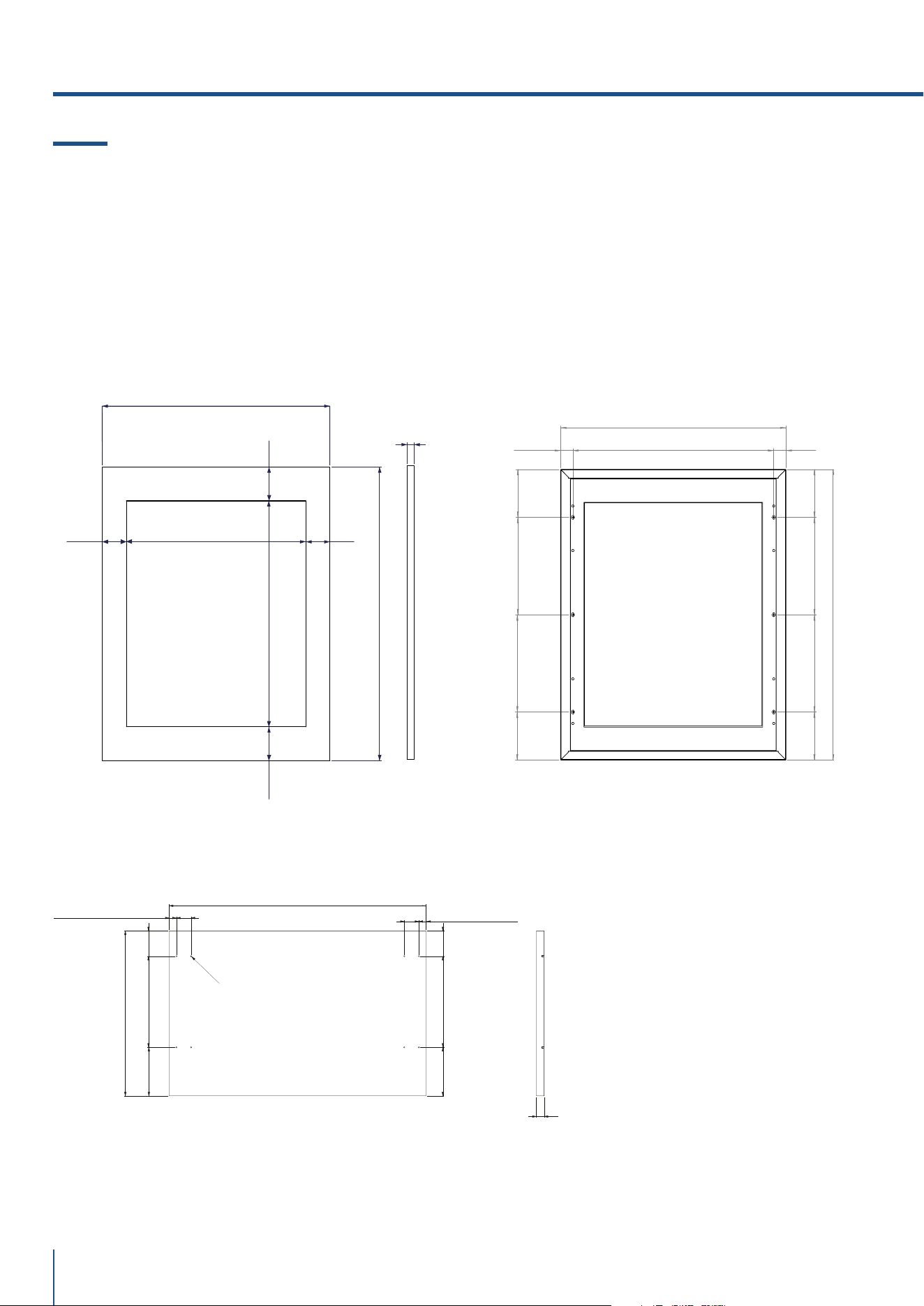
597 (23 1/2”)
770 (30 5/16”)
471 (18 35/64”)
592,8 (23 11/32”)
63 (2 31/64”) 63 (2 31/64”)
88,6 (3 31/64”)
88,6 (3 31/64”)
18 min -20 max
(45/64”min - 25/32” max)
32,5 (1 9/32”)
532 (23 1/2”)
32,5 (1 9/32”)
258 (30 5/16”)
127 (5”)
258 (30 5/16”)
597 (23 1/2”)
770 (30 5/16”)
127 (5”)
127 (5”)
127 (5”)
258 (30 5/16”)
258 (30 5/16”)
60
www.fhiaba.com · [email protected] · Info Line 800-344222
Positioning holes on decorative panels. UCB
and UCW models.
Integrated Frame Dimensions:
UC2D60 models
597 (23 1/2”)
383 (15 5/64”)
34 (1 3/8”)
17 (43/64”)
17 (43/64”)
59 (2 21/64”)212 (8 11/32”)
212 (8 11/32”)
113 (4 29/64”)
113 (4 29/64”)
34 (1 3/8”)
59 (2 21/64”)
Ø3 (1/8”) (x8)
18 min
(45/64” min)
7. PANEL MOUNTING
7.1 Integrated Panel Dimensions
INTEGRATED FRAME
Handles should be installed to the panel prior to in-
stalling overlay to door.
The thickness of the panel should be no less then
18mm (45/64”)/no more than 20mm (25/32”) and the
weight of the overlays should not exceed 10 kg (20
lbs)
Integrated Frame Dimensions:
UCB and UCW models
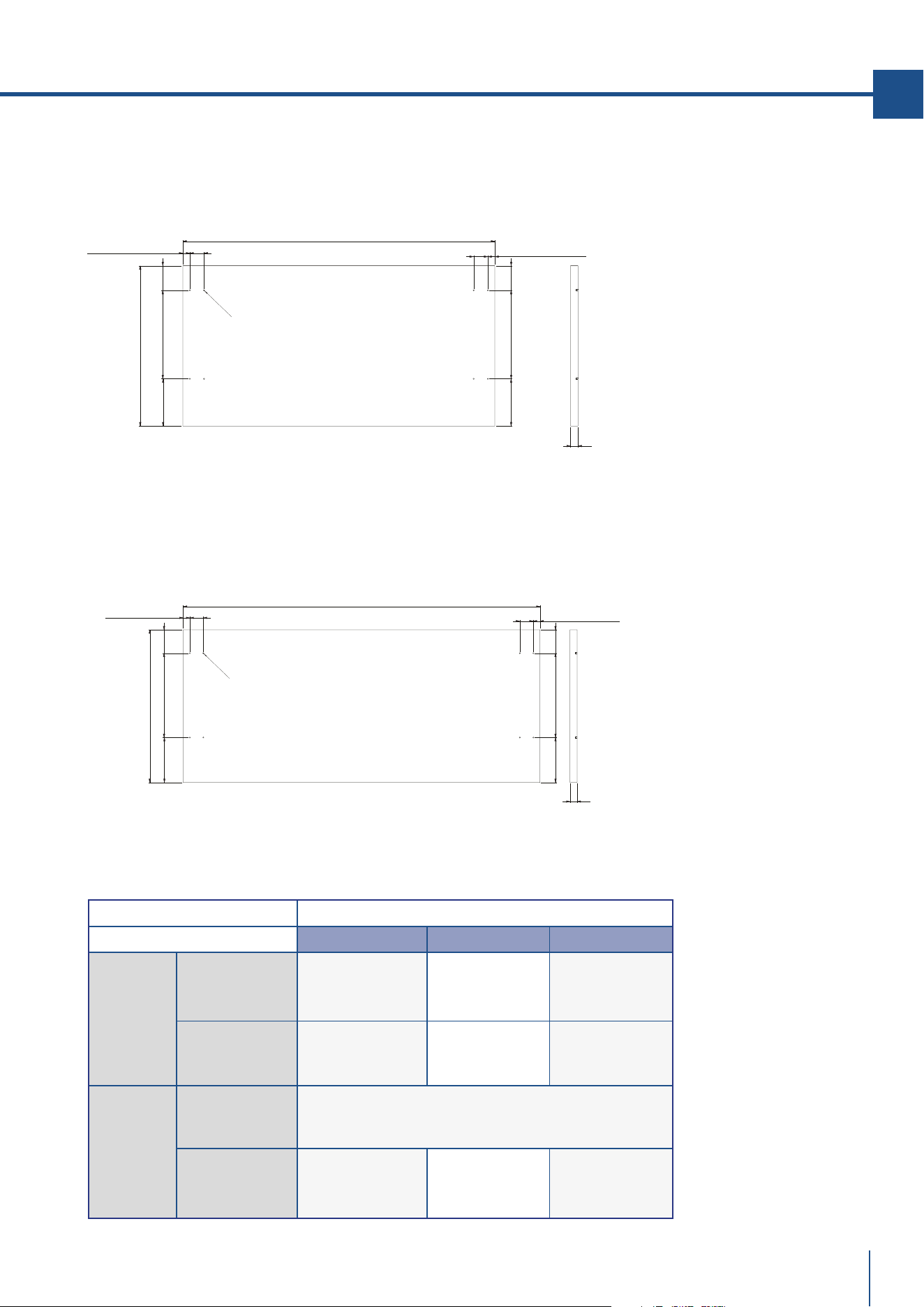
Premium Indoor models Decorative panel thickness
Width 60 cm (24") 75 cm (30") 90 cm (36")
Modelli
UCB
UCW
Thickness
min 18mm (45/64")
max 20mm (25/32")
- -
Max. weight max 8 kg (17 lb) - -
Modelli
UC2D60
UC2D75
UC2D90
Thickness
min 18mm (45/64")
max 25mm (1")
Max. weight
Single panel
max 8 kg (17 lb) max 10 kg (22 lb) max 12 kg (26 lb)
61
www.fhiaba.com · [email protected] · Info Line 800-344222
EN
www.fhiaba.com · [email protected] · Info Line 800-344222
Integrated Frame Dimensions:
UC2D75 models
Integrated Frame Dimensions:
UC2D90 models
747 (29 13/32”)
383 (15 5/64”)
17 (43/64”)
17 (43/64”)
212 (8 11/32”)
212 (8 11/32”)
113 (4 29/64”)
113 (4 29/64”)
34 (1 3/8”) 34 (1 3/8”)
59 (2 21/64”)
59 (2 21/64”)
Ø3 (1/8”) (x8)
18 min
(45/64” min)
897 (35 5/16”)
383 (15 5/64”)
34 (1 3/8”)
17 (43/64”)
17 (43/64”)
59 (2 21/64”)
212 (8 11/32”)
113 (4 29/64”)
59 (2 21/64”)
212 (8 11/32”)
113 (4 29/64”)
34 (1 3/8”)
Ø3 (1/8”) (x8)
18 min
(45/64” min)
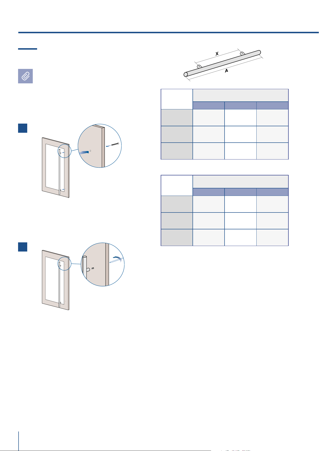
62
www.fhiaba.com · [email protected] · Info Line 800-344222
7.2 Mounting the handles
Handles will have to be mounted on the
panels before panels are applied to the
fridge.
Operate as follows:
> Drill two holes on the back of the panels
according to the drawing below [ 1 ].
> Place the handle on top of the holes and insert
the screws through the panel and into the handle
support [ 2 ].
Ø 30 mm
HANDLE PRODUCT CODE
HO8 H07 H05
Length A
794 mm
(31 1/4”)
644 mm
(25 3/8”)
494 mm
(19 5/8”)
Distance
between
fixing points X
480 mm
(18 7/8”)
490 mm
(19 1/4”)
340 mm
(13 3/8”)
Series 90 75 60
Ø 18 mm
HANDLE PRODUCT CODE
HC8 HC7 HC5
Length A
794 mm
(31 1/4”)
644 mm
(25 3/8”)
494 mm
(19 5/8”)
Distance
between
fixing points X
776 mm
(30 1/2”)
626 mm
(24 5/8”)
476 mm
(18 3/4”)
Series 90 75 60
2
1
7. PANEL MOUNTING
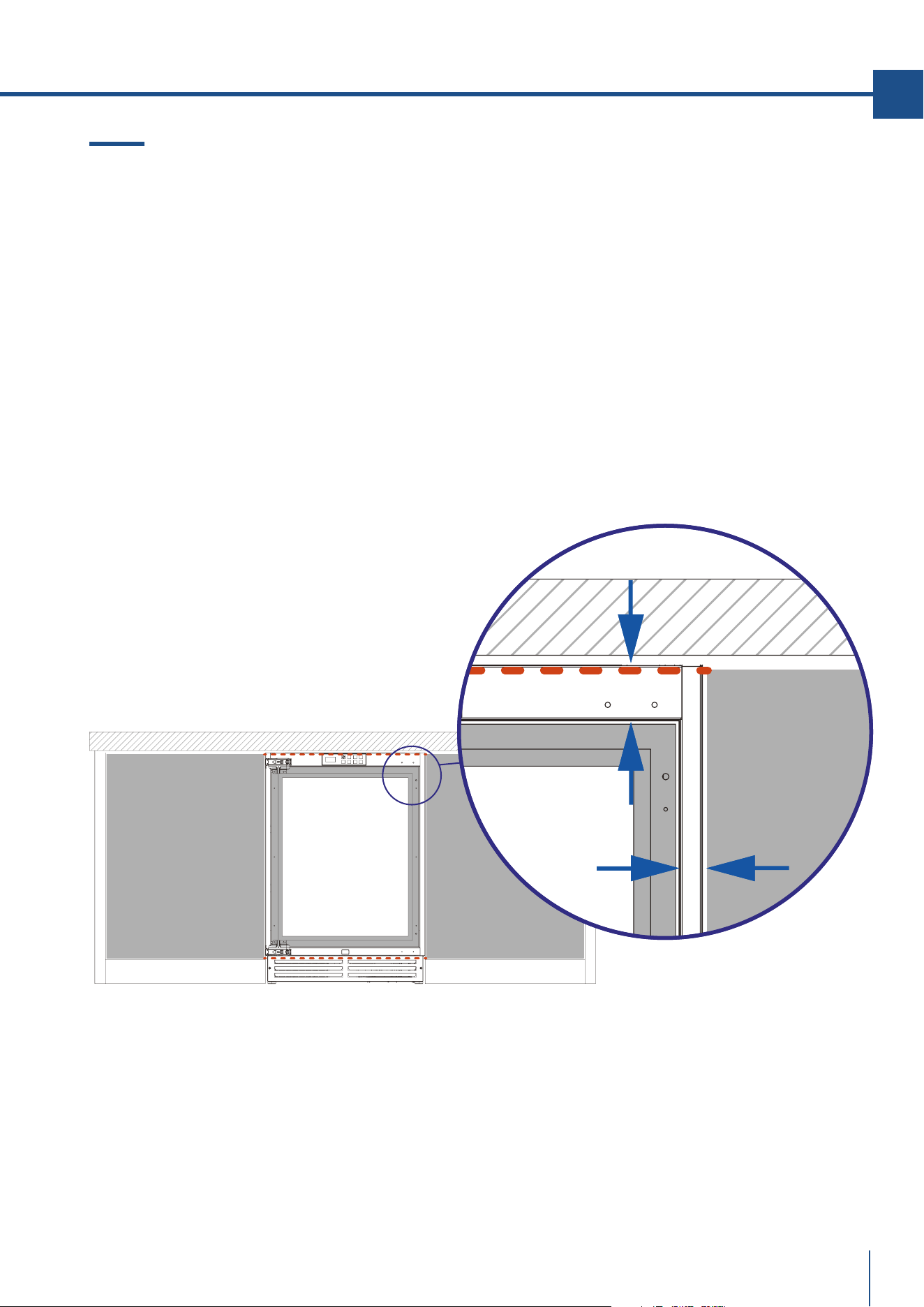
63
www.fhiaba.com · [email protected] · Info Line 800-344222
EN
www.fhiaba.com · [email protected] · Info Line 800-344222
7.3 Installation of decorative panels
Once the unit is positioned inside the opening and the
screws of the anti-tipping supports are tightened, the
machine will no longer move and it will be possible to
take the measures for aligning the overlay panel.
> Measure the distance between the aluminum frame
of the door and the adjacent furniture panels. Subtract
the millimeters needed for the dimension of the gap
that you want to be left between the panels.
> Center the panel horizontally and vertically, marking
some references on it.
> Refer the taken measurements to the back of the
panel.
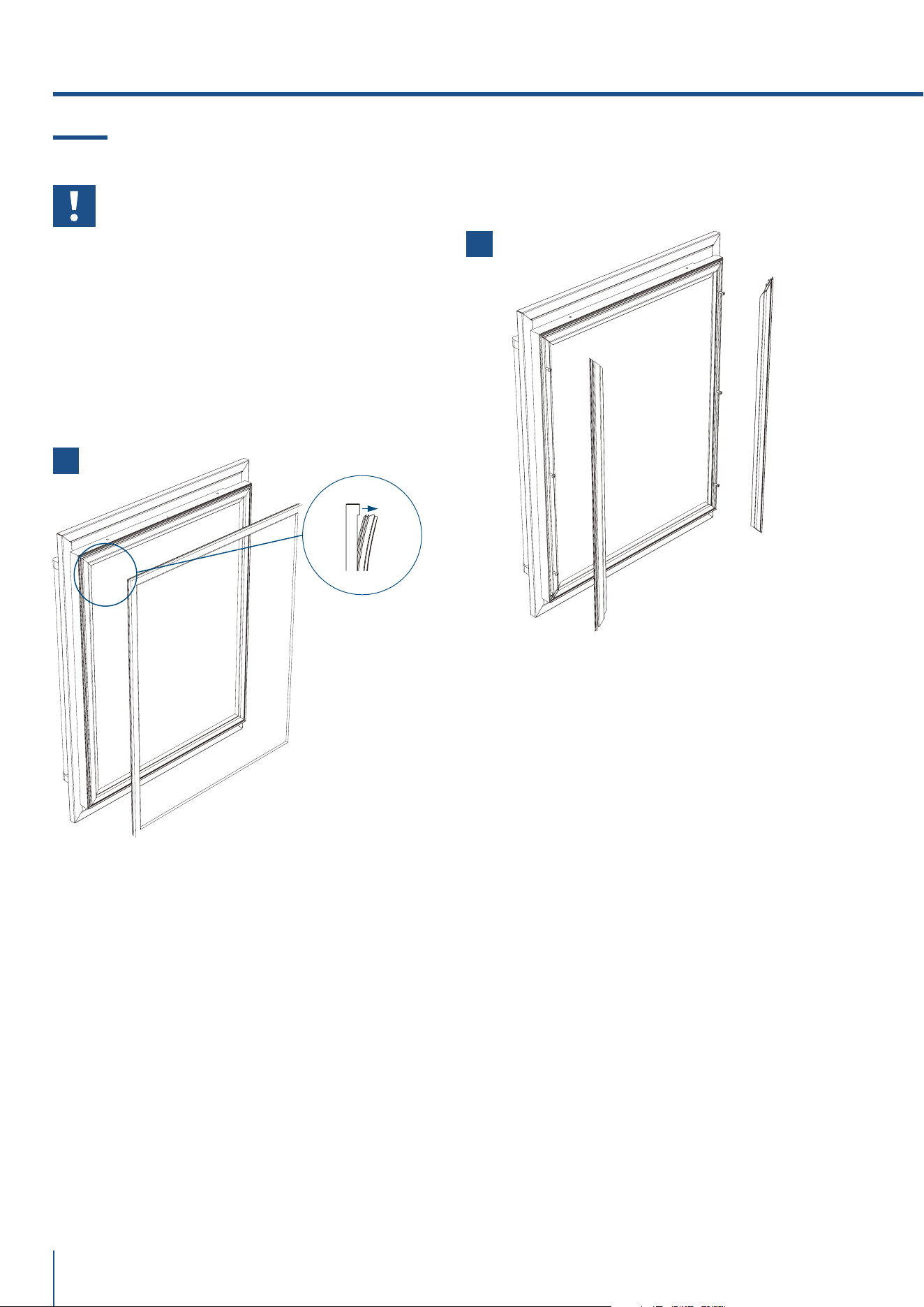
1
2
64
www.fhiaba.com · [email protected] · Info Line 800-344222
> Remove the two vertical gasket channel trims start-
ing from the corner [ 2 ].
7.4 Mounting panel to the door
Before beginning installation make sure
handle is installed to the panel prior to
installing panel to door.
Operate as follows:
> Open the door and remove the gasket carefully
starting at the corner. Continue to pull gasket free
from gasket channel [ 1 ].
> Upon removal, lay gasket down on a flat surface.
7. PANEL MOUNTING
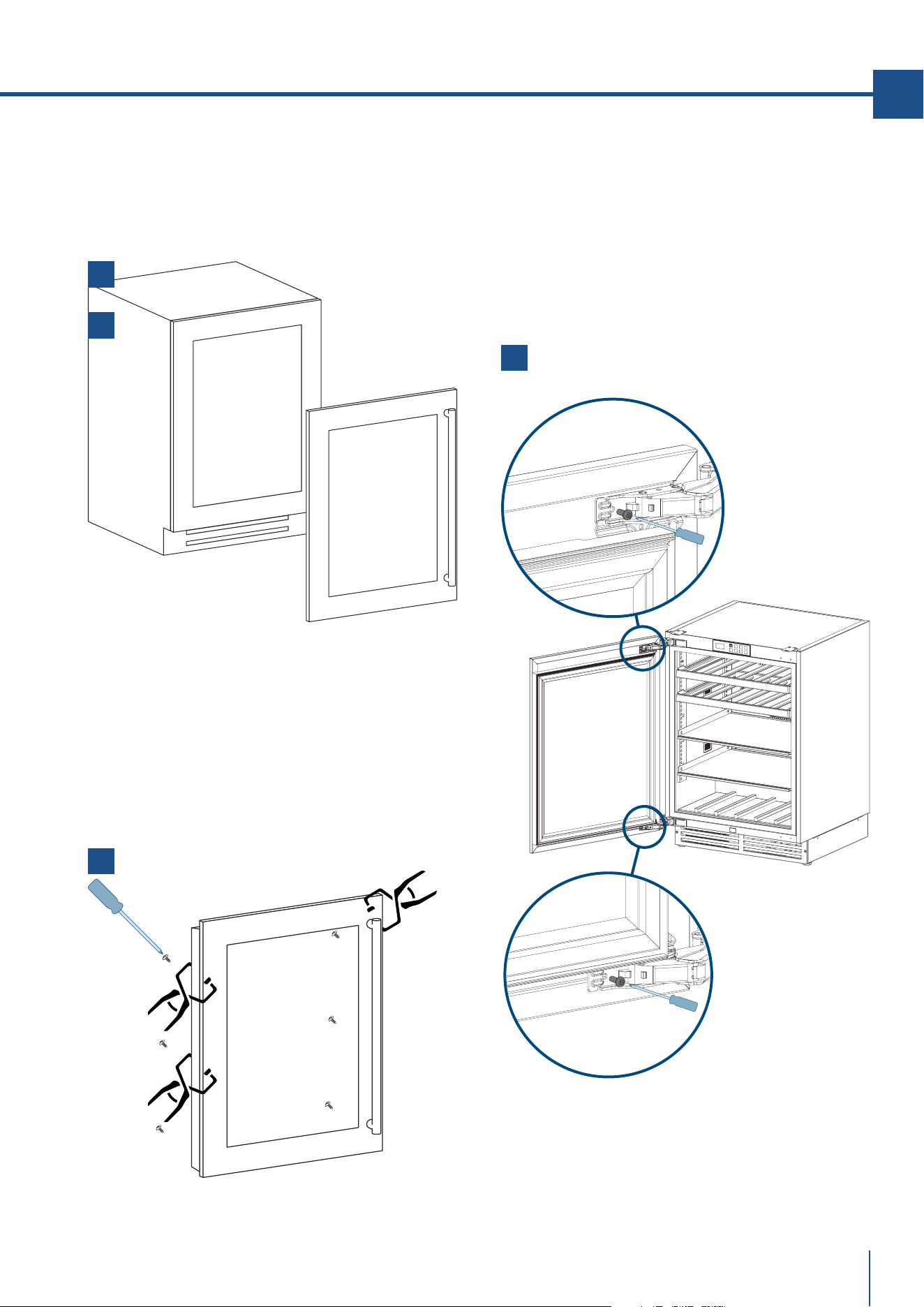
3
5
4
65
www.fhiaba.com · [email protected] · Info Line 800-344222
EN
www.fhiaba.com · [email protected] · Info Line 800-344222
> Locate 6 of the M5x38 mm screw provided with your
unit [ 4 ]. Place one screw into each of the 6 holes
and screw down and do not overtighten screws.
> Remove tape and clamps from door.
> Reposition the two vertical gasket channel trims
starting from the corner.
> Reposition gasket carefully starting from the
corner.
3
4
> Once the correct alignment of the panel has been
checked, place the last two screws onto the top and
bottom hinge [ 5 ] .
> Open the door.
> Position the panel in front of the glass door, respec-
ting the references given in point 7.3 [ 3 ] .
> Fix the panel with clamps making sure not to indent
the face of the panel.
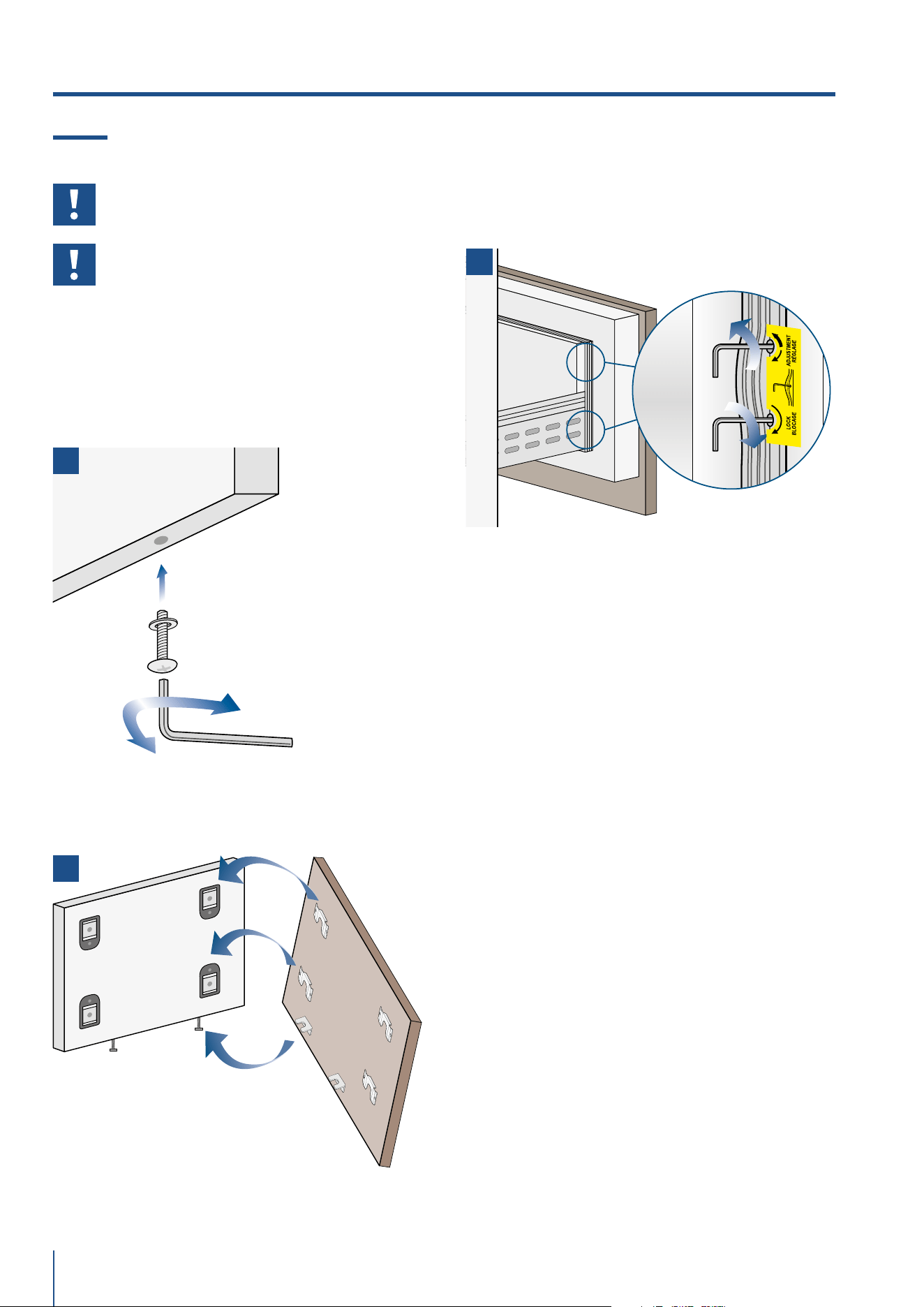
1
3
2
66
www.fhiaba.com · [email protected] · Info Line 800-344222
7.5 Mounting panels to the drawers
Before beginning installation make sure
handle is installed to the panel prior to
installing panel to door.
Once all brackets and small brackets
have been applied to the panels, you can
begin installing the bottom drawer.
Operate as follows:
> Partially tighten the screw to the fixing [ 1 ].
> Hook the bottom drawer panel starting from the fix-
ings on the bottom [ 2 ].
> Depth alignment: working from the inside of the
drawer, after lifting up the magnetic seal, adjust the
panel position so it is closer to or further away from
the door using the holes and then secure the panel
using the holes [ 3 ].
7. PANEL MOUNTING
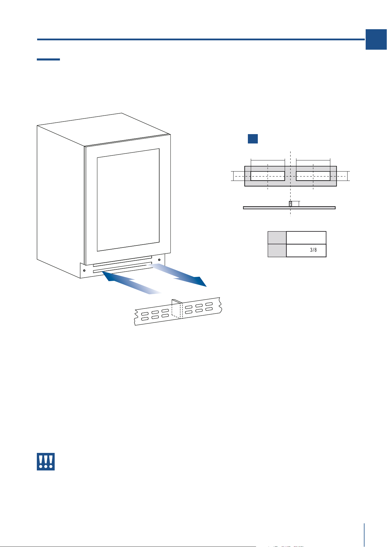
air-in
air-out
plinth
separator
1
A
BB
A
20mm
200mm (7 7
/8
")
A
B
60mm (2 ")
67
www.fhiaba.com · [email protected] · Info Line 800-344222
EN
www.fhiaba.com · [email protected] · Info Line 800-344222
8. VENTILATION
8.1 Ventilation
A forced air system assures ventilation through a
grille positioned in the lower front part of the unit.
If the kitchen design includes a kickplate (plinth), it
must be positioned at least 1/4” away from the face
of the kick area and be ventilated in such a manner
as to provide 50% of the material removed for proper
ventilation and operation of the appliance.
Holes can be in any shape and size, as long as the total
area of the punched part equals 50% of the kickplate
and align with the intake and output openings of the
appliance. [ 1 ]
The air intake and outlet must not be
blocked or covered in any way.
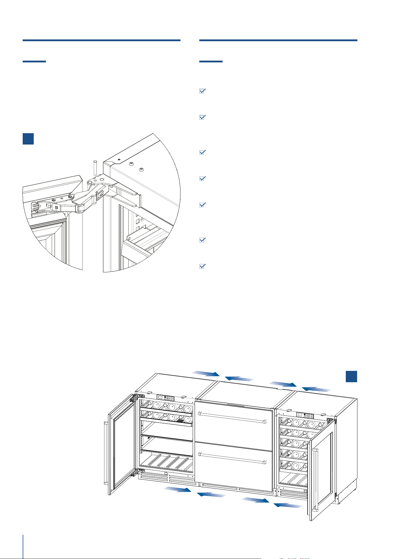
68
www.fhiaba.com · [email protected] · Info Line 800-344222
2
9.1 Door swing, door stop
The Door of the unit will open 115° straight from the
factory.
You can stop the door at 90° by using the provided pin
and before placing the unit under the counter
90° hinge stop installation
> Open the door at 90°
> Slide hinge pin into hole as shown in picture [ 1 ]
> You might need an hammer to gently tap the pin into
its final position
9. DOOR STOP
1
10.1 Post installation checklist
Check that the front levelling feet have been pro-
perly installed.
Check that the connection to the water system
does not have any leaks and that the shuto valve
is easily accessible.
Check that the electrical connection is correctly
installed and that the socket is easily accessible.
Check for perfect alignment of the appliance with
adjacent structures.
Check that all adhesive tape and external or in-
ternal temporary protective devices have been re-
moved.
Check for perfect closing of the doors and the
smooth sliding of the drawers and shelves.
Check the alignment if 2 or more models are in-
stalled side by side; (there are no kits for joining the
equipment). [ 2 ]
10. POST INSTALLATION
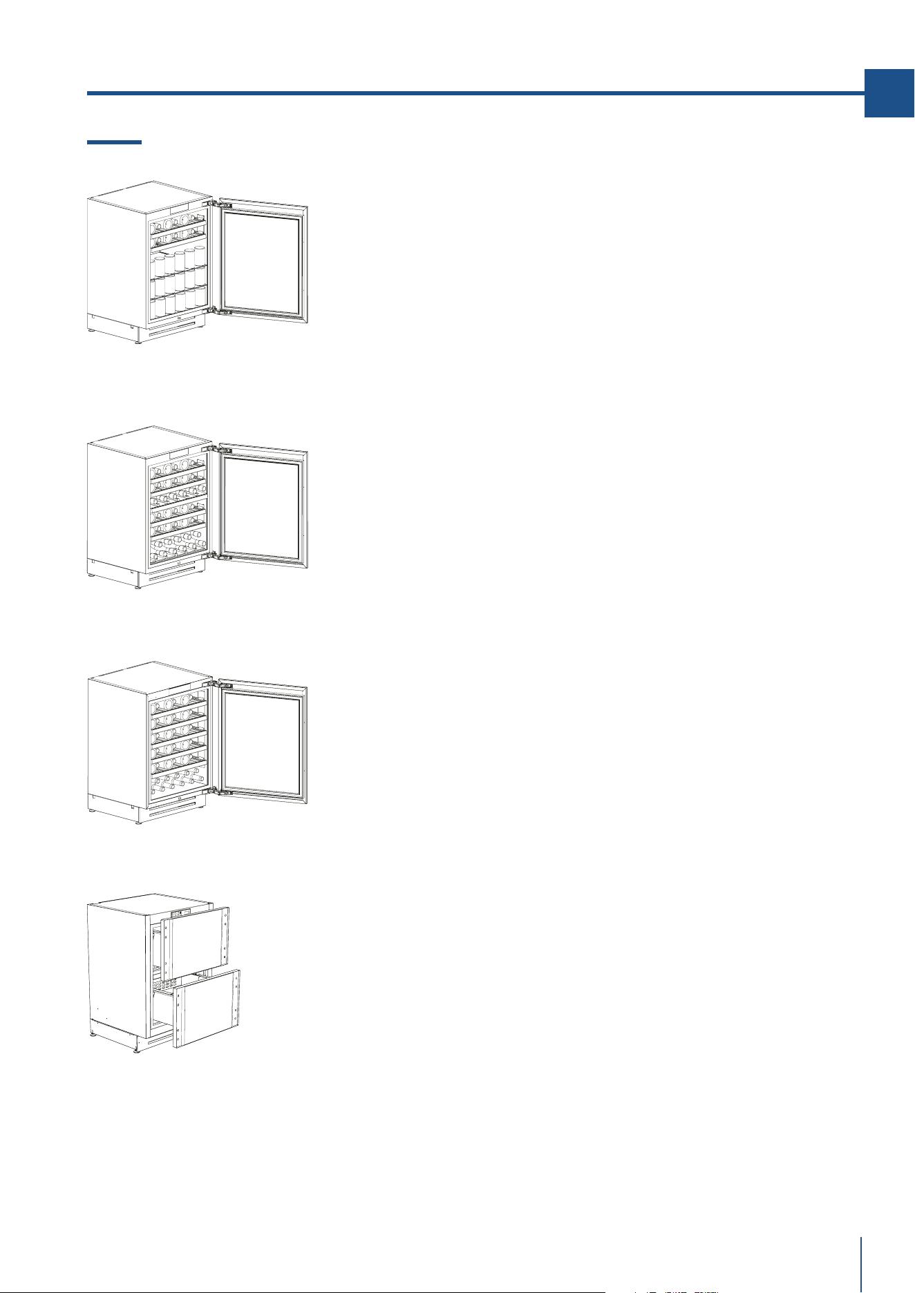
69
www.fhiaba.com · [email protected] · Info Line 800-344222
EN
www.fhiaba.com · [email protected] · Info Line 800-344222
11.1 Main components
BEVERAGE:
> Inner cabinet in AISI 304 stainless steel
> Outer cabinet in AISI 304 stainless steel
> Interactive control panel with OLED display
> Modular shelf positioning system
> Bead-blasted stainless steel internal drawer with tempered glass front
> Bottle storage shelves
> White and Amber LED lighting
> Reversible door
> Glass door with UV protection and Argon gas
DUAL TEMPERATURE WINE CELLAR:
> Inner cabinet in AISI 304 stainless steel
> Outer cabinet in AISI 304 stainless steel
> Interactive control panel with OLED display
> Modular shelf positioning system
> Bottle storage shelves
> White and Amber LED lighting
> Reversible door
> Glass door with UV protection and Argon gas
SINGLE TEMPERATURE WINE CELLAR:
> Inner cabinet in AISI 304 stainless steel
> Outer cabinet in AISI 304 stainless steel
> Interactive control panel with OLED display
> Modular shelf positioning system
> Bottle storage shelves
> White and Amber LED lighting
> Reversible door
> Glass door with UV protection and Argon gas
TRIMODE SLIDING DRAWERS:
> Inner cabinet in AISI 304 stainless steel
> Outer cabinet in AISI 304 stainless steel
> Interactive control panel with OLED display
> Water filter (*)
> Modular shelf positioning system
> Bead-blasted stainless steel internal drawer with tempered glass front
> Automatic ice maker (*)
> LED lighting
> TriMode freezer drawers which can be converted into a fridge or Fresco
compartment
(*) on some models
11. FEATURES

70
www.fhiaba.com · [email protected] · Info Line 800-344222
UNIT
ON / OFF
UNIT
ON / OFF
LIGHTLIGHT
MENUMENU INFOINFO
CONFIRMCONFIRM BACKBACK
UPUP DOWNDOWN
12.1 Main control panel
Beverage Center 1 Single Zone
Wine Cellar 1 Single Zone
TriMode / Convertible Drawers
Beverage Center Dual Zone
Wine Cellar Dual Zone
12. GETTING STARTED
71
www.fhiaba.com · [email protected] · Info Line 800-344222
EN
www.fhiaba.com · [email protected] · Info Line 800-344222
Unit ON/OFF
Main menu access button
Compartment lighting ON/OFF button
Information menu button
Confirm operation button
Exit menu/Whole or decimal number
selection (for Celsius only)
Up
Down
12.2 Layout
The control panel is made up of a 1.51” 128x64 pixel
display with an 8-button resistive keypad, including
backlit ON/OFF button. The low-voltage power sup-
ply is provided to the control board via a CAN bus
connection cable.
12.3 Functions
> Displays the set-point of the one or two com-
partments (WINE CELLAR/BEVERAGE CENTER mo-
dels only)
> Displays the operating variables
> For setting the temperature set-point
> Notification of anomalous faulty events such as:
> TEMPERATURE ALARMS
> FAULTS
> WARNINGS
> Cloud connection via accessory Ethernet, Wi-Fi, 3G
modules.
12.4 Keypad
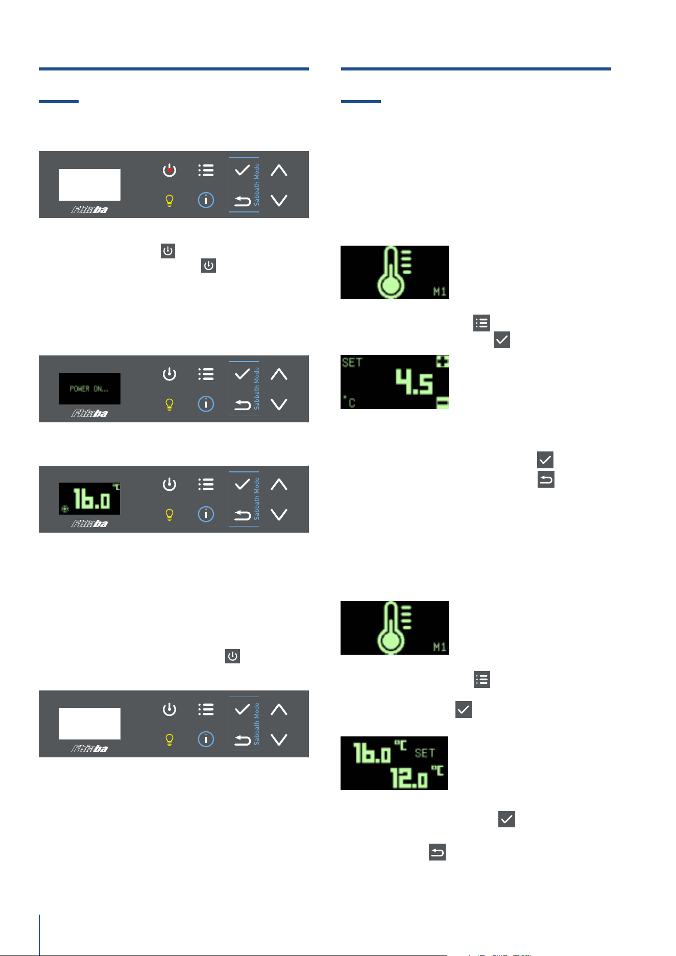
72
www.fhiaba.com · [email protected] · Info Line 800-344222
13.1 Switching ON/OFF 14.1 How to adjust the temperature to
meet user requirements
When the appliance is switched off, the backlight
in the ON/OFF button
is RED. Press and brie-
fly hold the ON/OFF button
to turn the ap-
pliance on. The text POWER ON... appears for a
few seconds.
Press and hold the ON/OFF button
until the ap-
pliance is switched o.
Switching ON
Entering the set-point
Entering set-points
Switching OFF
> Press the MENU button
to call up the M1 frame
> Press the CONFIRM button
> Enter the new set-point value using the UP/DOWN
buttons. Press the CONFIRM button
to set the
new value or press the BACK button
to exit the
menu without saving the new value.
> Press the MENU button
to call up the M1 frame
> Select the set-point you wish to edit by pressing
the CONFIRM button
(the set-point selected for
editing starts to flash)
> Enter the new set-point value using the UP/DOWN
buttons. Press the CONFIRM
button to set the
new value. Both set-point values are saved. Press
the BACK button
to exit the menu without saving
the new values.
13. SWITCHING ON/OFF 14. ADJUSTMENTS
Beverage Center Single Zone
Wine Cellar Single Zone
TriMode / Convertible Drawers
Beverage Center Dual Zone
Wine Cellar Dual Zone

73
www.fhiaba.com · [email protected] · Info Line 800-344222
EN
www.fhiaba.com · [email protected] · Info Line 800-344222
15.1 Event notifications
Pre-alarm status
When the temperature limits are exceeded but the
alarm delay time has not yet expired, the device is
in pre-alarm status. The UP arrow icon appears
during ‘high temperature’ pre-alarm status. The
DOWN arrow icon appears during ‘low temperature’
pre-alarm status.
Alarm detection
When a temperature alarm arises, the THERMOME-
TER icon appears, the buzzer goes o and the red
LED flashes. Press any button to open the EVENTS
LIST and turn the buzzer o. Press the BACK button
to exit the EVENTS LIST. If the alarm condition
resolves itself, the buzzer goes o automatically.
Active alarm
During a high/low temperature alarm condition, the
UP/DOWN arrow icon with flashing red LED appe-
ars on the left-hand side of the display. If the alarm
condition resolves itself, the buzzer goes o auto-
matically.
Fault detection
When a fault arises, the TOOL icon appears, the buz-
zer sounds and the red LED flashes. Press any but-
ton to open the EVENTS LIST and turn the buzzer
o. Press the BACK button
to exit the EVENTS
LIST.
If the alarm condition resolves itself, the buzzer
goes o automatically.
15. EVENT NOTIFICATIONS
Active fault
During a fault condition, the TOOL icon with flashing
red LED appears on the left-hand side of the display.
If the fault condition resolves itself, the buzzer goes
o automatically.
Rectified event notification
If a temperature or fault condition resolves itself
before the EVENTS LIST has been consulted, the
‘message’ icon appears on the left-hand side of the
frame.
Open door warning
If the door has been left open, after a pre-set delay
time, the icon shown in the figure appears and the
buzzer goes o.
Voltage out of range warning
The supply voltage WARNING fills the whole frame
with a dedicated icon. The buzzer sounds when any
button is pressed or the time set in the BUF para-
meter has expired. If the problem is not rectified,
the warning will be repeated after 24 hours.
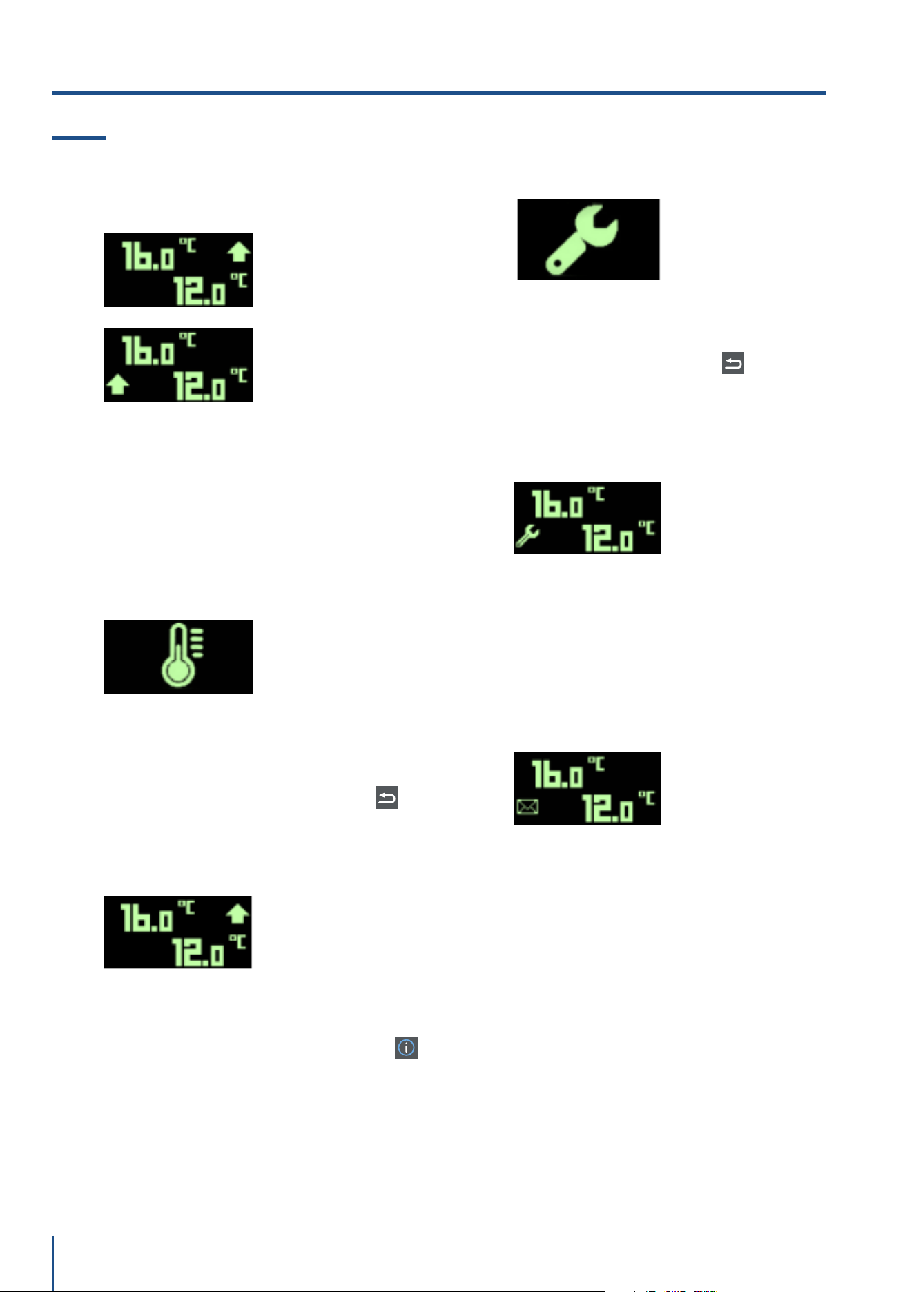
74
www.fhiaba.com · [email protected] · Info Line 800-344222
15.2 Wine cellar and beverage event
notifications
Pre-alarm status
Top compartment
pre-alarm
Bottom compartment
pre-alarm
When the temperature limits are exceeded but the
alarm delay time has not yet expired, the device
is in pre-alarm status for one or both of the com-
partments. The UP arrow icon appears alongside
the compartment’s set-point value during ‘high tem-
perature’ pre-alarm status. The DOWN arrow icon
appears alongside the compartment’s set-point va-
lue during ‘low temperature’ pre-alarm status.
Alarm detection
When a temperature alarm arises in one or both
of the compartments, the THERMOMETER icon ap-
pears, the buzzer sounds and the red LED flashes.
Press the INFO button to open the EVENTS LIST and
turn the buzzer o. Press the BACK button
to
exit the EVENTS LIST. If the alarm condition resol-
ves itself, the buzzer goes o automatically.
Active alarm
During a high/low temperature alarm condition, the
UP/DOWN arrow icon with flashing red LED appe-
ars alongside the compartment’s set-point value
and the buzzer sounds. Press the INFO button
to open the EVENTS LIST and turn the buzzer o. If
the alarm condition resolves itself, the buzzer goes
o automatically.
Fault detection
When a fault arises, the TOOL icon appears, the
buzzer sounds and the red LED flashes. Press the
INFO button to open the EVENTS LIST and turn the
buzzer o. Press the BACK button
to exit the
EVENTS LIST.
If the alarm condition resolves itself, the buzzer
goes o automatically.
Active fault
During a fault condition aecting one or both com-
partments, the TOOL icon with flashing red LED ap-
pears on the left-hand side of the display. Press the
INFO button to open the EVENTS LIST and turn the
buzzer o.
If the fault condition resolves itself, the buzzer goes
o automatically.
Rectified event notification
If a temperature or fault condition resolves itself
before the EVENTS LIST has been consulted, the
‘message’ icon appears on the left-hand side of the
frame.
15. EVENT NOTIFICATIONS
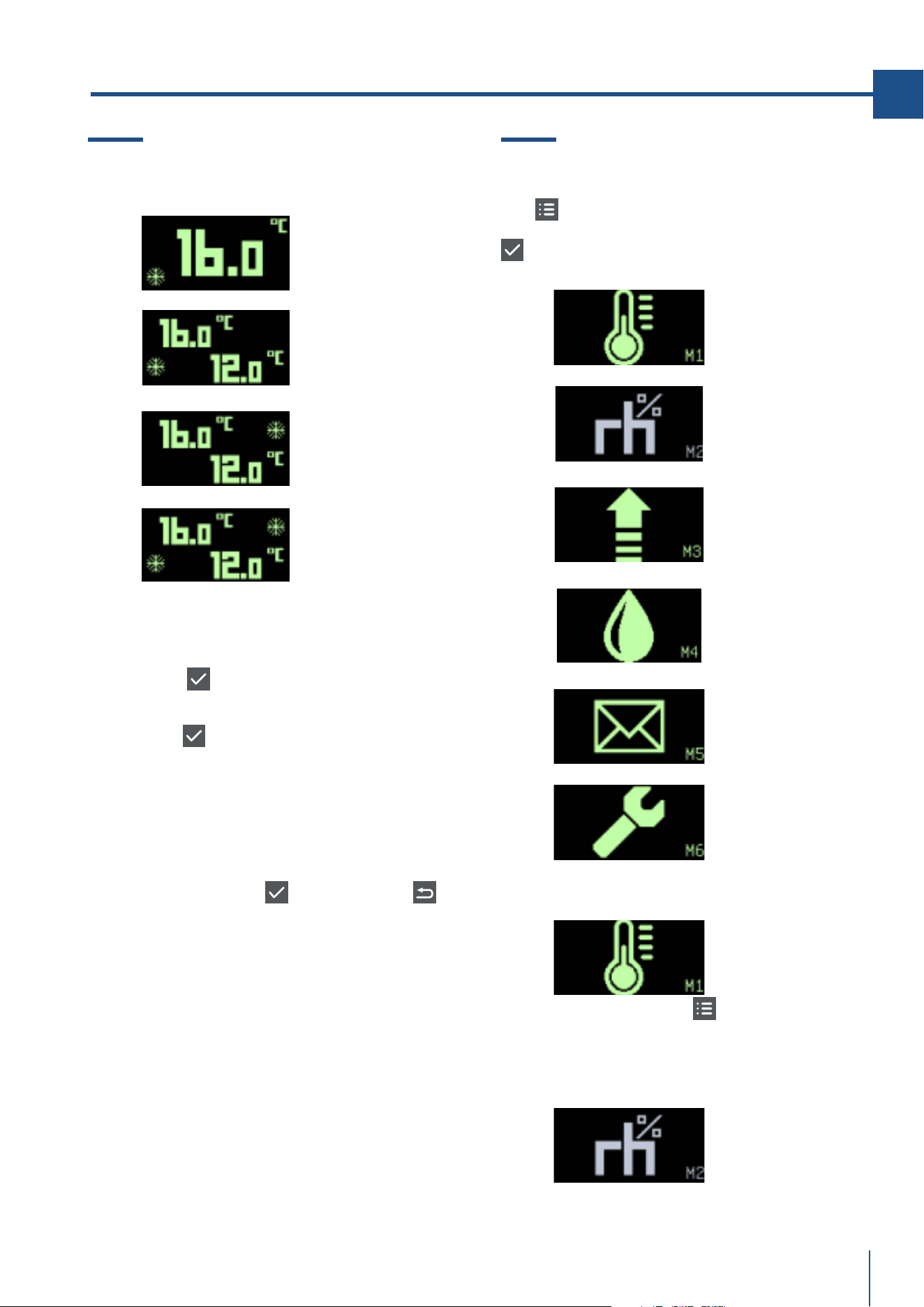
75
www.fhiaba.com · [email protected] · Info Line 800-344222
EN
www.fhiaba.com · [email protected] · Info Line 800-344222
16. SETTINGS AND SPECIAL FUNCTIONS
16.1 Special functions
Chill and serve
Chill and serve active
Chill and Serve
active, Zone 1
Chill and Serve
active, Zone 2
Chill and Serve active
in both compartments
Set-point forcing to 4 degrees in the relative
compartment for one hour (Wine Cellar only, even
with only one compartment). This is activated/
deactivated by simultaneously pressing:
> CONFIRM
+ UP for single-compartment
Wine Cellars or for compartment 1 of dual com-
partment Wine Cellars.
> CONFIRM
+ DOWN for compartment 2 of
dual compartment Wine Cellars
Activation is confirmed by the buzzer sounding
and the snowflake icon appearing on the screen.
Sabbath mode
This is activated/deactivated by simultaneously
pressing the CONFIRM
+ BACK buttons
.
> Temperature stabilisation is carried out based
on the time parameters set by the manufacturer
> The fans come on at the same time as the com-
pressor
> The evaporator fans are not inhibited when the
door is open
> Defrosting is inhibited
> All alarms are disabled
> Light outputs always switched off
> The display stays off
16.2 User menus
These can be accessed by pressing the MENU but-
ton
. Select the required menu using the UP/
DOWN buttons and pressing the CONFIRM button
. The menu index, from M1 to M6 is shown in
the bottom right-hand corner of the display.
Temperature set-point
setting
Humidity set-point
setting
Alarm limits setting
Start defrost
operation
Events list
Service menu
Entering the set-point
Press the MENU button
with frame M1 se-
lected to access the temperature set-point set-
ting. See Chapter 3.0
Humidity set-point setting
Function not enabled

76
www.fhiaba.com · [email protected] · Info Line 800-344222
Start defrost operation
Single compartment
Home Page
Dual compartment
Wine Cellar
Home Page
With frame M4 selected, press the CONFIRM but-
ton to start a defrost operation (if the right condi-
tions for execution are met). If conditions are not
met, the X frame appears (request denied).
WAIT PHASE
The defrosting operation may include an initial
wait time during which the 00:00 timer does not
increase until the cycle actually starts.
PHASE ACTIVE
During the defrost operation the progress bar fills
up from left to right and the timer starts counting.
The value displayed at the centre of the frame in-
dicates the temperature in the compartment whi-
le the value on the left shows the temperature of
the evaporator.
ABORT
Defrosting can be aborted by pressing the MENU
button during the wait time and during execution,
but not during the dripping phase. Once defro-
sting has been completed, the display returns to
the Home page. If a dripping time is envisaged
the Drip icon appears and once this has expired
the display returns to the Home page.
AUTOMATIC DEFROST
If defrosting is started automatically by the con-
troller, the DEFROST frame does not appear, in-
stead the Home Page remains showing the de-
frost icon.
Event icons
High temperature
Low temperature
High temp. due to open door
High board temperature
Probe fault
16. SETTINGS AND SPECIAL FUNCTIONS
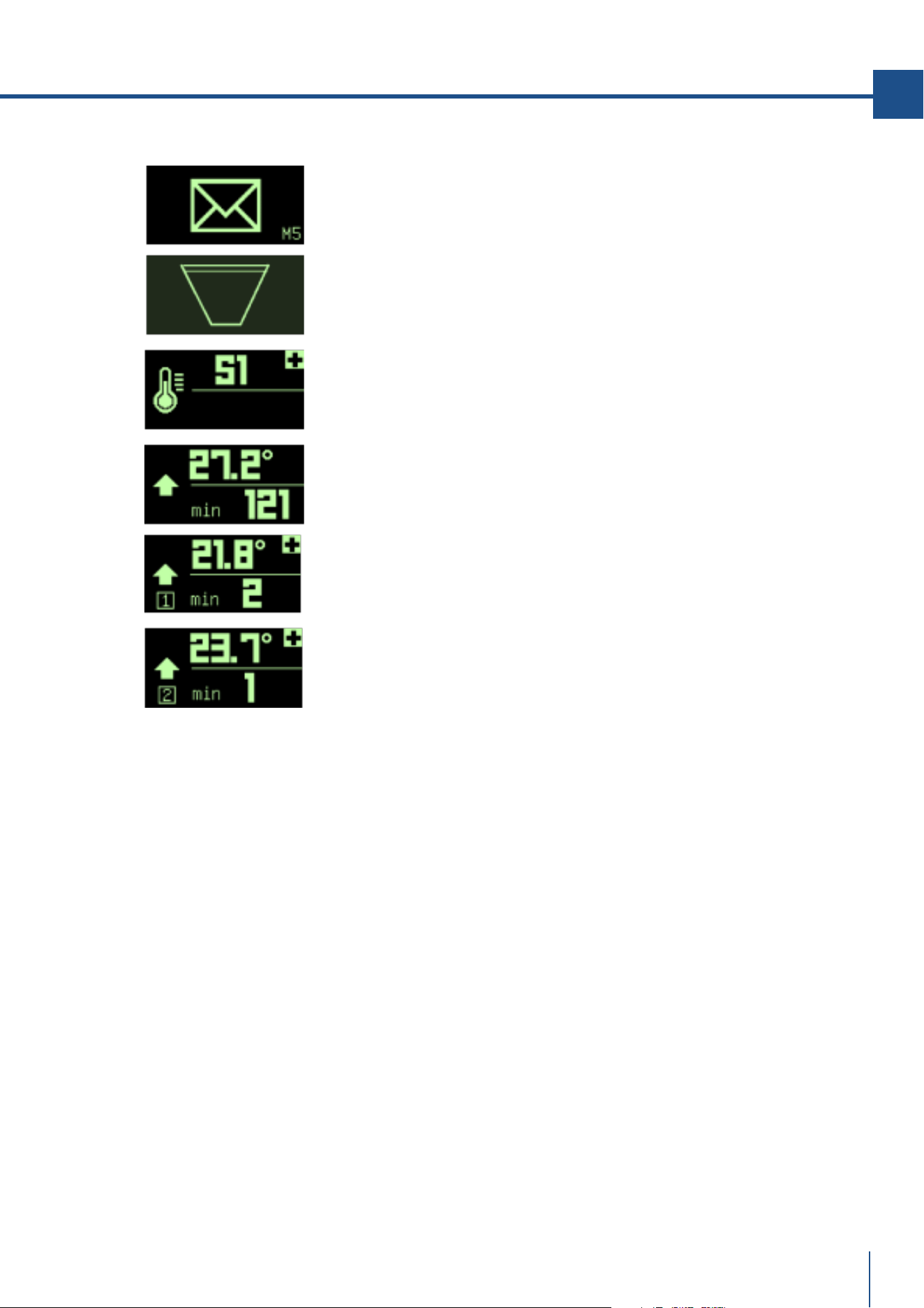
77
www.fhiaba.com · [email protected] · Info Line 800-344222
EN
www.fhiaba.com · [email protected] · Info Line 800-344222
Events list
With the M5 frame selected, press the CONFIRM
button to call up the EVENTS LIST. If the list is
empty, the empty trash can icon appears for 3
seconds after which the display returns to the
Home Page. If there are any events in the list,
the + symbol shows that other events have been
recorded which can be scrolled through using the
UP button.
If the display panel is switched off any recorded
events are deleted as the device does not have an
internal clock.
Be sure to check event logs prior to trying to re-
set the power as a troubleshooting method.
FAULT RECORD STRUCTURE
Representative Icon — Fault reference The frame
alongside shows an example of an S1 thermostat
sensor fault.
ALARM RECORD STRUCTURE
Representative icon — Peak — Duration in minu-
tes The frame alongside represents a high tem-
perature alarm
ALARM RECORD STRUCTURE FOR WINE CELLAR
Representative icon - Compartment index — Peak
— Duration in minutes
The frame alongside shows a high temperature
alarm for compartment 1
and a temperature alarm for compartment 2.

78
www.fhiaba.com · [email protected] · Info Line 800-344222
17.1 Lighting
The beverage centre is lit up with white LED
lights.
The Wine Cellars are lit up with amber and white
LED strip lights. Amber light for lighting during
wine aging and white for lighting up the cellar
when the door is opened.
The TriMode drawers are lit up with white LED
lights.
In the event of faults and/or breakdowns in the
lighting system, contact Fhiaba Service.
18.1 General directions
Your Fhiaba is designed to ensure precise, con-
stant temperatures and appropriate humidity le-
vels in all compartments.
Nevertheless, to properly preserve all of your fo-
ods, it is not enough to have an excellent refri-
gerator. It is also necessary to understand best
practices for correct food preservation.
Do bear in mind that all foods will inevitably
change their characteristics over the passage of
time. This change begins long before the food is
consumed, since foods contain micro organisms
which multiply and can cause deterioration. This
process occurs more rapidly due to improper
handling, preservation temperatures and humi-
dity levels.
It is therefore recommended to follow the direc-
tions presented below which will permit using
your appliance in the most effective and safe
manner to keep your foods and beverages in the
best way for as long as possible.
Bear in mind that TriMode drawer models con-
figured as Fresco compartments are best for
preserving the most delicate fresh foods, since it
ensures constant average temperature near fre-
ezing.
17. LIGHTING 18. GENERAL DIRECTIONS
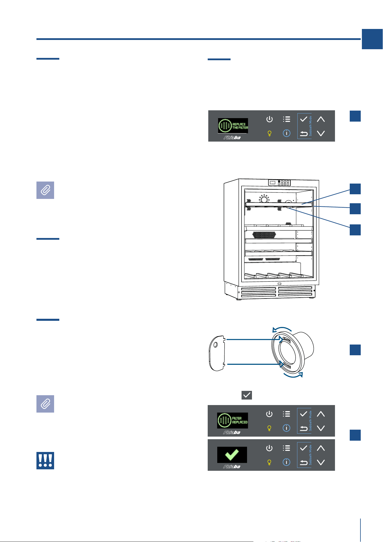
79
www.fhiaba.com · [email protected] · Info Line 800-344222
EN
www.fhiaba.com · [email protected] · Info Line 800-344222
> The request to change the filter appears on the
display [ 1 ], replace the filter.
> Remove the upper wooden shelf [ 2 ] and remo-
ve its side guide [ 3 ].
At the bottom is the filter [ 4 ].
> Insert the appropriate key, turn, remove the
filter and replace it with the new one.
Then insert the lateral runner and the shelf. [ 5 ].
> Reset the message on the display by holding
down OK
( ) [ 6 ].
19.4 Replacement of “activated carbon
filter”.
1
2
3
4
5
6
19. CARE AND CLEANING
19.1 Care and Cleaning
To clean the parts made of steel use a microfiber
cloth and the sponge provided in the kit with the
appliance. Always use the cloth and sponge in the
direction of the steel’s satin finish.
> Every now and then, to polish the steel, wipe
with a slightly damp microfiber cloth.
> Do not use the sponge on aluminium parts,
such as the handles and the profiles of the glass
shelves.
> You should use special care to keep the venti-
lation openings in the appliance or in the cabinet
that houses it, free of obstructions.
Note
Scrupulously follow the detailed directions
that can be found in the provided kit and
never use abrasive or metallic products
which could scratch and damage the satin
finishing on the appliance permanently.
19.2 Condenser cleaning
A ventilation grille is located at the bottom.
To clean it use a vacuum cleaner with a soft
brush attachment at maximum power, sweeping
it along the vent slits. In case of a significant dust
build up, the ventilation grille can be removed to
allow a more accurate cleaning of the filter.
19.3 Internal cleaning
> Clean the internal and removable parts by wa-
shing them with a solution of lukewarm water
with a small amount of dishwashing detergent.
> Rinse and dry right away.
> Do not use mechanical devices or other me-
thods to speed up defrosting.
Note
Do not bring cold glass parts into contact
with boiling water.
Do not wash any parts of the refrigerator
in a dishwashing machine since this could
damage or irreparably deform the parts.
Warning
Do not use water on the electrical parts,
lights and control panel.