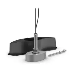
PANOPTIX
™
PS70-TH
INSTALLATION INSTRUCTIONS
Important Safety Information
WARNING
See the Important Safety and Product Information guide in the chartplotter, fishfinder, or sonar module product
box for product warnings and other important information.
You are responsible for the safe and prudent operation of your vessel. Sonar is a tool that enhances your
awareness of the water beneath your boat. It does not relieve you of the responsibility of observing the water
around your boat as you navigate.
To prevent leaks, you must apply marine sealant to the water path to ensure a tight, waterproof seal between
the transducer and hull. Immediately check for leaks after you put the vessel in the water.
CAUTION
Failure to install and maintain this equipment in accordance with these instructions could result in damage or
injury.
To avoid possible personal injury, always wear safety goggles, ear protection, and a dust mask when drilling,
cutting, or sanding.
For the best possible performance and to avoid potential injury, damage to the device, or damage to your vessel,
installation by a qualified marine installer is recommended.
NOTICE
To obtain the best performance and to avoid damage to your boat, you must install the transducer according
to these instructions. Read all installation instructions before proceeding with the installation. If you experience
difficulty during the installation, contact Garmin
®
Support.
When drilling or cutting, always check what is on the opposite side of the surface to avoid damaging the vessel.
When mounting the transducer with the fairing block, you must use the included anti-rotation bolt. Failure to do
so could result in the transducer rotating while the boat is moving and could cause damage to your vessel.
To prevent overheating and interference, do not install the transducer near the engine, in the engine room, or in
another hot location.
To prevent damage to the cable and the transducer, do not use the cable to pick up or pull the transducer and
do not strike the transducer lens.
To prevent permanent damage to the surface of the transducer, do not use solvents such as mineral spirits,
acetone, Methyl Ethyl Ketone (MEK), or similar products when cleaning. Do not use a power sander or pressure
washer to clean the transducer.
Software Update
You must update the Garmin chartplotter software when you install this device. For instructions on updating the
software, see your chartplotter owner's manual at support.garmin.com.
GUID-20571BB4-6748-4763-A557-D42CED793D6D v2
September 2024

Tools Needed
• Drill
• 3mm (
1
/
8
in.) drill bit
• 18mm wrench or adjustable wrench
• 46 mm (1
13
/
16
in.) wrench or adjustable wrench suitable for nuts up to 50 mm (2 in.)
• Marine sealant (flexible, fast-cure type, for below the waterline)
• Mild household detergent or rubbing alcohol
• Sandpaper
• Masking tape
• Waterproof electrical tape
• Wax
• Grommets (optional)
• Water-based anti-fouling paint (optional)
These additional items are needed depending on the installation.
For mounting in a cored fiberglass hull:
• 18 mm (
11
/
16
in.) drill bit
• 42mm (1
5
/
8
in.) spade bit or hole saw
• Marine-grade epoxy resin for fiberglass
For mounting in a non-cored fiberglass hull:
• 13 mm (
1
/
2
in.) drill bit
• 33mm (1
5
/
16
in.) spade bit or hole saw
For mounting in a metal hull:
• File
• 16 mm (
5
/
8
in.) drill bit
• 38mm (1
1
/
2
in.) hole saw
For installations using a fairing block:
• Bandsaw
• Rasp or power tool
2
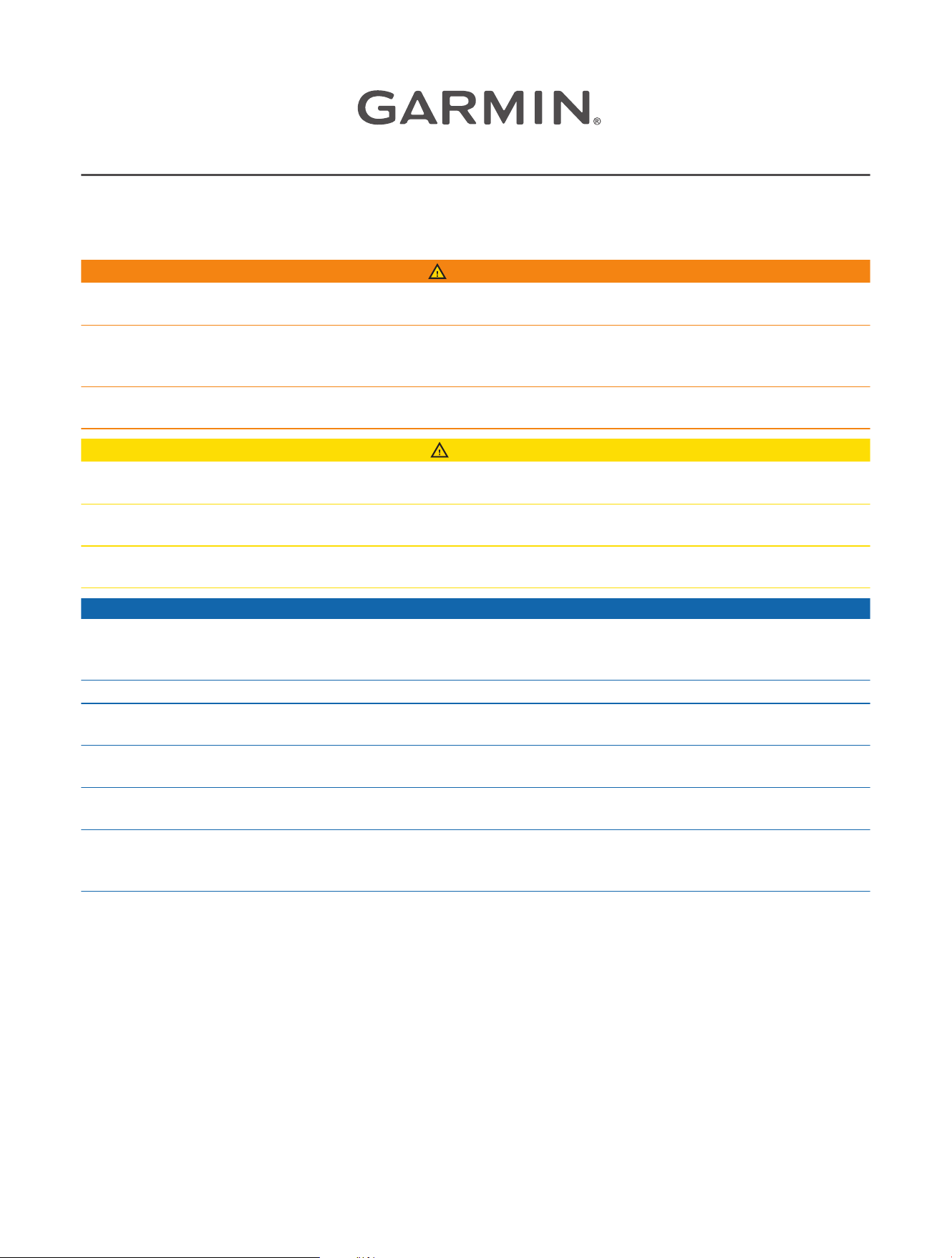
Mounting Location Considerations
When installed according to these instructions, this transducer is compatible with cored fiberglass, non-cored
fiberglass, and metal hull types.
You can install this transducer using the included fairing block in a hull location with a deadrise angle of 20
degrees or less, or you can install it in a dedicated pocket in the hull.
• On outboard and sterndrive vessels , the transducer should be mounted in front of and close to the engine
or engines.
• On inboard vessels , the transducer should be mounted in front of and far away from the engine propeller
and shaft.
• On step-hull vessels , the transducer should be mounted in front of the first step.
• On full-keel vessels , the transducer should be mounted to aim at the bow, parallel to the centerline.
• On fin-keel vessels , the transducer should be mounted from 25 to 75cm (from 10to 30in.) in front of the
keel and a maximum of 10cm (4in.) to the side of the centerline.
• On vessels with displacement hulls , the transducer should be mounted approximately
1
/
3
aft of the
waterline length of the vessel from the bow, and from 150 to 300mm (from 6 to 12in.) to the side of the
centerline.
• The transducer should not be mounted behind strakes, struts, fittings, water intake or discharge ports, or
anything that creates air bubbles or causes the water to become turbulent.
The transducer must be in clean (non-turbulent) water for optimal performance.
• The transducer should not be mounted in a location where it might be jarred when launching, hauling, or
storing.
• On single-drive boats, the transducer must not be mounted in the path of the propeller.
The transducer can cause cavitation that can degrade the performance of the boat and damage the propeller.
• On twin-drive boats, the transducer should be mounted between the drives, if possible.
Deadrise Angle
The deadrise angle is the measurement of the angle between a
horizontal line and the outer hull at a single point.
Before cutting the fairing block and drilling any holes in the hull, you must
measure the deadrise angle at the installation location with a smartphone
application, an angle finder, a protractor, or a digital level. You can also
ask your boat manufacturer for the deadrise of a specific point on your
boat hull.
NOTE: Your vessel's hull may have several deadrise angles depending
on the hull shape. Be sure to measure the deadrise angle at the selected
installation location.
3
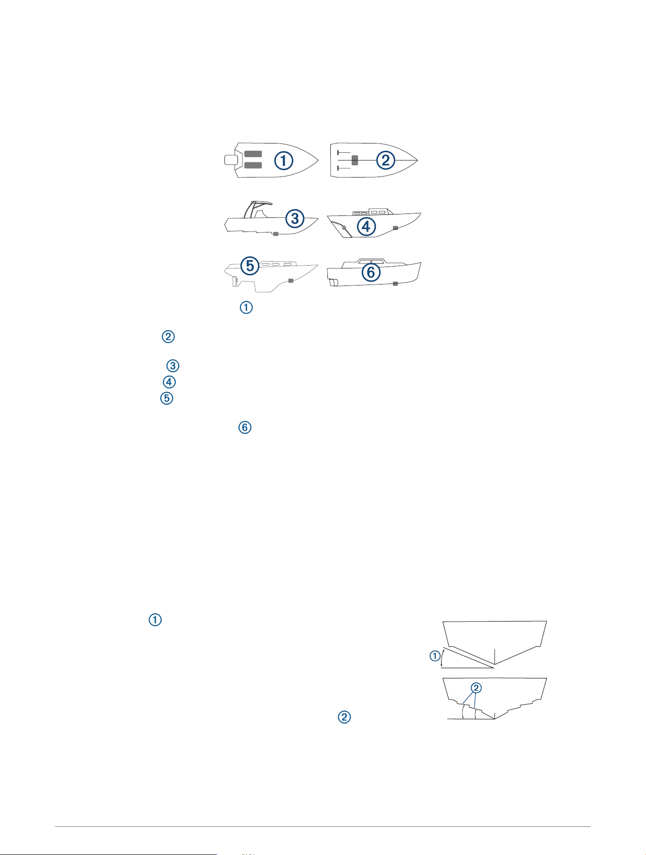
Cutting the Fairing Block
CAUTION
To avoid possible personal injury, always wear safety goggles, ear protection, and a dust mask when drilling,
cutting, or sanding.
NOTICE
The arrows on the fairing block must point to the front of the vessel.
To prevent exceeding the maximum deadrise angle of 20 degrees, do not cut into the maximum cut line
indicator on the fairing block.
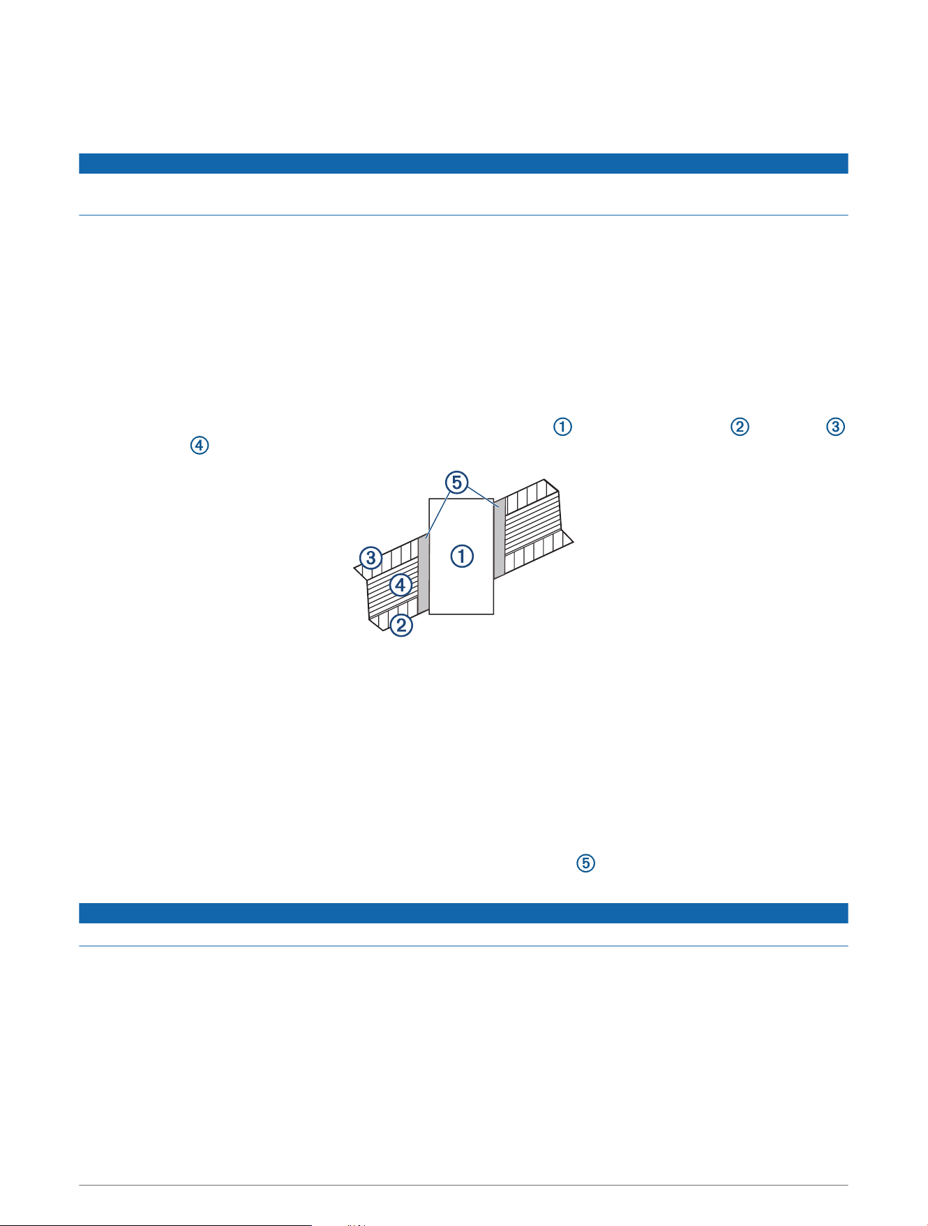
The fairing block aligns the transducer parallel to the waterline when mounting on an angled hull surface. You
must measure the deadrise angle of your boat hull to mount the transducer at the correct angle.
1 Using wood screws, attach the fairing block to a piece of wood .
The wood becomes a cutting guide for the fairing block.
2 Measure the deadrise angle of the hull at the mounting location (Deadrise Angle, page3).
3 Tilt your band saw table to match the deadrise angle, and secure the cutting fence.
4 Position the fairing block on the table so the cutting guide rests against the fence and the angle matches the
angle of the mounting location.
After installation, the arrows on the fairing block must point to the front of the vessel so the transducer
aligns with the vessel heading.
5 Adjust the cutting fence to divide the fairing into approximately equal parts, so that after cutting, the fairing
block measures between 6 and 12 mm (
1
/
4
and
1
/
2
in.) at its thinnest dimension.
Do not cut into the maximum cut line indicator on the fairing block.
6 Cut the fairing block.
7 Using a rasp or power tool, shape the fairing block to the hull as precisely as possible.
8 Use the remaining section of the fairing block as the backing block inside the hull.
4
Preparing the Hull
Preparing a Cored Fiberglass Hull
NOTICE
You must use the included anti-rotation bolt. Failure to do so could result in the transducer rotating while the
boat is moving and could cause damage to your vessel.
Before you drill holes in the hull, you should cut the fairing block (Cutting the Fairing Block, page4).
1 Select a mounting location without surface irregularities or obstructions.
2 Using the faring block as a template, mark the locations of the stem hole and anti-rotation bolt hole.
The arrows on the fairing block and transducer must point to the front of the vessel so the transducer aligns
with the vessel heading.
3 From outside the hull, drill a 3mm (
1
/
8
in.) pilot hole at the stem hole location completely through the hull
perpendicular to the water surface.
4 Place masking tape over the pilot hole and surrounding area outside the hull to reduce cracking of the gel
coat.
5 Use a 42 mm (1
5
/
8
in.) spade bit or hole saw to cut the stem hole through the outer skin , inner skin ,
and the core perpendicular to the water surface.
TIP: Running the hole saw in reverse helps to prevent damage to the fiberglass gel coat.
6 Remove the plug of core material from the hole.
7 Sand and clean the inner skin, core, and outer skin around the hole.
8 Test fit the transducer to verify the marked location of the anti-rotation bolt hole.
If the marked location does not align with the anti-rotation bolt hole on the transducer, mark the new
location.
9 Use a 18 mm (
11
/
16
in.) drill bit to drill the anti-rotation bolt hole completely through the hull perpendicular to
the water surface.
10 Sand and clean the area around the holes to remove dust particles.
11 Seal the exposed inner core with marine grade fiberglass epoxy resin and allow it to cure before securing
the transducer in the hull.
NOTICE
You must carefully seal the core to protect against water seepage.
5

Preparing a Non-Cored Fiberglass Hull
NOTICE
You must use the included anti-rotation bolt. Failure to do so could result in the transducer rotating while the
boat is moving and could cause damage to your vessel.
Before you drill holes in the hull, you should cut the fairing block (Cutting the Fairing Block, page4).
1 Select a mounting location without surface irregularities or obstructions.
2 Using the faring block as a template, mark the locations of the stem hole and anti-rotation bolt hole.
The arrows on the fairing block and transducer must point to the front of the vessel so the transducer aligns
with the vessel heading.
3 From outside the hull, drill a 3mm (
1
/
8
in.) pilot hole at the stem hole location perpendicular to the water
surface.
4 Place masking tape over the pilot hole and surrounding area outside the hull to reduce cracking of the gel
coat.
5 Cut a hole in the tape over the pilot hole.
6 Use a 33 mm (1
5
/
16
in.) spade bit or hole saw to cut the stem hole perpendicular to the water surface.
7 Test fit the transducer and verify the marked location of the anti-rotation bolt hole.
If the marked location does not align with the anti-rotation bolt hole on the transducer, mark the new
location.
8 Use a 13 mm (
1
/
2
in.) drill bit to drill the anti-rotation bolt hole perpendicular to the water surface.
9 Sand and clean the inside of the holes and the area around the holes.
Preparing a Metal Hull
NOTICE
You must use the included anti-rotation bolt. Failure to do so could result in the transducer rotating while the
boat is moving and could cause damage to your vessel.
Before you drill holes in the hull, you should cut the fairing block (Cutting the Fairing Block, page4).
1 Select a mounting location without surface irregularities or obstructions.
2 Using the faring block as a template, mark the locations of the stem hole and anti-rotation bolt hole.
The arrows on the fairing block and transducer must point to the front of the vessel so the transducer aligns
with the vessel heading.
3 From outside the hull, drill a 3mm (
1
/
8
in.) pilot hole through the hull at the stem hole location perpendicular
to the water surface.
4 Use a 38 mm (1
1
/
2
in.) hole saw to cut the stem hole perpendicular to the water surface.
5 Test fit the transducer and verify the marked location of the anti-rotation bolt hole.
If the marked location does not align with the anti-rotation bolt hole on the transducer, mark the new
location.
6 Use a 16 mm (
5
/
8
in.) drill bit to drill the anti-rotation bolt hole perpendicular to the water surface.
7 Sand and clean the inside of the holes and the area around the holes.
6

Preparing the Hull Pocket
You must drill the transducer stem hole in the hull pocket. The anti-rotation bolt and fairing block are not used
when installing the transducer in a hull pocket.
1 Test fit the transducer in the hull pocket.
The arrow on the transducer must point to the front of the vessel so the transducer aligns with the vessel
heading.
2 Drill a 3mm (
1
/
8
in.) pilot hole at the location for the stem hole.
3 Place masking tape over the pilot hole and the surrounding area to reduce cracking the fiberglass gel coat.
4 Cut out the tape over the hole.
5 Use a 33 mm (1
5
/
16
in.) spade bit or hole saw to cut the stem hole.
TIP: Running the hole saw in reverse helps prevent damage to the fiberglass gel coat.
6 Sand and clean the area around the hole.
Installing the Transducer
Applying Marine Sealant to a Thru-Hull Transducer
You must apply marine sealant to the water path between components to ensure a tight, waterproof seal.
Apply marine sealant between these components.
• Fairing block and hull
• Fairing block and transducer
• Fairing block and anti-rotation bolt cap
• Holes for bolts and transducer cable stem
• Stem and hull nut
• Bushings, stem, and hull
• Transducer and hull pocket
7
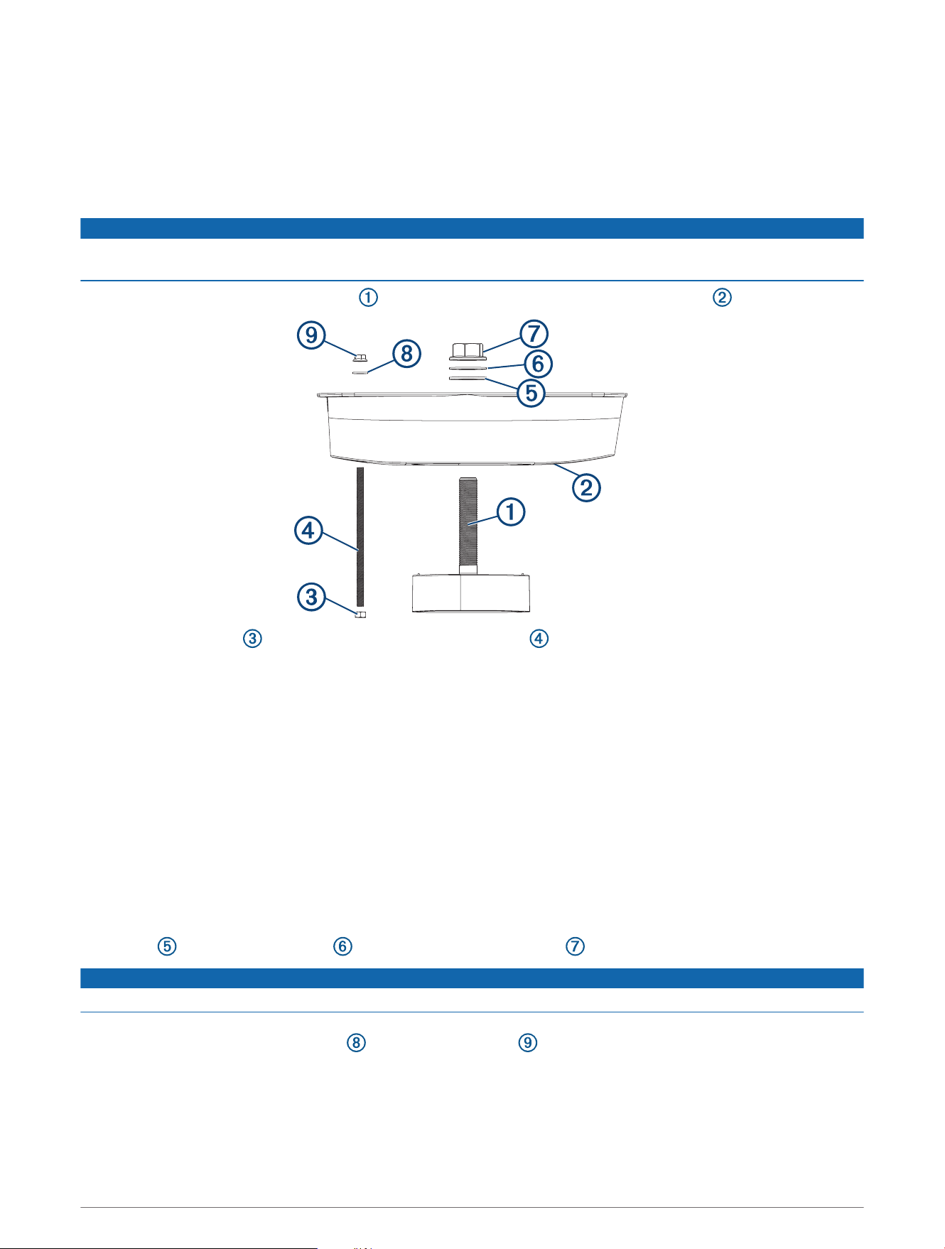
Installing the Transducer in a Fiberglass Hull
When installing the transducer in a cored fiberglass hull, you must cut the fairing block (Cutting the Fairing Block,
page4) and seal the exposed areas of the inner core with marine-grade fiberglass epoxy resin and allow it to
cure before installing the transducer (Preparing a Cored Fiberglass Hull, page5).
It is recommended that two installers complete these instructions, with one positioned outside the boat and one
inside the boat.
NOTICE
You must apply marine sealant where necessary to prevent seepage and corrosion (Applying Marine Sealant to a
Thru-Hull Transducer, page7).
1 Push the transducer cable and stem through the bottom half of the cut fairing block .
2 Secure the M12 nut to the bottom of the anti-rotation bolt until no more than two threads are exposed
between the M12 nut and the bottom of the fairing block.
3 Insert the anti-rotation bolt into the bottom half of the cut fairing block.
4 Apply marine sealant to the surface of the bottom half of the fairing block where it contacts the hull.
5 From outside the hull, push the transducer cable, stem, and anti-rotation bolt through the mounting holes in
the hull, and push the bottom half of the fairing block firmly against the outside hull.
The fairing block and transducer must be parallel to the keel. The arrows on the fairing block and transducer
must point to the front of the vessel so the transducer aligns with the vessel heading.
6 From inside the hull, pull the transducer cable, stem, and anti-rotation bolt through the top half of the fairing
block.
7 Apply marine sealant to the surface of the top half of the fairing block where it contacts the hull.
8 Place the top half of the fairing block firmly against the inside hull.
9 Apply the included anti-seize compound to the exposed stem and anti-rotation bolt.
10 Use a 46mm (1
13
/
16
in.) wrench or adjustable wrench to secure the stem with the included rubber 34mm
washer , nylon 34mm washer , and M33 flanged hex hull nut .
NOTICE
To prevent damage, do not over-tighten the nut.
11 Use an 18mm wrench or adjustable wrench to secure the top half of the fairing block to the anti-rotation bolt
with the included 13.4mm washer and flanged M12 nut .
NOTE: Do not over-tighten the nut.
12 Place the anti-rotation bolt cap over the end of the anti-rotation bolt on the underside of the fairing, and cover
the cap with a smooth coating of sealant.
8
13 Apply sealant around the stem and anti-rotation bolt.
14 Before the sealant hardens, use a mild household detergent or rubbing alcohol to remove all excess sealant
on the outside of the fairing block and exterior hull to ensure smooth water flow over the transducer.
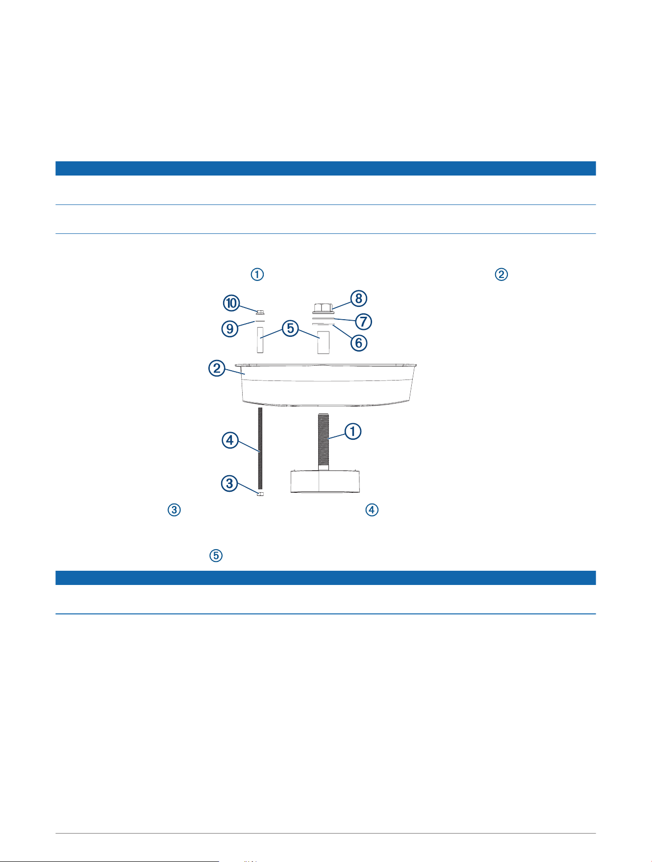
Installing the Transducer in a Metal Hull
You must cut the fairing block (Cutting the Fairing Block, page4) and prepare the hull (Preparing a Metal Hull,
page6) before installing the transducer.
NOTICE
When installing the transducer in a metal hull, you must use the included isolation bushings and make sure the
transducer is completely isolated from the hull to prevent damage from electrolytic corrosion.
You must apply marine sealant where necessary to prevent seepage and corrosion (Applying Marine Sealant to a
Thru-Hull Transducer, page7).
It is recommended that two installers complete these instructions, with one positioned outside the boat and one
inside the boat.
1 Insert the transducer cable and stem through the bottom half of the cut fairing block .
2 Secure the M12 nut to the bottom of the anti-rotation bolt until no more than two threads are exposed
between the M12 nut and the bottom of the fairing block.
3 Insert the anti-rotation bolt into the bottom half of the cut fairing block.
4 Place the isolation bushings on the anti-rotation bolt and stem.
NOTICE
You must use the included isolation bushings to prevent damage and corrosion to the transducer and metal
hull.
5 Apply marine sealant to the surface of the bottom half of the fairing block where it contacts the hull.
6 From outside the hull, push the transducer cable, stem, and anti-rotation bolt through the mounting holes in
the hull, and push the bottom half of the fairing block firmly against the outside hull.
The fairing block and transducer must be parallel to the keel. The arrows on the fairing block and transducer
must point to the front of the vessel so the transducer aligns with the vessel heading.
7 From inside the hull, pull the transducer cable, stem, and anti-rotation bolt through the top half of the fairing
block.
8 Apply marine sealant to the surface of the top half of the fairing block where it contacts the hull.
9 Place the top half of the fairing block firmly against the inside hull.
10 Apply the included anti-seize compound to the exposed stem and anti-rotation bolt.
9
11 Use a 46mm (1
13
/
16
in.) wrench or adjustable wrench to secure the stem with the included rubber 34mm
washer , nylon 34mm washer , and M33 flanged hex hull nut .
NOTICE
To prevent damage, do not over-tighten the nut.
12 Use an 18mm wrench or adjustable wrench to secure the top half of the fairing block to the anti-rotation bolt
with the included 13.4mm washer and flanged M12 nut .
NOTICE
To prevent damage, do not over-tighten the nut.
13 Place the anti-rotation bolt cap over the end of the anti-rotation bolt on the underside of the fairing, and cover
the cap with a smooth coating of sealant.
14 Apply sealant around the stem and anti-rotation bolt.
15 Before the sealant hardens, use a mild household detergent or rubbing alcohol to remove all excess sealant
on the outside of the fairing block and exterior hull to ensure smooth water flow over the transducer.
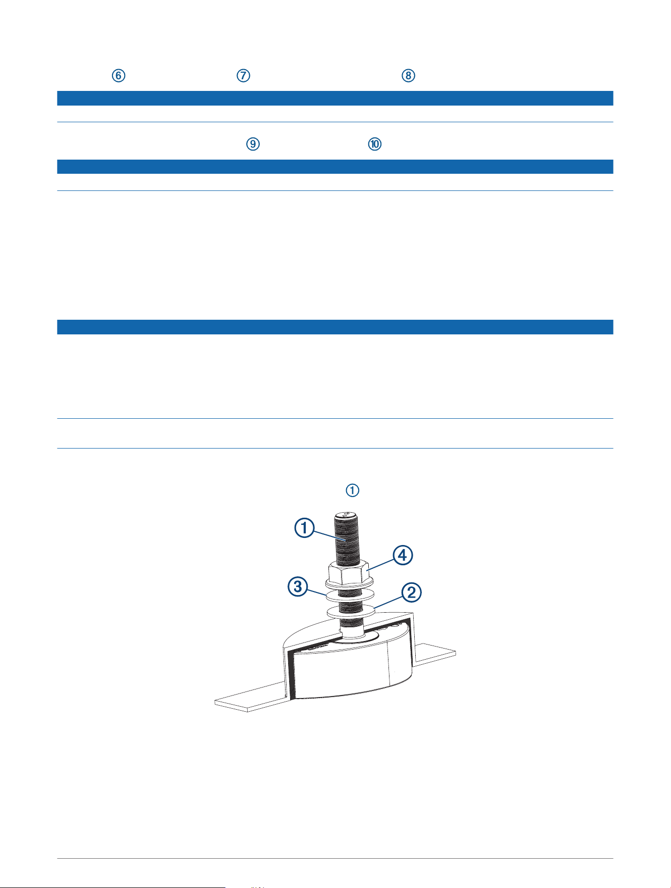
Installing the Transducer in a Hull Pocket
You must prepare the pocket before you install the transducer (Preparing the Hull Pocket, page7).
NOTICE
When installing the transducer in a pocket made of a metal material, you must fabricate a non-metal spacer
to separate the top of the transducer from the pocket material. You must allow space around all sides of the
transducer and apply marine sealant to prevent contact with the metal pocket material. Point features on top
of the transducer housing must engage the spacer to prevent the transducer from rotating and contacting the
hull pocket material. You must make sure there is no contact between the transducer and any metal material, to
prevent hull damage caused by electrolytic corrosion.
You must apply marine sealant where necessary to prevent seepage and corrosion (Applying Marine Sealant to a
Thru-Hull Transducer, page7).
It is recommended that two installers complete these instructions, with one positioned outside the boat and one
inside the boat.
1 Apply the included anti-seize compound to the threads on the transducer stem.
2 Apply sealant to the stem and the surfaces of the transducer.
3 From outside the hull, push the transducer cable and stem through the mounting hole in the hull pocket, and
push the transducer firmly against the outside of the hull.
The arrow on the transducer must point to the front of the vessel so the transducer aligns with the vessel
heading.
10

4 From inside the hull, use a 46mm (1
13
/
16
in.) wrench or adjustable wrench to secure the stem with the
included rubber 34mm washer , nylon 34mm washer , and M33 flanged hex nut .
NOTICE
To prevent damage, do not over-tighten the nut.
5 Before the sealant hardens, use a mild household detergent or rubbing alcohol to remove all excess sealant
on the exterior hull to ensure smooth water flow over the transducer.
Routing and Connecting the Transducer Cable
NOTICE
To prevent damage to the cable and the transducer, do not use the cable to pick up or pull the transducer.
Do not cut or splice the transducer cable. Cutting the transducer cable may void your warranty.
You must connect the transducer cable to a power source and a compatible Garmin chartplotter.
1 Route the transducer cable to the power source and a compatible Garmin chartplotter while taking these
precautions.
• Route the cable away from other wiring and the engine(s) to prevent possible interference with the sonar
signal.
• Route the cable so it is not pinched by other equipment
• Use grommets to protect the cable if it passes through the bulkhead or other parts of the boat
• Use black electrical tape to secure the cable where necessary to protect it from damage
2 Connect the power cable directly to the battery.
If it is necessary to extend the power cable, the appropriate gauge of wire must be used for the length of the
extension:
• 12AWG (3.31mm²) extension wire, up to 4.6m (15ft.)
• 10AWG (5.26mm²) extension wire, up to 7m (23ft.)
• 8AWG (8.36mm²) extension wire, up to 11m (36ft.)
3 Connect the Garmin BlueNet
™
cable to an open port on a Garmin BlueNet chartplotter or the Garmin BlueNet
20 switch, and turn the locking ring clockwise to tighten it.
NOTE: You can use a Garmin Marine Network adapter
1
to connect the transducer to a Garmin Marine
Network chartplotter.
NOTE: If necessary, you can extend the network cable using a Garmin BlueNet cable and Garmin BlueNet
coupler, available at buy.garmin.com or from your Garmin dealer.
1
If a Garmin Marine Network adapter cable is not supplied in the product box, you can purchase one from your local Garmin dealer (part number 010-12531-01)
or go to garmin.com/accessories/GMNAdapterCable.
11
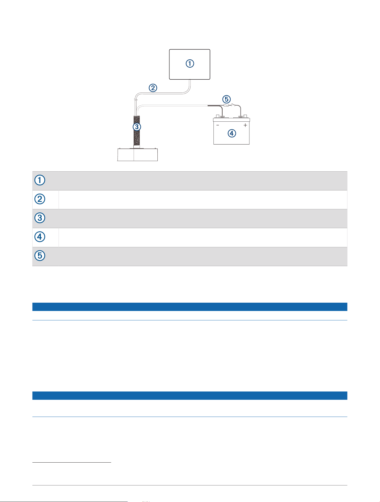
Connection Diagram
Chartplotter
Garmin BlueNet cable (built into the transducer housing)
Panoptix PS70-TH transducer
Power source
Fuse (kit included) and optional switch
2
Maintenance
Testing the Installation
NOTICE
You should check your boat for leaks before you leave it in the water for an extended period of time.
Because water is necessary to carry the sonar signal, the transducer must be in the water to work properly. You
cannot get a depth or distance reading when out of the water. When you place your boat in the water, check for
leaks around any screw holes that were added below the water line.
Anti-Fouling Paint
To prevent corrosion on metal hulls and to slow the growth of organisms that can affect a vessel's performance
and durability on both metal and fiberglass hulls, you should apply a water-based anti-fouling paint to the
transducer and to the hull of your vessel every six months or at the beginning of each boating season.
NOTICE
Never apply ketone-based anti-fouling paint to the transducer or to your vessel. Ketones attack many types of
plastic and could damage or destroy your transducer.
2
The fuse is included and is recommended. A power switch is optional. The chartplotter automatically turns the transducer on and off.
12
Cleaning the Transducer
CAUTION
To avoid possible transducer damage or personal injury, use care when cleaning the transducer, particularly
when attempting to remove severe fouling.
NOTICE
To prevent permanent damage to the surface of the transducer, do not use solvents such as mineral spirits,
acetone, Methyl Ethyl Ketone (MEK), or similar products when cleaning. Do not use a power sander or pressure
washer to clean the transducer.
Aquatic fouling accumulates quickly and can reduce your device's performance.
1 Remove the fouling with a soft cloth and mild detergent.
2 If the fouling is severe, use a non-metallic scouring pad or putty knife to remove growth.
3 Wipe the transducer dry.
Specifications
Dimensions (W × H)
Transducer: 114× 216mm (4.5 × 8.5in.)
Fairing: 133 × 568mm (5.25 × 22.35in.)
Operating temperature From 0° to 40°C (from 32° to 104°F)
Storage temperature From -40° to 70°C (from -40° to 158°F)
Frequency 200kHz
Input voltage From 10 to 35Vdc
Fuse 7.5A, included
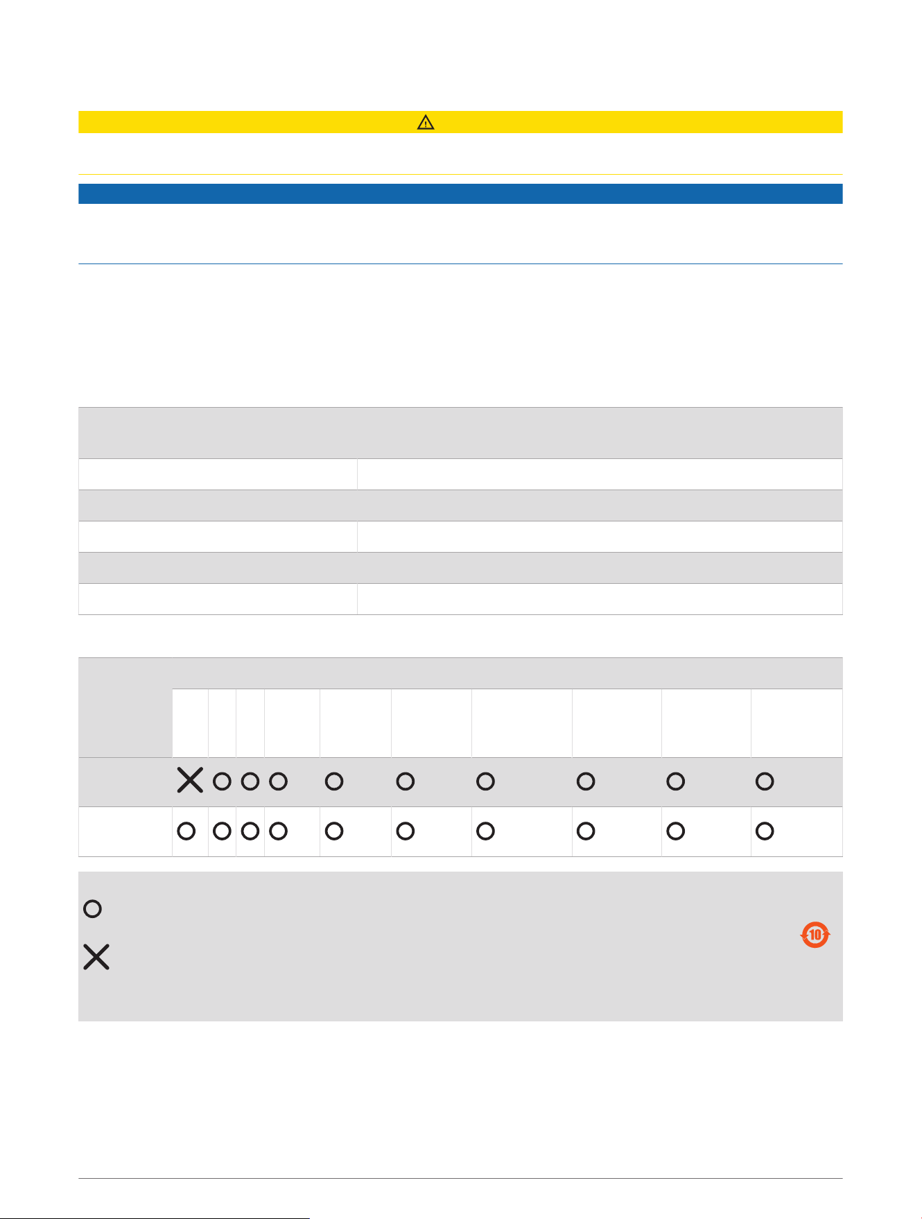
物質宣言
部件名称
有毒有害物质或元素
铅 汞 镉 六价铬 多溴联苯
多溴二苯
醚
邻苯二甲酸
二(2-乙基己)
酯
邻苯二甲酸
丁苄酯
邻苯二甲酸
二丁酯
邻苯二甲酸
二异丁酯
塑料和橡胶
零件
塑料和橡胶
零件
本表格依据 SJ/T11364 的规定编制。
: 代表此种部件的所有均质材料中所含的该种有害物质均低于
(GB/T26572) 规定的限量
: 代表此种部件所用的均质材料中, 至少有一类材料其所含的有害物质高于
(GB/T26572) 规定的限量
* 该产品说明书应提供在环保使用期限和特殊标记的部分详细讲解产品的担保使用条件。
产品
13

連絡地址
製造銷售:台灣國際航電股份有限公司
聯絡地址:新北市汐止區樟樹二路 68 號
電 話:(02)2642-8999
客服專線:(02)2642-9199
© 2023 Garmin Ltd. or its subsidiaries
Garmin
®
and the Garmin logo are trademarks of Garmin Ltd. or its subsidiaries, registered in the USA and other countries. Panoptix
™
is a trademark of Garmin Ltd. or its
subsidiaries. These trademarks may not be used without the express permission of Garmin.
Garmin Corporation
© 2023 Garmin Ltd. or its subsidiaries
support.garmin.com
