To Reduce The Risk Of Injury, User Must Read And
Understand Operator’s Manual. Save These Instructions For Future Reference.
260-9476
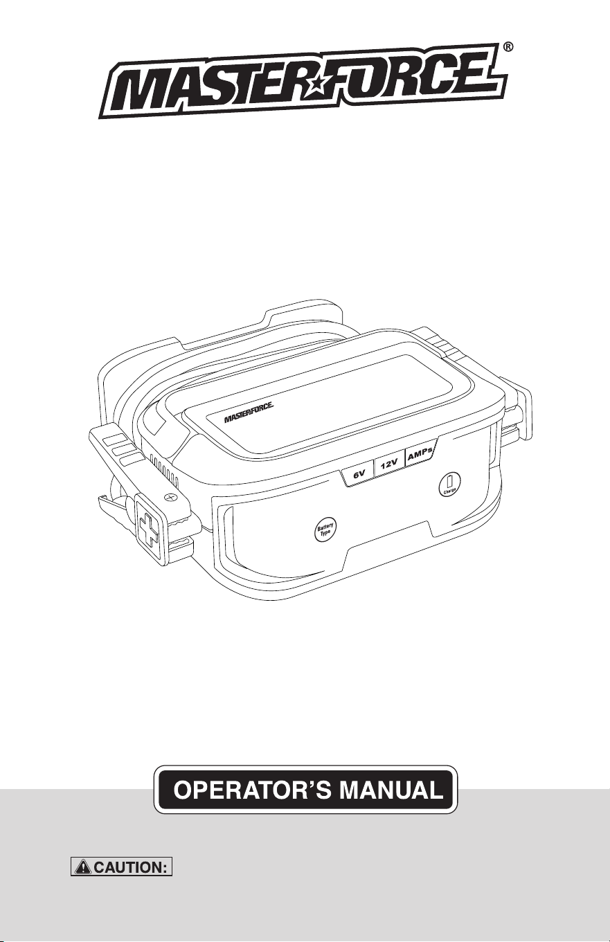
6V/12V 15A Battery Charger

TABLE OF CONTENTS
Safety Instructions ...............................................................................
Page 4
Product Introduction.............................................................................
Page 4
AC Electrical Connections....................................................................
Page 5
Plugging It In ...................................................................................
Page 5
Using An Extension Cord ...............................................................
Page 5
Charger Location ............................................................................
Page 6
Battery Preparation ........................................................................
Page 6
Charging A Battery Installed In Vehicle .........................................
Page 6
Charging A Battery Removed From Vehicle ..................................
Page 7
Charger Controls ............................................................................
Page 7
Battery Indicators ...........................................................................
Page 8
Charge The 12V Battery .................................................................
Page 8
Charge The 6V Battery ...................................................................
Page 8
Memory Function & Auto Charge ...................................................
Page 9
Charge Rate Selection ...................................................................
Page 9
Charge Features .............................................................................
Page 9
Preparing To Charge ............................................................................
Page 6
Battery Charging Times ......................................................................
Page 9
Charging The Battery ...........................................................................
Page 8
Troubleshooting Fault Codes ............................................................
Page 10
Maintenance And Care ......................................................................
Page 10
Limited Warranty ................................................................................
Page 15
Charger Controls ..................................................................................
Page 7

CAUTION:
WARNING:
DANGER:
SAFETY INFORMATION
Page 3
WARNING:
Be sure to read and understand all safety instructions in this
manual, including all safety alert symbols such as “DANGER”, “WARNING” and
“CAUTION”, before using this power tool. Failure to follow all instructions listed
below may result in electric shock, fire and/or serious personal injury.
Failure to obey this warning WILL result in death or serious injury
to yourself or to others. Always follow the safety precautions to reduce the risk of
fire, electric shock and personal injury.
Failure to obey this safety warning MAY result in personal injury
to yourself or others or property damage. Always follow the safety precautions to
reduce the risk of fire, electric shock and personal injury.
Failure to obey this safety warning CAN result in death or serious
injury to yourself or to others. Always follow the safety precautions to reduce the
risk of fire, electric shock and personal injury.
SYMBOL MEANING
The purpose of safety symbols is to attract our attention to possible dangers. The safety
symbols, and the explanations with them, deserve your careful attention and under-
standing. The symbol warnings do not by themselves enliminate any danger. The instruc-
tions and warnings given are no substitutes for proper accident prevention measures.
SAFETY ALERT SYMBOL: Indicates DANGER, WARNING, OR CAUTION.
May be used in conjuntion with other symbols or pictographs.

Page 4
1. SAFETY INSTRUCTIONS
IMPORTANT SAFETY
WARNING:
Handling the cord on
this product or objects associated with the
use of this product may expose you to
lead. Wash hands after handling.
Read all instructions and cautions printed
on the battery charger, battery and
vehicle or equipment using battery.
Use the charger for charging batteries
only such as those used in cars, trucks,
motorcycles, boats, etc. It is not intended
to supply power to a low-voltage electri-
cal system or to charge dry-cell batteries
commonly used in household appliances
such as radios, toys, camera, etc.
Charging dry-cell batteries may cause
them to burst and cause injury to persons
and damage to property.
Use of an attachment not recommended
by the battery charger manufacturer may
result in the risk of fire or electrical shock.
Do not disassemble charger. Take it to a
qualified service professional if service or
repair is required. Incorrect assembly
may result in fire or electrical shock.
To reduce risk of electrical shock, unplug
the charger from the outlet before
attempting any maintenance or cleaning.
Do not expose charger to rain or snow.
Do not expose the product to heat sourc-
es such as direct sunlight or other heating
elements.
Never charge a frozen or defective battery.
Never touch the battery clamps together
when the charger is on. This may cause
a spark.
Never operate a charger if it has received
a hard blow, been dropped or otherwise
damaged. Take it to a qualified profes-
sional for inspection.
Never pull out the plug by the cord when
unplugging the charger as this may
cause damage to the cord or plug.
Keep away from children, as electrical
devices are not toys.
Before using your battery charger or
maintainer, please read and understand this
user manual. Any incorrect operation or
misuse may damage the equipment and/or
create hazardous conditions for the user.
PERSONAL SAFETY
Make sure that someone is within range
of your voice to come to your aid if
needed while you work with or are near a
battery.
Wear goggles, gloves and other protec-
tive clothing when working with batteries.
Avoid touching your eyes while working
with a battery.
Have plenty of fresh water and soap
nearby for use in case battery acid
contacts your eyes, skin or clothing. If
this happens, wash immediately with
soap and water then get medical
attention.
Never smoke or allow an open spark or
flame in the vicinity of the battery or
engine. Batteries generate explosive
gases.
Take care not to drop any metal tool or
object onto the battery. This may result
in a spark or short circuit across the
battery or another electrical device that
may cause an explosion.
Avoid wearing metal objects such as
watches or rings while working with a
battery-short circuit risk!
Never overcharge a battery.
Always operate the battery charger in an
open, well-ventilated area.
2. PRODUCT INTRODUCTION
The innovative 2/8/15 Amp charger can
easily be set at 2, 8, 15 Amp charge rate for
different battery capacities. The charger
offers correct charging for most type of
batteries. Electronic protections built into
the charger, users can feel confident that
their batteries are being charged optimally
and automatically. Products suitable for
household use.
Maintainer: 2 Amp battery maintainer option
for use while storing your vehicles without
having to disconnect your battery. Simply
connect the cables, choose 2Amp charging
current.
1.1
1.2
1.3
1.4
1.5
1.6
1.7
1.9
1.10
1.11
1.12
1.13
1.14
1.15
1.16
1.17
1.18
1.19
1.20
1.21
FEATURES
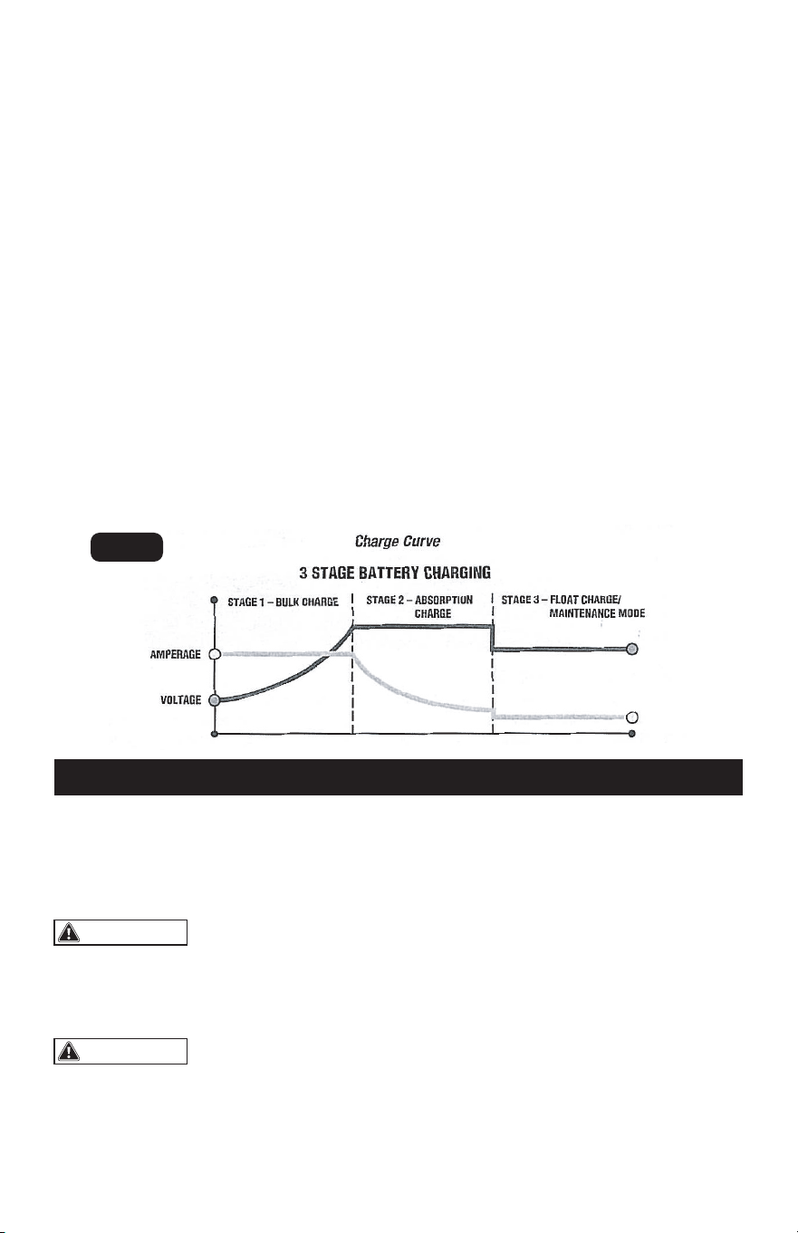
Three-Stage Battery Charging
Page 5
battery reaches a maximum safe prede-
termined voltage, the charger will auto-
matically move into Stage 2 of the
charging process.
Stage Two - Absorption Charge main-
tains the maximum possible charge at a
constant, safe, predetermined voltage.
During this phase, the charging voltage
remains constant, while the actual
charging current is reduced to allow for
the maximum proper internal chemical
energy transfer. At the end of Stage 2,
the charger will automatically move into
Stage 3 charge mode.
Stage Three - Float Charge - Voltage is
automatically maintained and reduced to
a predetermined level while current is
adjusted for a safe, effective battery
charge. The Automatic Float Charge
feature is ideal for maintaining a battery.
It automatically tops off battery as
needed, to keep battery fully charged all
the time.
Compatible with multiple types of batter-
ies: 6V&12V lead-acid batteries, includ-
ing Wet (Flooded), Gel, MF(mainte-
nance-free), EFB (Enhanced Flooded
Battery), AGM (Absorption Glass Mat)
batteries and 12V Lithium battery.
Multiple battery voltage and charging
current options.
Smart electronic protections including
over-voltage, over-temperature, reverse
polarity.
Stage One - Bulk Charge delivers maximum
charging amperage to "wake up" any
serviceable 6 volt or 12 volt battery. When
This manual will explain how to use the
charger safely and effectively. Please read
and follow these instructions and precautions
carefully.
s
FIG. 1
WARNING:
WARNING:
3. AC ELECTRICAL CONNECTIONS
PLUGGING IT IN USING AN EXTENSION CORD
Never alter AC cord or
plug provided. If it does not fit the outlet,
have a proper outlet installed by a qualified
electrician. Improper connection can
result in a risk of fire or electric shock.
Do not operate the
charger if it has a damaged power cord or
plug. Have the cord replaced.
The use of an extension cord is not recom-
mended. If an extension cord must be used,
follow these guidelines:
Your charger requires a 120 V AC electrical
wall outlet receptacle installed according to
local codes and ordinances.
Make sure that the pins on the charger’s
power cord fit firmly into the extension
cord and that the extension cord fits firmly
into the receptacle.
Check that the extension cord is properly
wired and in good electrical condition.
Make sure that the wire size is large
enough for its length and for the AC
ampere rating of the charger, as specified
in the chart below.
2.1
2.2
2.3
2.4
2.5
2.6
3.1
3.2
3.3

Do not expose charger to rain or snow.
Locate the charger as far away from the
battery being charged as the cables will
permit.
Be sure to position the power cord to
prevent it from being stepped on, tripped
over or damaged.
Never place charger directly above
battery being charged. Gases from the
battery will corrode and damage the
charger.
Never set a battery on top of a charger.
Always charge a battery in a well-venti-
lated area.
If it is necessary to remove battery from
vehicle to charge it, always remove
grounded terminal from battery first.
Make sure all accessories in the vehicle
are OFF in order to prevent sparks.
Be sure that the area around the battery
is well ventilated while being charged.
Clean the battery terminals. Be careful to
keep corrosion or battery acid from
getting in or around your eyes.
For batteries with removable vent caps, if
required, add distilled water to each cell
until the battery fluid reaches the level
specified by the battery manufacturer.
Do not overfill. For batteries without
removable vent caps, carefully follow the
manufacturer’s charging instructions.
Study all of the battery manufacturer’s
specific precautions and recommenda-
tions for charging and for recommended
Page 6
4. PREPARING TO CHARGE
CHARGER LOCATION
BATTERY PREPARATION
WARNING:
Battery chargers may
get hot during operation. Do not set charger
on flammable materials like carpeting,
upholstery, paper, cardboard, etc. Charger
may damage leather, plastic and rubber.
rates of charge.
Make sure that you have a 6V or 12 V
lead-acid battery and 12V lithium battery.
Determine voltage of battery by referring
to the vehicle owner’s manual. The
charger has 3 different charge rates,
select the suitable charge rate according
to the “Charge rate table”.
16 12 10
15.2
(50)
30.5
(100)
45.6
(150)
WARNING:
Use of an improper
extension cord could result in a risk of fire
and electric shock.
Minimum Recommended Extension Cord
Length of cord,
Metres (Feet)
7.6
(25)
18AWG*Size Of Cord
*AWG=American Wire Gauge
CHARGING A BATTERY
INSTALLED IN VEHICLE
Follow these steps when battery is installed in
vehicle. A spark near battery may cause a
battery explosion. To reduce the risk of a
spark near battery:
Position AC and DC cords to reduce the
risk of damage by hood, door, or moving
engine part.
Stay clear of fan blades, belts, pulleys,
and other parts than can cause injury to
persons.
Check polarity of battery posts. A positive
(POS, P, +) battery post usually has a
larger diameter than a negative (NEG, N,
-) post.
Determine which battery post is ground-
ed (connected) to the chassis. IT IS
NORMALLY THE NEGATIVE POST.
Connecting to a negative-grounded
system: Connect the positive (red) clip
from a battery charger to a positive (POS,
P, +) ungrounded post of battery.
Connect the negative (black) clip to
vehicle chassis or engine block away
from battery. Do not connect clip to
carburetor, fuel lines, or sheet-metal body
parts. Connect to a heavy gauge metal
part of the frame or engine block.
CAUTION:
A marine battery installed
in a boat must be removed and charged on
shore. To charge it on board requires
equipment specially designed for marine
use. Never allow the DC output clamps to
touch each other. This may cause a spark.
4.1
4.2
4.3
4.4
4.5
4.6
4.7
4.8
4.9
4.10
4.11
4.12
4.13
4.14
4.15
4.16
Page 7
Never allow the DC
output clamps to touch each other. This
may cause a spark.
Follow these steps when battery is removed
from vehicle. A spark near battery may cause
a battery explosion. To reduce the risk of a
spark near battery:
s
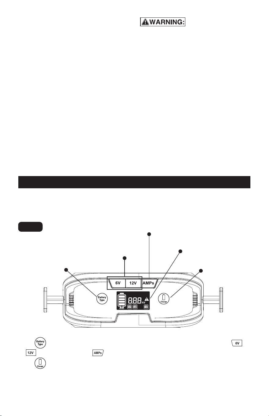
5. CHARGER CONTROLS
CHARGER CONTROLS - Front panel explanation
Battery type
selection touch key
Charging current
selection button
Battery voltage
selection button
Digital display
Confirm
touch key
CHARGING A BATTERY
REMOVED FROM VEHICLE
Touch button to select the battery type, then set the battery voltage by pressing
or button, also pressing button to set the charging current. It is necessary to
touch to confirm each selection, then it will start charging.
Fig. 2
4.17
4.18
4.19
4.20
Connecting to a positive-grounded
system: Connect the negative (black)
clip from battery charger to negative
(NEG, N, -) ungrounded post of battery.
Connect the positive (red) clip to vehicle
chassis or engine block away from
battery. Do not connect clip to carbure-
tor, fuel lines, or sheet-metal body parts.
Connect to a heavy gauge metal part of
the frame or engine block.
Plug the charger AC supply cord into a
live AC power outlet.
Charge battery as outlined in OPERA-
TION INSTRUCTIONS section.
When disconnecting charger, discon-
nect AC cord, remove clip from vehicle
chassis, and then remove clip from
battery terminal.
Connect the positive (+) clamp to the
battery positive terminal
Connect the negative (-) clamp to the
battery negative terminal.
Plug the charger AC supply cord into a
live AC power outlet.
Charge battery as outlined in OPERAT-
ING INSTRUCTIONS section.
When disconnecting chargers, always
do so in reverse sequence of connect-
ing procedure and break first connec-
tion while standing as far away from
battery as practical.
4.21
4.22
4.23
4.24
4.25
Page 8
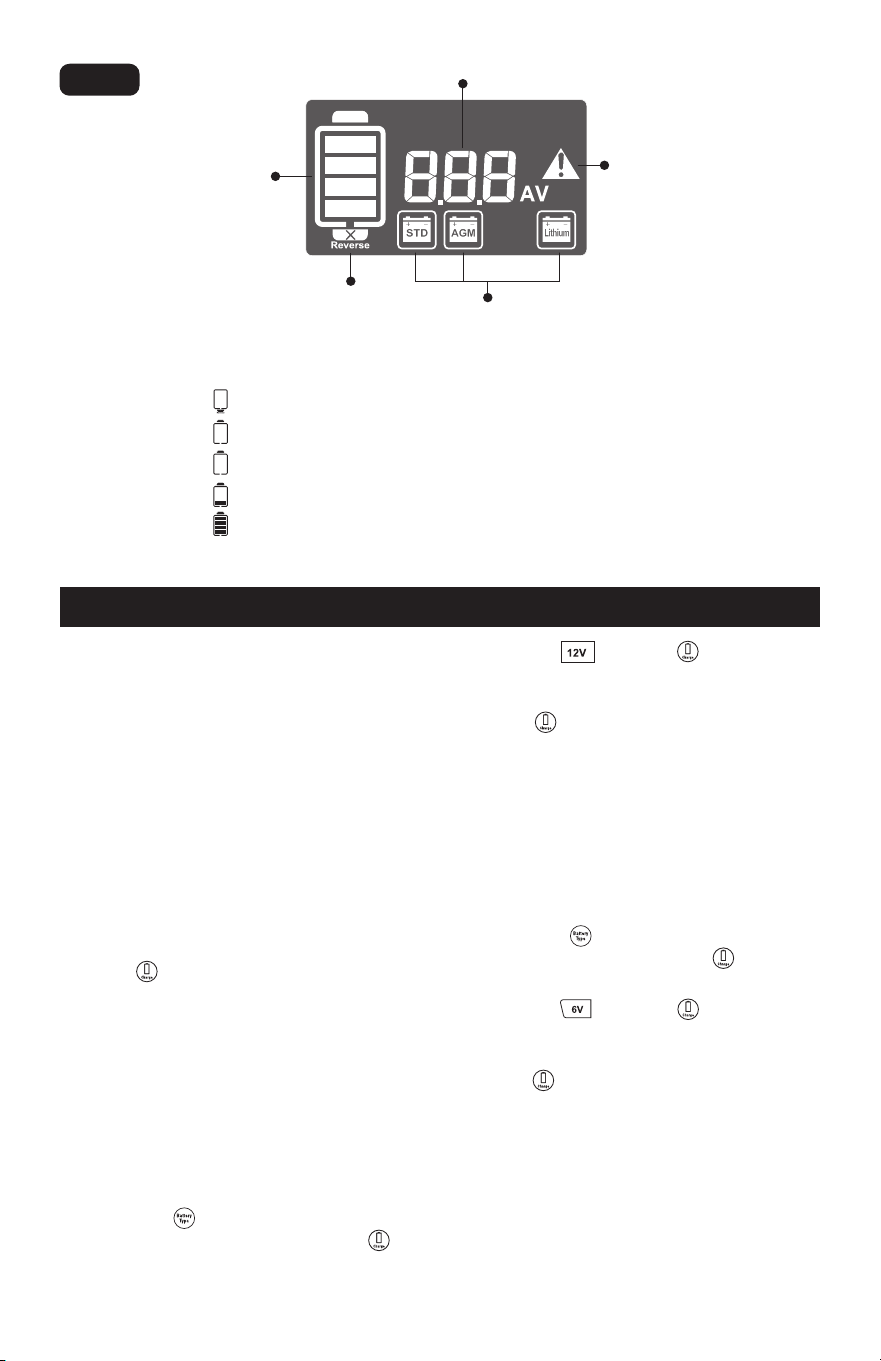
BATTERY INDICATORS
5.1 When the icon flashing, indicates the battery is reverse connection.
5.2 When the icon flashing, indicates the battery is not connected.
5.3 When the icon is on, indicates the battery is connected, but the charging is not started.
5.4 When the icon is on, indicates the battery is being charged.
5.5 When the icon is on, indicates battery is full charged.
Digital display
Fault indicator
Battery indicator
Battery type indicator
Reverse indicator
Using this battery charger is extremely
simple. The built-in microprocessor was
designed to seamlessly work with all types
of 6V or 12V lead-acid batteries, and 12 V
lithium battery.
First, prepare your battery and make output
cable and AC power connections following
the precautions and instructions described
in “PREPARING TO CHARGE.”
Once the AC cord is plugged in, the charger
display panel will light up. For first time use,
it will go into default settings as STD lead
acid battery, 12V and 8A charging current.
Use the button to start charging if you
do not need to change any settings.
If you need to change the settings on the
charger for a different battery, please use
the following operating instructions.
6. CHARGING THE BATTERY
Press the and touch to confirm your
selection.
Select the charging current you prefer, and
touch to start charging.
Note: The charging current 2A, 8A and 15A
can be set for charging, see the section of
CHARGE RATE SELECTION and BATTERY
CHARGE TIMES for reference.
CHARGE 6V BATTERY
Observe and confirm what type of battery
you connected.
Touch the and select the STD or AGM
battery type and then touch to confirm
your selection.
Press the and touch to confirm your
selection.
Select the 2A charging current and then
touch to start charging.
Note: You can only choose 2A charging
current to charge 6V battery; The battery
charger can only charge the 6V lead acid
batteries, NOT for any lithium battery.
CHARGE 12V BATTERY
Observe and confirm what type of battery
you connected.
Touch the and select the correspond-
ing battery type and then touch to
confirm your selection.
Fig. 3
6.1
6.2
6.3
6.4
6.5
6.6
6.7
6.8

Page 9
s
MEMORY FUNCTION &
AUTO CHARGE
CHARGE RATE SELECTION
This battery charger has a built-in memory
function that remembers the last used
settings. Simply connect the battery and AC
power source, and the battery charger will
begin charging automatically after 30
seconds.
Press the “AMPs” button to select desired
charge rate as follows:
8 A or 15 A Charge Rate – Use for faster
charging of small-to-large capacity automo-
tive, marine, deep cycle and farm tractor
batteries.
2 A Charge Rate - Use for charging motor-
cycle, ATV, snowmobile, personal water-
craft, garden tractor and go cart batteries.
CHARGER FEATURES
ABORTED CHARGES – If charging can’t be
completed normally, charging will be
borted. The display may show a fault code.
To reset the charger after an aborted
charge, disconnect the battery or unplug
the charger.
BATTERY DIAGNOTICS – The charger
continuously monitors battery condition
and may report certain charging failures as
fault codes. Refer to the section called
“TROUBLESHOOTING FAULT CODES” for a
complete list.
COOLING FAN OPERATION – The charger
is designed to control its high speed
cooling fan for efficient operation. Conse-
quently, it is normal for the fan to start and
stop during charging.
OVERHEAT PROTECTION – The charger is
designed to shut itself off if overheating is
detected. Once the charger cools down, it
will resume charging automatically.
7. BATTERY CHARGING TIMES
The built-in intelligent microprocessor will
continuously monitor and adjust the charger
to provide a fast, safe and efficient charge.
Note that battery charge times will vary
depending on several factors including:
Battery State – If a battery has been only
slightly discharged, it can be charged in
less than a few hours. This same battery
could take up to 10 hours if very
discharged.
Battery Rating – A higher rated battery will
take longer to charge than a lower rated
battery under the same conditions. A
battery is rated in ampere-hours (Ah),
reserve capacity (RC) and cold-cranking
amps (CCA).
Charge Rate – The charge rate is
measured in amps. A battery charged at a
lower rate will take longer than a battery
charged at a higher rate. However,
smaller batteries can be easily damaged
by charging at a rate which is too high for
the capacity of the battery.
NOTE: This battery charger works best in
temperatures between -4°F and 104°F.
Lithium batteries charge best in tempera-
tures between 14°F and 104°F.
Please consult the table to help you to
choose the charging rate:
Temperature – Cold temperature will
affect a batteries ability to accept a
charge. Charging in cold temperatures
will increase the amount of time
required to charge a battery.
NOTE: If battery size is unknown, charge at
the 2amp rate. DO NOT overcharge batteries.
The current you
choose to charge
the battery
2A 8AH~20AH
8A 32AH~80AH
15A ≥60AH
The capacity of
the battery
recommended
7.1
7.2
7.3
7.4
Page 10
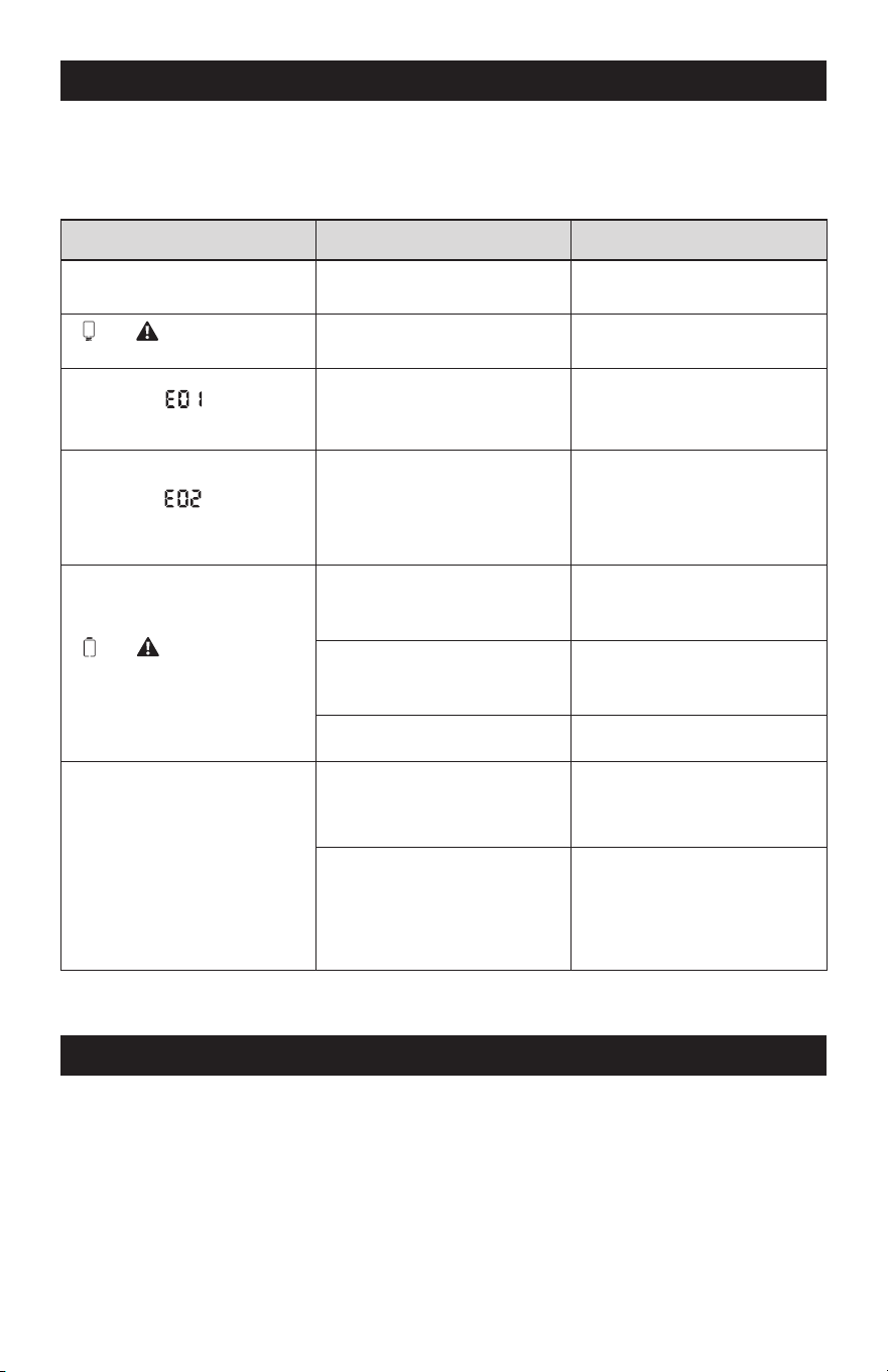
8. TROUBLESHOOTING FAULT CODES
If the charger is not functioning correctly, it may be undergoing an internal electronic
protection a stop normal operation. This is not indicative a defective unit but may require
some troubleshooting to resume normal operation.
Problem Possible Reason Solution
Low or no output voltage
Poor contact with battery or
plug
Reverse polarity
Ensure cables not cracked
and be connected correctly
Disconnect clamps and
ensure proper connection
Allow the charger to cool down,
check for adequate ventilation
Disconnect the clamps, to
check if the battery voltage
is higher than 18V
Disconnect the clamps, select
12V on battery charger, and
then reconnect
Disconnect the clamps, select
6V on battery charger, and
then reconnect
Keep charging until the battery
voltage exceeds 9V. If the
battery voltage cannot reach
9V after 5 minutes, replace
it with a good battery
Replace with a good battery
High temperature
of the internal case
Low or high temperature
outisde the case
and icon flashing
with buzzer alarm
and icon flashing
with buzzer alarm
Fault code icon flashing
with buzzer alarm
Fault code icon flashing
with buzzer intermittent alarm
Ensure that the air temperature
is between -4°F and 104°F for
lead or AGM batteries or
between 14°F and 104°F for
lithium batteries
Battery voltage is too high
Buzzer alarm is sounded
Wrong setting, selected 6V
to charge 12V battery
Wrong setting, selected 12V
to charge 6V battery
The 12V battery is fully
drained or damaged and the
voltage is very low (<9V)
Damaged battery
9. MAINTENANCE AND CARE
9.1 Clean cords and clamps each time you are finished using the charger. Wipe off any battery
fluid or debris that might have come in contact with the clamps to prevent corrosion.
9.2 Store the power and output cable neatly to prevent damage.
9.3 Occasional cleaning of the battery charger case with a soft cloth will help protect the finish.
9.4 Always unplug the charger when not in use.
9.5 Keep the charger stored in a cool, dry place.

Page 11
1. WARRANTY
NOTES

Page 12
NOTES

Page 13
NOTES

Page 14
NOTES

Page 15
6V/12V 15A Battery Charger
WARRANTY
90-DAY MONEY BACK GUARANTEE
This MASTERFORCE™ brand battery charger carries our 90-Day Money Back
Guarantee. If you are not completely satisfied with your MASTERFORCE™
brand product for any reason within ninety (90) days from the date of purchase,
return the item with your original receipt to any MENARDS
®
retail store, and we
will provide you a refund – no questions asked.
3-YEAR LIMITED WARRANTY
This MASTERFORCE™ brand battery charger carries our famous No Hassle
3-Year Limited Warranty to the original purchaser. If, during normal use, this MAS-
TERFORCE™ product breaks or fails due to a defect in material or workmanship
within three (3) years from the date of original purchase, simply bring the item
with the original sales receipt back to your nearest MENARDS
®
retail store. At its
discretion, MASTERFORCE™ agrees to ha
ve the item or any defective part(s)
repaired or replaced with the same or similar MASTERFORCE™ product or part
free of charge, within the stated warranty period, when returned by the original
purchaser with original sales receipt. Not withstanding the foregoing, this limited
warranty does not cover any damage that has resulted from abuse or misuse of
the Merchandise. This warranty: (1) excludes expendable parts including but not
limited to blades, brushes, belts, bits, light bulbs, and/or batteries; (2) shall be
void if this product is used for commercial and/or rental purposes; and (3)
does
not cover any losses, injuries to persons/property or costs. This warranty does
give you specific legal rights and you may have other rights, which vary from
state to state. Be careful, battery chargers are dangerous if improperly used or
maintained. Seller’s employees are not qualified to advise you on the use of this
merchandise. Any oral representation(s) made will not be binding on seller or its
employees. The rights under this limited warranty are to the original purchaser
of the merchandise and may not be transferred to any subsequent owner. This
limited warranty is in
lieu of all warranties, expressed or implied including war-
ranties or merchantability and fitness for a particular purpose. Seller shall not be
liable for any special, incidental, or consequential damages. The sole exclusive
remedy against the seller will be for the replacement of any defects as provided
herein, as long as the seller is willing or able to replace this product or is willing
to refund the purchase price as provided above. For insurance purposes, seller
is not allowed to demonstrate any of these products for you.
For questions/comments, technical assistance or repair parts—
Please call toll free at: 1-877-898-3958.

© 2024 Menard, Inc., Eau Claire, WI 54703
01/2024