Operating and installation
instructions
Induction hobs
To avoid the risk of accidents or damage to the appliance it is essen-
tial to read these instructions before it is installed and used for the
first time.
en-GB M.-Nr. 12 645 301

Contents
2
Warning and Safety instructions ............................................................................... 7
Sustainability and environmental protection.......................................................... 18
Familiarisation................................................................................................................ 19
Hob...................................................................................................................................
19
Controls and display ......................................................................................................
21
Cooking zones.................................................................................................................
23
Power management.......................................................................................................
24
Operating principles.......................................................................................................
25
Networking......................................................................................................................
25
Miele@home............................................................................................................. 25
Functions.........................................................................................................................
26
Con@ctivity............................................................................................................... 26
Permanent pan recognition..................................................................................... 26
Pan and pan size recognition .................................................................................. 26
PowerFlex XL cooking area...................................................................................... 26
Booster....................................................................................................................... 26
Stop&Go.................................................................................................................... 26
Additional power levels............................................................................................ 26
Auto heat-up.............................................................................................................. 26
Timer........................................................................................................................... 26
System lock ............................................................................................................... 27
Safety lock ................................................................................................................. 27
Recall .......................................................................................................................... 27
Keeping warm............................................................................................................ 27
Wipe protection ........................................................................................................ 27
Vapour extraction...................................................................................................... 27
Programming............................................................................................................. 27
Demo mode............................................................................................................... 27
Residual heat indicator ............................................................................................ 27
Safety switch-off....................................................................................................... 28
Overheating protection............................................................................................ 29
Hob data .................................................................................................................... 29
Commissioning.............................................................................................................. 30
Unpacking the hob .........................................................................................................
30
Cleaning the hob for the first time...............................................................................
30
Switching on the hob for the first time........................................................................
30
Using the vapour extraction for the first time ............................................................
30
Miele@home ..................................................................................................................
30
Installing the Miele app ........................................................................................... 30
Setting up Miele@home ......................................................................................... 30

Contents
3
Operation........................................................................................................................ 33
Safety notes for operation.............................................................................................
33
Switching the hob on.....................................................................................................
34
Switching off a cooking zone/the hob.........................................................................
34
Positioning cookware.....................................................................................................
34
Power level ......................................................................................................................
35
Setting the power level............................................................................................ 35
Setting the power level – extended setting range ............................................... 35
Changing the power level ........................................................................................ 35
Manually connecting/disconnecting PowerFlex XL cooking zones........................
35
Booster ............................................................................................................................
36
Activating the Booster ............................................................................................. 36
Deactivating the Booster......................................................................................... 36
Stop&Go .........................................................................................................................
36
Activating Stop&Go ................................................................................................. 36
Deactivating Stop&Go............................................................................................. 36
Auto heat-up ...................................................................................................................
37
Activating auto heat-up............................................................................................ 37
Deactivating auto heat-up....................................................................................... 37
Timer ................................................................................................................................
38
Setting timer durations............................................................................................ 38
Setting the minute minder ...................................................................................... 38
Changing the minute minder duration................................................................... 38
Deleting the minute minder duration..................................................................... 38
Setting the switch-off time ..................................................................................... 39
Changing the switch-off time ................................................................................. 39
Deleting the switch-off time ................................................................................... 39
Setting multiple switch-off times........................................................................... 39
Displaying switch-off times..................................................................................... 39
Using both timer functions at the same time....................................................... 40
System lock.....................................................................................................................
41
Activating the system lock ...................................................................................... 41
Deactivating the system lock.................................................................................. 41
Safety lock.......................................................................................................................
41
Activating the safety lock......................................................................................... 41
Deactivating the safety lock.................................................................................... 41
Activating the Recall function.......................................................................................
42
Activating/deactivating the Keeping warm function .................................................
42
Wipe protection..............................................................................................................
42
Activating wipe protection ...................................................................................... 42
Deactivating wipe protection.................................................................................. 42

Contents
4
Vapour extraction ...........................................................................................................
43
Setting the power level............................................................................................ 43
Switching off the vapour extraction ....................................................................... 43
Activating the Booster ............................................................................................. 43
Deactivating the Booster......................................................................................... 43
Deactivating Con@ctivity temporarily .................................................................. 43
Activating run-on ...................................................................................................... 44
Deactivating run-on.................................................................................................. 44
Hob data ..........................................................................................................................
45
Displaying the model identifier/serial number ..................................................... 45
Displaying the software version ............................................................................. 45
Activating/deactivating demo mode ...........................................................................
45
Setting ranges for the power levels .......................................................................... 46
Good to know................................................................................................................. 47
Hob...................................................................................................................................
47
How induction hobs work........................................................................................ 47
Noises ........................................................................................................................ 47
Pans ............................................................................................................................ 48
Vapour extraction ...........................................................................................................
49
How the vapour extraction works .......................................................................... 49
Operating hours counter.......................................................................................... 50
Air extraction tips...................................................................................................... 50
Adjusting settings ......................................................................................................... 51
Cleaning and care ......................................................................................................... 55
Safety notes on cleaning and care...............................................................................
55
Cleaning the ceramic glass surfaces ...........................................................................
56
Dishwasher-safe components .....................................................................................
56
Cover grille.......................................................................................................................
57
Removing the cover grille ........................................................................................ 57
Cleaning the cover grille by hand ........................................................................... 57
Cleaning the cover grille in the dishwasher .......................................................... 57
Grease filter.....................................................................................................................
57
Removing the grease filter....................................................................................... 57
Cleaning the grease filter by hand.......................................................................... 57
Cleaning the grease filter in the dishwasher......................................................... 58
Fitting the grease filter ............................................................................................. 58
Resetting the grease filter operating hours counter ........................................... 58
Charcoal filter (only KMDA 7876 FL-U)......................................................................
58
Replacing the charcoal filter (only KMDA 7876 FL-U)........................................ 58
Resetting the charcoal filter operating hours counter (only KMDA 7876 FL-
U).................................................................................................................................
59

Contents
5
Cleaning the vapour extraction drip tray.....................................................................
59
Cleaning inside the vapour extraction casing.............................................................
59
Cleaning the inside of the fan unit ...............................................................................
60
Troubleshooting............................................................................................................. 61
Messages in the display................................................................................................
61
Unexpected behaviour...................................................................................................
63
Unsatisfactory results....................................................................................................
64
General problems or technical faults ..........................................................................
64
After sales service......................................................................................................... 66
Contact in the event of a fault......................................................................................
66
Data plate ........................................................................................................................
66
Warranty ..........................................................................................................................
66
Note for test institutes ..................................................................................................
67
Optional accessories.................................................................................................... 68
Installation...................................................................................................................... 69
Safety notes for installation ..........................................................................................
69
Additional safety notes for extraction mode......................................................... 71
Additional safety notes for Plug&Play mode........................................................ 72
Additional safety notes for surface-mounted installation................................... 73
Additional safety notes for flush-fit installation ................................................... 74
Safety distances .............................................................................................................
75
Operating options...........................................................................................................
78
Installation examples.....................................................................................................
79
Building-in dimensions for surface-mounted installation ........................................
81
KMDA 7876 FL-A, KMDA 7876 FL-U.................................................................... 81
Extraction and guided recirculation mode with surface-mounted installation 82
Plug&Play with surface-mounted installation...................................................... 83
Installation dimensions for flush-fit installation.........................................................
84
KMDA 7876 FL-A, KMDA 7876 FL-U.................................................................... 84
Extraction and guided recirculation mode with flush-fit installation................. 85
Plug&Play with flush-fit installation....................................................................... 86
Connection to window contact....................................................................................
87
Installing a surface-mounted hob with extraction and guided recirculation
mode ................................................................................................................................
88
Installing a surface-mounted hob with Plug&Play....................................................
89
Installing a flush-fit hob with extraction and guided recirculation mode...............
90
Installing a flush-fit hob with Plug&Play.....................................................................
91

Contents
6
Rear wall cut-out without drilling template ................................................................
93
Creating the rear wall cut-out with surface-mounted installation and an in-
stallation depth of 23,8cm.....................................................................................
93
Creating the rear wall cut-out with flush-fit installation and an installation
depth of 23,8cm......................................................................................................
94
Creating the rear wall cut-out with surface-mounted installation and an in-
stallation depth of 24,8cm.....................................................................................
95
Creating the rear wall cut-out with flush-fit installation and an installation
depth of 24,8cm ......................................................................................................
96
Electrical connection .....................................................................................................
97
Product data sheets ......................................................................................................
100
UK Conformity declaration ...........................................................................................
102

Warning and Safety instructions
7
This hob complies with all relevant local and national safety re-
quirements. Inappropriate use can, however, lead to personal injury
and material damage.
Read the operating and installation instructions carefully before us-
ing the hob. They contain important information on safety, installa-
tion, use and maintenance. This prevents both personal injury and
damage to the hob.
In accordance with standard IEC60335-1, Miele expressly and
strongly advises that you read and follow the instructions in the
chapter on installing the hob as well as the safety instructions and
warnings.
Miele cannot be held liable for injury or damage caused by non-
compliance with these instructions.
Keep these instructions in a safe place and pass them on to any fu-
ture owner.

Warning and Safety instructions
8
Correct application
This hob is intended for domestic use and use in other similar en-
vironments.
This hob is not intended for outdoor use.
It is intended for domestic use only to cook food and keep it warm.
Any other use is not supported by the manufacturer and could be
dangerous.
This hob is not intended for use by people with reduced physical,
sensory or mental capabilities or lack of experience and knowledge,
unless they have been given supervision and instruction concerning
its use by a person responsible for their safety. They may only use the
hob unsupervised if they have been shown how to use it in a safe
way. They must be able to recognise and understand the dangers of
misuse.

Warning and Safety instructions
9
Safety with children
Children under 8 years of age must be kept away from the hob un-
less they are constantly supervised.
Children over 8years of age may use the hob without supervision
if its operation has been clearly explained to them and they are able
to use it safely. Children must be able to understand and recognise
the possible dangers caused by incorrect operation.
Children must not be allowed to clean the hob unsupervised.
Please supervise children in the vicinity of the hob and do not let
them play with it.
The hob gets hot when in use and remains hot for a while after be-
ing switched off. Keep children well away from the hob until it has
cooled down and there is no danger of burning.
Danger of burning. Do not store anything which might arouse a
child’s interest in storage areas above or behind the hob. Otherwise
they could be tempted to climb onto the hob.
Risk of burning and scalding. Place pots and pans on the cooking
zone in such a way that children cannot pull them down and burn
themselves.
Danger of suffocation! Whilst playing, children may become en-
tangled in packaging material (such as plastic wrapping) or pull it over
their head with the risk of suffocation. Keep packaging material away
from children.
Activate the system lock to ensure that children cannot switch on
the hob inadvertently. Use the safety lock when the hob is in use to
prevent children from altering the settings selected.

Warning and Safety instructions
10
Technical safety
Unauthorised installation, maintenance and repairs can cause con-
siderable danger for the user. Installation, maintenance and repairs
must only be carried out by a Miele authorised technician.
Damage to the hob can compromise your safety. Check the hob for
visible signs of damage. Do not use the hob if it is damaged.
Temporary or permanent operation on an autonomous power sup-
ply system or a power supply system that is not synchronised with
the mains power supply (e.g. island networks, back-up systems) is
possible. A prerequisite for operation is that the power supply system
complies with the specifications of EN50160 or an equivalent stand-
ard.
The function and operation of the protective measures provided in
the domestic electrical installation and in this Miele product must
also be maintained in isolated operation or in operation that is not
synchronised with the mains power supply, or these measures must
be replaced by equivalent measures in the installation. As described,
for example, in the current version of BS OHSAS 18001–2 ISO
45001.
The electrical safety of this hob can only be guaranteed when cor-
rectly earthed. It is essential that this standard safety requirement is
met. If in any doubt please have the electrical installation tested by a
qualified electrician.
To avoid the risk of damage to the hob, make sure that the connec-
tion data on the data plate (voltage and frequency) match the mains
electricity supply before connecting it to the mains.
Consult a qualified electrician if in doubt.
Do not connect the hob to the mains electrical supply by a multi-
socket adapter or extension lead. These are a fire hazard and do not
guarantee the required safety of the appliance.
For safety reasons, this hob may only be used after it has been
built in.
This hob must not be used in a non-stationary location (e.g. on a
ship).
Never open the casing of the hob.
Touching or tampering with electrical connections or components
and mechanical parts is highly dangerous to the user and can cause
operational faults.

Warning and Safety instructions
11
While the hob is under warranty, repairs should only be undertaken
by a Miele authorised service technician. Otherwise the warranty is
invalidated.
Miele can only guarantee the safety of the appliance when genuine
original Miele replacement parts are used. Faulty components must
only be replaced by Miele spare parts.
The hob is not intended for use with an external timer switch or a
remote control system.
The hob must be connected to the electricity supply by a qualified
electrician (see “Installation – Electrical connection”).
If the mains connection cable is damaged, it must be replaced
with a special mains connection cable by a qualified electrician (see
“Installation – Electrical connection”).
The hob must be disconnected from the mains electricity supply
during installation, maintenance and repair work. Ensure that power
is not supplied to the appliance until after it has been installed or until
any maintenance or repair work has been carried out.
Danger of electric shock. Do not use the hob if it is faulty, or if the
ceramic surface is cracked, chipped or damaged in any way. Switch it
off immediately. Disconnect the hob from the mains electricity sup-
ply. Contact Miele Service.
If the hob is installed behind a cabinet door, do not close the door
while the hob is in use. Heat and moisture can build up behind the
closed door. This can result in damage to the hob, the housing unit
and the floor. Do not close the door until the residual heat indicators
go out.
In areas which may be subject to infestation by cockroaches or
other vermin, pay particular attention to keeping the appliance and its
surroundings clean at all times. Any damage caused by cockroaches
or other vermin will not be covered by the warranty.
Warning and Safety instructions
12
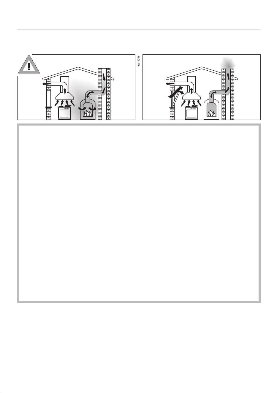
Using at the same time as other heating appliances that depend on the air from
the room
Danger of toxic fumes!
Great care should be taken when using the cooker hood in the
same room or the same area of the house as another heating appli-
ance that depends on the air from the room.
Such heating appliances draw in air from the room and duct ex-
haust gases out through a chimney or extraction ducting. They in-
clude gas, oil, wood and coal-fired boilers and heaters, continuous
flow or other water heaters, gas hobs and ovens.
The cooker hood draws in air from the kitchen and from neighbour-
ing rooms. This applies to the following modes of operation:
- extraction mode,
- recirculation mode with a recirculation box installed outside the
room.
If there is insufficient air, an underpressure will occur. The heating
appliance may be starved of oxygen. This impairs combustion.
Harmful gases could be drawn from the chimney or extraction
ducting back into the room, with potentially fatal consequences.
Risk of death!

Warning and Safety instructions
13
In order to ensure safe operation and to prevent gases given off by
the heating appliance from being drawn back into the room, when
the cooker hood and the heater are both operated simultaneously,
an underpressure in the room of 0.04mbar (4Pa) is the maximum
permissible.
Sufficient ventilation can be maintained by air inlets which cannot
be blocked, e.g. in windows, doors and outside wall vents. The dia-
meter of the inlet openings must enable sufficient ventilation. A
ventilation brick alone is not generally sufficient to ensure safe
ventilation.
The overall ventilation condition of the dwelling must be taken into
account. If in any doubt, the advice of a competent builder, or for
gas, a qualified gas fitter should be sought.
If the cooker hood is being operated in recirculation mode, where
the air is passed back into the room in which the extractor is in-
stalled, the above restrictions do not apply.

Warning and Safety instructions
14
Correct use
The hob gets hot when in use and remains hot for a while after be-
ing switched off. There is a danger of burning until the residual heat
indicators go out.
Oil and fat can overheat and catch fire. Do not leave the hob unat-
tended when cooking with oil and fat. If it does ignite do not attempt
to put the flames out with water.
Disconnect the hob from the mains and use a suitable fire blanket,
saucepan lid, damp towel or similar to smother the flames.
Do not leave the hob unattended whilst it is being used. It should
be continually monitored whilst boiling and flash frying.
Open flames are a fire hazard.
Do not flambé food. When switched on, the cooker hood could draw
flames into the filter. Kitchen grease deposits could ignite.
Spray canisters, aerosols and other inflammable substances can
ignite when heated. Therefore do not store such items or substances
in a drawer under the hob. Cutlery inserts must be heat-resistant.
Do not heat an empty pan.
Do not heat up food in closed containers e.g. tins or sealed jars on
the hob, as pressure can build up in the container, causing it to ex-
plode.
Do not cover the hob, e.g. with a hob cover, a cloth or protective
foil. The material could catch fire, shatter or melt if the hob is
switched on by mistake or if residual heat is still present.
When the appliance is switched on either deliberately or by mis-
take, or when there is residual heat present, there is the risk of any
metal items left on the hob heating up, with the danger of burning.
Depending on the material, other items left on the hob could also
melt or catch fire. Damp pan lids might adhere to the ceramic surface
and be difficult to dislodge. Do not use the appliance as a resting
place. Switch the cooking zones off after use.
You could burn yourself on the hot hob. Protect your hands with
heat-resistant pot holders or gloves when handling hot pots and
pans. Do not let them get wet or damp, as this causes heat to trans-
fer through the material more quickly with the risk of scalding or
burning yourself.

Warning and Safety instructions
15
Hot cooking vapours during cooking can cause the cooker hood to
get hot.
Do not touch the casing or the grease filters until the cooker hood
has cooled down.
When using an electrical appliance, e.g. a hand-held food blender,
near the hob, ensure that the cable of the electrical appliance cannot
come into contact with the hot hob. The insulation on the cable could
become damaged.
Grains of salt, sugar and sand (e.g. from cleaning vegetables) can
cause scratches if they get under pan bases. Make sure that the
ceramic surface is clean before placing pans on it.
Even a light object can cause damage in certain circumstances. Do
not drop anything on the ceramic surface.
Placing hot pans on the sensors and indicators could damage the
electronics underneath. Do not place hot pans on the sensors or in-
dicators.
Do not allow solid or liquid sugar, or pieces of plastic or aluminium
foil to get onto the hob when it is hot, as they can damage the
ceramic surface when it cools down. If this should occur, switch off
the appliance and scrape off all the sugar, plastic or aluminium
residues whilst still hot, using a shielded scraper blade suitable for
use on glass. Wear oven gloves when doing this. Allow the ceramic
surface to cool down and then clean it with a suitable ceramic hob
cleaning agent.
Pans which boil dry can cause damage to the ceramic glass. Do
not leave the hob unattended whilst it is being used.
Only use pots and pans with smooth bases. Rough bases will
scratch the ceramic glass.
Lift pans into position on the hob. Sliding them into place can
cause scuffs and scratches.
Because induction heating works so quickly, the base of the pan
could, under certain circumstances, heat up to the temperature at
which oil or fat self-ignites within a very short time. Never leave the
hob unattended during use!
Heat oil or fat for a maximum of one minute. Never use the
Booster function to heat oil or fat.

Warning and Safety instructions
16
For people fitted with a heart pacemaker: Please note that the area
immediately surrounding the hob is electromagnetically charged. It is
very unlikely to affect a pacemaker. However, if in any doubt, consult
the manufacturer of the pacemaker or your doctor.
To prevent damage to items which are susceptible to electromag-
netic fields, e.g. credit cards, digital storage devices, pocket calculat-
ors, etc, do not leave them in the immediate vicinity of the hob.
Metal utensils stored in a drawer under the hob can become hot if
the appliance is used intensively for a long time.
The hob is fitted with a cooling fan. If a drawer is fitted directly un-
derneath the hob, ensure that there is sufficient space between the
drawer and its contents and the underside of the hob in order to en-
sure sufficient ventilation for the hob.
If a drawer is fitted directly underneath the hob, do not store any
pointed or small items, paper, serviettes, etc. in the drawer. They
could get in through the ventilation slots or be sucked into the casing
by the fan and damage the fan or impair cooling.
Never use two items of cookware on a cooking zone, extended
zone or Flex cooking area at the same time.
If the cookware only partially covers a cooking or extended zone,
the handle could become very hot.
Always place cookware in the middle of a cooking or extended zone!
Only use the Flex cooking area for rectangular or oval oven dishes.
Deposits of grease and dirt will prevent the cooker hood from
working properly.
Do not use the cooker hood without the grease filters in place. Other-
wise cooking vapours will not be cleaned.
There is a risk of fire if cleaning is not carried out as described in
these operating instructions.
Do not cover the vapour extraction cover grille when in use.
Do not place hot cookware on the vapour extraction cover grille.
This will impair the function of the vapour extraction and may damage
the cover grille.
Liquids can damage the cooker hood if they get into it. Keep liquids
away from the cooker hood.
Light objects can be drawn into the cooker hood and impair its op-
eration. Do not place any light objects (e.g. paper towels) within
close proximity of the cooker hood.

Warning and Safety instructions
17
The induction generators could be damaged or even destroyed if
you use an induction adapter plate for cookware. Do not use induc-
tion adapter plates.
Cleaning and care
Do not use a steam cleaning appliance to clean this hob.
The steam could reach electrical components and cause a short cir-
cuit.
If the hob is installed above a pyrolytic oven or cooker, do not use
the hob during a pyrolytic cleaning programme as this could trigger
the overheating protection device on the hob (see “Familiarisation –
Safety switch-off”).
Cosmetic products, especially sunscreen, and hand disinfectants
can leave stains on matt glass surfaces. If cosmetic products come
into contact with a matt glass surface, remove the residue immedi-
ately with hot water, washing-up liquid and a clean microfibre cloth.
Accessories
Only use genuine original Miele accessories and spare parts with
this appliance. Using accessories or spare parts from other manufac-
turers will invalidate the warranty and Miele cannot accept liability.
Miele will guarantee to supply functional spare parts for a min-
imum of 10years and up to 15years following the discontinuation of
your hob.
Sustainability and environmental protection
18
Energy saving tips
- Cook in covered pots and pans if pos-
sible. This prevents heat escaping un-
necessarily.
- Cook with as little water as possible.
- Once food has come to the boil or the
pan is hot for frying, reduce the heat
to a lower power level.
- Use a pressure cooker to reduce
cooking durations.
Disposing of the packaging ma-
terial
The packaging material is used for hand-
ling and protects the appliance from
transport damage. The packaging ma-
terial used is selected from materials
which are environmentally friendly for
disposal and can generally be recycled.
Recycling the packaging material re-
duces the use of raw materials. Use ma-
terial-specific collection points for valu-
able materials and take advantage of re-
turn options. Your Miele dealer will take
the packaging material away.
Disposing of your old appliance
Electrical and electronic appliances con-
tain many valuable materials. They also
contain certain materials, compounds
and components which were essential
for their correct functioning and safety.
These could be hazardous to human
health and to the environment if dis-
posed of with household waste or if
handled incorrectly. Please do not,
therefore, dispose of your old appliance
with household waste.
Instead, please make use of officially
designated collection and disposal
points to dispose of and recycle elec-
trical and electronic appliances in your
local community, with your dealer or
with Miele, free of charge. By law, you
are solely responsible for deleting any
personal data from the old appliance
prior to disposal. You are legally obliged
to remove any old batteries which are
not securely enclosed by the appliance
and to remove any lamps without des-
troying them, where this is possible.
These must be taken to a suitable col-
lection point where they can be handed
in free of charge. Please ensure that
your old appliance poses no risk to chil-
dren while being stored for disposal.
Familiarisation
19
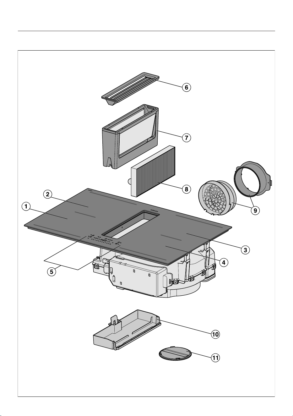
Hob

Familiarisation
20
a
PowerFlex XL cooking zone with TwinBooster
b
PowerFlex XL cooking zone with TwinBooster
can be combined with PowerFlexXL cooking zone to form PowerFlexXL
cooking area
c
PowerFlex XL cooking zone with TwinBooster
can be combined with PowerFlexXL cooking zone to form PowerFlexXL
cooking area
d
PowerFlex XL cooking zone with TwinBooster
e
Controls and indicators
f
Cover grille
g
Grease filter
h
Charcoal filter
KMDA 7876 FL-U only
i
Plug&Play adapter
KMDA 7876 FL-U only
j
Removable drip tray
k
Cleaning flap
Familiarisation
21
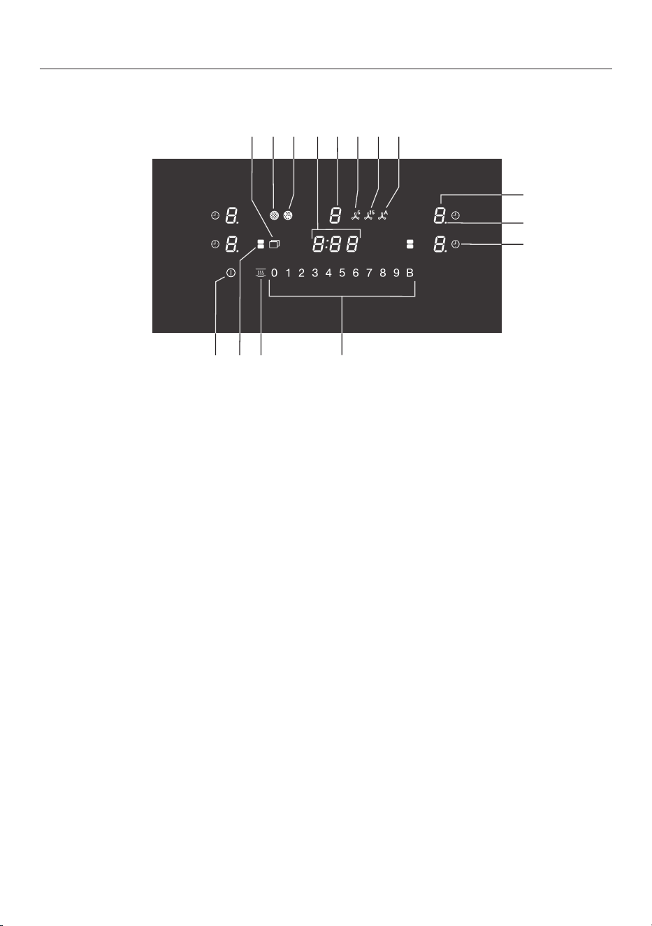
Controls and display
f
d
c
a
b
m
no
l
jk i h
g
e
a
Hob On/Offsensor control
b
PowerFlex XL cooking zones sensor control
For manual connection/disconnection of PowerFlexXL cooking zones
c
Keeping warm sensor control
To activate/deactivate the Keeping warm function
d
Numerical display sensor controls
– To set the power level
– To set the times
e
Auto switch off sensor control
Switches the cooking zones off automatically
f
Power level display – extended setting range
g
Cooking zone selection and display sensor control
Cooking zone is ready for operation
to Power level
Residual heat
Auto heat-up
Cookware missing or unsuitable
TwinBooster level 1
TwinBooster level 2
Keeping warm

Familiarisation
22
h
Con@ctivity sensor control
For activating/deactivating the Con@ctivity function of the built-in vapour ex-
traction
i
Sensor control for the 15minute run-on option
j
Sensor control for the 5minute run-on option
k
Vapour extraction selection and display sensor control
Vapour extraction is ready for operation
to Power level
(can be changed to 3 levels)
Booster function is activated
l
Timer display
: to
:
Time
System lock/safety lock is activated
Demo mode is activated
m
Charcoal filter indicator
The charcoal filter must be cleaned
n
Grease filter indicator
Grease filter must be cleaned
o
Menu sensor control for displaying the following sensor controls
Wipe protection sensor control
For locking the sensor controls
Minute minder sensor control
+ Entry sensor control
– For changing the programming
– For amending the times
Stop&Go sensor control
For stopping/starting a cooking process in progress
Familiarisation
23
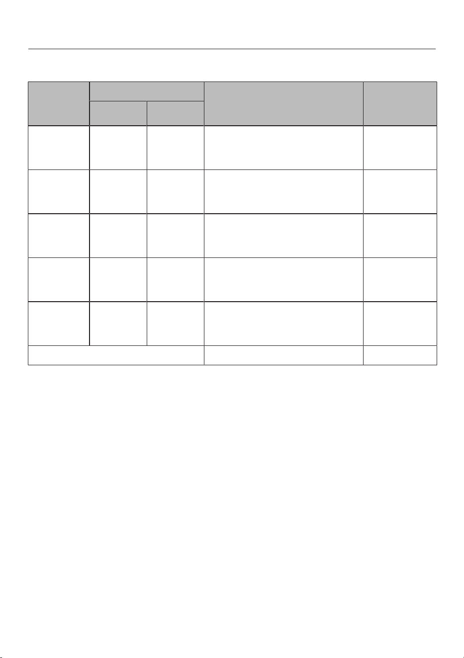
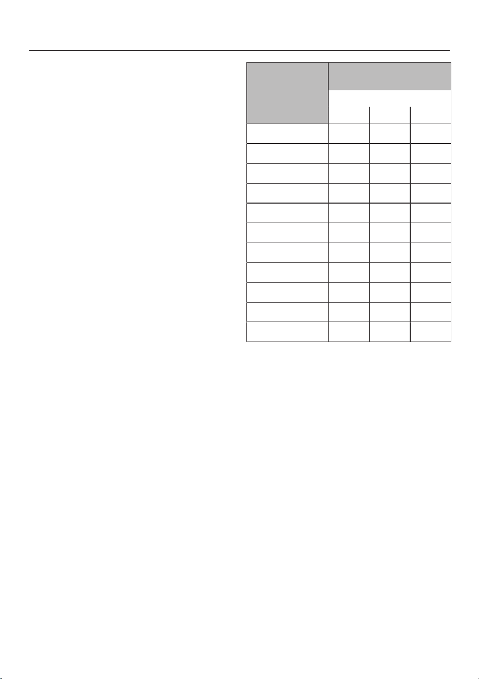
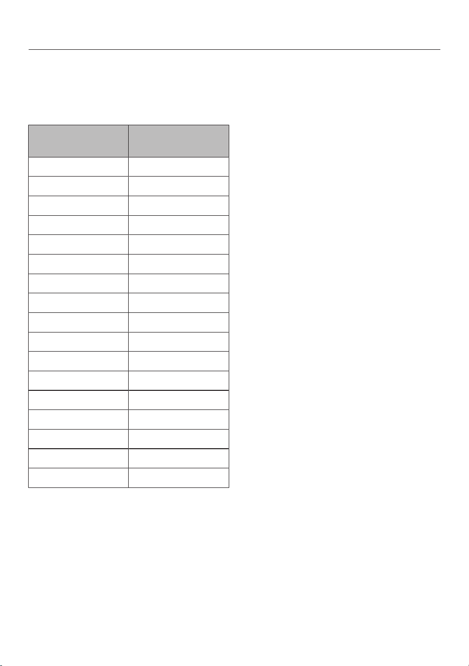
Cooking zones
Cooking
zone
Size in cm
1
Max. rating in watts for
230V
2
Linked
cooking
zone
3
Ø
15–23
15x15
–
23x23
Normal
TwinBooster, level 1
TwinBooster, level 2
2100
3000
3650
15–23
15x15
–
23x23
Normal
TwinBooster, level 1
TwinBooster, level 2
2100
3000
3650
15–23
15x15
–
23x23
Normal
TwinBooster, level 1
TwinBooster, level 2
2100
3000
3650
15–23
15x15
–
23x23
Normal
TwinBooster, level 1
TwinBooster, level 2
2100
3000
3650
+
+
–
15x25
–
23x46
Normal
TwinBooster, level 1
TwinBooster, level 2
3400
4800
7300
-
Total 7300
1
Cookware with a base diameter/surface (widthxdepth) within the given range may be used.
2
The power given may vary depending on the size and material of the cookware used.
3
The cooking zone is linked to this cooking zone electrically so that the rating can be increased (see
“Familiarisation – Power management”).

Familiarisation
24
Power management
Total power
The hob has a maximum total permitted
power consumption which cannot be
exceeded for safety reasons. You can re-
duce the maximum total permitted
power consumption (see “Adjusting set-
tings”).
The higher the total permitted power
consumption of the hob, the more
power levels/functions can be used on
all cooking zones at the same time.
If the set power levels/functions require
more power than can be provided in ac-
cordance with the total permitted power
consumption, the hob will distribute the
maximum permitted power between the
cooking zones.
Distribution of power
Cooking zones can be linked together in
pairs on the hob. This allows power to
be transferred from one cooking zone
(A) to another (B). As a result, the power
of cooking zone (A) is reduced.
Example: the Booster function for cook-
ing zone (B) is activated.
Cooking zone (B) which requires addi-
tional power is determined by the most
recent setting on the hob.
The values for the maximum total per-
mitted power consumption and which
cooking zones are linked together can
be found in “Familiarisation – Cooking
zone data”.
You can reduce the maximum total
permitted power consumption (see
“Adjusting settings”).
Effects of power distribution
If a cooking zone gives power to another
zone, this can have the following effects
on the zone giving the power:
- The power level is reduced.
- Auto heat-up is deactivated. Cooking
continues at the set level. If the power
is not sufficient, the power level will
be reduced again.
- The Booster function is deactivated.
- The cooking zone is switched off.
When the cooking zone stops transfer-
ring power to the other zone, the power
level can be increased again.
Tip: If you wish to cook a large quantity
of food on one cooking zone, switch the
other cooking zones to lower power
levels.
Familiarisation
25
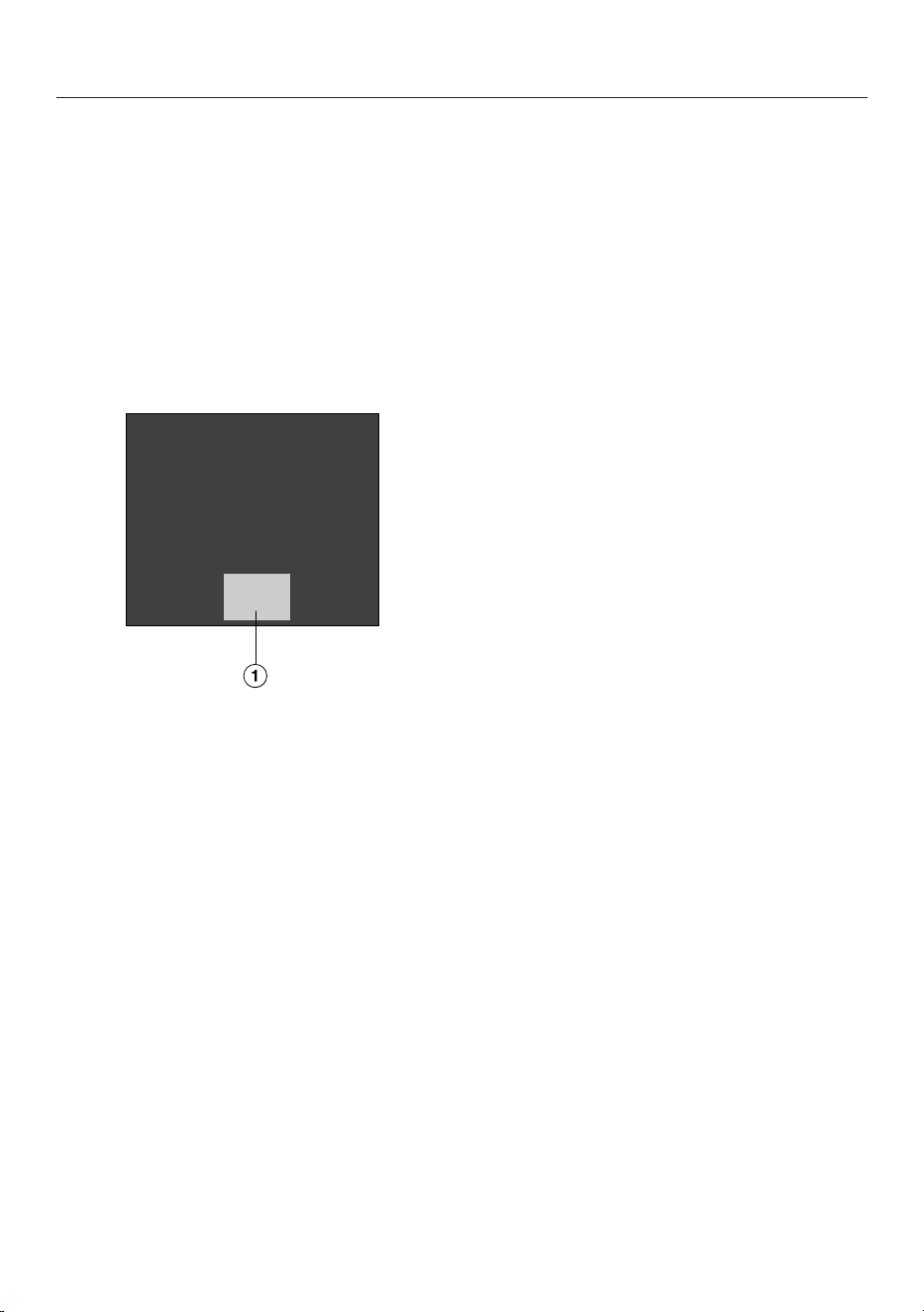
Operating principles
Hob when switched off
Only the printed symbol for the On/
Offsensor control is visible when the
hob is switched off. More sensor con-
trols light up when the hob is switched
on.
Operation
a
Sensor controls and indicators
This ceramic glass hob is equipped with
sensor controls which react to finger
contact.
Each time a sensor control is activated,
an audible signal sounds.
For safety reasons, in order to switch
the appliance on, the On/Offsensor
control needs to be touched for a little
longer than the other sensors.
Selecting a cooking zone
If you want to configure settings for a
cooking zone, the cooking zone must be
selected first.
To select a cooking zone, touch the rel-
evant cooking zone indicator. The relev-
ant cooking zone indicator will appear
brighter when touched.
When the cooking zone indicator ap-
pears brighter, the cooking zone is se-
lected and you can configure settings
for the cooking zone.
Exception: if only one of the cooking
zones is in operation, you can configure
settings without selecting the cooking
zone.
Networking
Your hob is equipped with an integrated
WiFi module. The hob can be connected
to your home WiFi network or simply to
your Miele cooker hood.
Miele@home
After installing the Miele app on a mo-
bile device, you can do the following:
- Call up information on the operating
status of your hob
- Call up information on the programme
sequence of your hob
- Set up a Miele@home network with
other WiFi-enabled Miele domestic
appliances

Familiarisation
26
Functions
Con@ctivity
The vapour extraction will switch itself
on automatically if there is an item of
cookware on the cooking zone and a
power level has been set for that zone.
The power level for vapour extraction is
set to suit the power level of the cook-
ing zone. The run-on time and level de-
pend on the power level of the vapour
extraction.
You can deactivate Con@ctivity tem-
porarily or permanently.
Permanent pan recognition
When you place cookware on a cooking
zone, the numerical display for the
cooking zone is activated automatically.
Pan and pan size recognition
The cookware and its size are detected
within a cooking zone. The release of
energy is adapted to the size of the pan.
PowerFlex XL cooking area
A PowerFlex XL cooking area joins to-
gether 2 PowerFlex XL cooking zones,
making it possible to use larger cook-
ware.
The PowerFlex XL cooking zones com-
bine automatically to form a PowerFlex
XL cooking area when you place suffi-
ciently large items of cookware on them
(see “Familiarisation – Cooking zone
data”). The PowerFlex XL cooking zones
can also be combined manually.
Booster
When the Booster function is activated,
the power is boosted so that large
quantities can be heated up quickly, e.g.
when boiling water for cooking pasta.
Stop&Go
When Stop&Go is activated, all power
levels are reduced to1.
When the function is deactivated, the
appliance switches back to the power
level that was set last.
Tip: Use this function if there is a
danger of food boiling over.
Additional power levels
You can activate additional levels
between the existing power levels.
These intermediate levels allow you to
adjust the power more precisely for the
cookware.
Auto heat-up
When auto heat-up has been activated,
the cooking zone switches on automat-
ically at the highest setting and then
switches to the power level (continued
cooking setting) which you have previ-
ously selected.
Timer
The timer can be used for the following
two functions:
- For setting the minute minder
- For automatically switching a cooking
zone off
You can use the functions simultan-
eously.
Minute minder
You can set an alarm for activities that
are independent of the hob.
Auto switch off
You can set a time after which a cooking
zone will switch off automatically. This
function can be used for all cooking
zones at the same time.

Familiarisation
27
System lock
If the system lock is activated, then the
hob cannot be switched on.
Safety lock
The safety lock is activated when the
hob is switched on. When the lock is ac-
tivated, the hob can be operated only
under certain conditions.
Recall
If the hob is switched off by mistake
during use, this function can be used to
reset all settings. For this to work, the
hob must be switched on again within
10seconds of being switched off.
Keeping warm
This function enables food to be kept
warm after it has finished cooking.
The maximum duration for keeping food
warm is 2hours.
Wipe protection
The hob sensor controls can be locked
for 20s to remove soiling, for example.
The sensor control is not locked.
Vapour extraction
Air close to the cookware is drawn in
and cleaned by a grease filter. Depend-
ing on the type of operation, the air is
then conveyed out of the building or
cleaned further by a charcoal filter and
conveyed back into the room.
Programming
You can adapt the programming of the
hob to your personal needs.
Demo mode
This function enables dealers to demon-
strate the hob without it heating up.
Residual heat indicator
If the cooking zone is still hot, the resid-
ual heat indicator will light up after it has
been switched off.
The bars of the residual heat indicator
go out one after the other as the cook-
ing zone cools down. The last bar only
goes out when the cooking zone is safe
to touch.
Familiarisation
28
Safety switch-off
Sensor controls are covered
Your hob will turn off automatically if
one or several of the sensor controls re-
main covered for longer than
10seconds; for example, by finger con-
tact, food boiling over or by an object
such as an oven glove or tea towel. will
flash briefly in the timer display and a
tone will sound.
will go out once you have removed the
object and/or cleaned the hob and the
hob will be ready to use again.
Excessive operating time
The safety switch-off mechanism is
triggered automatically if a cooking zone
is heated for an unusually long period of
time. This time depends on the power
level selected. If it has been exceeded,
the cooking zone switches off and the
residual heat indicator appears. If you
switch the cooking zone off and on
again, it is ready for operation again.
You can adjust the safety switch-off by
changing the safety setting (see “Ad-
justing settings”).
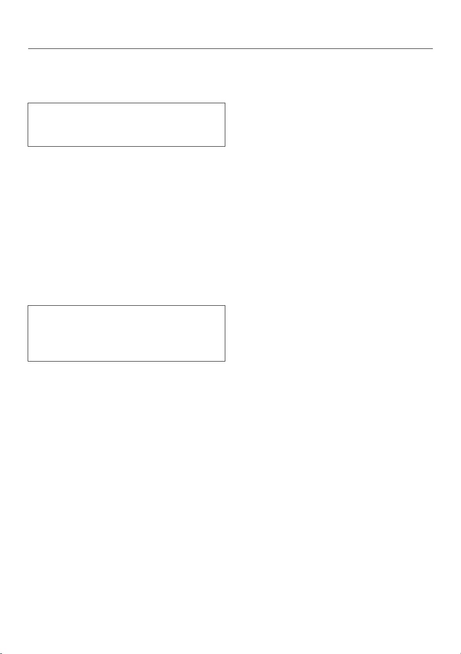
Power level* Maximum operating time
[h:min]
Safety setting
0** 1 2
1 10:00 8:00 5:00
1. 10:00 7:00 4:00
2/2. 5:00 4:00 3:00
3/3. 5:00 3:30 2:00
4/4. 4:00 2:00 1:30
5/5. 4:00 1:30 1:00
6/6. 4:00 1:00 0:30
7/7. 4:00 0:42 0:24
8 4:00 0:30 0:20
8. 4:00 0:30 0:18
9 1:00 0:24 0:10
* The power levels with a dot after the num-
ber are only available if the power level range
has been extended (see “Setting ranges”).
** Factory default setting

Familiarisation
29
Overheating protection
In order to prevent the hob from being
damaged by excessive temperatures,
the overheating protection mechanism
intervenes in one of the following ways:
Overheating protection measures
- If the Booster function is switched on,
it will stop.
- The set power level will be reduced.
- A cooking zone will switch off. will
flash alternately with in the timer
display.
- All cooking zones will switch off.
Triggering the overheating protection
mechanism
The overheating protection may be ac-
tivated under the following circum-
stances:
- The cookware being heated is empty.
- Fat or oil is being heated on a high
power level.
- Insufficient ventilation to the under-
side of the hob.
- A hot cooking zone is switched back
on after an interruption to the power
supply.
Hob data
The model identifier, serial number and
software version of the hob can be dis-
played.

Commissioning
30
Unpacking the hob
Please stick the data plate for the ap-
pliance, supplied with this document-
ation, in the space provided in the
“Customer Service Department” sec-
tion of this booklet.
Remove any protective foil and stick-
ers.
Cleaning the hob for the first
time
Before using for the first time, clean
the hob with a damp cloth.
Wipe the hob dry.
Switching on the hob for the
first time
The metal components have a protect-
ive coating. When the hob is used for
the first time, this causes a smell and
possibly also vapour. The heating of the
induction coils also causes odours in
the first few hours of operation. With
each subsequent use, the odour is re-
duced until it disappears completely.
The smell and any vapours given off do
not indicate a faulty connection or appli-
ance and they are not hazardous to
health.
Using the vapour extraction for
the first time
Only: KMDA 7876 FL-U
Insert the charcoal filter (see “Clean-
ing and care – Replacing the charcoal
filter”).
Miele@home
Installing the Miele app
The ability to use the Miele app de-
pends on the availability of the
Miele@home service in your country.
For information about availability, please
visit www.miele.com.
The Miele app is available free of charge
from the Apple App Store
®
or from the
Google Play Store™.
Install the Miele app on your mobile
device.
Setting up Miele@home
The WiFi connection shares a frequency
range with other appliances (including
microwave ovens and remote control
toys). This can give rise to sporadic or
even complete connection failures.
Therefore, the availability of featured
functions cannot be guaranteed.
The hob requires max. 2W in networked
standby.
There are a number of ways of connect-
ing your hob to your WiFi network.

Commissioning
31
Connecting via the Miele app
- A home WiFi network is available.
- The signal of your WiFi network is
sufficiently strong in the place
where your hob is installed.
- There is no direct WiFi connection
between the hob and a Miele
cooker hood (Con@ctivity).
- The Miele app is installed on your
mobile device.
Start the Miele app.
Switch the hob on.
Touch any cooking zone indicator.
Touch the 0 and 5sensor controls at
the same time for 6seconds.
The seconds can be seen counting
down in the timer display. After this time
has elapsed, the code: is displayed
in the timer display for 10seconds.
You now have 10minutes to configure
the WiFi.
Follow the user navigation in the app.
You can use all Miele@home functions.
Connecting via WPS
- A home WiFi network is available.
- The signal of your WiFi network is
sufficiently strong in the place
where your hob is installed.
- There is no direct WiFi connection
between the hob and a Miele
cooker hood (Con@ctivity).
- You must have a WPS (WiFi pro-
tected setup) compatible router.
Touch any cooking zone indicator.
Touch the 0 and 6sensor controls at
the same time for 6seconds.
The seconds can be seen counting
down in the timer display. After the time
has elapsed, a progress light appears in
the timer display during the connection
attempt (for max. 120seconds).
The WPS login is active during these
120seconds.
Activate the WPS function on your
WiFi router.
If the connection was successful, the
code: appears in the timer display.
If the connection could not be estab-
lished, the timer display will show the
code:. You have probably not activ-
ated WPS on your router quickly
enough. Repeat the steps above.
Install the Miele app.
Follow the user navigation in the app.
You can use all Miele@home functions.
Tip: If your WiFi router does not support
WPS, please connect via the Miele app.

Commissioning
32
Cancelling the process
Touch any sensor control.
Resetting settings
Reset the settings if you are disposing
of your hob, selling it or putting a used
hob into operation. This is the only way
to ensure that all personal data has
been removed and the previous owner
will no longer be able to access the hob.
Resetting is not required when replacing
the router.
Switch the hob on.
Touch any cooking zone indicator.
Touch the 0 and 9sensor controls at
the same time for 6seconds.
The seconds can be seen counting
down in the timer display.
After this time has elapsed, the
code: is displayed in the timer dis-
play for 10seconds.
Operation
33
Safety notes for operation
Risk of fire with overheated food.
Unattended food can overheat and catch alight.
Do not leave the hob unattended whilst it is being used.
Risk of burning due to hot cooking zones.
The cooking zones will be hot after use.
Do not touch the cooking zones while the residual heat indicators
are on.
Risk of burning due to hot items.
When the hob is switched on either deliberately or by mistake, or
when there is residual heat present, there is the risk of metal items
placed on the hob heating up.
Do not use the hob as a resting place for anything.
After use, switch the hob off with the sensor control.
Placing hot cookware on the sensor controls and displays can
damage the electronic module underneath.
The sensor controls do not respond.
They may be switched on or off unintentionally.
The hob will switch itself off (see “Familiarisation – Safety switch-
off”).
Do not place hot cookware over the sensor controls or displays.
Operation
34
Switching the hob on
Touch the sensor control.
Further sensor controls will light up.
If no further entry is made, the hob will
switch itself off after a few seconds for
safety reasons.
Switching off a cooking zone/
the hob
Switching the hob off
To switch off the hob and all the cook-
ing zones, touch the sensor con-
trol.
Switching off a cooking zone
Touch and hold the relevant cooking
zone indicator until the cooking zone
switches off.
or
Touch the relevant cooking zone in-
dicator.
The cooking zone indicator appears
brighter.
Touch the 0sensor control on the nu-
merical display.
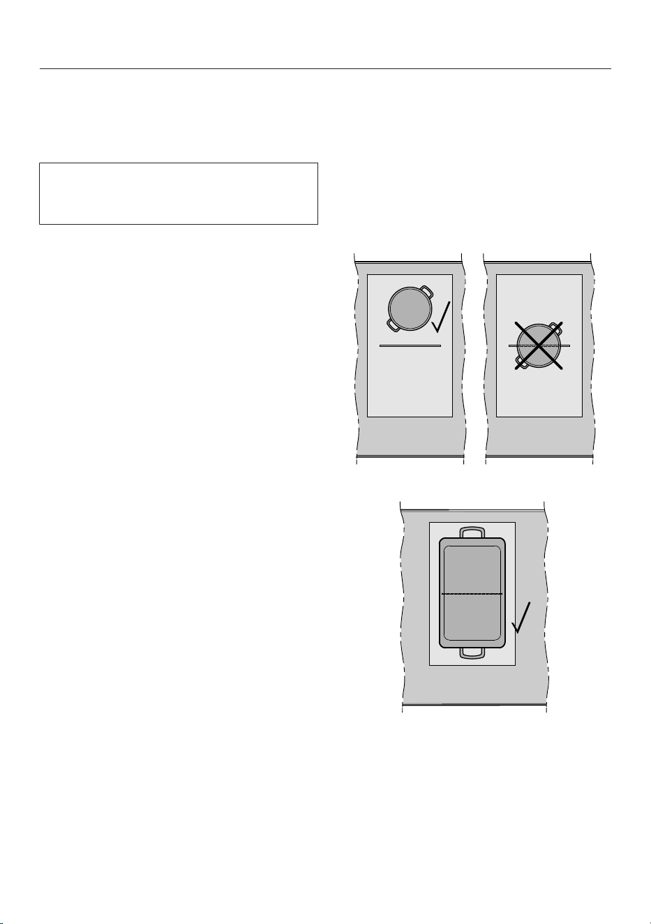
Positioning cookware
Refer to the cooking zone data for your
hob model for information about cook-
ware sizes and the corresponding posi-
tions (see “Familiarisation – Cooking
zone data”).
Position the cookware as shown be-
low:
PowerFlex XL cooking zone
PowerFlex XL cooking area

Operation
35
Power level
Setting the power level
Permanent pan recognition is activated
as standard (see “Adjusting settings”).
When the hob is switched on and you
place an item of cookware on a cooking
zone, the cooking zone indicator starts
to flash.
Place the cookware on the cooking
zone you want to use.
Touch the appropriate sensor control
for the power level you want on the
numerical display.
Setting the power level – extended
setting range
Press the numerical display between
the sensor controls.
A dot appears after the power level in
the cooking zone selection.
The sensor controls to the left of the in-
terim level light up brighter than the
other sensor controls.
Example:
If you have set power level 7., the cook-
ing zone selection will show 7..
The number 7 on the numerical display
will light up brighter than the other
sensor controls.
Changing the power level
Touch the relevant cooking zone in-
dicator.
The cooking zone indicator appears
brighter.
Touch the appropriate sensor control
for the power level you want on the
numerical display.
Manually connecting/discon-
necting PowerFlex XL cooking
zones
To manually connect or disconnect
the PowerFlex XL cooking zones,
touch the sensor control.

Operation
36
Booster
Activating the Booster
When the Booster function is activated,
the settings for the linked cooking zone
may be changed (see “Familiarisation –
Power management”).
You can use the Booster:
- On any cooking zone on either side
or
- On both cooking zones on one side
or
- On a PowerFlex XL cooking area
The Booster function is active for a max-
imum of 15minutes.
TwinBooster level 1
Place the cookware on the cooking
zone you want to use.
Select a power level if necessary.
Touch the Bsensor control.
will appear in the cooking zone indic-
ator.
TwinBooster level 2
Place the cookware on the cooking
zone you want to use.
Select a power level if necessary.
Touch the Bsensor control twice.
will appear in the cooking zone indic-
ator.
Deactivating the Booster
Touch the Bsensor control.
or
Set another power level.
If you deactivate the Booster function or
the Booster time comes to an end and
- no power level was selected before
activating the Booster, the cooking
zone will revert automatically to
level9.
- a power level was selected before ac-
tivating the Booster, the cooking zone
will revert automatically to the previ-
ously selected level.
Stop&Go
Activating Stop&Go
The cooking zone power levels and the
timer settings cannot be altered; the
hob can only be switched off. The
minute minder, switch-off, Booster and
heat-up times continue to run.
If the function is not deactivated within
1hour, the hob will switch off.
Touch the sensor control.
Touch the sensor control.
Deactivating Stop&Go
Touch the sensor control.
Operation
37
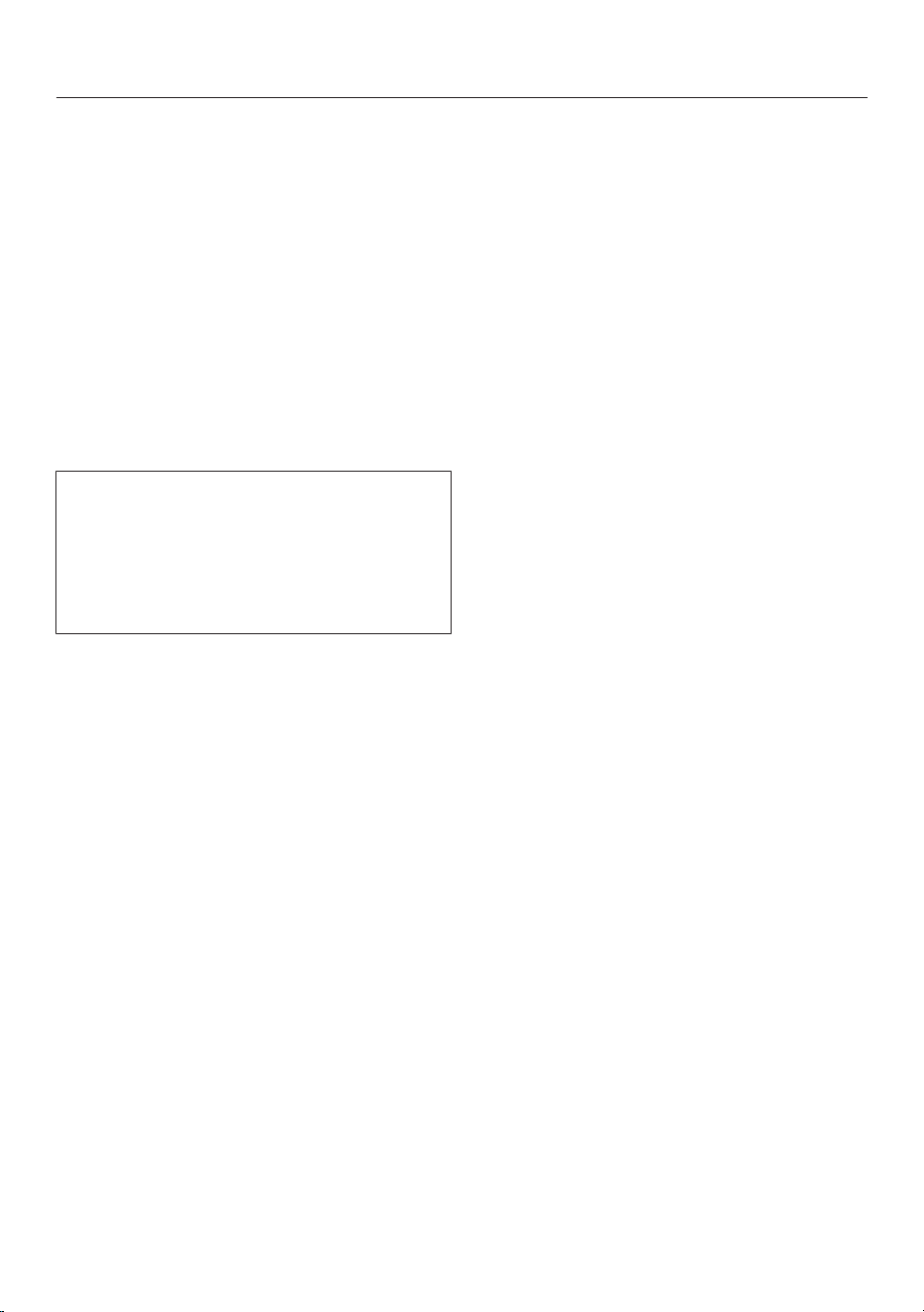
Auto heat-up
The heat-up time depends on which
continued cooking setting has been
chosen:
Continued cook-
ing setting*
Heat-up time
[min:sec]
1 Approx. 0:15
1. Approx. 0:15
2 Approx. 0:15
2. Approx. 0:15
3 Approx. 0:25
3. Approx. 0:25
4 Approx. 0:50
4. Approx. 0:50
5 Approx. 2:00
5. Approx. 5:50
6 Approx. 5:50
6. Approx. 2:50
7 Approx. 2:50
7. Approx. 2:50
8 Approx. 2:50
8. Approx. 2:50
9 –
* The continued cooking settings with a dot
after the number are only available if the
power level range has been extended (see
“Adjusting settings”).
Activating auto heat-up
Briefly touch the indicator for the re-
quired cooking zone.
Touch the sensor control for the con-
tinued cooking setting you want until
a tone sounds and lights up in the
cooking zone indicator.
The symbol flashes alternately with
the power level selected in the cooking
zone indicator during the heat-up time
(see chart).
Deactivating auto heat-up
Briefly touch the indicator for the re-
quired cooking zone.
Touch the continued cooking setting
you have set until the switches off.
or
Set another power level.

Operation
38
Timer
Setting timer durations
A duration of between 1minute (:)
and 9hours 59minutes (:) can be
set.
Durations of up to 59minutes are
shown in minutes (00:59) and durations
of more than 60minutes are shown in
hours and minutes.
Durations are entered using the numer-
ical display and can be adjusted with
the +sensor control.
Enter durations in the order of hours,
followed by minutes in tens and then
units.
Example:
59minutes = 00:59hours,
Enter: 5-9
80minutes = 1:20hours,
Enter: 1-2-0
After the first number has been entered,
the timer display will light up constantly.
After the second number has been
entered, the first number will move to
the left. After the third number has been
entered, the first and second numbers
will move to the left.
Setting the minute minder
Touch the sensor control.
Touch the sensor control.
The timer display flashes.
Set the required duration (see “Timer
– Setting timer durations”).
Touch the sensor control or wait
10seconds to start the minute minder.
Changing the minute minder duration
Touch the sensor control.
The timer display flashes.
Set the required duration (see “Timer
– Setting timer durations”).
Touch the sensor control or wait
10seconds to start the minute minder.
Deleting the minute minder duration
Touch the sensor control.
Touch on the numerical display.

Operation
39
Setting the switch-off time
A cooking zone will switch off when the
maximum operating time has elapsed,
independently of a set switch-off time
(see “Familiarisation – Safety switch-
off”).
A power level is set for the desired
cooking zone.
Touch the sensor control next to
the relevant cooking zone indicator.
The timer display flashes.
Set the required duration (see “Timer
– Setting timer durations”).
Touch the sensor control or wait
10seconds to start the switch-off time.
The switch-off time for the cooking zone
will count down and the sensor con-
trol will light up constantly.
Changing the switch-off time
Touch the required cooking zone in-
dicator.
Touch the sensor control next to
the relevant cooking zone indicator.
The timer display flashes.
Set the required duration (see “Timer
– Setting timer durations”).
Touch the sensor control or wait
10seconds to start the switch-off time.
The switch-off time for the cooking zone
will count down and the sensor con-
trol will light up constantly.
Deleting the switch-off time
Touch the required cooking zone in-
dicator.
Touch the sensor control of the re-
quired cooking zone until the
:symbol appears in the timer dis-
play.
or
Touch the sensor control next to
the relevant cooking zone indicator.
The timer display flashes.
Touch the sensor control on the nu-
merical display.
Setting multiple switch-off times
To set a switch-off time for another
cooking zone, follow the steps de-
scribed in “Operation – Setting the
switch-off time”.
If multiple switch-off times are pro-
grammed, the timer display for the most
recently selected cooking zone is dis-
played. The sensor control next to
the relevant cooking zone indicator
lights up brighter.
Displaying switch-off times
If you want to show the time left for
another cooking zone which is count-
ing down in the background, touch
the sensor control for the desired
cooking zone.
The rounded up time left is displayed
for the required cooking zone.

Operation
40
Using both timer functions at the
same time
If you use both functions at the same
time, the time of the last selected func-
tion is always displayed.
Touch the sensor control or the rel-
evant cooking zone indicator if you
want to show the times left counting
down in the background.
Operation
41
System lock
Activating the system lock
All sensor controls are locked. A set
minute minder time will continue to
count down.
Touch the sensor control for
6seconds.
The seconds can be seen counting
down in the timer display. When this
time has elapsed, will appear in the
timer display. The system lock is activ-
ated.
If a disallowed sensor control is touched
whilst the system lock is activated,
will appear in the timer display for a few
seconds and a buzzer will sound.
The system lock can be programmed
to be activated automatically
5minutes after the hob has been
switched off (see “Adjusting settings”).
Deactivating the system lock
Touch the sensor control for
6seconds.
will appear briefly in the timer dis-
play and then the seconds will count
down. The system lock is deactivated
once the time has elapsed.
Safety lock
Activating the safety lock
When the safety lock is activated:
- The cooking zones, the hob and the
vapour extraction can only be
switched off
- A set minute minder time can be
modified
- The sensor control can be activ-
ated
Touch the sensor control.
Touch and hold the and sensor
controls at the same time for
6seconds.
The seconds can be seen counting
down in the timer display. When this
time has elapsed, will appear in the
timer display. The safety lock is activ-
ated.
If a disallowed sensor control is touched
while the safety lock is activated,
will appear in the timer display for a
few seconds and a buzzer will sound.
Deactivating the safety lock
Touch and hold the and sensor
controls at the same time for
6seconds.
will appear briefly in the timer dis-
play and then the seconds will count
down. Once the time has elapsed, the
safety lock function is deactivated.

Operation
42
Activating the Recall function
Switch the hob on again.
Immediately after switching the hob
on, touch one of the flashing cooking
zone indicators.
Activating/deactivating the
Keeping warm function
The Keeping warm function cannot be
used to reheat food that has gone cold.
Touch the cooking zone indicator for
the required cooking zone.
The cooking zone indicator appears
brighter.
Touch the sensor control.
Tips for keeping food warm
- Only use cookware (pots/pans) for
keeping food warm. Cover the cook-
ware with a lid.
- Stir firm or viscous food (mashed
potatoes, stew) occasionally.
- Nutrients are lost when food is
cooked, and continue to diminish
when food is kept warm. The longer
food is kept warm, the greater the
loss of nutrients. Try to ensure that
food is kept warm for as short a time
as possible.
Wipe protection
Activating wipe protection
Touch the sensor control.
Touch the sensor control.
The time counts down in the timer dis-
play.
Deactivating wipe protection
Touch and hold the sensor control
until the timer display goes out.
Operation
43
Vapour extraction
Setting the power level
Power levels 1 to 3 and a Booster level
are set as standard. The power levels
can be extended to 1 to 9 and a Booster
level (see “Adjusting settings”).
If the vapour extraction is not switched
off manually, it will switch itself off auto-
matically 12hours after last being used.
If the cooker hood starts at power
level1, the power is automatically in-
creased to level2 for 20seconds.
The increase in power is necessary in
order to ensure that the flap opens in
extraction mode. If you are using the
cooker hood in recirculation mode, you
can deactivate this automatic function
(see “Adjusting settings”).
Touch the vapour extraction display.
Touch the appropriate sensor control
for the power level you want.
Switching off the vapour extraction
Touch the vapour extraction display.
Touch the 0sensor control.
Activating the Booster
The Booster function is active for a max-
imum of 10minutes.
Touch the vapour extraction display.
Touch the Bsensor control.
Deactivating the Booster
Touch the vapour extraction display.
Set another power level.
Deactivating Con@ctivity temporarily
If you want to deactivate Con@ctivity
permanently, you will need to change
the Con@ctivity programming (see “Ad-
justing settings”). If Con@ctivity is per-
manently deactivated, the sensor
control will no longer be visible.
You can deactivate Con@ctivity in
various ways:
- Touch the sensor control
- Touch the 0sensor control
- Select a different power level
Set the power level you want.
Depending on the programming,
Con@ctivity will be reactivated when
you switch the hob off and back on
again (see “Adjusting settings”).

Operation
44
Activating run-on
The run-on helps to remove any linger-
ing vapours and odours from the air in
the kitchen. There are two run-on times
available:
- (5minutes)
- (15minutes)
The run-on duration will be carried out
using the power level set during activa-
tion. You can change the power level
during the run-on period.
Touch the or sensor control to
activate the run-on period.
Deactivating run-on
If you switch the hob off with the
sensor control, the run-on period will
continue through to the end.
Touch the , or 0sensor control
to deactivate the run-on period.
Operation
45
Hob data
Displaying the model identifier/serial
number
There is cookware on the hob.
Switch the hob on.
Press the 0 and 4sensor controls on
the numerical display at the same
time for 6seconds.
Numbers will appear in the timer display
one after another, separated by a dash.
Example: (model identifier
KMDA1234)– (serial
number)
Displaying the software version
There is cookware on the hob.
Switch the hob on.
Press the 0 and 3sensor controls on
the numerical display at the same
time for 6seconds.
3numbers appear in the timer display:
Example: = software version 1.23.
Activating/deactivating demo
mode
There is cookware on the hob.
Switch the hob on.
Press the 0 and 2sensor controls on
the numerical display at the same
time for 6seconds.
The following will flash in the timer dis-
play for a few seconds:
- alternating with (demo mode
activated)
or
- alternating with (demo mode
deactivated)
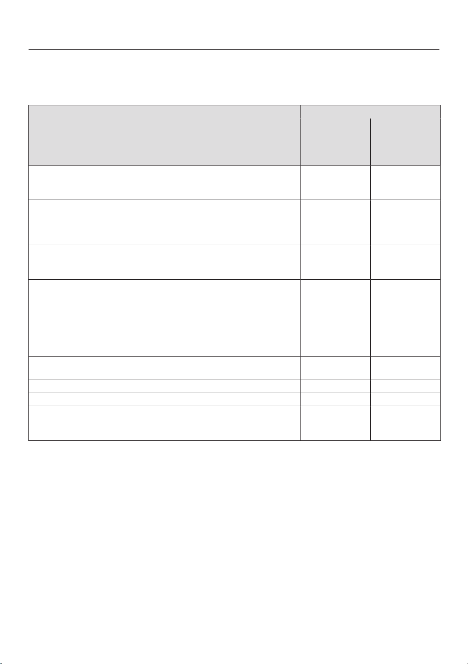
Setting ranges for the power levels
46
The hob is programmed with 9power levels at the factory. If you wish to fine-tune a
setting, you can extend the power level range to 17power levels (see “Adjusting
settings”).
Setting range
Factory set-
ting
(9power
levels)
Extended set-
ting
(17power
levels)
Melting butter
Melting chocolate
Dissolving gelatine
1–2 1–2.
Warming up small quantities of liquid
Keeping warm food which sticks easily
Cooking rice or porridge
Defrosting vegetables frozen in a block
2–4 2–3.
Warming up liquid and semi-solid food
Steaming fruit
Simmering potatoes (cookware with lids)
4–6 3.–5.
Making omelettes or lightly fried eggs
Gently frying meat patties
Steaming fish and vegetables
Cooking dumplings and dried pulses
Defrosting and reheating frozen food
Thickening sauces, e.g. Hollandaise
Pancakes
5–7 4.–7.
Gently frying (without overheating the fat) fish, escalopes, saus-
ages, fried eggs, etc.
6–8 6–7.
Cooking hash browns, pancakes, etc. 7–8 7–8.
Frying, e.g. chips 9 8.–9
Boiling large quantities of water
Bringing to the boil
Searing large quantities of meat
9–Booster 8.–Booster
These settings should only be taken as a guide. The power of the induction coils will vary de-
pending on the size and material of the cookware. For this reason, the power levels may
need to be adjusted slightly to suit your cookware. As you use the hob, you will get to know
which settings suit your cookware best. When using new cookware that you are not familiar
with, set the power to one level below the one specified.

Good to know
47
Hob
How induction hobs work
An induction coil is located under each
induction cooking zone. The coil creates
a magnetic field that reacts directly with
the base of the pan and heats it up. The
cooking zone itself is heated up indir-
ectly by the heat given off by the pan.
An induction cooking zone only works
when a piece of cookware with a mag-
netic base is placed on it (see “Good to
know – Cookware”). The hob automatic-
ally recognises the size of the cookware.
Noises
When using induction cooking zones,
the following noises can occur in the
cookware, depending on what it is made
of and how it has been constructed:
Buzzing on the higher power levels. This
will decrease or cease altogether when
the power level is reduced.
If the cookware base is made of layers
of different materials (e.g. in a sand-
wiched base), it might emit a crackling
sound.
Whistling might occur if linked cooking
zones (see “Operation – Booster”) are
being used at the same time, and the
cookware items also have bases made
of layers of different materials (e.g.
sandwiched base).
You might hear a clicking sound from
the electronic switches, especially at
lower power levels.
A whirring sound, when the cooling fan
comes on. This switches on to protect
the electronic module when the hob is
being used intensively. The cooling fan
may continue to run after the hob has
been switched off.
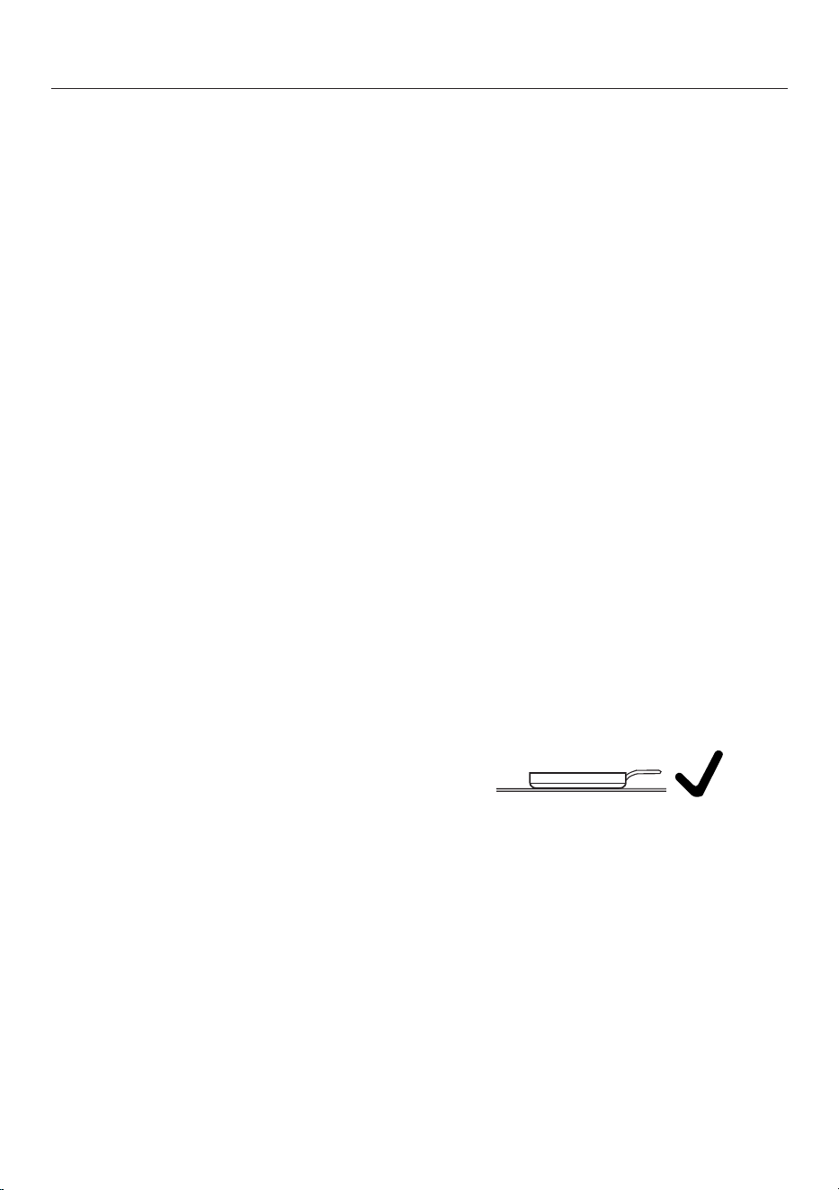
Good to know
48
Pans
Suitable cookware
- Stainless steel cookware with a mag-
netic base
- Enamelled steel cookware
- Cast iron
Please be aware that the properties of
the cookware base can affect the even-
ness with which the food heats up (e.g.
when making pancakes). The base of
the pan must be able to distribute the
heat evenly. Cookware with a base
made from multilayer material (sand-
wich or encapsulated base) is ideal in
this case.
Unsuitable pans.
- stainless steel pans without a mag-
netic base
- aluminium or copper pans
- glass, ceramic or earthenware pots
and pans
Testing pans
To test whether a pan is induction-com-
patible, hold a magnet to the base of the
pan. If the magnet sticks, the pan is
generally suitable.
Cookware tips
- Position the cookware as centrally as
possible on the relevant cooking
zone/cooking area.
- To make optimum use of the cooking
zones, choose cookware with a suit-
able base diameter (see “Familiarisa-
tion – Cooking zone data”). If a pan is
too small, it will not be recognised.
- Use only pots and pans with smooth
bases. Rough bases can scratch the
ceramic glass.
- Always lift cookware to move it. This
will help prevent scratching. If any
scratches do appear as a result of
cookware being pushed around, this
will not affect the function of the hob.
These scratches are normal signs of
use and are not grounds for making a
complaint.
- Please note that the cookware dia-
meter quoted by manufacturers often
refers to the maximum diameter or
diameter of the top rim. The diameter
of the base (generally smaller) is more
important.
- Where possible, use cookware with
vertically straight sides. If an item of
cookware has angular sides, induction
also acts on the sides of the item of
cookware. The sides of the item of
cookware may discolour or the coat-
ing may peel off.
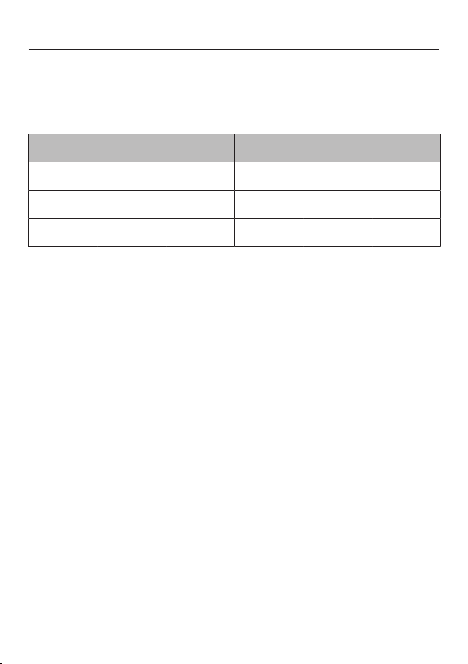
Good to know
49
Vapour extraction
How the vapour extraction works
What happens to the air after extraction varies depending on the type of operation
selected:
Air guidance Grease filter Duct Charcoal filter
Out of the
building
Back into the
kitchen
Extraction
mode
x x - x -
Guided recir-
culation mode
x x x - x
Plug&Play
mode
x - x - x
Extraction mode
The air drawn in is cleaned by the grease filter and directed outside through a vent-
ilation gap. The necessary accessories are available from Miele.
Guided recirculation mode
The air is drawn in and cleaned first by the grease filter and then by a charcoal filter.
It is then directed into the recirculation box via a duct. The recirculation box feeds
the air back into the kitchen. The necessary accessories are available from Miele.
Plug&Play mode
The air is drawn in and cleaned first by the grease filter and then by a charcoal filter.
The air is then routed through the base unit via a cut-out in the plinth and back into
the kitchen.
A summary of the operating options and the KMDA variants that offer them can be
found in “Installation – Operating options”.
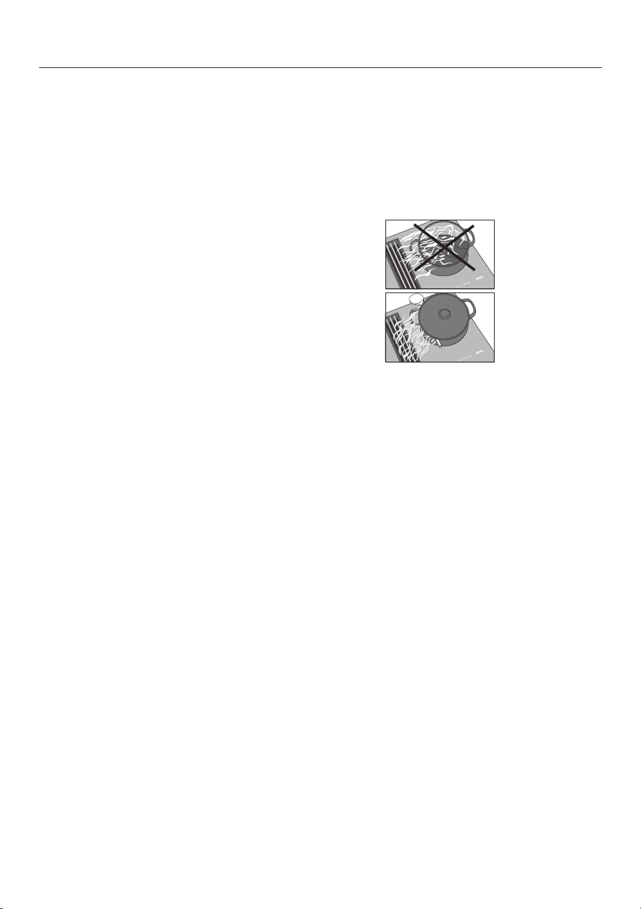
Good to know
50
Operating hours counter
The number of hours that the vapour ex-
traction has been used for is stored in
memory.
When the grease filter symbol or the
charcoal filter symbol (KMDA 7876
FL-U only) lights up, the operating hours
counters are signalling that the filters
need to be cleaned or replaced. Further
information about cleaning and chan-
ging the filters and resetting the operat-
ing hours counters can be found under
“Cleaning and care”.
Air extraction tips
Tip: For light to heavy cooking vapours
and odours, select from power levels 1
to 3 (9 with the extended power levels).
For short periods of very strong vapours
and odours, e.g. whilst searing meat, se-
lect the B Booster setting.
Tip: To help extract air effectively with
pans over 15cm high, place a wooden
spoon between the lid and the pan.

Adjusting settings
51
Accessing programming mode
The hob is switched off.
Touch and hold the and sensor
controls until the + sensor control
lights up and appears in the timer
display.
After a few seconds :(Programme
01) will flash alternately with
:(Code) in the timer display.
Setting the programme
For a two-digit programme number you
need to first set the tens position.
While the programme is visible in the
display (e.g. :), press the +sensor
control repeatedly until the number
for the programme you want appears
in the display or touch the appropriate
number on the numerical display.
Setting the code
While the code is visible in the display
(e.g. :), press the +sensor control
repeatedly until the number for the
code you want appears in the display
or touch the appropriate number on
the numerical display.
Saving the settings
Whilst the programme is visible in the
display (e.g.:), touch the
sensor control until the displays go
out.
To avoid saving the settings
While the code is showing in the dis-
play (e.g.:) touch the sensor
until the indicators go out.
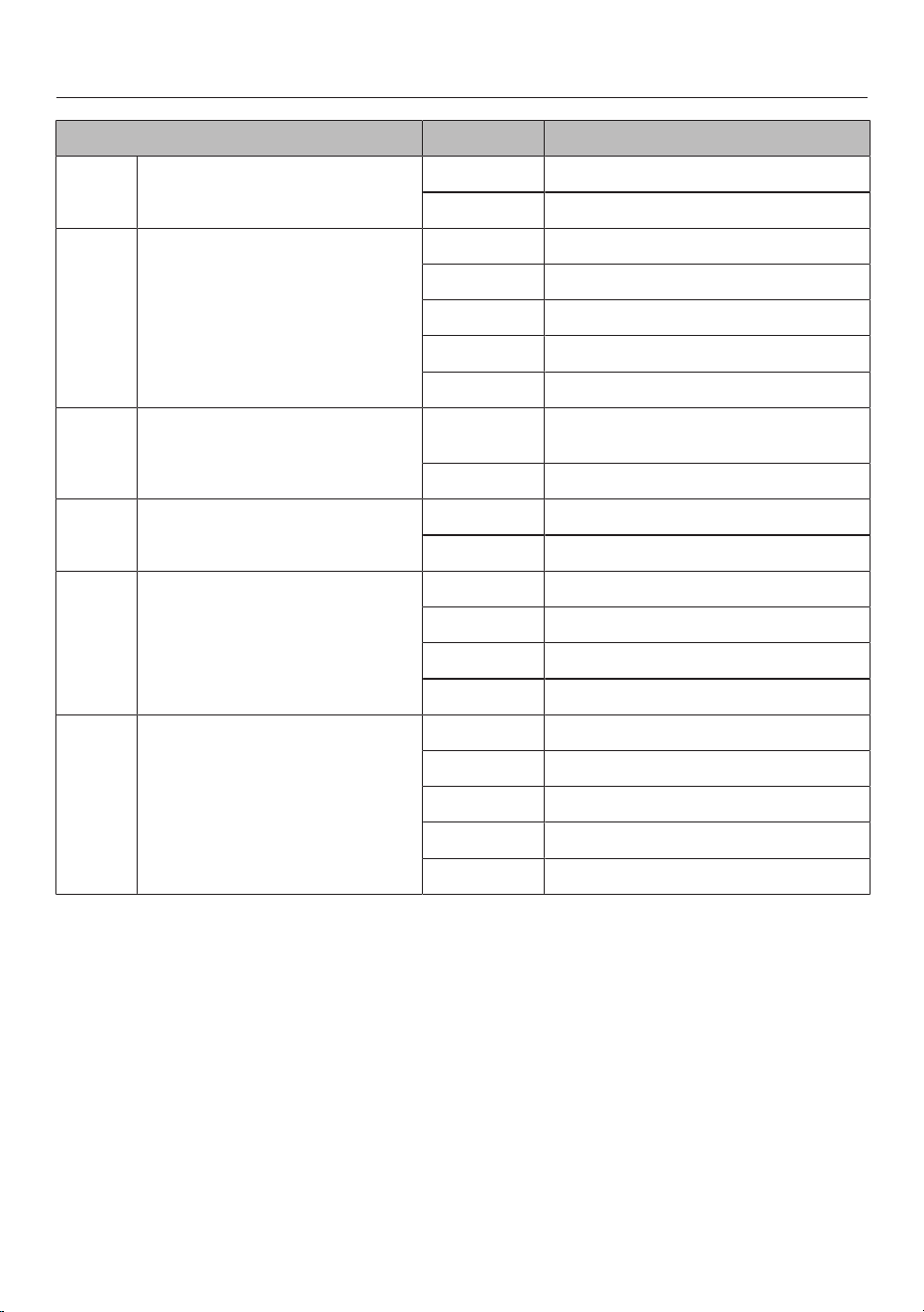
Adjusting settings
52
Programme
1
Code
2
Settings
P:01
Demo mode
C:00
Demo mode off
C:01 Demo mode on
3
P:02 Power management
4
C:00
Off
C:01
3680W
C:02
3000W
C:03
2000W
C:04
1000W
P:03
Factory default settings
C:00
Do not restore factory default set-
tings
C:01 Restore factory default settings
5
P:04
Power level setting range
C:00
9 power levels + Booster
C:01 17 power levels + Booster
6
P:06
Audible tone when a sensor
control is touched
C:00 Off
7
C:01
Quiet
C:02
Medium
C:03
Loud
P:07
Timer buzzer
C:00
Of
C:01
Quiet
C:02
Medium
C:03
Loud
C:04
Maximum volume
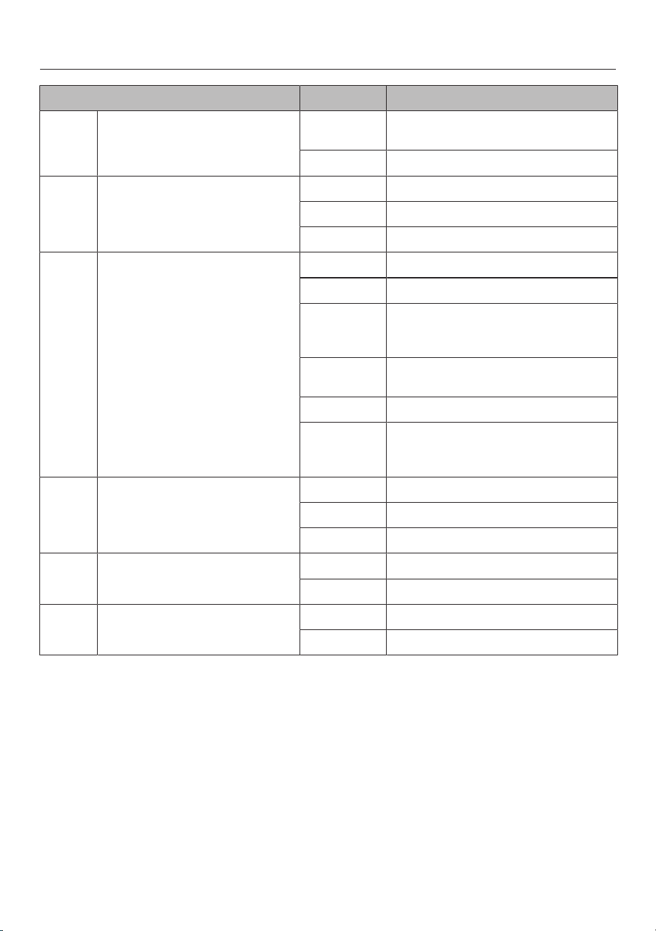
Adjusting settings
53
Programme
1
Code
2
Settings
P:08
System lock
C:00
System lock can only be activated
manually
C:01
System lock activated automatically
P:09
Maximum operating time
C:00
Safety setting 0
C:01
Safety setting 1
C:02
Safety setting 2
P:10
WiFi registration
C:00
Not active/deactivated
C:01
Active but not configured
C:02
Active and configured (cannot be se-
lected; displays whether connection
was successful)
C:03
Connection possible via WPS push
button
C:04
WiFi reset to default (C:00)
C:05
Direct WiFi connection of hob and
external cooker hood without Miele
app (Con@ctivity)
P:12
Sensor controls reaction speed
C:00
Slow
C:01
Normal
C:02
Fast
P:15
Permanent pan recognition
C:00
Permanent pan recognition off
C:01
Permanent pan recognition on
P:16
Con@ctivity of built-in vapour
extraction
C:00 Con@ctivity off
8
C:01
Con@ctivity on
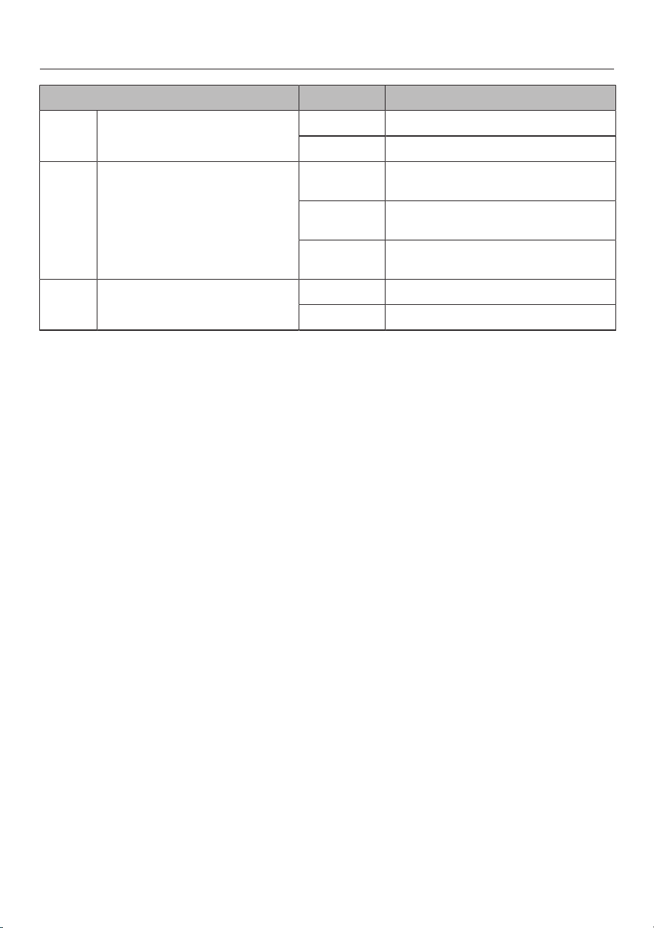
Adjusting settings
54
Programme
1
Code
2
Settings
P:17
Vapour extraction operating
mode
C:00
9
Recirculation mode
C:01
9
Extraction mode
P:18 Start settings of Con@ctivity
10
C:00
Always start with Con@ctivity deac-
tivated
C:01
Always start with
Con@ctivity activated
C:02
Start with the most recently set
Con@ctivity state
P:19
Number of vapour extraction
power levels
C:00
3 power levels + Booster
C:01
9 power levels + Booster
1
Programmes not shown here have no allocation.
2
The factory default setting is shown in bold.
3
After the hob has been switched on, appears in the timer display for a few seconds.
4
The total output of the hob may be reduced in order to meet the local network provider’s
requirements.
5
The settings for the P:17 operating mode of the vapour extraction will not be reset to the
factory default settings.
6
In the text and tables, the extended power levels are shown with a dot after the number.
7
The confirmation tone of the On/Offsensor control cannot be switched off.
8
Plug&Play mode: Con@ctivity is required for correct operation.
9
Factory-set code:
KMDA 7876 FL-U: C:00
KMDA 7876 FL-A: C:01
10
The settings only take effect if Con@ctivity has been activated in the P:16 programme.
Cleaning and care
55
Safety notes on cleaning and care
Risk of burns due to hot surfaces.
All parts of the hob may be hot after use.
Switch the hob off.
Allow the hob to cool down before cleaning it.
All surfaces could be discoloured or damaged if unsuitable cleaning
agents are used or if residues from suitable cleaning agents are
heated on the hob. All surfaces are susceptible to scratching.
Allow the surfaces to cool down before cleaning the hob.
Remove all cleaning agent residues immediately.
Never use abrasive sponges or cleaning agents.
Risk of fire due to soiled grease filter.
Grease collected in the grease filter can ignite.
Clean the grease filter regularly.
Risk of injury due to the fan motor.
The fan motor rotates while the vapour extraction is active.
Switch the hob off.
Wait until the run-on cycle is finished, if applicable.
Do not use a steam cleaner to clean the hob.
Do not use pointed objects for cleaning.
Cosmetic products, especially sunscreen, and hand disinfectants
can leave stains on matt glass surfaces.
If cosmetic products come into contact with a matt glass surface,
remove the residue immediately with hot water, washing-up liquid
and a clean microfibre cloth.
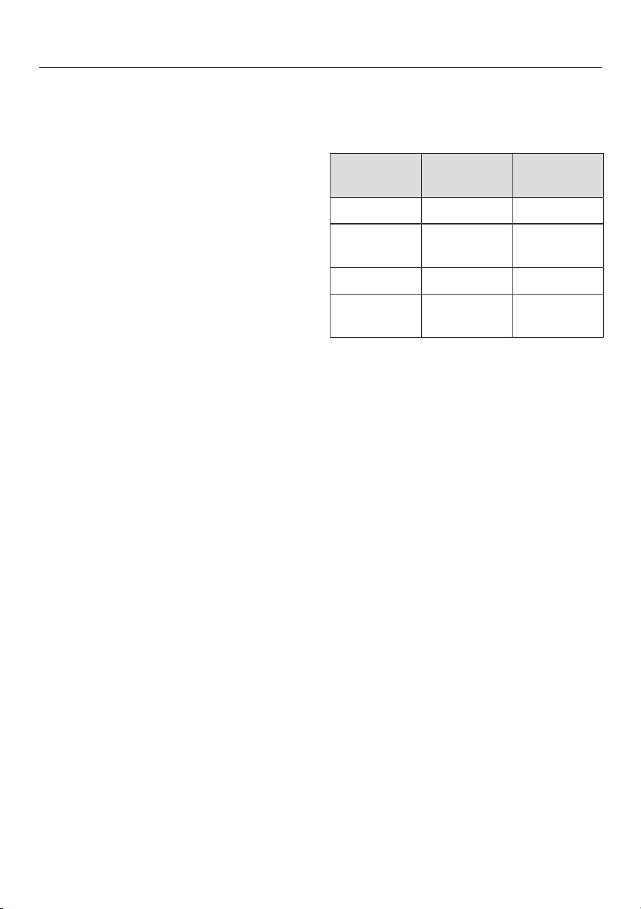
Cleaning and care
56
When to clean
Clean the hob after every use.
Cleaning the ceramic glass sur-
faces
Removing light soiling
Clean the entire ceramic surface of
the hob with a damp, soft cloth and a
solution of water and a little washing-
up liquid. Please follow the cleaning
agent manufacturer’s instructions.
Removing stubborn soiling
Remove any coarse soiling with a
damp cloth and more stubborn soiling
with a scraper suitable for use on
glass.
Clean the ceramic glass surface with
the Miele ceramic and stainless steel
cleaner (see “Optional accessories –
Cleaning and care products”), with a
proprietary ceramic glass cleaner or
scouring liquid. Please follow the
cleaning agent manufacturer’s in-
structions.
Finishing the cleaning process
Remove all cleaning agent residues
with a damp cleaning cloth.
Dry the ceramic surface of the hob
after cleaning.
Dishwasher-safe components
You can clean the removable compon-
ents of your hob as follows:
Dish-
washer
By hand
Cover grille X X
Grease fil-
ter
X X
Drip tray X X
Cleaning
flap
X X
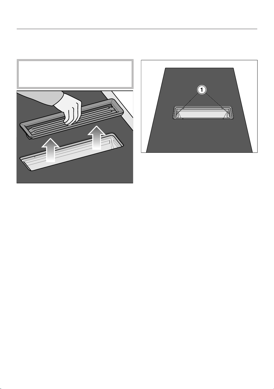
Cleaning and care
57
Cover grille
Removing the cover grille
The cover grille could be damaged.
Pull the cover grille vertically out of
the top of the KMDA.
Take hold of the cover grille in the
centre of the bars.
Pull the cover grille vertically upwards.
Cleaning the cover grille by hand
Clean the cover grille with a soft nylon
brush in a mild solution of hot water
and a little washing-up liquid. Do not
use concentrated washing-up liquid.
Cleaning the cover grille in the dish-
washer
Place the cover grille upright in the
lower basket.
Use a standard household dishwasher
detergent.
Select a dishwasher programme with
a maximum wash temperature of
55°C.
Grease filter
Removing the grease filter
Remove the cover grille (see “Clean-
ing and care – Removing the cover
grille”).
Carefully remove the grease filter us-
ing the recessed grips (1). Ensure that
you do not tilt the grease filter.
Pour out any liquid which has collec-
ted at the bottom of the grease filter.
Cleaning the grease filter by hand
Clean the grease filter with a soft
nylon brush in a mild solution of hot
water and a little washing-up liquid.
Do not use concentrated washing-up
liquid.
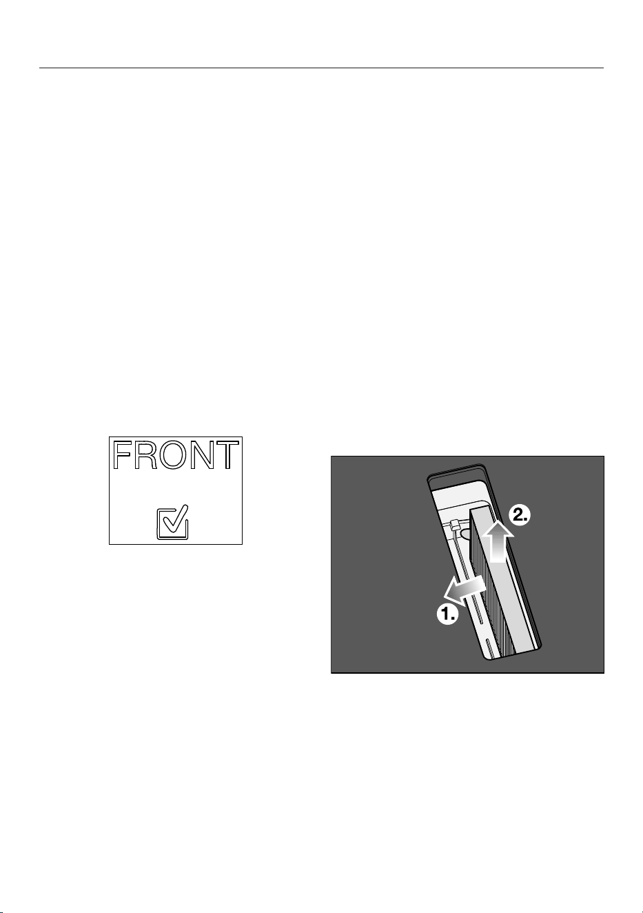
Cleaning and care
58
Cleaning the grease filter in the dish-
washer
Depending on the detergent used,
cleaning the grease filter in a dish-
washer can cause permanent discolour-
ation to the internal surfaces of the fil-
ter. However, this will not affect the
functioning of the grease filter in any
way.
Place the grease filter with its base fa-
cing upwards in the lower basket. En-
sure the spray arm is not obstructed.
Use a standard household dishwasher
detergent.
Select a dishwasher programme with
a maximum wash temperature of
65°C.
Fitting the grease filter
The grease filter has a symbol on the
front.
Insert the grease filter so that the
symbol is pointing towards the front
of the worktop.
Resetting the grease filter operating
hours counter
After cleaning the grease filter, the oper-
ating hours counter needs to be reset.
Touch the sensor for 3seconds.
The sensor will go out.
Charcoal filter (only
KMDA 7876 FL-U)
Replacing the charcoal filter (only
KMDA 7876 FL-U)
The charcoal filter must be replaced
after 120operating hours. The sensor
control will light up.
The charcoal filters listed here are suit-
able for the KMDA variants covered by
these operating instructions:
- DKF 35-P
- DKF 35-S
Remove the cover grille (see “Clean-
ing and care – Removing the cover
grille”).
Remove the grease filter (see “Clean-
ing and care – Removing the grease
filter”).
Remove the charcoal filter.
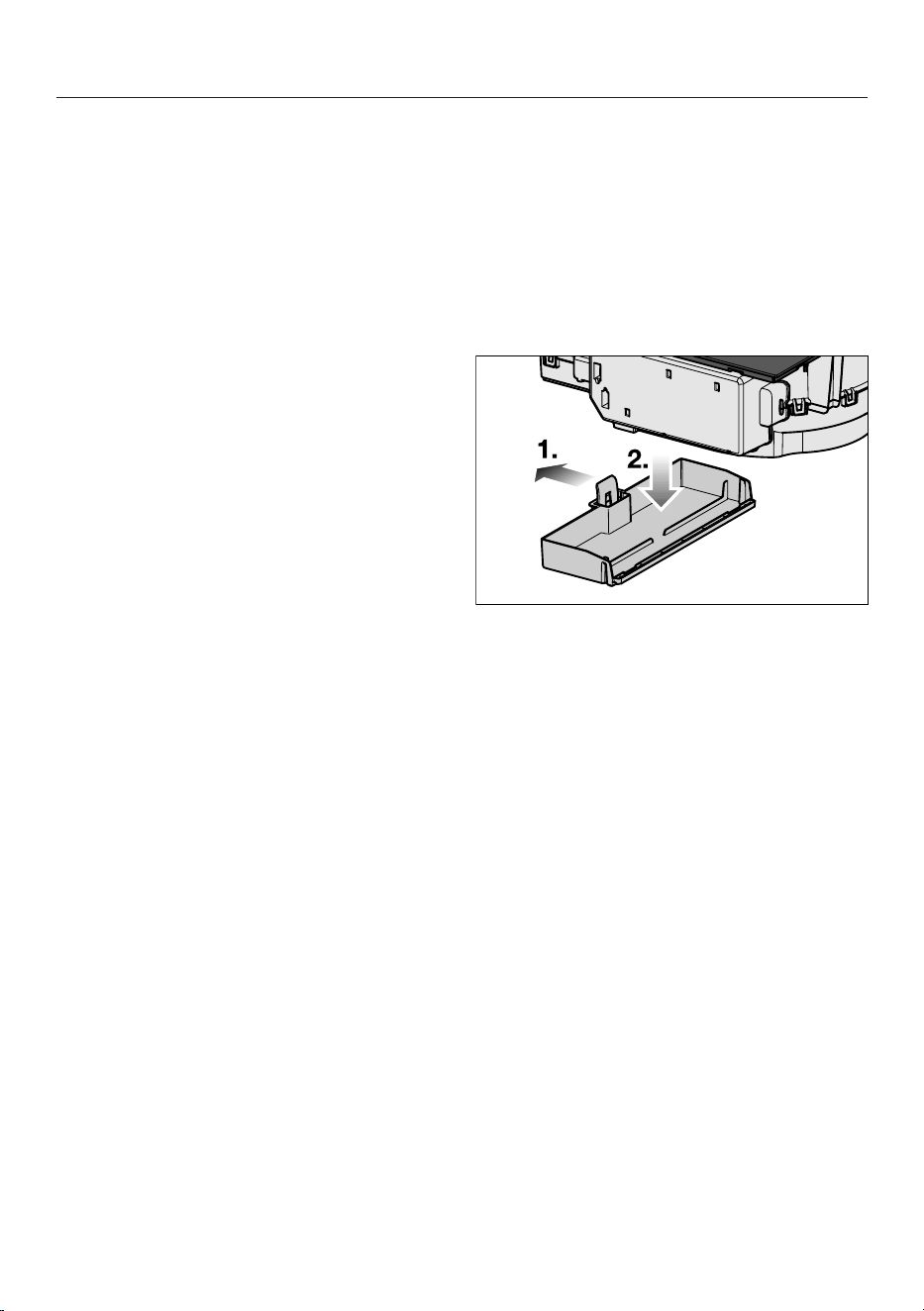
Cleaning and care
59
Resetting the charcoal filter operating
hours counter (only
KMDA 7876 FL-U)
The operating and installation instruc-
tions supplied with the recirculation box
state that the operating hours counter
for the charcoal filter needs to be activ-
ated. This is not necessary here.
The charcoal filter symbol also ap-
pears when the vapour extraction is op-
erated using extraction mode.
Touch the sensor control for
3seconds.
The sensor control will go out.
Cleaning the vapour extraction
drip tray
Clean the drip tray if liquid from food
being spilled or boiling over has got into
the vapour extraction unit.
Remove and clean the grease filter as
described in “Cleaning and care –
Grease filter”.
Push the plastic bracket to the left
until the drip tray can be pulled down-
wards.
Pour out the liquid.
Clean and dry the drip tray.
Also clean and dry accessible areas
inside of the vapour extraction unit.
Fasten the drip tray back onto the
casing.
Replace the grease filter and refit the
cover grille.
Cleaning inside the vapour ex-
traction casing
Remove the grease filter (see “Clean-
ing and care – Removing the grease
filter”).
Clean off any accessible oil or fat
build-up from the casing.
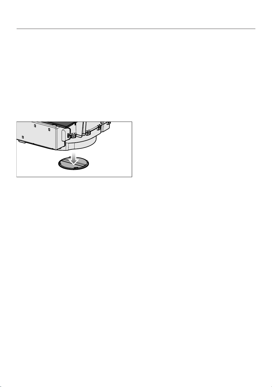
Cleaning and care
60
Cleaning the inside of the fan
unit
Clean the inside of the fan unit if liquid
from food being spilled or boiling over
has got into the vapour extraction unit.
Clean the vapour extraction drip tray
(see “Cleaning and care – Cleaning
the vapour extraction drip tray”).
Place a container under the cleaning
flap to catch the liquid.
Turn the cleaning flap to the left.
Let the liquid run out.
Turn the cleaning flap to the right as
far as it will go.
Unsuitable cleaning agents
To avoid damaging the surfaces of the
appliance, do not use:
- Cleaning agents containing soda, al-
kalines, ammonia, acids or chlorides
- Stain and rust removers
- Powder cleaners and cream cleaners
- Cleaning agents containing solvents
- Dishwasher cleaning agents
- Grill and oven sprays
- Hard, abrasive brushes
- Eraser stain remover blocks
Troubleshooting
61
Messages in the display
Problem Cause and remedy
will flash alternately
with in the timer dis-
play and a tone will
sound.
The hob is incorrectly connected.
Disconnect the hob from the mains electricity sup-
ply.
Contact the Customer Service Department. The hob
must be connected to the mains according to the
wiring diagram.
The symbol lights up or
flashes alternately with
the set power level or
in one of the cooking
zone indicators.
No cookware is present on the cooking zone.
Unsuitable cookware is present on the cooking zone.
The diameter of the base of the cookware is too small
Suitable cookware has been removed from the cook-
ing zone.
If no cookware or unsuitable cookware is placed on
the cooking zone, the cooking zone will switch off
automatically after 3minutes.
Place a suitable item of cookware on the cooking
zone within 3minutes.
will go out. The cooking process starts/continues
with the previously selected settings.
If you are using a different item of cookware and/or
food, modify the settings.
After the hob has been
switched on, or after
touching a sensor,
appears in the timer dis-
play for a few seconds.
The system lock is activated.
Deactivate the system lock (see “Operation – Deac-
tivating the system lock”).
The safety lock is activated.
Deactivate the safety lock (see “Operation – Deac-
tivating the safety lock”).
After the hob has been
switched on, appears
briefly in the timer dis-
play. The cooking zones
do not heat up.
The hob is in demo mode.
There is cookware on the hob.
Switch the hob on.
Then touch the and sensor controls at the same
time until flashes alternately with in the timer
display.
Troubleshooting
62
Problem Cause and remedy
The hob has switched off
automatically. When the
hob is switched back on,
appears above the On/
Off sensor control.
One or more of the sensor controls are covered, e.g.
by finger contact, food boiling over or an object.
Clean off any soiling and/or remove the object (see
“Familiarisation – Safety switch-off”).
A message not listed in
this table is appearing in
the timer display.
There is an electronic module fault.
Disconnect the power supply to the hob for approx.
1minute.
If the problem persists after the power supply has
been restored, please contact the Customer Service
Department.
Troubleshooting
63
Unexpected behaviour
Problem Cause and remedy
Power level9 is auto-
matically reduced if you
also set power level9 for
the connected cooking
zone.
Operating both zones at power level9 exceeds the
permitted maximum power for the two zones.
Use a different cooking zone.
A cooking zone switches
off automatically.
It has been operated for too long.
Switch the cooking zone back on (see “Familiarisa-
tion – Safety switch-off”).
The cooking zone is not
working in the usual way
with the set power level.
The overheating protection mechanism has been ac-
tivated.
Allow the hob to cool down.
Rectify the causes of the overheating (see “Familiar-
isation – Overheating protection”).
Check that the hob is working.
If the problem occurs again, contact the Customer
Service Department.
A cooking zone or the
whole hob switches off
automatically.
The overheating protection mechanism has been ac-
tivated.
Allow the hob to cool down.
Rectify the causes of the overheating (see “Familiar-
isation – Overheating protection”).
Check that the hob is working.
If the problem occurs again, contact the Customer
Service Department.
The Booster level has
deactivated early auto-
matically.
The overheating protection mechanism has been ac-
tivated.
Allow the hob to cool down.
Rectify the causes of the overheating (see “Familiar-
isation – Overheating protection”).
Check that the hob is working.
If the problem occurs again, contact the Customer
Service Department.
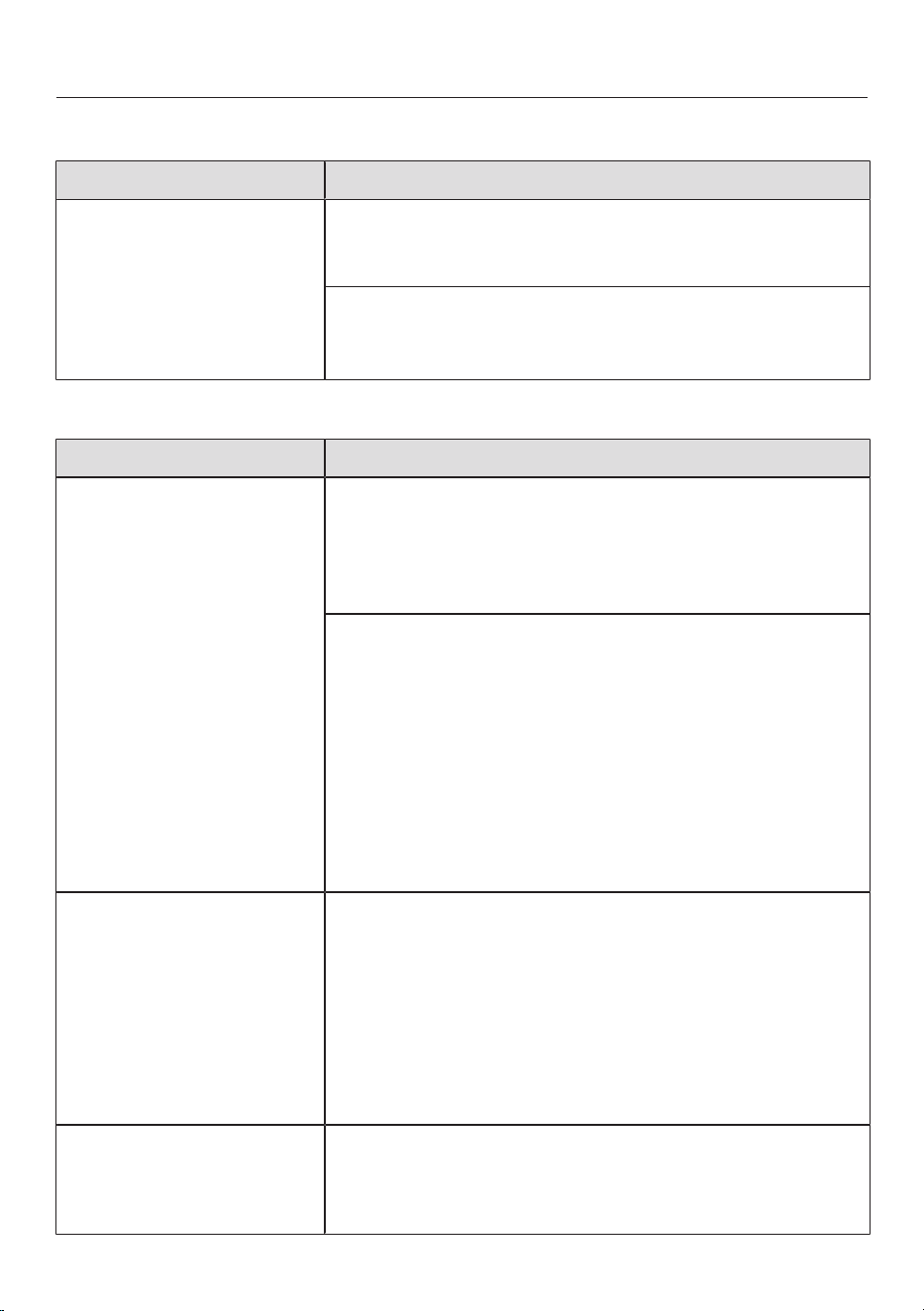
Troubleshooting
64
Unsatisfactory results
Problem Cause and remedy
The food in the pan does
not heat up when the
Auto heat-up function is
switched on.
A large amount of food is being heated up.
Start cooking at the highest power level and then
turn down to a lower one manually later on.
The pan is not conducting heat properly.
Use a different pot or pan which conducts heat
properly.
General problems or technical faults
Problem Cause and remedy
The hob or cooking
zones will not switch on.
There is no power to the hob.
Check whether the circuit breaker has tripped. Con-
tact a qualified electrician or the Miele Customer
Service Department (for the minimum fuse rating,
see data plate).
There may be a technical fault.
Disconnect the hob from the electricity supply for
approx. 1minute. To do this:
– tripping the relevant mains fuse or screwing the
fine-wire fuse out completely, or
– switching off at the residual current device.
If the hob will still not turn on after resetting the trip
switch in the fuse box or the residual current device,
contact a qualified electrician or the Miele Customer
Service Department.
A smell and vapours are
given off when the new
appliance is being used.
The metal components have a protective coating.
When the appliance is used for the first time, this
causes a smell and possibly also vapour. The material
from which the induction coils are made also gives off
a smell in the first few hours of operation. With each
subsequent use, the odour is reduced until it disap-
pears completely. The smell and any vapours given off
do not indicate a faulty connection or appliance and
they are not hazardous to health.
An operating noise can
be heard after the appli-
ance has been switched
off.
The cooling fan runs until the hob has cooled down
and then switches off automatically.
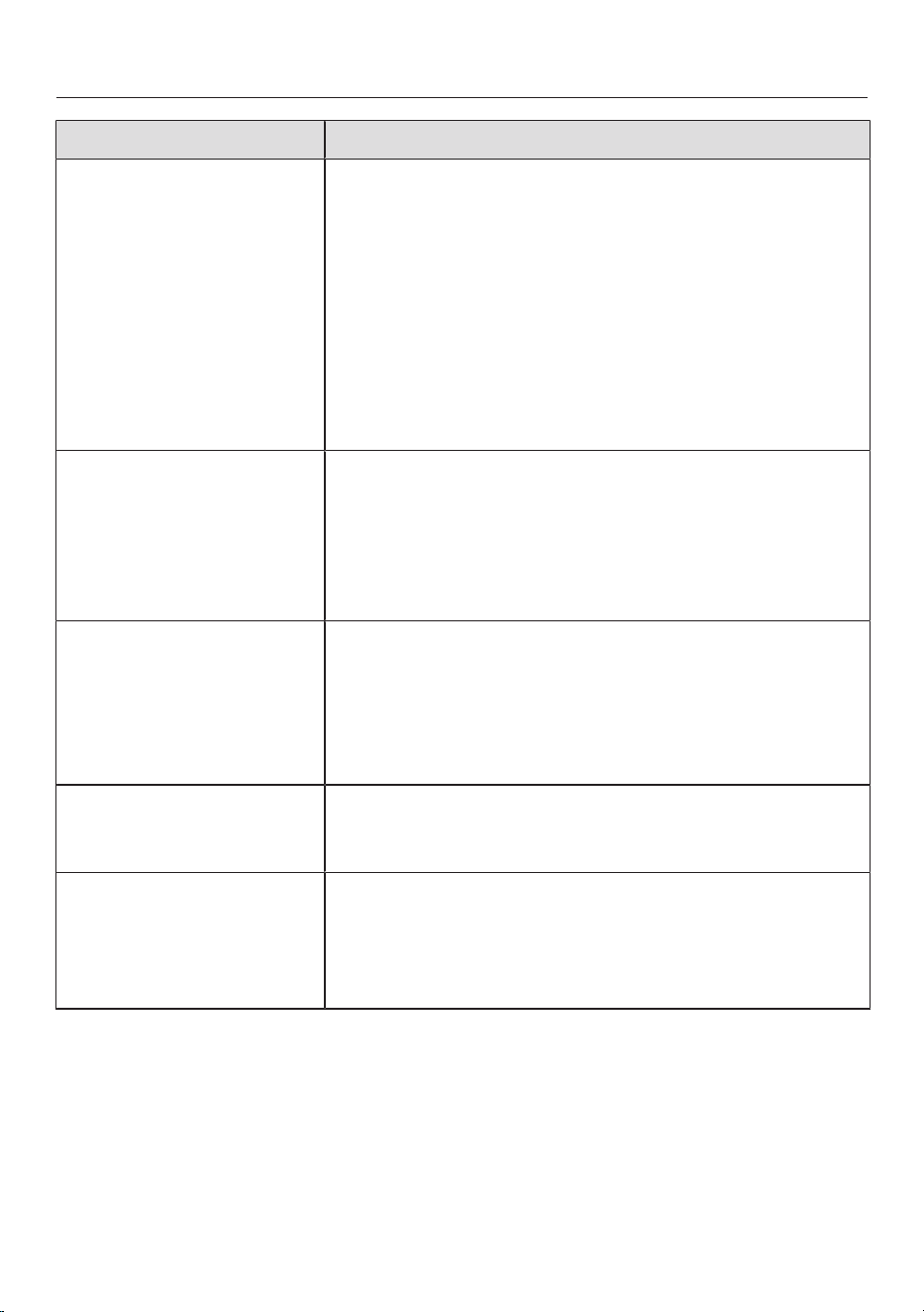
Troubleshooting
65
Problem Cause and remedy
Liquid has got into the
vapour extraction.
Due to boiling over or spillage, liquid has made its way
through the cover grille into the vapour extraction.
The base of the grease filter and the drip tray can hold
approx. 800ml of liquid in total.
Switch the vapour extraction off.
Clean the grease filter, the drip tray, the inside of the
casing and the fan motor compartment (see “Clean-
ing and care”).
KMDA 7876 FL-U only: replace the charcoal filter
(see “Cleaning and care – Replacing the charcoal fil-
ter”).
Extraction power has de-
creased. Extraction
noise has increased.
Objects (e.g. a cloth) have been drawn into the vapour
extraction.
Switch the vapour extraction off.
Remove the grease filter (see “Cleaning and care –
Removing the grease filter”).
Remove any objects from the grease filter.
The sensor control is
lit up.
The charcoal filter must be replaced.
Replace the charcoal filter (see “Cleaning and care –
Replacing the charcoal filter”).
Reset the operating hours counter (see “Cleaning
and care – Resetting the charcoal filter operating
hours counter”).
The sensor control is
lit up.
The grease filter must be cleaned.
Clean the grease filter as described in “Cleaning and
care – Grease filter”.
The sensor control
does not light up.
The Con@ctivity function of the integrated vapour ex-
traction is permanently deactivated.
Activate the Con@ctivity function of the integrated
vapour extraction in the programming (see “Adjust-
ing settings”).
After sales service
66
Information to help you rectify faults yourself and about Miele spare parts can be
found at www.miele.com/service.
Contact in the event of a fault
In the event of a fault which you cannot remedy yourself, please contact your Miele
dealer or Miele Customer Service.
You can book a Miele Customer Service call-out online at www.miele.com/ser-
vice.
Contact information for Miele Customer Service can be found at the end of this
document.
Please quote the model identifier and serial number of your appliance (SN) when
contacting Miele Customer Service. These can be found on the data plate or see
“Operation – Hob data”.
Data plate
Stick the extra data plate supplied with the appliance here. Make sure that the
model number matches the one specified on the back cover of this document.
Warranty
For information on the appliance warranty specific to your country please contact
Miele. See back cover for address.
In the UK, your appliance warranty is valid for 2 years from the date of purchase.
However, you must activate your cover by calling 0330 160 6640 or registering on-
line at www.miele.co.uk.
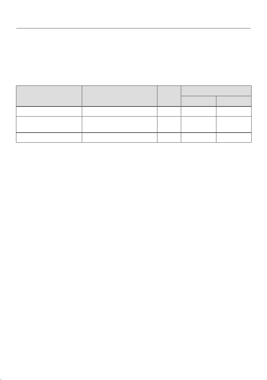
After sales service
67
Note for test institutes
Test food acc. to EN60350-2
9 power levels are programmed at the factory.
For testing in accordance with the above standard, programme the hob to the ex-
tended power level setting (see “Adjusting settings”).
Test food
Pan base (mm)
Lid
Power level
Pre-heat Cook
Heating oil up 150 No – 1–2
Pancakes 180
(Sandwich base)
No 9 5.–7.
Frying deep frozen chips According to the standard No 9 9

Optional accessories
68
Cookware
Miele offers a wide range of cookware.
These have all been optimised for Miele
appliances in terms of functionality and
dimensions. Detailed information is
provided on the Miele website.
Charcoal filter
Only the Miele charcoal filters listed
here are suitable for the KMDA variants
covered by these operating instructions:
- DKF 35-P
- DKF 35-S
Further accessories for vapour
extraction
Further accessories, e.g. for air guid-
ance, can be ordered from the Miele on-
line shop. Detailed information is
provided on the Miele website.
Cleaning and care products
Ceramic and stainless steel hob
cleaner 250ml
Removes heavy soiling, limescale de-
posits and aluminium residues.
Microfibre cloth
For removing finger marks and light soil-
ing.
Installation
*INSTALLATION*
69
Safety notes for installation
Risk of damage from incorrect installation.
Incorrect installation can cause damage to the hob.
The hob must only be installed by a qualified specialist.
Risk of electric shock from mains voltage.
Incorrect connection to the mains supply may result in an electric
shock.
The hob must be connected to the electrical supply by a qualified
electrician only.
Damage from falling objects.
Take care not to damage the hob when fitting wall units or a cooker
hood above it.
Fit the wall units and the cooker hood before the hob.
Dismantling the hob for service purposes may damage the sealing
strip underneath the edge of the hob.
Always replace the sealing strip before reinstalling.
The hob must not be installed over a fridge, fridge-freezer, freezer,
dishwasher, washing machine, washer-dryer or tumble dryer.
This hob may only be installed above a cooker or oven if they have
a built-in cooling fan.
A gas hob must not be installed next to this hob.
After installation, ensure that nothing can come into contact with
the connection cable and that it is without hindrance.
The electrical cable may not come into contact with any moving
kitchen component (e.g. a drawer) or be subject to mechanical ob-
struction which could damage it.
The veneer or laminate coatings of worktops (or adjacent kitchen
units) must be treated with 100°C heat-resistant adhesive which will
not dissolve or distort. Any backmoulds must be of heat-resistant
material.
The crossbeams in front of the top area of the housing unit rear
wall must be removed for installation.

Installation
*INSTALLATION*
70
The hob must be installed such that the drip tray and the cleaning
flap are easily accessible and can be removed for cleaning.
The air duct is laid behind the housing unit rear wall. The rear wall
must be removable for maintenance purposes.
The minimum plinth height of the KMDA 7876 FL-U is:
- Extraction mode: no minimum plinth height required
- Guided recirculation mode: 100mm
- Plug&Play mode: 25mm
The exhaust air drawn into the vapour extraction may only be
routed through the base unit and back into the room in Plug&Play
mode. In extraction mode and in guided recirculation mode, the ex-
haust air must be routed outside through ducting (extraction mode)
or back into the room through the recirculation box (guided recircula-
tion mode).
Remember to maintain the minimum safety distances (see “In-
stallation – Safety distances”).

Installation
*INSTALLATION*
71
Additional safety notes for extraction mode
The appliance must not be connected to a chimney or flue which is
in use. Neither should it be connected to ducting which ventilates
rooms with fireplaces.
If exhaust air is to be extracted into a chimney or ventilation duct
no longer used for other purposes, seek professional advice.
Exhaust ducting must be of non-inflammable material. Suitable
material is available from Miele specialist dealers or the Miele Spares
Dept.

Installation
*INSTALLATION*
72
Additional safety notes for Plug&Play mode
U value
Plug&Play operation is possible in younger or renovated buildings. If the adjacent
wall or the floor is in contact with the ground or the outside air, it must have a heat
transfer coefficient (U value) of ≤ 0.5W/(m²K).
Material Material thickness U value
(as of 1995)
Solid wall
(vertical coring brick, floating brick or com-
parable porous or highly perforated materi-
als)
≥ 30cm 0.5
Solid timber wall
(e.g. log cabin/prefabricated house). Timber
frame or timber panel wall with insulating
filling
– 0.4
Passive house
(KfW 55, 40, 40 Plus)
– 0.15–0.2
The U values for other materials can be found on the websites of the German Fed-
eral Ministry for Economic Affairs and Climate Action and the German Federal Min-
istry of the Interior and Community.
If you have any other questions about your building, please contact a construction
expert or energy adviser.
The cross-section of the ventilation opening must be at least
425cm².
If ventilation grilles are to be inserted into the ventilation gaps, the
ventilation gaps must be larger than 425cm². The unobstructed
airflow of 425cm² is calculated by adding up the total area of vent-
ilation openings in the grilles.
The ventilation gaps must not be covered or blocked in any way.
They must also be regularly dusted.
The Plug&Play adapter included with the hob is required for opera-
tion in Plug&Play mode.
A template is required when installing the hob.
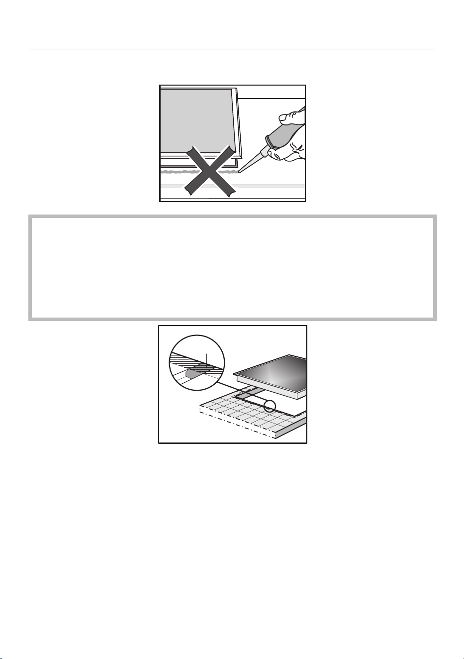
Installation
*INSTALLATION*
73
Additional safety notes for surface-mounted installation
Damage caused by incorrect installation.
Using sealant under the hob could result in damage to the hob and
the worktop if the hob ever needs to be removed.
Do not use sealant between the hob and the worktop.
The sealing strip under the edge of the hob provides a sufficient
seal for the worktop.
a
Grout lines and the hatched area underneath the hob frame
must be smooth and even. If they are not, the hob will not sit flush
with the worktop and the sealing strip underneath the hob will not
provide a good seal between the hob and the worktop.

Installation
*INSTALLATION*
74
Additional safety notes for flush-fit installation
Damage from unsuitable sealant.
Unsuitable sealant can damage natural stone.
For natural stone worktops and natural stone tiles, only use silicone
sealant that is specially formulated for natural stone. Follow the
manufacturer’s instructions.
The internal width of the base unit underneath the appliance must
be at least as wide as the inner worktop cut-out (see “Installation –
Building-in dimensions for flush-fit installation”), so that the hob is
easily accessible from underneath after installation and the casing
can be removed for maintenance. If the underside of the hob is not
freely accessible after installation, any sealant used must be removed
to enable the hob to be lifted out of the cut-out should this be neces-
sary.
A flush-fit hob is suitable only for installation in natural stone (gran-
ite, marble), solid wood and tiled worktops. When using a worktop
made from any other material, please check first with the worktop
manufacturer that the material is suitable for installing a flush-fit hob.
- Natural stone worktops: the hob is set directly in the cut-out.
- Solid wood worktops, tiled worktops: the hob is secured inside the
cut-out with wooden battens. The battens must be provided on
site and are not included in the scope of delivery.
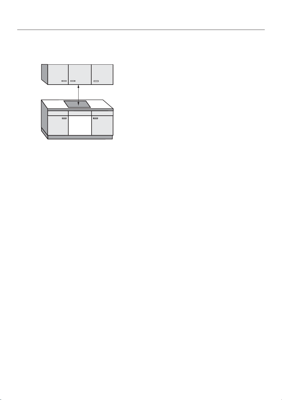
Installation
*INSTALLATION*
75
Safety distances
Safety distance above the hob
The following must be ensured between
the hob and the cooker hood above it:
- The safety distance specified by the
manufacturer of the cooker hood must
be maintained.
- When two or more appliances which
have different safety distances are in-
stalled together below a cooker hood,
the greatest specified safety distance
must be maintained.
If combustible objects are installed
above the hob (e.g. cabinets, utensil rail,
etc.), a minimum safety distance of
500mm must be maintained.
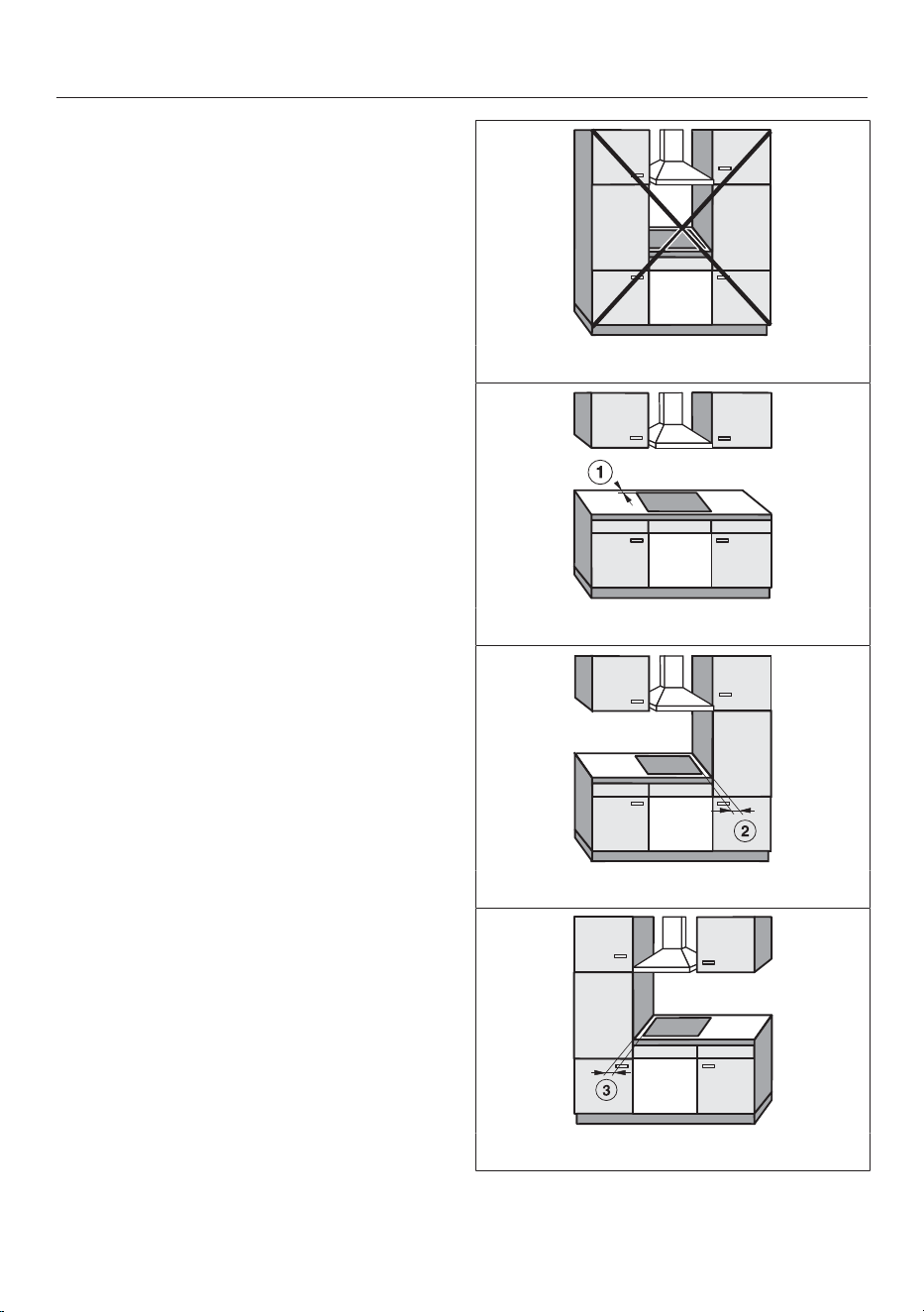
Installation
*INSTALLATION*
76
Safety distance behind and to the side
of the hob
The minimum safety distances shown
below must be maintained between the
appliance and a tall unit or wall:
- Between the back of the worktop
cut-out and the rear edge of the work-
top:
50mm
and
- On the right side between the
worktop cut-out and the closest adja-
cent piece of furniture (e.g. tall unit) or
a room wall:
50mm and on the opposite side a
minimum safety distance of 200mm
or
- On the left side between the work-
top cut-out and the closest adjacent
piece of furniture (e.g. tall unit) or a
room wall:
50mm and on the opposite side a
minimum safety distance of 200mm
Not permitted
Highly recommended
Not recommended
Not recommended
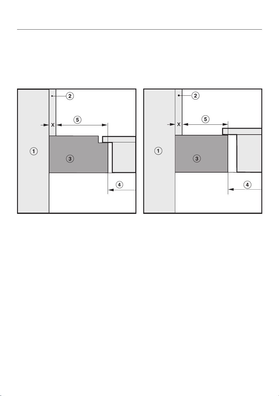
Installation
*INSTALLATION*
77
Safety distance from the niche cladding
If niche cladding is installed, a minimum safety distance must be maintained
between the worktop cut-out and the cladding. High temperatures can alter or
damage these materials.
Flush-fit installation Surface-mounted installation
a
Masonry
b
Dimensionx= thickness of the niche cladding material
c
Worktop
d
Worktop cut-out
e
Minimum safety distance to
combustible materials (e.g. wood) 50mm
non-combustible materials (e.g. metal, natural stone, ceramic tiles)
50mm – dimension x
Example: 15mm thick non-combustible niche cladding
50mm – 15mm = minimum safety distance of 35mm

Installation
*INSTALLATION*
78
Operating options
Extraction mode Guided
recirculation mode
Plug&Play mode
KMDA 7876 FL-A – –
KMDA 7876 FL-U –
Possible
Possible – additional accessories required
– Programming has to be adjusted – additional accessories required
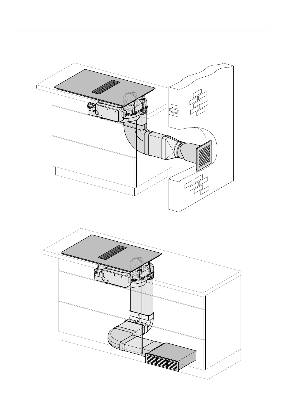
Installation
*INSTALLATION*
79
Installation examples
Extraction mode
Guided recirculation mode
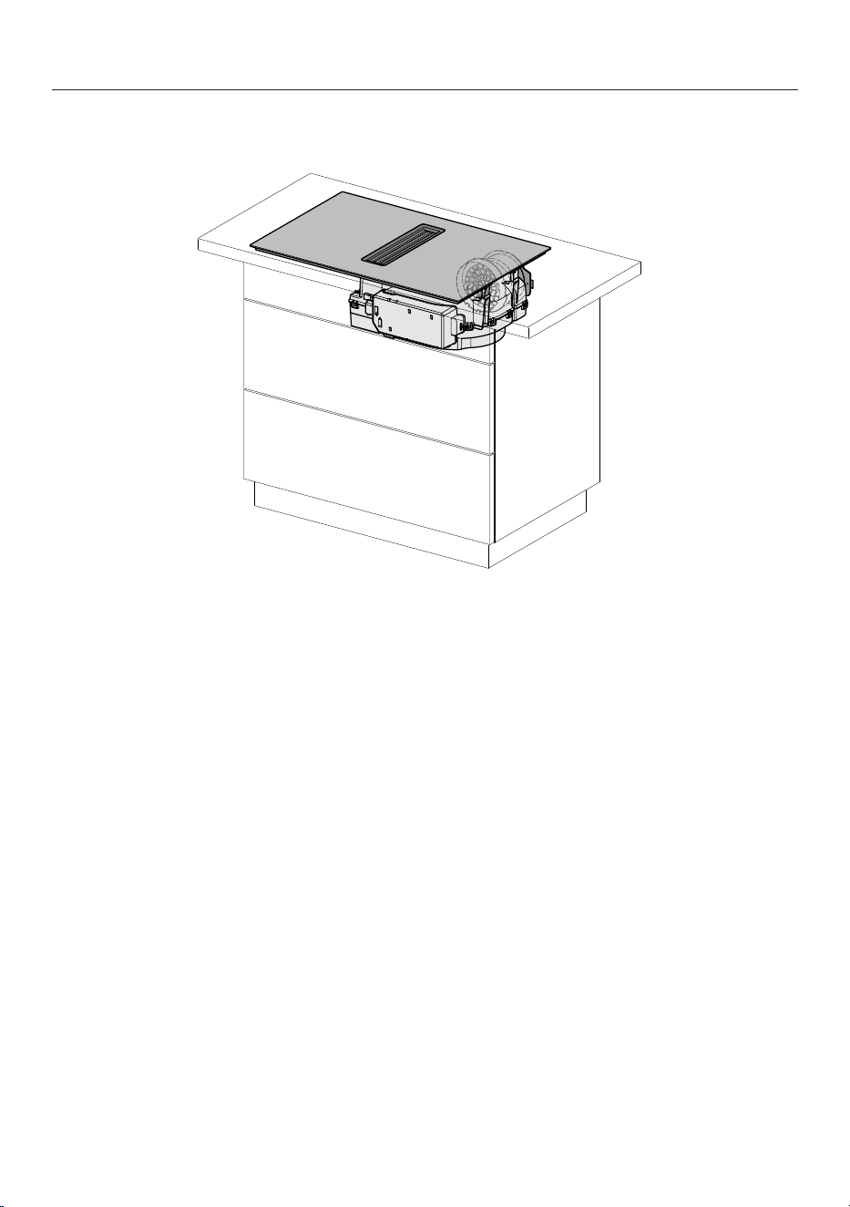
Installation
*INSTALLATION*
80
Plug&Play mode
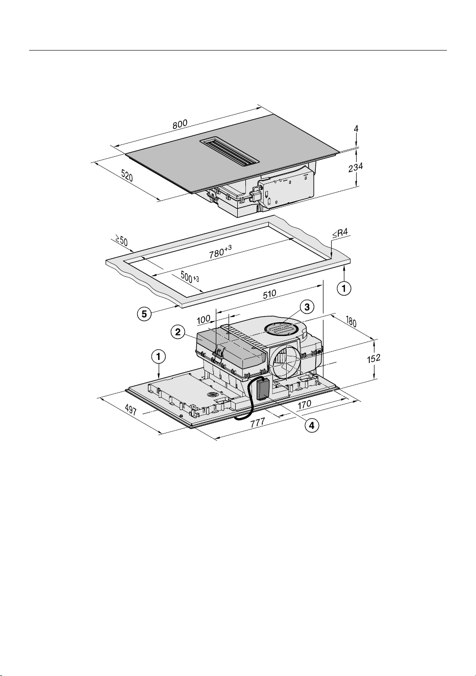
Installation
*INSTALLATION*
81
Building-in dimensions for surface-mounted installation
KMDA 7876 FL-A, KMDA 7876 FL-U
All dimensions are given in mm.
a
Front
b
Removable drip tray
c
Cleaning flap
d
Mains connection box with mains connection cable
Mains connection cable L=2000mm
e
Worktop thickness
Extraction and guided recirculation mode: ≥10mm
Plug&Play mode: ≥10mm–≤40mm
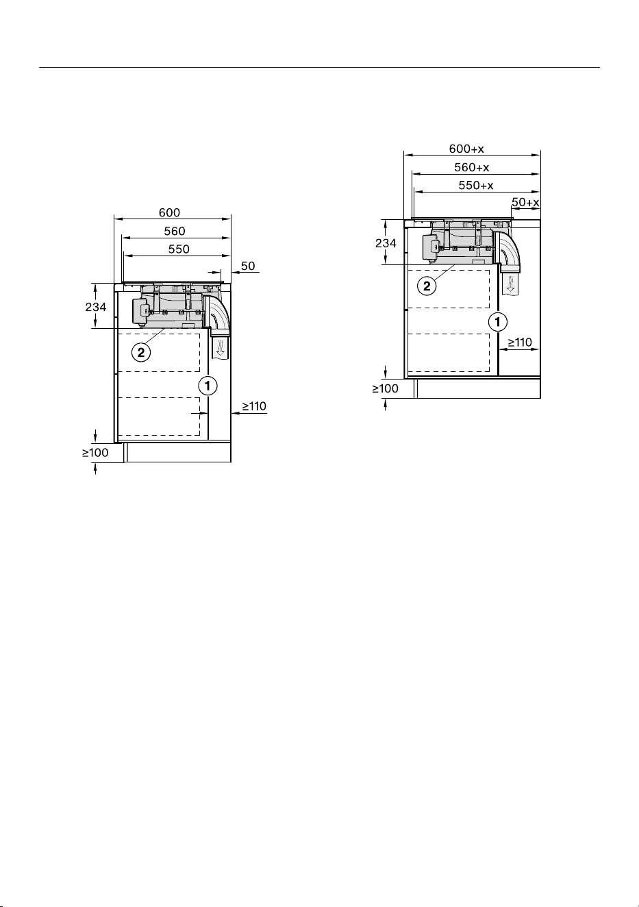
Installation
*INSTALLATION*
82
Extraction and guided recirculation
mode with surface-mounted installa-
tion
Worktop depth 600mm
KMDA 7876 FL-A, KMDA 7876 FL-U
a
For maintenance work it must be
possible to remove the rear cabinet
wall.
The cabinet wall and an adjoining
room wall or a piece of furniture
must be at least 110mm apart to en-
sure sufficient room for the ducting.
b
The removable drip tray and the
cleaning flap must be accessible
after installation.
Worktop depth greater than 600mm
KMDA 7876 FL-A, KMDA 7876 FL-U
a
For maintenance work it must be
possible to remove the rear cabinet
wall.
The cabinet wall and an adjoining
room wall or a piece of furniture
must be at least 110mm apart to en-
sure sufficient room for the ducting.
b
The removable drip tray and the
cleaning flap must be accessible
after installation.
x Dimension of which the worktop is
deeper than 600mm.
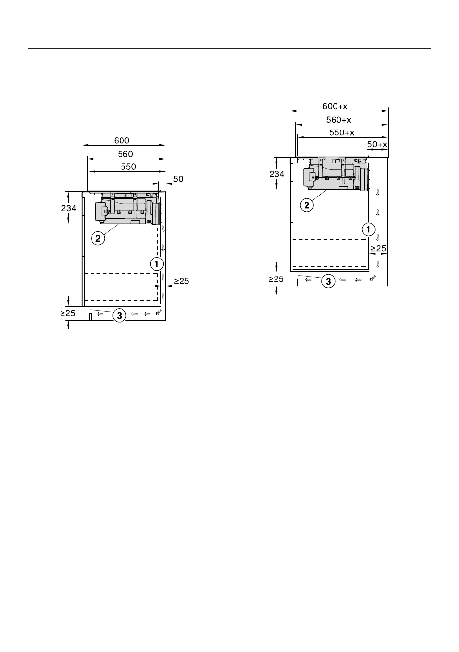
Installation
*INSTALLATION*
83
Plug&Play with surface-mounted in-
stallation
Worktop depth 600mm
KMDA 7876 FL-U
a
The housing unit wall and an adjoin-
ing room wall or a piece of furniture
must be at least 25mm apart to en-
sure sufficient room for the exhaust
air ducting.
b
The removable drip tray and the
cleaning flap must be accessible
after installation.
c
The cross-section of the ventilation
opening must be at least 425cm².
Worktop depth greater than 600mm
KMDA 7876 FL-U
a
The housing unit wall and an adjoin-
ing room wall or a piece of furniture
must be at least 25mm apart to en-
sure sufficient room for the exhaust
air ducting.
If the housing unit rear wall is
>555mm away from the front of the
worktop, the Plug&Play adapter
must be combined with an expan-
sion set from Miele.
b
The removable drip tray and the
cleaning flap must be accessible
after installation.
c
The cross-section of the ventilation
opening must be at least 425cm².
x Dimension of which the worktop is
deeper than 600mm.
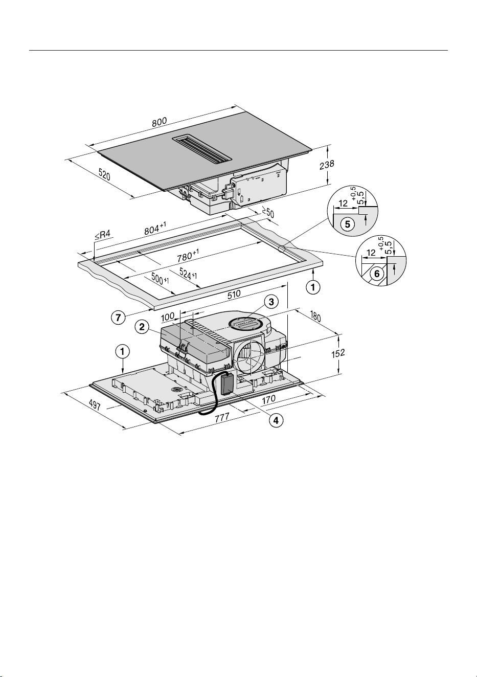
Installation
*INSTALLATION*
84
Installation dimensions for flush-fit installation
KMDA 7876 FL-A, KMDA 7876 FL-U
All dimensions are given in mm.
a
Front
b
Removable drip tray
c
Cleaning flap
d
Mains connection box with mains connection cable
Mains connection cable L=2000mm
e
Stepped cut-out, natural stone worktop
f
Wooden batten 12mm (not supplied)
g
Worktop thickness
Extraction and guided recirculation mode: ≥10mm
Plug&Play mode: ≥10mm–≤40mm
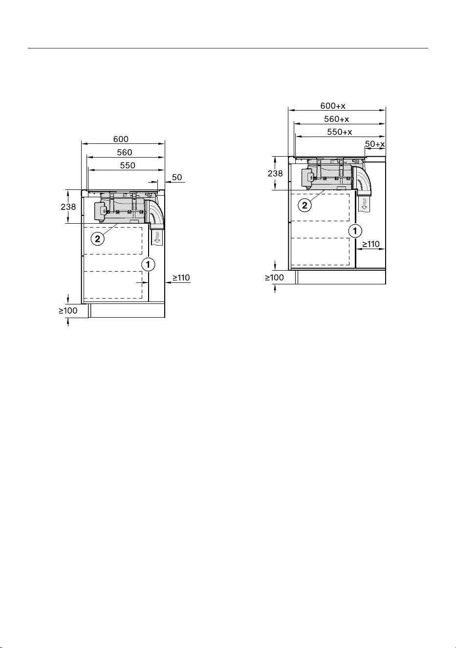
Installation
*INSTALLATION*
85
Extraction and guided recirculation
mode with flush-fit installation
Worktop depth 600mm
KMDA 7876 FL-A, KMDA 7876 FL-U
a
For maintenance work it must be
possible to remove the rear cabinet
wall.
The cabinet wall and an adjoining
room wall or a piece of furniture
must be at least 110mm apart to en-
sure sufficient room for the ducting.
b
The removable drip tray and the
cleaning flap must be accessible
after installation.
Worktop depth greater than 600mm
KMDA 7876 FL-A, KMDA 7876 FL-U
a
For maintenance work it must be
possible to remove the rear cabinet
wall.
The cabinet wall and an adjoining
room wall or a piece of furniture
must be at least 110mm apart to en-
sure sufficient room for the ducting.
b
The removable drip tray and the
cleaning flap must be accessible
after installation.
x Dimension of which the worktop is
deeper than 600mm.
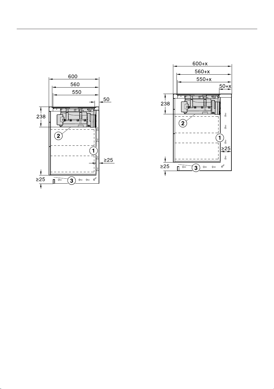
Installation
*INSTALLATION*
86
Plug&Play with flush-fit installation
Worktop depth 600mm
KMDA 7876 FL-U
a
The housing unit wall and an adjoin-
ing room wall or a piece of furniture
must be at least 25mm apart to en-
sure sufficient room for the exhaust
air ducting.
b
The removable drip tray and the
cleaning flap must be accessible
after installation.
c
The cross-section of the ventilation
opening must be at least 425cm².
Worktop depth greater than 600mm
KMDA 7876 FL-U
a
The housing unit wall and an adjoin-
ing room wall or a piece of furniture
must be at least 25mm apart to en-
sure sufficient room for the exhaust
air ducting.
If the housing unit rear wall is
>555mm away from the front of the
worktop, the Plug&Play adapter
must be combined with an expan-
sion set from Miele.
b
The removable drip tray and the
cleaning flap must be accessible
after installation.
c
The cross-section of the ventilation
opening must be at least 425cm².
x Dimension of which the worktop is
deeper than 600mm.
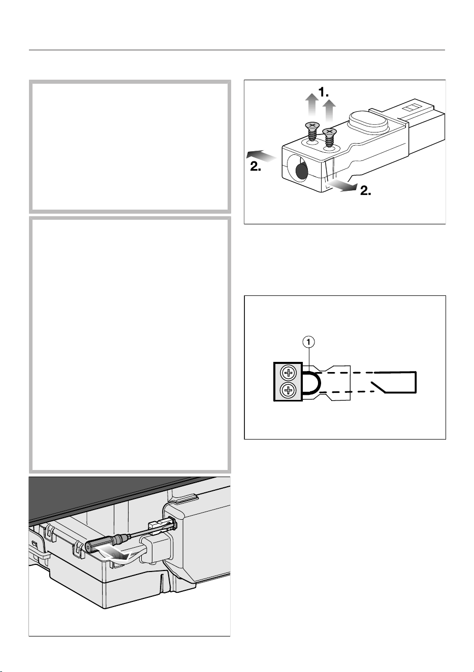
Installation
*INSTALLATION*
87
Connection to window contact
The window contact connection
is live.
Danger of electric shock.
Disconnect the hob from the mains
electricity supply before connecting
the switching system.
The connection cable for the switch-
ing system must only be connected
by a suitably qualified electrician.
The connection cable for the switch-
ing system must comply with type
H03VV-F 2x0.75mm
2
and must not
exceed 2.0m in length.
The switching system must be
equipped with a potential-free con-
tact suitable for 230V, 1A. The va-
pour extraction is switched off when
the switch is open.
Only use DIBt-approved and tested
radio switching systems (e.g. window
contact switches, pressure switches)
and have them approved by author-
ised specialists (e.g. building regula-
tions inspector).
You will need the appropriate external
switching system documents to
safely connect and operate the
switch.
Loosen the latch and pull the plug out.
Loosen the strain relief screws and
unlock the casing on both sides.
Open the casing.
Remove the stopper.
Exchange the bridge for the con-
nection cable of the switching sys-
tem.
Close the casing.
Tighten the strain relief screw.
Reinsert the plug.

Installation
*INSTALLATION*
88
Installing a surface-mounted hob with extraction and guided recir-
culation mode
Create the worktop cut-out. Remember to maintain the minimum safety dis-
tances (see “Installation – Safety distances”).
Seal any cut surfaces on wooden worktops with a special varnish, silicone seal-
ant or resin to prevent the wood from swelling as a result of moisture ingress. The
sealant must be heat-resistant.
Make sure that the sealant does not come into contact with the top of the work-
top.
Attach the sealing strip provided underneath the edge of the hob. Do not apply
the sealing strip under tension.
Feed the mains connection cable for the hob down through the worktop cut-out.
Place the hob centrally in the cut-out. When doing this, make sure that the seal
of the appliance sits flush with the worktop on all sides. This is important to en-
sure an effective seal all round.
If the seal does not sit flush with the worktop in the corners, the corner radius
(≤R4) can be carefully cut to fit using a jigsaw.
Connect the hob to the mains electricity supply.
Check that the hob works.
Installation
*INSTALLATION*
89
Installing a surface-mounted hob with Plug&Play
Create the worktop cut-out. Remember to maintain the minimum safety dis-
tances (see “Installation – Safety distances”).
Cut the top of the drilling template to the thickness of your worktop. Depending
on the installation depth, place the correct drilling template on top of the housing
unit rear wall. Use the drilling template to create a cut-out for the Plug&Play ad-
apter.
Installation depth Drilling template number Adapter position
23,8cm
1
2 2
24,8cm
2
3a 3
1
The template is supplied with the appliance.
2
The templates can be found on the Miele homepage.
If you do not have a drilling template, see “Installation – Rear wall cut-out
without drilling template”.
Seal any cut surfaces on wooden worktops with a special varnish, silicone seal-
ant or resin to prevent the wood from swelling as a result of moisture ingress. The
sealant must be heat-resistant.
Make sure that the sealant does not come into contact with the top of the work-
top.
Attach the sealing strip provided underneath the edge of the hob. Do not apply
the sealing strip under tension.
The Plug&Play adapter may break off.
When placing the hob on the worktop, make sure that it is not placed on top of
the Plug&Play adapter.
Connect the Plug&Play adapter to the hob and set the adapter position.
Feed the mains connection cable for the hob down through the worktop cut-out.
Remove the protective foil from the adhesive tape at the end of the Plug&Play
adapter.
Place the hob centrally in the cut-out. When doing this, make sure that the seal
of the appliance sits flush with the worktop on all sides. This is important to en-
sure an effective seal all round.
If the seal does not sit flush with the worktop in the corners, the corner radius
(≤R4) can be carefully cut to fit using a jigsaw.
Align the Plug&Play adapter with the predrilled hole. Press the adapter onto the
rear wall until it sticks in place.
Connect the hob to the mains electricity supply.
Check that the hob works.

Installation
*INSTALLATION*
90
Installing a flush-fit hob with extraction and guided recirculation
mode
Create the worktop cut-out. Remember to maintain the minimum safety dis-
tances (see “Installation – Safety distances”).
Solid wood, tiled and glass worktops:
Fix a wooden frame 5,5mm below the top edge of the worktop (see “Installation
– Building-in dimensions for flush-fit installation”).
Attach the sealing strip provided underneath the edge of the hob. Do not apply
the sealing strip under tension.
Feed the mains connection cable for the hob down through the worktop cut-out.
Centre the hob in the cut-out.
The gap between the ceramic glass surface and the worktop must be at least
2mm wide. This is required so that the hob can be sealed.
Connect the hob to the mains electricity supply.
Check that the hob works.
Seal the gap between the hob and worktop with a silicone sealant that is heat-
resistant to at least 160°C.
Installation
*INSTALLATION*
91
Installing a flush-fit hob with Plug&Play
Create the worktop cut-out. Remember to maintain the minimum safety dis-
tances (see “Installation – Safety distances”).
Cut the top of the drilling template to the thickness of your worktop. Depending
on the installation depth, place the correct drilling template on top of the housing
unit rear wall. Use the drilling template to create a cut-out for the Plug&Play ad-
apter.
Installation depth Drilling template number Adapter position
23,8cm
1
1 1
24,8cm
2
3b 3
1
The template is supplied with the appliance.
2
The templates can be found on the Miele homepage.
If you do not have a drilling template, see “Installation – Rear wall cut-out
without drilling template”.
Solid wood, tiled and glass worktops:
Fix a wooden frame 5,5mm below the top edge of the worktop (see “Installation
– Building-in dimensions for flush-fit installation”).
Attach the sealing strip provided underneath the edge of the hob. Do not apply
the sealing strip under tension.
The Plug&Play adapter may break off.
When placing the hob on the worktop, make sure that it is not placed on top of
the Plug&Play adapter.
Connect the Plug&Play adapter to the hob and set the adapter position.
Feed the mains connection cable for the hob down through the worktop cut-out.
Plug&Play mode: remove the protective foil from the adhesive tape at the end of
the Plug&Play adapter.
Centre the hob in the cut-out.
The gap between the ceramic glass surface and the worktop must be at least
2mm wide. This is required so that the hob can be sealed.
Plug&Play mode: align the Plug&Play adapter with the predrilled hole. Press the
adapter onto the rear wall until it sticks in place.
Connect the hob to the mains electricity supply.
Check that the hob works.
Seal the gap between the hob and worktop with a silicone sealant that is heat-
resistant to at least 160°C.
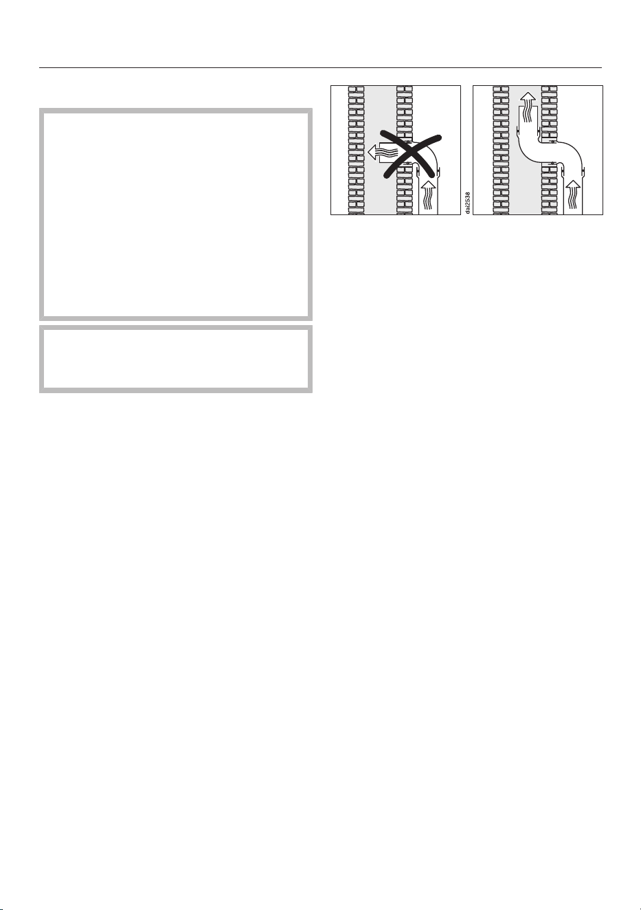
Installation
*INSTALLATION*
92
Installing exhaust ducting
If the vapour extraction is used at
the same time as a heating appliance
that relies on oxygen from the same
room, there is a risk of toxic fumes.
It is essential that the “Warnings and
safety notes” are observed.
The vapour extraction should be in-
stalled according to local and na-
tional building regulations. Seek ap-
proval from the building regulations
inspector where necessary.
Remember that any constriction of
the air flow will reduce air throughput
and increase operating noise.
The vapour extraction has an exhaust
duct of Ø 150mm.
Only use smooth pipes or flexible ex-
haust hoses made from non-flam-
mable materials for exhaust ducting.
To achieve the most efficient air
throughput with the lowest noise
levels, please note the following:
- The cross-section of the exhaust
ducting must not be smaller than the
cross-section of the exhaust connec-
tion (see the appliance dimensions).
- The ducting should be as short and
straight as possible.
- Only use wide radius bends.
- The exhaust ducting must not be
kinked or compressed.
- Ensure that all connections are strong
and airtight.
If the exhaust air is to be ducted into
a flue, the ducting must be directed in
the flow direction of the flue.
If ducting is to be laid horizontally it
must be laid with a downwards slop-
ing gradient. This is to ensure that
condensate cannot drain back into
the fan.
If the ducting is to run through cool
rooms, ceiling space, etc., there may
be great variations in temperature
between the different areas. The
problem of condensation will need to
be addressed. The ducting will need
to be suitably insulated.
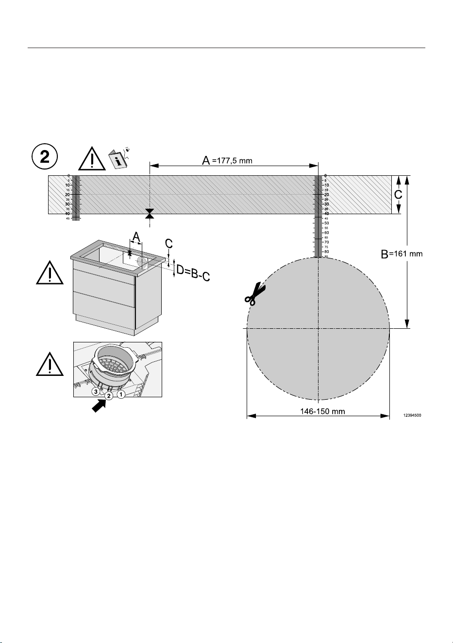
Installation
*INSTALLATION*
93
Rear wall cut-out without drilling template
Creating the rear wall cut-out with surface-mounted installation and an installa-
tion depth of 23,8cm
Ideally, the drilling template supplied with the appliance should be used. The fol-
lowing instructions should only be used if the drilling template is not available.
View of the drilling template side 2. Not to scale.
Measure the thickness of your worktop (C).
Locate the centre of the long axis of the cut-out.
Mark the point that is 177.5mm (A) to the right of the midpoint.
Mark the point (D) that is (B [161mm] – C [thickness of the worktop]) below the
right end of distance A.
Saw a hole with a diameter of 146–150mm around this point.
Plug&Play mode only: engage the Plug&Play adapter in position2.

Installation
*INSTALLATION*
94
Creating the rear wall cut-out with flush-fit installation and an installation depth
of 23,8cm
Ideally, the drilling template supplied with the appliance should be used. The fol-
lowing instructions should only be used if the drilling template is not available.
View of the drilling template side 1. Not to scale.
Measure the thickness of your worktop (C).
Locate the centre of the long axis of the cut-out.
Mark the point that is 183mm (A) to the right of the midpoint.
Mark the point (D) that is (B [159.5mm] – C [thickness of the worktop]) below
the right end of distance A.
Saw a hole with a diameter of 146–150mm around this point.
Plug&Play mode only: engage the Plug&Play adapter in position1.
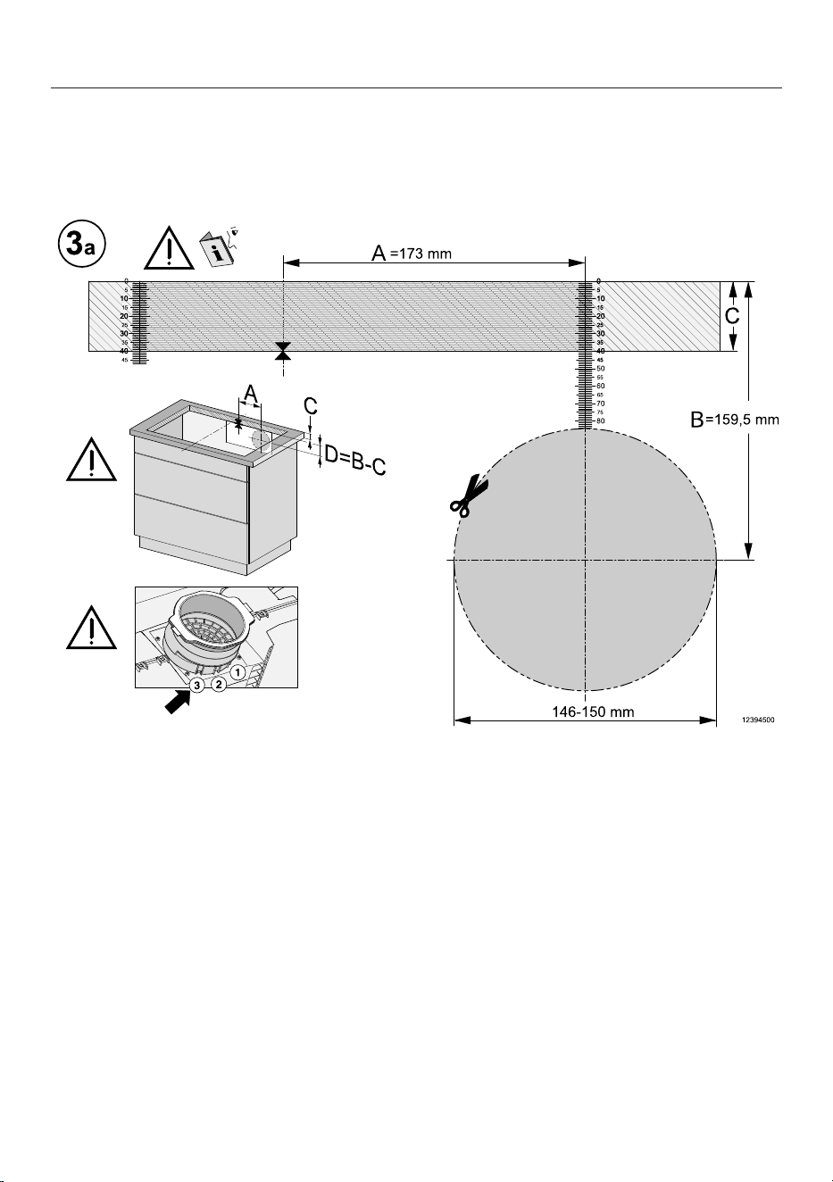
Installation
*INSTALLATION*
95
Creating the rear wall cut-out with surface-mounted installation and an installa-
tion depth of 24,8cm
Ideally, the drilling template supplied with the appliance should be used. The fol-
lowing instructions should only be used if the drilling template is not available.
View of the drilling template side 3a. Not to scale.
Measure the thickness of your worktop (C).
Locate the centre of the long axis of the cut-out.
Mark the point that is 173mm (A) to the right of the midpoint.
Mark the point (D) that is (B [159.5mm] – C [thickness of the worktop]) below
the right end of distance A.
Saw a hole with a diameter of 146–150mm around this point.
Plug&Play mode only: engage the Plug&Play adapter in position3.
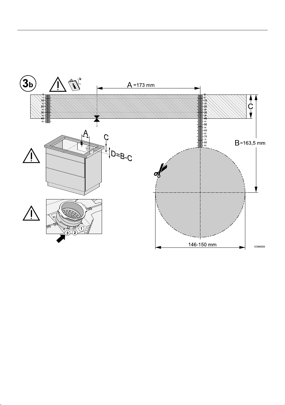
Installation
*INSTALLATION*
96
Creating the rear wall cut-out with flush-fit installation and an installation depth
of 24,8cm
Ideally, the drilling template supplied with the appliance should be used. The fol-
lowing instructions should only be used if the drilling template is not available.
View of the drilling template side 3b. Not to scale.
Measure the thickness of your worktop (C).
Locate the centre of the long axis of the cut-out.
Mark the point that is 173mm (A) to the right of the midpoint.
Mark the point (D) that is (B [163.5mm] – C [thickness of the worktop]) below
the right end of distance A.
Saw a hole with a diameter of 146–150mm around this point.
Plug&Play mode only: engage the Plug&Play adapter in position3.

Installation
*INSTALLATION*
97
Electrical connection
Risk of damage from incorrect
connection.
Unauthorised installation, mainten-
ance and repairs can cause consider-
able danger for the user.
Miele cannot be held liable for dam-
age or injury caused by unauthorised
installation, maintenance or repair
work, or by an inadequate or faulty
on-site earthing system (e.g. electric
shock).
This hob must be connected to the
electrical supply by a qualified elec-
trician.
The electrician must be familiar with
and comply with the national regula-
tions and any additional regulations
of the local electricity provider (e.g.
BS 7671 in the UK).
After installation, ensure that all elec-
trical components are shielded and
cannot be accessed by users.
Total power rating
See data plate
Connection data
The connection data is quoted on the
data plate. Please ensure these match
the household mains supply.
Please see wiring diagrams for connec-
tion. (N.B. This appliance is supplied
single phase only in the UK / AUS / NZ).
Residual current device
For extra safety, it is advisable to protect
the appliance with a suitable residual
current device (RCD) with a trip range
of 30 mA.
WARNING
THIS APPLIANCE MUST BE
EARTHED
Disconnecting devices
It must be possible to disconnect the
hob from the mains at all poles using
disconnecting devices. A contact dis-
tance of at least 3mm must be ob-
served in the switched-off state. The
disconnecting devices are overcurrent
protection devices and residual current
protection devices.
Installation
*INSTALLATION*
98
Disconnecting from the mains
Risk of electric shock.
There is a risk of electric shock if the
appliance is connected to the mains
supply during repair or service work.
After disconnection, ensure the appli-
ance cannot be switched back on by
mistake.
To disconnect the appliance from the
mains power supply, do one of the fol-
lowing depending on installation:
Safety fuses
Completely remove fuses.
Automatic circuit breakers
Press the (red) test button until the
middle (black) button springs out.
Built-in circuit breakers
Circuit breakers at least type B or C:
Switch the lever from 1 (on) to 0 (off).
Residual current device (RCD)
Switch the main switch from 1 (on) to
0 (off) or press the test button.
Mains connection cable
The hob must be connected to the elec-
trical supply with a special connection
cable, type H05VV-F (PVC insulated)
with a suitable diameter.
Please see wiring diagrams for connec-
tion. (N.B. This appliance is supplied
single phase only in the UK / AUS / NZ).
See the data plate on the hob for the
correct voltage and rated load.
Replacing the mains connection cable
Risk of electric shock.
Incorrect connection to the power
supply may result in an electric
shock.
The mains cable must only be re-
placed by a qualified electrician.
When replacing the mains cable only
use cable type H05VV-F (PVC insu-
lated) with a suitable cross section. A
suitable connection cable is available to
order from Miele.
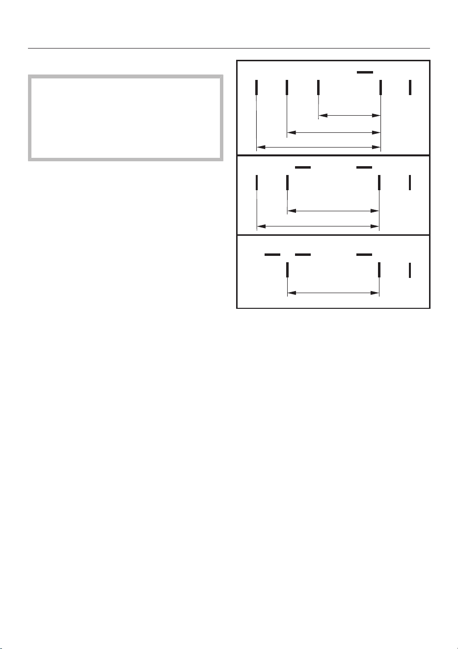
Installation
*INSTALLATION*
99
Wiring diagram
Some connection methods are not
permitted in all installation locations.
Ensure compliance with national reg-
ulations and any additional regula-
tions issued by the local electricity
provider.
L1
200-240 V~
200-240 V~
200-240 V~
ab
cde
-
L2 L3 N
-
L2
b
L1
a cd
N
e
(L3)
200-240 V~
200-240 V~
a
L1
bcd
N
e
-
(L2)
200-240 V~
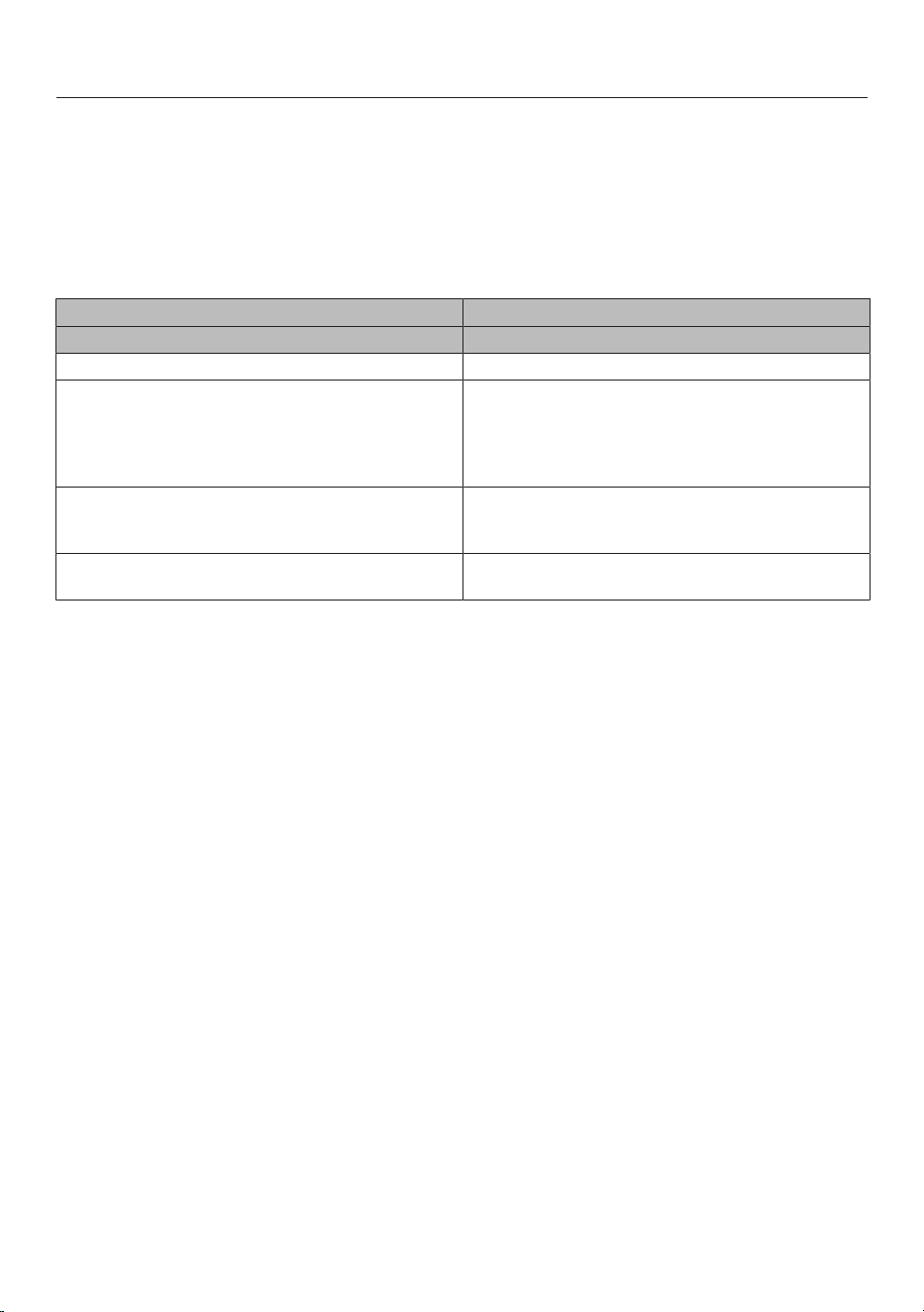
Installation
*INSTALLATION*
100
Product data sheets
The following data sheets apply to the models described in this operating instruc-
tion manual.
Information for domestic electric hobs
In acc. with regulation (EU) No. 66/2014
MIELE
Model name/identifier KMDA 7676 FL-A, KMDA 7676 FL-U
Number of cooking zones and/or areas 4
For circular cooking zones: diameter of useful sur-
face area/cooking zone
For non-circular cooking zones or areas: length and
width of useful surface area per electric cooking
zone or area
1. = 230x460 mm
2. = 230x460 mm
3. =
4. =
Energy consumption per cooking zone or area cal-
culated per kg (EC
electric cooking
)
1. = 180,1 Wh/kg
2. = 180,7 Wh/kg
Energy consumption for the hob calculated per kg
(EC
electric hob
)
180,4 Wh/kg
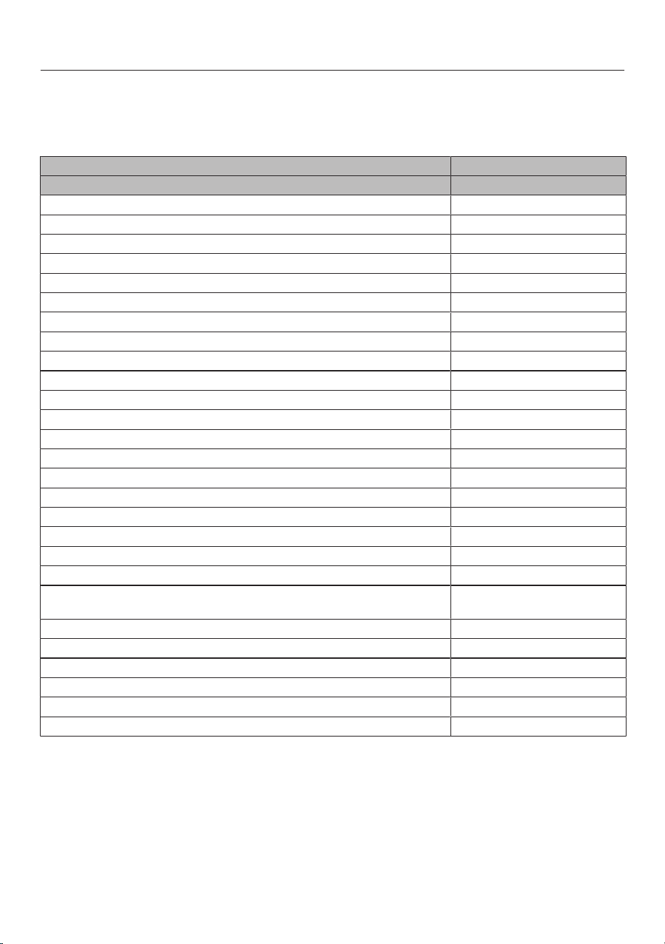
Installation
*INSTALLATION*
101
Data sheet for household cooker hoods
In acc. with delegated regulation (EU) No. 65/2014 and regulation (EU) No.
66/2014
MIELE
Model name/identifier KMDA 7676 FL-A
Annual Energy Consumption (AEC
hood
) kWh/year
Energy efficiency class A+
Energy efficiency index (EEI
hood
) 38,1
Fluid Dynamic Efficiency (FDE
hood
) 35,0
Fluid Dynamic Efficiency class
A (most efficient) to G (least efficient) A
Lighting Efficiency (LE
hood
) lx/W
Lighting Efficiency class
A (most efficient) to G (least efficient) -
Grease Filtering Efficiency 95,1%
Grease Filtering Efficiency class
A (most efficient) to G (least efficient) A
Airflow at best efficiency point 318,3 m
3
/h
Air flow (min. speed) 196 m
3
/h
Air flow (max. speed) 530 m
3
/h
Air flow (intensive or boost setting) 605 m
3
/h
Max. air flow (Q
max
) 605,0 m
3
/h
Air pressure at best efficiency point 502 Pa
Airborne acoustical A-weighted sound power emissions (min. speed) 41 dB
Airborne acoustical A-weighted sound power emissions (max. speed) 65 dB
Airborne acoustical A-weighted sound power emissions (intensive or
boost setting)
68 dB
Electrical power input at best efficiency point 126,9 W
Power consumption in off mode (P
o
) W
Power consumption in standby mode (P
s
) W
Nominal power of lighting system 0,0 W
Average illumination of the lighting system on the cooking surface 0 Ix
Time increase factor 0,7
Installation
*INSTALLATION*
102
UK Conformity declaration
Miele hereby declares that this ceramic induction hob complies with UK Radio
Equipment Regulations 2017, as amended.
The complete text of the UK declaration of conformity is available from one of the
following internet addresses:
- Products, Download from www.miele.co.uk
- For service, information, operating instructions etc: go to https://miele.co.uk/
manuals and enter the name of the product or the serial number
Frequency band of the WiFi module 2.4000GHz – 2.4835GHz
Maximum transmitting power of the
WiFi module
<100mW
ThisStatement of Compliance confirms this Miele product fully complies with the
Product Security and Telecommunications Infrastructure (Security Requirements
for Relevant Connectable Products) Regulations 2023.
1)
Household Appliance –
2)
Manufactured by: Miele & Cie KG,
Carl Miele Street 29, 33332 Gutersloh Germany
Imported by and contact point: Miele Company Ltd, Fairacres, Marcham Road,
Abingdon, Oxon, OX14 ITW Great Britain
The defined support period at the time of first supply is 10 years
3)
To report vulnerabilities and cybersecurity issues please contact: [email protected]
4)
5)
Signature
Name: Paul Wright
Company Position: Head of Technical Management
Date of signature: 19th March 2024
Place of signature:
Abingdon, Oxfordshire
Induction hobs ICE07-02W

United Kingdom
Miele Co. Ltd., Fairacres, Marcham Road, Abingdon, Oxon, OX14 1TW
Tel: 0330 160 6600, Internet: www.miele.co.uk, E-mail: [email protected]
Australia
Miele Australia Pty. Ltd.
ACN 005 635 398
ABN 96 005 635 398
Level 4, 141 Camberwell Road
Hawthorn East, VIC 3123
Tel: 1300 464 353
E-mail: [email protected]
Internet: www.miele.com.au
Miele Electrical Appliances Co., Ltd.
1-3 Floor, No. 82 Shi Men Yi Road
Jing' an District
200040 Shanghai, PRC
Tel: +86 21 6157 3500
Fax: +86 21 6157 3511
E-mail: [email protected]
Internet: www.miele.cn
China Mainland
Miele (Hong Kong) Ltd.
41/F - 4101, Manhattan Place
23 Wang Tai Road
Kowloon Bay, Hong Kong
Tel: (852) 2610 1025
Fax: (852) 3579 1404
E-mail:
Website: www.miele.hk
Hong Kong, China
Miele India Pvt. Ltd.
1st Floor, Copia Corporate Suites,
Commercial Plot 9, Mathura Road,
Jasola, New Delhi - 110025
E-mail: customercare@miele.in
Website: www.miele.in
India
Miele Ireland Ltd.
2024 Bianconi Avenue
Citywest Business Campus
Dublin 24
Tel: (01) 461 07 10
Fax: (01) 461 07 97
E-mail: [email protected]
Internet: www.miele.ie
Ireland
Malaysia
Miele Sdn Bhd
Suite 12-2, Level 12
Menara Sapura Kencana
Petroleum
Solaris Dutamas No. 1
Jalan Dutamas 1
50480 Kuala Lumpur, Malaysia
Phone: +603-6209-0288
Fax: +603-6205-3768
Miele New Zealand Limited
IRD 98 463 631
8 College Hill
Freemans Bay, Auckland 1011
Tel: 0800 464 353
Internet: www.miele.co.nz
New Zealand
Miele Pte. Ltd.
29 Media Circle
#11-04 ALICE@Mediapolis
Singapore 138565
Tel: +65 6735 1191
Fax: +65 6735 1161
E-mail: [email protected]
Internet: www.miele.sg
Singapore
Miele (Pty) Ltd.
63 Peter Place, Bryanston 2194
Tel: (011) 875 9000
Fax: (011) 875 9035
E-mail: [email protected]
Internet: www.miele.co.za
South Africa
Miele Appliances Ltd.
Showroom 1, Eiffel 1 Building
P.O. Box 114782 - Dubai
Tel. +971 4 3044 999
Fax. +971 4 3418 852
800-MIELE (64353)
E-mail: [email protected]
Website: www.miele.ae
United Arab Emirates
Manufacturer: Miele & Cie. KG, Carl-Miele-Straße 29, 33332 Gütersloh, Germany
Thailand
Miele Appliances Ltd.
BHIRAJ TOWER at EmQuartier
43rd Floor Unit 4301-4303
689 Sukhumvit Road
North Klongton Sub-District
Vadhana District
Bangkok 10110, Thailand
Sheikh Zayed Road, Umm Al Sheif
E-mail: customercare@miele.co.nz
P.O. Box 69434, Bryanston 2021

M.-Nr. 12 645 301 / 00en-GB
KMDA7676FL‑A, KMDA7676FL‑U