
Operating Instructions / Owner’s Manual
<Complete Guide>
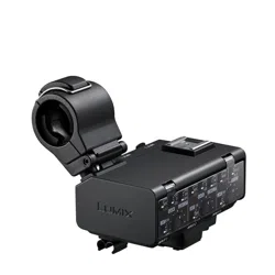
XLR Microphone Adaptor
Model No. DMW-XLR2
Please read these instructions carefully before using this product.
DVQP3126ZA
F0624KN0
until
2024/07/01

2
About Operating Instructions
This document, “Operating Instructions / Owner’s Manual <Complete
Guide>”, includes detailed explanations of the functions and operations of
the unit.
Symbols Used in This Document
Notification classification symbols
In this document, notifications are classified and described using the following
symbols:
: To confirm prior to using the function
: Notifications and supplementary items regarding specifications
• Images and illustrations used in this document are for explaining the functions.

3
Contents
About Operating Instructions 2
Introduction 4
Precautions..................................................................................5
Standard Accessories..................................................................7
Names of Parts ............................................................................8
Getting Started 10
Attaching the Microphone Holder ..............................................11
Attaching to the Camera ............................................................14
Connecting a Microphone..........................................................16
Connecting External Audio Devices, etc....................................22
Using the XLR Microphone Adaptor 24
Setting the Recording Channels ................................................25
Setting Input Gain ......................................................................28
Setting the Recording Level.......................................................29
Decrease Noise Caused by Wind or Handling ..........................31
Materials 32
Cautions for Use ........................................................................33
Specifications.............................................................................36


Introduction – Precautions
5
Precautions
This unit is an XLR microphone adaptor for Panasonic digital cameras.
Commercially available XLR microphones and stereo microphones
(compatible with stereo mini plugs) can be fitted.
Use in combination with a digital camera to enable high-quality audio
recordings, high-resolution audio recordings, and 4-channel audio
recordings.
Furthermore, by using in combination with a digital camera that supports
float recording, it is also possible to make 32-bit float recordings capable of
high-quality audio recordings without having to make settings for the
recording level.
Compatible models (As of June 2024)
Compatible models: DC-GH7, DC-GH6
*
* Use with the firmware on the Digital Camera updated to the most recent version.
DC-GH6 does not support float recording or 4-channel audio recording with just a
microphone connected to this unit.
• For the latest information on the firmware or to download/update the firmware, visit
the following support site:
https://panasonic.jp/support/global/cs/dsc/download/index.html
(English only)
• For the latest information on compatible devices, see the operating instructions,
catalogue or website of the digital camera.

Introduction – Precautions
6
Handling the unit
Do not subject the unit to strong vibration or impact. Those actions
may result in malfunctions and failure.
Sand and dirt may cause the unit to malfunction. When using the unit
in an environment such as a beach, take steps to protect it from sand
and dirt.
When using the unit on rainy days or on a beach, take care to keep
the unit dry.
This unit is neither dust-proof nor splash-resistant. If by any chance
water droplets, etc. are splashed on the unit, wipe them off with a dry
cloth. If the unit fails to function correctly, consult your dealer or
Panasonic.
Please also read the manual of your digital camera.
•
Please be advised that Panasonic is not liable for any damage directly or
indirectly caused by use or malfunction of this product.
• The external design and specifications of this product, as described in this
document, may differ from the actual product due to improvements made.
Introduction – Standard Accessories
7
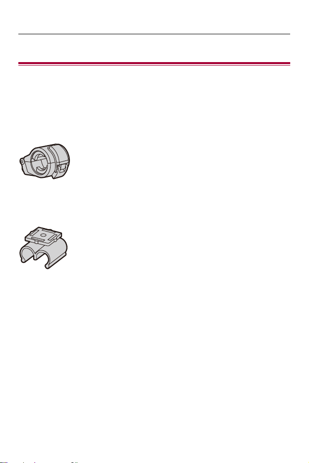
Standard Accessories
Check the supplied items. (Product numbers correct as of June 2024.)
Pouch
DVPY1024Z
Microphone holder
1AC1XLRMC8243Z
Cable holder
DVGE1055Z
• This is attached to the unit at the time of purchase.
• Consult the dealer or Panasonic if you lose the supplied accessories. (You can
purchase the accessories separately.)
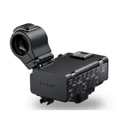
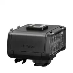
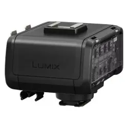
Introduction – Names of Parts
8
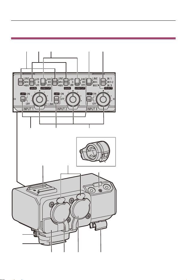
Names of Parts
(1) (2)
(6) (8)(7)
(3) (4) (5)
(1
3
)
(14)
(15)
(16) (19)(17) (18)
(9) (10)
(11)
(12)

Introduction – Names of Parts
9
(1) LINE/MIC/i48V switch (INPUT1/INPUT2)
(2) GAIN switch (INPUT1/INPUT2)
(3) LOW CUT switch (INPUT1/INPUT2)
(4) LINE/MIC/MIC switch (INPUT3)
(5) SELECT switch
(6) LMT switch (INPUT1/INPUT3)
(7) LMT/LINK switch (INPUT2)
(8) AUDIO LEVEL dial (INPUT1/INPUT2/INPUT3)
(9) Accessory shoe
(10) Release lever
(11) Microphone holder
(12) Buckle
(13) Microphone holder mounting section
(14) Lock lever
(15) Hot shoe mount
(16) Microphone terminal (INPUT3)
(17) XLR terminal (INPUT2)
(18) XLR terminal (INPUT1)
(19) Cable holder

Getting Started – Attaching the Microphone Holder
11
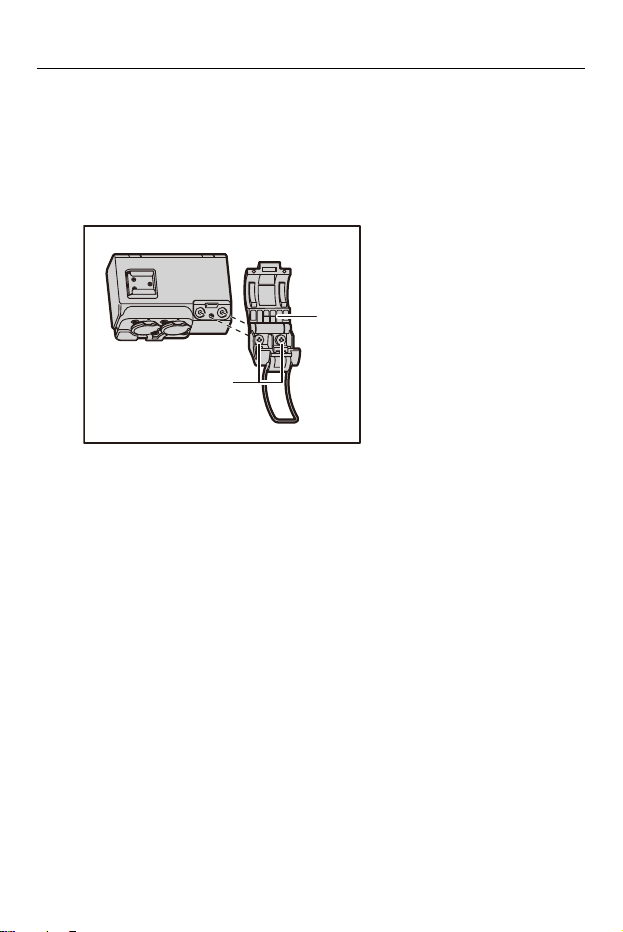
Attaching the Microphone Holder
Attach the supplied microphone holder to this unit.
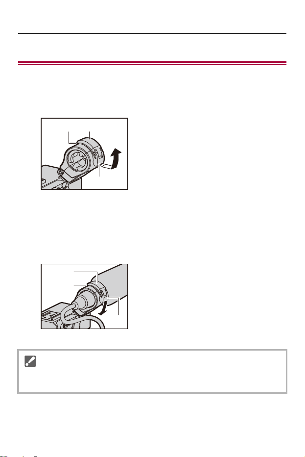
1
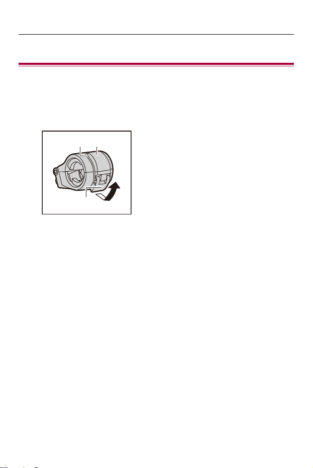
Open the microphone holder.
• Open buckle (1), and detach fitting (2) from hook (3).
(1)
(2) (3)
Getting Started – Attaching the Microphone Holder
12
2
Attach the microphone holder to the microphone holder
mounting section.
• Firmly screw in the screws of the microphone holder into the screw holes on
the microphone holder mounting section.
• Attach using a commercially-available screwdriver.
(A) Microphone holder
(B) Screws
(A)
(B)
Getting Started – Attaching the Microphone Holder
13
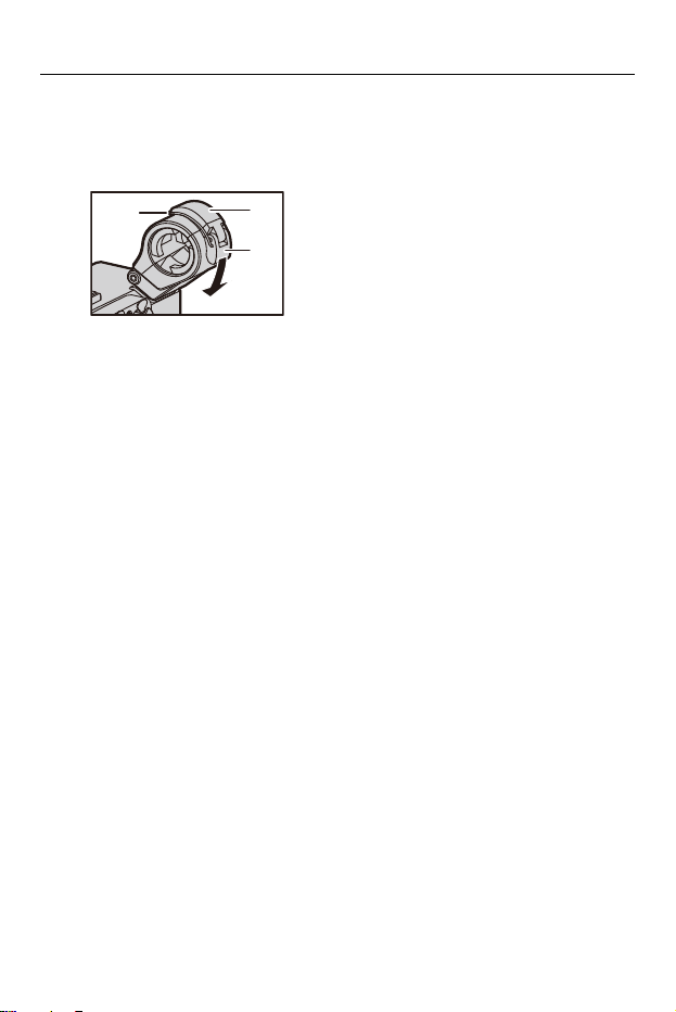
3
Close the microphone holder.
• Attach the fitting (1) to the hook (2) and close the buckle (3) in the direction
indicated by the arrow.
(1)
(2)
(3)
Getting Started – Attaching to the Camera
14
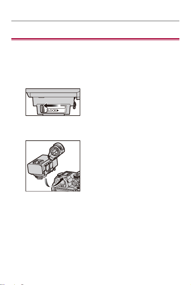
Attaching to the Camera
Confirm that the camera is off. Attaching or removing the XLR microphone
adaptor while the camera is on may result in malfunction.
1
Slide the lock lever in the direction opposite to that
indicated by the [LOCK 1] icon.
2
Slide the XLR microphone adaptor into the hot shoe
until it clicks securely into place.
Getting Started – Attaching to the Camera
15
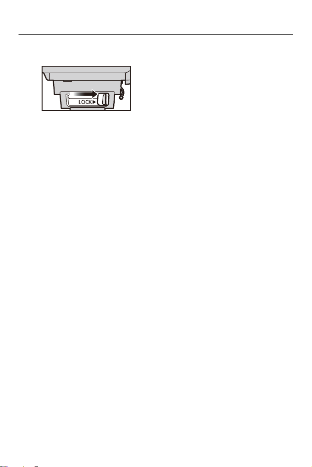
3
Slide the lock lever to the [LOCK 1] position.
• To remove the XLR microphone adaptor, slide the lock lever in the
direction opposite to the [LOCK 1] arrow and slide it from the hot shoe.
Getting Started – Connecting a Microphone
16
Connecting a Microphone
Attaching a Microphone
1
Open the microphone holder.
• Open buckle (1), and detach fitting (2) from hook (3).
2
Attach the external microphone to the microphone
holder, then close the buckle to secure the external
microphone.
• Attach the fitting (1) to the hook (2) and close the buckle (3) in the direction
indicated by the arrow.
• When recording while using a microphone, take care that the microphone does
not get in the shot.
(1)
(2) (3)
(1)
(2)
(3)
Getting Started – Connecting a Microphone
17
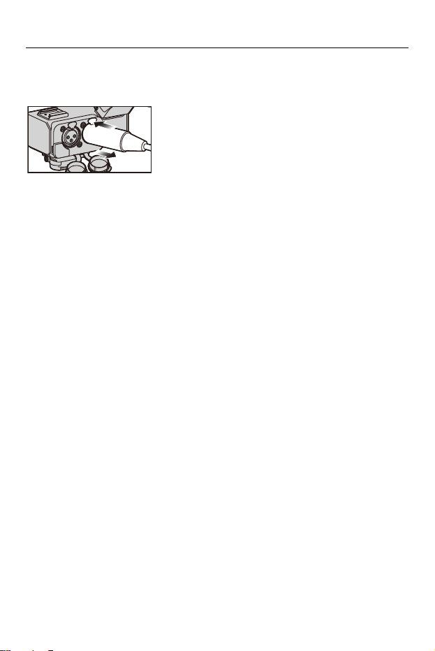
Connecting an XLR Microphone
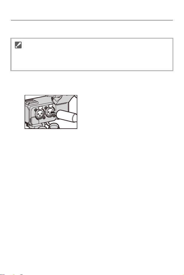
1
Insert the microphone cable plug into the XLR terminal
of the unit.
• To prevent unnecessary force being applied to the digital camera hot shoe, insert
the plug while holding the unit with your hand.
• If there is only one cable to be connected, connect it to terminal [INPUT1].
Getting Started – Connecting a Microphone
18
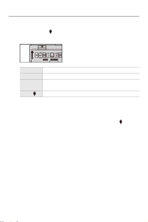
2
Set the LINE/MIC/i48V switch (INPUT1/INPUT2) to
match the connected device.
• When set to [i48V], connecting a device that does not support i48V power
supply may cause damage to the connected device. Check the device before
connecting.
• If noise from the unconnected terminal is bothering, set the LINE/MIC/i48V
switch to [LINE].
[LINE] External audio devices (such as mixers)
[MIC] Dynamic microphone or microphone with built-in battery
[i48V]
Microphone that supports i48V power supply (phantom
power supply)

Getting Started – Connecting a Microphone
19
3
Set the channels to record with the SELECT switch.
(Setting the Recording Channels: 25)
4
Set the input gain with the GAIN switch (INPUT1/
INPUT2). (Setting Input Gain: 28)
5
Set the recording level with the AUDIO LEVEL dial
(INPUT1/INPUT2/INPUT3). (Setting the Recording
Level: 29)
• Use a shielded XLR microphone cable with a XLR (3 pin) terminal.
• When using a stereo microphone that has 2 XLR (3 pin) plugs, connect the Lch to
the XLR terminal (INPUT1) and the Rch to the XLR terminal (INPUT2).
Getting Started – Connecting a Microphone
20
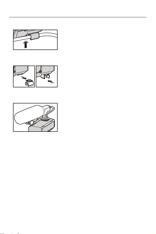
• The microphone cable can be attached to the unit’s cable holder.
• The orientation of the cable holder can be changed. Remove the cable holder and
attach it in a different orientation.
• A commercially available XLR microphone or microphone holder can be attached to
the unit’s accessory shoe.
Getting Started – Connecting a Microphone
21
Remove the microphone cable
Press the release lever, and hold the plug to remove it.

Getting Started – Connecting External Audio Devices, etc.
22
Connecting External Audio Devices, etc.
1
Insert the plug of the device being connected into the
INPUT1 terminal/INPUT2 terminal/INPUT3 terminal of
this unit.
• To prevent unnecessary force being applied to the digital camera hot shoe, insert
the plug while holding the unit with your hand.
• If there is only one cable to be connected, connect it to terminal [INPUT1].
Getting Started – Connecting External Audio Devices, etc.
23
2
Set the LINE/MIC/i48V switch (INPUT1/INPUT2) or the
LINE/MIC/MIC switch (INPUT3) to suit the device to be
connected.
• When set to [i48V], connecting a device that does not support i48V power
supply may cause damage to the connected device. Check the device before
connecting.
• If you are concerned about noise from terminals that are not connected, set
the LINE/MIC/i48V switch (INPUT1/INPUT2) or LINE/MIC/MIC switch
(INPUT3) to [LINE].
3
Set the channels to record with the SELECT switch.
(Setting the Recording Channels: 25)
4
Set the input gain with the GAIN switch (INPUT1/
INPUT2). (Setting Input Gain: 28)
5
Set the recording level with the AUDIO LEVEL dial
(INPUT1/INPUT2/INPUT3). (Setting the Recording
Level: 29)
[LINE] External audio devices (such as mixers)
[MIC] Dynamic microphone or microphone with built-in battery
[i48V]
Microphone that supports i48V power supply (phantom
power supply)
[MIC ] Plug-in power compatible microphone

24
Using the XLR Microphone Adaptor
This unit can be used by turning the power of the digital camera [ON] while
this unit is mounted on the digital camera.
•
The operational sound of the switch operation may be recorded or the sound may
get interrupted, such as when the switch is operated during the recording of a motion
picture.
≥Setting the Recording Channels: 25
≥Setting Input Gain: 28
≥Setting the Recording Level: 29
≥Decrease Noise Caused by Wind or Handling: 31
Using the XLR Microphone Adaptor – Setting the Recording Channels
25
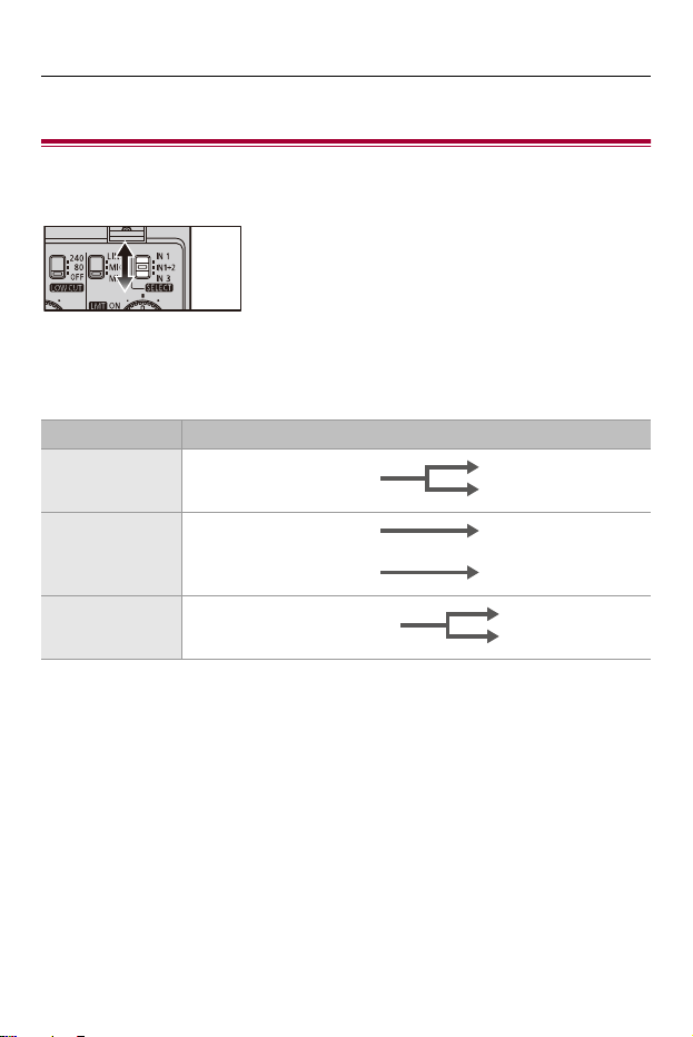
Setting the Recording Channels
Set the recording channels to match the settings in the digital camera
menu ([4ch Audio Recording]).
When [4ch Audio Recording] Is [OFF]
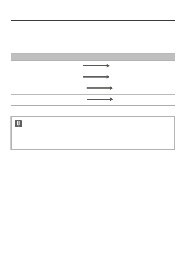
Select the input audio to be recorded to CH1/CH2 with the SELECT switch.
Settings Audio recorded with CH1/CH2
[IN1]
[IN1+2]
[IN3]
INPUT1
CH1
CH2
INPUT1 CH1
INPUT2 CH2
INPUT3 (L/R)
CH1
CH2
Using the XLR Microphone Adaptor – Setting the Recording Channels
26
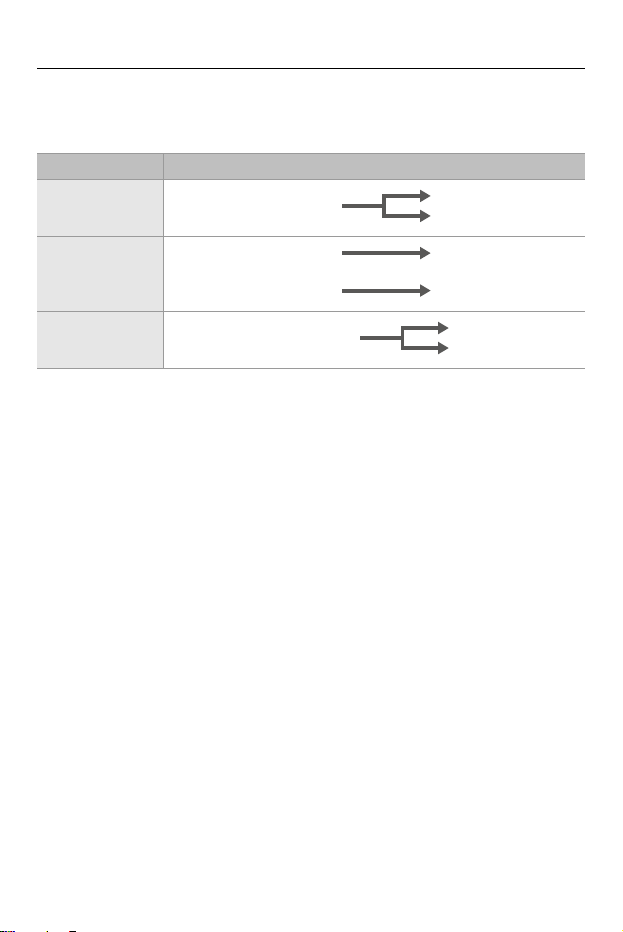
When [4ch Audio Recording] Is [XLR+CAMERA]
Select the input audio to be recorded to CH1/CH2 with the SELECT switch.
•
The input audio from the built-in microphone of the digital camera or the external
microphone connected to the digital camera is recorded to CH3/CH4.
Settings Audio recorded with CH1/CH2
[IN1]
[IN1+2]
[IN3]
INPUT1
CH1
CH2
INPUT1 CH1
INPUT2 CH2
INPUT3 (L/R)
CH1
CH2
Using the XLR Microphone Adaptor – Setting the Recording Channels
27
When [4ch Audio Recording] Is [XLR]
Irrespective of the position of the SELECT switch, the input audio recorded
to each channel is fixed.
Audio to be Recorded to CH1/CH2/CH3/CH4
• If there is no [4ch Audio Recording] in the menus of the digital camera, it is not
possible to record 4-channel audio with only the microphone connected to this
unit.
INPUT1 CH1
INPUT2 CH2
INPUT3 (L) CH3
INPUT3 (R) CH4
Using the XLR Microphone Adaptor – Setting Input Gain
28
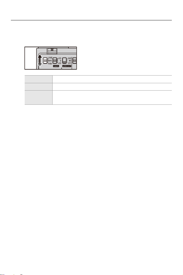
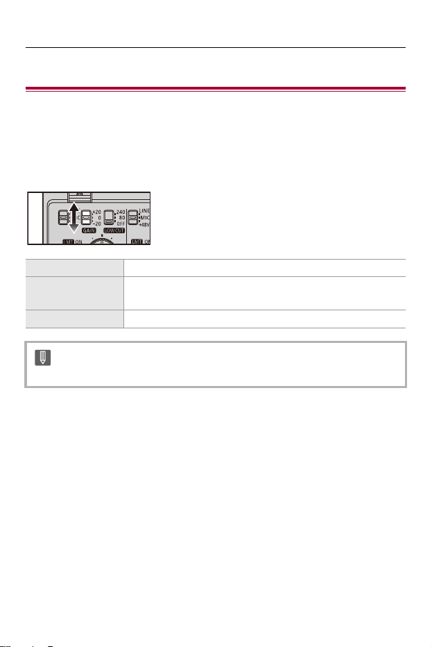
Setting Input Gain
You can change the input gain with the GAIN switch (INPUT1/INPUT2)
when the LINE/MIC/i48V switch (INPUT1/INPUT2) is set to [MIC] or
[i48V].
Set the input gain with the GAIN switch (INPUT1/INPUT2).
[i20] i20 dB
[0]
0dB
(Default setting, standard level: j40 dBu)
[j20] j20 dB
• Input gain cannot be changed during 32-bit float recording.
Using the XLR Microphone Adaptor – Setting the Recording Level
29
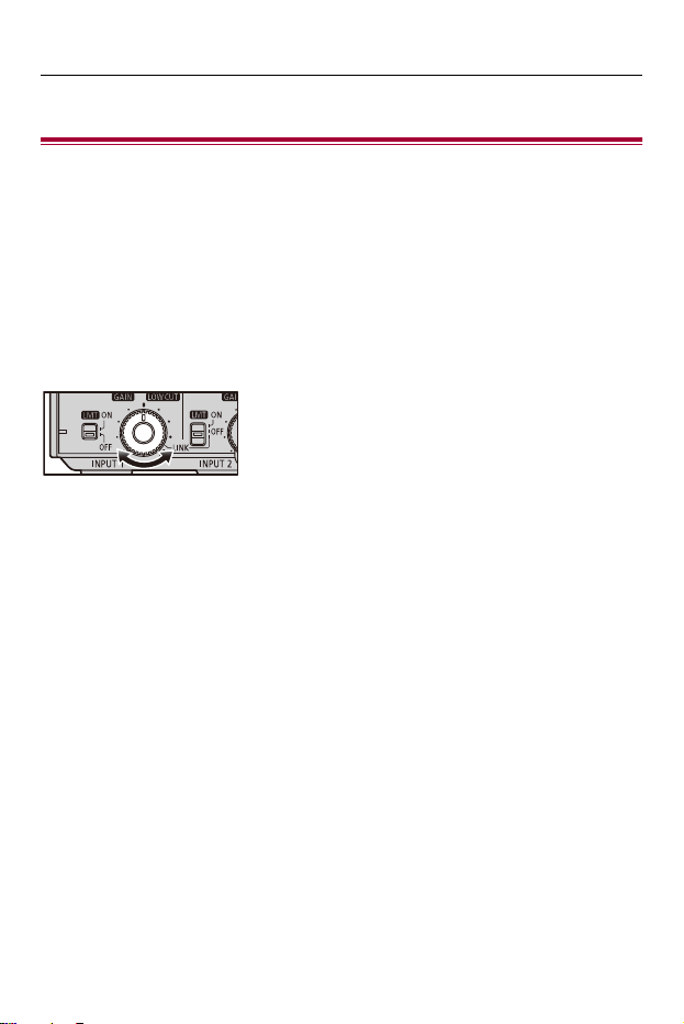
Setting the Recording Level
Set the recording level for audio that is input through the input terminals
(INPUT1, INPUT2, INPUT3).
Turn the AUDIO LEVEL dial (INPUT1/INPUT2/INPUT3) to set
the recording level (volume).
• Setting the level while checking with headphones connected to the digital camera or
the digital camera microphone level display is recommended.
• Sound is muted if you turn the dial all the way to the left.

Using the XLR Microphone Adaptor – Setting the Recording Level
30
Matching the Recording Levels of INPUT1 and INPUT2
Set the LMT/LINK switch (INPUT2) to [LINK]. The recording levels for both
INPUT1 and INPUT2 can be set at the same time with the AUDIO LEVEL
dial (INPUT1). The setting of the LMT switch (INPUT1) is also applied to
INPUT2.
Adjust the recording level automatically
Set the LMT switch (INPUT1/INPUT3) or the LMT/LINK switch (INPUT2) to
[ON]. At high volumes, the recording level is decreased automatically to
reduce distortion with the sound.
•
The recording level of the built-in microphone of the digital camera and the [MIC]
terminal cannot be set.
• Recording levels other than mute cannot be changed during 32-bit float
recording.
• The recording volume may vary if you switch between float format and linear
format.
Using the XLR Microphone Adaptor – Decrease Noise Caused by Wind or Handling
31
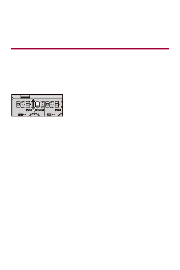
Decrease Noise Caused by Wind or
Handling
Noise caused by wind or handling is reduced by cutting out low-frequency
components that are input to the XLR terminals (INPUT1, INPUT2).
Set the LOW CUT switch (INPUT1/INPUT2) to [80] or [240].
• Select based on the type of noise.


Materials – Cautions for Use
33
Cautions for Use
About the unit
Do not use this unit near radio transmitters or high-voltage lines.
•
Noise may be present in images and sound recorded near radio transmitters or
high-voltage lines. Perform recording in locations away from them. The level of noise
varies depending on the XLR microphone used.
Keep the unit away from insecticide sprays and other volatile
substances.
•
Exposure to such substances may cause damage to the external case and the text
and symbols printed on the unit.
• Do not leave the unit in contact with any items made of rubber or PVC for prolonged
periods of time.

Materials – Cautions for Use
34
Do not carry the unit with your hands while it is still attached to a
digital camera.
•
Under no circumstances should the unit be used or stored in any of the following
locations since doing so may cause trouble in operation or malfunctioning:
– In direct sunlight or on a beach in summer
– In locations with high temperatures and humidity levels or where changes in
temperature and humidity are acute
– In locations with high concentrations of sand, dust or dirt
– Where there is fire
– Near heaters, air conditioners or humidifiers
– Where water may make the unit wet
– Where there is vibration
– Inside a vehicle
• Do not drop the unit, knock it into other objects or subject it to any other kind of
strong impact or shock.
• When recording a motion picture, the digital camera or lens sounds or other
operating noise may be recorded. If the sound from the lens is particularly bothering,
set the camera to manual focus during use. If the operating noise is particularly
bothering, position the microphone away from the digital camera during use.
• If the terminals are dirty they can cause faulty connections. Wipe clean with a soft
dry cloth before connecting.
• Do not attach or remove cables with the power of the digital camera turned [ON].
• If you start video recording immediately after turning on the digital camera, a period
with no sound may be recorded at the beginning.
• Before use, check that the XLR microphone adaptor is recording normally.
• Do not disassemble or modify this unit.

Materials – Cautions for Use
35
Cleaning
When cleaning, wipe the unit with a dry soft cloth.
•
When the unit is soiled badly, it can be cleaned by wiping the dirt off with a wrung wet
cloth, and then with a dry cloth.
• Do not use solvents such as benzine, thinner, alcohol, kitchen detergents, etc., to
clean the unit, as these may damage the external case and the text and symbols
printed on the unit.
• When using a chemical cloth, be sure to follow the accompanying instructions.

Materials – Specifications
36
Specifications
The specifications are subject to change for performance enhancement.
INPUT1 terminal, INPUT2 terminal
≥ Input terminal
XLR3-pin, female
≥ Standard input level
LINE: 0 dBu
MIC, i48V: j40 dBu
(0 dBu=0.775 Vrms)
≥ Standard recording level
j12 dBFS (at the standard input)
≥ Frequency characteristic
20 Hz to 40 kHz, i1/j1 dB (Fs= during 96 kHz, during LINE)
≥ Phantom power source
48 V

Materials – Specifications
37
INPUT3 terminal
≥ Input terminal
‰3.5 mm stereo mini jack
≥ Standard input level
LINE: j10 dBV
MIC, MIC (plug-in power): j40 dBV
(0 dBV=1 Vrms)
≥ Standard recording level
j12 dBFS (at the standard input)
≥ Frequency characteristic
20 Hz to 40 kHz, i1/j1 dB (Fs= during 96 kHz, during LINE)
≥ Plug-in power
2.5 V
Sampling frequency/bit length/number of recording channels
≥ During linear recording
48 kHz/24 bit/2ch, 96 kHz/24 bit/2ch
(Select one of INPUT1, INPUT1+2, or INPUT3)
48 kHz/24 bit/4ch
≥ During float recording
48 kHz/32 bit/2ch, 96 kHz/32 bit/2ch
(Select one of INPUT1, INPUT1+2, or INPUT3)
48 kHz/32 bit/4ch
Materials – Specifications
38
External dimensions
Approx. 61.2 mm (W)k60.9 mm (H)k92.0 mm (D)
[2.41q (W)k2.40q (H)k3.63q (D)]
(microphone holder not attached)
(excluding the projecting parts)
Approx. 94.6 mm (W)k106.2 mm (H)k92.0 mm (D)
[3.73q (W)k4.19q (H)k3.63q (D)]
(microphone holder attached)
(excluding the projecting parts)
Mass (weight)
Approx. 158 g/0.35 lb (microphone holder not attached)
Approx. 192
g/0.43 lb (microphone holder attached)
Operating temperature
j10 °C to 40 °C (14 oF to 104 oF)
Operating humidity
10 %RH to 80 %RH
The symbols on this product (including the accessories) represent the
following:
DC