
2
Specifications
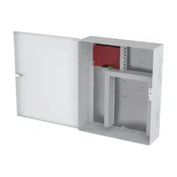
Product overview
1
2
3 (only included in AXIS TA1202 Enclosure with Power Unit and FAI)
4 Dedicated space for AXIS TA1101-B (x 8)
5
6 Dedicated space for AXIS A1710-B
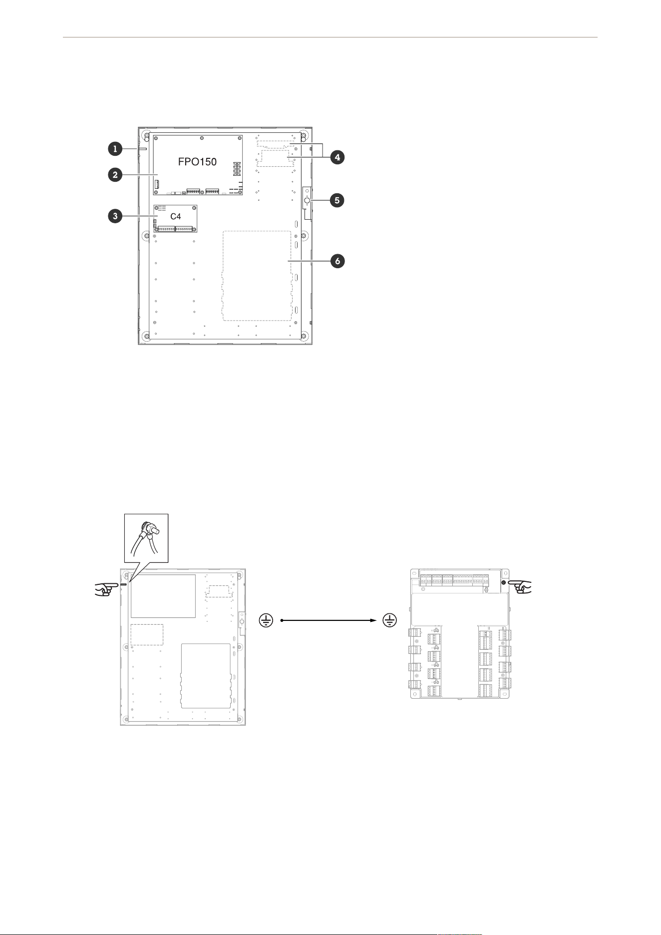
Grounding
Use the included grounding wire to connect the enclosure to the door controller.
Door controller to enclosure ground
Tampering switch
Connect wires (included) from the tampering switch in the enclosure to the door controller to detect if someone
tries to cause damage.
AXIS TA1202 Enclosure with Power Unit
3
Tampering switch to door controller
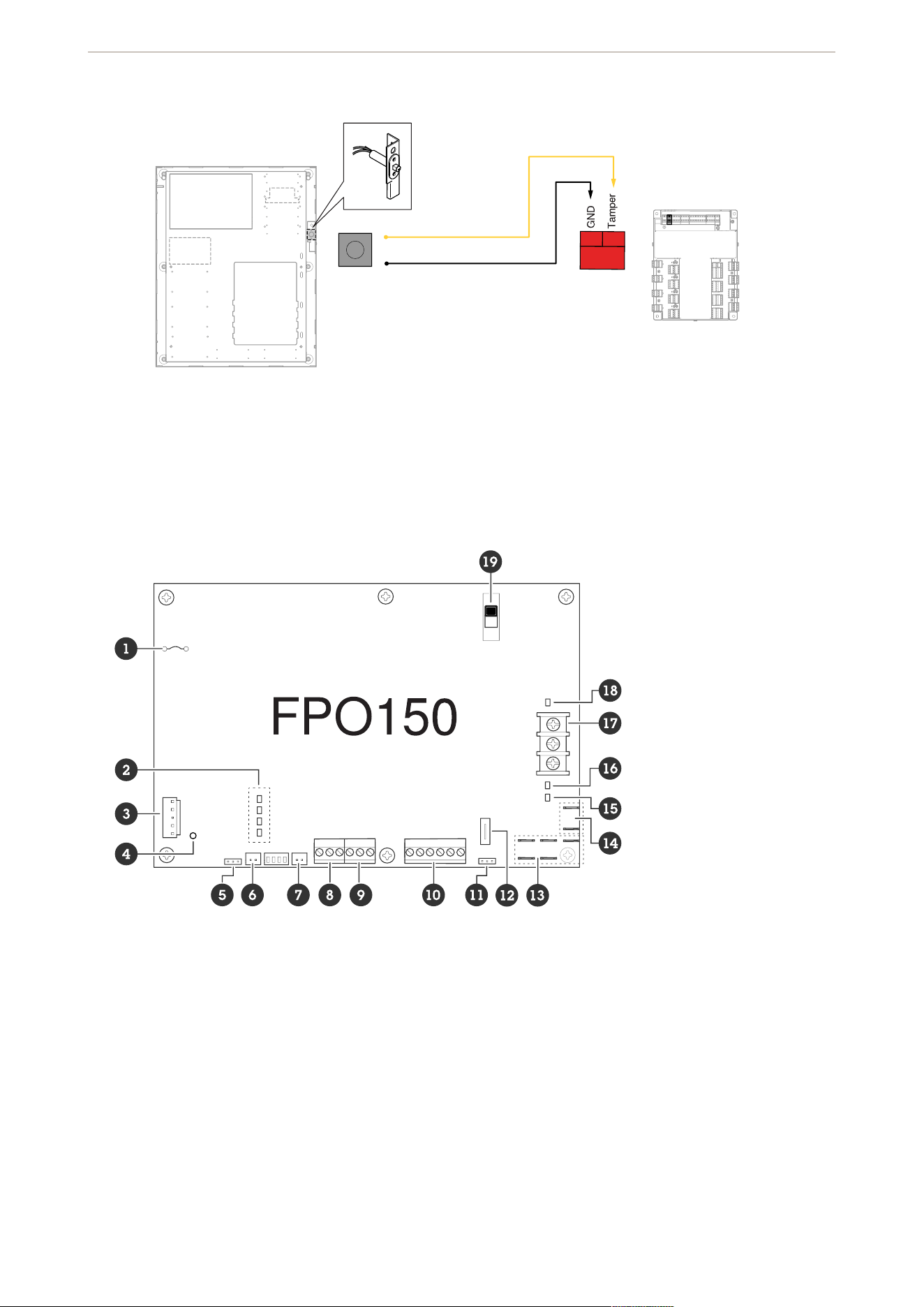
FPO150
1
2
3
4
5 Earth ground fault detector
6 External AC LED connector
7
8 System fault contact, see
9 AC fault contact, see
10 FAI input connector
11 Battery presence detector
12
13 FlexConnect power connector
14
15
AXIS TA1202 Enclosure with Power Unit
4
16 DC2 output status LED, see
17
18 DC1 output status LED, see
19
For more details about the FPO board, see LifeSafety Power®’s Installation Manual.
Connectors and terminals
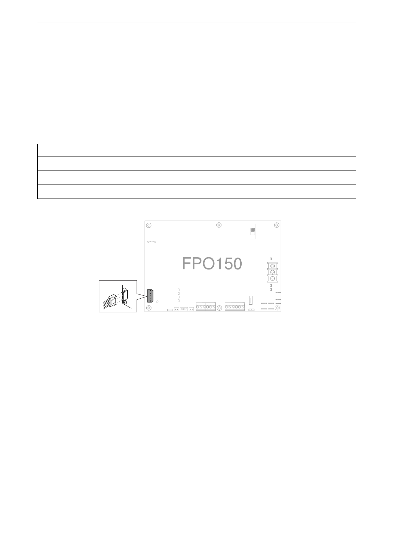
AC input
Connector for AC power input. It accepts the included three-wire connector harness. Cut the (JP1) if the FPO is
powered by 230 VAC. Connections are by wire nut:
120 VAC 230 VAC
White: neutral White: phase 2
Green: earth ground Green: earth ground
Black: hot Black: phase 1
AC input connection
Inductor
For the 230 VAC model, connect the included inductor to the AC input and secure it to the inside of the
enclosure.
AXIS TA1202 Enclosure with Power Unit
5
FlexIO connector
Connector supplying the FAI and fault status between the FPO power supply and any accessory boards in the
system. The appropriate cable is supplied with the accessory boards.
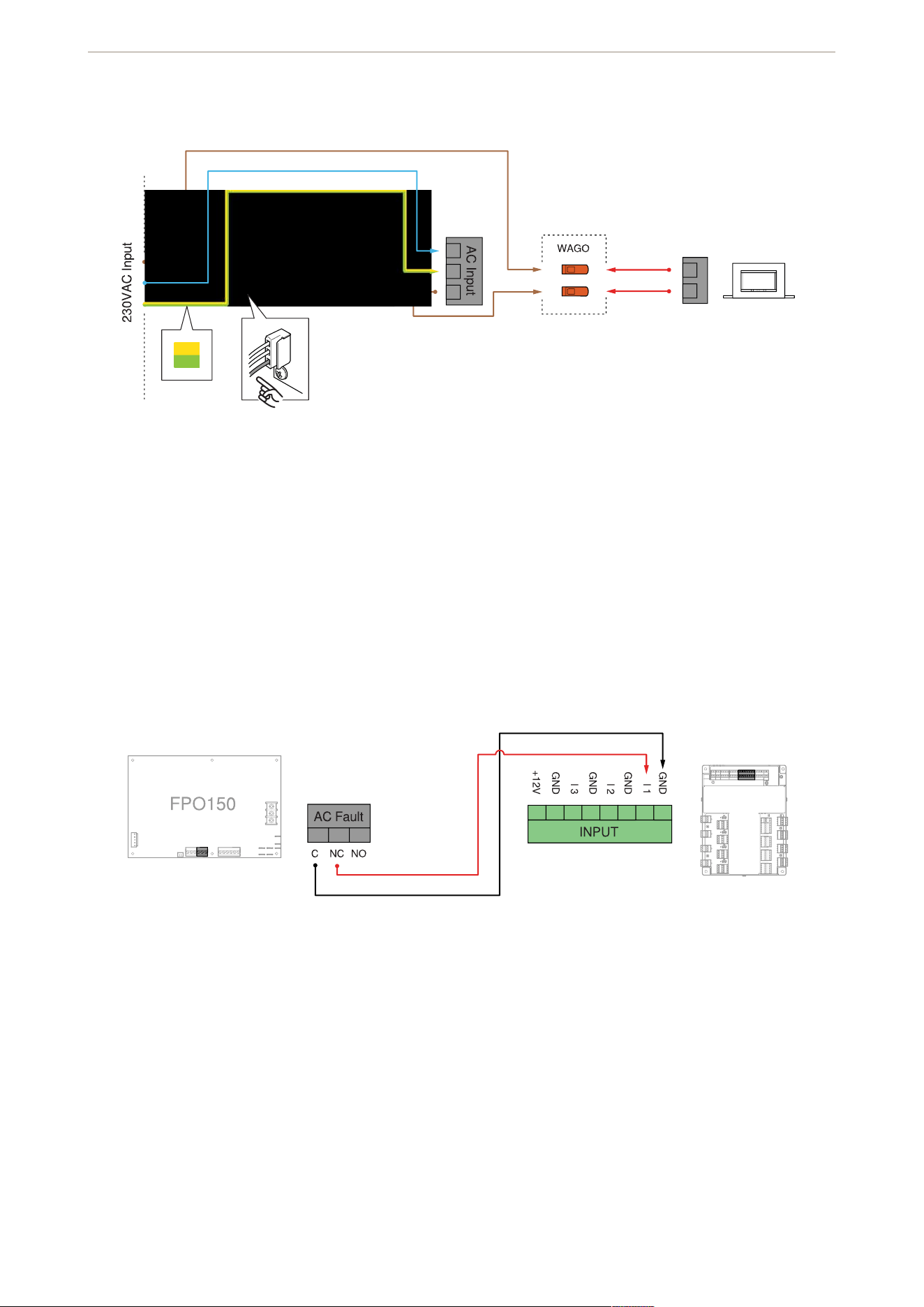
Fault output connectors
Terminals providing the system fault and AC fault contact outputs. The terminals are removable and are labeled
on the PC board in the non-powered (fault) state.
AC fault to door controller
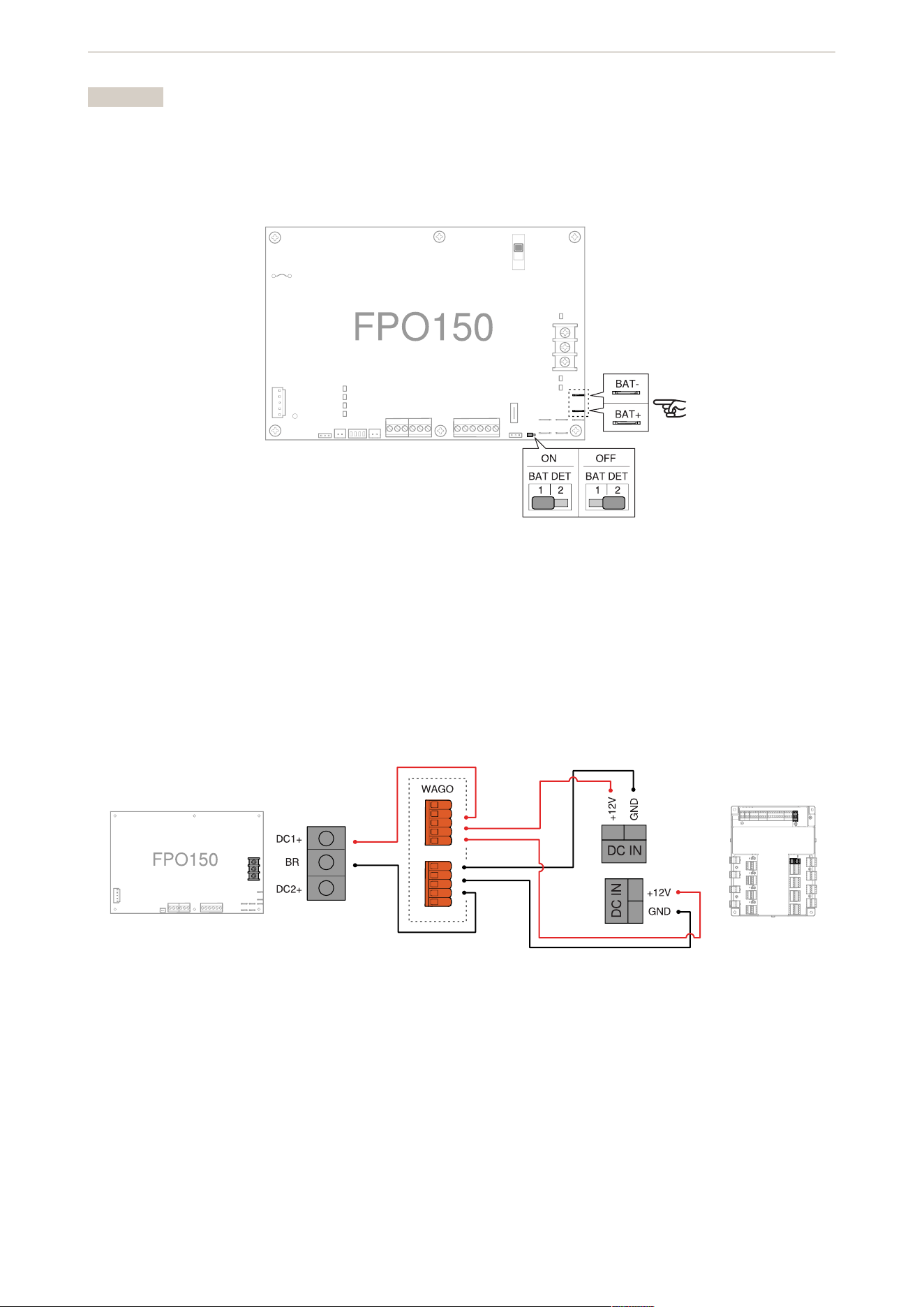
Battery connector
Faston connectors for connecting the backup battery set. Pre-terminated battery leads are included. If you don’t
plan to use any battery set, make sure the battery presence detection (BAT DET) jumper is off (set to position 2)
to prevent that a fault condition occurs. The FPO has built-in low battery disconnect to prevent deep discharge
of the batteries and to prevent damage to sensitive equipment.
AXIS TA1202 Enclosure with Power Unit
6
Important
• Select the proper battery type before you connect a battery set to the FPO.
• The FPO requires a 12 V battery set.
• To avoid damaging the system, observe polarity.
Battery to FPO and battery jumper
DC1 output
The main DC output of the FPO power supply. The full current of the FPO is available on this terminal at all times
and is unaffected by the FAI input.
Door controller power
Switches
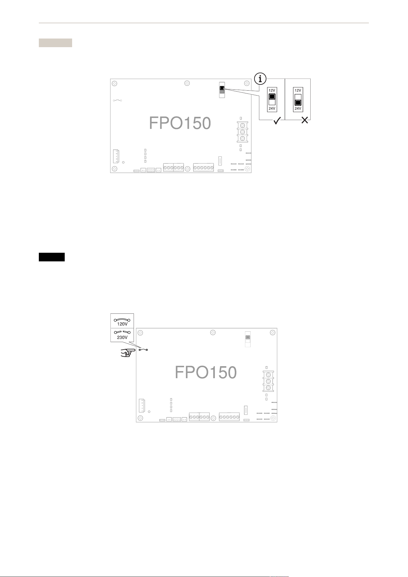
Output voltage switch
Switch for selecting the output voltage of the FPO power supply.
AXIS TA1202 Enclosure with Power Unit
7
Important
Set the switch to 12V.
Jumpers
AC input voltage jumper
Jumper for configuring the FPO for the AC input voltage to be used.
NOTICE
• The jumper must be intact for 120 VAC input. If you have the 120 VAC enclosure, make sure the jumper
is intact.
• The jumper must be cut and removed for 230 VAC input. If you have the 230 VAC enclosure, make sure
the jumper is cut and removed.
Fuses
Battery fuse
Fuse in series with the battery connection.
Replace only with an ATM 15A fuse.
AXIS TA1202 Enclosure with Power Unit

8
LED indicators
AC input status LED
Status LED Indication
AC ON Green when any AC voltage is present on the AC
input. It doesn’t indicate that the voltage is sufficient
for proper operation.
WARNING
To prevent electric shock, always use a meter to
verify the absence of AC power before you service
the equipment.
FAI and fault status LEDs
Status LED Indication
FAI Red when a valid FAI signal is received on the FAI
input terminals.
GND FLT Yellow when an impedance is detected between earth
ground and any voltage output or DC common. A
ground fault will also light the SYS FLT LED.
AC FLT Yellow when the AC input voltage is low or missing
SYS FLT Yellow when a system issue is detected by the FPO.
Issues include:
• missing battery (if the battery detection
connection, BAT DET, jumper is ON)
• earth ground fault (if the earth ground fault
detection, EARTH GND DET, jumper is ON)
• battery voltage out of range
• DC output voltage out of range
• broken fuse
• accessory board fault
• internal fault
Backup battery status LED
Status LED Indication
REV BAT Yellow if the backup battery set is connected in the
reverse polarity. When lit, the battery fuse is broken
and the SYS FLT LED is also lit.
AXIS TA1202 Enclosure with Power Unit
9
DC output status LEDs
Status LED Indication
DC1 Green when the output is set to 12V (blue if set to
24V) and when voltage is available on the output
terminal.
DC2 Green when the output is set to 12V (blue if set to
24V) and when voltage is available on the output
terminal.
Unlit if the output is disabled through the FAI input.
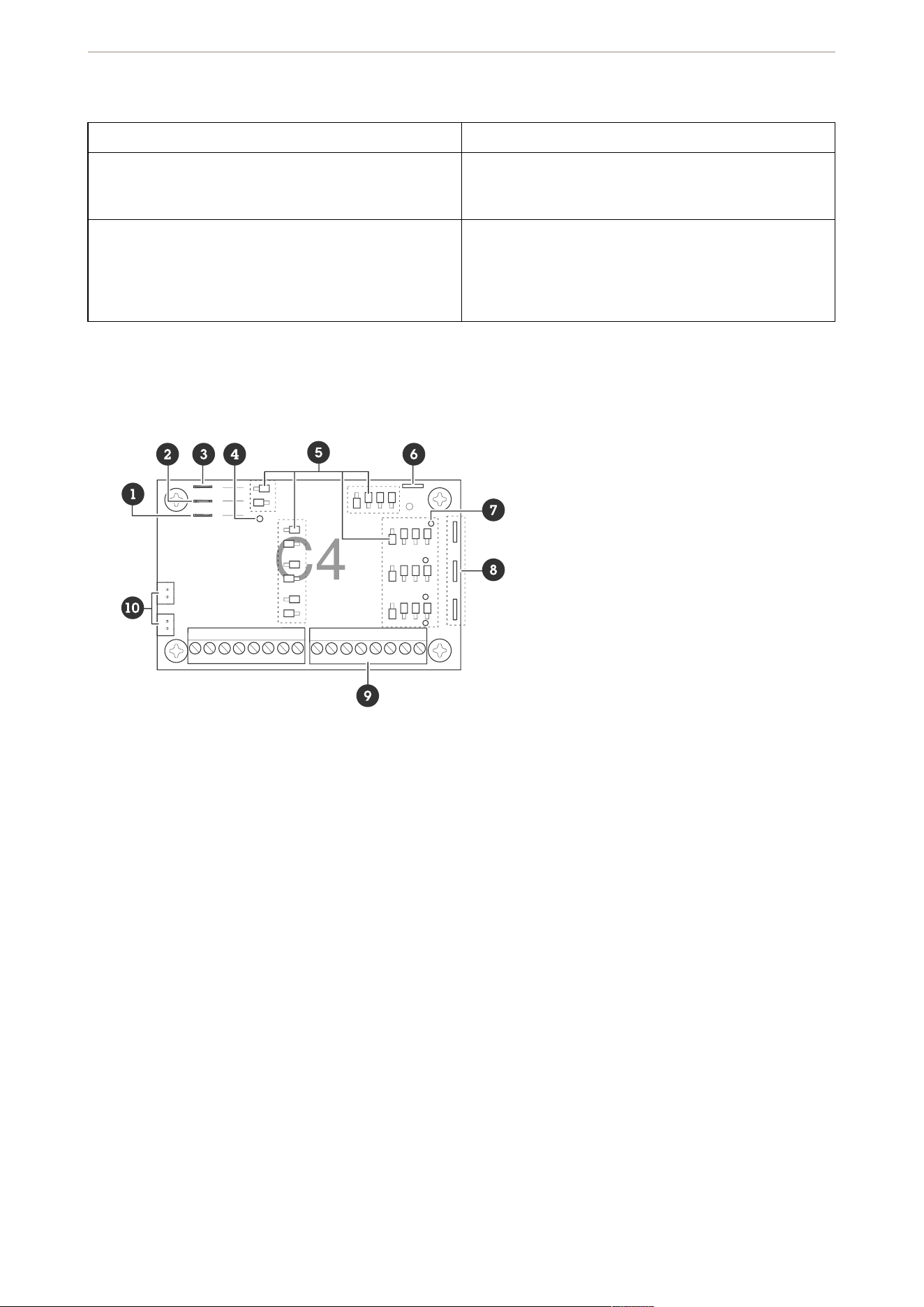
C4
1 BR connectors, see
2 B2 connectors, see
3 B1 connectors, see
4
5
6
7
8
9
10
For more details about the C4 board, see LifeSafety Power®’s Installation Manual
Connectors and terminals
Power connectors
B1
Connector for the B1 bus in the system. The voltage on the B1 bus comes from the FPO power supply. This
voltage is directed to any outputs whose yellow jumper (jumper D) is set in the B1 position.
B2
AXIS TA1202 Enclosure with Power Unit
10
Connector for the B2 bus in the system. The voltage on the B2 bus comes from the FPO power supply. This
voltage is directed to any outputs whose yellow jumper (jumper D) is set in the B2 position. If you use the board
in a single voltage system, these fastons can be left unused.
BR
The DC common bus in the system. All DC boards in the system must have their BR fastons wired together for
proper operation.
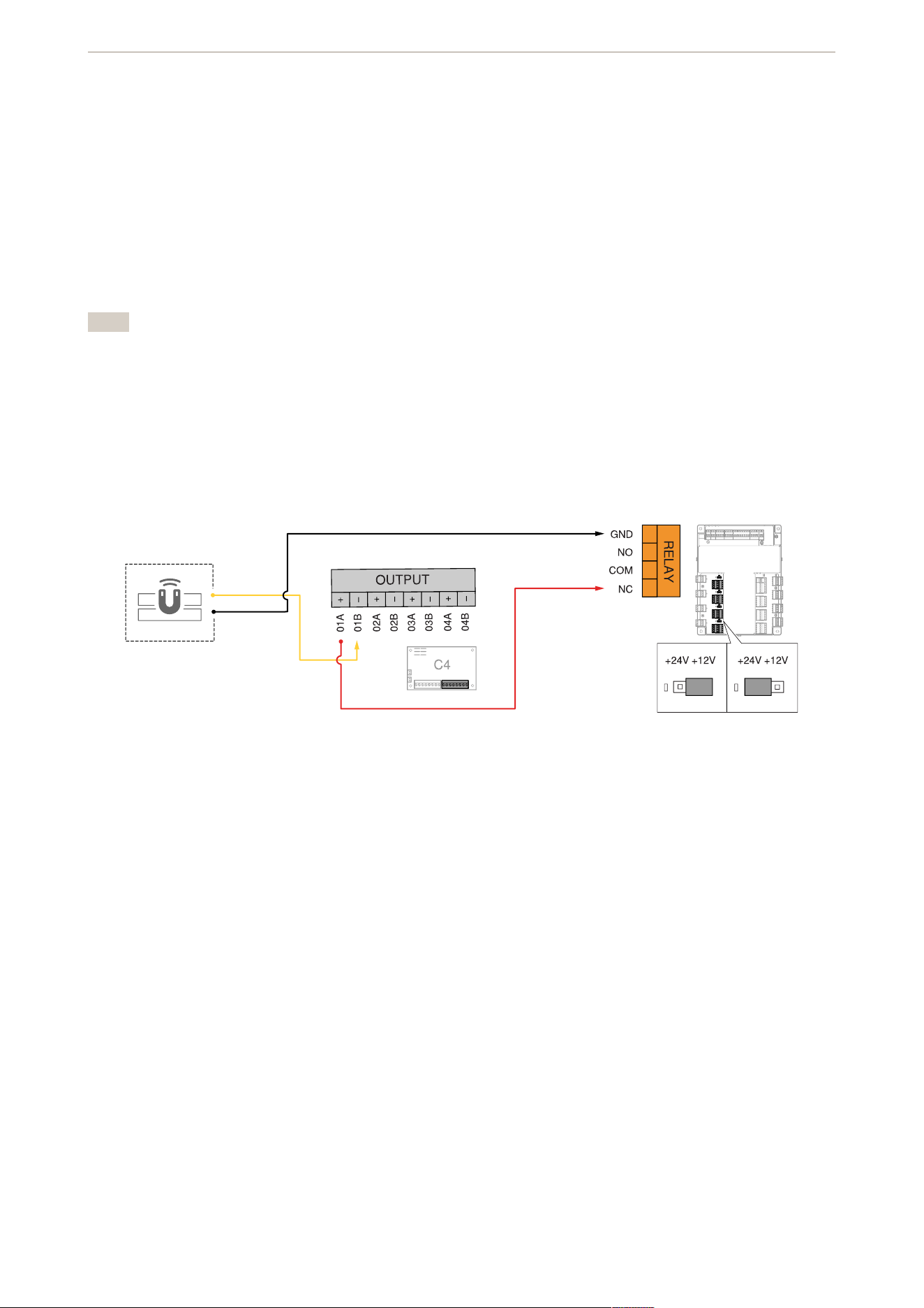
Zone outputs
Removable output terminal strips. The terminal strips are labeled on the PC board.
Note
• Relay contact outputs are across the A and B terminals. Use the white (F) configuration jumper to set as
fail-safe or fail-secure.
• Voltage (wet) outputs are across the A and B terminals. DC common is terminal A. Positive is terminal B.
• The board has reverse protection diodes across each output. If there is a delay on a lock release, or if
you’re using it as a dry relay contact output, you can remove the diode from the circuit.
Door relay to C4
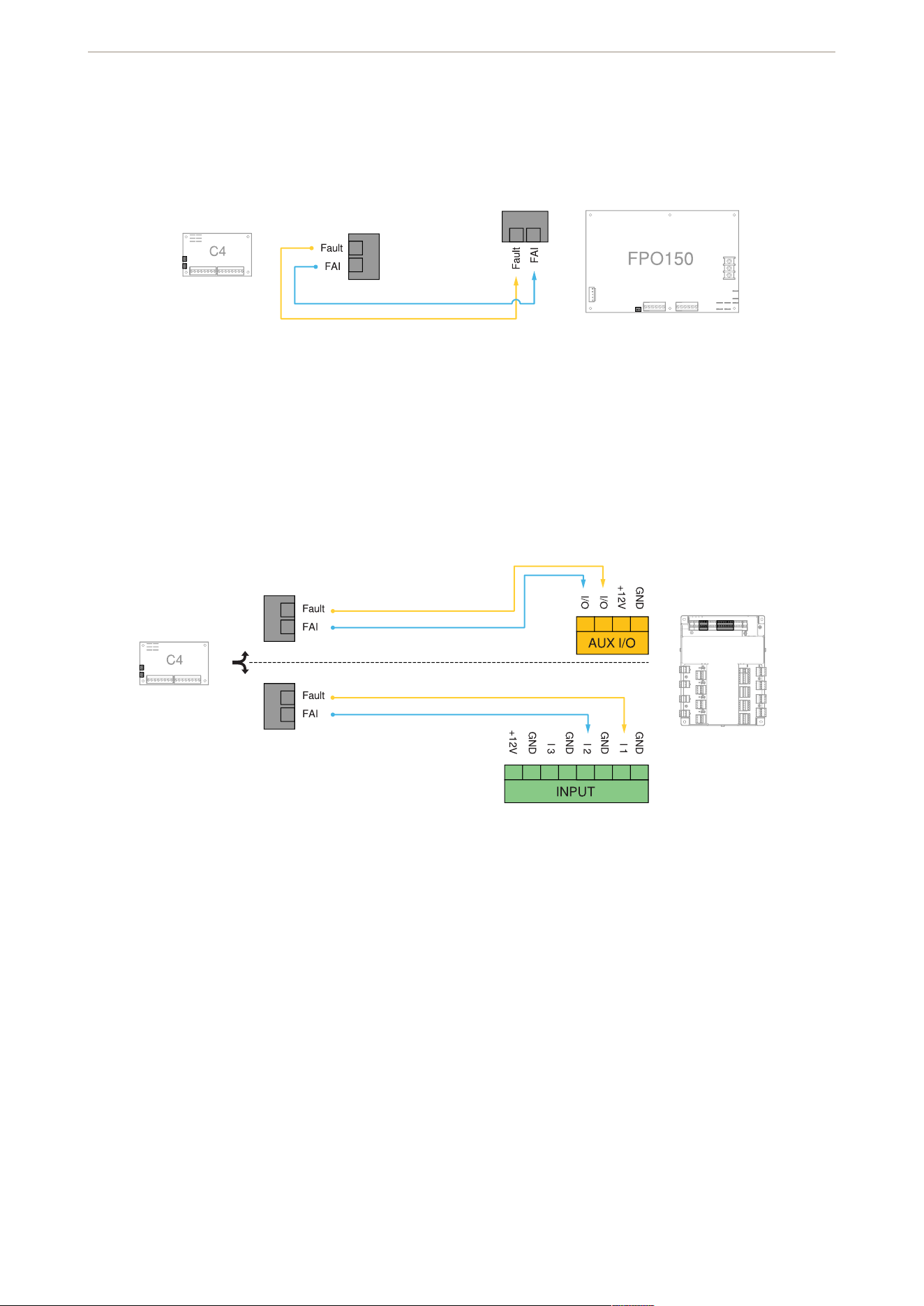
FlexIO connectors
Connectors passing the FAI and fault signals to and from the C4 board and passing the FlexIO bus on to other
accessory boards in the system.
AXIS TA1202 Enclosure with Power Unit
11
FlexIO from C4 to FPO
FlexIO from C4 to door controller
Jumpers
Configuration jumpers
Jumpers for programming each zone’s input, output, and FAI operation. Jumpers are color coded and the
numbers correspond to the zone numbers. For example, 1A is jumper A for zone 1.
AXIS TA1202 Enclosure with Power Unit

12
Red (A) – zone FAI enable
Enable or disable FAI for the selected zone. The FAI control input is on the FPO power supply board.
Pos 1: FAI enabled. In this position, the zone’s output inverts when the input is active. This is typically used to
drop power to magnetic locks.
Pos 2: FAI disabled. In this position, the FAI won’t have any effect on the zone’s output.
Blue (B) – input invert
Switch between a fail-safe and a fail-secure input. Adjust the jumper so the zone’s output LED flashes when the
door is unlocked.
Pos 1: fail-safe. This position provides an NC contact input (contact opens to unlock door) or for a voltage input
where the voltage is removed to unlock the door.
Pos 2: fail-secure. This position provides an NO contact input (contact closes to unlock door) or for a voltage
input where the voltage is applied to unlock the door.
Black (C and E) – wet or dry output
Select whether the output is a relay contact output or a voltage output.
Important
Both jumpers must be set to the same position for proper operation.
Pos 1: relay contact output. By placing both jumpers in this position, the zone’s output is set as a relay contact
output.
Pos 2: voltage output. By placing both jumpers in this position, the zone’s output is set to output the voltage of
the bus selected by the yellow jumper (D).
Yellow (D) – voltage bus selection
The board can accept up to two power supply inputs connected to B1 and B2. Use this jumper to select which of
the two power supply inputs to use for the zone’s output. If only a single power supply is used, set the jumper to
pos 1.
Note
If the zone’s output is set as a relay contact output, this jumper has no effect.
Pos 1: B1 bus. This position selects the power supply connected to the B1 input.
Pos 2: B2 bus. This position selects the power supply connected to the B2 input.
White (F) – output invert
Select a fail-safe or fail-secure output. Adjust the jumper so the door is unlocked when the zone output LED
flashes (zone active).
Pos 1: NO – voltage when input is activated. In this position, the output terminals connect through the NC
contact if set for a relay contact output, or outputs a voltage when the input is activated.
AXIS TA1202 Enclosure with Power Unit

13
Pos 2: NC – voltage when input is deactivated. In this position, the output terminals connect through the NO
contact if set for a relay contact output, or doesn’t output a voltage when the input is activated. This position is
typically used for magnetic locks.
Jumper color Correct position
Red Pos 1 (FAI enabled)
Blue Pos 2 (fail-safe setup)
Black Pos 1 (dry contacts)
Yellow Pos 1 (12V power supply)
White Pos 2 (fail-safe setup)
Fuses
Output fuses
Fuses for each zone output. Fuse numbers correspond to zone numbers. For example, F1 is the fuse for zone
output OUT1.
LED indicators
Fault status LED
Status LED Indication
FAULT Yellow when the board has detected a broken output
fuse. This fault condition also transmits to the FPO
power supply.
Output status LEDs
Status LED Indication
Output (1–8) Green when the output is set to 12V (blue if set to
24V).
Steady: door locked (fuse or PTC intact).
Flashing: door unlocked (either due to zone input or
FAI).
Unlit: fuse or PTC open.
Note
If an output LED operates opposite to what’s
expected (flashing in normal state, steady when
the input is activated) but the output terminals
behave as expected, then jumpers B and F should
be placed into the opposite position.
AXIS TA1202 Enclosure with Power Unit
14
Connect equipment
For electrical wiring drawings and other documentation related to AXIS A17 series, see axis.com/products/axis-
a17-series.
For electrical wiring drawings and other documentation related to AXIS TA1101-B Wiegand to OSDP Converter,
see axis.com/products/axis-ta1101-b-wiegand-to-osdp-converter/support#support-resources
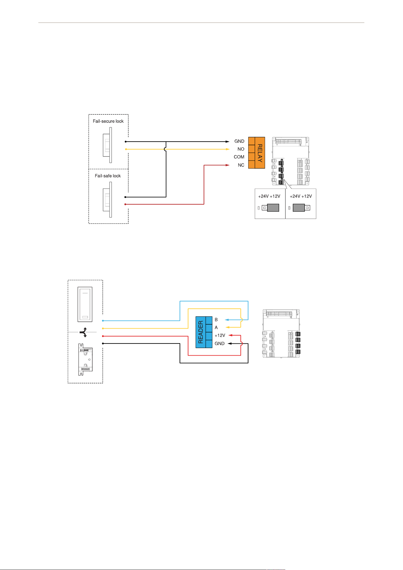
Door relay
Reader
AXIS TA1202 Enclosure with Power Unit
15
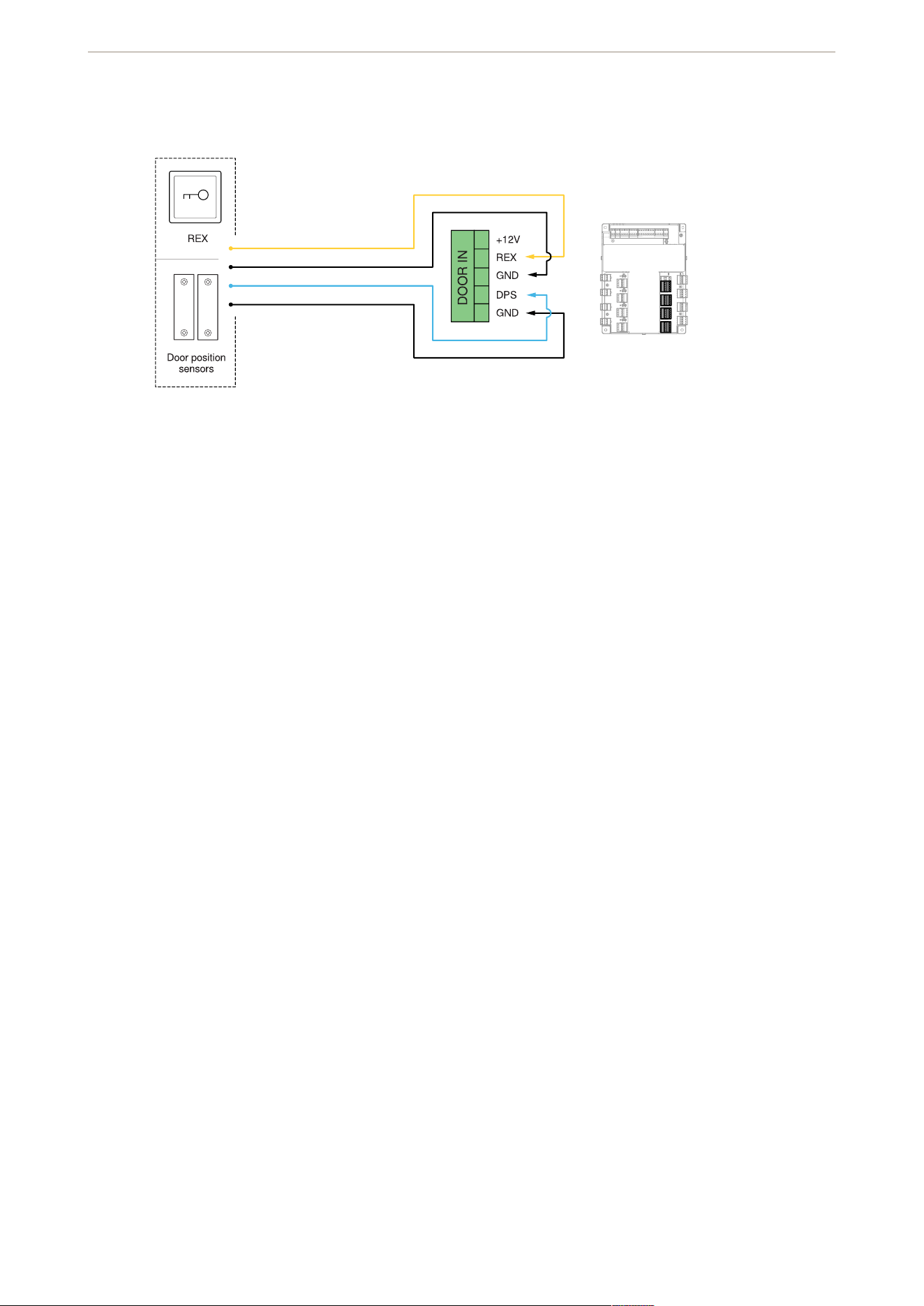
Door inputs
AXIS TA1202 Enclosure with Power Unit

.
T10228371
2025-10 (M1.17)
© 2025 Axis Communications AB