CUB CADET LLC, P.O. BOX 361131 CLEVELAND, OHIO 44136-0019
Printed In USA
OperatOr’s Manual
Safe Operation Practices • Set-Up • Operation • Maintenance • Service • Troubleshooting • Warranty
WARNING
READ AND FOLLOW ALL SAFETY RULES AND INSTRUCTIONS IN THIS MANUAL
BEFORE ATTEMPTING TO OPERATE THIS MACHINE.
FAILURE TO COMPLY WITH THESE INSTRUCTIONS MAY RESULT IN PERSONAL INJURY.
Form No. 769-06325B
(May 2, 2012)
Utility Vehicle — Volunteer

Record Product Information
Before setting up and operating your new equipment, please
locate the model plate on the equipment and record the
information in the provided area to the right. You can locate the
model plate under the operator’s seat. Flip the seat forward to
view the model plate. This information will be necessary, should
you seek technical support via our web site or with your local
Cub Cadet dealer.
Model NuMber
Serial NuMber
Product Registration and Customer Support
Please register your product on our website, www.cubcadet.com.
If you have difficulty assembling this product or have any questions regarding the controls, operation, or maintenance of
this machine, you can seek help from the experts. Choose from the options below:
◊ Visit us on the web at www.cubcadet.com
See How-to Maintenance and Parts Installation Videos at www.cubcadet.com/tutorials
◊ Locate your nearest Cub Cadet Dealer at (877) 282-8684
◊ Write to Cub Cadet LLC • P.O. Box 361131 • Cleveland, OH • 44136-0019
Thank you for purchasing a Cub Cadet Utility Vehicle. It was
carefully engineered to provide excellent performance when
properly operated and maintained.
Please read this entire manual prior to operating the equipment.
It instructs you how to safely and easily set up, operate and
maintain your machine. Please be sure that you, and any other
persons who will operate the machine, carefully follow the
recommended safety practices at all times. Failure to do so could
result in personal injury or property damage.
All information in this manual is relative to the most recent
product information available at the time of printing. Review
this manual frequently to familiarize yourself with the machine,
its features and operation. Please be aware that this Operator’s
Manual may cover a range of product specifications for various
models. Characteristics and features discussed and/or illustrated
in this manual may not be applicable to all models. We reserve
the right to change product specifications, designs and
equipment without notice and without incurring obligation.
If applicable, the power testing information used to establish
the power rating of the engine equipped on this machine can be
found at www.opei.org or the engine manufacturer’s web site.
If you have any problems or questions concerning the machine,
phone your local Cub Cadet dealer or contact us directly. Cub
Cadet’s Customer Support telephone numbers, website address
and mailing address can be found on this page. We want to
ensure your complete satisfaction at all times.
Throughout this manual, all references to right and left side of the
machine are observed from the operating position.
Thank You
To The Owner
1
2
Safe Operation Practices ........................................ 3
Controls & Features ................................................. 8
Operation ................................................................11
Maintenance & Adjustment .................................14
Service .....................................................................18
Maintenance Chart ............................................... 20
Accessories ..............................................................21
Specifications ......................................................... 22
Troubleshooting .................................................... 23
Warranty ................................................................ 28
Table of Contents
Important Safe Operation Practices
2
3
Operation
General Operation
1. Read, understand, and follow all instructions on the vehicle
and in the manual before attempting to operate or service
vehicle. Keep this manual in a safe place for future and
regular reference and for ordering replacement parts.
2. This is an off-road utility vehicle and it should not be
operated on public highways. Know and comply with all
laws and regulations governing the use of off-highway
vehicles in your area.
3. This vehicle handles and maneuvers differently than
a normal passenger car. Sharp high speed turns and
abrupt maneuvers can cause vehicle to roll over or go out
of control. Slow down when turning and avoid abrupt
maneuvers.
4. Handling and maneuvering characteristics of vehicle
change depending upon cargo load. Heavy loads affect
steering, braking, stability, and overall handling of vehicle.
5. Be familiar with all instructions and controls and their
proper operation before starting vehicle.
6. Never allow adults to operate this vehicle without proper
instruction.
7. Never allow children under 16 years old to operate this
vehicle. Children 16 years old and over should read and
understand the operation instructions and safety rules in
this manual and should be trained and supervised by a
parent.
8. Watch for traffic when operating near or crossing
roadways. This vehicle is not intended for use on any public
roadway.
9. Do not operate this vehicle while under the influence of
alcohol or drugs.
10. Never carry more than one passenger. This vehicle is
designed to carry the driver and one passenger only. No
riders are allowed in cargo box or anywhere else on vehicle,
except in the driver and passenger seats.
11. Keep all body parts (i.e. head, arms, hands, legs, feet) inside
vehicle when vehicle is in motion.
12. Always remain seated and keep both hands on the steering
wheel when driving the vehicle.
13. Sit on the center of the seat and keep both feet within the
foot platform perimeter. Clean foot platform if dirty and
remove any debris from around foot controls, e.g. brake
pedal.
14. Do not misuse the utility vehicle. It is an utility vehicle, not
a recreation vehicle or toy. Recreational riding can lead to
accidents, severe bodily injury or death.
WARNING: This symbol points out important safety instructions which, if not followed,
could endanger the personal safety and/or property of yourself and others. Read and follow
all instructions in this manual before attempting to operate this machine. Failure to comply
with these instructions may result in personal injury.
When you see this symbol. HEED ITS WARNING!
DANGER: This machine was built to be operated according to the rules for safe operation in
this manual. As with any type of power equipment, carelessness or error on the part of the
operator can result in serious injury. Failure to observe the following safety instructions could
result in serious injury or death.
CALIFORNIA PROPOSITION 65
WARNING: Engine Exhaust, some of its constituents, and certain vehicle components
contain or emit chemicals known to State of California to cause cancer and birth defects
or other reproductive harm.
WARNING: Battery posts, terminals, and related accessories contain lead and lead
compounds, chemicals known to the State of California to cause cancer and reproductive
harm. Wash hands after handling

4 Section 2 — important Safe operation practiceS
15. Inspect area around vehicle before moving, especially in
reverse. Back up slowly. Always look down and behind
before and while backing to avoid a back-over accident.
Keep bystanders out of area.
16. Avoid driving through water, since loss of control may
occur. Drive belt may slip if exposed to water thus reducing
vehicle pulling power and stopping vehicle entirely.
17. Always use vehicle lights while operating in low light situations.
18. Do not mount or leave vehicle while it is in motion or in
actual operation.
19. Avoid sudden starts, stops, or turns and always use a level
turn-around area.
20. Never leave vehicle unattended with the key in the ignition.
Always turn key to the “Stop” position, set the parking
brake and remove key.
21. Check overhead clearances carefully before driving under
low hanging tree branches, wires, power lines, bridges,
before entering or leaving buildings, or in any other situation
where the operator and/or operator protective structure
(OPS) may be struck, which could result in serious injury.
22. Use the operator protective structure (OPS) and seat belt
for safe operation. Overturning the utility vehicle without
a operator protective structure (OPS), or with a operator
protective structure (OPS) and the seat belt unfastened,
can result in death or injury.
23. Always use the seat belt, except if the operator protective
structure (OPS) has been removed.
24. The doors are designed to assist in keeping the operator
and passenger inside the vehicle during operation. Do not
operate vehicle without doors in place.
25. Improper use of the vehicle or failure to properly maintain
it could result in decreased vehicle performance or
personal injury.
26. Engine must be stopped when cleaning, servicing,
adjusting, repairing, or installing attachments on utility
vehicle.
27. After striking foreign objects, stop the unit and shut off the
engine. Inspect for damage and repair the damage before
restarting and operating equipment.
28. Do not start or operate vehicle in an inside area, unless it
is adequately ventilated. Engine exhaust contains carbon
monoxide fumes, which are very poisonous and can be
deadly.
29. Do not change engine governor setting or over speed the
engine. The governor is set at the factory for safe operating
speed.
30. Assure safety interlock switch is adjusted correctly so
engine cannot be started unless gearshift is in the neutral
position.
31. Do not touch engine or muffler while engine is running or
soon after it is stopped. They will be hot and can cause a
burn.
32. Always inspect your vehicle each time you use it to make
sure it is in safe operating condition. Always follow the
inspection and maintenance procedures and schedules
described in this manual.
33. If situations occur which are not covered in this manual,
use care and good judgement. Contact your local service
center or call toll free 1-877-282-8684 for the name of your
nearest service center.
Slope Operation
Slopes are a major factor related to loss of control and rollover
accidents, which can result in severe injury or death. If a slope is
steeper than a 15° incline, do not operate this unit on that area.
Exercise extreme caution while operating on slopes.
Do:
1. Travel straight up and down slopes, not across. Exercise
extreme caution when changing direction on slopes.
2. Travel slowly while on a slope. Always keep the forward
speed limited when going down slopes to take advantage
of the motor braking action.
3. Keep all movement on the slopes slow and gradual. Avoid
starting or stopping on a slope.
4. Avoid slopes with slippery, loose, or bumpy surfaces as
they are especially hazardous.
5. Use extra care while carrying cargo. It may affect the
stability of the vehicle. Spread the load evenly or tie down.
Do Not:
1. Do not travel near drop-offs, ditches or embankments. The
vehicle could suddenly turn over if a wheel is over the edge
of a cliff, ditch, or if an edge caves in.
2. Do not stop or start suddenly when going uphill or
downhill. Be especially cautious when changing direction
on slopes.
3. Do not turn sideways to the hill. The vehicle may roll over. If
you must turn, go slow and do so carefully and gradually.
4. Do not carry cargo on steep slopes or tow loads.
Towing
1. Always use an approved hitch and hitch point provided on
the utility vehicle.
2. Do not tow more than 1400 lbs. rolling weight (i.e. trailer
plus cargo).
3. Never load more than 140 lbs. tongue weight on tow
bracket provided.
4. Go slow and use extra care when towing a trailer. Allow for
increased braking distance. Load trailer properly.
5. Do not tow heavy loads on slopes greater than 5° incline.
When going downhill or turning, the extra weight tends to
push the tow vehicle and may cause you to loose control
(i.e. braking and steering ability are reduced, towed
equipment may jack-knife and cause utility vehicle to
overturn).
Cargo Box Loading/Operation
1. Do not exceed vehicle’s Total Load Capacity rating of 1,400
lbs. This includes operator, passenger, accessories, and
cargo.
2. Do not exceed 1000 lbs. load in cargo box.

5Section 2 — important Safe operation practiceS
3. Spread load evenly and secure to prevent movement.
4. Do not load above height of cargo box front panel. Load
could shift forward and injure driver or passenger.
5. Avoid loads which exceed the physical dimensions of cargo
box.
6. Go slow. Heavy loads will affect steering, braking, stability,
and overall handling of the vehicle. Limit loads to those
that can be safely controlled.
7. Avoid sudden starts, stops, and turns which could cause
load to shift.
Cargo Box Lift
1. Stop vehicle on level ground and set Parking Brake before
raising cargo box.
2. On manual lift units, unload cargo box before raising cargo
box.
3. Do not operate vehicle with cargo box in raised position.
4. Do not operate vehicle with cargo box latch unlatched.
Always re-latch upon manually lowering cargo box.
When using optional electric lift:
a. Stay in driver’s seat.
b. Keep body parts away from cargo box and keep all
bystanders away.
c. Do not allow rear wheels to hang over the edge of
a drop-off when raising cargo box. The load in the
cargo box may shift causing the vehicle to tip over
backwards.
Safety Frame (OPS)
1. Your vehicle is equipped with a operator protective
structure (OPS) which must be maintained in a fully
functional condition. Use care when driving through
doorways or spaces with a low overhead.
a. Never modify the OPS in any way.
b. Never attempt to straighten or reweld any part of
the main frame or retaining brackets that have been
damaged. Doing so may weaken the structure and
endanger your safety.
c. Never secure any parts other than Cub Cadet
approved accessories on the main frame or attach
the safety frame with anything other than the
special fasteners specified.
d. Never attach ropes, chains, or cables to the OPS for
pulling purposes.
e. Although the OPS, when used with a properly
secured seat belt, provides a crush-protective
environment in the event of a tip-over or rollover,
never take unnecessary risks.
Children
1. Tragic accidents can occur if the operator is not alert to
the presence of children. Children are often attracted to
the vehicle. They do not understand the dangers. Never
assume that children will remain where you last saw them.
Avoid run over accidents.
a. Keep children out of the immediate area of the
vehicle and in watchful care of a responsible adult
other than the operator.
b. Be alert and turn the vehicle off if a child enters the
area.
c. Before and while backing, look behind and down for
small children.
d. Never carry small children, they may fall off and
be seriously injured or interfere with safe vehicle
operation.
e. Use extreme care while approaching blind corners,
doorways, shrubs, trees or other objects that may
block your vision of a child who may run into the
path of the vehicle.
f. Remove key when vehicle is unattended to prevent
unauthorized operation.
2. Never allow children under 16 years old to operate this
vehicle. Children 16 years old and over should read and
understand the operation instructions and safety rules in
this manual and should be trained and supervised by a
parent.
3. Do not let children ride in the cargo box, in the driver’s or
passenger’s lap or anywhere other than the passenger seat.
Never give small children a ride; not even in the passenger
seat. They may fall off.
Service
Safe Handling Of Fuel:
1. To avoid personal injury or property damage use extreme
care in handling fuel. Fuel is extremely flammable and the
vapors are explosive. Serious personal injury can occur when
fuel is spilled on yourself or your clothes which can ignite.
Wash your skin and change clothes immediately.
a. Use only an approved fuel container.
b. Never fill containers inside a vehicle or on a truck
or trailer bed with a plastic liner. Always place
containers on the ground away from your vehicle
before filling.
c. When practical, remove gas-powered equipment
from the truck or trailer and refuel it on the ground.
If this is not possible, then refuel such equipment on
a trailer with a portable container, rather than from a
fuel dispenser nozzle.
d. Keep the nozzle in contact with the rim of the fuel
tank or container opening at all times until fueling is
complete. Do not use a nozzle lock-open device.
e. Extinguish all cigarettes, cigars, pipes and other
sources of ignition.
f. Never fuel machine indoors.
g. Never remove gas cap or add fuel while the engine
is hot or running. Allow engine to cool at least two
minutes before refueling.

6 Section 2 — important Safe operation practiceS
h. Never over fill fuel tank. Fill tank to no more than ½
inch below bottom of filler neck to allow space for
fuel expansion.
i. Replace fuel cap and tighten securely.
j. If fuel is spilled, wipe it off the equipment. Move unit
to another area. Wait 5 minutes before starting the
engine.
k. To reduce fire hazards, keep engine compartment
and exhaust system free of grass, leaves, or other
debris build-up. Clean up oil or fuel spillage and
remove any fuel soaked debris.
l. Never store the machine or fuel container inside
where there is an open flame, spark or pilot light
as on a water heater, space heater, furnace, clothes
dryer or other gas appliances.
General Service
1. Never run an engine indoors or in a poorly ventilated area.
Engine exhaust contains carbon monoxide, an odorless,
and deadly gas.
2. Before cleaning, repairing, or inspecting, make certain
all moving parts have stopped. Disconnect the spark
plug wires and ground against the engine to prevent
unintended starting.
3. Check brake operation frequently as it is subjected to wear
during normal operation. Adjust and service as required.
4. If equipped, the cooling system is under pressure. Never
remove the radiator cap when the system is hot. Slowly
turn the cap to the first stop to release pressure before
removing the cap.
5. Keep all nuts, bolts, and screws tight to be sure the
equipment is in safe working condition.
6. Never tamper with the safety interlock system or other
safety devices. Check their proper operation regularly.
7. Never attempt to make adjustments or repairs to the
machine while the engine is running.
8. Do not change the engine governor settings or over-speed
the engine. The governor controls the maximum safe
operating speed of the engine.
9. Maintain or replace safety and instruction labels, as
necessary.
10. According to the Consumer Products Safety Commission
(CPSC) and the U.S. Environmental Protection Agency (EPA),
units in this product category have an Average Useful Life
of seven (7) years, or approximately 400 hours of operation.
To extend the life of your unit, and specifically after (7)
years of ownership or at 400 hours of operation, have the
unit inspected annually by an authorized service dealer to
ensure that all mechanical and safety systems are working
properly and not worn excessively. Failure to do so can
result in accidents, injuries or death. See Section 5 of this
Operators Manual for Maintenance and Service schedules.
11. Observe proper disposal laws and regulations for gas, oil,
etc. to protect the environment.
12. Prior to disposal, determine the proper method to dispose
of waste from your local Environmental Protection Agency.
Recycling centers are established to properly dispose of
materials in an environmentally safe fashion.
13. Use proper containers when draining fluids. Do not use
food or beverage containers that may mislead someone
into drinking from them. Properly dispose of the containers
immediately following the draining of fluids.
14. DO NOT pour oil or other fluids into the ground, down a
drain or into a stream, pond, lake or other body of water.
Observe Environmental Protection Agency regulations
when disposing of oil, fuel, coolant, brake fluid, filters,
batteries, tires and other harmful waste.
15. We do not recommend the use of a pressure washer or
garden hose to clean your unit. They may cause damage to
electrical components; spindles; pulleys; bearings; or the
engine. The use of water will result in shortened life and
reduce serviceability.
Do not modify engine
To avoid serious injury or death, do not modify engine in any
way. Tampering with the governor setting can lead to a runaway
engine and cause it to operate at unsafe speeds. Never tamper
with factory setting of engine governor.
Notice Regarding Emissions
Engines which are certified to comply with California and
federal EPA emission regulations for SORE (Small Off Road
Equipment) are certified to operate on regular unleaded fuel,
and may include the following emission control systems: Engine
Modification (EM), Oxidizing Catalyst (OC), Secondary Air
Injection (SAI) and Three Way Catalyst (TWC) if so equipped.
When required, models are equipped with low permeation fuel
lines and fuel tanks for evaporative emission control. California
models may also include a carbon canister. Please contact
Customer Support for information regarding the evaporative
emission control configuration for your model.
Spark Arrestor
WARNING: This unit is equipped with an internal
combustion engine and should not be used on or
near any unimproved forest-covered, brush-covered
or grass-covered land unless the engine’s exhaust
system is equipped with a spark arrestor meeting
applicable local or state laws (if any).
If a spark arrestor is used, it should be maintained in effective
working order by the operator. In the State of California the
above is required by law (Section 4442 of the California Public
Resources Code). Other states may have similar laws. Federal laws
apply on federal lands.
A spark arrestor for the muffler is available through your
nearest engine authorized service dealer or contact the service
department, P.O. Box 361131 Cleveland, Ohio 44136-0019.
7Section 2 — important Safe operation practiceS
WARNING: Your Responsibility—Restrict the use of this power machine to persons who read, understand and
follow the warnings and instructions in this manual and on the machine.
SAVE THESE INSTRUCTIONS!
Safety Symbols
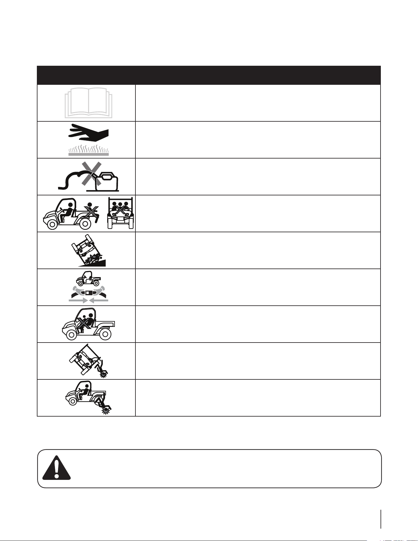
This page depicts and describes safety symbols that may appear on this product. Read, understand, and follow all instructions on the
machine before attempting to assemble and operate.
Symbol Description
READ THE OPERATOR’S MANUAL(S)
Read, understand, and follow all instructions in the manual(s) before attempting to
assemble and operate
WARNING— HOT SURFACE
Hot Surface - Do not touch.
WARNING — GAS CONTAINER
Avoid injury from explosion. Do not place gas container in cargo box when fueling.
WARNING— RIDERS MUST BE IN SEATS
No riders in cargo box or anywhere other than seats.
MAX 15º
WARNING— SLOPES
Do not operate on slopes greater than 15°.
WARNING— SEAT BELTS
Always wear the seat belt when operating the utility vehicle.
WARNING— ONE RIDER PER SEAT
Only one person in each seat.
WARNING— ROLL OVER
Falling off or rollover may cause serious injury or death.
WARNING — RIDERS FALLING
Riders can fall off and be seriously injured or killed.
Controls and Features
3
8
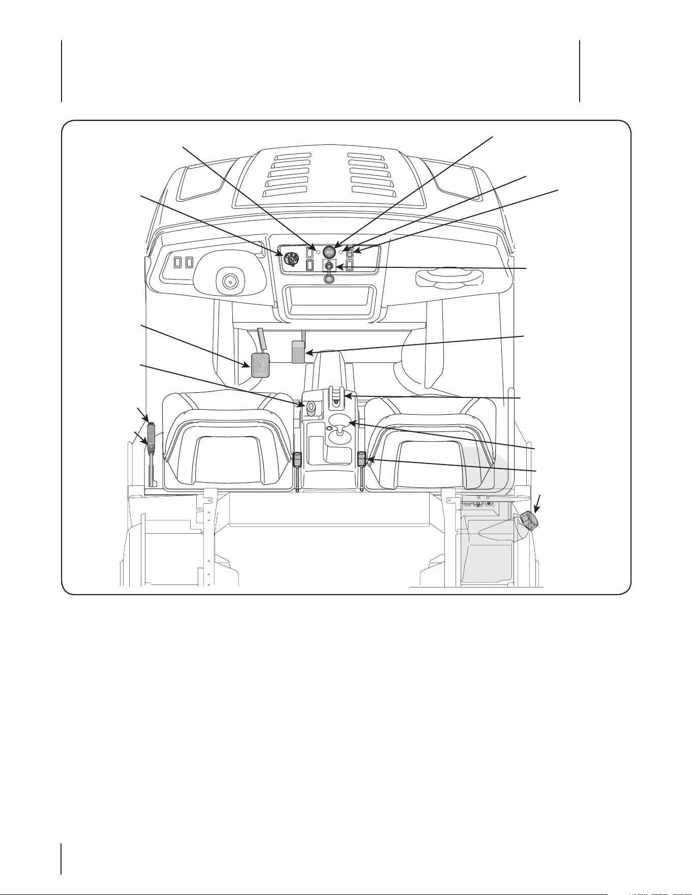
Read this operator’s manual, safety symbols, and operating instructions on the vehicle before operating. Compare the illustrations in
this manual with your unit to familiarize yourself with the location of various controls and adjustments. Reference to the right or left
hand side of unit is observed from the operating position. Save this manual for future reference.
IMPORTANT: Refer to the Engine operator’s manual before operating this vehicle to familiarize yourself with the engine controls and
adjustments.
A
F
G
I
J
K
H
L
M
E
B
N
O
C
D
A 4x4 Switch (all 4X4 units only)
B Ignition Switch
C Brake Pedal
D Differential Lock Lever
E Parking Brake Lever
F Warning Light Cluster
G 12 Volt Power Outlet
H Accelerator Pedal
I Shift Lever
J Cup Holders (if equipped)
K Seat Belts
L Fuel Tank
M Choke Knob (air-cooled, gas units only)
N Check Engine Light (EFI Models Only!)
Glow Plug Light (Diesel Models Only!)
O Enging Over-Temp Light (Liquid Cooled Models Only!)
9Section 3 — controlS and FeatureS
Engine Over-Temp Light
The engine over-temp light (red) is located on the dash panel on
the right side of the warning light cluster. When lit, this indicates
that the engine is running too hot, and MUST be immediately
shut off and allowed to cool.
Ignition Switch
WARNING: Never leave a running machine
unattended. Always set parking brake, stop engine
and remove key to prevent unintended starting.
The ignition switch is located to the right of the steering wheel
on the left side of the dash panel. To start the engine, insert the
key into the ignition switch and turn clockwise to the START
position. Release the key into the Run position once engine has
fired.
Refer to Starting The Engine in the Operation Section of this
manual for detailed starting instructions.
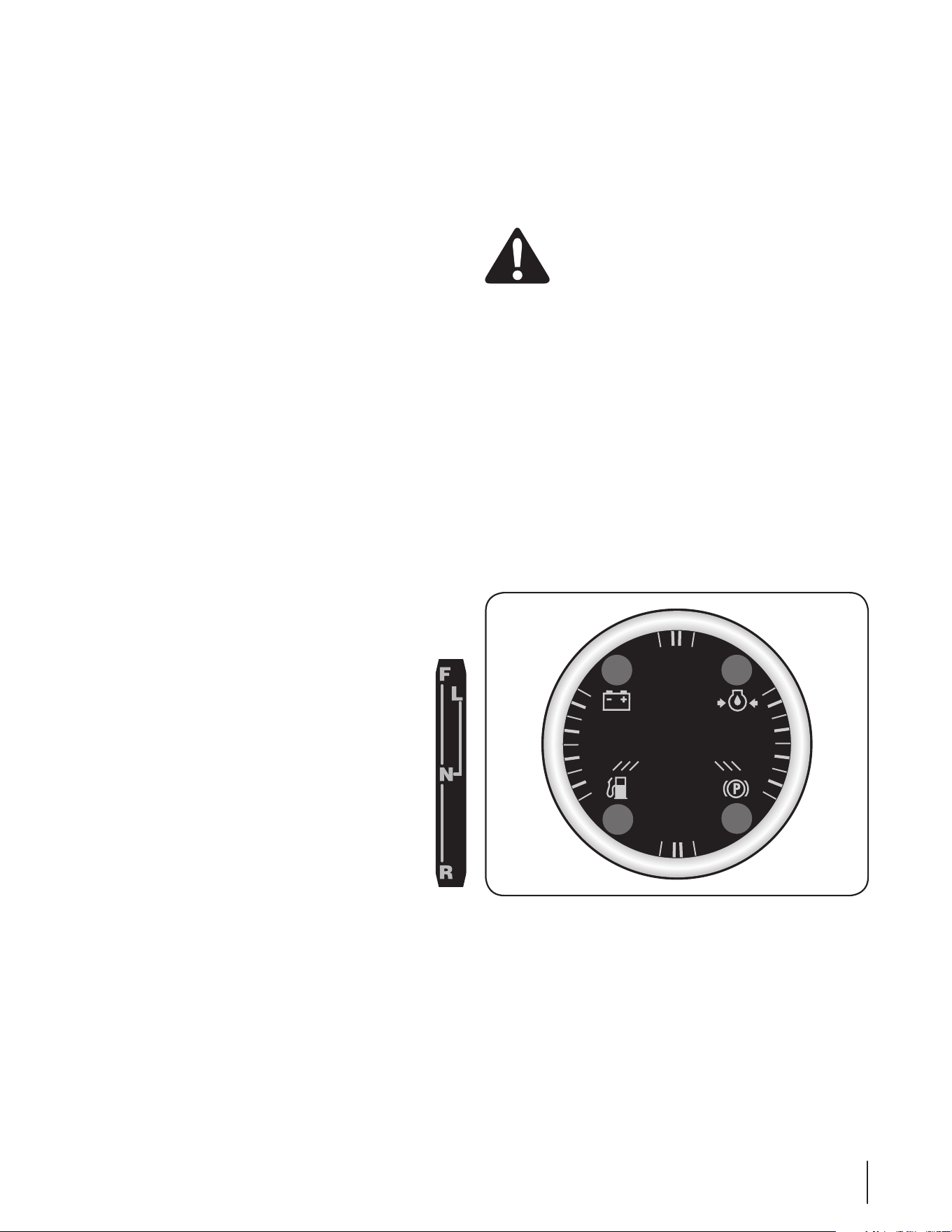
Warning Light Cluster
The warning light cluster is located in the middle of the dash
panel. See Figure 3-1. There are four warning lights: battery,
parking brake light, engine oil pressure light, and low fuel light.
The engine oil pressure light activates when engine has low oil
pressure. The battery light will indicate that the battery is low on
power. The low fuel light activates when fuel is low in the tank.
The parking light indicates that the parking brake is engaged.
HOURS 1/10
FUEL
PARK
BRAKE
OILBATT.
Figure 3-1
Hour Meter
The hour meter is located in the center of the warning light
cluster. It reads the elapsed time key is in the Run or Accy.
position. See Figure 3-1.
NOTE: Every 50 hours a “change oil” message will flash on the
display for 2 minutes every time the UV is started. This message
will repeat for the first two minutes after each 50 hour interval.
The oil pressure indicator light will also flash when this display
is active. Before the interval expires, change the crankcase oil as
instructed in the Engine Manual.
Accelerator Pedal
The accelerator pedal is located on the right side of the floor
beneath the dash panel. Depressing the accelerator pedal will
move the vehicle in the direction selected on the gearshift. As
the pedal is depressed, speed will increase to the maximum
selected range. Releasing the pedal reduces the speed, but does
not stop the vehicle. The brake must be applied to stop vehicle.
Brake Pedal
The brake pedal is located on the left side of the floor beneath
the dash panel. Remove foot from accelerator pedal apply
pressure to the brake pedal evenly until vehicle slows down and
stops.
Parking Brake Lever
The parking lever is located to the left of the driver’s seat. It holds
the brake in the engaged position for parking.
To engage the parking lever, pull up on the parking brake lever,
and parking brake light on dash will come on to indicate parking
brake is engaged.
To release parking brake, push down on brake pedal, depress
button on top of park brake lever, and move lever to off position.
NOTE: The engine will stall when the parking brake is engaged
and the unit is not in Neutral.
Choke Knob (Air-cooled, gas units only!)
The choke knob is located to the left of the driver’s seat. The
choke is used when starting a cold engine. It richens the fuel
mixture for cold weather starting.
Shift Lever
The shift lever is located in the center console between the
seats and has four positions (4x4 only), FORWARD, LOW,
NEUTRAL, and REVERSE (the 4x2 unit has three positions -
FORWARD, NEUTRAL, and REVERSE). The brake pedal must
be depressed and the utility vehicle must not be in motion
when moving the shift lever.
NOTE: To shift into LOW, move the shift lever from the
neutral position towards the passenger seat and then
forward.
IMPORTANT: Never force the shift lever. Doing so
may result in serious damage to the utility vehicle’s
transmission.
Differential Lock Lever
The differential lock lever is located in the center console
between the seats. When engaged, the differential lever locks
the rear differential so both rear wheels will pull equally.
Check Engine Light
The check engine light (green) is located on the dash panel on
the left side of the warning light cluster. When lit, take unit to
your Cub Cadet dealer for a diagnostic test.
10 Section 3— controlS and FeatureS
4x4 Switch (4x4 units Only)
The 4x4 switch is located on the right side of the dash panel.
Push in top/bottom of switch to activate or deactivate 4x4
capability.
12V Power Outlet
The 12V power outlet is located in the center of the dash panel.
It is used for the convenience of plugging in accessories that
require a power source with a maximum load of 5 amps at 12
volts.
Cup Holders
The cup holders are located between the seats. They are
designed for the use of non-alcoholic beverages.
WARNING: Never operate this vehicle while under
the influence of alcohol or drugs. Doing so can result
in serious personal injury or death.
Seats
The driver seat has a tool box underneath it, which can be easily
accessed by lifting the seat. This box may be removed by turning
the two 1/4 turn fasteners securing it to the frame for easy access
to battery, etc.
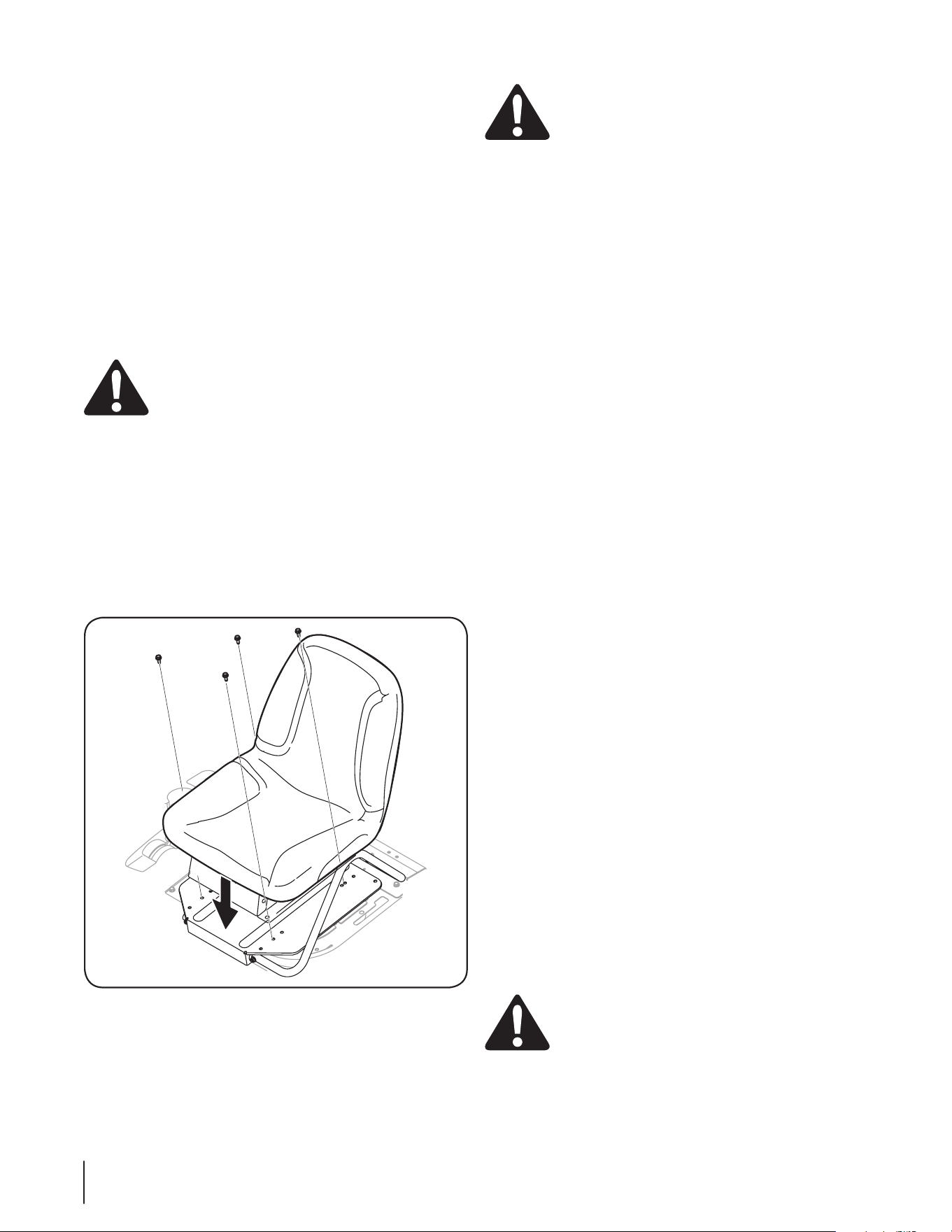
The seats can be adjusted by removing the bolts securing them
to the seat pan. Move the seat to the desired holes in the seat
pan, and reattach the seat using the bolts removed earlier. See
Figure 3-2.
Figure 3-2
Seat Belts
The seat belts are located on either side of the driver and
passenger seats. When used together with the OPS (Rollover
Protective Structure) they are effective in reducing injuries to the
operator in the event of an accidental rollover.
WARNING: Always wear the seat belt when
operating the utility vehicle.
The position of the lap belt portion of the seat belt should be
adjusted for both the operator and the passenger before driving.
Although having the belt at 300 is typical for many people, it will
not accommodate all body sizes and shapes. Make sure the seat
belt is adjusted to the lowest possible lap position before riding.
To adjust the position of the seat belts:
1. Loosen the seat belt mounting bolts.
2. Reposition both the buckle an retractor. Tighten the
mounting bolts.
Cargo Box Electric Lift Switch (Optional)
If equipped, the cargo box electric lift switch is located on the
dash panel. It activates lift to raise and lower cargo box.
Auxiliary Light Switch (Limited Edition Only)
If equipped, the auxiliary light switch is located on the left side
of the dash panel. It turns power on and off for the fog lights and
light bar.
NOTE: If you are running the fog lights in addition to all the other
lights included with the Limited Edition unit, i.e., headlights, light
bar, more than 50% of the time, we recommend you purchase
the Heavy Duty Alternator Kit to prevent excessive drain of the
battery.
Rear Power Outlet Switch (Optional)
If equipped, the rear power outlet switch is located on the dash
panel. It turns power on and off for the rear outlet.
Cargo Box
The cargo box is raised by a gas spring. Manually remove the
contents of the cargo box before lifting the cargo box. Pull up on
the release latch located behind the driver’s seat and lift up the
cargo box. Once the cargo box is in the raised position, access to
the engine is possible. If equipped with a electrical lift, the cargo
box can be raised to dump cargo.
IMPORTANT: Do not exceed the vehicle’s Total Load Capacity
of 1,400 lb., which includes driver, passenger, accessories, and
cargo. Do not exceed 1000 lbs. in the cargo box.
Half Doors
The doors are designed to assist in keeping the operator and
passenger inside the vehicle during operation. Do not operate
vehicle without doors in place.
To open the half doors on the vehicle, pull the handle outward to
release the latch. To close, gently, but firmly, close door.
WARNING: Doors are not to be removed. The only
exception is when installing a hard cab with hard
doors.

Operation
4
11
Filling Fuel Tank
1. Stop vehicle on a level surface and apply parking brake.
2. Turn the ignition key to the STOP position and remove the
key.
3. Allow engine to cool several minutes before you add fuel.
4. Clean area around fuel cap and remove cap.
5. Fill tank with fresh, unleaded, regular grade fuel only to
bottom of filler neck. Use a minimum of 87 octane.
6. After refueling, make sure tank cap is closed securely.
Starting Engine
WARNING: This is an off-road utility vehicle and it
should not be operated on public highways. Know
and comply with all laws and regulations governing
the use of off-highway vehicles in your area.
IMPORTANT: Before starting the engine read this manual and the
Kohler Engine manual thoroughly to understand all instructions.
WARNING: Do not run an engine in an enclosed
area. Move the vehicle to an outside area before
running the engine.
IMPORTANT: Tires are shipped over-inflated. Reduce inflation
pressure in all tires to approximately 14-18 psi.
1. Sit in the operator’s seat and place key switch in STOP
position.
2. Put into Neutral.
3. Lock parking brake.
NOTE: Engine will stop when the parking brake is engaged
and the unit is not in Neutral.
4. On air-cooled, gas powered units, pull out the choke knob
if engine is cold.
On diesel units only, turn the ignition key clockwise to
the “RUN-PREHEAT” position, and observe the glow plug
indicator light on the instrument panel. Wait until the glow
plug indicator light turns off before cranking the engine.
NOTE: Preheating may not be necessary if the engine has
been running and is warm.
5. Turn key to the START position.
6. Release key to the RUN position when engine starts.
7. If engine does not start, wait a few seconds and repeat
procedures.
8. After engine starts, push in choke knob.
9. Release parking brake.
IMPORTANT: DO NOT run the starter continuously for
more than 5 seconds, otherwise the battery may discharge
quickly.
NOTE: On air-cooled, gas powered models, if the engine
surges after starting while idling or driving at a low speed,
apply choke as needed until engine has warmed up.
IMPORTANT: Do not operate the engine under full load
until engine has warmed up.
Stopping Engine
1. To stop utility vehicle, release accelerator pedal and
depress brake pedal until vehicle comes to a complete
stop.
2. Move shifter back into Neutral.
3. Set parking brake and turn key switch to STOP position.
4. Remove the key when not in use.
WARNING: The vehicle will roll if the parking brake
is not engaged and locked.
Safety Interlock System
To verify the operation of the shift interlock:
1. Set the parking brake.
2. Place the shift lever into neutral position and start the
engine.
3. Keep your foot on the brake pedal during this process.
4. Move the shift lever to the forward position, the engine
should shut off.
5. Repeat steps 1 through 3, with the but shift lever in reverse.
The engine should shut off.
Driving Utility Vehicle
1. Adjust the operator’s seat (bucket seat models only) to the
most comfortable position that allows you to operate all
controls and pedals. See Seat Adjustment in the Controls &
Features section.
2. Adjust the seat belt to fit snugly but comfortably around
your lap, then buckle the seat belt.
WARNING: DO NOT operate the vehicle without
the OPS and seatbelt.
3. Make sure front wheels are turned to the desired direction.
4. Pull up the parking brake lever to release parking brake.
5. Move the shift lever in the center console to the desired
setting. To avoid damaging transmission, depress brake
pedal fully and make sure vehicle is completely stopped
before shifting into Forward, LOW, or Reverse.
NOTE: Use the Forward range when travelling on level and
stable surfaces. Use the LOW Forward range when climbing
or descending slopes or on unstable surfaces.

12 Section 4— operation
WARNING: Do not stop or start suddenly when
going uphill or downhill. Be especially cautious
when changing direction on slopes. Apply brakes
when going down slopes to maintain control of
vehicle.
6. Release brake pedal and apply pressure to the accelerator
pedal.
7. Release accelerator and apply brake pedal evenly and
firmly to slow down or stop.
Engaging 4x4 (If Equipped)
The 4x4 switch is located on the right side of the dash panel. See
the Controls & Features section.
1. To engage, stop or slow vehicle speed and push up on the
switch. All four wheels will now continue to have power.
IMPORTANT: Engage the 4x4 feature as the first option
when stuck in mud or similar situation where two wheel
drive is ineffective at moving vehicle.
2. If still unable to move vehicle with the 4x4 engaged,
disengage 4x4 by pushing down on the switch and
engaging the differential lock as described below.
Engaging Differential Lock
The differential lock lever is located in the center console
between the seats (bucket seat models only). See Know Your
Utility Vehicle.
1. To engage, stop vehicle, place into Neutral, and pull the
lever rearward. The differential will then lock and remain so
until it is disengaged, giving continuous power to both rear
wheels.
IMPORTANT: Engage the differential as the last option when
stuck in mud or similar situation or when the left and right side
wheels are turning at slightly different speeds.
WARNING: To avoid transmission damage, injury,
or turf damage, go slow when operating vehicle
with differential lock engaged as steering response
is noticeably reduced. Also, do not drive the unit
with the differential lock engaged on concrete,
asphalt or any high traction surfaces.
Disengaging Differential Lock
1. To disengage the differential lock, stop the unit, place in
Neutral, and push the lever forward.
Raising & Lowering Cargo Box
WARNING: To prevent the possibility of bodily
injury from unintentional lowering of the cargo box,
be sure vehicle is on a level and stable surface and
parking brake is locked before raising cargo box.
Manual Lift
1. Park the vehicle safely on level ground and set parking
brake.
2. Empty cargo by hand and unlatch cargo box by pulling up
on the cargo latch.
3. While holding the latch up, lift the cargo box.
4. Lower and allow bed to re-latch cargo box before
operating unit.
Electric Lift (Optional)
1. Park the vehicle safely and turn key to the RUN position.
2. Raise cargo box by pressing and holding top of electric lift
switch. Release switch when box is at desired dump height
or when maximum height is reached.
NOTE: A ratcheting noise will indicate cargo box is at full
extension. The same noise will also be heard when cargo
box is at the full down position. If lift capacity of the power
lift is exceeded, a ratcheting will also be heard.
3. To lower cargo box, push on bottom of electric lift switch.
Turn ignition switch to the STOP position.
Dumping Load From Cargo Box
1. Back up the vehicle to the dump site and apply parking
brake.
2. Unlatch the tailgate from cargo box.
3. If using an electric lift, raise cargo box to dump load and
lower box when empty.
WARNING: The center of gravity changes as a
loaded cargo box is raised. Do not allow rear wheel
to hang over the edge of a loading dock or ravine.
The cargo box weight may shift over center and
vehicle could tip over backwards.
WARNING: A loaded cargo box can be very heavy.
Do not attempt to dump a loaded cargo box unless
vehicle is equipped with an electric lift option.
IMPORTANT: If dumping by electric lift, stop immediately if
actuator clutch slippage occurs. Lower cargo box completely and
remove excess load by hand before dumping.
4. Reconnect the tailgate to the cargo box. Do not drive the
vehicle with cargo box in the raised position.
Loading the Cargo Box
WARNING: The utility vehicle may become
unstable if the cargo box is loaded incorrectly. Avoid
loose and shifting loads or uneven loading of
material.
1. Verify cargo box is latched before loading.
2. Securely anchor all loads in cargo box and do not load
beyond maximum capacity.
3. The maximum box capacity is 1000 lbs. (362.9 kg).
4. When loading objects into vehicle, be sure load is securely
anchored and evenly distributed in cargo box.

13Section 4 — operation
5. Do not load above height of cargo box front panel. Load
could shift forward striking driver or passenger or cause
driver to loose control of vehicle.
6. Avoid loads which exceed physical dimensions of cargo
box.
7. Avoid concentrated loads at rear or side of cargo box. Be
sure load is distributed evenly.
8. Reduce load and ground speed when operating over rough
or hilly terrain. DO NOT overload vehicle. Limit loads to
those that can be safely controlled.
Towing Loads
WARNING: To help prevent personal injury due to
loss of control or tipping, always tow a load slow
enough to maintain control.
1. Do not tow a load that exceeds 1,400 lbs. rolling weight (i.e.
trailer plus cargo) and never exceed 140 lbs. tongue weight.
2. Go slow when towing a heavy load. Allow for increased
braking distance. Tow load at a speed slow enough to
maintain control.
3. Do not tow on slopes greater than 5°.
4. Be particularly cautious when towing down even a gradual
slope or turning. The extra weight tends to push the tow
vehicle and may cause you to lose control (braking and
steering ability are reduced; towed equipment may jack-
knife).
IMPORTANT: Extreme angles such as high railroad
crossings can place high bending loads on hitch
connection. If traversing terrain where these conditions
exist, use of a ball or pintle type hitch is recommended.
5. Always use approved hitch and hitch point provided for the
utility vehicle. Do not modify the hitch in any way.
Transporting Vehicle
IMPORTANT: Never tow the vehicle. Transmission damage will
occur if vehicle is towed. Haul the vehicle on a heavy-duty trailer
or on a full-size truck.
1. Once the utility vehicle is loaded onto the trailer or truck,
leave transaxle gearshift lever in forward or reverse.
2. Apply parking brake during transport.
3. Fasten vehicle to trailer or truck with straps, chains, or
cables.
Operator Protective Structure (OPS)
This utility vehicle is equipped with a Operator Protection
Structure (OPS) and seat belts. When used together they are
effective in reducing crushing injuries to the operator in the
event of an accidental rollover or tip-over. The safety provided by
the OPS is minimized if the seat belt is not properly adjusted AND
buckled.
WARNING: Always wear the seat belt when
operating the utility vehicle.
Use the following guidelines when using a utility vehicle
equipped with a OPS:
1. Be aware of overhead clearances in the area of operation.
Check for clearance of door (or gate) openings and other
overhead objects such as utility lines and tree branches.
Overhead objects could catch the OPS and upset the utility
vehicle.
2. Do not modify the OPS by drilling holes for, or welding
accessories to the structure.
3. Do not use the OPS to pull objects with the utility vehicle.
Use ONLY the utility vehicle hitch for pulling.
4. In the event of an accident, have the OPS carefully
inspected and, if necessary, replaced by your Cub Cadet
dealer. Do not attempt to repair the OPS.
Maintenance & Adjustments
5
14
Engine Coolant
Checking Engine Coolant Level (EFI & Diesel Powered Units Only!)
Before each use, the engine coolant level in the overflow
reservoir should be checked to ensure it is within the operating
range. Engine coolant absorbs heat from the engine and
transfers the heat to the air flowing through the radiator. If the
coolant level becomes low, the engine may overheat and could
cause severe damage to the engine.
Use a permanent type antifreeze containing corrosion and rust
inhibitors. Dilute the antifreeze with water at a 1 : 1 ratio to mix
the coolant solution (50% antifreeze : 50% water).
NOTE: Distilled water is recommended for the coolant solution
IF your tap water has a high mineral content. Minerals cause
scaling in the engine and the radiator coolant passages. System
efficiency will be greatly reduced over time and severe engine
damage may result. Refer to the antifreeze manufacturer’s
instructions for additional information on dilution procedures.
1. Check the coolant level when the engine is cold and the
utility vehicle is on a level surface.
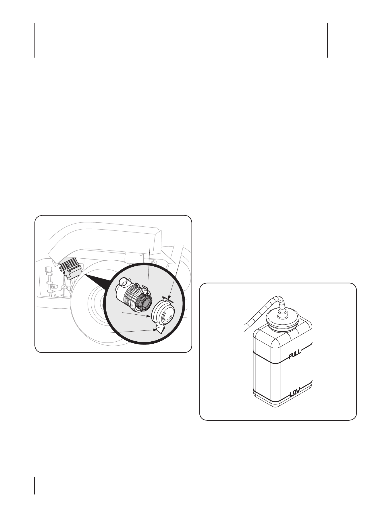
2. Raise the hood and check the coolant level in the overflow
reservoir on the right side of the radiator.
3. If the coolant level is below the “LOW” mark, remove the
cap from the reservoir and add coolant solution to the
“FULL” mark. Refer to Figure 5-2.
NOTE: The cooling system is a closed type. Normally, to prevent
air from entering the system, the radiator cap should not be
removed.
Figure 5-2
If the overflow reservoir is empty, the radiator cap should be
removed and the coolant level in the radiator checked before
adding coolant to the reservoir. If necessary, first refill the system
through the radiator filler neck as follows:
Engine
Air Filter (Air-Cooled, Gas Powered Units Only!)
The engine air filter should be changed every 50 hours. Change
more frequently if operated in extremely dusty conditions.
1. The air filter is located on top of the engine. To access,
simply remove wing nut securing plastic cover, remove
wing nut securing filter, inspect and replace if excessively
dirty or damaged. See your Kohler engine manual for more
detailed instructions.
2. Reattach cover and secure with latch.
Read the Kohler engine operator’s manual for any other service
or maintenance information pertaining to the engine.
Air Filter (EFI & Diesel Powered Units Only!)
The engine air filter should be changed every 50 hours. Change
more frequently if operated in extremely dusty conditions.
3. Pull up on latch and turn counter-clockwise to release air
cleaner cover. See Figure 5-1.
Cover
Dust
Valve
Element
Latch
Figure 5-1
4. Remove cover. Remove and inspect air cleaner element. If
excessively dirty or damaged, replace element.
5. Reattach cover and secure with latch.
IMPORTANT: When reattaching cover, make certain that
dust valve is pointing downward. See Figure 5-1 inset.
Read the Kohler engine operator’s manual for any service or
maintenance information pertaining to the engine.
15Section 5 — Maintenance & adjuStMentS
WARNING: It is dangerous to remove the radiator
cap when the system is hot. Allow the system to cool
before removing the radiator cap.
1. Turn the radiator cap counterclockwise to the first stop to
release any pressure.
2. Push downward on the cap and turn counter-clockwise
until the cap stops then lift cap off.
3. Slowly pour coolant into the filler neck until the level
reaches the bottom of the filler neck overflow flange.
4. Wait a few minutes to allow as much air as possible to
escape through the filler neck, then reinstall the radiator
cap.
5. Fill the overflow reservoir to the “FULL” mark.
6. Start the engine and allow it to run for a short period. Stop
the engine.
7. Recheck the coolant level in the overflow reservoir and
refill as needed. Reinstall the reservoir cap.
8. If engine over-temp light comes on or stays on after filling
radiator and reservoir, see your Cub Cadet service dealer to
bleed air from system.
Changing the Engine Coolant (EFI & Diesel Powered Units Only!)
The engine coolant should be drained and replaced with new
coolant solution every 2 years or 500 hours. See your Cub Cadet
service dealer to have the engine coolant changed.
Cooling System Hoses (EFI & Diesel Powered Units Only!)
Check the cooling system hoses and water pump belt for any
cracks or deterioration after every 100 hours of operation. Check
for loose hose connections. Replace any damaged hoses and
tighten any loose connections. Replace a worn or damaged
water pump belt.
Servicing the Fuel Filter (Diesel Models Only)
WARNING: Do not service the fuel filter when
tractor is hot or near any source of ignition. Allow
the tractor to cool.
The utility vehicle is equipped with an in-line fuel filter and water
separator located on the right side of the vehicle underneath the
passenger seat.
WARNING: Diesel fuel is a toxic substance. Dispose
of in an environmentally safe manner. Contact your
area EPA office for proper disposal methods and
recycling center locations.
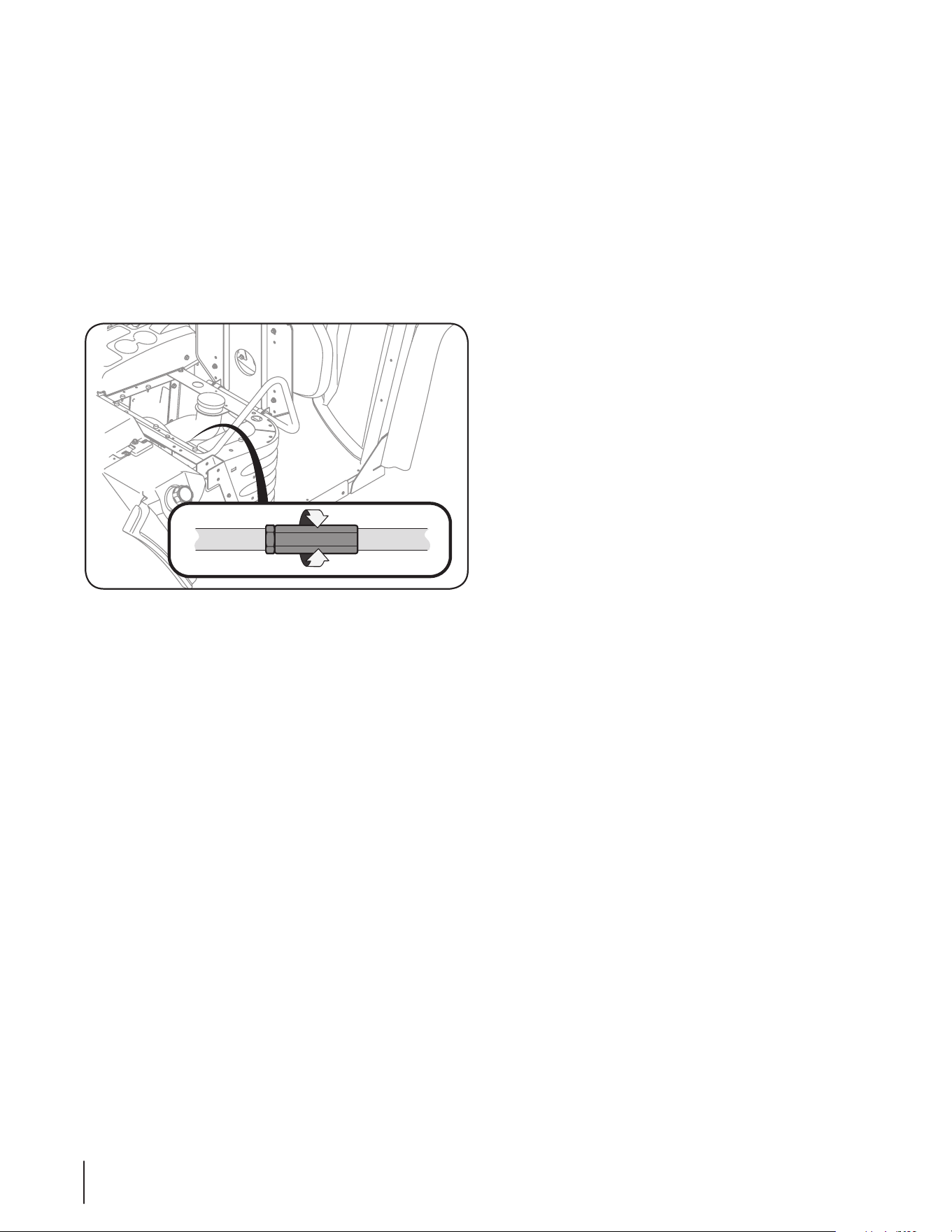
Draining The Fuel Filter
The fuel filter is equipped with a valve to drain condensate
(water) that has separated from the diesel fuel and settled at the
bottom of the filter.
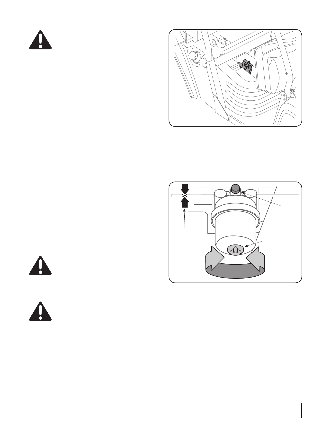
Drain the condensate from the fuel filter before each use. You
can access the fuel filter beneath the passenger seat. Refer to
Figure 5-3.
Figure 5-3
1. Stop the engine and raise the passenger seat by removing
the wing nut securing it to the frame.
2. Place a suitable container beneath the filter drain valve.
3. Turn the filter drain counterclockwise to open. Allow the
water at the bottom of the filter to drain until only pure
diesel fuel drains from the valve. See Figure 5-4.
Air
Bleed
Knob
Fuel
Filter
Drain
Clamp
Fuel
Line
Figure 5-4
4. Turn the filter drain clockwise to close.
5. Slowly turn the air bleed knob counterclockwise until fuel
begins to seeps out around the bleed knob. Turn air bleed
knob clockwise to close. Refer to Figure 5-4.
16 Section 5— Maintenance & adjuStMentS
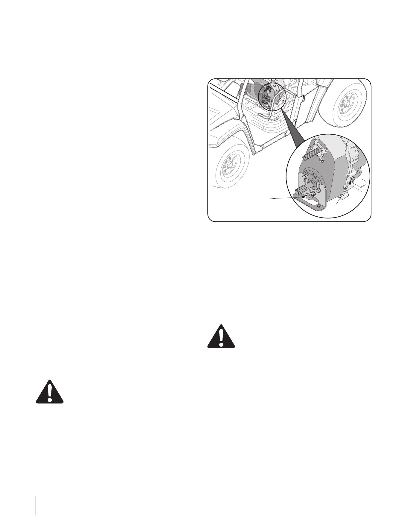
2. Allow transmission sufficient time to cool before
attempting any maintenance or repairs.
3. Raise and secure cargo box, if manual lift.
4. Access drain plug through slot on underside of machine
and remove plug. See Figure 5-3.
Fill/
Level
Plug
Drain
Plug
Figure 5-5
5. Allow oil to drain into a suitable container.
6. Check O-ring on drain plug and replace if missing or in
poor condition.
7. Add approximately 64 oz of Shell Spirax 80W-90 GL5 oil
through the fill/level plug port. When oil begins coming
out of opening, the transmission is full.
8. Install and tighten fill/level plug.
9. Lower and latch cargo box.
Differential Case Oil (Rear)
WARNING: The fluid for the differential has been
specially formulated to ensure the safe and proper
operation of your vehicle. When changing the
differential oil replace it with part no. 737-04158 –
Shell Spirax 80W-90 GL5. Failure to use Shell Spirax
80W-90 GL5 may result in a failure of the drive
system which could result in property damage or
personal injury. DO NOT substitute.
Check the differential case oil every 100 hours or yearly and
change it at the first 50 hours and then again at 500 hours.
1. Park vehicle on level surface, place shift lever in Neutral,
and apply parking brake.
2. Allow the unit sufficient time to cool before attempting any
maintenance or repairs.
3. Locate the differential below the cargo box in the rear of
the vehicle.
4. Locate the Oil fill/Level plug, refer to Figure 5-6. Remove
the plug, and oil should begin to seep out. If no oil seeps
out, slowly add oil through the oil Fill/level port until oil
begins to seep through the oil fill/level plug port.
Changing The Fuel Filter
Replace the fuel filter cartridge after every 500 hours of
operation.
NOTE: There is no shut off valve in the fuel system. To stop the
flow of fuel while replacing the filter, it will be necessary to
carefully clamp the fuel line between the fuel tank and the filter.
1. Place a suitable container beneath the filter drain.
2. Clamp the fuel line just to the rear of the fuel filter. See
Figure 5-4.
3. Open the filter drain and drain the filter into the container
below. Close the filter drain.
4. Turn the filter approximately 1/4 turn counter-clockwise (as
viewed from bottom) to align the unlock icons.
5. Pull the filter cartridge straight downward to remove from
the filter body.
6. Align the unlock icons of the new filter cartridge and filter
body, and push the new filter cartridge fully up into the
filter body.
7. Turn the new filter cartridge approximately 1/4 turn
clockwise to lock.
NOTE: The lock icons on the body and cartridge should be
aligned or nearly aligned.
8. Remove the clamp from the fuel line. The filter should
begin to fill will diesel fuel.
9. Slowly turn the air bleed knob counterclockwise until fuel
begins to seep out around the bleed knob. Turn the air
bleed knob clockwise to close.
10. Remove the catch container and properly dispose of the
diesel fuel.
11. Start and run the utility vehicle’s engine for a short period
to fully bleed any residual air from the filter, fuel lines, and
injection pump.
Engine Breather Service (Diesel Models Only)
The engine breather should be changed after every 2000 hours
of engine operation. Contact your Cub Cadet dealer.
Fuel Injector Nozzle Service (Diesel Models Only)
The fuel injector nozzles should be checked and serviced after
every 2000 hours of engine operation. Contact your Cub dealer.
Transfer Case Oil (All Models)
WARNING: The fluid for your transmission has
been specially formulated to ensure the safe and
proper operation of your vehicle. When changing
the transmission fluid replace it with Shell Spirax
80W-90 GL5. Failure to use Shell Spirax 80W-90 GL5
oil may result in a failure of the drive system which
could result in property damage or personal injury.
DO NOT substitute.
Check the transfer case oil every 100 hours or yearly and change
it at the first 50 hours and then again at 500 hours.
1. Park vehicle on level surface, place shift lever in Neutral,
and apply parking brake.
15Section 5 — Maintenance & adjuStMentS
Note: This unit also has an oil fill/level plug on the front
side of the differential as well. Use this plug when checking
the differential oil on units with an electric bedlift.
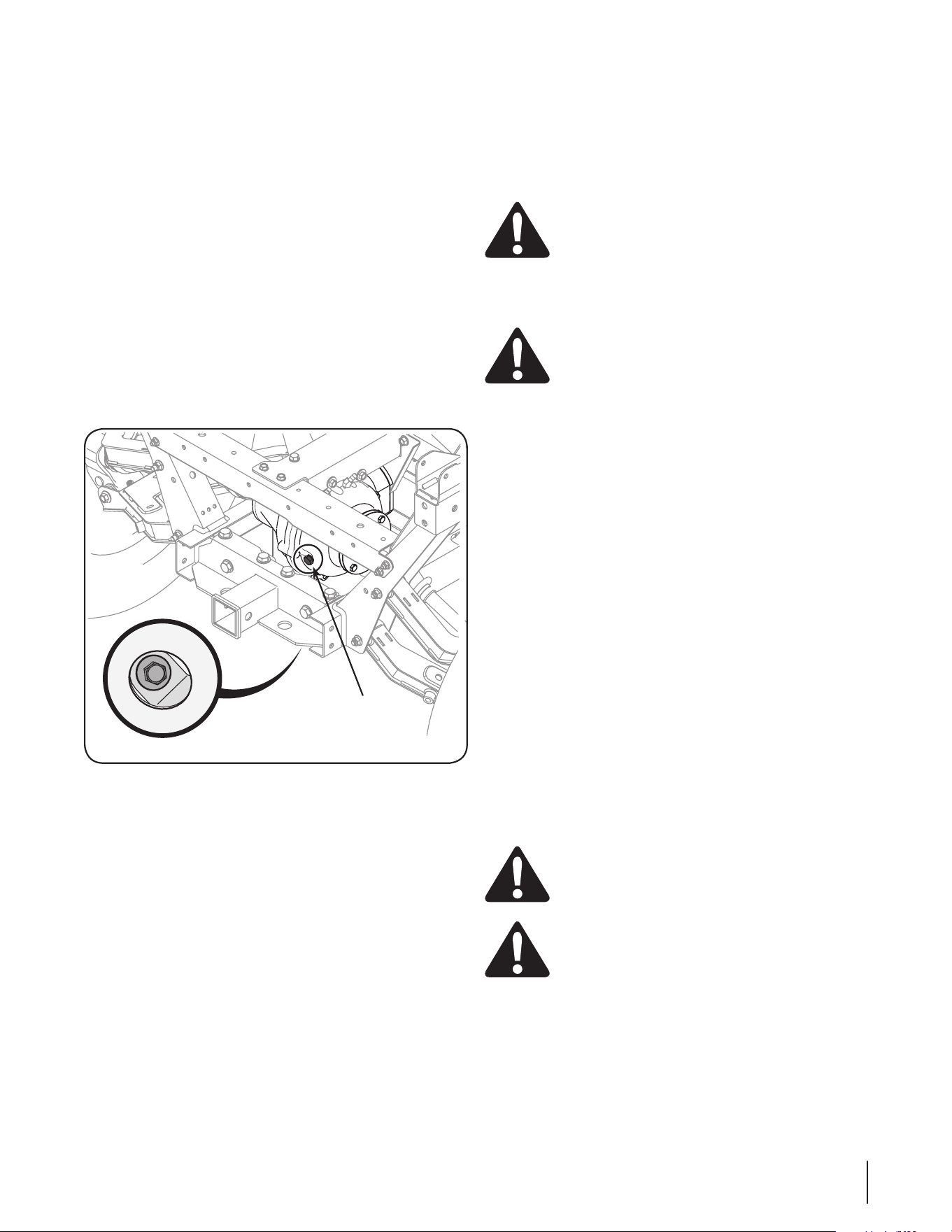
Changing the Differential Case Oil
1. Locate the drain plug on the bottom, front side of the
differential, through a cut-out in the skid plate. Remove the
drain plug. See Figure 5-6.
2. Allow oil to drain into a suitable container.
3. Check O-ring on drain plug and replace if missing or in
poor condition. Reinstall the drain plug and tighten.
4. Add approximately 22 ounces dry (dry – a fluid change
may require less). Or refill to bottom of either front or rear
level check plug. Use 737-04158 Shell Spirax 80W-90 GL5.
Oil through the fill/level plug port. When oil begins coming
out of one of the two oil fill/level plug ports, the differential
is full.
5. Install and tighten the fill/level plug(s).
Oil fill/Level Plug
Drain Plug
Figure 5-6
CFD (Centralized Front Drive)
Change the oil in front CFD (centralized front drive) every 100 hrs.
Use only 10w Hy-tran or 10w-40 hy-tran oil (6 oz.) Cub Cadet part
no. 737-3120.
Changing the CFD Oil
1. Remove the oil drain plug located on the bottom of the
gearcase using a 5/16” hex key wrench.
2. Let all of the oil drain out of the unit. Catch an ddiscared
the oil properly.
3. Be sure to clean off any debris on the drain plug and
reinstall. Torque the oil drain plug to 10 ft/pds.
4. Remove the oil fill plug using a 5/16” hex key wrench.
5. Add 180 ml. (6 oz.) of 10w Hy-tran or 10w-40 hy-tran oil (6
oz.) part no. 737-3120.
Note: do not use any other type of oil in theis system or the
four wheel drive will not operate properly!)
6. Reassemble the oil fill plug into the gearcase and torque to
10 ft/pds.
Battery
WARNING: The battery produces a flammable and
explosive gas. Do not smoke near battery. Wear eye
protection and gloves when handling the battery.
Do not allow direct metal contact across battery
posts. The battery is sealed and is maintenance free.
Acid levels cannot be checked and fluid can not be
added.
WARNING: California Proposition 65 Warning:
Battery posts, terminals, and related accessories
contain lead and lead compounds, chemicals known
to the State of California to cause cancer and
reproductive harm. Wash hands after handling.
IMPORTANT: If removing the battery for any reason,
disconnect the NEGATIVE (Black) wire from it’s terminal
first, followed by the POSITIVE (Red) wire. When re-
installing the battery, always connect the POSITIVE (Red)
wire to its terminal first, followed by the NEGATIVE (Black)
wire. Be certain that the wires are connected to the correct
terminals; reversing them could change the polarity and
cause damage to your engine’s alternating system.
Cleaning Battery and Terminals
1. Remove battery from vehicle. Always remove negative
cable first when disconnecting.
2. Wash battery with solution of four tablespoons of baking
soda to one gallon of water.
3. Rinse the battery with plain water and dry.
4. Clean terminals and battery cable ends with wire brush
until bright.
5. Apply petroleum jelly or silicone spray to terminals to
prevent corrosion.
6. Install battery. Always install negative cable last when
connecting.
Jumping Battery
WARNING: Do not attempt to jump start a frozen
battery. Warm to 60 degrees F (16 degrees C). Do not
smoke near battery and wear eye protection and
gloves when handling battery.
WARNING: ON EFI UNITS ONLY, do not attempt
to jump start the battery. Engine damage will occur
to the fuel injection computer.
18 Section 5— Maintenance & adjuStMentS
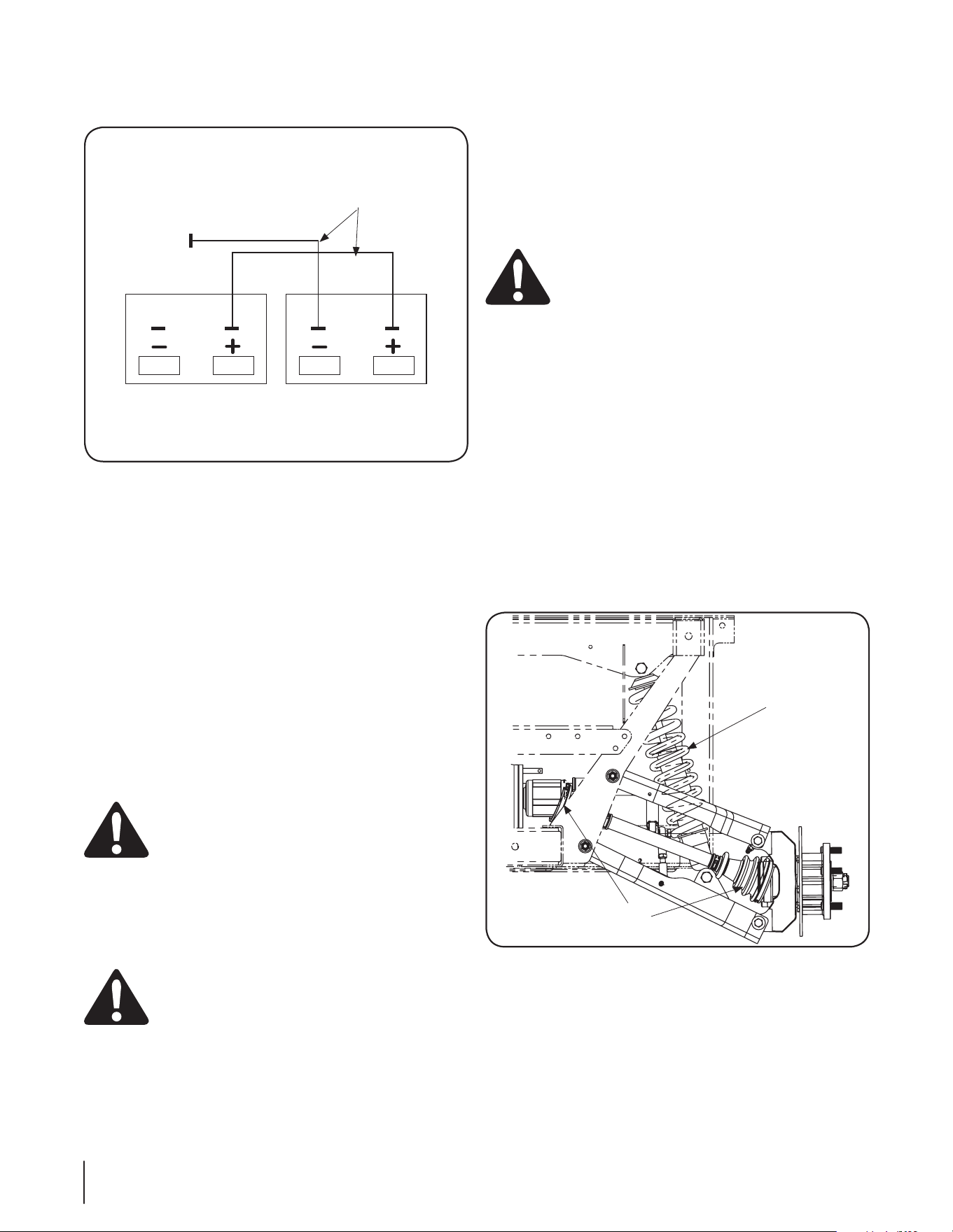
1. Connect positive (+) jumper cable to booster battery
positive (+) post (A). See Figure 5-7.
Jumper Cables
Booster BatteryDisabled Battery
D
C
B
A
Figure 5-7
2. Connect the other end of positive (+) jumper cable to the
disabled vehicle battery positive (+) post (B).
3. Connect negative (-) jumper cable to booster battery
negative (-) post (C).
4. Connect the other end (D) of negative (-) jumper cable to
a metal part of the disabled machine frame away from
battery.
5. Start the engine of the disabled machine and run machine
for several minutes.
6. Carefully disconnect the jumper cables in the exact reverse
order: negative cable first and then the positive cable.
IMPORTANT: Alternator will not charge unless battery has
minimum of 11 volts. Unit will not run if battery voltage is
below 11.
Charging Battery
WARNING: Charge battery in a well ventilated area
and keep away from an open flame or pilot light as
on a water heater, space heater, furnace, clothes
dryer or other gas appliances.
If the vehicle has not been put into use for an extended period of
time, charge the battery with an automotive type 12-volt charger
for a minimum of one hour at six amps.
Tire Pressure
WARNING: Explosive separation of tire and rim
parts is possible when they are serviced incorrectly.
Do not stand in front or over tire assembly when
inflating.
The recommended operating tire pressure is approximately
14-18 psi for all tires. Overinflating above recommended tire
pressure can reduce the life of the tire. Check tire pressure before
driving the vehicle.
Operator Protective Structure (OPS)
Periodically (at least every six months) visually inspect the OPS
and seat belts need to be inspected for damage and proper
function before each use or daily. Replace belt assembly if any
damaged is found.for damage and loose fasteners. If damage is
noted, contact your Cub Cadet dealer.
If an accident has occurred which may have damaged the OPS,
have the OPS thoroughly inspected by your Cub Cadet dealer.
WARNING: To ensure the structural integrity of the
OPS to provide operator protection, do not attempt
to straighten or weld the OPS. A damaged OPS
should be replaced.
If the OPS is removed for any reason, make sure the proper
hardware is used to reinstall it, and that the recommended
torque values are applied to the fasteners.
If you are not installing new bolts when replacing or reinstalling
the OPS, apply Loctite ® 242 to the threads of the bolts that were
removed. Torque the bolts to 50 to 55 ft. lbs.
Front and Rear Shocks
Inspect the front and rear shocks every 100 hours or once a year
for oil leakage. See Figure 5-8. If excessive oil leakage appears,
have shocks repaired or replaced by your local Cub Cadet dealer.
CV Boots
Inspect CV boots (two on each CV axle, eight total) for tears every
50 hours. See Figure 5-8. If tears or excessive wear appear, have
boots replaced by your local Cub Cadet dealer.
Shock
CV
Boots
Figure 5-8
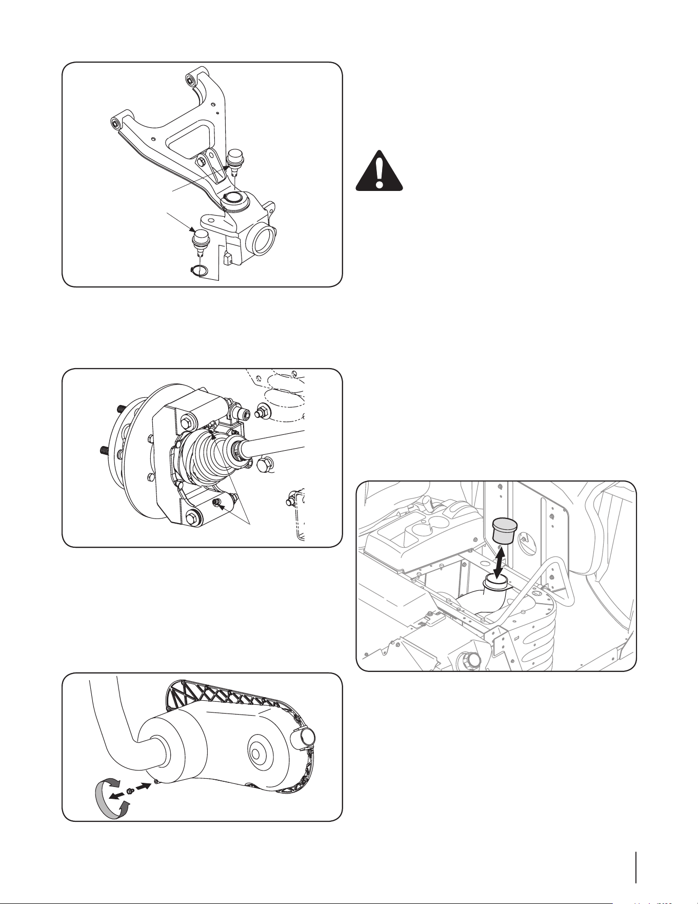
Ball Joints
Inspect the upper and lower front A-arm ball joints on each side
of the vehicle and the two tie rod ends for wear every 100 hours
or once a year. See Figure 5-9. If excessive wear appears, have ball
joints or tie rod ends replaced by your local Cub Cadet dealer.
15Section 5 — Maintenance & adjuStMentS
Ball Joints
Figure 5-9
Rear Knuckles
Lubricate two grease fittings on each axle with 2 or 3 shots of
grease every 50 hours or after each use if consistently running
unit in water deeper than axle. See Figure 5-10.
Lube
Figure 5-10
Draining CVT Cover
Drain CVT cover every 50 hours or after driving vehicle through
more than 12” of water.
1. Remove CVT cover drain plug. See Figure 5-11.
2. Allow water to completely drain out.
3. Reinstall drain plug, and tighten securely.
Figure 5-11
Cleaning
The body panels are scratch and impact resistant automotive
quality ABS plastic. The use of standard car wash soap and
non-abrasive car wax is acceptable for cleaning the body panels.
Avoid any abrasive cleaner or rubbing compounds for these will
damage the body panels. Dry thoroughly to avoid water spots.
WARNING: DO NOT use a pressure washer.
Damage may occur if direct hose spray comes in
contact with intake openings, or any other electrical
components, i.e. at instrument cluster or under dash.
CVT Inlet Filter
A CVT Inlet Filter, 751-12642, is installed in the inlet pipe of the
CVT located under the passenger seat. This filter will prevent
large objects from entering the CVT inlet tube and causing
damage to the fan blades, clutch, belt etc. It is necessary to clean
this filter after ever 20 hours of use or more often under dusty
conditions.
To Clean the CVT inlet filter, follow these steps:
1. Pivot the passenger seat forward to gain access to the CVT
inlet filter.
2. Simply pull the filter out of the CVT inlet tube, shown in
Figure 5-12, and wash with soapy water.
3. Fully rinse the filter and allow it to dry completely, either
on its own, or by flattening it between two paper towels,
or blowing it out gently with compressed air. Reinstall filter
into the CVT inlet tube. Never wring the filter out to dry!
IMPORTANT: Do not use any filter oil on the CVT inlet fliter.
Only wash with soapy water, rinse, dry and reinstall. Replace the
filter when it becomes worn or damaged.
Figure 5-12
20 Section 5— Maintenance & adjuStMentS
Adjusting the Throttle Cable
(Gas Powered Units Only!)
An adjustment is provided in the throttle cable, should such an
action ever be necessary. To locate the cable adjustment, pivot
the passenger seat forward and locate the adjustment in the
throttle cable running along the right side of the unit below the
passenger seat. See Figure 5-13.
1. Loosen the locking nut and thread the adjustment nut
inward or outward in order to maintain at minimum 1/16
of an inch play in the cable when the pedal is in a fully
released (idle) position.
2. Once adjustment is complete retighten jam nut.
Figure 5-13
Service
6
21
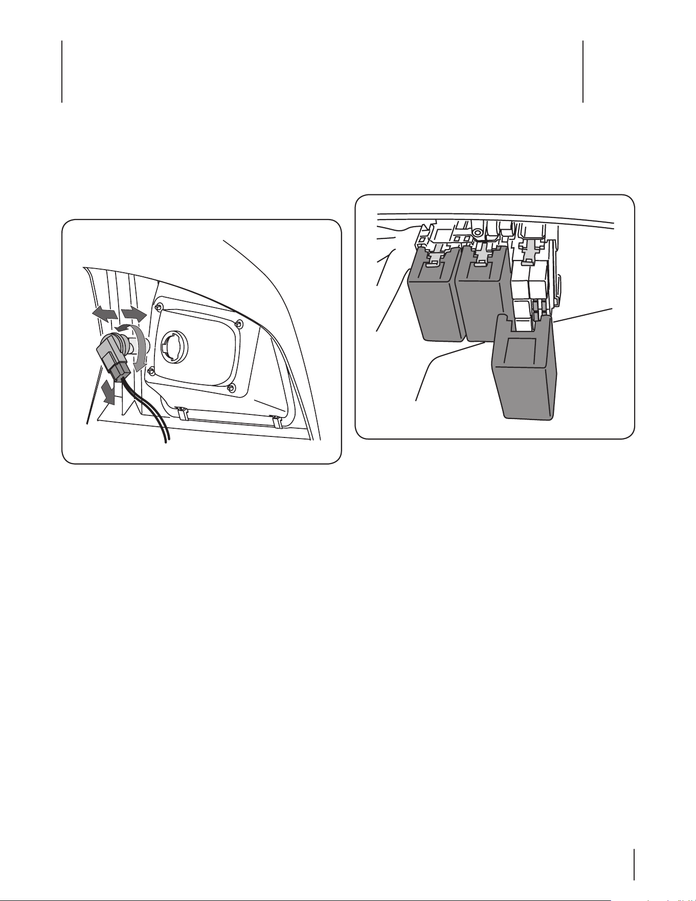
Fuses
1. Unlatch and lift hood forward to get access to under the
dash panel.
2. Remove fuse holder cover. See Figure 6-17.
Figure 6-17
3. Remove the appropriate electrical fuse and replace with
proper amperage fuse.
4. Lower and secure hood.
Headlight Bulbs
1. Raise hood to get access to the headlight assembly.
2. Turn the bulb/socket assembly approximately a quarter
turn counterclockwise to align its tabs with the notches of
the reflector, then remove from the reflector. See Figure
6-16.
Figure 6-16
3. Unplug the wire harness from the bulb/socket assembly.
4. Plug the new bulb/socket assembly into the wire harness.
5. Align the tabs of the new bulb/socket assembly with the
notches of the reflector and insert the bulb. Turn the bulb/
socket assembly clockwise to lock in place.
6. Lower and secure hood.
22 Section 6— Service
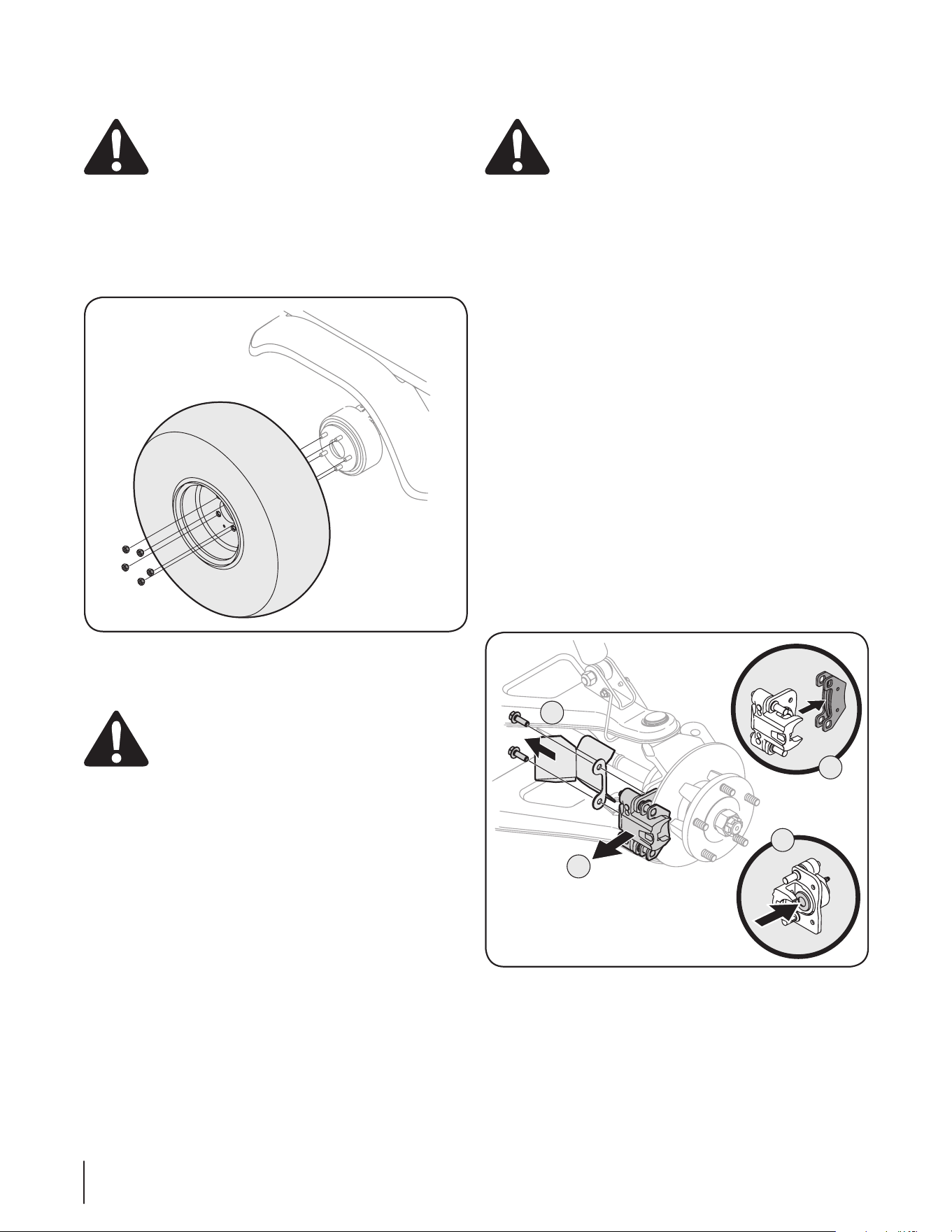
Wheels
WARNING: Using an unstable lifting device and
vehicle support may result in bodily injury. Use a
safe lifting device and supports to work on raised
vehicle.
1. Stop the vehicle on a level surface and apply parking brake.
2. Turn the ignition key to the STOP position and remove the
key.
3. Loosen but do not remove the five lug nuts from the axle
hub. See Figure 6-18.
Figure 6-18
4. Raise rear/front of vehicle with a safe lifting device and
place support stands under vehicle frame.
WARNING: When lifting the rear of the vehicle for
any reason, DO NOT engage the rear wheels. Even if
the 4x4 switch is in the OFF position, there is a
possibility that the front wheels may engage if the
rear wheels are spinning fast enough.
5. Remove the five lug nuts and the wheel. Place new wheel
on the axle hub and secure with nuts.
6. Tighten nuts diagonally until snug.
7. Remove support stands and lower vehicle.
8. Finish tightening the nuts to 65-75 lb-ft using a torque
wrench.
Changing Brake Pads
WARNING: Using an unstable lifting device and
vehicle support may result in bodily injury. Use a
safe lifting device and supports to work on raised
vehicle.
To gain access to the brake pads, remove the wheel as described
in the Wheel Section. If less than .030” of material remains on the
pad, replace.
NOTE: Brake pads must be replaced as a set, i.e., right rear and
left rear.
To change the brake pads, follow the steps below and refer to
Figure 6-19.
1. Remove mounting bolts securing caliper and brake pads to
brake disc.
2. Remove brake caliper assembly from brake disc.
3. Clean lube slide pins.
4. Remove brake pads from caliper and replace with new
pads.
5. Press in brake piston and place caliper and new brake pads
into place, making sure brake disc is between the two
brake pads.
IMPORTANT: When pressing in brake piston, take care not
to damage rubber piston seal.
6. Secure caliper and brake pads with mounting bolts
removed earlier. Torque the mounting bolts to 22 to 26 ft.
lbs.
7. Replace wheel as described in Wheel section.
1
2
4
3
Figure 6-19
Drive Belt
IMPORTANT: Several components must be removed in order to
change the vehicle’s belts. See your Cub Cadet Dealer to have
your belts replaced.

Maintenance Chart
7
23
Before Each
Use
First 10
Hours
Every 20
Hours/2 mo.
Every 50
Hours
Every 100
Hrs. or Yearly
Every 500
Hrs. or 2 Yrs.
Service Dates
Check Transfer Case Oil
P
Change Transfer Case Oil*
P P
Check Differential Case Oil
P
Change Differential Case Oil*
P
Tighten Wheel Bolts
P
Change Air Filter^
Inspect
P
Check Engine Coolant Level
(EFI & Diesel Units Only!)
P
Change Engine Coolant
(EFI & Diesel Units Only!)
P
Inspect Cooling System Hoses
(EFI & Diesel Units Only!)
P
Drain Fuel Filter
(Diesel Units Only!)
P
Change Fuel Filter
(EFI & Diesel Units Only!)
P
Inspect OPS and Seat Belts
P
Inspect Front and Rear Shocks
P
Inspect Ball Joints
P
Lubricate Rear Knuckles †
P
Inspect CV Boots
P
Inspect Tires
P
Inspect Safety Interlock System
P
Inspect Brakes
P
Clean CVT Filter
P
Drain CVT Cover † †
P P
Clean/Lubricate/Adjust 1/2 Doors
Inspect
P
* Change at the first 50 hours, then again at 500 hours.
^ Change more frequently if unit is operated in extremely dusty conditions.
† Lubricate after each use if unit is run through water deeper than axle.
†† Drain after a deep water crossing (More than 12”).
NOTE: For information regarding engine service, see the separate Engine Owner’s Manual included with your unit.

Accessories
8
24
NOTE: Availability of these accessories are subject to change. Please see your local Cub Cadet service dealer for the latest information
regarding accessories for your utility vehicle.
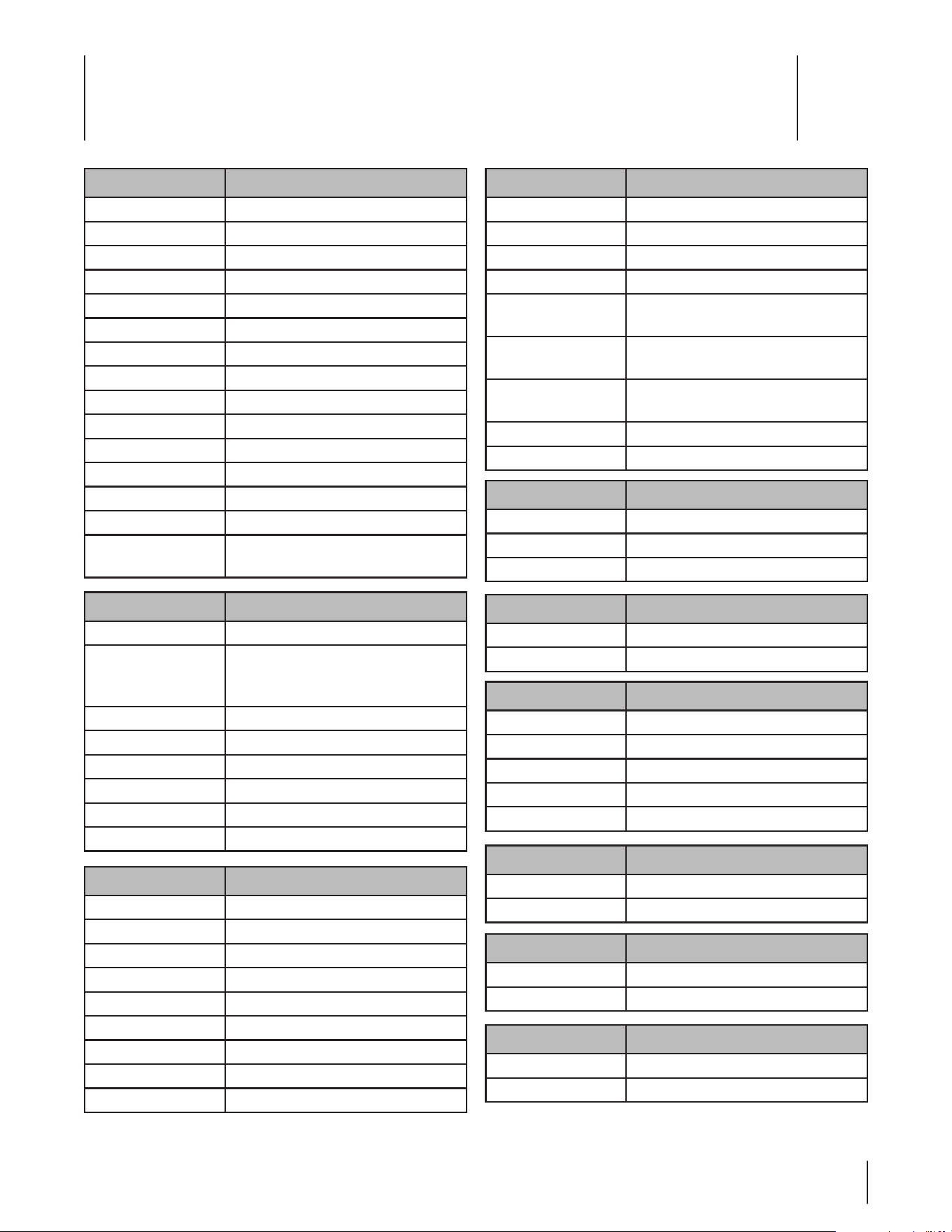
Description Description
Horn Gadget/Grab Bar
Acrylic Windshield AM/FM CD Radio
14” Aluminum Rims & Off-Road Tires (Set of 4) 12” Aluminum Rims (Set of 4)
Electric Bed Lift Raised Bed Gates
Signals & Brake Lights Spreader
Heavy Duty Bed Liner Super Trapp Sport Exhaust
Soft Roof w/Rear Window Bench Seat
Reverse Back-up Alarm Poly Canopy
Soft Doors Gun Boot & Mount
Heavy Duty Alternator * (Kohler Engines) Dual Purpose Tires & Black Steel Rims (Set of 4)
Light Bar Turf Tires & Black Steel Rims (Set of 4)
Mile Marker 3500 Lb. Winch Digital Speedometer & Fuel Gauge
Hood Rack Warn 4000 Lb. Winch
Electrical Accessory Harness 22 Cubic Foot Dump Cart
Front Receiver Warn Winch Kit (HD Winch)
72” Super Duty Blade (Manual Angle) Buss Bar**
Fog Light Kit Electric Angle (Requires 72” Super Duty Blade)
Rear View Mirror Integrated Light Bar
Rear Panel & Head Rests Tip-Out Glass Windshield & Mirror (Deluxe Cab Component)
Bed Mat Hard Roof & Rear Windshield (Deluxe Cab Component)
Floor Mats (Set of 2) Hard Doors (Deluxe Cab Component)
Electric Wiper & Lights (Deluxe Cab Component)
NOTE: For parts or accessories, contact your local Cub Cadet dealer. To locate the dealer nearest you call (877) 282-8684 or log onto
www.cubcadet.com.
* Recommended for installing electrical attachments on 18HP & 20HP units
** Recommended for installing multiple electrical attachments
Specifications
9
25
NOTE: Specifications subject to change without notice.
Engine/Electrical
Make 4x2 - 18HP* Kohler Command® V-Twin OHV
4x4 - 20HP* Kohler Command® V-Twin OHV
Type/ Cylinders 4 Cycle Gas/ 2 Cylinders
Displacement 38.0 cu. in. (624cc)
Maximum Torque 32.6 lb/ft @ 2600 RPM
Ignition Transistor Controlled
Lubrication Full Pressure w/ Filter
Speed (No Load) 1,300 RPM(idle)/ 3,850 RPM (fast)
Cooling System Air
Air Cleaner Replaceable, dual element
Battery 450 Cold Cranking Amps
Alternator 12 Volt-15 Amp Regulated
Headlights Two, 37.5 Watt Incandescent
Wiring Automotive - Style Fused Control System
Suspension Front & Rear - Fully Independent Dual A-
Arms with Coil Over Shocks
Transmission
Type Continuously Variable (CVT - w/ CVT Cover)
Differential Lock Rear - Standard
Hand Operated
Front - Flip Switch in Dash (4x4 Only)
Drive Chain N/A
Ground Speed 0-30 mph
Transaxle Fully Enclosed, Oil Bath
Gear Selection Forward Hi-Low (4x4 only), Neutral, Reverse
Overall Reduction Ratio Low 23.8:1 (4x4 Only)/ High 13.4:1
Rear Axle Housing Cast Iron
Features
Rear Hitch Standard 2” Rear Receiver
Dual Cup Holders Standard
Additional Storage Dash Box
Power Port 12V, Dash Mounted
Front Bumper Standard
Front Brush Guard Standard - (Front bumper required)
Electric Bed Lift Optional
Rubber Floor Mats Optional
Horn Optional
Dimensions
Length/ Width 119” x 63.5”
Tread Center F: 52”/ R: 50”
Height (Overall) 78”
Wheelbase 78”
Weight (Including Fuel
& Fluids)
1,650 lbs.
Ground Clearance
(Under Transaxle)
9”
Ground Clearance
(Under Footboard)
10.5”
Turn Clearance Circle 22.0 ft.
Bed 51 5/8”L x 42”W x 11 1/2” H
Operation
Brake Type Four Wheel 8” Hydraulic Disc
Parking Brake Hand Operated Mechanical Disc
Steering Rack & Pinion
Fuel System
Capacity 7 Gallons
Low Fuel Indicator Dash Mounted Indicator Light
Capacity
Volume - Cargo Box 14.4 cu. ft.
Cargo Box Capacity 1000 lbs.
Seating - Capacity/Type 2/ Professional High Back
Towing Capacity 1,400 lbs.
Payload Capacity** 1,400 lbs.
Ground Pressure (Max.)
w/200 lb. Operator Only N/A (Trail Tires)
Fully Loaded Vehicle N/A (Trail Tires)
Cargo Box
Material 16-Gauge Steel
Attachment Rubber Isolated
Tires
Trail Front 25” x 10” - 12” (All Four Tires on 4x2)
Trail Rear 25” x 11” - 12”
* As rated by engine manufacturer.
** Includes 200 lb. operator, 200 lb. passenger, and maximum bed capacity.
Kohler Command® V-Twin OHV Models

A Section 10 — SpecificationS
NOTE: Specifications subject to change without notice.
Engine/Electrical
Make 31HP* Kohler® Aegis EFI
Type/ Cylinders 4 Cycle Gas/ 2 Cylinders
Displacement 748cc
Maximum Torque 47.7ft. Lb. at 2400rpm
Ignition Mechanically Controlled
Lubrication Full Pressure w/ Filter
Speed (No Load) 1,000 RPM(idle)/ 4,200 RPM (fast)
Cooling System Liquid
Air Cleaner Heavy-duty replaceable, remote dual
element
Battery 450 Cold Cranking Amps
Alternator 12 Volt-60 Regulated, 65 Amp
Headlights Two, 37.5 Watt Incandescent
Wiring Automotive - Style Fused Control System
Suspension Front & Rear - Fully Independent Dual A-
Arms with Coil Over Shocks
Transmission
Type Continuously Variable (CVT)
Differential Lock Rear - Standard
Hand Operated
Front - Flip Switch in Dash
Drive Chain N/A
Ground Speed 0-35 mph
Transaxle Fully Enclosed, Oil Bath
Gear Selection Forward Hi-Low, Neutral, Reverse
Overall Reduction Ratio Low 29.2:1/ High 16.4:1
Rear Axle Housing Cast Iron
Features
Rear Hitch Standard 2” Rear Receiver
Dual Cup Holders Standard
Additional Storage Dash Box
Power Port 12V, Dash Mounted
Front Bumper Standard
Front Brush Guard Standard - (Front bumper required)
Electric Bed Lift Optional
Rubber Floor Mats Optional
Horn Optional
Dimensions
Length/ Width 119” x 63.5”
Tread Center F: 52”/ R: 50”
Height (Overall) 78”
Wheelbase 78”
Weight (Including Fuel
& Fluids)
1,650 lbs.
Ground Clearance
(Under Transaxle)
9”
Ground Clearance
(Under Footboard)
11”
Turn Clearance Circle 22.0 ft.
Bed 51 5/8”L x 42”W x 11 1/2” H
Operation
Brake Type Four Wheel 8” Hydraulic Disc
Parking Brake Hand Operated Mechanical Disc
Steering Rack & Pinion
Fuel System
Capacity 7 Gallons
Low Fuel Indicator Dash Mounted Indicator Light
Capacity
Volume - Cargo Box 14.4 cu. ft.
Cargo Box Capacity 1,000 lbs.
Seating - Capacity/Type 2/ Sport
Towing Capacity 1,400 lbs.
Payload Capacity** 1,400 lbs.
Ground Pressure (Max.)
w/200 lb. Operator Only N/A (Trail Tires)
Fully Loaded Vehicle N/A (Trail Tires)
Cargo Box
Material 16-Gauge Steel
Attachment Rubber Isolated
Tires
Trail Front 26” x 10” - 12”
Trail Rear 26” x 11” - 12”
* As rated by engine manufacturer.
** Includes 200 lb. operator, 200 lb. passenger, and maximum bed capacity.
Kohler® Aegis EFI Models

ASection 10 — SpecificationS
NOTE: Specifications subject to change without notice.
Engine/Electrical
Make 21.9HP* Yanmar®
Type/ Cylinders 4 Cycle Diesel/ 3 Cylinders
Displacement 854cc
Maximum Torque 36.9 ft. lb. @ 2400 RPM
Ignition Mechanically Controlled
Lubrication Full Pressure w/ Filter
Speed (No Load) 1,000 RPM(idle)/ 3,800 RPM (fast)
Cooling System Liquid
Air Cleaner Heavy-duty replaceable, remote dual
element
Battery 450 Cold Cranking Amps
Alternator 12 Volt-60 Regulated, 65 Amp
Headlights Two, 37.5 Watt Incandescent
Wiring Automotive - Style Fused Control System
Suspension Front & Rear - Fully Independent Dual A-
Arms with Coil Over Shocks
Transmission
Type Continuously Variable (CVT)
Differential Lock Rear - Standard
Hand Operated
Front - Flip Switch in Dash
Drive Chain N/A
Ground Speed 0-30 mph
Transaxle Fully Enclosed, Oil Bath
Gear Selection Forward Hi-Low, Neutral, Reverse
Overall Reduction Ratio Low 29.2:1/ High 16.4:1
Rear Axle Housing Cast Iron
Features
Rear Hitch Standard 2” Rear Receiver
Dual Cup Holders Standard
Additional Storage Dash Box
Power Port 12V, Dash Mounted
Front Bumper Standard
Front Brush Guard Standard - (Front bumper required)
Electric Bed Lift Optional
Rubber Floor Mats Optional
Horn Optional
Dimensions
Length/ Width 119” x 63.5”
Tread Center F: 52”/ R: 50”
Height (Overall) 73”
Wheelbase 78”
Weight (Including Fuel
& Fluids)
1,650 lbs.
Ground Clearance
(Under Transaxle)
9”
Ground Clearance
(Under Footboard)
11”
Turn Clearance Circle 22.0 ft.
Bed 51 5/8”L x 42”W x 11 1/2” H
Operation
Brake Type Four Wheel 8” Hydraulic Disc
Parking Brake Hand Operated Mechanical Disc
Steering Rack & Pinion
Fuel System
Capacity 7 Gallons
Low Fuel Indicator Dash Mounted Indicator Light
Capacity
Volume - Cargo Box 14.4 cu. ft.
Cargo Box Capacity 1,000 lbs.
Seating - Capacity/Type 2/ Sport
Towing Capacity 1,400 lbs.
Payload Capacity** 1,400 lbs.
Ground Pressure (Max.)
w/200 lb. Operator Only N/A (Trail Tires)
Fully Loaded Vehicle N/A (Trail Tires)
Cargo Box
Material 16-Gauge Steel
Attachment Rubber Isolated
Tires
Trail Front 25” x 10” - 12”
Trail Rear 25” x 11” - 12”
* As rated by engine manufacturer.
** Includes 200 lb. operator, 200 lb. passenger, and maximum bed capacity.
Yanmar Diesel Models

Tro ubleshooting
10
28
Problem Cause(s)
Engine will not start 1. Battery has low voltage.
2. Loose or corroded battery connections.
3. Fuse is blown.
4. Spark plug wire is loose or disconnected (Gas Powered Units Only!)
5. Faulty spark plug or coil (Gas Powered Units Only!)
6. Air or water is in the fuel system. Pump the manual prime on the fuel pump.
+(Diesel Units Only!)
7. In Winter, oil viscosity increases, and engine revolution is slow.
(Diesel Units Only!)
8. No Fuel or improper fuel.
9. Plugged fuel filter.
10. Defective starter solenoid.
11. Open-circuit in wiring.
Engine is difficult to start 1. Engine is cold.
2. Plugged fuel filter.
3. Carburetor not adjusted properly or dirty. (Air-Cooled, Gas Powered Units Only!)
4. Engine oil viscosity too heavy.
5. Spark plug is fouled. (Gas Powered Units Only!)
6. Faulty spark plug or wire. (Gas Powered Units Only!)
7. Loose or corroded electrical connections.
8. Stale or improper fuel.
9. Choke (if equipped) not being used or adjusted properly. (Air-Cooled Units Only!)
Engine misses under load 1. Faulty spark plug. (Gas Powered Units Only!)
2. Stale or dirty fuel.
3. Plugged fuel filter.
4. Faulty coil or wire. (Gas Powered Units Only!)
Engine vapor locks 1. Poor quality fuel.
2. Very hot weather conditions.
3. Fuel tank vent plugged.
4. Dirt in fuel filter.
Continued on next page

29Section 10 — troubleShooting
Problem Cause(s)
Engine runs unevenly 1. Loose electrical connections.
2. Choke (if equipped) or throttle cable sticking.
3. Fuel line or fuel filter plugged.
4. Stale or dirty fuel.
5. Improper fuel.
6. Air cleaner element plugged.
7. Carburetor not adjusted correctly. (Air-Cooled Units Only!)
8. Spark plug is fouled. (Gas Powered Units Only!)
Engine overheats 1. Air cleaner element missing or plugged.
2. Carburetor air intake tube plugged. (Air-Cooled Units Only!)
3. Engine oil low.
4. Engine operated too long at slow engine speed. (Gas Powered Units Only!)
Engine knocks 1. Low engine speed. (Gas Powered Units Only!)
2. Stale or low octane fuel. (Gas Powered Units Only!)
3. Engine overloaded. (Gas Powered Units Only!)
Engine fumes are colored (Black)
(Diesel Units Only!)
1. Fuel quality is poor.
2. Too much oil.
3. The air cleaner is clogged.
Engine fumes are colored (Blue white)
(Diesel Units Only!)
1. The inside of exhaust muffler is dumped with fuel.
2. Injection nozzle trouble.
3. Poor quality fuel.
Engine overheats
(Diesel Units Only!)
1. Engine overloaded.
2. Low coolant level.
3. Dirty radiator core or grille screen.
4. Coolant flow route corroded.
5. Air cleaner element missing or plugged.
6. Engine oil low.
7. Engine operated too long at slow engine speed.
Engine loses power 1. Engine overheating.
2. Too much oil in engine.
3. Faulty spark plug. (Gas Powered Units Only!)
4. Fuel supply being restricted.
5. Fuel filter plugged.
6. Fuel line pinched or kinked.
7. Fuel pump output not adjusted to specification. (Gas Powered Units Only!)
8. Improper fuel. (Gas Powered Units Only!)
9. Insufficient or dirty fuel. (Diesel Units Only!)
10. Air cleaner element plugged.
Continued on next page

30 Section 10 — troubleShooting
Problem Cause(s)
Starter does not work 1. Loose or corroded connections.
2. Low battery output
3. Sulfate or worn-out battery.
4. Faulty starter.
Starter cranks slowly 1. Low battery output.
2. Sulfated or worn-out battery.
3. Engine oil too heavy.
4. Loose or corroded connections.
Entire electrical system does not work 1. Blown fuse.
2. Loose or corroded connections.
3. Sulfated or worn-out battery.
Dead battery 1. Shorted starter solenoid.
2. Key switch not turned to STOP position.
3. Sulfated or worn-out battery.
Battery light comes on when engine is
running
1. Low engine speed.
2. Faulty voltage regulator.
3. Faulty battery.
4. Faulty alternator or loose alternator belt.
5. Grounded wire in circuit.
Indicator lights do not come on when key
switch is in START position
1. Faulty bulb.
2. Faulty wiring.
3. Faulty sensor.
Battery will not take a charge 1. Dead battery.
2. Loose or corroded connections.
3. Sulfated or worn-out battery.
4. Fluid level low.
Difficult to shift 1. Gears not lined up. Blip throttle and let it return to idle. If still hard to shift, contact
your nearest Cub Cadet dealer.

Notes
11
31

32 Notes

33Notes

FEDERAL EMISSION CONTROL WARRANTY STATEMENT
YOUR WARRANTY RIGHTS AND OBLIGATIONS
MTD Consumer Group Inc and the United States Environmental Protection Agency (EPA) are pleased to explain the emission (evaporative and/or exhaust) control
system (ECS) warranty on your outdoor 2008 and later small off-road spark-ignited engine and equipment (outdoor equipment engine). New outdoor equipment
engines must be designed, built and equipped to meet the U.S. EPA’s regulations for off-road utility vehicles with spark ignited engines. MTD Consumer Group Inc
must warrant the ECS on your outdoor equipment engine for the period of time listed below provided there has been no abuse, neglect or improper maintenance of
outdoor equipment engine.
Your ECS may include parts such as the carburetor, fuel-injection system, the ignition system, catalytic converter, fuel tanks, fuel lines, fuel caps, valves, canisters,
filters, vapor hoses, clamps, connectors, and other associated emission-related components.
Where a warrantable condition exists, MTD Consumer Group Inc will repair your outdoor equipment engine at no cost to you including diagnosis, parts
and labor.
MANUFACTURER’S WARRANTY COVERAGE:
This emission control system is warranted for 500 hours or at least for 30 months, whichever comes first. If any emission-related part on your outdoor equipment
engine is defective, the part will be repaired or replaced by MTD CONSUMER GROUP INC.
OWNER’S WARRANTY RESPONSIBILITIES:
As the outdoor equipment engine owner, you are responsible for performance of the required maintenance listed in your owner’s manual. MTD Consumer Group
Inc recommends that you retain all receipts covering maintenance on your outdoor equipment engine, but MTD Consumer Group Inc cannot deny warranty solely
for the lack of receipts.
As the outdoor equipment engine owner, you should however be aware that MTD Consumer Group Inc may deny you warranty coverage if your outdoor equipment
engine or a part has failed due to abuse, neglect, or improper maintenance or unapproved modifications.
You are responsible for presenting your outdoor equipment engine to MTD Consumer Group Inc’s distribution center or service center as soon as the problem
exists. The warranty repairs should be completed in a reasonable amount of time, not to exceed 30 days. If you have a question regarding your warranty coverage,
you should contact the MTD Consumer Group Inc Service Department at 1-800-800-7310 or via email at http://support.mtdproducts.com.
GENERAL EMISSIONS WARRANTY COVERAGE:
MTD Consumer Group Inc warrants to the ultimate purchaser and each subsequent purchaser that the outdoor equipment engine is: Designed, built and equipped
so as to conform with all applicable regulations; and free from defects in materials and workmanship that cause the failure of a warranted part to be identical in all
material respects to that part as described in MTD Consumer Group Inc’s application for certification.
The warranty period begins on the date the outdoor equipment engine is delivered to an ultimate purchaser or first placed into service. The warranty period is 500
hours or at least for 30 months, whichever comes first.
Subject to certain conditions and exclusions as stated below, the warranty on emission-related parts is as follows:
1. Any warranted part that is not scheduled for replacement as required maintenance in the written instructions supplied, is warranted for the warranty period
stated above. If the part fails during the period of warranty coverage, the part will be repaired or replaced by MTD Consumer Group Inc according to subsection
(4) below. Any such part repaired or replaced under warranty will be warranted for the remainder of the period.
2. Any warranted part that is scheduled only for regular inspection in the written instructions supplied is warranted for the warranty period stated above. Any such
part repaired or replaced under warranty will be warranted for the remaining warranty period.
3. Any warranted part that is scheduled for replacement as required maintenance in the written instructions supplied is warranted for the period of time before the
first scheduled replacement date for that part. If the part fails before the first scheduled replacement, the part will be repaired or replaced by MTD Consumer
Group Inc according to subsection (4) below. Any such part repaired or replaced under warranty will be warranted for the remainder of the period prior to the
first scheduled replacement point for the part.
4. Repair or replacement of any warranted part under the warranty provisions herein must be performed at a warranty station at no charge to the owner.
5. Notwithstanding the provisions herein, warranty services or repairs will be provided at all of our distribution centers that are franchised to service the subject
engines or equipment.
6. The outdoor equipment engine owner will not be charged for diagnostic labor that is directly associated with diagnosis of a defective, emission-related war-
ranted part, provided that such diagnostic work is performed at a warranty station.
7. MTD Consumer Group Inc is liable for damages to other engine or equipment components proximately caused by a failure under warranty of any warranted
part.
8. Throughout the off-road engine and equipment warranty period stated above, MTD Consumer Group Inc will maintain a supply of warranted parts sufficient to
meet the expected demand for such parts.
9. Any replacement part may be used in the performance of any warranty maintenance or repairs and must be provided without charge to the owner. Such use will
not reduce the warranty obligations of MTD Consumer Group Inc.
10. The use of any non-exempted add-on or modified parts by the ultimate purchaser will be grounds for disallowing a warranty claim. MTD Consumer Group Inc
will not be liable to warrant failures of warranted parts caused by the use of a non-exempted add-on or modified part.

GDOC-100233 Rev. C
WARRANTED PARTS:
The repair or replacement of any warranted part otherwise eligible for warranty coverage may be excluded from such warranty coverage if MTD Consumer Group
Inc demonstrates that the outdoor equipment engine has been abused, neglected, or improperly maintained, and that such abuse, neglect, or improper mainte-
nance was the direct cause of the need for repair or replacement of the part. That notwithstanding, any adjustment of a component that has a factory installed,
and properly operating, adjustment limiting device is still eligible for warranty coverage. Further, the coverage under this warranty extends only to parts that were
present on the off-road engine and equipment purchased.
The following emission warranty parts are covered (if applicable):
(1) Fuel Metering System
• Cold start enrichment system (soft choke)
• Carburetor and internal parts (or fuel injection system)
• Fuel pump
• Fuel tank
(2) Air Induction System
• Air cleaner
• Intake manifold
(3) Ignition System
• Spark plug(s)
• Magneto ignition system
(4) Exhaust System
• Catalytic converter
• SAI (Reed valve)
(5) Miscellaneous Items Used in Above System
• Vacuum, temperature, position, time sensitive valves and switches
• Connectors and assemblies
(6) Evaporative Control
• Fuel hose
• Fuel hose clamps
• Tethered fuel cap
• Carbon canister
• Vapor lines

The limited warranty set forth below is given by Cub Cadet LLC with
respect to new merchandise purchased and used in the United States,
its possessions and territories, and by MTD Products Limited with
respect to new merchandise purchased and used in Canada and/or its
territories and possessions.
This warranty is in addition to any applicable emissions warranty
provided with your product.
For non-commercial use: Cub Cadet warrants this product (excluding
Batte ries, as described below) against defects in material and
workmanship for a period of one (1) year from the date of original
retail purchase or lease.
For commercial uses and applications: Cub Cadet warrants this
product (excluding Batteries, as described below) against defects in
material and workmanship for a period of six (6) months from the
date of original retail purchase or lease.
“Cub Cadet” will, at its option, repair or replace, free of charge, any
part found to be defective in materials or workmanship. This limited
warranty shall only apply if this product has been operated and
maintained in accordance with the Operator’s Manual furnished with
the product, and has not been subject to misuse, abuse, neglect,
accident, improper maintenance, alteration, vandalism, theft, fire,
water, or damage because of other peril or natural disaster. Damage
resulting from the installation or use of any part, accessory or
attachment not approved by Cub Cadet for use with the product(s)
covered by this manual will void your warranty as to any resulting
damage.
Batteries have a one-year prorated limited warranty against defects
in material and workmanship, with 100% replacement during the
first three months. After three months, the battery replacement
credit is based on the months remaining in the twelve (12) month
period dating back to the original date of original sale or lease. Any
replacement battery will be warranted only for the remainder of the
original warranty period.
HOW TO OBTAIN SERVICE: Warranty service is available, WITH
PROOF OF PURCHASE, through your local authorized service
dealer. To locate the dealer in your area:
In the U.S.A.
To locate the dealer in your area, check your Yellow Pages, or contact
Cub Cadet LLC at P.O. Box 361131, Cleveland, Ohio 44136-0019, or
call 1-877-282-8684, or log on to our Web site at www.cubcadet.
com.
In Canada
Contact MTD Products Limited, Kitchener, ON N2G 4J1, or call
1-800-668-1238 or log on to our Web site at www.mtdcanada.
com.
This limited warranty does not provide coverage in the following
cases:
a. The engine or component parts thereof. These items may
carry a separate manufacturer’s warranty. Refer to applicable
manufacturer’s warranty for terms and conditions.
b. Routine maintenance items such as lubricants, filters, tune-ups,
brake adjustments, clutch adjustments and normal deterioration of
the exterior finish due to use or exposure.
c. Cub Cadet does not extend any warranty for products sold or
exported outside of the United States and/or Canada, and their
respective possessions and territories, except those sold through
Cub Cadet’s authorized channels of export distribution.
d. Replacement parts that are not genuine Cub Cadet parts.
e. Service completed by someone other than an authorized service
dealer.
f. Transportation charges and service calls.
No implied warranty, including any implied warranty of mer-
chantability of fitness for a particular purpose, applies after the
applicable period of express written warranty above as to the
parts as identified. No other express warranty, whether written
or oral, except as mentioned above, given by any person or
entity, including a dealer or retailer, with respect to any product,
shall bind Cub Cadet. During the period of the warranty, the
exclusive remedy is repair or replacement of the product as set
forth above.
The provisions as set forth in this warranty provide the sole and
exclusive remedy arising from the sale. Cub Cadet shall not be
liable for incidental or consequential loss or damage including,
without limitation, expenses incurred for substitute or replace-
ment lawn care services or for rental expenses to temporarily
replace a warranted product.
Some states do not allow the exclusion or limitation of incidental
or consequential damages, or limitations on how long an implied
warranty lasts, so the above exclusions or limitations may not apply
to you.
In no event shall recovery of any kind be greater than the amount
of the purchase price of the product sold. Alteration of safety
features of the product shall void this warranty. You assume the
risk and liability for loss, damage, or injury to you and your property
and/or to others and their property arising out of the misuse or
inability to use the product.
This limited warranty shall not extend to anyone other than the
original purchaser or to the person for whom it was purchased as a
gift.
HOW STATE LAW RELATES TO THIS WARRANTY: This limited
warranty gives you specific legal rights, and you may also have other
rights that vary in different jurisdictions.
IMPORTANT: Owner must present Original Proof of Purchase to
obtain warranty coverage.
Cub Cadet LLC, P.O. BOX 361131 CLEVELAND, OHIO 44136-0019; Phone: 1-877-282-8684
MTD Canada Limited - KITCHENER, ON N2G 4J1; Phone 1-800-668-1238
GDOC-100094 REV. B
CUB CADET LLC
MANUFACTURER’S LIMITED WARRANTY FOR
UTILITY VEHICLES

