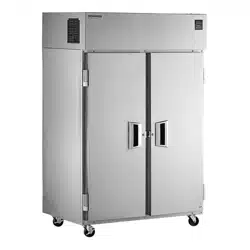
6000XL & 6100XL Series
Reach Ins
Original Instructions
Installation, Operation and Maintenance Manual
This manual is updated as new information and models are released. Visit our website for the latest manual.
Fresh Soluons, Fit For You
Part Number: 9294254 01/23
Safety Notices
n
Warning
Read this manual thoroughly before operating, installing
or performing maintenance on the equipment. Failure
to follow instructions in this manual can cause property
damage, injury or death.
DANGER
Do not install or operate equipment that has been
misused, abused, neglected, damaged, or altered/
modified from that of original manufactured
specifications.
DANGER
Keep power cord AWAY from HEATED surfaces. DO NOT
immerse power cord or plug in water. DO NOT let power
cord hang over edge of table or counter.
DANGER
All utility connections and fixtures must be maintained
in accordance with Local and national codes.
n
Warning
Authorized Service Representatives are obligated to
follow industry standard safety procedures, including,
but not limited to, local/national regulations for
disconnection / lock out / tag out procedures for all
utilities including electric, gas, water and steam.
n
Warning
Do not store or use gasoline or other flammable vapors
or liquids in the vicinity of this or any other appliance.
Never use flammable oil soaked cloths or combustible
cleaning solutions, for cleaning.
n
Warning
This product contains chemicals known to the State
of California to cause cancer and/or birth defects or
other reproductive harm. Operation, installation, and
servicing of this product could expose you to airborne
particles of glasswool or ceramic fibers, crystalline
silica, and/or carbon monoxide. Inhalation of airborne
particles of glasswool or ceramic fibers is known to the
State of California to cause cancer. Inhalation of carbon
monoxide is known to the State of California to cause
birth defects or other reproductive harm.
n
Warning
Do not use electrical appliances or accessories other
than those supplied by the manufacturer.
n
Warning
Use caution when handling metal surface edges of all
equipment.
n
Warning
This appliance is not intended for use by persons
(including children) with reduced physical, sensory
or mental capabilities, or lack of experience and
knowledge, unless they have been given supervision
concerning use of the appliance by a person responsible
for their safety. Do not allow children to play with this
appliance.
,
Caution
Use caution handling, moving and use of the R290
refrigerators to avoid either damaging the refrigerant
tubing or increasing the risk of a leak. Components
shall be replaced with like components. Servicing shall
be done by a factory authorized service personnel to
minimize the risk of possible ignition due to incorrect
parts or improper service.
Notice
Proper installation, care and maintenance are
essential for maximum performance and trouble-free
operation of your equipment. Visit our website www.
mtwkitchencare.com for manual updates, translations,
or contact information for service agents in your area.
Notice
This product utilizes Ecomate blowing agent methyl
formate

Part Number: 9294254 01/23 3
Section 1
General Information
Model Numbers .................................................................................................................. 5
Serial Number Information ...............................................................................................5
Warranty Information ........................................................................................................ 5
Regulatory Certifications ..................................................................................................5
Section 2
Installation
Location ..............................................................................................................................7
Weight of Equipment .........................................................................................................8
Clearance Requirements ....................................................................................................8
Drain Connections ..............................................................................................................8
Dimensions ......................................................................................................................... 9
Electrical Service ..............................................................................................................10
Energy Star .......................................................................................................................11
Refrigeration ....................................................................................................................11
Leveling .............................................................................................................................11
Stabilizing .........................................................................................................................11
Leg & Caster Installation ..................................................................................................11
Section 3
Operation
R290 Controls/Programming/Settings ...........................................................................14
Refrigerator Settings .......................................................................................................................... 14
Refrigerator Defrost ............................................................................................................................14
Freezer Settings ................................................................................................................................... 15
Freezer Defrost ..................................................................................................................................... 15
R290 Temperature Control & Display ...........................................................................................16
R290 Evaporator Fan Operation ..................................................................................................... 16
R290 Changing Display from Fahrenheit to Celsius on ERC112 Control ......................... 17
Section 4
Maintenance
Cleaning and Sanitizing Procedures ...............................................................................19
General .................................................................................................................................................... 19
Interior Cleaning .................................................................................................................................. 20
Exterior Cleaning ................................................................................................................................. 20
Drain ......................................................................................................................................................... 21
Cleaning the Condenser Coil ..........................................................................................................21
Casters ..................................................................................................................................................... 21
Doors/Hinges ........................................................................................................................................ 21
Preventing Blower Coil Corrosion .................................................................................................21
Section 5
Troubleshooting
Problem -> Cause -> Correction Chart ............................................................................ 22
Table of Contents

4 Part Number: 9294254 01/23
Table of Contents (continued)
THIS PAGE INTENTIONALLY LEFT BLANK
Part Number: 929254 01/23 5
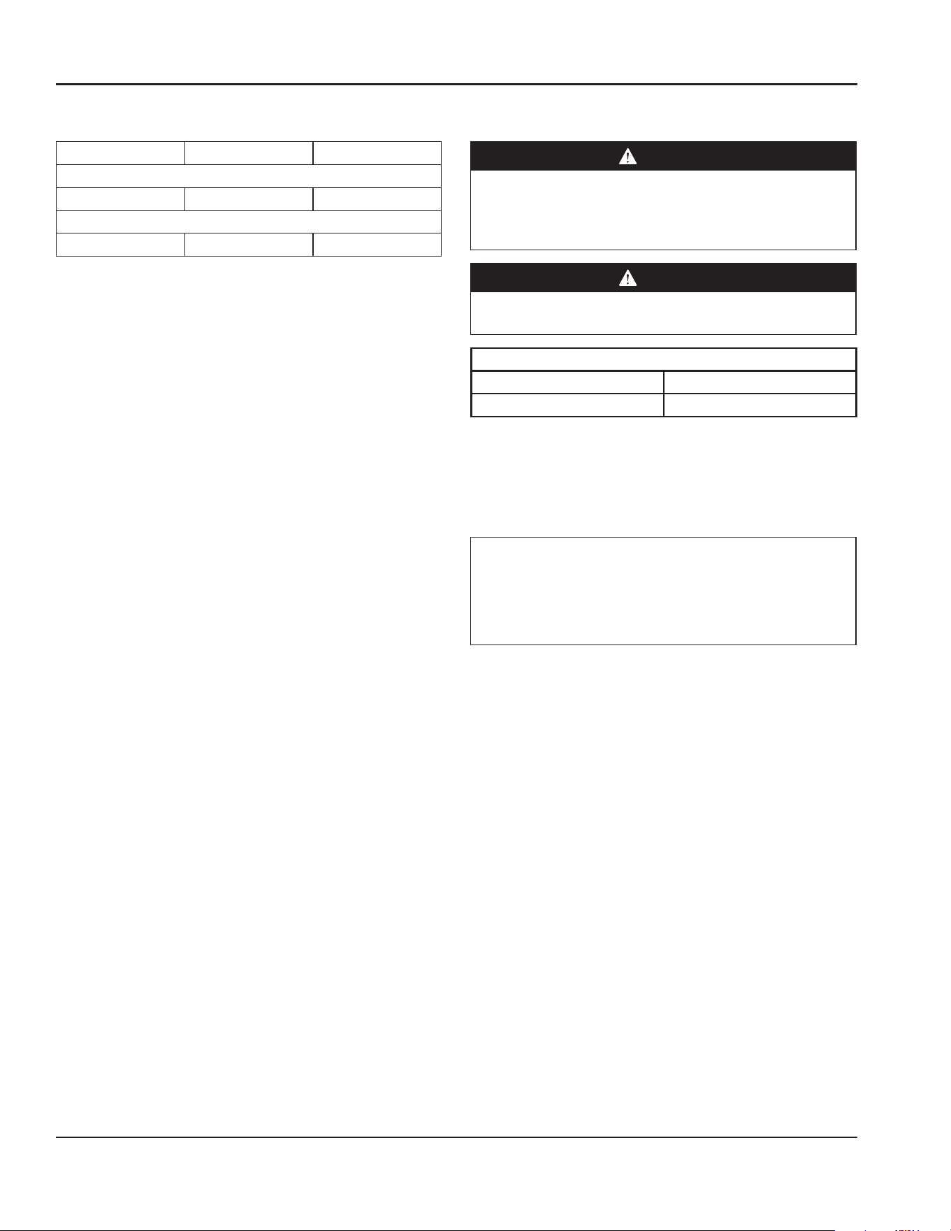
Model Numbers
This manual covers the following models:
1 Section Refrigerators
Solid Doors
6025XL-S
1 Section Freezer
Solid Doors
6125XL-S
Serial Number Information
The serial number is on the identification plate that also
includes the model number. The identification plate is
located inside the cabinet on the left interior wall.
Always have the serial number of your unit available
when calling for parts or service.
Warranty Information
Visit
http://www.delfield.com/warranty to:
• Register your product for warranty.
• Verify warranty information.
• View and download a copy of your warranty.
Regulatory Certifications
Models are certified by:
• National Sanitation Foundation (NSF)
• Underwriters Laboratories (UL)
• Underwriters Laboratories of Canada (cUL)
Section 1
General Information
1 Section Refrigerators
Glass Doors Solid Doors
6025XL-G(H) 6025XL-S(H)
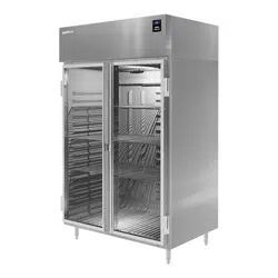
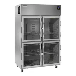
2 Section Refrigerators
Glass Doors Solid Doors
6051XL-G(H) 6051XL-S(H)
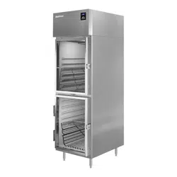
1 Section Freezer
Solid Doors
6125XL-S(H)
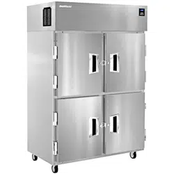
2 Section Freezer
Solid Doors
6151XL-S(H)

6 Part Number: 9294254 01/23
General Information Section 1
THIS PAGE INTENTIONALLY LEFT BLANK
Part Number: 9294254 01/23 7
DANGER
Installation must comply with all applicable fire and
health codes in your jurisdiction.
DANGER
Use appropriate safety equipment during installation
and servicing.
n
Warning
Do not damage the refrigeration circuit when installing,
maintaining or servicing the unit.
Location
n
Warning
This equipment must be positioned so that the plug is
accessible unless other means for disconnection from
the power supply (e.g., circuit breaker or disconnect
switch) is provided.
n
Warning
Adequate means must be provided to limit the
movement of this appliance without depending on or
transmitting stress to the electrical conduit or gas lines.
n
Warning
To avoid instability the installation area must be capable
of supporting the combined weight of the equipment
and product. Additionally the equipment must be level
side to side and front to back.
n
Warning
This equipment is intended for indoor use only. Do not
install or operate this equipment in outdoor areas.
The location selected for the equipment must meet the
following criteria. If any of these criteria are not met, select
another location.
• The location MUST be level, stable and capable of
supporting the weight of the equipment.
• The location MUST be free from and clear of
combustible materials.
• Equipment MUST be level both front to back and side to
side.
• Position the equipment so it will not tip or slide.
• Front casters MUST be locked once positioned.
• Recommended air temperature is 60° - 100°F
(16° - 38°C).
• Proper air supply for ventilation is REQUIRED AND
CRITICAL for safe and efficient operation. Refer to
Clearance Requirements chart on page 8.
• Do not obstruct the flow of ventilation air. Make sure the
air vents of the equipment are not blocked.
• Do not install the equipment directly over a drain.
Steam rising up out of the drain will adversely affect
operation, air circulation, and damage electrical /
electronic components.
Section 2
Installation
Installation Section 2
8 Part Number: 9294254 01/23
Weight of Equipment
Description Models Weight
1 Section Refrigerators
Solid Doors 6025XL-S 274 lbs (124 kg)
1 Section Freezers
Solid Doors 6125XL-S 274 lbs (124 kg)
Clearance Requirements
DANGER
Minimum clearance requirements are the same for
noncombustible locations as for combustible locations.
The flooring under the appliance must be made of a
noncombustible material.
DANGER
Risk of fire/shock. All minimum clearances must be
maintained. Do not obstruct vents or openings.
Top
6025XL-S 12.00” (30cm)
6125XL-S 20.00” (50cm)
• Keep the vents clean and free of obstruction.
• Casters or optional legs must be used and not removed.
Drain Connections
n
Warning
Moisture collecting from improper drainage can create a
slippery surface on the floor and a hazard to employees.
It is the owner’s responsibility to provide a container or
outlet for drainage.
Description Models Weight
1 Section Refrigerators
Glass Doors 6025XL-G(H) 338 lbs (153 kg)
Solid Doors 6025XL-S(H) 274 lbs (124 kg)
2 Section Refrigerators
Glass Doors 6051XL-G(H) 548 lbs (249 kg)
Solid Doors 6051XL-S(H) 454 lbs (206 kg)
1 Section Freezers
Solid Doors 6125XL-S(H) 274 lbs (124 kg)
2 Section Freezers
Solid Doors 6151XL-S(H) 454 lbs (206 kg)
Section 2 Installation
Part Number: 9294254 01/23 9
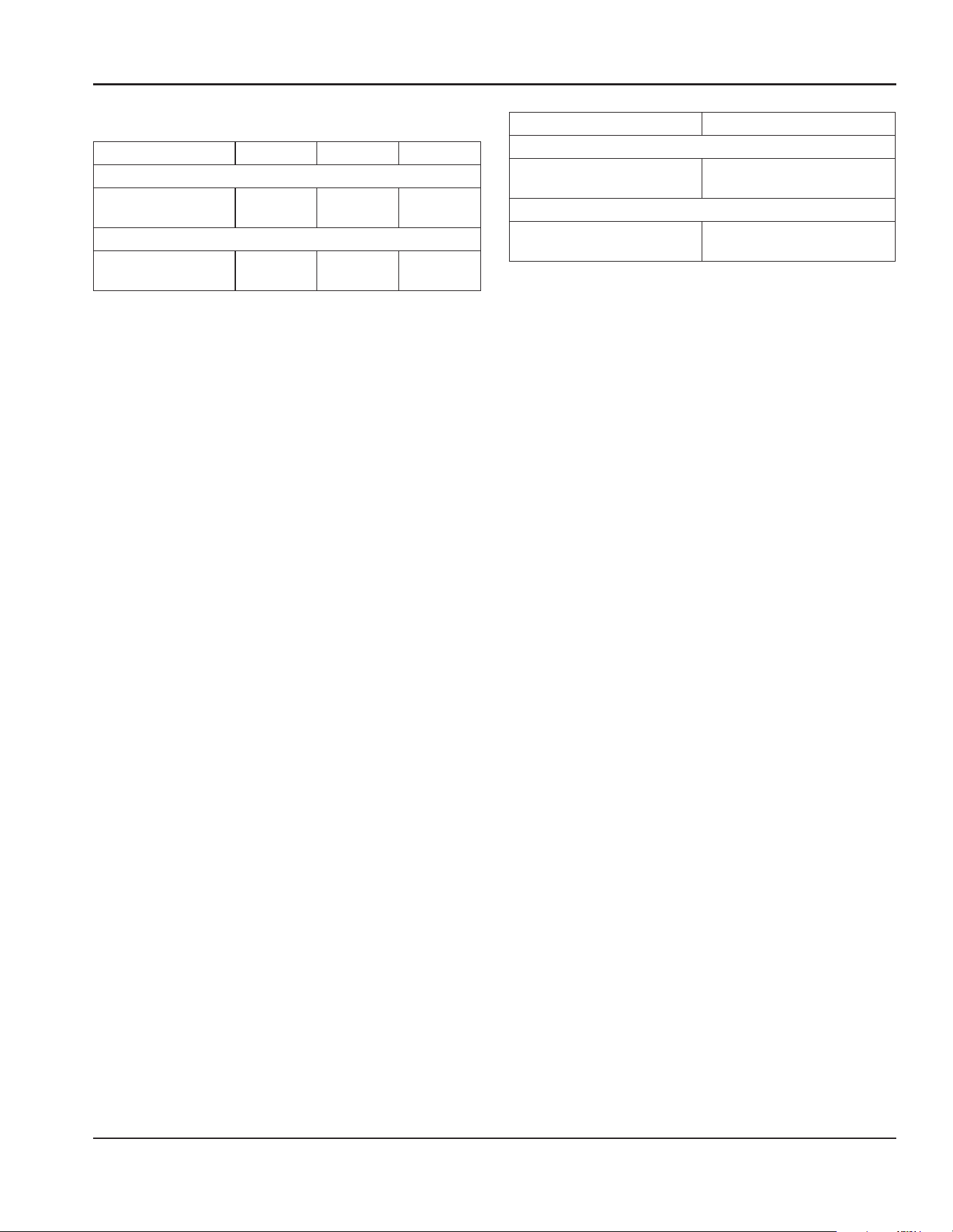
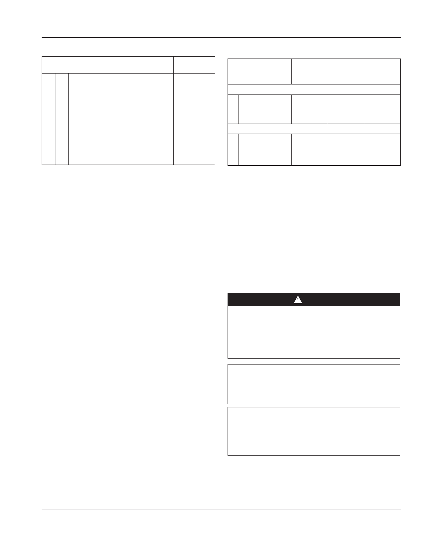
Dimensions
Model Length Depth Height
1 Section Refrigerators
6025XL-S 25.5”
(65cm)
32.38”
(82cm)
79.5”
(202cm)
1 Section Freezers
6125XL-S
25.5”
(65cm)
32.38”
(82cm)
79.5”
(202cm)
Model Volume
1 Section Refrigerators
6025XL-S
20ft
3
(595L)
1 Section Freezers
6125XL-S
20ft
3
(595L)
Model Length Depth Height
1 Section Refrigerators
6025XL-G(H) 25.5”
(65cm)
32.38”
(82cm)
79.5”
(202cm)
6025XL-S(H) 25.5”
(65cm)
32.38”
(82cm)
79.5”
(202cm)
2 Section Refrigerators
6051XL-G(H) 51”
(139cm)
32.38”
(82cm)
79.5”
(202cm)
6051XL-S(H)
51”
(139cm)
32.38”
(82cm)
79.5”
(202cm)
1 Section Freezers
6125XL-S(H)
25.5”
(65cm)
32.38”
(82cm)
79.5”
(202cm)
2 Section Freezers
6151XL-S(H) 51”
(139cm)
32.38”
(82cm)
79.5”
(202cm)
Model Volume
1 Section Refrigerators
6025XL-G(H)
6025XL-S(H)
20ft
3
(595L)
2 Section Refrigerators
6051XL-G(H)
6051XL-S(H)
43ft
3
(1303L)
1 Section Freezers
6125XL-S(H)
20ft
3
(595L)
2 Section Freezers
6151XL-S(H)
43ft
3
(1303L)
Installation Section 2
10 Part Number: 9294254 01/23
Electrical Service
DANGER
Check all wiring connections, including factory
terminals, before operation. Connections can become
loose during shipment and installation.
n
Warning
This appliance must be grounded and all field wiring
must conform to all applicable local and national
codes. Refer to rating plate for proper voltage. It is the
responsibility of the end user to provide the disconnect
means to satisfy the authority having jurisdiction.
• Plug units with R290 refrigerant into a receptacle that is
a minimum of 14” (36cm) above the floor.
• All electrical work, including wire routing and
grounding, must conform to local, state and national
electrical codes.
• The equipment must be grounded.
• A separate fuse/circuit breaker must be provided for
each unit.
• Check all green ground screws, cables and wire
connections to verify they are tight before start-up.
• The maximum allowable voltage variation is ±10% of
the rated voltage at equipment start-up (when the
electrical load is highest).
Ground Fault Circuit Interrupter
Ground Fault Circuit Interrupter (GFCI/GFI) protection is
a system that shuts down the electric circuit (opens it)
when it senses an unexpected loss of power, presumably
to ground. Manitowoc does not recommend the use of
GFCI/GFI circuit protection to energize our equipment.
If code requires the use of a GFCI/GFI then you must
follow the local code. The circuit must be dedicated, sized
properly and there must be a panel GFCI/GFI breaker. We
do not recommend the use of GFCI/GFI outlets to energize
our equipment as they are known for more intermittent
nuisance trips than panel breakers.
Rated Amperages, Horsepower, Voltage & Power Cord
Chart
Maximum 10ft (3m) cord with plug.
Models Amps HP V, Hz, Ph NEMA
Plug
Refrigerators
1 Section
6025XL-S(H)
4.2 0.22 120, 60, 1 5-15p
Freezers
1 Section
6125XL-S(H) 5.5 0.55 120, 60, 1 5-15p
Models Amps HP V, Hz, Ph NEMA
Plug
Refrigerators
1 Section
6025XL-G(H)
6025XL-S(H)
4.2 0.22 120, 60, 1 5-15p
2 Section
6051XL-G(H)
6051XL-S(H)
6.0 0.35 120, 60, 1 5-15p
Freezers
1 Section
6125XL-S(H) 5.5 0.55 120, 60, 1 5-15p
2 Section
6151XL-S(H) 10.0 0.68 120, 60, 1 5-15p
Section 2 Installation
Part Number: 9294254 01/23 11
Modelos
Tensión
(V~)
Corriente
(A)
Frecuencia
(Hz)
Capacidad
(L)
Consumo
límite
(Wh/L)
Consumo
de aparato
(Wh/L)
Ahorro
(%)
Cantidad
de
Enfriador
Comercial
6025XL-G(H)
115
4.2
60
594.6 12.2 4.7 61.4
113
6025XL-S(H)
4.2 594.6 12.2 4.9 59.8
6051XL-G(H) 6.0 1299.8 8.9 2.5 71.9
6051XL-S(H) 6.0 1299.8 8.9 3.2 64.0
6125XL-S(H) 5.5 594.6 12.2 4.7 61.4
6151XL-S(H) 10 1299.8 8.9 4.9 59.8
Energy Use For Energy Star® Certified Units
Models Energy Use
in kWh
Refrigerators
1 Section
6025XL-S 1.66
Freezers
1 Section
6125XL-S 5.78
Refrigeration
Model
BTU/Hour
Capacity
Heat of
Rejection
(BTU)
R290
Charge
1 Section Refrigerators
Solid
Full Height Doors
6025XL-S
1754 390 113g
1 Section Freezers
Solid
Full Height Doors
6125XL-S
1759 755 100g
Leveling
After the cabinet has been placed in the desired location,
cabinets with legs must be leveled. Level units from front to
back and from side to side. Leveling will insure proper door
operation and removal of condensate. Cabinets with casters
must have the caster brake set so the cabinet cannot move.
Stabilizing
It is very important that all legs are properly adjusted to
keep the cabinet level, evenly distribute the weight and to
make sure the unit will not rock, lean or be unstable.
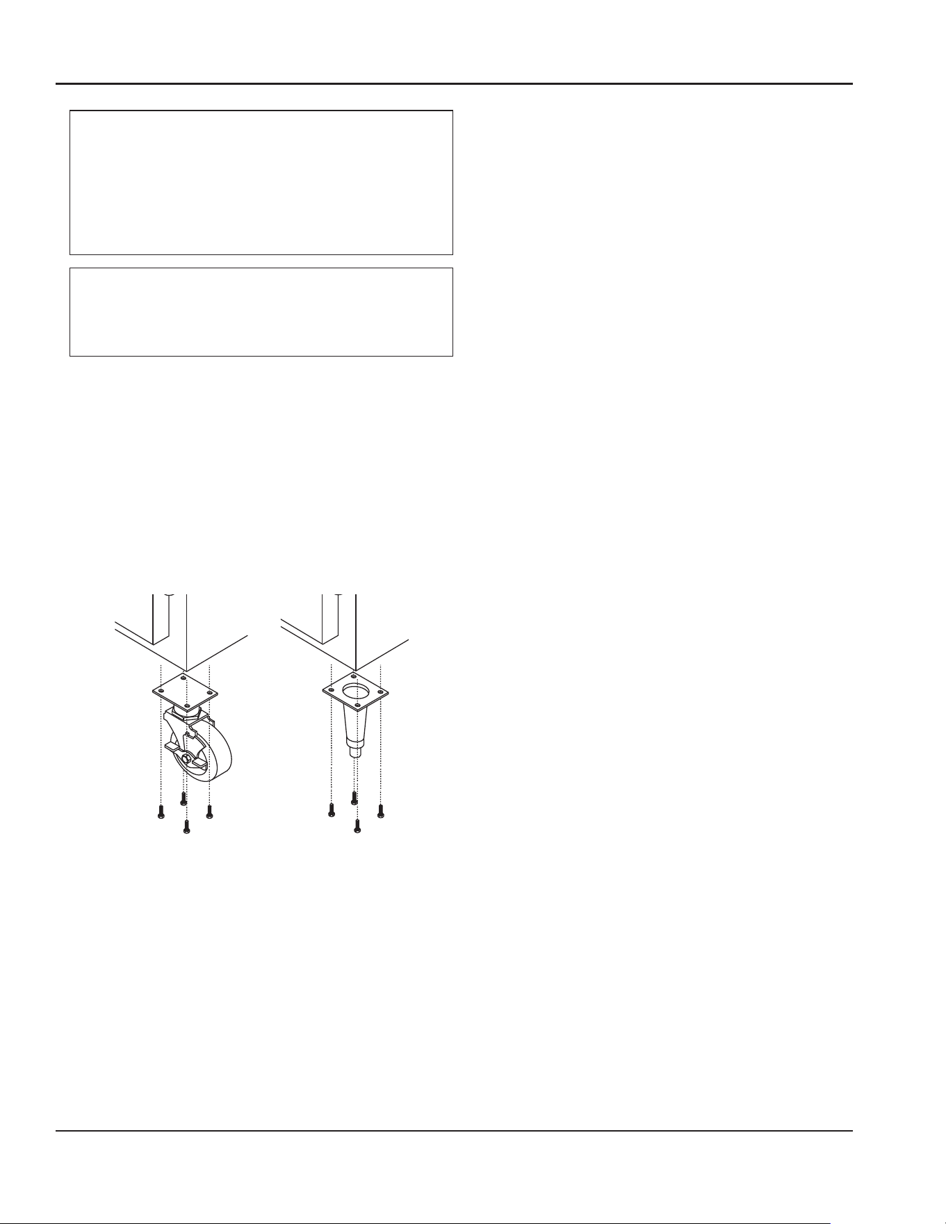
Leg & Caster Installation
DANGER
Legs or casters must be installed and the legs or casters
must be screwed in completely to prevent bending.
When casters are installed the mass of this unit will
allow it to move uncontrolled on an inclined surface.
These units must be tethered/secured to comply with
all applicable codes.
n
Warning
The unit must be installed in a stable condition with
the front wheels locked. Locking the front casters after
installation is the owner’s and operator’s responsibility.
n
Warning
Single Section models with glass doors or drawers are
supplied with flanged feet that must be fastened to the
floor to prevent the unit from tipping when the door/
drawer(s) are opened.
Installation Section 2
12 Part Number: 9294254 01/23
n
Warning
Use a jack to lift the refrigeration unit off the ground
just far enough to remove the leg/caster. Place blocking
underneath the unit. Do not work underneath a raised
unit without proper blocking. Do not lift the unit more
than necessary to remove the leg/caster. Lifting the unit
too far can make the unit unstable.
,
Caution
All single-section units require that the swivel casters be
mounted on the front and rigid casters be mounted on
the rear.
To install the legs or casters:
1. Remove unit from skid.
NOTE: The bolts used to hold the unit to the skid should
be re-used as the fourth hex head bolt for each caster
or leg plate installation. The bolt should not measure
over 2” (5cm) in length.
2. Raise unit to access leg/caster mounting holes on
bottom of unit.
3. Attach the legs or casters to bottom of cabinet using
hex head bolts.
Models Energy Use
in kWh
Refrigerators
1 Section
6025XL-G(H) 2.08
6025XL-S(H) 1.66
2 Section
6051XL-G(H) 3.18
6051XL-S(H) 2.91
Freezers
1 Section
6125XL-S(H) 5.78
2 Section
6151XL-S(H) 10.65
Model
BTU/Hour
Capacity
Heat of
Rejection
(BTU)
R290
Charge
1 Section Refrigerators
Glass
Full Height Doors
6025XL-G
1920 490 113g
Half Height Doors
6025XL-GH
1920 540 113g
Solid
Full Height Doors
6025XL-S
1920 385 113g
Half Height Doors
6025XL-SH
1920 400 113g
2 Section Refrigerators
Glass
Full Height Doors
6051XL-G
2540 780 113g
Half Height Doors
6051XL-GH
2540 880 113g
Solid
Full Height Doors
6051XL-S
2540 565 113g
Half Height Doors
6051XL-SH
2540 590 113g
1 Section Freezers
Solid
Full Height Doors
6125XL-S
2035 760 93g
Half Height Doors
6125XL-SH
2035 790 93g
2 Section Freezers
Solid
Full Height Doors
6151XL-S
2485 1275 109g
Half Height Doors
6151XL-SH
2485 1340 109g

Section 2 Installation
Part Number: 9294254 01/23 13
THIS PAGE INTENTIONALLY LEFT BLANK
Part Number: 9294254 01/23 14
DANGER
Do not operate any appliance with a damaged cord
or plug. All repairs must be performed by a qualified
service company.
DANGER
Never stand on the unit! They are not designed to
hold the weight of an adult, and may collapse or tip if
misused in this manner.
n
Warning
Do not contact moving parts.
n
Warning
All covers and access panels must be in place and
properly secured, before operating this equipment.
n
Warning
Do not use electrical appliances inside the food storage
compartment of this appliance.
n
Warning
The operator of this equipment is solely responsible
for ensuring safe holding temperature levels for all
food items. Failure to do so could result in unsafe food
products for customers.
n
Warning
Overloading shelves can damage equipment or cause
bodily injury.
n
Warning
Damp or wet hands may stick to cold surfaces.
n
Warning
Do not block the supply and return air grills or the air
space around the air grills. Keep plastic wrappings,
paper, labels, etc. from being airborne and lodging in
the grills. Failure to keep the air grills clear will result in
unsatisfactory operation of the system.
,
Caution
Do not throw items into the storage area. Failure to
heed this recommendation could result in damage to
the interior of the cabinet or to the blower coil.
R290 Controls/Programming/Settings
R290 Refrigerator
Refrigerators are factory set at mid-range to maintain about
38ºF (3ºC) box temperature.
1. At initial start-up or anytime power is disconnected,
then reconnected to the unit, the control will go into
defrost mode.
2. The control will enter a DEFROST mode and the display
will read dEF. The compressor and condenser fan as
well as the evaporator fan will remain off until this
initial defrost is complete. This initial defrost cycle may
take up to 35 minutes to complete.
3. The display will continue to read dEF for an additional
30 minutes while the cooling cycle cools the box to the
set temperature.
4. Then the digital thermostat will display box
temperature.
5. The temperature control will cycle the compressor,
evaporator fan motor and condenser fan motor to
maintain box temperature at the control setting. For
more information see R290 Evaporator Fan Operation
on page 16.
R290 Refrigerator Defrost
The temperature control also monitors the evaporator
temperature and will turn off the compressor and
condenser fan motor when needed to allow accumulated
frost on the evaporator to clear. During this defrost cycle,
the digital temperature display will read dEF. After the
defrost cycle is complete, the temperature control will
return to a normal cooling cycle, but the display will
continue to read dEF until the evaporator returns to normal
cooling temperatures (up to 30 minutes).
Section 3
Operation
Part Number: 9294254 01/23 15
Section 3 Operation
R290 Freezer
Freezers are factory set at mid-range to maintain about -2ºF
(-19ºC) box temperature.
1. At initial start-up or anytime power is disconnected,
then reconnected to the unit, the control will go into
defrost mode
2. The control will enter a DEFROST mode and the display
will read dEF. The compressor and condenser fan as
well as the evaporator fan will remain off until this
initial defrost is complete. This initial defrost cycle may
take up to 35 minutes to complete.
3. The display will continue to read dEF for an additional
30 minutes while the freezing cycle cools the box to the
set temperature.
4. Then the thermostat will display box temperature.
5. The temperature control will cycle the compressor,
evaporator fan motor and condenser fan motor to
maintain box temperature at the control setting. For
more information see R290 Evaporator Fan Operation
on page 16.
R290 Freezer Automatic Defrost
The control also monitors compressor total running time
and will enter a defrost cycle after total compressor running
time is greater than seven hours since the last defrost cycle
OR if evaporator coil temperature drops below -30ºF (-34ºC)
(indicating excessive frost on the coil).
R290 Freezer Manual Defrost
If a manual defrost is desired, hold the upper left button for
five seconds or unplug the unit for several seconds, then
plug unit back in. This will cause the control to re-initialize
and then enter a defrost cycle.
When the control enters the defrost mode, it switches off
the evaporator fan motor, compressor and condenser fan
motor, and switches on the defrost heater to warm the
evaporator coil. Thereby melting all frost accumulated
during the previous refrigeration cycle. The digital
temperature display will now read dEF. The control will
continue the defrost cycle for a MINIMUM of six minutes
and a MAXIMUM of 35 minutes depending on the amount
of frost accumulated on the evaporator coil.
After the defrost cycle is complete, the control returns
to a normal refrigeration cycle, however the evaporator
fan motor will not switch on until the evaporator reaches
-5°F (-21°C) or two minutes AFTER the compressor and
condenser fan motor have begun operating. The digital
temperature display will continue to read dEF until the
evaporator has returned to normal freezing temperatures
(up to 30 minutes).
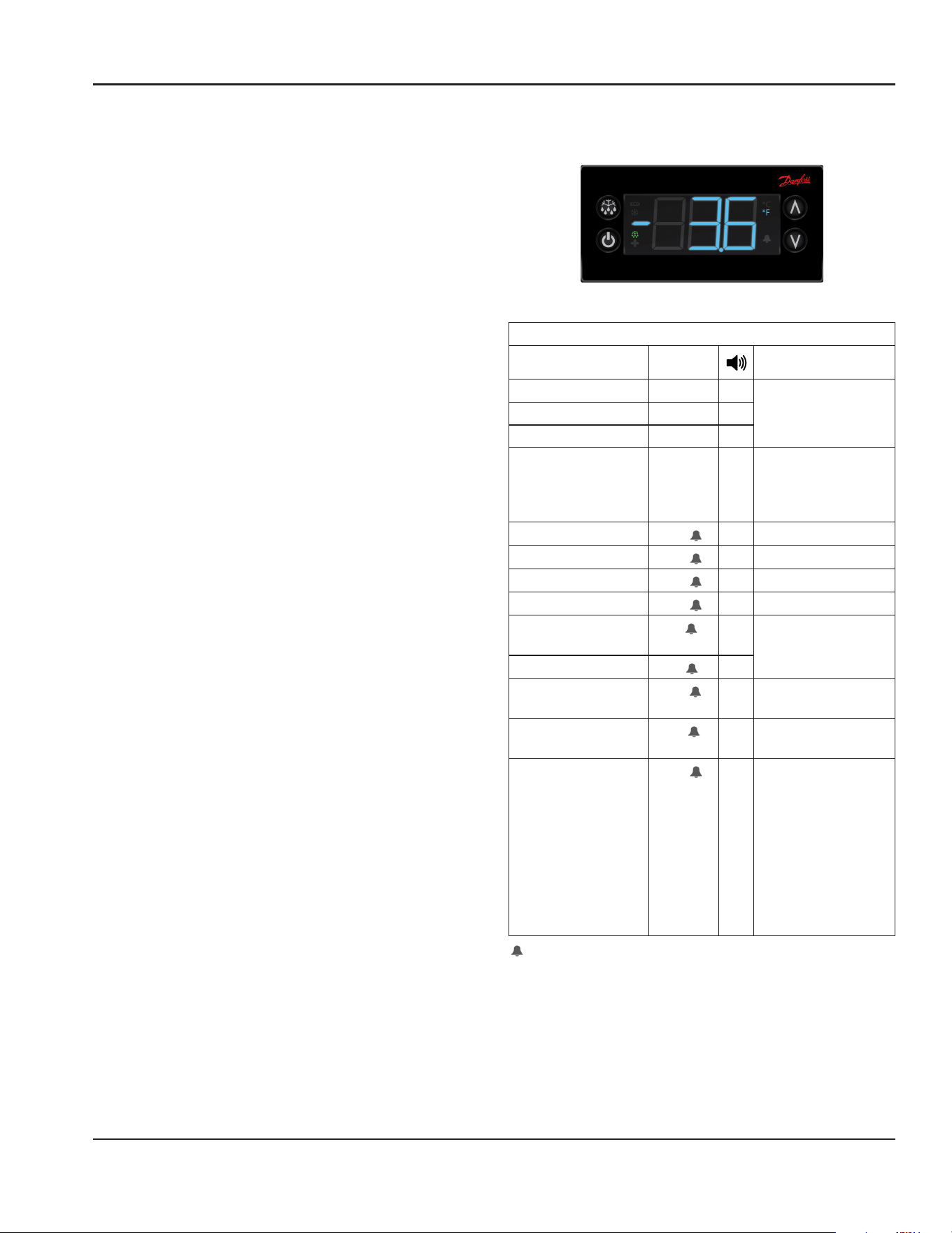
CONTROL & DISPLAY
R290 TEMPERATURE CONTROL & DISPLAY
Control Display
Operation / Indication
Status Displayed Comments
Normal (°C) Temp. [°C] Unit depends on setting
(parameters in control)
Normal (°F) Temp. [°F]
Show set-point Temp.
Set to Defrost dEF / Temp Depends on setting
(parameters in control
or as chosen by upper
left button)
Sensor 1 defect
E01
X Air sensor
Sensor 2 defect
E02
X Coil sensor
Sensor 3 defect
E03
X Open
Sensor 4 defect
E04
X Open
High temperature
alarm
Hi
X Automatically switching
at 2 sec rate
Low temperature alarm
Lo
X
Line voltage too high,
above 140 volts
uHi
X
Line voltage too low,
below 96 volts
uLi
X
Control calls for cooling
for more than 24 hours
straight
LEA
X Time includes defrost.
Error will go away if the
control cycles off the
compressor or if the
power is shut off. If error
is on a cold pan it could
be related to a high
ambient temperature or
not shutting the rail off
nightly.
All alarms sound for approximately 10 seconds and then
are silent for 50 seconds. It will do that for 15 cycles and
then remain silent. The alarm code will still be present on
the display until the fault clears.
Operation Section 3
16 Part Number: 9294254 01/23
R290 Temperature Control & Display Operation
Press upper or lower right button.
• Display show actual set-point (blinking).
» If buttons untouched for 3 seconds returns to normal.
• Increase set-point by pressing upper button. Max value
depends on parameters in control.
• Decrease set-point by pressing lower button. Min value
depends on parameters in control.
» If buttons untouched for 3 seconds returns to normal
and stores new set-point.
Press upper left button for 5 seconds.
• Start defrost.
Press lower left button for 5 seconds.
• Unit goes into stand-by mode.
» The display will read off, then a period.
• Press the lower left button again for 5 seconds.
» The display will read on.
» The unit will then start up in the defrost mode, and
display will read dEF.
R290 Power Switch
All freezers and refrigerators are equipped with a power
disconnect switch located behind the louvered end panel.
Switch must be in the on position for the unit to operate. If
the switch is turned off, then returned to the on position,
the unit will enter a defrost cycle and the display will read
dEF.
R290 Energy Saver Switch
Select freezers are equipped with an energy saver switch
for service use. It is located in the electrical box behind
the front shroud. It controls the length of time that heat
is applied to the door perimeter. The normal operating
position for this switch is the on position, providing the
shortest amount of time. If excessive condensation is
observed on the door opening, switch to the off position
with the help of an authorized service agent. The off
position will increase the length of time the door heater is
on.
R290 Temperature Alarm
The alarm will sound and flash “HI” or “LO” 90 minutes after
the unit has reached its alarm temperature point or after
any power interruption if the temperature is above or
below the alarm set points. Refrigerators are factory set at
mid-range to maintain about 38ºF (3ºC) box temperature.
The high refrigerator temperature point is 50°F (10°C). The
low refrigerator temperature point is 25°F (-4°C). Freezers
are factory set at mid-range to maintain about -2ºF (-19ºC)
box temperature. The high freezer temperature point is 20°F
(-7°C). Freezers do not have a low temperature point.
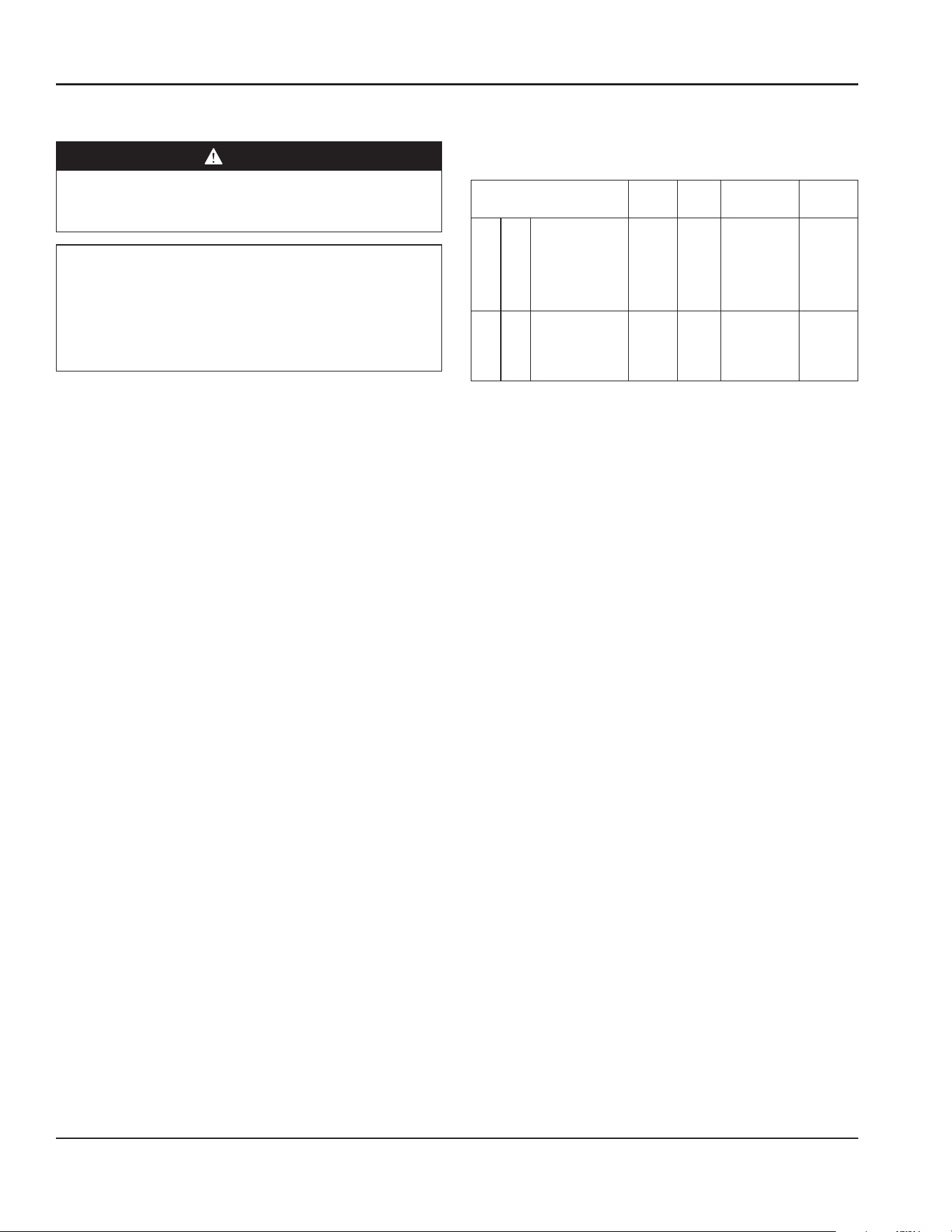
R290 EVAPORATOR FAN OPERATION
Depending on the units requirements, units may have
evaporator fans that run continually or cycle on and off
when power is applied. If you have a unit that you notice
the fan is cycling, please see the operations sequence
below.
During normal operation the evaporator fan may cycle
and/or pulse independently of the compressor. Consult
Technical Support at 1-844-724-CARE if you are unsure of
the proper function.
Cooling Cycle Defrost Cycle
Compressor
On
Compressor
Off
Compressor
Off
Evap Fan
On
Evap Fan
Off
Evap Fan
On
Evap Fan
Off
Evap Fan
On
Evap Fan
Off
Refrigerator X Cycles On 2-Min,
Off 2-Min
X
Freezer X X X
Part Number: 9294254 01/23 17
Section 3 Operation
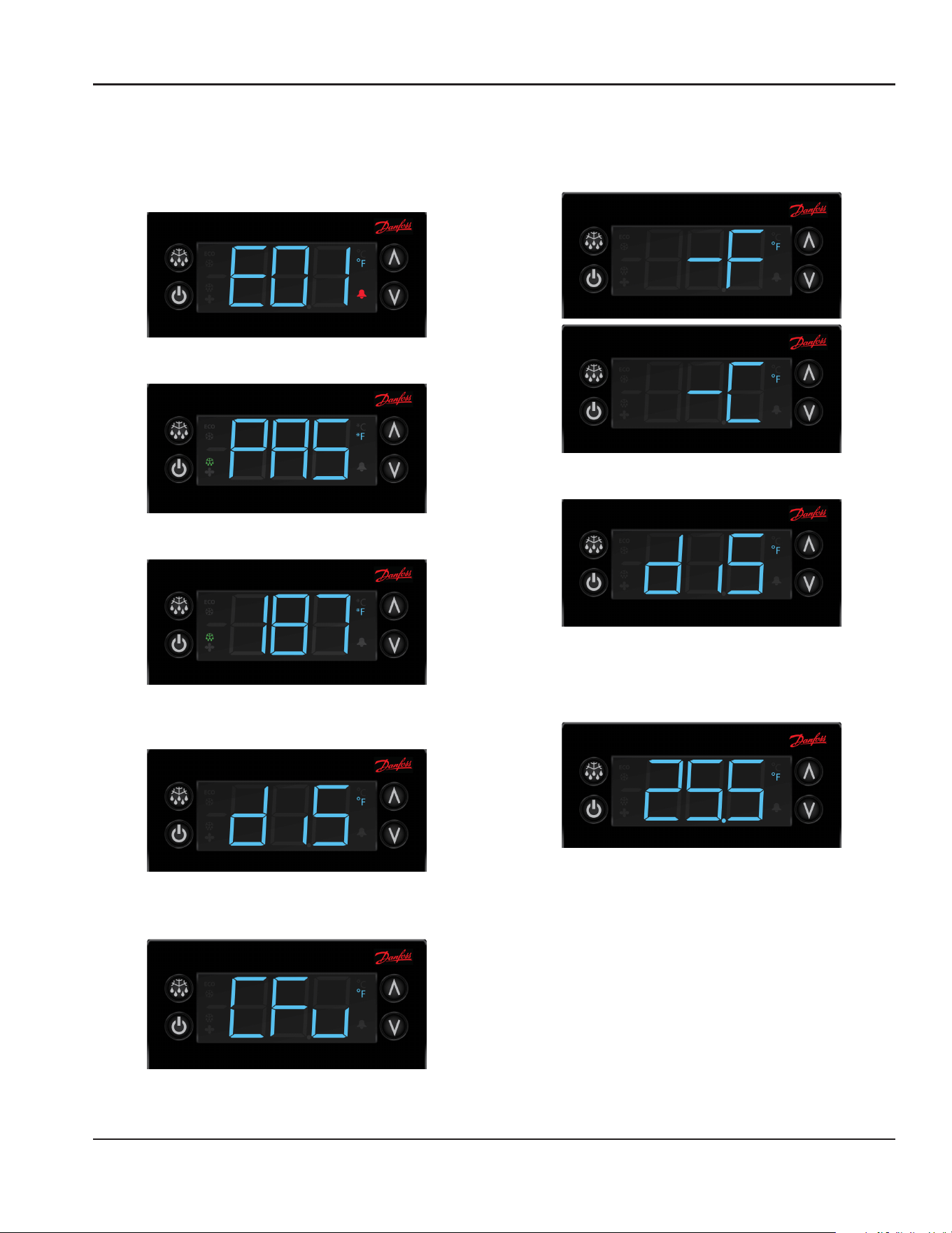
R290 CHANGING DISPLAY FROM FAHRENHEIT TO
CELSIUS ON ERC112 CONTROL
1. Simultaneously hold the up and down arrows for
5 seconds to access menu for password protected
parameters.
2. Screen should temporarily flash PAS and then move to
a numeric screen.
3. Scroll to 187 using the up/down arrows and push the
stand-by button (lower left button) to enter.
4. Scroll to dis using the up/down arrows and push the
stand-by button (lower left button) to enter into the
display menu.
5. Scroll to CFu using the up/down arrows and push the
stand-by button (lower left button) to enter the display
unit menu.
6. -F should be displayed indicating Fahrenheit. Use
the down arrow to change it to -C for Celsius and hit
the stand-by button (lower left button) to enter the
change.
7. Push the defrost button (upper left button) to move
out of the display unit menu.
8. Push the defrost button (upper left button) to move
out of the display menu and back to the normal display.
NOTE: For steps 7 and 8, display will return back to normal
display after 30 seconds of inactivity.

Operation Section 3
18 Part Number: 9294254 01/23
THIS PAGE INTENTIONALLY LEFT BLANK
Part Number: 9294254 01/23 19
Section 4
Maintenance
DANGER
It is the responsibility of the equipment owner to
perform a Personal Protective Equipment Hazard
Assessment to ensure adequate protection during
maintenance procedures.
DANGER
Failure to disconnect the power at the main power
supply disconnect could result in serious injury or death.
The power switch DOES NOT disconnect all incoming
power.
DANGER
Disconnect electric power at the main power disconnect
for all equipment being serviced. Observe correct
polarity of incoming line voltage. Incorrect polarity can
lead to erratic operation.
n
Warning
Never use sharp objects or tools to remove ice or frost.
Do not use mechanical devices or other means to
accelerate the defrosting process.
Cleaning and Sanitizing Procedures
,
Caution
Maintenance and servicing work other than cleaning as
described in this manual must be done by an authorized
service personnel.
GENERAL
n
Warning
When using cleaning fluids or chemicals, rubber gloves
and eye protection (and/or face shield) must be worn.
You are responsible for maintaining the equipment
in accordance with the instructions in this manual.
Maintenance procedures are not covered by the warranty.
Maintenance Daily Weekly Monthly
After Prolonged
Shutdown
At Start-Up
Interior X X X
Gasket X X X
Exterior X X X
Drain X X X
Condenser Coil X X X
Casters X X X

20 Part Number: 9294254 01/23
Maintenance Section 4
INTERIOR CLEANING
Notice
When cleaning interior and exterior of unit, care should
be taken to avoid the front power switch and the rear
power cord. Keep water and/or cleaning solutions away
from these parts.
Notice
Never use a high-pressure water jet for cleaning or hose
down or flood interior or exterior of units with water. Do
not use power cleaning equipment, steel wool, scrapers
or wire brushes on stainless steel or painted surfaces.
The interior can be cleaned using soap and warm water. If
this isn’t sufficient, try ammonia and water or a nonabrasive
liquid cleaner.
EXTERIOR CLEANING
Notice
Never use an acid based cleaning solution on exterior
panels! Many food products have an acidic content,
which can deteriorate the finish. Be sure to clean the
stainless steel surfaces of ALL food products.
Clean the area around the unit as often as necessary to
maintain cleanliness and efficient operation.
Wipe gasket and surfaces with a damp cloth rinsed in water
to remove dust and dirt from the outside of the unit. Always
rub with the “grain” of the stainless steel to avoid marring
the finish. If a greasy residue persists, use a damp cloth
rinsed in a mild dish soap and water solution. Wipe dry with
a clean, soft cloth.
Never use steel wool or abrasive pads for cleaning. Never
use chlorinated, citrus based or abrasive cleaners.
Stainless steel exterior panels have a clear coating that
is stain resistant and easy to clean. Products containing
abrasives will damage the coating and scratch the panels.
Daily cleaning may be followed by an application of
stainless steel cleaner which will eliminate water spotting
and fingerprints. Early signs of stainless steel breakdown
are small pits and cracks. If this has begun, clean thoroughly
and start to apply stainless steel cleaners in attempt to
restore the steel.

Part Number: 9294254 01/23 21
Section 4 Maintenance
DRAIN
Each unit has a drain located inside the unit that removes
the condensation from the evaporator coil and routes it
to an external condensate evaporator pan. Each drain can
become loose or disconnected during normal use. If you
notice water accumulation on the inside of the unit, be sure
the drain tube is connected to the evaporator drain pan.
If water is collecting underneath the unit, make sure the
end of the drain tube is in the condensate evaporator. The
leveling of the unit is important as the units are designed to
drain properly when level. Be sure all drain lines are free of
obstructions.
CLEANING THE CONDENSER COIL
In order to maintain proper refrigeration performance, the
condenser fins must be cleaned of dust, dirt and grease
regularly. It is recommended that this be done monthly. If
conditions are such that the condenser is totally blocked
in a month, the frequency of cleaning should be increased.
Clean the condenser with a vacuum cleaner or stiff brush. If
extremely dirty, a commercially available condenser cleaner
may be required.
Failure to maintain a clean condenser coil can initially cause
high temperatures and excessive run times. Continuous
operation with a dirty or clogged condenser coil can
result in compressor failure. Neglecting the condenser coil
cleaning procedures will void any warranties associated
with the compressor and cost to replace the compressor.
CASTERS
Wipe casters with a damp cloth monthly to prevent
corrosion.
DOORS/HINGES
Over time and with heavy-use doors, the hinges may
become loose. If this happens, tighten the screws that
mount the hinge brackets to the frame of the unit. Loose
or sagging doors can cause the hinges to pull out of the
frame, which may damage both the doors and the hinges.
In some cases this may require qualified service agents or
maintenance personnel to perform repairs.
PREVENTING BLOWER COIL CORROSION
To help prevent corrosion of the blower coil, store all acidic
items, such as pickles and tomatoes, in seal-able containers.
Immediately wipe up all spills.

22 Part Number: 9294254 11/17
Troubleshooting Section 5
THIS PAGE INTENTIONALLY LEFT BLANK
Section 5
Troubleshooting

Part Number: 9294254 11/17 23
Section 5 Troubleshooting
THIS PAGE INTENTIONALLY LEFT BLANK
DELFIELD
980 SOUTH ISABELLA ROAD, MOUNT PLEASANT, MI 48858
800-733-8821
WWW.DELFIELD.COM
©2019 Welbilt Inc. except where explicitly stated otherwise. All rights reserved.
“Part Number 9294254 01/23