Owner’s Manual
IMPORTANT NOTE:
SKU:ZX-DH-22-AZ-HM / ZX-DH-35-AZ-HM / ZX-DH-50-AZ-HM
Before using your appliance, please read this manual carefully and keep it for future reference.
EN
DEHUMIDIFIER

CONGRATULATIONS
Dear Customer:
Welcome to our family. Thank you for purchasing one of our products.
Our goal is to provide you with superior service. If there is anything missing from or wrong with your order,
or if you have any questions about using our Dehumidifier, PLEASE contact us.
Email: [email protected]
Our team is available 24/7 to address your questions, comments, and concerns. Your satisfaction is our
ultimate goal. We want to make everything right so you'll share your positive experience with other shoppers
on Amazon.
If you experience any problems, please send an email to [email protected].

Technical Parameters
07-09
10-14
18-21
24
Troubleshooting
25
Warranty And Service
26
CONTENTS
Safety precautions
01-06
Safety manual for R32 refrigerant model
15-17
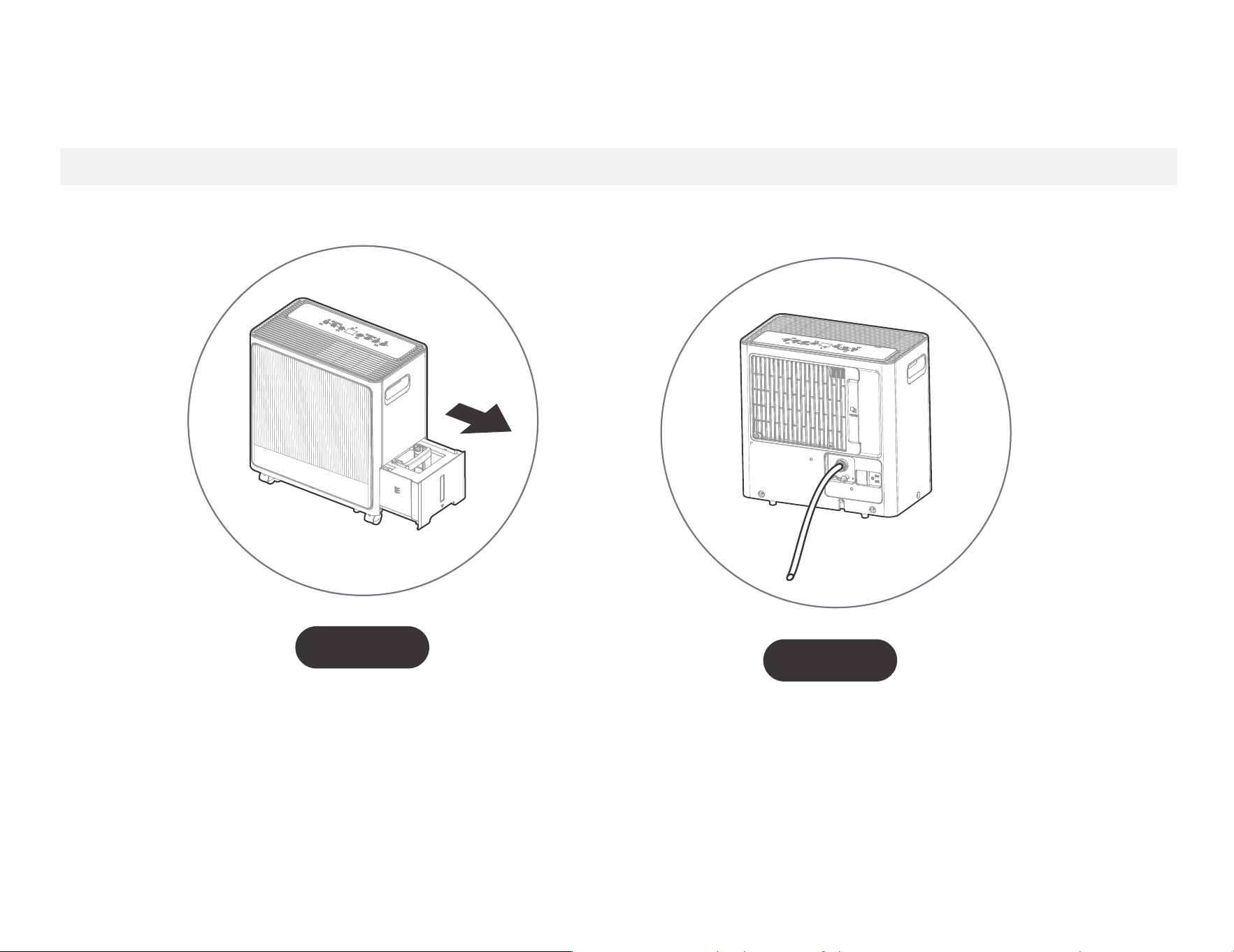
Dump the collected water
Get to know your product
Dump the collected water
Get to know your product
Get to know your features
Care and Maintenance
22-23
Safety manual for R32
refrigerant model
01
CAUTION:
Risk of fire
flammable materials
IMPORTANT NOTE: Read this manual
carefully before installing or operating
your new appliance unit. Make sure
to save this manual for future reference.
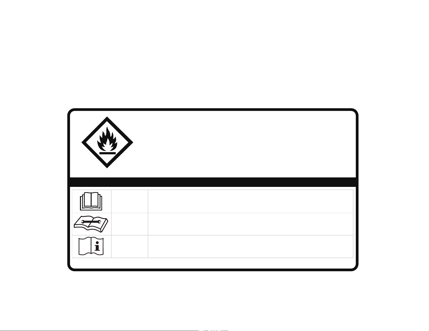
Explanation of symbols displayed on the unit
CAUTION
This symbol shows that the operation manual should be read carefully.
CAUTION
This symbol shows that a service personnel should be handling this equipment with
reference to the installation manual.
CAUTION
This symbol shows that information is available such as the operating manual or
installation manual.
North America Products
SAFETY MANUAL(R32)A 20231108
16120300001219
A2L

02
-Servicing shall only be performed as recommended by the
equipment manufacturer. Maintenance and repair requiring the
assistance of other skilled personnel shall be carried out under the
supervision of the person competent in the use of flammable
refrigerants.
-DO NOT modify the length of the power cord or use an extension
cord to power the unit.
-DO NOT share a single outlet with other electrical appliances.
Improper power supply can cause fire or electrical shock.
-Please follow the instruction carefully to handle, install, clear,
service the appliance to avoid any damage or hazard.
Flammable
Refrigerant R32 is used within appliance.
-When maintaining or disposing the appliance, the refrigerant
(R32) shall be recovered properly, shall not discharge to air directly.
-Compliance with national gas regulations shall be observed.
-Keep ventilation openings clear of obstruction.
-The appliance shall be stored so as to prevent mechanical damage
from occurring.
-A warning that the appliance shall be stored in a well-ventilated
area where the room size corresponds to the room area as
specified for operation.
-Any person who is involved with working on or breaking into a
refrigerant circuit should hold a current valid certificate from an
industry-accredited assessment authority, which authorises their
competence to handle refrigerants safely in accordance with an
industry recognised assessment specification.
Examples for such working procedures are:
• breaking into the refrigerating circuit;
• opening of sealed components;
• opening of ventilated enclosures.
-No any open fire or device like switch which may generate
spark/arcing shall be around appliance to avoid causing
ignition of the flammable refrigerant used. Please follow the
instructions carefully when storing or maintaining the appliance to
prevent mechanical damage from occurring.
-Do not use means to accelerate the defrosting process or to clean,
other than those recommended by the manufacturer.
-The appliance shall be stored in a room without continuously
operating ignition sources (for example: open flames, an operating
gas appliance) and ignition sourcesor (for example: an operating
electric heater) close to the appliance.
-Do not pierce or burn.
-Be aware that the refrigerants may not contain an odour.
AVERTISSEMENT
Ne pas utiliser de produits permettant d accélérer le dégel ou de
produits de nettoyage autres que ceux recommandés par le
fabricant.
L’appareil doit être entreposé dans un endroit sans source d
allumage fonctionnant en continu (par exemple : flamme nue,
appareil au gaz en marche ou radiateur électrique en marche).
Ne pas percer ni bruler. Attention : les frigorigènes peuvent être
inodores.
1.Transport of equipment containing flammable refrigerants
See transport regulations.
2.Marking of equipment using signs
See local regulations.
3.Disposal of equipment using flammable refrigerants
See national regulations.
4.Storage of equipment/appliances
The storage of equipment should be in accordance with the
manufacturer's instructions.
5.Storage of packed (unsold) equipment
Storage package protection should be constructed such that
mechanical damage to the equipment inside the package will not
cause a leak of the refrigerant charge. The maximum number of
pieces of equipment permitted to be stored together will be
determined by local regulations.
6.Information on servicing
WARNING:

03
1)Checks to the area
Prior to beginning work on systems containing flammable
refrigerants, safety checks are necessary to ensure that the risk of
ignition is minimised. For repair to the refrigerating system, the
following precautions shall be complied with prior to conducting
work on the system.
2)Work procedure
Work shall be undertaken under a controlled procedure so as to
minimise the risk of a flammable gas or vapour being present while
the work is being performed.
3)General work area
All maintenance sta� and others working in the local area shall be
instructed on the nature of work being carried out. Work in
confined spaces shall be avoided. The area around the workspace
shall be sectioned o�. Ensure that the conditions within the area
have been made safe by control of flammable material.
4)Checking for presence of refrigerant
The area shall be checked with an appropriate refrigerating
detector prior to and during work, to ensure the technician is aware
of potentially flammable atmospheres. Ensure that the leak
detection equipment being used is suitable for use with flammable
refrigerants, i.e. non-sparking, adequately sealed or intrinsically safe.
5)Presence of fire extinguisher
If any hot work is to be conducted on the refrigeration equipment
or any associated parts, appropriate fire extinguishing equipment
shall be available to hand. Have a dry powder or CO2 fire
extinguisher adjacent to the charging area.
6)No ignition sources
No person carrying out work in relation to a refrigerating system
which involves exposing any pipe work that contains or has
contained flammable refrigerant shall use any sources of ignition in
such a manner that it may lead to the risk of fire or explosion. All
possible ignition sources, including cigarette smoking, should be
kept su�ciently far away from the site of installation, repairing,
removing and disposal, during which flammable refrigerant can
possibly be released to the surrounding space. Prior to work taking
place, the area around the equipment is to be surveyed to make
sure that there are no flammable hazards or ignition risks. No
Smoking signs shall be displayed.
7)ventilated area
Ensure that the area is in the open or that it is adequately ventilated
before breaking into the system or conducting any hot work. A
degree of ventilation shall continue during the period that the work
is carried out. The ventilation should safely disperse any released
refrigerant and preferably expel it externally into the atmosphere.
8)Checks to the refrigerating equipment
Where electrical components are being changed, they shall be fit
for the purpose and to the correct specifications. At all times the
manufacturer's maintenance and service guidelines shall be
followed. If in doubt consult the manufacturer's technical
department for assistance. The following checks shall be applied to
installations using flammable refrigerants: the actual refrigerant
charge is in accordance with the room size within which the
refrigerant containing parts are installed; the ventilation machinery
and outlets are operating adequately and are not obstructed; if an
indirect refrigerating circuit is being used, the secondary circuit shall
be checked for the presence of refrigerant; marking to the
equipment continues to be visible and legible. markings and signs
that are illegible shall be corrected; and refrigerating pipe or
components are installed in a position where they are unlikely to be
exposed to any substance which may corrode refrigerant containing
components, unless the components are constructed of materials
which are inherently resistant to being corroded or are suitably
protected against being so corroded.
9)Checks to electrical devices
Repair and maintenance to electrical components shall include
initial safety checks and component inspection procedures. If a
fault exists that could compromise safety, then no electrical
supply shall be connected to the circuit until it is satisfactorily
dealt with. If the fault cannot be corrected immediately but it is
necessary to continue operation, an adequate temporary solution
shall be used. This shall be reported to the owner of the
equipment so all parties are advised.
Initial safety checks shall include:
That capacitors are discharged: this shall be done in a safe
manner to avoid possibility of sparking; that there no live
electrical components and wiring are exposed while charging,
recovering or purging the system; that there is continuity of
earth bonding.

04
7.Sealed electrical components shall be replaced.
1)During repairs to sealed components, all electrical supplies shall
be disconnected from the equipment being worked upon prior to
any removal of sealed covers, etc. If it is absolutely necessary to
have an electrical supply to equipment during servicing, then a
permanently operating form of leak detection shall be located at
the most critical point to warn of a potentially hazardous situation.
2)Particular attention shall be paid to the following to ensure that by
working on electrical components, the casing is not altered in such
a way that the level of protection is affected.
Check for damage to cables, excessive number of
connections, terminals not made to original specification, damage
to seals, incorrect fitting of glands, etc.
Ensure that apparatus is mounted securely.
Ensure that seals or sealing materials have not degraded such that
they no longer serve the purpose of preventing the ingress of
flammable atmospheres. Replacement parts shall be in accordance
with the manufacturer's specifications.
NOTE: The use of silicon sealant may inhibit the effectiveness of
some types of leak detection equipment. Intrinsically safe
components do not have to be isolated prior to working on them.
8.Intrinsically safe components must be replaced.
Do not apply any permanent inductive or capacitance loads to the
circuit without ensuring that this will not exceed the permissible
voltage and current permitted for the equipment in use.
Intrinsically safe components are the only types that can be
worked on while live in the presence of a flammable atmosphere.
The test apparatus shall be at the correct rating. Replace
components only with parts specified by the manufacturer. Other
parts may result in the ignition of refrigerant in the atmosphere
from a leak.
9.Cabling
Check that cabling will not be subject to wear, corrosion,
excessive pressure, vibration, sharp edges or any other adverse
environmental effects. The check shall also take into account the
effects of aging or continual vibration from sources such as
compressors or fans.
10.Detection of flammable refrigerants
Under no circumstances shall potential sources of ignition be
used in the searching for or detection of refrigerant leaks. A
halide torch (or any other detector using a naked flame) shall
not be used.
The following leak detection methods are deemed acceptable for
systems containing flammable refrigerants. Electronic leak
detectors shall be used to detect flammable refrigerants, but the
sensitivity may not be adequate, or may need re-calibration.
(Detection equipment shall be calibrated in a refrigerant-free area.)
Ensure that the detector is not a potential source of ignition and is
suitable for the refrigerant used. Leak detection equipment shall be
set at a percentage of the LFL of the refrigerant and shall be
calibrated to the refrigerant employed and the appropriate
percentage of gas (25% maximum) is confirmed. Leak detection
fluids are suitable for use with most refrigerants but the use of
detergents containing chlorine shall be avoided as the chlorine
may react with the refrigerant and corrode the copper pipe-work.
If a leak is suspected, all naked flames shall be
removed/extinguished. If a leakage of refrigerant is found which
requires brazing, all of the refrigerant shall be recovered from the
system, or isolated (by means of shut off valves) in a part of the
system remote from the leak. Removal of refrigerant shall be
according to Removal and evacuation.
11.Removal and evacuation
When breakin rant circuit to make repairs—or for
any other purpose - conventional procedures shall be used. However,
for flammable refrigerants it is important that best practice be
followed, since flammability is a consideration. The following
procedure shall be adhered to:
-Safely remove refrigerant following local and national regulations;
-Evacuate;
-Purge the circuit with inert gas (optional for A2L);
-Evacuate (optional for A2L);
-continuously flush or purge with inert gas when using flame to
open circuit; and
-open the circuit.

05
The refrigerant charge shall be recovered into the correct recovery cylinders if venting is not allowed by local and national codes. For
appliances containing flammable refrigerants, the system shall be purged with oxygen-free n flammable refrigerants. This process might
Compressed air or oxygen shall not be used for purging refrigerant systems.
For appliances containing flammable refrigerants, refrigerants purging shall be achieved by breaking the vacuum in the system with
oxygen-free nitrogen and continuing to fill until the working pressure is achieved, then venting to atmosphere, and finally pulling down
to a vacuum (optional for A2L). This process shall be repeated until no refrigerant is within the system (optional for A2L). When the final
oxygen-free nitrogen charge is used. the system shall be vented down to atmospheric pressure to enable work to take place.
The outlet for the vacuum pump shall not be close to any potential ignition sources, and ventilation shall be available.
12.Charging procedures
In addition to conventional charging procedures, the following requirements shall be followed. Ensure that contamination of di�erent
refrigerants does not occur when using charging equipment. Hoses or lines shall be as short as possible to minimise the amount of refrigerant
contained in them. Cylinders shall be kept in an appropriate position according to the instructions. Ensure that the refrigeration system is
earthed prior to charging the system with refrigerant. Label the system when charging is complete (if not already). Extreme care shall be
taken not to overfill the refrigeration system. Prior to recharging the system it shall be pressure tested with OFN. The system shall be leak
tested on completion of charging but prior to commissioning. A follow up leak test shall be carried out prior to leaving the site.
13.Decommissioning
Before carrying out this procedure, it is essential that the technician is completely familiar with the equipment and all its detail. It is
recommended good practice that all refrigerants are recovered safely. Prior to the task being carried out, an oil and refrigerant sample shall
be taken in case analysis is required prior to re-use of reclaimed refrigerant. It is essential that electrical power is available before the task is
commenced.
a)Become familiar with the equipment and its operation.
b)Isolate system electrically.
c)Before attempting the procedure ensure that: mechanical handling equipment is available, if required, for handling refrigerant cylinders;
all personal protective equipment is available and being used correctly; the recovery process is supervised at all times by a competent
person; recovery equipment and cylinders conform to the appropriate standards.
d)Pump down refrigerant system, if possible.
e)If a vacuum is not possible, make a manifold so that refrigerant can be removed from various parts of the system.
f)Make sure that cylinder is situated on the scales before recovery takes place.
g)Start the recovery machine and operate in accordance with instructions.
h)Do not overfill cylinders. (No more than 80% volume liquid charge.)
i)Do not exceed the maximum working pressure of the cylinder, even temporarily.
j)When the cylinders have been filled correctly and the process completed, make sure that the cylinders and the equipment are removed
from site promptly and all isolation valves on the equipment are closed o�.
k)Recovered refrigerant shall not be charged into another refrigeration system unless it has been cleaned and checked.
14.Labelling
Equipment shall be labelled stating that it has been de-commissioned and emptied of refrigerant. The label shall be dated and signed.
Ensure that there are labels on the equipment stating the equipment contains flammable refrigerant.

06
15.Recovery
When removing refrigerant from a system, either for servicing or decommissioning, it is recommended good practice that all refrigerants are
removed safely.
When transferring refrigerant into cylinders, ensure that only appropriate refrigerant recovery cylinders are employed. Ensure that the correct
number of cylinders for holding the total system charge is available. All cylinders to be used are designated for the recovered refrigerant and
labelled for that refrigerant (i.e., special cylinders for the recovery of refrigerant). Cylinders shall be complete with pressure-relief valve and
associated shut-off valves in good working order. Empty recovery cylinders are evacuated and, if possible, cooled before recovery occurs.
The recovery equipment shall be in good working order with a set of instructions concerning the equipment that is at hand and shall be
suitable for the recovery of the flammable refrigerant. If in doubt, the manufacturer should be consulted. In addition, a set of calibrated
weighing scales shall be available and in good working order. Hoses shall be complete with leak-free disconnect couplings and in good
condition.
The recovered refrigerant shall be processed according to local legislation in the correct recovery cylinder, and the relevant waste transfer
note arranged. Do not mix refrigerants in recovery units and especially not in cylinders.
If compressors or compressor oils are to be removed, ensure that they have been evacuated to an acceptable level to make certain that
flammable refrigerant does not remain within the lubricant. The compressor body shall not be heated by an open flame or other ignition
sources to accelerate this process. When oil is drained from a system, it shall be carried out safely.
Safety Precautions
WARNING
The signal word indicates a hazard with a medium level of risk which, if not avoided, may result in death
or serious injury.
CAUTION
The signal word indicates a hazard with a low degree of risk which, if not avoided, may result in minor or
moderate injury.
Explanation of Symbols
Must read the warning message.
07
Read Safety Precautions Before Operation and Installation To prevent death or injury to the user or other people and
property damage, the following instructions must be followed. Incorrect operation due to ignoring of instructions
may cause death, harm or damage.
WARNING
Do not exceed the rating of the power outlet or
connection device.
the power.
Do not damage or use an unspecified power cord.
Do not modify power cord length or share the outlet with
other appliances.
Do not insert or pull out plug with wet hands.
Do not install the appliance in a location that may be
exposed to combustible gas.
Do not place the unit near a heat source.
Disconnect the power if strange sounds, smell, or smoke
comes from it.
You should never try to take apart or repair the unit by
yourself.
Do not use the machine near flammable gas or
combustibles, such as gasoline, benzene, thinner, etc.
Do not drink or use the water drained from the unit.
Do not take the water bucket out during operation.
Do not use the unit in small spaces.
Do not put in places where water may splash onto
the unit.
WARNING
CAUTION
08
Place the unit on a level, sturdy section of the floor.
Do not cover the intake or exhaust openings with cloths
or towels.
Care should be taken when using the unit in a room with
the following persons: infants, children, elderly people,
and people not senstive to humidity.
Do not use in areas where chemicals are handled.
Never insert your finger or other foreign objects into
grills or openings. Take special care to warn children of
these dangers.
Prior to cleaning or other maintenance, the appliance
must be disconnected from the supply mains.
Do not install the appliance in a location that may be
exposed to combustible gas. If combustible gas
accumulates around the unit, it may cause fire.
unit and unplug it from the main power supply
immediately. Visually inspect the unit to ensure there is
no damage. If you suspect the unit has been damaged,
contact a technician or customer service for assistance.
If the supply cord is damaged, it must be replaced by the
manufacturer, its service agent or similarly qualied
persons in order to avoid a hazard.
This appliance is not intended for use by persons
(including childern) with reduced physical, sensory or
mental capabilities or lack of experience and knowledge,
unless they have been given supervision or instruction
concerning use of the appliance by a person responsible
for their safety.
Children should be supervised to ensure that they do not
play with the appliance.
Do not place heavy object on the power cord and take
care so that the cord is not compressed.
Do not climb up on or sit on the unit.
Always insert the filters securely. Clean filter once every
two weeks.
the power, contact a qualified service technician.
Do not place flower vases or other water container on
top of the unit.
Do not use extension cords.
Our product will not be used in a water damage
environment.
CAUTION
09
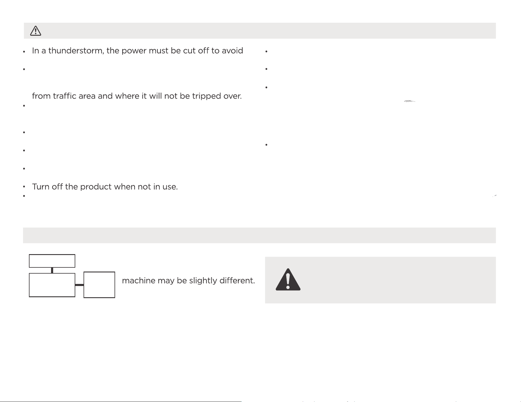
damage to the machine due to lightning.
Do not run cord under carpeting. Do not cover cord with
throw rugs, runners, or similar coverings. Do not route
cord under furniture or appliances. Arrange cord away
Do not operate unit with a damaged cord or plug.
Discard unit or return to an authorized service facility for
examination and/or repair.
To reduce the risk of fire or electric shock, do not use
this fan with any solid-state speed control device.
The appliance shall be installed in accordance with
national wiring regulations.
Contact the authorised service technician for repair or
maintenance of this unit.
The manufactures nameplate is located on the panel
of the unit and contains electrical and other technical
data specific to this unit.
Be sure the unit is properly grounded. To minimize
shock and fire hazards, proper grounding is important.
The power cord is equipped with a three-prong
grounding plug for protection against shock hazards.
Your unit must be used in a properly grounded wall
receptacle. If the wall receptacle you intend to use is not
adequately grounded or protected by a time delay fuse
or circuit breaker(please refer to the nameplate for the
electrical data), have a qualified electrician install the
proper receptacle.
The unit s circuit board(PCB) is designed with a fuse to
provide overcurrent protection.specifications of the fuse
are printed on the circuit board, such as:
T 3.15A/250V (or 350V), etc.
Electronic Work
NOTE: The cographs are for
explanation purpose only. Your
The actual shape shall prevail.
WARNING:
BEFORE PERFORMING ANY ELECTRICAL
OR WIRING WORK, TURN OFF THE MAIN
POWER TO THE SYSTEM.
DISPLAY
MAIN
CONTROL
POWER
SUPPLY
CORD
10
NOTE
All the illustrations in the manual
are for explanation purpose only.
Your machine may be slightly
prevail. The unit can be controlled
by the unit control panel.
1
2
3
4
5
6
7
8
9
10
11
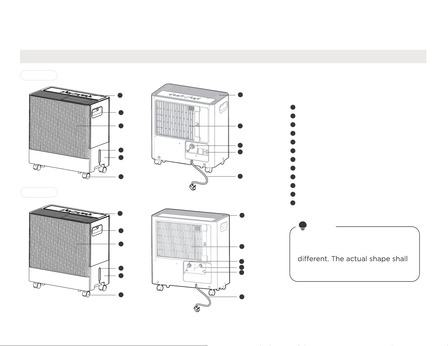
Control panel
Front panel
Water level window
Water bucket
Handle(both sides)
Air outlet grille
Continuous drain hose outlet
Power plug storage
Caster
Power cord and plug
12
Pump drainage(Pump model only)
Air filter (Air inlet grille)
Identification of parts
Model A
Model B
Get to know your product
Name of each component of the product
1
2
3
4
5
6
1
2
3
4
5
6
7
8
9
10
11
12
7
8
9
10
11
11
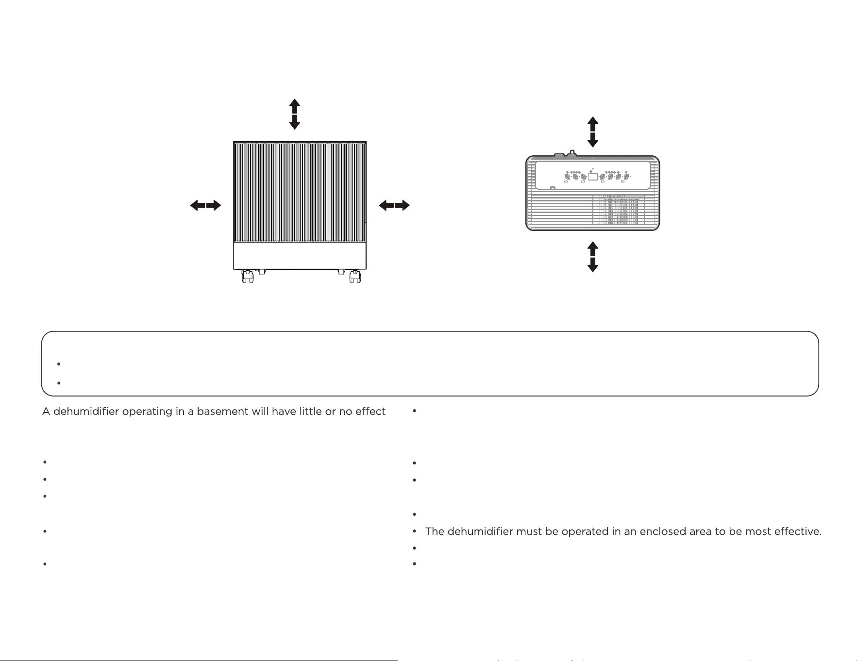
Positioning the unit
Casters(At four points on the bottom of unit)
Casters can move freely.
Do not force casters to move over carpet, nor move the unit with water in the bucket. (The unit may tip over and spill water.)
in drying an adjacent enclosed storage area, such as a closet, unless
there is adequate circulation of air in and out of the area.
Do not use outdoors.
This dehumidifer is intended for indoor residential applications only.
This dehumidifer should not be used for commercial or industrial
applications.
Place the dehumidifier on a smooth, level floor strong enough to
support the unit with a full bucket of water.
Allow at least 20cm of air space on all sides of the unit for good air
circulation (at least 40cm of air space on air outlet).
Place the unit in an area where the temperature will not fall below
5° C(41° F). The coils can become covered with frost at temperatures below
5° C(41° F), which may reduce performance.
Place the unit away from the clothes dryer, heater or radiator.
Use the unit to prevent moisture damage anywhere books or valuables are
stored.
Use the dehumidifier in a basement to help prevent moisture damage.
Close all doors, windows and other outside openings to the room.
20cm
or more
20cm
or more
Front view Top view
40cm
or more
40cm
or more
40cm
or more
Safe distance requirements
Before all tilting and moving operations, take out the bucket, open the
continuous drain outlet to empty the water, and disconnect the power cord.
When using your product
Preparations for product use.
•
When first using the dehumidifier, operate the unit continuously
24 hours. Ensure that the plastic cover is securely installed in continu-
ous dehumidification mode and does not leak.
When use in open space with open windows, condensation may
form on the surface of the product, which is normal.
quickly , allow approximately three minutes for the correct operation
to resume.
•
•
•
•
Do not connect the dehumidifier to a multiple socket
outlet, which is also being used for other electrical appliances.
Select a suitable location, making sure you have easy access to an
electrical outlet.
Plug the unit into a electrical socket-outlet with earth connection.
Make sure the Water bucket is correctly fitted otherwise the unit will
not operate properly.
•
•
NOTE
When the water in the bucket reaches to a certain level, please be careful to move the machine to avoid it falling down.
30%(RH) 80%(RH)
Operating TEMP.
Operating Humidity
Min.
Min.
Max.
Max.
5 C/41 F
32 C/90 F
3min
After a quick restart,
wait 3 minutes for the
operation to resume.
*Please refer to the actual
plug, and the legend is for
reference only.
Working condition requirement Precautions for use
Correct power connection Earth connection Proper installation of water tank
12
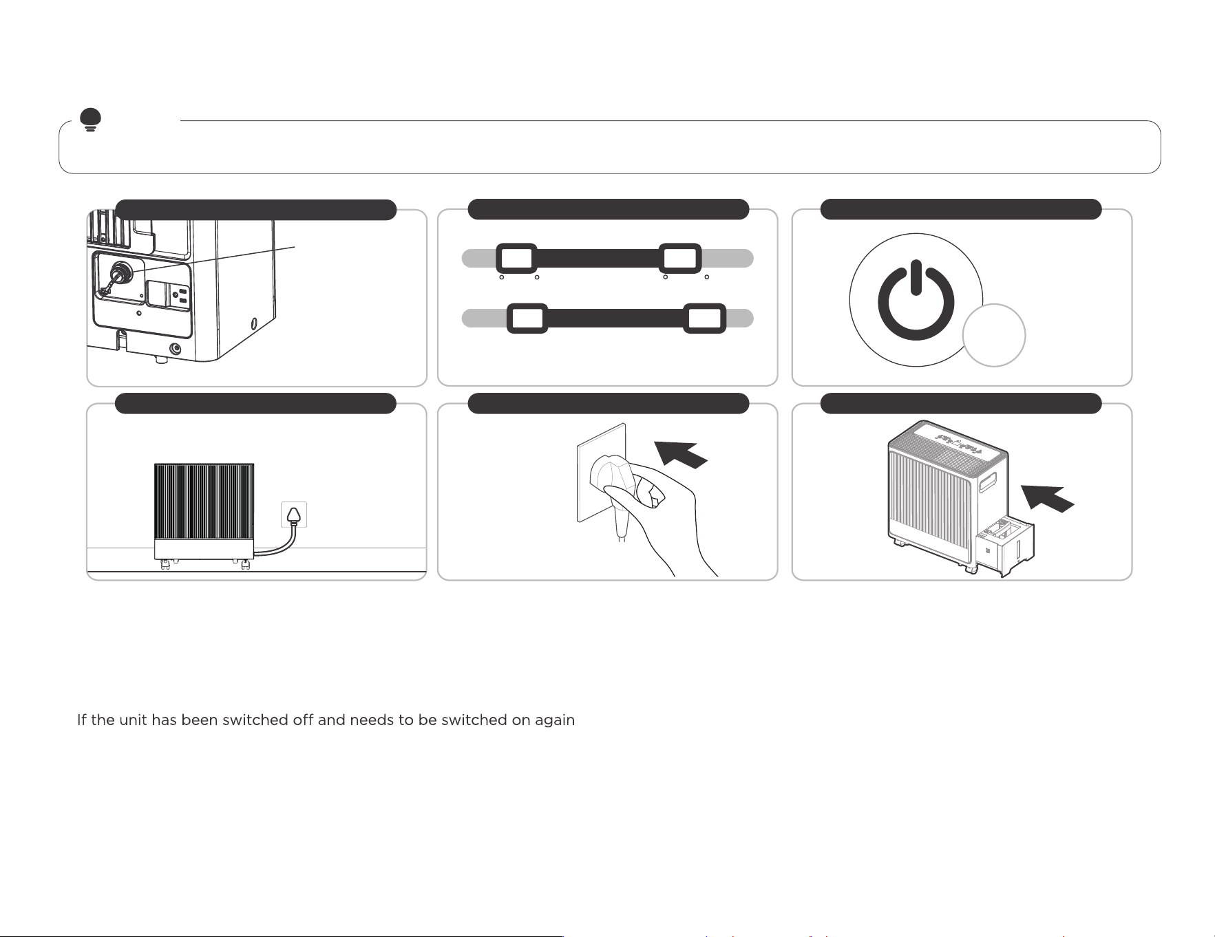
First time using
Ensure the water plug
is securely installed
and operate the unit
continuously 24 hours.
13
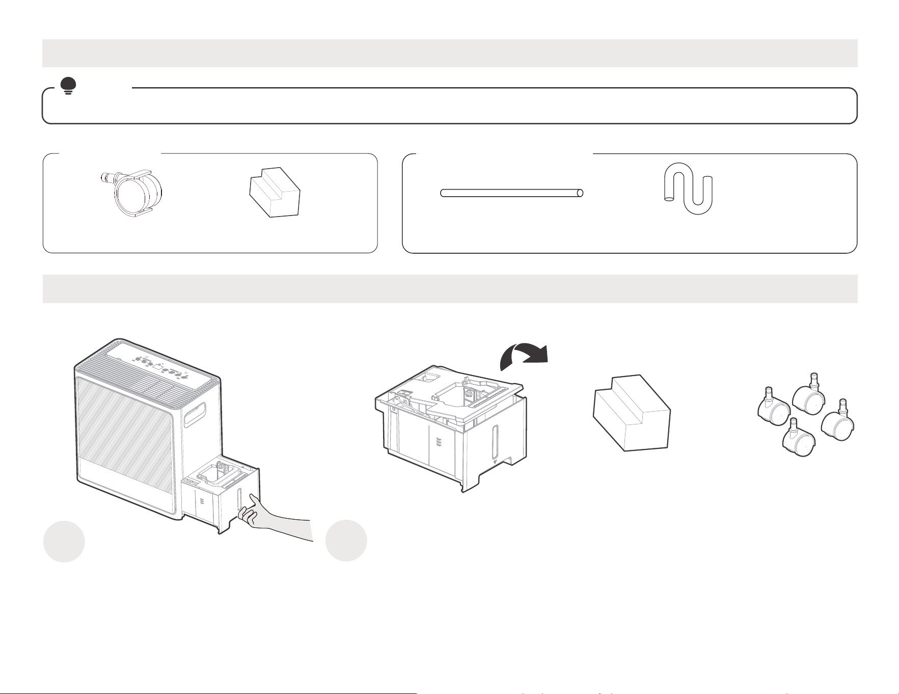
1
2
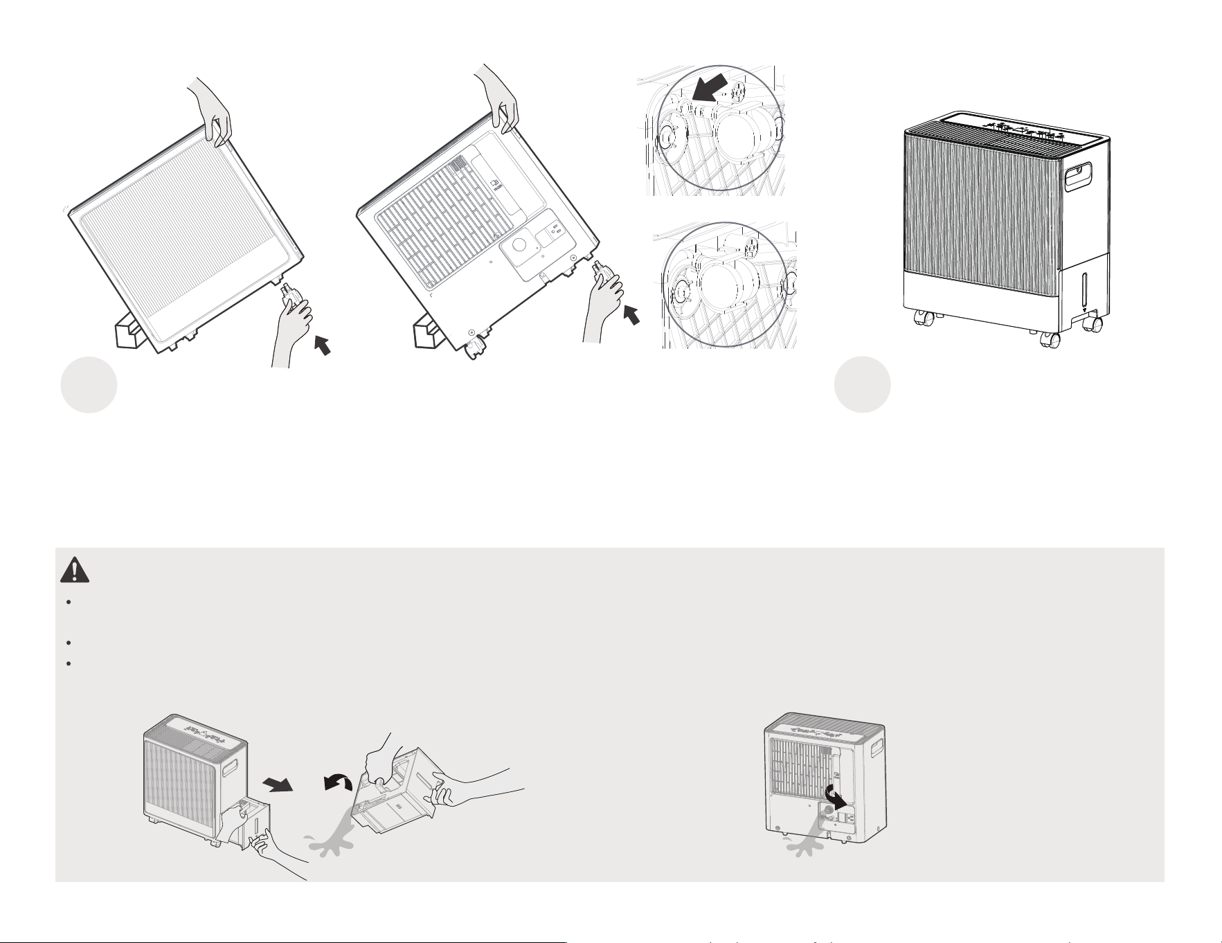
Caster installation
Caster (4 pc)
Pull out the water
bucket
Cushion pad(1 pc)
Remove the cover, take out a cushion pad and four
casters from the bucket, then reinstall the water
bucket
Caster
( 4 pc )
Accessories
Accessories
Optional accessories
pump drain hose( 1 pc* )
(For the unit with pump feature)
Cushion pad ( 1 pc )
Drain Hose ( 1 pc* )
NOTE
Items with (*) are on some models. Slight variations in design may occur.
NOTE:Make the
water pipe straight
when you use it
3 4
Step 2
WARNING:
Take out the bucket and removel water plug, drain the water outlet as shtep 1 and step 2, then reinstall the bucket
and water plug before installing casters.
The tilt Angle DO NOT be greater than 30° when installing casters, and all casters MUST BE installed within 5 minutes.
After the installation is complete, reset the unit and rest for 30 minutes before starting the unit.
Step 1
Leave the unit in a
vertical position for
half an hour before use
Step 1
Step 2
Tilt the unit on the
and hold it with one
hand,then insert two
casters
Rotate the unit and hold
it with one hand, then
insert the other two casters
Before inserting
Correct inserted
14
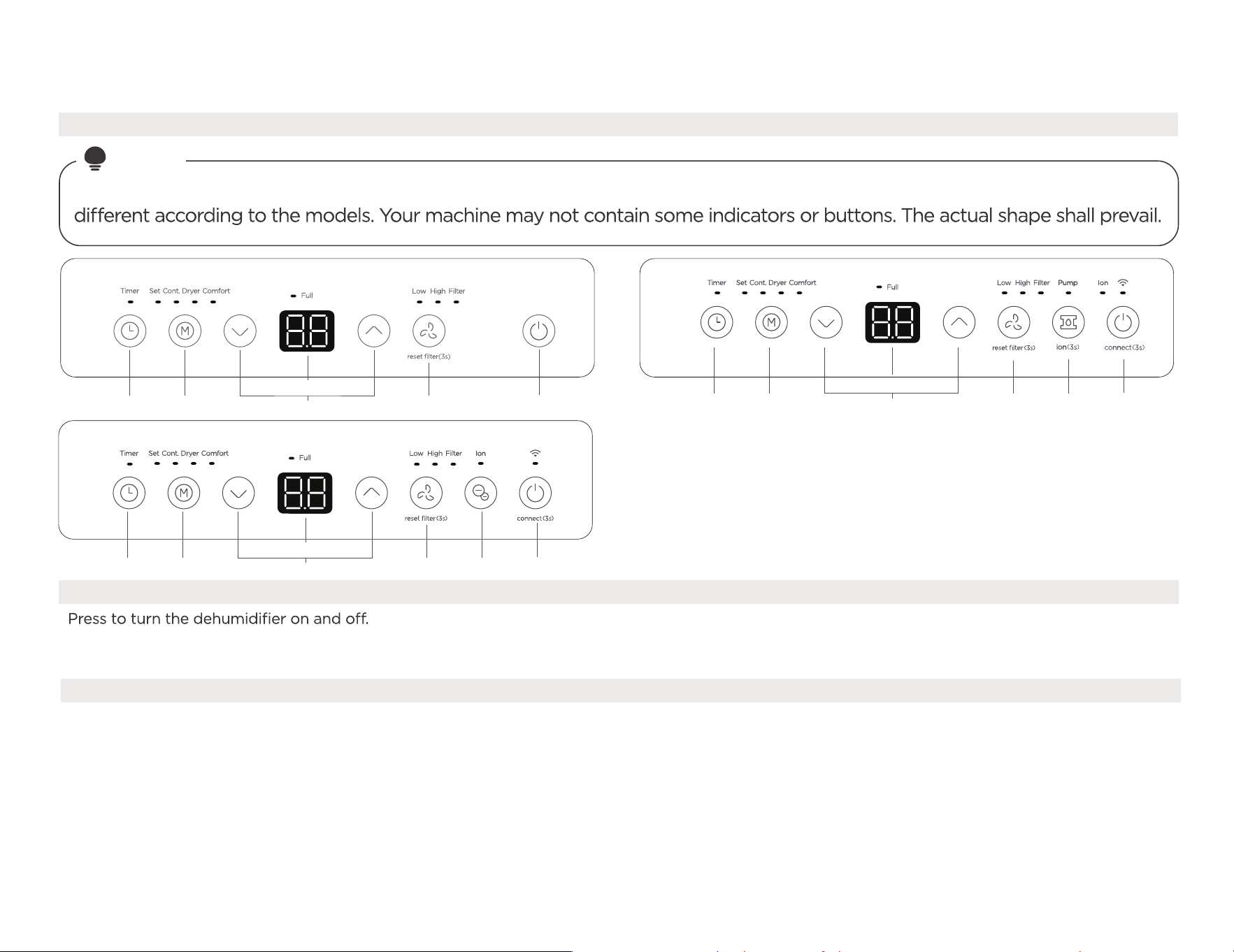
2.TIMER Function
Auto start setting
Press the button to initiate the Auto start and Auto stop function, in conjunction with the UP and DOWN buttons.
1. In the shutdown state, press the button to active the Auto start time.
2. Press or hold the UP or DOWN button to change the Auto start time by 0.5 hour increments, up to 10 hours,
then at 1 hour increments, up to 24 hours.
1.POWER ON/OFF button
Wireless button(On some models)
Get to know your features
Operation Display
NOTE
Control Panel Features
The following control panels are for explanation purpose only. The control panel of the unit you purchased may be slightly
15
2 3
6
4
15
7
8
2 3
6
4
4
8
15
2 3
6
15
-Pump
-ion
In this mode, the dehumidifier is always running
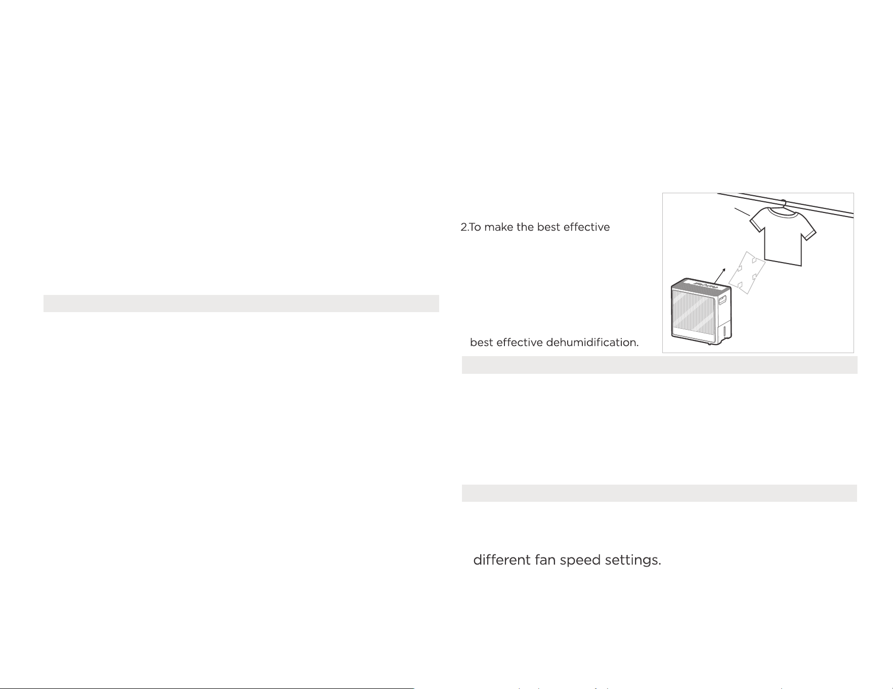
Dryer mode (Dryer)-optional
Press the button to select the Dryer mode, and the unit will operate in
Continuous dehumidifying and High fan speed mode, in this mode.
NOTE: For some models, The unit will quit Dryer mode
after a maximum 10 hours operation.
1. Close doors and Windows
while operating in this mode.
dehumidification, please
dehydrate the wet clothes
at first.
3.Make sure to direct airflow
at the wet clothes.
4.For thick and heavy wet
clothes may not get the
30~50cm
Wet clothes
30~50cm
Airflow
Allow 30~50cm of distance
on the top and right side of
the unit to the wet clothes.
4. UP and DOWN buttons
Humidity Set Control buttons
TIMER Set Control buttons
The humidity level can be set within a range of 35% RH(Relative
Humidity) to 85%RH(Relative Humidity) in 5% increments.
Press the UP and DOWN buttons to set the Auto start and Auto stop
time from 00:00 to 24:00.
5. FAN speed Function
Press the button to select fan speed in the following setting:
Low → High → Low...
NOTE: The fan speed indicator light illuminates under
16
3. The selected time will register in 5 seconds and the system will
automatically revert back to display the humidity.
The control will count down the time remaining until start.
Auto stop setting
1. In the startup state, press the button to active the Auto stop time.
2. Press or hold the UP or DOWN button to change the Auto stop time
by 0.5 hour increments, up to 10 hours, then at 1 hour increments, up
to 24 hours.
3. The selected time will register in 5 seconds and the system will
automatically revert back to display the humidity.
The control will count down the time remaining until stop.
NOTE: The timing can be adjusted to increase or decrease
by 24 hours.After the TIMER setting is complete, you can
press the button again to check the TIMER setting status.
After the TIMER setting is complete,you can cancel it by
setting the set time to 0.0.
3. MODE Function
NOTE: Humidity can be set from 35% to 85%, with 5%
adjustment perpress.In the Set dehumidification mode,
the compressor will stopwhen the set humidity is reached.
Continuous dehumidifying mode(Cont.)
Press the button to select the Continuous dehumidifying mode.
NOTE: Humidity cannot be adjusted in this mode.
Press the button to select the mode you want, as shown :
Set→ Cont. → Dryer →Comfort
NOTE: Dryer and Comfort are optional; The humidity setting
cannot be adjusted in Dryer, Cont. and Comfort; The set
humidity will be displayed when the mode is set to Set,
and the ambient humidity will be displayed 5 seconds later.
Set Dehumidifying mode(Set)
Press the button to select the Dehumidifying mode, and adjust the
desired humidity by pressing the UP and DOWN buttons.
Smart dehumidifying mode (Comfort)-optional
Press the button to select the Smart dehumidifying mode.
NOTE: Humidity cannot be adjusted in this mode. The unit
will automatically control room humidity in a comfortable
range 45%~55% according to the room temperature.
17
Display ambient humidity and setting humidity (humidity range: 30% to
90%); Display TIMER setting (timing range: 24 hours); Display error
codes reminder .
Error Codes:
6. Display
EH61 - Evaporator coil temperature sensor error. Unplug the unit
and plug it back in. If the error repeats, call for service.
EH60 - Room temperature sensor error. Unplug the unit and plug it
back in. If the error repeats, call for service.
P2 - Bucket is full of water or bucket is not in right position. Empty the
bucket and replace it in the right position.
Eb-For the water pump models, the unit will display "Eb" if the bucket
is not in the right position.
EH00 - Indoor EEPROM error. Unplug the unit and plug it back in. If
error repeats, call for service. (some units)
The system starts to count the time once the fan motor operates. The check filter feature can be only activated when the accumulated
operation time achieves 250 hours or more. The Reset light(Clean filter indicator light) flashes at one time per second, after finishing
clean the air filter, press the FAN(reset filter )
motor will continue to run for 30 seconds.
When the Full indicator light illuminates, please empty the bucket and reinstall it correctly. and the other problems are to install the bucket
correctly. Then, wait 3 minutes before resuming operation, it can not be restart operation in the first 3 minutes. This is to protect the unit.
Operation will automatically start after 3 minutes.
More Features
Check filter feature
Auto-Restart
.
When the tube temperature of the evaporator is lower than -1°C(30.2℉) and continues for a period of time, it will enter anti-freeze protection. The machine will
stop the compressor and run the fan at high speed. When the temperature is greater than 2°C(35.6℉), it will exit this mode.
Defrost function
.
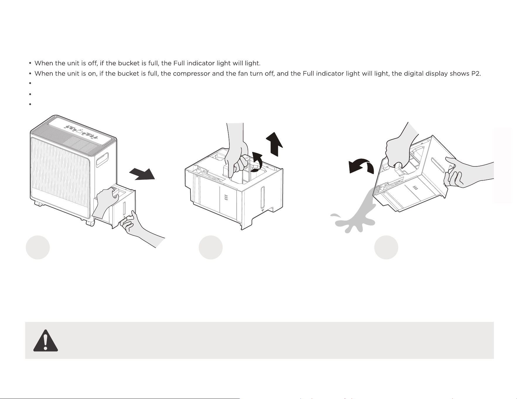
Dump the collected water
When your product has been
in use for a while.
There are three ways to remove collected water.
18
Bucket drainage
Type 1:
Type 2:
water hose drainage
(continuous)
19
Pull the bucket out halfway, then pull up the handle and lift the bucket slowly vertically to prevent spatter.
Throw away the water and replace the bucket. The bucket must be in right place and securely seated for the dehumidier to operate.
The appliance will re-start when the bucket is restored in its correct position.
Pull the bucket out
halfway.
Pull up the handle and
lift the bucket slowly
vertically.
Type 1
1
2
Pour the water out.
3
Bucket drainage
WARNING:
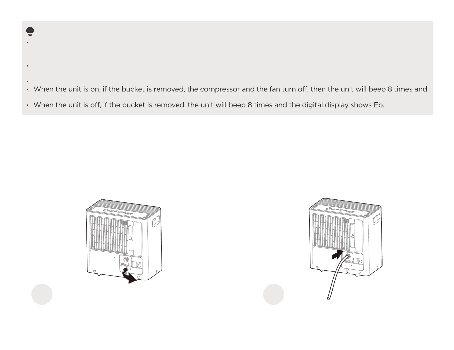
Do not pull out the whole bucket, or it may cause damage to the bucket or even injure you.
Water can be automatically emptied into a floor drain by attaching the unit with a water hose(ld ≥Φ5/16", not included) with a female threaded
end(ID:M=1",not included)
Note: On some models, the female threaded end is include.
Remove the water plug from the back drain outlet of the unit and set aside, then insert the drain hose through the drain outlet of the unit and
lead the drain hose to the floor drain or a suitable drainage facility.
When you remove the bucket, do not touch any parts inside of the unit. Doing so may damage the product.
Be sure to push the bucket gently all the way into the unit. Banging the bucket against anything or failing to push it in
securely may cause the unit not to operate.
If the pump hose drops when you remove the bucket, you must reinstall the pump hose properly to the unit before
replace the bucket into the unit.
When you remove the bucket,if there is some water in the unit you must dry it.
the digital display shows Eb.
NOTE
Type 2
water hose drainage (continuous)
Remove the water plug. Connect the drain hose.
1
2
20
When you remove the plastic cover, if there is some water in the back drain outlet of the unit you must dry it. Make sure the hose is
secure so there are no l eaks and the end of the hose is level or down to let the water flow smoothely.
Direct the hose toward the drain, making sure that there are no kinks that will stop the water flowing. Make sure the water hose is
lower than the drain hose outlet of the unit.
Select the desired humidity setting and fan speed on the unit for continuous draining to start.
NOTE : When the continuous draining feature is not being used, remove the drain hose from the outlet, and dry the
water in the continuous drain hose outlet.
21
Pump drainage (Pump model only)
NOTE
The maximum distance and the rise may be 5m from the unit. Exceeding this distance may damage the unit or
cause leaks.
If removing the hose to use in Bucket mode, please reinsert the drain plug to prevent accidental water leakage.
(You still need to press the tightening ring when removing the hose.)
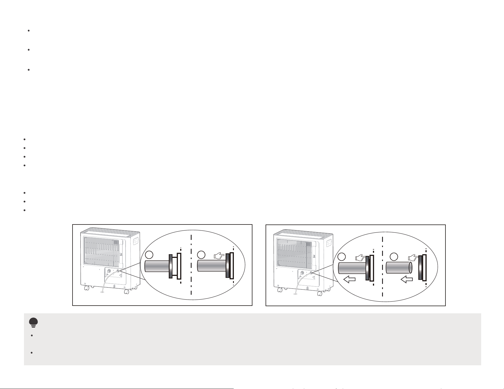
To connect pump drain hose:
Press the tightening ring of drainage joint(as shown as fig.1 );
Keep pressing the grey ring while pulling out the plug. (as shown as fig.2 );
Insert the drain hose onto the drainage joint, make sure it is connected well so that it is fully seated.
Place the other end of the drain hose in the location you want the water to go to a floor drain, a water container, or through a
To remove pump drain hose:
Press the tightening ring of drainage joint.
Place the plug back to the joint.
1 2
fig.1
3 4
fig.2
basement window to the outdoors.
To connect pump drain hose:
Press the tightening ring of drainage joint (
Keep pressing the grey ring while pulling out the plug.
Insert the drain hose onto the drainage joint, make sure it is connected well so that it is fully seated.
Place the other end of the drain hose in the location you want the water to go to a floor drain, a water container, or through
a
-Servicing shall only be performed as recommended by the
equipment manufacturer. Maintenance and repair requiring the
assistance of other skilled personnel shall be carried out under the
supervision of the person competent in the use of flammable
refrigerants.
-DO NOT modify the length of the power cord or use an extension
cord to power the unit.
-DO NOT share a single outlet with other electrical appliances.
Improper power supply can cause fire or electrical shock.
-Please follow the instruction carefully to handle, install, clear,
service the appliance to avoid any damage or hazard.
Flammable
Refrigerant R32 is used within appliance.
-When maintaining or disposing the appliance, the refrigerant
(R32) shall be recovered properly, shall not discharge to air directly.
-Compliance with national gas regulations shall be observed.
-Keep ventilation openings clear of obstruction.
-The appliance shall be stored so as to prevent mechanical damage
from occurring.
-A warning that the appliance shall be stored in a well-ventilated
area where the room size corresponds to the room area as
specified for operation.
-Any person who is involved with working on or breaking into a
refrigerant circuit should hold a current valid certificate from an
industry-accredited assessment authority, which authorises their
competence to handle refrigerants safely in accordance with an
industry recognised assessment specification.
Examples for such working procedures are:
• breaking into the refrigerating circuit;
• opening of sealed components;
• opening of ventilated enclosures.
-No any open fire or device like switch which may generate
spark/arcing shall be around appliance to avoid causing
ignition of the flammable refrigerant used. Please follow the
instructions carefully when storing or maintaining the appliance to
prevent mechanical damage from occurring.
Type 3
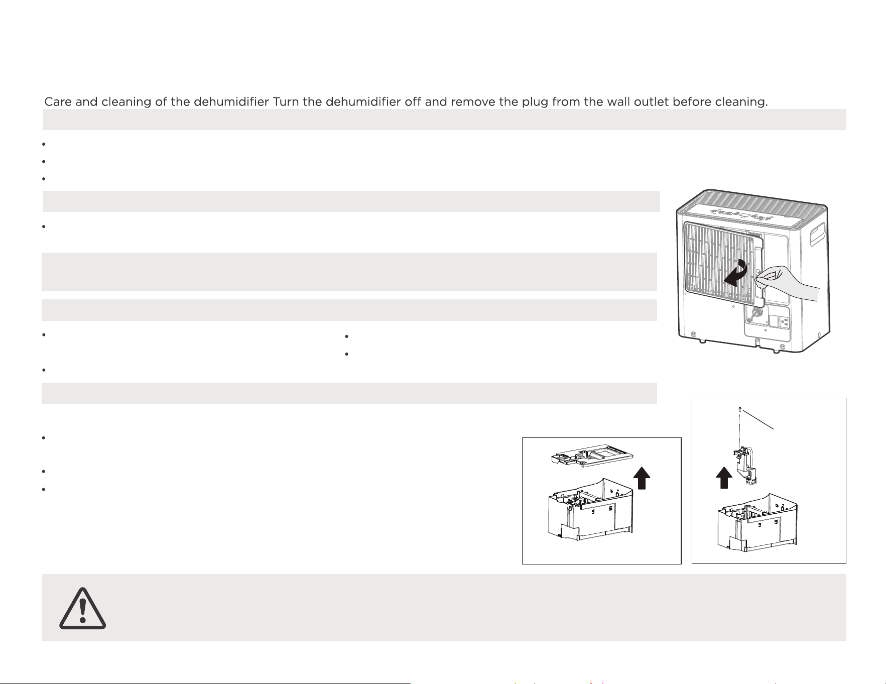
Clean the Grille and Case
Care and Maintenance
Use water and a mild detergent. Do not use bleach or abrasives.
Do not splash water directly onto the main unit. Doing so may cause an electrical shock, cause the insulation to deteriorate, or cause the unit to rust.
The air intake and outlet grilles get soiled easily, so use a vacuum attachment or brush to clean.
Every few weeks, clean the bucket to prevent growth of mold, mildew and bacteria.
Partially fill the bucket with clean water and add a little mild detergent. Swish it around in the bucket, empty and rinse.
Note: Do not use a dishwasher to clean the bucket. After clean, the bucket must be in
place and securely seated for the dehumidifier to operate.
CAUTION
DO NOT operate the dehumidifier without a filter because dirt and lint will clog it and reduce performance.
Clean the bucket
Remove the filter every two weeks based
on normal operating conditions.
To remove the filter, pull filter outwards.
Wash the filter with clean water then dry.
Re-install the filter, replace Bucket.
Clean the air filter
How to clean & maintenance your product.
22
Place the other end of the drain hose in the location you want the water to go to a floor drain, a water container, or through a
Clean the pump filter every two weeks based on normal operating conditions.
Take out the water bucket from the unit and remove the bucket top cover. (as
shown as fig.3 )
Remove the screw as shown as fig.4 .
Take out the pump drainage structure and clean the filter at the button
of the hose.
Reinstall the filter and pump drainage structure to the water bucket.
Clean the pump filter
Remove
the screw
Fig. 4
Fig. 3
1)Checks to the area
Prior to beginning work on systems containing flammable
refrigerants, safety checks are necessary to ensure that the risk of
ignition is minimised. For repair to the refrigerating system, the
following precautions shall be complied with prior to conducting
work on the system.
2)Work procedure
Work shall be undertaken under a controlled procedure so as to
minimise the risk of a flammable gas or vapour being present while
the work is being performed.
3)General work area
All maintenance sta� and others working in the local area shall be
instructed on the nature of work being carried out. Work in
confined spaces shall be avoided. The area around the workspace
shall be sectioned o�. Ensure that the conditions within the area
have been made safe by control of flammable material.
4)Checking for presence of refrigerant
The area shall be checked with an appropriate refrigerating
detector prior to and during work, to ensure the technician is aware
of potentially flammable atmospheres. Ensure that the leak
detection equipment being used is suitable for use with flammable
refrigerants, i.e. non-sparking, adequately sealed or intrinsically safe.
5)Presence of fire extinguisher
If any hot work is to be conducted on the refrigeration equipment
or any associated parts, appropriate fire extinguishing equipment
shall be available to hand. Have a dry powder or CO2 fire
extinguisher adjacent to the charging area.
6)No ignition sources
No person carrying out work in relation to a refrigerating system
which involves exposing any pipe work that contains or has
contained flammable refrigerant shall use any sources of ignition in
such a manner that it may lead to the risk of fire or explosion. All
possible ignition sources, including cigarette smoking, should be
kept su�ciently far away from the site of installation, repairing,
removing and disposal, during which flammable refrigerant can
possibly be released to the surrounding space. Prior to work taking
place, the area around the equipment is to be surveyed to make
sure that there are no flammable hazards or ignition risks. No
Smoking signs shall be displayed.
-Servicing shall only be performed as recommended by the
equipment manufacturer. Maintenance and repair requiring the
assistance of other skilled personnel shall be carried out under the
supervision of the person competent in the use of flammable
refrigerants.
-DO NOT modify the length of the power cord or use an extension
cord to power the unit.
-DO NOT share a single outlet with other electrical appliances.
Improper power supply can cause fire or electrical shock.
-Please follow the instruction carefully to handle, install, clear,
service the appliance to avoid any damage or hazard.
Flammable
Refrigerant R32 is used within appliance.
-When maintaining or disposing the appliance, the refrigerant
(R32) shall be recovered properly, shall not discharge to air directly.
-Compliance with national gas regulations shall be observed.
-Keep ventilation openings clear of obstruction.
-The appliance shall be stored so as to prevent mechanical damage
from occurring.
-A warning that the appliance shall be stored in a well-ventilated
area where the room size corresponds to the room area as
specified for operation.
-Any person who is involved with working on or breaking into a
refrigerant circuit should hold a current valid certificate from an
industry-accredited assessment authority, which authorises their
competence to handle refrigerants safely in accordance with an
industry recognised assessment specification.
Examples for such working procedures are:
• breaking into the refrigerating circuit;
• opening of sealed components;
• opening of ventilated enclosures.
-No any open fire or device like switch which may generate
spark/arcing shall be around appliance to avoid causing
ignition of the flammable refrigerant used. Please follow the
instructions carefully when storing or maintaining the appliance to
prevent mechanical damage from occurring.
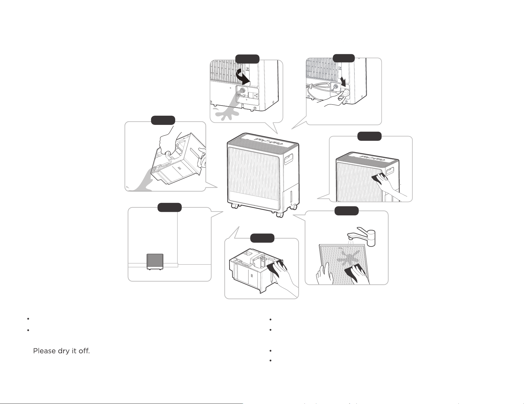
Wrap the cord with the power cord buckle.
Place the unit in straight up and replace the bucket properly,
make sure the bucket is flush with the front panel of the unit.
Cover the unit with a plastic bag.
Store the unit upright in a dry, well-ventilated place.
Clean the main unit, water bucket and air filter.
When not using the unit for long time periods
Step 4
Step5
Step 1
Step 6
Step7
23
It is normal that the water tray will have a small amount
of water droplets to the chassis after take out the bucket.
Step 2
*Please refer to the
actual plug, and the legend
is for reference only.
Step 3
1)Checks to the area
Prior to beginning work on systems containing flammable
refrigerants, safety checks are necessary to ensure that the risk of
ignition is minimised. For repair to the refrigerating system, the
following precautions shall be complied with prior to conducting
work on the system.
2)Work procedure
Work shall be undertaken under a controlled procedure so as to
minimise the risk of a flammable gas or vapour being present while
the work is being performed.
3)General work area
All maintenance sta� and others working in the local area shall be
instructed on the nature of work being carried out. Work in
confined spaces shall be avoided. The area around the workspace
shall be sectioned o�. Ensure that the conditions within the area
have been made safe by control of flammable material.
4)Checking for presence of refrigerant
The area shall be checked with an appropriate refrigerating
detector prior to and during work, to ensure the technician is aware
of potentially flammable atmospheres. Ensure that the leak
detection equipment being used is suitable for use with flammable
refrigerants, i.e. non-sparking, adequately sealed or intrinsically safe.
5)Presence of fire extinguisher
If any hot work is to be conducted on the refrigeration equipment
or any associated parts, appropriate fire extinguishing equipment
shall be available to hand. Have a dry powder or CO2 fire
extinguisher adjacent to the charging area.
6)No ignition sources
No person carrying out work in relation to a refrigerating system
which involves exposing any pipe work that contains or has
contained flammable refrigerant shall use any sources of ignition in
such a manner that it may lead to the risk of fire or explosion. All
possible ignition sources, including cigarette smoking, should be
kept su�ciently far away from the site of installation, repairing,
removing and disposal, during which flammable refrigerant can
possibly be released to the surrounding space. Prior to work taking
place, the area around the equipment is to be surveyed to make
sure that there are no flammable hazards or ignition risks. No
Smoking signs shall be displayed.
Technical Parameters
24
SKU:
Power Supply
Moisture removal
Refrigerant
Gross Weight
Net Weight
Dimension
ZX-DH-22-AZ-HM
22.00pint/day
R32/3.53oz
33.07lb
30.86lb
15.94x8.86x16.97in
ZX-DH-35-AZ-HM
115V~60Hz
35.37pint/day
R32/4.94oz
36.60lb
33.73lb
18.50x8.86x15.94in
ZX-DH-50-AZ-HM
49.95pint/day
R32/5.64oz
44.75lb
41.45lb
18.82x9.92x20.04in
Problem What to check
Before calling for service, review the chart below first yourself.
Unit does not start
Make sure the dehumidifier s plug is pushed completely into the outlet.
Check the house fuse/circuit breaker box.
Dehumidifier has reached its preset level or bucket is full.
Water bucket is not in the proper position.
The air filter is clogged.
The unit is tilted instead of upright as it should be.
The floor surface is not level.
Hose to connector or hose connection may be loose.
Intend to use the bucket to collect water, but the back drain plug is removed.
This is normal. The dehumidifier has Auto defrost feature.
These are error codes and protection codes. See the CONTROL PANEL FEATURES section.
Do not allow enough time to remove the moisture.
Make sure there are no curtains, blinds or furniture blocking the front or back of the dehumidifier.
The humidity control may not be set low enough.
Check that all doors, windows and other openings are securely closed.
Room temperature is too low , below 5°C(41°F).
Dehumidifier does not
dry the air as it should
The unit makes a loud
noise when operating
Frost appears on the coils
Water on floor
EH61, EH60,P2,Eb appear in
the display
Troubleshooting
25
The design and specifications are subject to change without prior notice for product improvement. Consult with the sales agency or manufacturer
for details. Any updates to the manual will be uploaded to the service website, please check for the latest version.

Warranty And Service
26
This product is covered by a 12-month product and warranty from the date of initial purchase in case of any problems,
please contact the Customer Service Center via the contact information listed in this User Guide.
Our warranty covers replacement products by repairing or replacing any defective parts and labor necessary to bring it up to
its original specifications, and we can provide a replacement product instead of repairing the defective product. Our sole
obligation under this warranty is limited to such repair or replacement.
Any claim will require a receipt showing the date of purchase, so please keep all receipts in a safe place. While greatly
appreciated, product registrant is not required to activate any warranty and product registration does not eliminate the need
for proof of original purchase. The warranty will be voided if repairs are performed by a non-authorized third party and/or if
spare parts other than those provided by us are used, These are the general terms of our warranty service, but we always
urge our customers to contact us ([email protected]) with any questions they may have, regardless of the terms of the
warranty.


CD001UI-DA
16120100A20695