
Service Manual
IMPORTANT: READ SAFETY RULES AND INSTRUCTIONS CAREFULLY
PRINTED IN USA
FORM NO.769-00965
This Service Manual is not a substitute for the Operator’s Manual. You must read, understand
and follow all of the directions in this manual as well as the Operator’s Manual before working
on this power equipment.
(11/2003)
CUB CADET LLC, P.O. BOX 361131, CLEVELAND, OH 44136-0019
Cub Cadet Big Country 4x2


TABLE OF CONTENTS
Brakes............................................................................................................... 1
Visual Inspection............................................................................................... 1
Operational Tests.............................................................................................. 2
Complete Inspection.......................................................................................... 3
Brake Adjustment.............................................................................................. 7
Brake Linkage Adjustment ................................................................................ 9
4x2 Drive – Dana Transaxle.............................................................................. 13
Engine/Transmission Cradle ............................................................................. 13
“Dogbone” Link Assembly ................................................................................. 13
Transaxle Maintenance..................................................................................... 13
Transaxle Removal ........................................................................................... 14
4x2 Pushbutton Gear Selector .......................................................................... 15
Description ........................................................................................................ 15
Self Diagnostics................................................................................................. 18
Terms and Definitions ....................................................................................... 19
Gear Selector System Diagnostics.................................................................... 20
Explanation of Methodology.............................................................................. 20
Basic Checks .................................................................................................... 20
Vacuum Tests ................................................................................................... 23
Differential Lock Actuator .................................................................................. 27
Gear Selector Electrical System........................................................................ 28
Differential Lock................................................................................................. 31

1
IMPORTANCE:
It is important that the brakes of the Big Country 4 X 2
Utility Vehicle be properly maintained in order for the
utility vehicle to operate safely and dependably. In
addition to the obvious safety concerns, there is an
electric interlock between the brakes and the gear
selector mechanism. If the brakes are out of adjust-
ment, the gear selector mechanism will not work as it
was designed to. The condition and adjustment of the
brake system should be checked in accordance with
the two-tiered service interval described under the
“Service Intervals” heading in “Description of the Brake
System”.
DESCRIPTION OF THE BRAKE SYSTEM:
• The brake pedal arm lifts up on the pull bolt that
transfers the force through a stack of bellville
washers to an equalizer bracket. The equalizer
bracket distributes the brake pedal force
between the cores of two cables. The bellville
washers are stacked in opposite directions to
provide a spring action, softening the brake
pedal feel.
• Each cable housing is mounted to a bracket on
the firewall using two large jam nuts. Each cable
actuates a drum brake at the end of each rear
axle.
•A parking brake latches the brake pedal in the
applied position when engaged.
• There are two electrical switches in the sys-
tem. A parking brake switch lights an indicator
bulb in the instrument panel to help prevent the
operator from trying to drive the Big Country 4 X
2 with the brakes engaged. A brake switch
works with the Electronic Shift Module to prevent
the operator from shifting gears without the
brake applied.
• Service intervals will vary with the type severity
of use. If the vehicle is operated on hills or with
heavy loads, it may be necessary to shorten the
maintenance intervals because of the increased
load on the brake system and the increased con-
sequences of brake system failure. A visual
inspection and operational test should be per-
formed every 50 hours. The brake drums
should be removed for a complete inspection
every 500 hours or 24 months, as the tran-
saxle gear lube is being changed.
1. VISUAL INSPECTION AND
OPERATIONAL TEST:
1.1. Open the hood of the Big country 4 X 2 and
examine the brake arm, parking brake latch, and
all of the associated hardware.
1.2. Check the condition of the brake cables and
their mounting hardware: See Figure 1.2.
• Jam nuts at the front should be secure.
• Locating clamps at the front of the engine com-
partment should be secure.
• Mounting clips and clevis pins at the back end of
the cable housing should be secure and in good
condition.
• Cable cores should not be frayed or corroded.
Rubber boots should be intact.
• Cable housings should not be kinked, chafed,
burned, crushed or otherwise damaged.
1.3. Any significant wear, damage, or binding should
be addressed prior to making an operational
test.
Figure 1.2
Left brake
Cable
Fuel tank
clamp
cable
Big Country 4 x 2
Big Country 4 x 2
2
1.4. If the operator of the vehicle has any specific
brake performance complaints, these complaints
should direct the visual examination and be con-
firmed during the operational test. If the opera-
tor describes an inherently unsafe condition, a
complete inspection should be performed in lieu
of the operational test.
2. OPERATIONAL TESTS
2.1. Operational be performed in a safe location that
is free of traffic, obstacles and hazards.
See Figure 2.1.
2.2. Check the following points of performance:
2.3. The brakes should not drag when they are not
applied.
2.4. The gear selector buttons should operate when
there is enough pressure on the brake pedal to
prevent vehicle motion.
2.5. When the brakes are applied at speed, there
should be no unusual noises, and no pedal pul-
sation.
2.6. When the brakes are applied at speed on a low-
coefficient surface (such as a gravel parking lot)
the brakes should lock both rear wheels at the
same time.
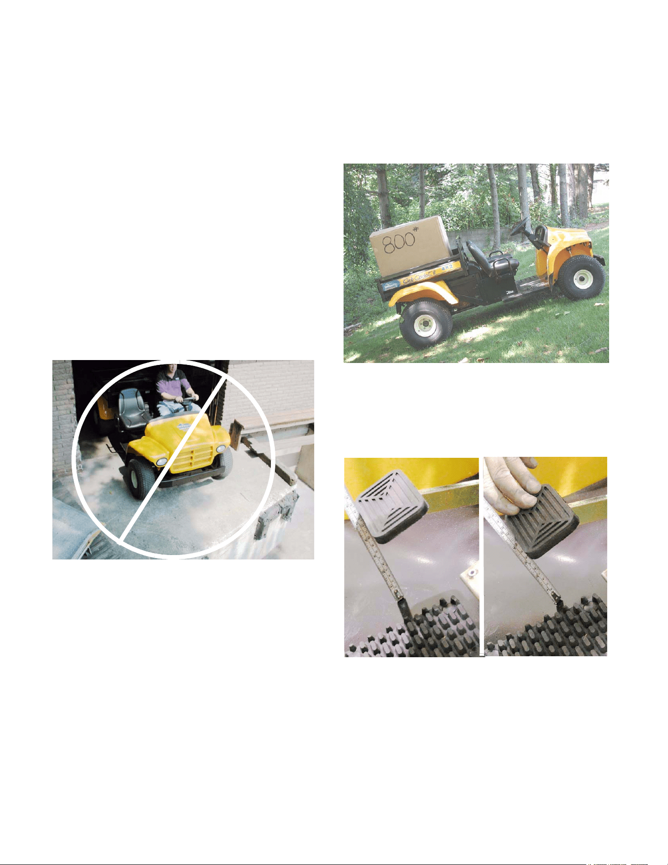
2.7. The parking brake should hold the vehicle
securely on a 22 degree incline with an operator
and a capacity load (800lbs.) in the bed. It
should take less than 100 pounds of pedal pres-
sure to push the pedal down far enough to
engage the parking brake. See Figure 2.7.
2.8. There should be 7/8” of pedal travel as mea-
sured at the edge of the brake pedal pad before
pressure on the pedal begins to build.
See Figure 2.8.
2.9. If the Big Country 4 X 2 does not perform as
described, adjust the brakes as described in the
“Brake Adjustment” section of this manual.
2.10. If adjustment does not completely fix the prob-
lem, follow the procedures described in the
“Complete Inspection” section of this manual,
and repair any mechanical faults encountered.
Figure 2.1
Figure 2.7
.875” free-play
from here...........to here
Figure 2.8
Big Country 4 x 2
3
3. COMPLETE INSPECTION
(DRUM AND SHOE REMOVAL)
3.1. Perform operational tests if no unsafe conditions
have been described by the operator.
NOTE: All brake repair work should be done in
compliance with applicable OHSHA and EPA
regulations.
3.2. Loosen the five lug nuts on each rear wheel 1/2
turn each using a 3/4” socket.
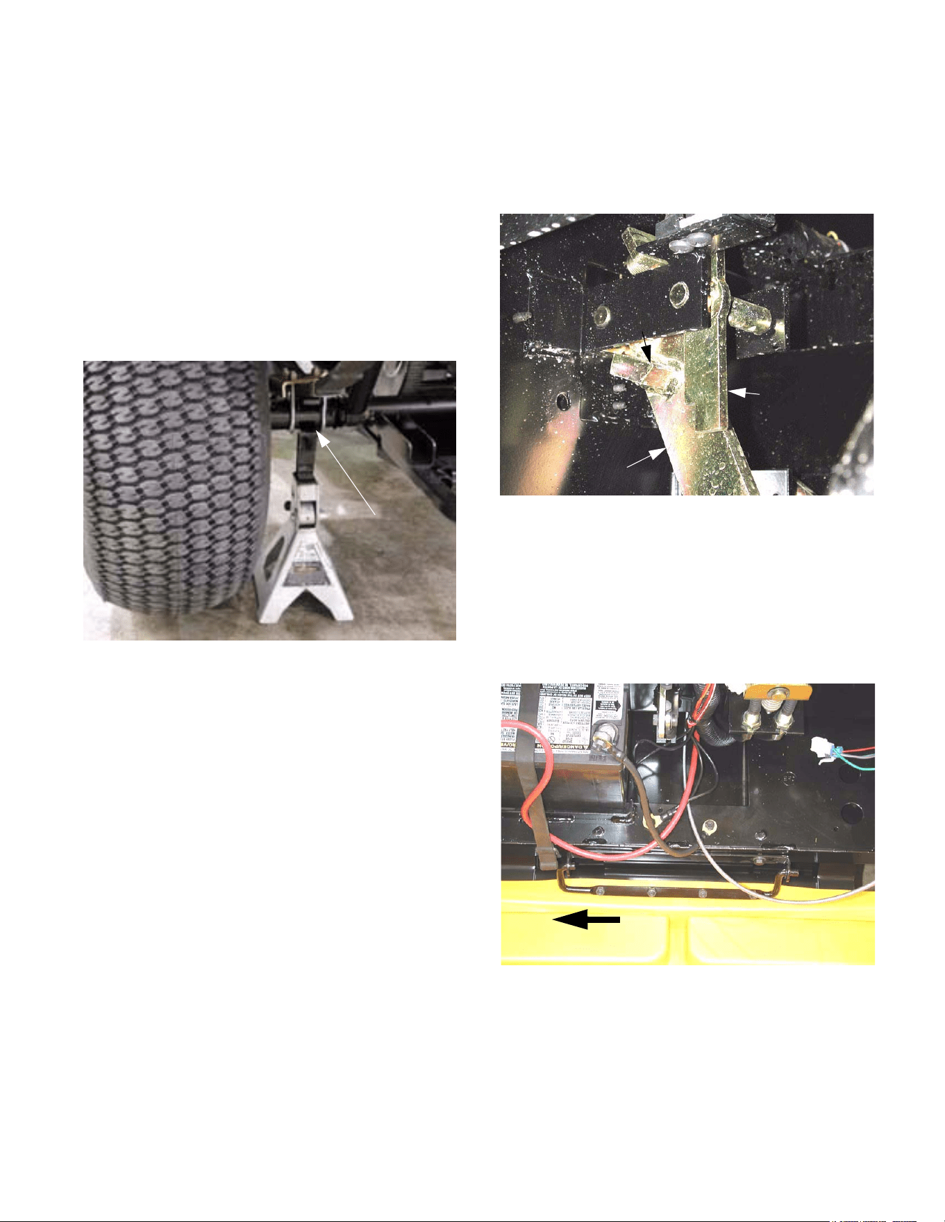
3.3. Raise and safely support the rear of the Big
Country 4 X 2 with jack stands. See Figure 3.3.
3.4. With the parking brake disengaged, attempt to
rotate the rear wheels. They should not drag. If
one or both rear wheels are difficult to rotate,
check the adjustment as described in the “Brake
Adjustment “ section of this manual.
Figure 3.3
location
Safe jack
3.5. Engage the parking brake. Insure the parking
brake assembly is engaging and disengaging
properly. The latch (parking brake lever) should
hook securely over the tab on the brake pedal
arm. See Figure 3.5.
3.6. Attempt to rotate the rear wheels (drive wheels)
by hand. Neither wheel should rotate.
3.7. If either wheel rotates: release the parking brake
and check the adjustment as described in the
“Brake Adjustment “ section of this manual.
3.8. Open or remove the hood. See Figure 3.8.
NOTE: With some front mounted accessories in
place, it may be easier to open the hood far
enough to remove the hairpin clip from the hood
mounting pin, slide the hood assembly to the
right, and remove it completely
Figure 3.5
pedal arm
Parking
brake lever
Tab
Brake
Figure 3.8
Slide to remove
Big Country 4 x 2
4
3.9. Inspect the brake cables for any damage or
wear. Inspect the hardware securing the cables
to the brake pedal assembly.
See Figure 3.9.
3.10. Release the parking brake.
3.11. Inspect the brake cables at the rear drive
wheels. Inspect the clevis pin, cotter pin, E-clip,
cotter pin, and washer securing the the brake
cables and the brake actuator hardware. See
3.11..
3.12. Remove the rear wheels.
3.13. Remove the brake drums. If the brake drum will
not slide easily over the brake shoes, perform
the following two steps.
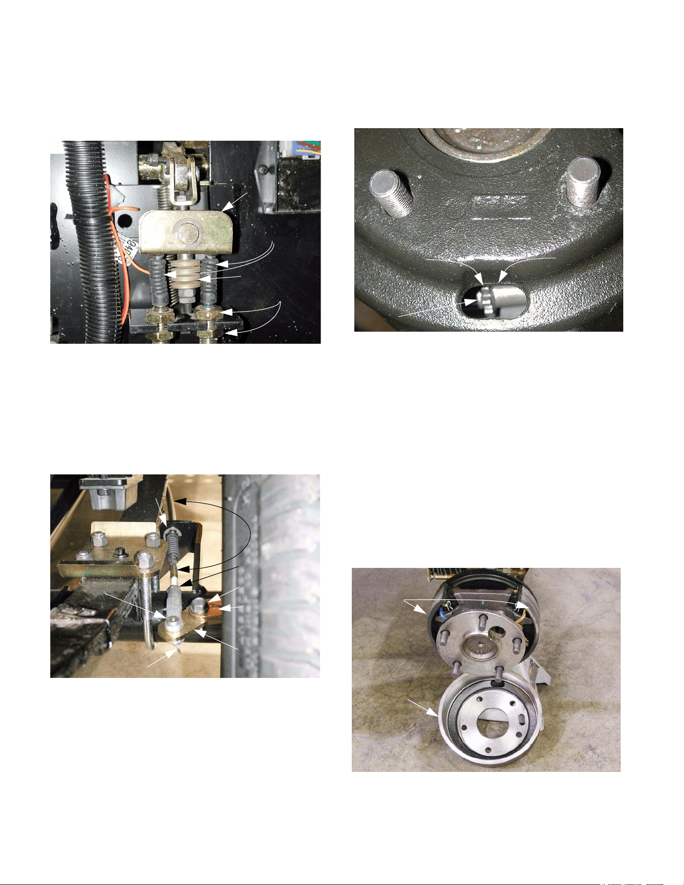
3.14. Rotate the brake drum until the access hole
(closest to the outer edge of the hub) is at the 6
O’clock position.
3.15. Slacken the brake adjuster using a brake
adjuster spoon or flat blade screw driver.
See Figure 3.15.
NOTE: The brake adjuster is the same on both
sides of the Big Country, but is installed in oppo-
site directions. The adjuster is installed with the
star wheel toward the front of the left side brake
assembly. The adjuster is installed with the star
wheel towards the rear of the right side brake
assembly. There is a conventional right hand
thread on the shaft attached to the star wheel.
Walk the teeth of either star wheel down in
order to loosen the brake shoe adjustment.
Walk the teeth up in order to tighten the
adjustment.
3.16. Inspect the brake shoes and drum for wear. The
shoes should be free of oil. See Figure 3.16.
Figure 3.9
Brake cables
Jam nuts
Bellville washer
s
Equalizer bar
Cable
E-clip
Jam nut
Brake actuator
Brake actuator
extension arm
Mounting bolts
Clevis pin
Cotter pin
Figure 3.11
Figure 3.15
brake drum
Window in
Brake
adjuster
Star
wheel
Figure 3.16
Brake
drum
Brake
shoes
Big Country 4 x 2
5
NOTE: If the friction material is contaminated
with oil, identify the source, repair the leak, and
replace the shoes.
NOTE: The friction material on the brake
shoes should not be worn to a thickness of less
than 3/32”. The friction material should not be
contaminated with oil. The friction material
should not show any signs of separating from
the steel portion of the brake shoe. If any of
these conditions exist, replace the brake shoes.
NOTE: If drums are reused at the time of reline,
they should be turned if the depth of scoring
exceeds .010"; if the inside diameter at the open
end of the drum exceeds the inside diameter at
the closed end by more than .010: (bellmouth
condition); if the drum rubbing surface is con-
cave or convex by more than .005"; if they are
heat checked; and if they are out of round by
more than .010 total indicator reading or if pedal
pulsations or brake roughness is noticed. The
rebore limit is .060" over the original maximum
drum diameter of 7.005". If reboring to .060”
maximum does not correct any of these condi-
tions, then the drum should be replaced. New
drums have a #50 grit blast applied to the rub-
bing surface. Drum surface finish is 40-125
micro-inches friction surface of the drum should
be smooth and true within .003 “.
3.17. Remove the cotter pins and clevis pins securing
the brake cables to the actuators on each brake.
The brake pedal may be carefully depressed
while the cable is disconnected from the actua-
tor. This will confirm that the cable and linkage
move without binding. See Figure 3.17.
Figure 3.17
Clevis
Brake Actuator
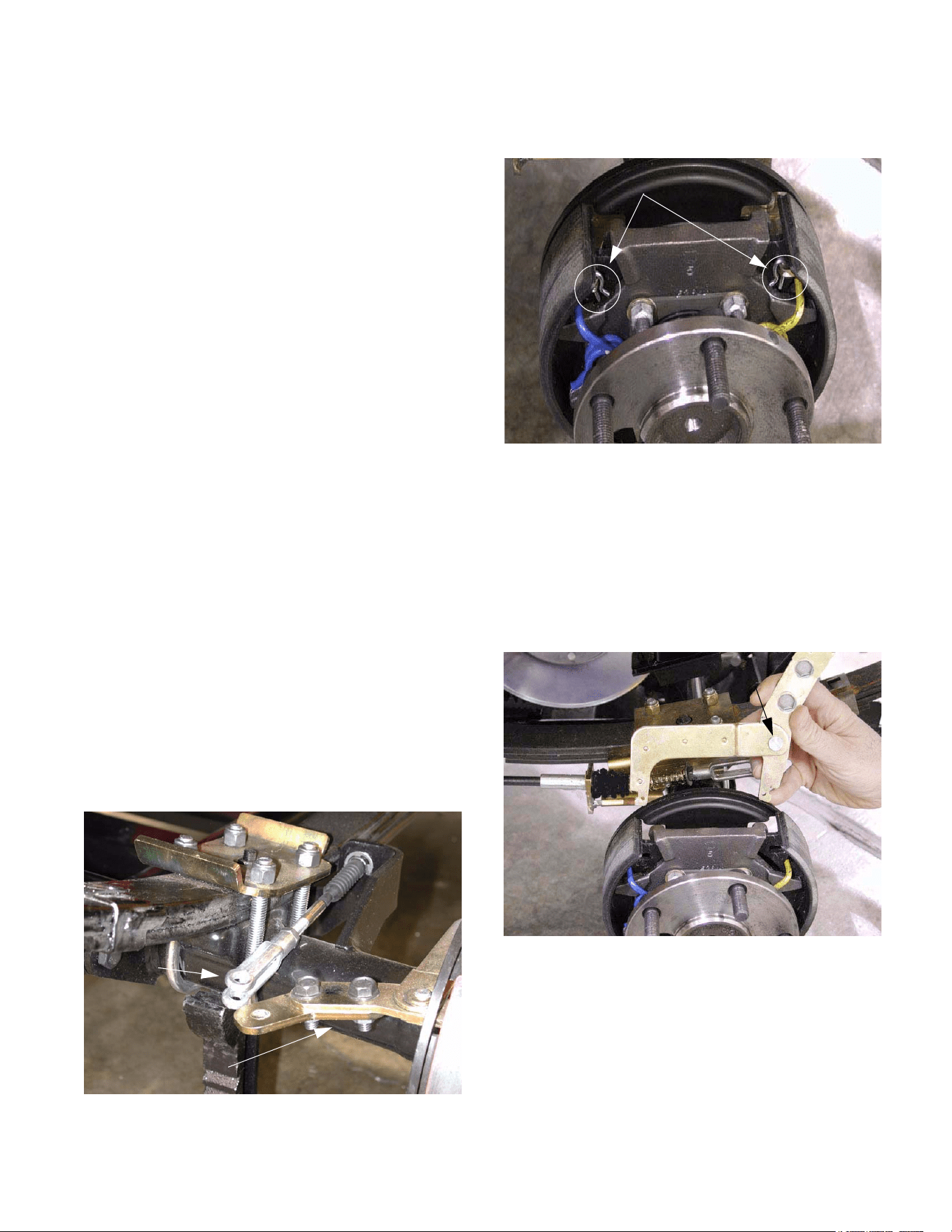
3.18. Remove the “R” shaped clips securing the brake
actuator to the brake shoes. See Figure 3.18.
3.19. Remove the brake actuator.
NOTE: The clevis pin is installed in the hole fur-
thest from the pivot pin. The head of the pivot is
facing. The Pivot pin is secured to the actuator
by a C-clip and wave washer.
3.20. Inspect the actuator for any binding at the pivot
pin. See Figure 3.20.
3.21. Rotate the star wheel on the adjuster to shorten
the adjuster to the end of its travel.
Figure 3.18
“R” Shaped clips
Figure 3.20
Check for binding
and wear
Big Country 4 x 2
6
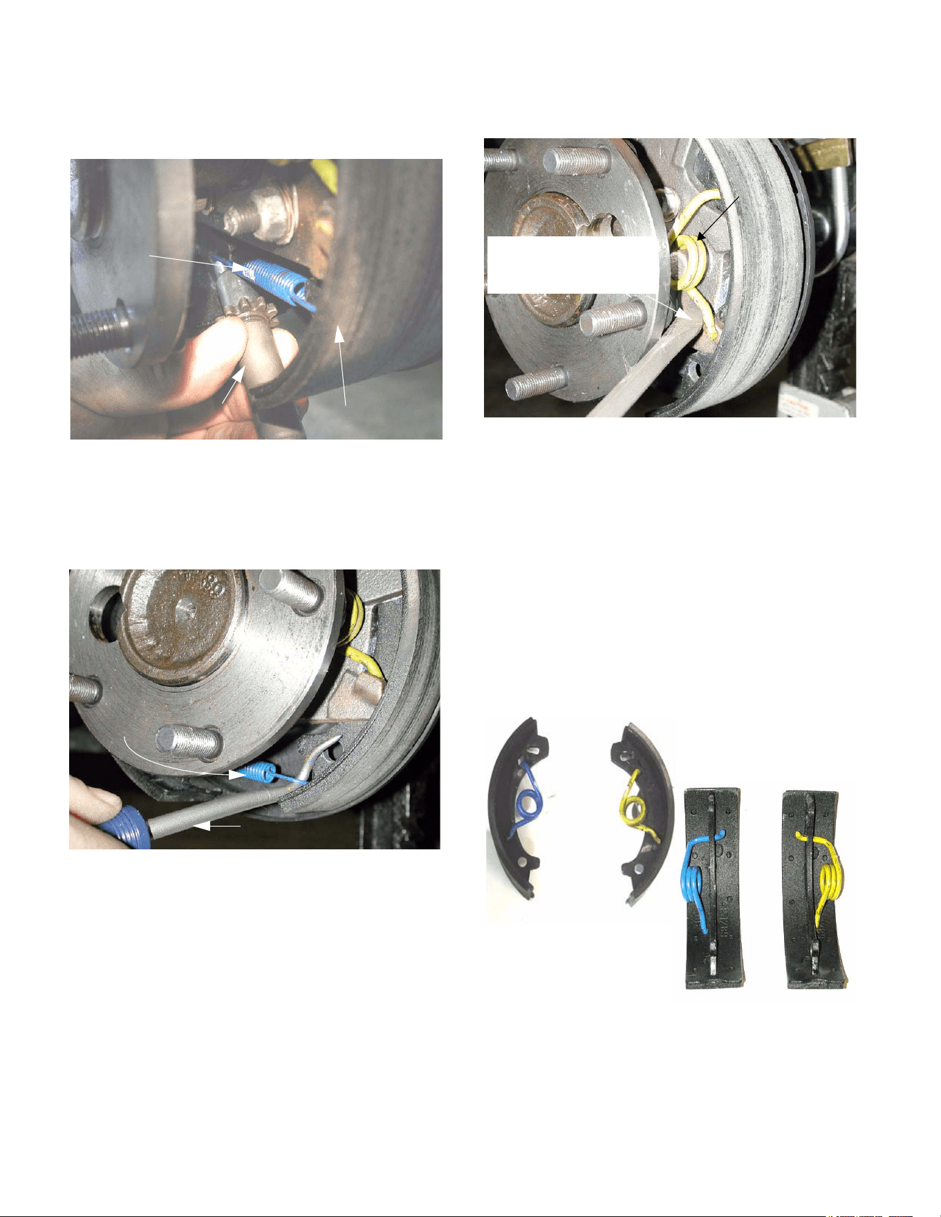
3.22. Pry out on the base of the brake shoes while
removing the adjuster. See Figure 3.22.
3.23. Remove the blue extension spring from the base
of each brake shoe. The extension spring keeps
the adjuster in contact with the base of the brake
shoe. See Figure 3.23.
3.24. Remove the torsion springs. See Figure 3.24.
NOTE: Relieve the tension from the torsion
spring by prying up on the bottom of the spring
until it separates from the ledge on the brake
shoe.
NOTE: There is one blue and one yellow torsion
spring on each brake assembly. The blue
spring is installed towards the front on the
right side brake assembly and towards the
rear on the left side brake assembly.
3.25. Slide the brake shoes out from behind the cast
ears that hold them in place, and remove them.
See Figure 3.25.
3.26. Replace any damaged, worn, or corroded parts.
Figure 3.22
Brake adjuster
Brake Shoe
extension
Blue
spring
Figure 3.23
Cotter pin tool
Blue
extension
spring
Figure 3.24
Spring
Torsion
Release from bottom lip
using a screwdriver
or brake spoon
Figure 3.25
Brake Shoe and
Spring Orientation
Big Country 4 x 2
7
3.27. Assemble the brakes by reversing the shoe
removal process. See Figure 3.27.
NOTE: Apply a small amount of white lithium
grease to the metal-to-metal contact points as
the brake is assembled.
NOTE: Measure the bore of each drum, then set
the adjuster to bring the brake shoes for that
drum out to slightly less than the I.D. of the
drum. If a brake shoe and drum caliper is not
available, a tape measure will usually provide a
measurement that is close enough.
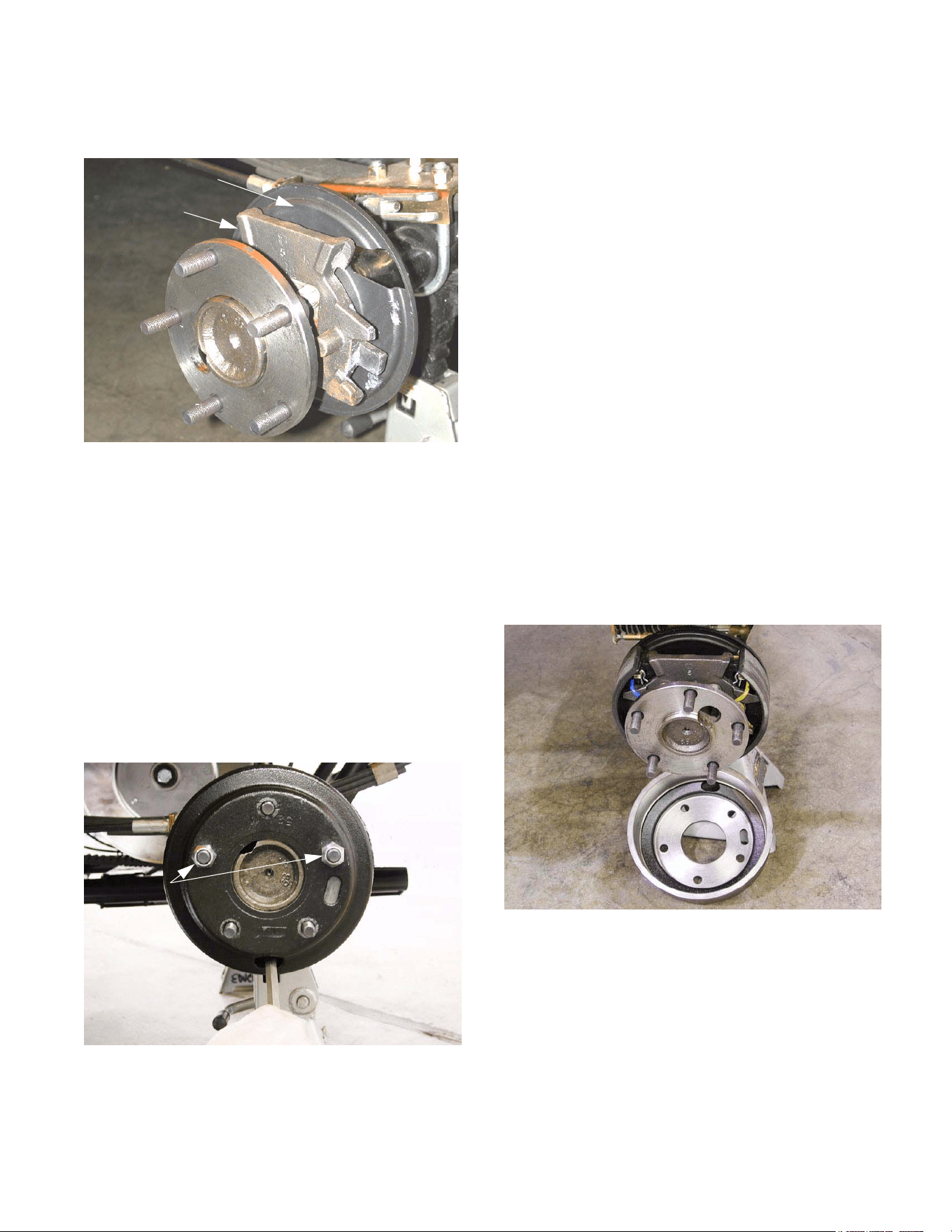
3.28. Install the brake drum without the wheel using
two of the five lug nuts. Install the lug nuts
inside-out, so that the flat side is against the
brake drum. See Figure 3.28.
NOTE: Rotate the brake drum as the lug nuts
are tightened to insure that it is centered.
Brake
mounting plate
Dust cover
Figure 3.27
Figure 3.28
Lug nuts
3.29. Adjust the brakes as described in the “Brake
Adjustment” section of this manual.
3.30. After brake adjustment is complete, perform the
operational test as described in the “Visual
Inspection and Operational Test” section of this
manual.
4. BRAKE ADJUSTMENT
4.1. If the brake adjustment is being performed after
other brake service, such as brake shoe
replacement or brake cable replacement, begin
with the “Brake Shoe Adjustment” step. Con-
tinue with the “Brake Linkage Adjustment”.
4.2. If brake adjustment is being performed as part of
scheduled maintenance or because of a per-
formance complaint, begin by performing the
steps of the “Complete Inspection” section of this
manual up through the point of brake drum
removal, then proceed from the “Brake Shoe
Adjustment” step. Continue with “Brake Linkage
Adjustment”.
BRAKE SHOE ADJUSTMENT:
4.3. With the brake drums removed, make a visual
inspection of the brake shoes and the compo-
nents that actuate them. See Figure 4.3.
Figure 4.3
Big Country 4 x 2
8
4.4. Disconnect the clevis on the end of each brake
cable from the brake actuator extension arm by
removing the cotter pin and clevis pin.
See Figure 4.4.
NOTE: This step isolates the brake form the link-
age that actuates it, so that the two portions of
the system do not interfere with each other.
4.5. Install the brake drum using two of the five lug
nuts. Install the lug nuts inside-out, so that the
flat side of the nut faces the drum. Rotate the
drum during installation to center it.
See Figure 4.5.
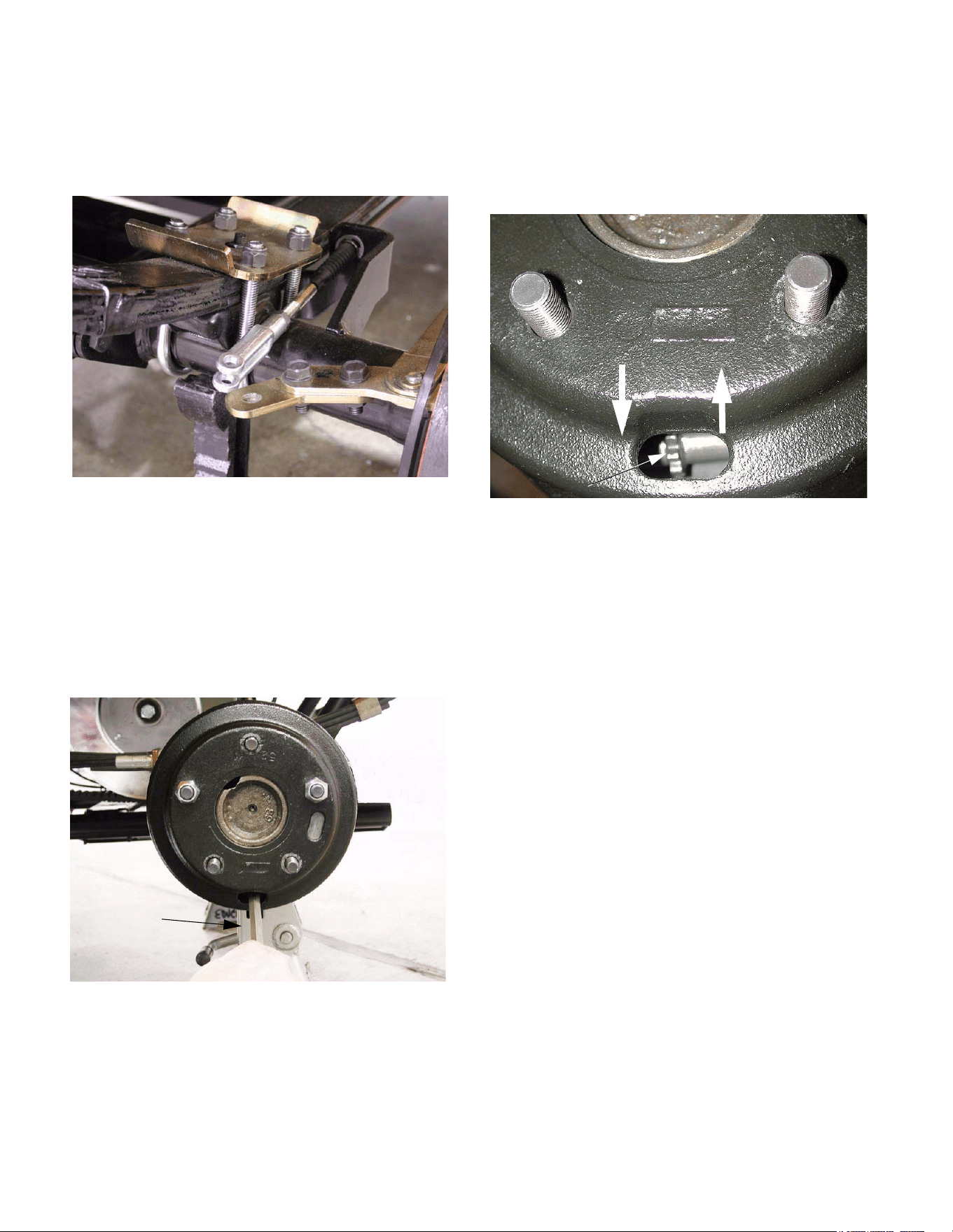
4.6. Position the access slot in the drum at the 6 o-
clock position, so that a brake adjuster spoon or
flat blade screwdriver can be inserted to reach
the star wheel on the brake adjuster.
4.7. Set the adjuster so there is slight drag on the
brake drum when turned by hand. Then adjust
until no drag is present. At this point, play
should be absent from the actuator.
See Figure 4.7.
4.8. Repeat the process for the second brake, and
proceed with the brake linkage adjustment.
Figure 4.4
Figure 4.5
Flat blade
screw driver
Figure 4.7
Loosen Tighten
Star Wheel
Big Country 4 x 2
9
BRAKE LINKAGE ADJUSTMENT:
4.9. Remove the fasteners that hold the hood closed,
and open or remove the hood if it is not already
open or removed.
4.10. Drop the clevis pins into place, securing each
brake cable clevis to the brake actuator exten-
sion arm.
NOTE: It is important that both clevis pins be in
place during adjustment because there is inter-
play between the left and right brake cables
through the equalizer bar.
4.11. Loosen each jam nut using a 1/2” wrench.
See Figure 4.11.
4.12. Adjust the brake cable by threading the clevis up
or down the threaded end of the brake cable to
lengthen or shorten the cable.
NOTE: The unthreaded part of the brake cable
end may be gripped with channel locks or a pair
of vice grips to prevent cable wind-up.
4.13. Adjustment is correct when there is 7/8” of free
play at the pedal before the stack of bellville
washers begins to compress, and the equalizer
brackets is horizontal.
NOTE: When adjustment is made, both brake
cables must be adjusted. This will prevent the
equalizer bar from being pulled down on one
side or the other.
4.14. Tighten the jam nut that locks the clevis on the
end of each brake cable using a 1/2” wrench.
NOTE: Confirm that there is at least 5/16” of
thread engagement between the clevis and the
cable end.
Make Fine
Adjustment Here
Figure 4.11
Clevis pin
(not secured by
cotter pin)
jam nut
4.15. Secure the clevis pins with new cotter pins when
adjustment is complete.
4.16. If more adjustment travel is needed, or if the
equalizer bracket is not level, the jam nuts at the
front of the brake cable can be adjusted to cor-
rect the situation using a pair of 7/8” wrenches.
See Figure 4.16.
NOTE: When adjusting the brake cables at the
firewall, the pedal travel will also be effected.
4.17. At rest, the pedal arm should stop against the
reinforcement plate that is welded to the firewall.
Figure 4.16
Left brake
cable
Jam Nuts
Right
brake
cable
Equalizer
bracket
Figure 4.17
Brake pedal
arm
Reinforcement
Big Country 4 x 2
10
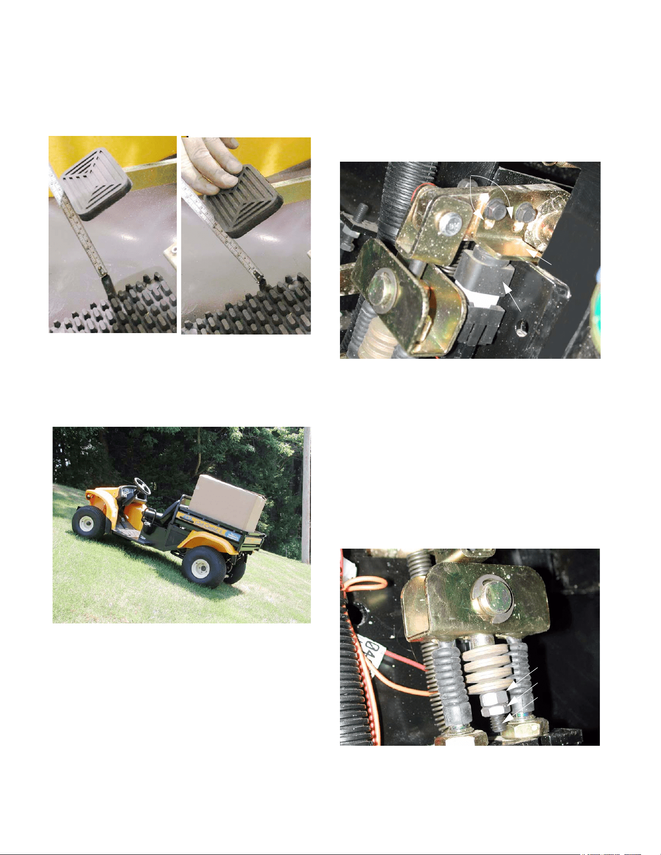
4.18. There should be 7/8” (.875”) of free-play in the
pedal before the pedal transmits movement to
the cables. Free-play is measured at the front
edge of the brake pedal pad. See Figure 4.18.
4.19. The parking brake should have sufficient holding
power to keep the vehicle from moving on a 22
degree grade with an operator in the seat and
800 lbs. in the load bed. See Figure 4.19.
4.20. When the parking brake is set, the brake switch
actuator should release the plunger on the brake
switch far enough to close the contacts within
the switch. use a 3/8” wrench to adjust the
brake switch actuator to achieve correct opera-
tion. See Figure 4.20.
NOTE: If the brake switch is not actuated, the
gear selector system will not function. If the
brake switch actuator is adjusted so that the
plunger is released before there is sufficient
pressure on the brake pedal to prevent vehicle
motion, an unsafe condition may occur.
4.21. Brake adjustments should be made using the
jam nuts on the cables, or the clevises at the
ends of the cables. The nut and jam nut on the
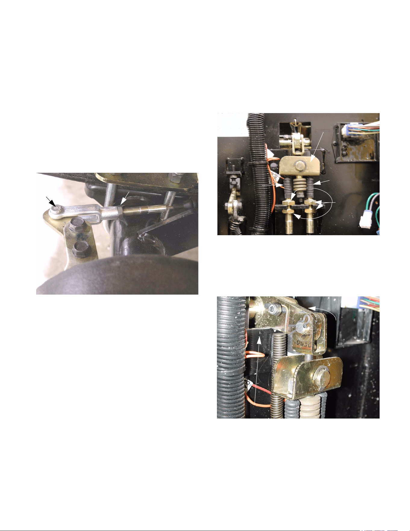
pull bolt are best left undisturbed.
See Figure 4.21.
Figure 4.18
Figure 4.19
8
0
0
L
B
Figure 4.20
switch
Brake
Brake Shown Released
Brake
switch
actuator
Adjustment
slots
Figure 4.21
Pull bolt
Jam nut
Nut
Big Country 4 x 2
11
4.22. Check to confirm that the parking brake indicator
in the instrument panel illuminates when the
parking brake is set. If it does not, it may be
necessary to adjust the parking brake switch.
See Figure 4.22.
NOTE: The parking brake switch is separate
from the brake switch.
4.23. Perform an operational test as described in the
“Operational Test” section of this manual, in a
safe area that is free of traffic, hazards, and
obstacles. Correct any brake performance
issues before returning the Big Country 4 X 2 to
service.
Figure 4.22
Parking Brake Switch
Parking brake rod
Parking brake arm

Big Country 4 x 2
12

13
1. ENGINE /TRANSMISSION CRADLE:
DESCRIPTION
The engine and transaxle are supported by a single
structure that pivots on a “dogbone” link that connects
the front of the cradle to the frame. The cradle and
transaxle function as the Big County’s rear suspension.
The engine must be held in a stable position in relation
to the transaxle, in order to maintain tension on the
drive belt. The engine is mounted to the cradle, and
moves with the suspension.
2. “DOGBONE” LINK ASSEMBLY
2.1. Make a visual inspection of the link assembly at
each engine oil change interval (200 hrs), or if
any clunking noise is noticeable from the joint.
2.2. The joint consists of a metal body with two rub-
ber bushings. The bushings allow the cradle to
swing up and down, and to pivot.
2.3. The life of the bushings will vary with tempera-
ture and severity of usage.
2.4. The joint can be replaced without removing the
cradle.
NOTE: The bolt and nut connecting the link to
the frame are SAE. The bolt and nut connecting
the cradle to the link are metric.
3. TRANSAXLE MAINTENANCE
3.1. Brake system maintenance is covered sepa-
rately in the Brake System section of this man-
ual.
3.2. The electrically controled, vacuum actuated gear
selector system is covered in the Gear Selector
section of this manual.
3.3. Lubrication intervals: Change the oil in the
transaxle after the first 50 hrs. of use. After this
break-in service is performed change the tran-
saxle oil every 24 months or 500 hrs. of use.
3.4. If the oil in the transaxle becomes contaminated,
change it immediately
3.5. To drain the oil from the transaxle, remove the
hex-head plug that is located at the bottom of the
left side of the transaxle housing, directly below
the left axle tube.
NOTE: Clean the area surrounding the drain
plug before removal.
3.6. Check the oil level in the transaxle every 100
hrs. of use. If any leakage is evident, check the
level more frequently until the Big Country 4 X 2
can be taken to an authorized Cub Cadet dealer
for repair.
4 X 2 Drive Package: Dana Transaxle
4 X 2 Drive Package: Dana Transaxle
14
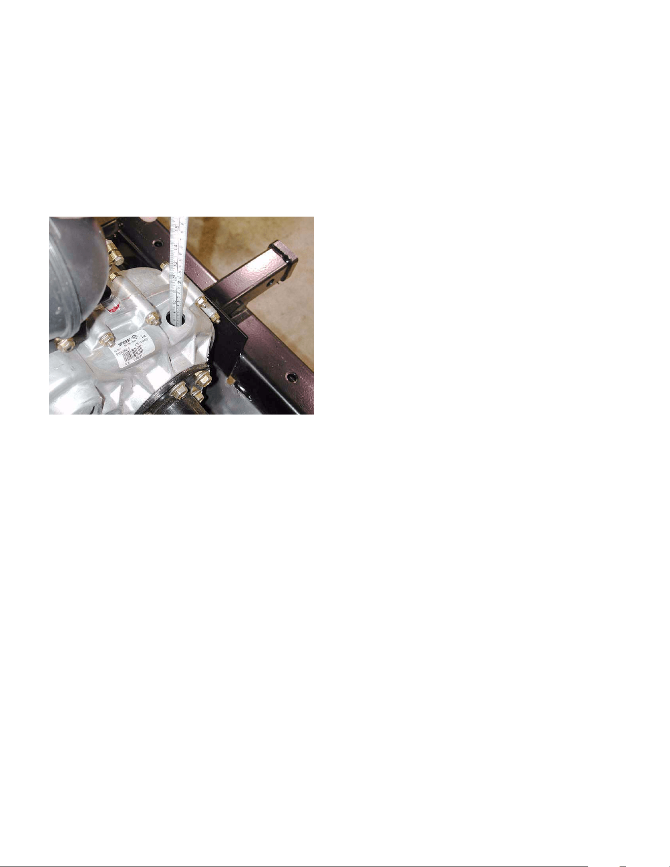
3.7. The amount of oil in the transaxle is 20 - 24
fl.oz. The level can be checked by removing the
black rubber cap visible on the top surface of the
transaxle housing, roughly in line with the axle
tubes. A clean steel rule, or improvised dipstick
should indicate the presence of oil 4 1/2“ (11.5
cm) down from the top surface of the transaxle
housing adjacent to the hole. The depth of the
oil in the housing should be 1 3/4” (4.5 cm).
See Figure 3.7.
NOTE: Clean the area surrounding the rubber
plug prior to removal.
3.8. Lubrication type: For their transaxles, Dana
recommends SAE30 engine oil or 80W-90 gear
lube. This transaxle does not contain bronze
gears, so GL4 is a suitable grade if 80W-90 is
used. Cub Cadet Hydraulic Drive System Plus
(P/N 737-3121) is a suitable premium alterna-
tive.
3.9. Cleaning: The transaxle dissipates heat through
the housing. Accumulation of dirt will result in
higher operating temperatures and shortened
service life.
3.10. Corrosive substances such as salt spray and
chemicals found in some commercial detergents
and in fertilizers should be rinsed off immedi-
ately.
3.11. Do not direct a pressure washer at any seams,
joints, seals, vents, or plugs in the transaxle
housing.
3.12. There is a vent at the highest point in the hous-
ing. It must be kept free of blockage.
4. TRANSAXLE REMOVAL
The entire drive package and cradle can be removed
from the Big Country 4 X 2 as an assembly if the tech-
nician has reason to do so. If the transaxle is to be
repaired or replaced, the most direct method is to
remove it from the cradle without removing the cradle
from the frame.
NOTE: All of the shock absorber fasteners are
metric.
Figure 3.7
15
1. DESCRIPTION OF THE GEAR SELECTOR
SYSTEM:
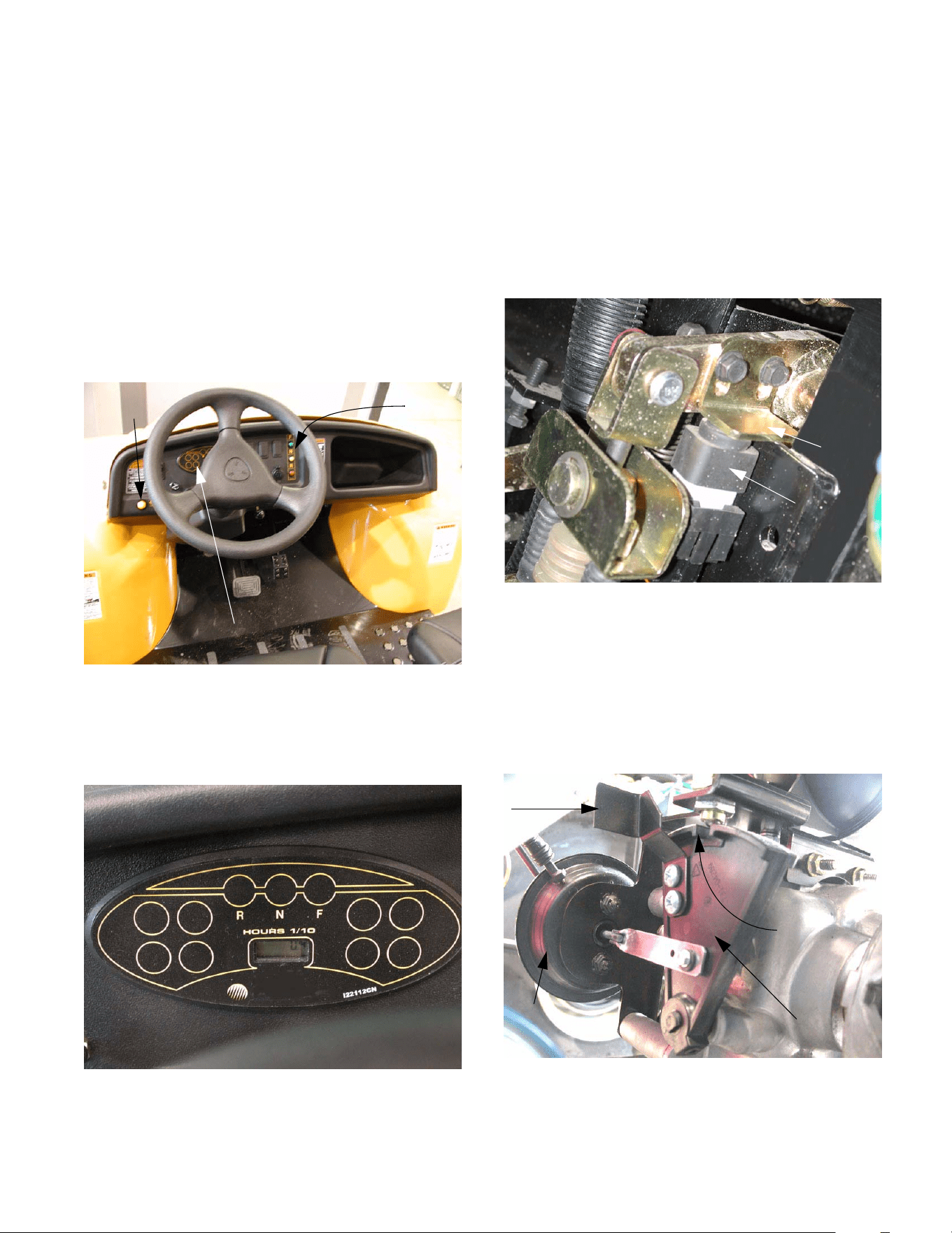
1.1. The gear selector on the 4 X 2 Utility Vehicle is
electronically controlled and vacuum actuated.
The operator selects the desired gear by push-
ing one of three buttons on the dashboard.
The operator engages and disengages the dif-
ferential lock using a yellow button to the left of
the steering wheel. See Figure 1.1.
1.2. A corresponding light on the instrument panel
confirms the selection, or flashes a trouble code
in the event of a malfunction. See Figure 1.2.
Figure 1.1
Gear
selector
buttons
Differential
lock button
Instrument panel
Figure 1.2
Detail of the instrument panel
1.3. The brake switch is tied into the gear selector
circuitry. The vehicle will not shift gears if the
brake pedal is not depressed far enough to actu-
ate the switch or if the switch actuator is out of
adjustment. See Figure 1.3.
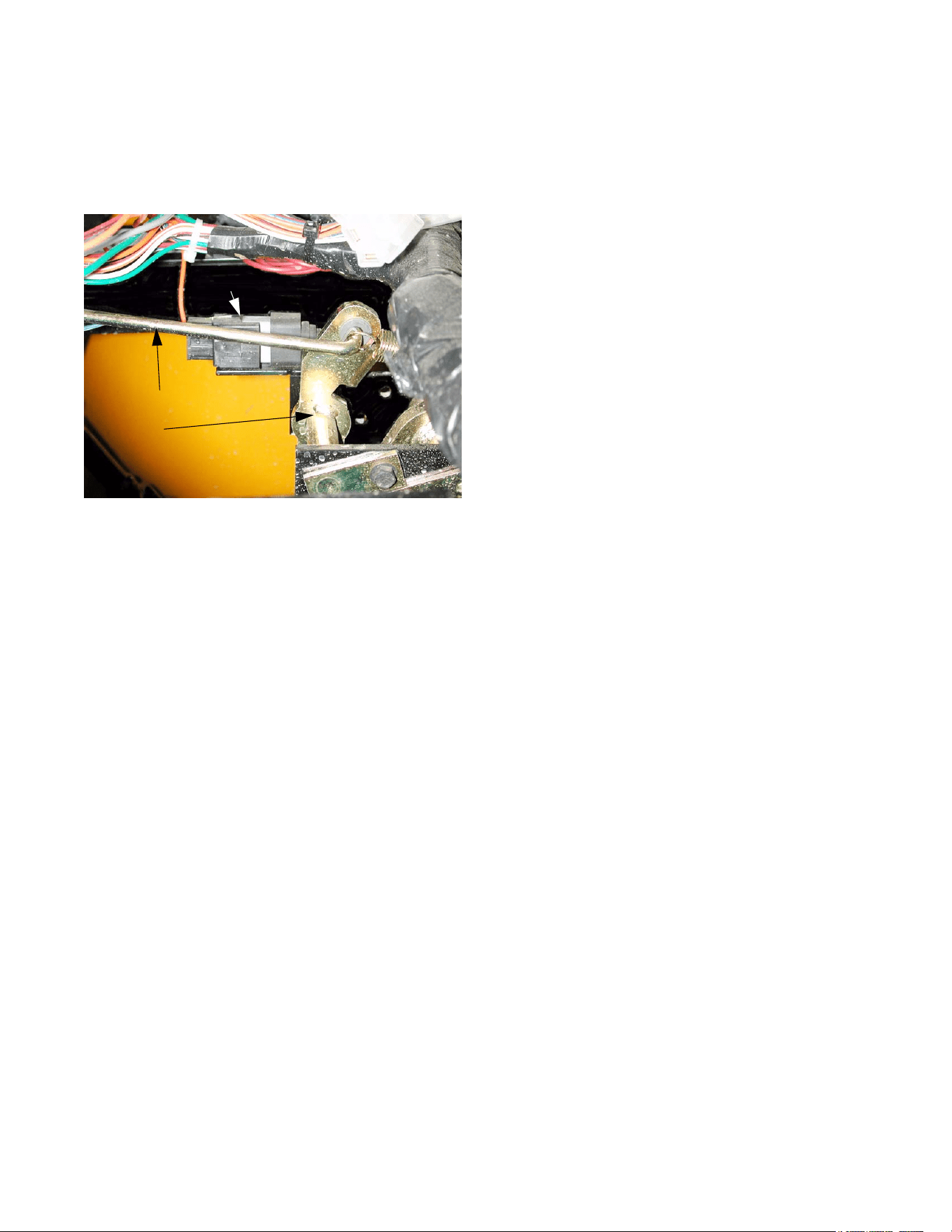
1.4. The neutral switch, mounted on the transaxle,
above the Shift Wedge, confirms the position of
the shift wedge. A detent in the shift wedge
moves a contact roller in the neutral sensor
when the shift wedge moves, generating a signal
that goes to the electronic shift module (ESM).
See Figure 1.4.
Figure 1.3
Brake
switch
Adjustable
brake
switch
actuator
Figure 1.4
Shift wedge
Notch (neutral)
Manual
over-ride
Vacuum actuator
4 X 2 Gear Selector
4 X 2 Gear Selector
16
1.5. The electronic shift module (ESM) processes
control inputs from the brake switch, neutral sen-
sor, and the gear selector buttons on the dash-
board. It figures out which way to move the
shifting wedge to engage the desired gear. If a
button is pushed, and the brake pedal is
depressed, the ESM energizes the solenoids
that control the vacuum to the servo that moves
the shifting wedge. The ESM is mounted on the
firewall, next to the brake pedal arm.
See Figure 1.5.
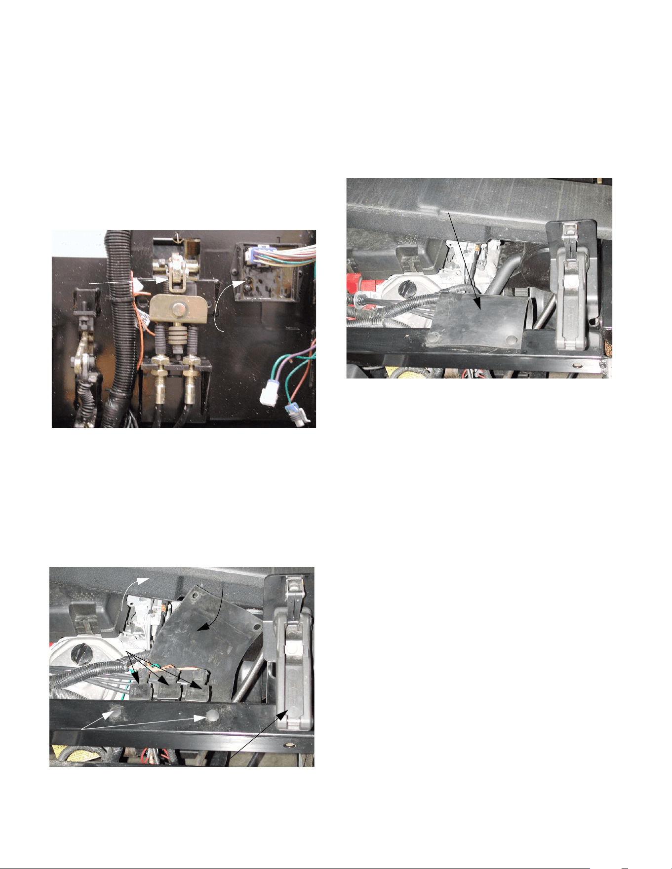
1.6. The solenoids are electrically operated valves
that direct vacuum to one side of the servo or the
other. The movement of the servo (vacuum actu-
ator) is what moves the shift wedge. They are
mounted to the upper frame member at the for-
ward corner of the engine compartment, to the
left hand side. See Figure 1.6.
1.7. The solenoids are covered by a protective rub-
ber sheet. To reach them, remove the two wing-
nuts that secure the plenum to the upper cross-
member, and carefully move the plenum aside.
The cover can be “unbuttoned” from the tow top
fasteners, and folded out of the way.
See Figure 1.7.
1.8. The vacuum line marked with a red dot car-
ries vacuum that moves the actuator in the
“forward” direction. This may be a movement
from neutral to forward, it may be a movement
from reverse to neutral, or it may be a movement
from reverse, past neutral to forward. The ESM
keeps track of which direction it is told to move
the actuator and whether or not the detent in the
shift wedge has passed the neutral sensor. The
vacuum line with the red dot should connect to
the solenoid nearest the outside of the vehi-
cle. That solenoid (forward) has one red wire
and one yellow wire with a black trace.
1.9. The vacuum line marked with the green dot
carries vacuum that moves the actuator in
the “reverse” direction. This may be a move-
ment form Neutral to Reverse, it may be a move-
ment form Forward to Neutral, or it may be a
movement from Forward, past Neutral, to
Reverse. The vacuum line with the green dot
should connect to the middle solenoid. The
middle (reverse) solenoid has one red wire
and one orange wire.
Figure 1.5
Electronic
Shift
Module
Brake
pedal
arm
Figure 1.6
Bed latch
Plenum
(removed)
SOLENOIDS
Protective
cover
Push-in fasteners
Figure 1.7
Protective cover
in place over vacuum solenoids
4 X 2 Gear Selector
17
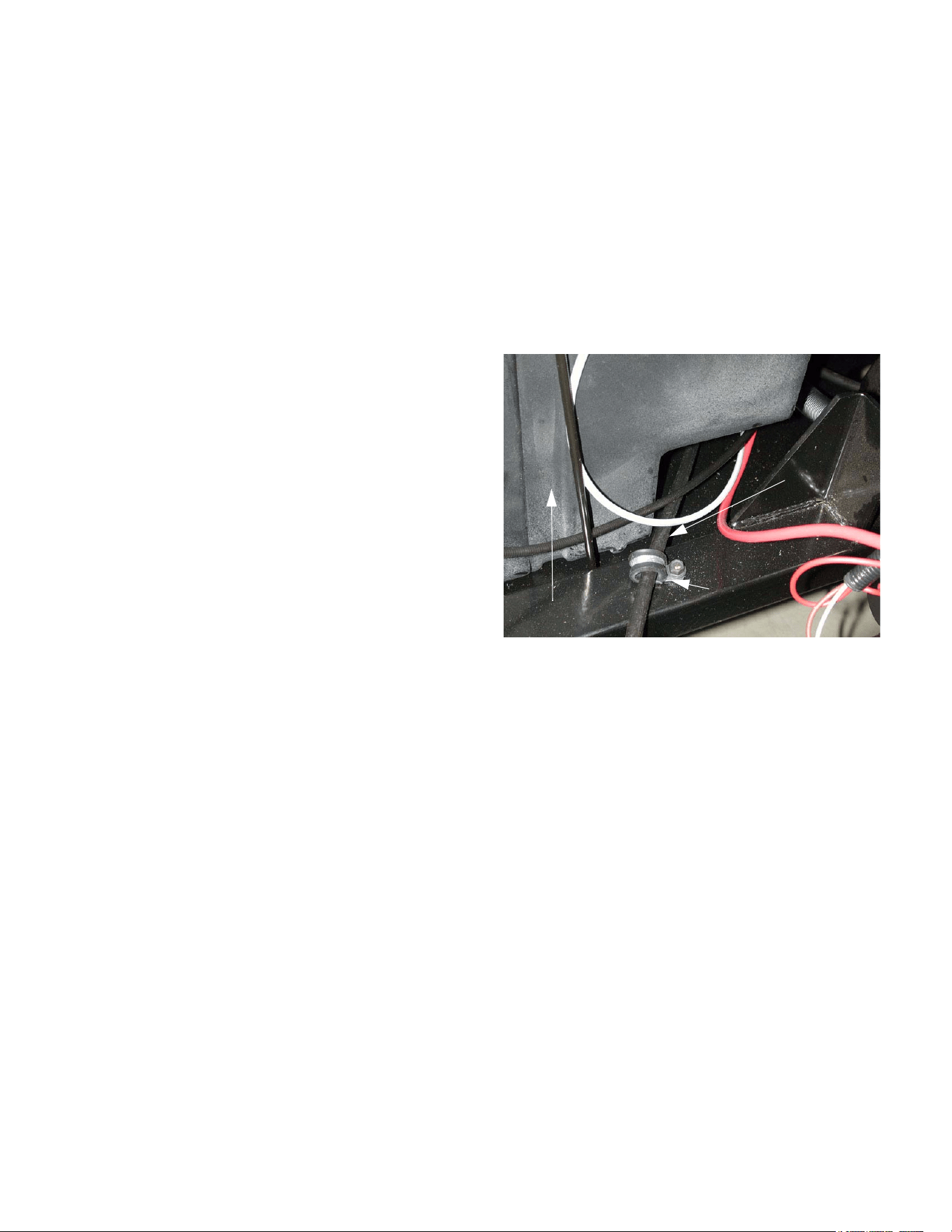
1.10. The vacuum line marked with a blue dot pro-
vides vacuum to the actuator that controls
the differential lock. The differential lock is
engaged by a separate vacuum actuator. The
differential lock is disengaged by spring action
when two conditions are met: (1) The differential
lock solenoid is not activated and (2) If the differ-
ential lock was previously engaged, the speed of
the rear wheels is equal. The vacuum line with
the blue dot should connect to the inner sole-
noid. The inner (differential lock) solenoid has
one yellow wire with a white trace and one
green wire. See Figure 1.10.
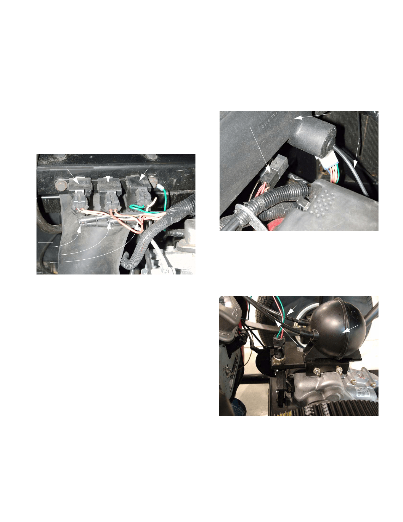
1.11. Solenoid operation is as follows:
• A vacuum manifold connected to the vacuum
reservoir connects to the lower fitting on all three
solenoids.
• The color-marked elbows connect to the upper
fitting on each solenoid. The vacuum lines that
are connected to each solenoid by a color-
marked elbow lead from the solenoid to an actu-
ator.
• The orange and white wire provides power to the
forward and reverse solenoids. It should be
“hot” whenever the key switch is on. The sole-
noids are controlled by the presence or lack of
ground at the other wire that connects to each.
• The differential lock solenoid has a constant
ground, provided by the green wire. Presence of
current at the yellow and white wire triggers the
differential lock solenoid.
• When energized, each solenoid will connect
vacuum from the manifold (reservoir), through
the color marked elbow, to its actuator.
Figure 1.10
Dots:
red
green
blue
Forward Reverse Differential
solenoid lock solenoid
• When the solenoid is de-energized, it provides a
vent to the atmosphere to release the pull on the
diaphragm.
NOTE: Because the differential lock actuator
only pulls in one direction, the vent from the
actuator is located in the plenum.
See Figure 1.11.
1.12. The vacuum reservoir (accumulator) holds a
reserve supply of vacuum to operate the actua-
tor in low engine vacuum conditions. It is
mounted to the top of the transaxle.
See Figure 1.12.
NOTE: One vacuum line connects the intake
manifold to the vacuum reservoir. The other vac-
uum line connects the vacuum reservoir to the
solenoids.
Figure 1.11
Plenum
Starter relay Vent tube for
differential
lock actuator
Figure 1.12
Vacuum (to solenoids)
Vacuum
reservoir
Vacuum
(from intake manifold)
4 X 2 Gear Selector
18
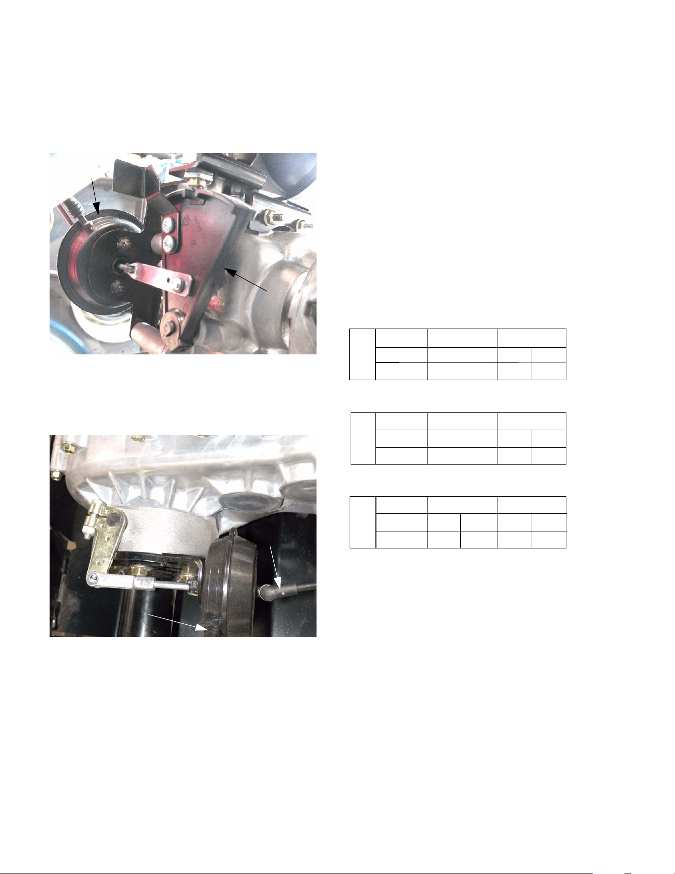
1.13. The forward / reverse actuator is connected to
the shift wedge. Depending on which side of the
actuator vacuum is provided to, the actuator
moves the shift wedge in one direction or the
other. See Figure 1.13.
1.14. The differential lock actuator is mounted lower
and farther back on the transaxle.
See Figure 1.14.
2. SELF DIAGNOSTICS
2.1. In the event of system malfunction, refer to the
fault code list.
2.2. If the Big Country does not shift properly, the
ESM will let the operator know there is a prob-
lem using the following table of fault codes.
Once the operator selects a gear, the instrument
panel will illuminate a gear light, or a combina-
tion of gear lights. DO NOT PRESS THE
ACCELERATOR UNTIL THE GEAR
SELECTED IS VERIFIED ON THE INSTRU-
MENT PANEL. These lights can be used to
determine if the vehicle shifted properly, or if
there is a shifting issue. The letter on the far left
represents the gear the vehicle was in prior to
shifting:
* - Indicates the lights will flash for 5 seconds and an
audible tone will sound. During that time a shift will not
be allowed by the ESM. Once the lights stop flashing
the ESM will allow for shifting.
Example - The vehicle was in reverse (look at row
starting with "R"). The gear selected was forward (look
at "F" in "Gear Selected" row). The "Light Code"
flashed on the instrument panel is "RF", which corre-
sponds with "Fault code 3". Looking up "code 3" in the
"Fault Codes Defined" section will list the potential
problems.
Figure 1.13
Shift Wedge
Vacuum
actuator
(servo)
Figure 1.14
Vacuum from
solenoid
Vent line to plenum
R
Gear Selected
Light Code
Fault Code
N
F
N
FN*
FRF*
None
2
None
3
F
Gear Selected
Light Code
Fault Code
R
N
N
RN*
R
RF*
13
None
None
N
Gear Selected
Light Code
Fault Code
F
R
R RN*
F
FN*
None
1
None
2

4 X 2 Gear Selector
19
3. TERMS & DEFINITIONS -
• ESM - Electronic Shift Module
• Neutral Switch - in the neutral position the
switch is normally closed (NC).
• Shift Wedge - this is a wedge shaped mechani-
cal part that actuates the Neutral Switch depend-
ing on the gear selected. The void portion of the
wedge is neutral.
• Closed Circuit Failure - the contacts in the
Neutral Switch will stay closed when the shift
wedge is in forward or reverse position. This will
occur if the shifting wedge is not contacting the
Neutral Sensor properly.
• Open Circuit Failure - the contacts in the Neu-
tral Switch will stay in the open position even
when the contact roller passes the void in the
shifting wedge. This will occur if the contact
roller of the sensor is stuck inside the sensor
housing or if the wires leading to the sensor are
cut/disconnected.
NOTE: To determine the failure mode, it is nec-
essary for the ESM to remember the original
state of the transmission gear, the gear that was
selected, and the state of the indicator lights.
NOTE: The ESM should automatically return the
shift wedge to the neutral position if the key
switch is turned off with the vehicle in gear.
FAULT CODES DEFINED
Code 1: "REVERSE" and "NEUTRAL" lights flash
Action A - Vehicle is in "FORWARD" and operator
attempts a shift to "NEUTRAL"
• This lets the operator know the vehicle was sup-
posed to go to neutral, but probably ended up in
reverse. The vacuum actuator probably shifted
the transmission into reverse because the signal
to stop at neutral was not present. However, it
may not have shifted out of forward if there was
mechanical binding, or loss of vacuum.
Action B - Vehicle is in "NEUTRAL" and operator
attempts a shift to "REVERSE"
• This lets the operator know the vehicle was sup-
posed to go to reverse and it probably did, but it
was not verified because the contacts in the
Neutral Switch never opened (due to mechanical
binding or a damaged switch).
Code 2: “FORWARD” and “NEUTRAL” lights flash
• Action C - Vehicle is in "REVERSE" and opera-
tor shifts to "NEUTRAL"
• This lets the operator know the vehicle was sup-
posed to go to neutral, but probably ended up in
forward. The vacuum actuator probably shifted
the transmission into forward because the signal
to stop at neutral was not present. However, it
may not have shifted out of reverse if there was
mechanical binding, or loss of vacuum.
• Action D - Vehicle is in "NEUTRAL" and operator
attempts a shift to "FORWARD"
• This lets the operator know the vehicle was sup-
posed to go to forward and it probably did, but it
was not verified because the Neutral Switch con-
tacts never opened (due to mechanical binding
or a damaged switch).
Code 3: “FORWARD” and “REVERSE” lights flash
Action E - Vehicle is in “FORWARD” or “REVERSE”
and the operator shifts to the opposite direction
This lets the operator know the vehicle was supposed
to shift to the opposite direction and it probably did,
but the module was not able to verify. this may have
occurred because the neutral switch is damaged, or
there is mechanical binding, or loss of vacuum.
CAUTION: If the vehicle is shut off under a fault
condition it should return automatically to neu-
tral. If the vacuum lines are defective, the unit
exhibits mechanical binding, or if the neutral
switch is damaged the unit will not return to neu-
tral. When attempting to start the vehicle, either
all or none of the gear indicators will be illumi-
nated. In those instances, before the vehicle will
start again, the contacts in the Neutral Switch
must be closed AND the vehicle will have to be
manually shifted into "NEUTRAL".
4 X 2 Gear Selector
20
4. GEAR SELECTOR SYSTEM DIAGNOSIS
EXPLANATION OF METHODOLOGY:
• The gear selector system relies on two sub-sys-
tems (electrical and vacuum) to work properly. If
either sub-system fails, the entire system will not
operate correctly.
• A complete decision tree for diagnosis would be
unwieldy because of the number of variables
involved.
• The procedure as it is written here covers the
testing of each component in the system, and
should be a suitable guide for a competent tech-
nician who is not specifically familiar with the Big
Country gear selector system. The process:
1. Basic checks to identify obvious problems
and help define more in-depth problems.
2. Vacuum tests to see if the vacuum system
is responding to electrical inputs.
3. Electrical tests
• As technicians become familiar with this system,
they will be able to draw on their experience to
expedite the diagnostic process. The entire pro-
cess may not be necklaces for every malfunc-
tion.
BASIC CHECKS:
4.1. Begin by test running Big Country vehicle to
confirm the problem. This may be done with the
vehicle on jack stands.
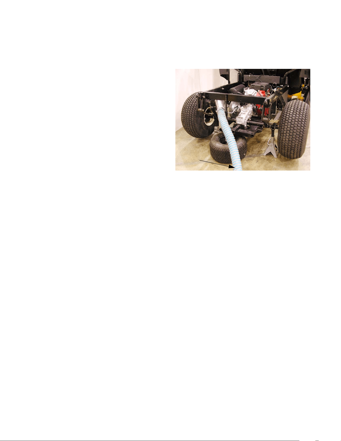
4.2. Safely lift and support the rear of the vehicle on
jackstands so that the rear wheels are clear of
the ground.
4.3. Raise the bed so that the transmission is visible
and accessible. Look at the position of the shift
wedge to confirm that the vehicle is in neutral.
NOTE: The bed may be removed entirely if the
technician finds it convenient.
4.4. Insure that no unsafe conditions will be created
by running the vehicle and operating the drive
system. See Figure 4.4.
4.5. Test run the vehicle, checking all modes of trans-
mission operation.
NOTE: Perform tests at idle speed (1,250 to
1,400 RPM).
4.6. If the dash panel flashes “self diagnostic” sig-
nals, use the code descriptions in the “Fault
Codes Defined” section of this manual to help
identify the problem.
4.7. If the starter motor will not respond to the key
switch, check the neutral switch as described in
the “Gear Selector Electrical Diagnosis” section
of this manual.
4.8. If the transmission fails to shift in response to the
control button on the dashboard, turn the engine
off, and move the shift wedge by hand to check
for mechanical bind.
NOTE: It may be necessary to rotate the driven
clutch or the wheels slightly to engage forward
(F) or reverse (R) gear.
NOTE: A mechanical bind may indicate an inter-
nal transmission problem, not a gear selector
problem.
Figure 4.4
Exhaust
vented
Vehicle safely
Clear work area
supported
4 X 2 Gear Selector
21
4.9. If the transmission fails to shift in response to the
control buttons on the dashboard, and the shift
wedge can be operated by hand with the engine
off, check the operation of the transmission.
• Manually place the shift wedge in neutral.
• Set the parking brake.
• Start the engine.
CAUTION: Keep well clear of any rotating com-
ponents.
CAUTION: Do not reach over any rotating com-
ponents or place yourself in a position that may
cause you to come into contact with rotating
components.
CAUTION: Do not wear loose fitting clothing that
may tangle in rotating components.
• Manually shift the transmission into each motion
gear (forward and reverse), and observe the
torque reaction of the transmission.
• Once a motion gear is engaged, it is possible to
return to the operator’s position and release the
parking brake to check wheel motion.
• After wheel motion is checked, set the parking
brake, turn off the engine, and return the shift
wedge to neutral position.
• This procedure may be repeated for the other
motion gear.
NOTE: Unless the differential lock is engaged (if
the vehicle is equipped with one) or the parking
brake is set, with one of the wheel’s brakes dis-
abled, the wheels may not rotate in the expected
direction because of normal differential action.
• With the parking brakes released, and the shift
wedge in neutral, spin the wheels. If there is
drag or unusual noises a problem may exist
within the transaxle or brakes.
4.10. Follow the functional test with a visual inspec-
tion of the gear selector system. After it is con-
firmed that the problem lies in the gear selector
system rather than the transaxle itself, the com-
ponents of the gear selector system should be
examined.
NOTE: Refer to the “Description of the Gear
Selector System” section of this manual for pic-
tures and descriptions of the components to be
inspected.
4.11. Remove the two wing nuts that secure the hood,
and open the hood.
4.12. Check to see if the arm on the brake pedal is
releasing the plunger far enough to close the
contacts within the switch when the pedal is
pressed.
4.13. If an audible click is not heard from the switch
when the brake pedal is pressed, adjust the
switch (and the brakes if necessary) as
described in the “Brake Adjustment” section of
this manual.
4.14. Check the brake switch connection for tightness,
and check the condition of the wires leading to
the switch. Power passes through the brake
switch to reach the buttons on the dashboard.
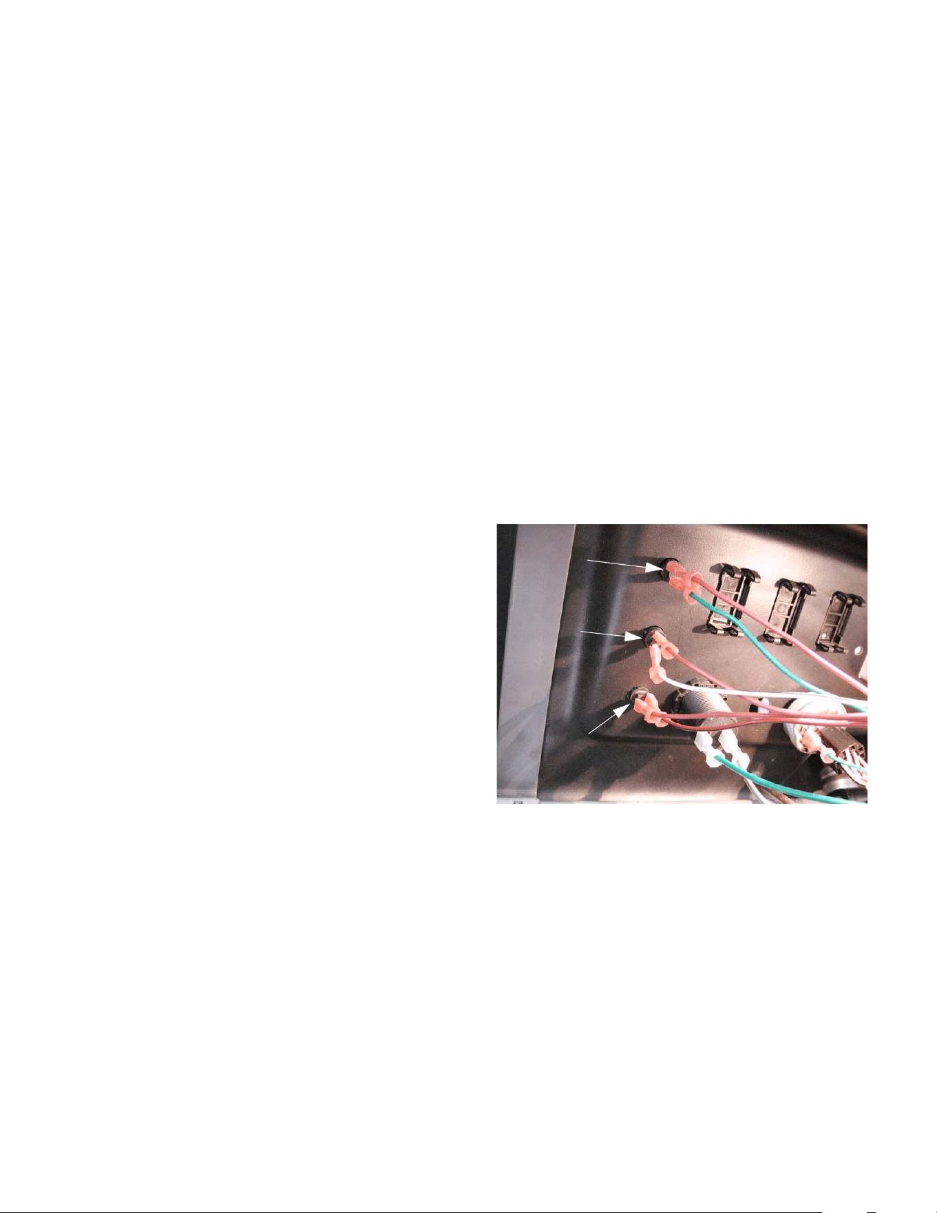
4.15. The back side of the buttons that control the
gear selector are visible with the hood open.
Check the connections for tightness and check
the condition of the wires leading to each button.
See Figure 4.15.
Figure 4.15
Forward button
Neutral button
Reverse button
4 X 2 Gear Selector
22
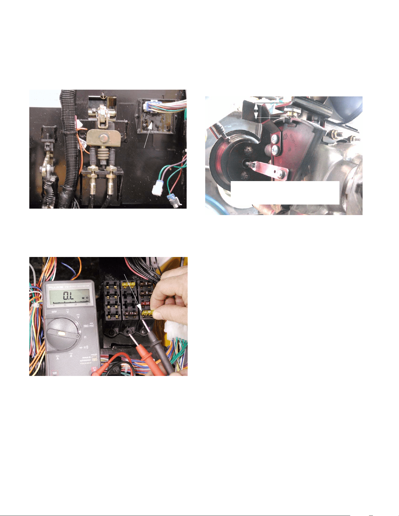
4.16. The ESM is visible on the firewall next to the
brake pedal arm. Check the harness connection
to the ESM for tightness, and check the condi-
tion of the wires leading to the ESM.
See Figure 4.16.
4.17. Check the condition of the fuse that provides
power to the gear selector system.
See Figure 4.17.
4.18. The neutral switch is visible above the shift
wedge. Check the connection for tightness, and
check the condition of the wires leading to the
neutral sensor.
4.19. Check the operation of the neutral switch. The
switch is normally closed. The contact roller
should move freely, breaking continuity when
the roller is pressed upward by the shift wedge.
Adjust or replace if necessary. See Figure 4.19.
4.20. Check the tightness of the electrical connections
to the vacuum solenoids, and check the condi-
tion of the wires leading to the solenoids.
Figure 4.16
Electronic
Shift
Module
Figure 4.17
Fuse that protects the ESM
Figure 4.19
.566” to.610 (9/16” to 5/8”) from the
bottom of the hex to the top of the
shift wedge.
4 X 2 Gear Selector
23
5. VACUUM TESTS
NOTE: The vacuum system is robust enough to
function reasonably well, even with substantial
leaks. The primary symptom of a leaky system
will be failure to return to neutral when the vehi-
cle is turned-off in gear.
5.1. With the engine off and the choke closed,
release the clips that secure the air filter cover.
Remove the air filter cover and air filter.
5.2. Remove the air filter base and air horn baffle
using a socket wrench (10mm socket and 8mm
socket).
5.3. Trace the vacuum line from its source on the
intake manifold to the vacuum actuator. Look for
loose connections or damaged vacuum line.
See Figure 5.3.
5.4. The vacuum lines lead from the intake manifold
to the vacuum reservoir. From the reservoir, a
line goes up to both vacuum solenoids. From
the solenoids, a separate line leads to each side
of the vacuum actuator on the transaxle.
5.5. Correct any potential problems that are found
during the visual inspection.
5.6. Install the air filter and cover.
Figure 5.3
Intake manifold
Line to
reservoir
Vacuum port
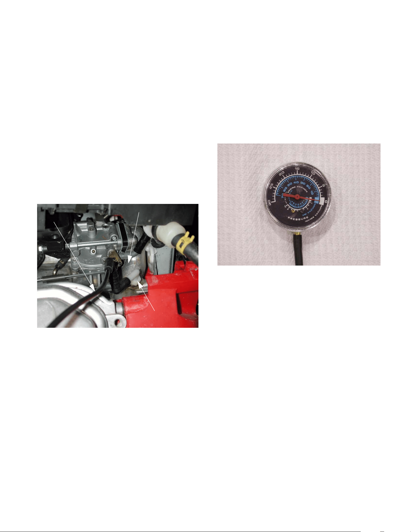
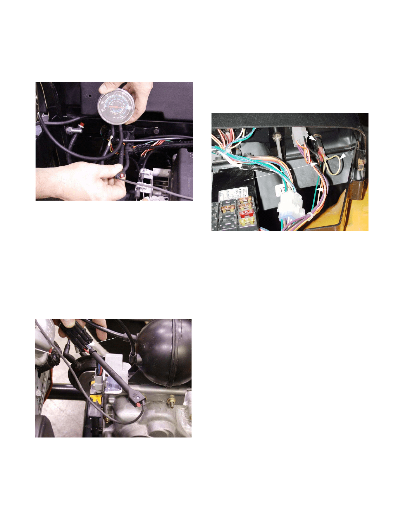
5.7. After a visual check for obvious problems, check
for the presence of vacuum.
NOTE: A vacuum gauge that reads from 0 to 30
inches of mercury (HG) will be necessary to
complete this test. These instruments are com-
monly available at a reasonable price. They are
sometimes combined with low pressure pres-
sure gauges. A U-tube manometer, as is some-
times used to check crankcase pressure is not
suitable. See Figure 5.7.
5.8. A quick check can be made by simply discon-
necting the vacuum line from the engine at the
accumulator. Presence of vacuum can be felt
against a finger placed over the end of the line.
When the end of the line is open, the engine
note will become unsteady and the engine may
hunt for idle speed.
NOTE: All vacuum connections on the 4X2 are
secured with a light adhesive. After repairs are
completed, if a connection is not as secure as it
was previously, replace it or secure it with a
sparing amount of weather strip adhesive.
Figure 5.7
Vacuum gauge scale:
0 to 30 inches of
mercury (HG)
4 X 2 Gear Selector
24
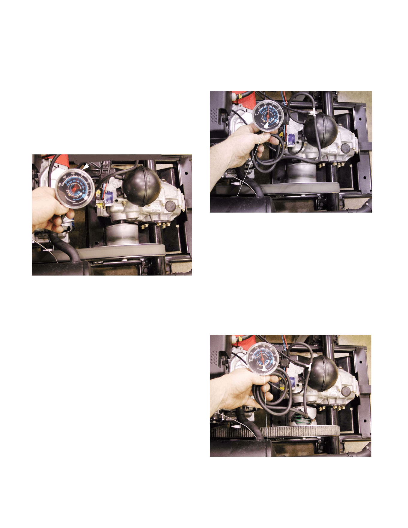
5.9. If a vacuum gauge is connected by T-fitting at
the reservoir (accumulator) end of the vacuum
line from the intake manifold, the following
readings should occur: See Figure
5.9.
• Idle speed: pulsing needle 7 - 18 in. HG.
• 2500 RPM: steady between 15 - 22 in. HG.
(usually 17 - 18 in. HG.)
• Over-run: highest reading > 30 in. HG.
• Engine Off: vacuum falls to 0.
NOTE: If the vacuum level is low, it may be an
engine problem such as low compression or a
blocked exhaust system.
NOTE: If there are no engine problems and the
vacuum is low, the most common cause will be
leaky vacuum lines or fittings. To check for this,
dead-head the vacuum gauge to the line leading
to the manifold. If the vacuum level improves,
there are leaks in the system.
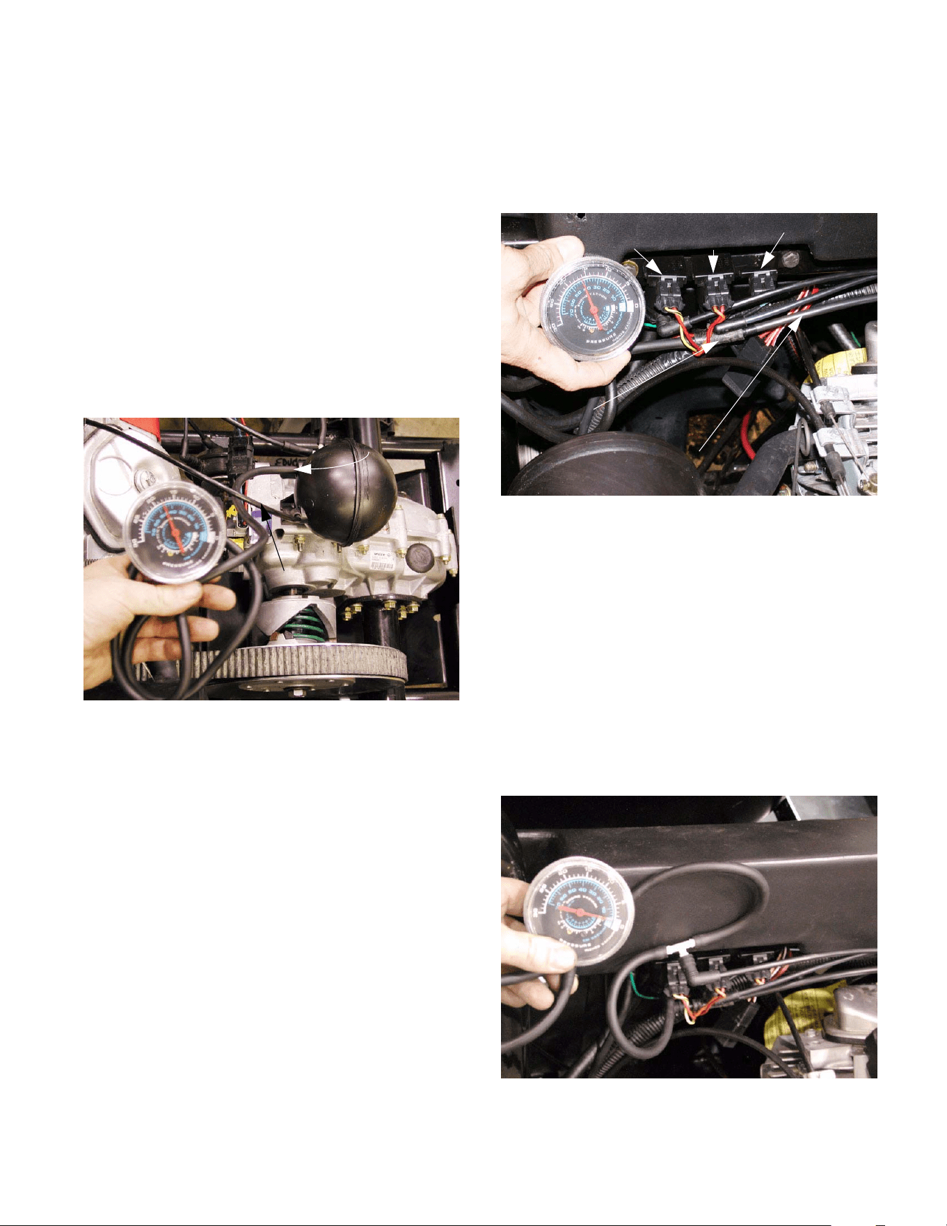
5.10. If a vacuum gauge is connected by T-fitting to
the line that leads from the accumulator to
the solenoid valves, the following readings
should occur: See Figure 5.10.
• Idle speed: steady needle 15”-22” HG.
(usually 17”-18” HG.)
• 2500 RPM: steady needle 15”-22” HG.
(usually 17”-18” HG.)
• Over-run: steady needle 15”-22” HG.
(usually 17”-18” HG.)
Engine Off: vacuum will slowly bleed down to 0 over
the course of 10 - 15 minutes. In this time it will be pos-
sible to shift gear several times until the vacuum level
falls below about 7” HG. See Figure 5.10.
Figure 5.9
Pulsing needle at idle
Figure 5.10
Steady needle at idle
Figure 5.10
vacuum after the engine is stopped
Maintains several shifts worth of
4 X 2 Gear Selector
25
NOTE: The vacuum reaction is different from
one side of the reservoir to the other because
there is a check valve built into the reservoir.
The reservoir also acts as a damper, smoothing
out the vacuum levels variations and pulses.
NOTE: If the lines are reversed on the reservoir,
no vacuum will register on the gauge.
NOTE: If vacuum bleeds down quickly, there are
leaks in the system. Isolate different portions of
the system to identify leaks.
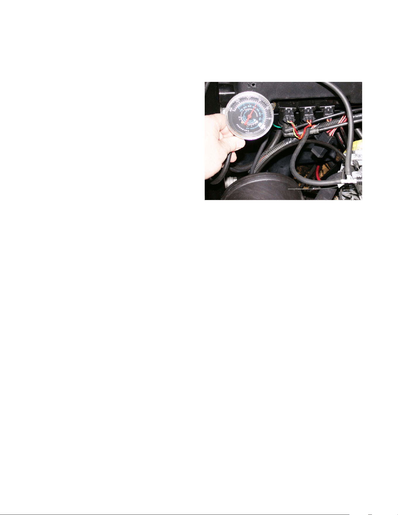
5.11. Dead-head the vacuum gauge to the outlet side
of the reservoir. If the vacuum level falls quickly,
the reservoir is leaking. See Figure 5.11.
Figure 5.11
Dead-head gauge
connection
Viscus from
intake manifold
5.12. Disconnect and plug the fittings that lead to two
of the solenoid valves. If the vacuum bleeds
down quickly, the solenoid valve that is still con-
nected is at fault. Reverse the test to confirm
the results. See Figure 5.12.
5.13. If vacuum bleeds down with all of the solenoid
valves eliminated from the system, and the res-
ervoir is not leaking: the leak lies in the line
between the valves and the accumulator.
5.14. If vacuum reaches the solenoid valves, but the
gear selector does not respond to the push but-
ton on the dashboard, check the action of the
solenoid valves.
5.15. Identify the vacuum line from the forward sole-
noid valve. Use a T-fitting to install the vacuum
gauge in-line between the solenoid and the shift
actuator (upper fitting). See Figure 5.15.
Figure 5.12
Gauge connection
Vacuum line to reservoir
Forward Reverse Differential
solenoid solenoid lock solenoid
Figure 5.15
Vacuum gauge teed-into the vacuum
line from the forward solenoid to the
shift actuator
4 X 2 Gear Selector
26
NOTE: The vacuum line from the forward sole-
noid will have a red dot on the elbow that con-
nects it to the upper fitting on the valve. The
valve itself should be controlled by two wires: (1)
Orange with white trace wire and (1) yellow with
black trace wire.
5.16. Start the engine, operate the gear selector but-
tons on the dashboard, and observe the vacuum
reading on the gauge. The readings should be
as follows:
• Neutral to Reverse:
Brief rise to roughly 5” HG., followed by return to 0.
• Reverse to Forward:
Rise to 15”-22” HG. (usually 17”-18”) and hold
steady. May pause at roughly 5 HG.
• Forward to Neutral:
Pause at roughly 5” HG., drop to 0.
• Neutral to Forward:
Rise to 15”-22” HG. (usually 17”-18” HG.) and
hold.
• Forward to Reverse:
Pause at roughly 5” HG., drop to 0.
• Reverse to Neutral:
Brief rise to roughly 5” HG. followed by return to 0.
5.17. Identify the vacuum line from the reverse sole-
noid valve. Use a T-fitting to install the vacuum
gauge in-line between the solenoid and the shift
actuator (upper fitting). See Figure 5.17.
NOTE: The vacuum line from the reverse sole-
noid will have a green dot on the elbow that con-
nects it to the upper fitting on the valve. The
valve itself should be controlled by two wires: (1)
orange with white trace wire and (1) orange wire.
5.18. Start the engine, operate the gear selector but-
tons on the dashboard, and observe the vacuum
reading on the gauge. The readings should be
as follows:
• Neutral to Reverse:
Rise to 15”-22” HG. (usually 17”-18”) and
hold steady.
• Reverse to Forward:
Brief rise to roughly 5” HG. followed by return to 0.
• Forward to Neutral:
Brief rise to roughly 5” HG. followed by return to 0.
• Neutral to Forward:
Brief rise to roughly 5” HG., followed by return to 0.
• Forward to Reverse:
Rise to 15”-22” HG. (usually 17”-18”) and
hold steady. May pause at roughly 5” HG.
• Reverse to Neutral:
Brief rise to roughly 5” HG. followed by return to 0.
Figure 5.17
Tee connection
4 X 2 Gear Selector
27
5.19. If vacuum signals vary, check the electrical sig-
nal to the vacuum solenoid (see “Gear Selector
Electrical System Diagnosis” section of this
manual).
5.20. If the electrical system is functioning properly,
replace the suspect solenoid valve.
NOTE: The most common failure modes will be
for a solenoid valve to be stuck fully open or
stuck fully closed.
5.21. If the vacuum signals are correct to this point,
but the shift wedge does not operate correctly,
and the transmission does not have any internal
problems, there may be one of the following
issues:
• The vacuum actuator may be bad.
• There may be a vacuum leak between the vac-
uum solenoid and the vacuum actuator.
NOTE: A bad vacuum actuator will seldom work
in either direction.
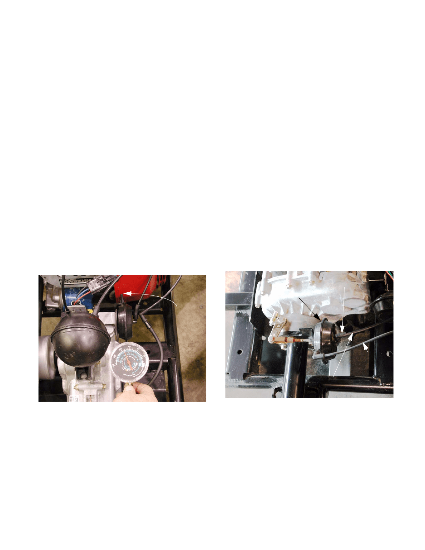
5.22. To isolate a problem that lies down-stream of the
vacuum solenoids, dead-head the gauge into
the vacuum line that connects to the forward
side of the vacuum actuator. See Figure 5.22.
5.23. Start the engine, and press the “F” button on the
dashboard.
5.24. The vacuum should rise to 15”-22” HG. (usually
17”-18” HG.).
NOTE: The “F” and “N” buttons will flash on the
control panel in the dashboard, and the shift
wedge will not move.
5.25. With any other gear selected, the vacuum level
should be 0.
Figure 5.22
Vacuum here
pulls the shift
wedge toward
forward gear
5.26. Repeat the test on the vacuum line that con-
nects to the reverse side of the vacuum actuator.
The results should mirror the results of the first
test.
5.27. If both tests work as described, the vacuum
actuator is bad.
DIFFERENTIAL LOCK ACTUATOR
5.28. Testing the vacuum signal to the differential lock
actuator is a very similar procedure. All of the
tests upstream of the vacuum solenoids apply to
all three solenoids.
5.29. Because the differential lock actuator only needs
to move in one direction, there is only one vac-
uum line leading to the actuator. The second
line is only a vent.
5.30. Teeing-in the gauge between the solenoid and
the actuator should yield a vacuum reading that
rises to 17-18 inches, and holds when the
engine is turned off. See Figure 5.30.
Figure 5.30
Vent line
Vacuum line
Differential lock
Tee-in vacuum
actuator
gauge here
4 X 2 Gear Selector
28
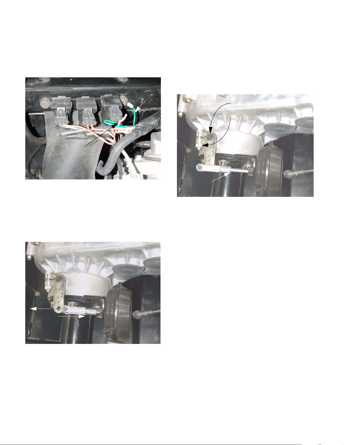
5.31. The differential lock works independently of the
gear selector, and is not controlled by the ESM.
It responds directly to the yellow button to the left
of the steering wheel. See Figure 5.31.
NOTE: The differential lock button is a back-lit
momentary contact switch. When the differential
lock is engaged, the button will light-up. The dif-
ferential lock will stay engaged, and the button
will stay lit until the button is pushed a second
time to disengage the differential lock.
6. GEAR SELECTOR ELECTRICAL SYSTEM
DIAGNOSIS.
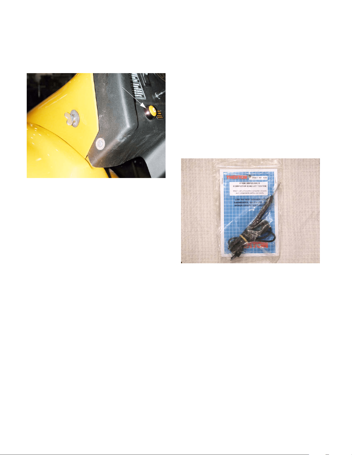
6.1. Any time a computer controlled circuit is being
checked, a high impedance circuit tester
should be used. A conventional circuit tester
simply places a light bulb in series with a ground
path from the circuit being tested. The draw
placed on the circuit by a conventional circuit
tester can damage computer circuitry such as
that used in the ESM. High impedance circuit
testers do not pass the full line current to ground,
but do pass a small portion of the line current to
ground, sense the presence of current, and light
a small LED indicator. High impedance circuit
testers are commonly available at a reasonable
price. See Figure 6.1.
NOTE: Back-probing is the best technique for
finding power at molded connections. Clip the
end of the tester lead to a good ground, and
probe the connector with the end of the tester.
6.2. If there are no signs of life in the gear selector
electrical system, check the fuse as described in
the “BASIC CHECKS” section of this manual.
NOTE: If the fuse is blown, inspect the rest of
the gear selector wiring harness to find the
source of the short that caused the blown fuse.
Figure 5.31
Differential
lock button
Figure 6.1
High impedance
circuit tester
4 X 2 Gear Selector
29
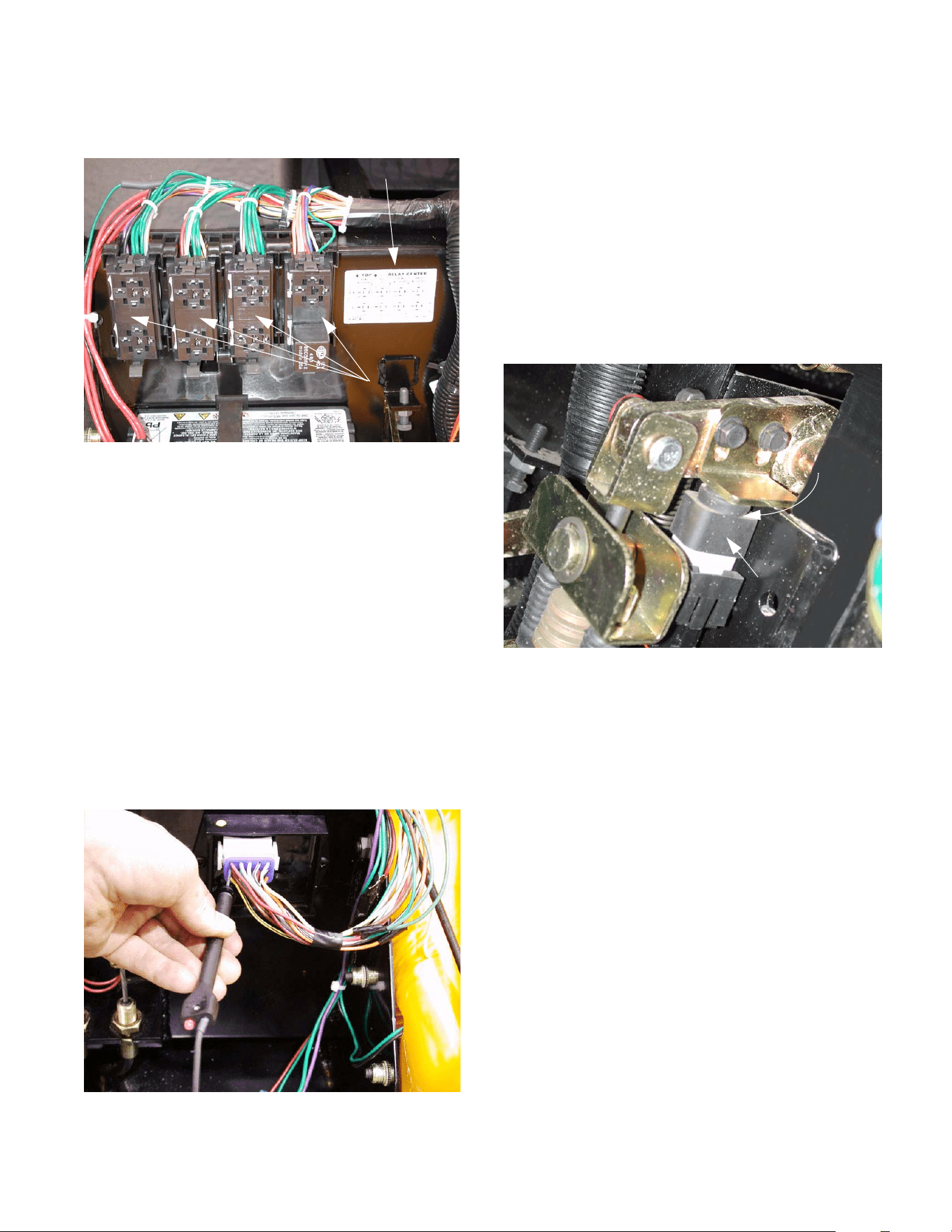
6.3. If the fuse is OK, check the relay.
See Figure 6.3.
TIP: The relay that controls power to the ESM also
controls power to the fuel shut-off solenoid. With the
relay uncovered, a technician should be able to hear
and feel the relay “click” when the key switch is turned
on. This click will confirm that the relay is getting
power. If the relay is successfully energizing the circuit
that contains the ESM, a report click should be heard
from the fuel shut-off solenoid. If the relay clicks but
the fuel shut-off solenoid does not, the relay may be
bad. Other possibilities include a fault in the wiring har-
ness downstream of the relay, or a defective fuel shut-
off solenoid.
6.4. If power is present coming from the relay, check
for power at the ESM. If there is no power to the
ESM, but there is power at the relay, a fault
exists in the wiring harness. See Figure 6.4.
Figure 6.3
Key to relay
center
removed
with covers
Relay center
Figure 6.4
Back-probing the harness
at the ESM connection
NOTE: Use this basic technique when checking
any in-puts or out-puts of the ESM. If power is
not found at the device that is connected to the
ESM, check for power where the wire in ques-
tion reaches the ESM. If the two do not corre-
spond, a the problem lies between them, in the
harness.
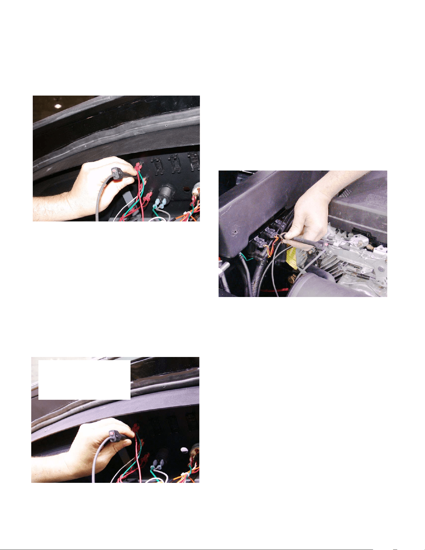
6.5. If it is established that the ESM has power, but
the gear selector does not respond to the but-
tons on the dashboard, check the brake switch.
See Figure 6.5.
NOTE: If the ESM does not know that the brake
pedal is pressed down, the gear selector sys-
tem will not operate. The brake switch must be
properly adjusted as described in the “Brake
Adjustment” section of this manual.
NOTE: The red wires that feed power to the
gear selector buttons get their power from
the brake switch.
NOTE: There are two pair of male spade con-
nectors on the back of the brake switch. Two of
them lead to a set of contacts that are normally
open (plunger up). The other two lead to a set of
contacts that are normally closed (plunger up).
The wires should be connected to the termi-
nals that lead to the normally closed con-
tacts. they can be identified by “NC” stamped
on the male spade terminal.
NOTE: There are two red wires that connect to
the brake switch. One is “hot” whenever the key
switch is turned on. The second red wire is con-
nected to the first (becoming hot) when the
brake pedal is depressed.
Figure 6.5
(normally open)
Brake switch
Plunger
down:
contacts
closed
4 X 2 Gear Selector
30
6.6. After power passes through the brake switch, it
reaches the gear selector button on the dash-
board. If power reaches these buttons, the
brake switch contacts are closed.
See Figure 6.6.
6.7. If the gear selector only works properly only
in one direction, the shift signal may not be
reaching the ESM from the gear selector button
on the dashboard.
6.8. With the key switch on, check the red wire that
connects to the back of each gear selector but-
ton to insure that it is getting power.
6.9. Press each button and check for power at the
downstream spade terminal on the back of the
button to confirm that the contacts are closing,
and it is passing the shift signal back to the
ESM. See Figure 6.9.
6.10. The vacuum tests may identify a vacuum sole-
noid that is not working properly. Check the
power to the solenoids to confirm whether the
problem is in the solenoid itself or in the electri-
cal signal to the solenoid.
NOTE: The orange with white trace wire that
leads to each vacuum solenoid is “hot”
whenever the key switch is in the on position.
The ESM energizes the vacuum solenoids by
creating a ground path through the second wire.
6.11. Check the orange with white trace wire for power
at each vacuum solenoid with the key switch in
the on position. See Figure 6.11.
6.12. If there is no power, but the ESM has been con-
firmed to have power, check for power at the
ESM end of the wire. If power is present at the
ESM end of the wire, the problem lies in the har-
ness between the ESM and the vacuum sole-
noid. If power is absent, the ESM may be at
fault.
6.13. Check the second wire on each vacuum sole-
noid (yellow with black trace for forward sole-
noid, orange for reverse solenoid) for power
when the corresponding gear is selected.
Figure 6.6
Checking for power at
gear selector buttons
Figure 6.9
Key switch “ON”
“Forward” button depressed
Voltage present
Figure 6.11
Testing for power to
the solenoid
4 X 2 Gear Selector
31
6.14. If power is present at the second wire, that
means that a ground path has successfully been
created, and the vacuum solenoid should be
open. See Figure 6.14.
6.15. If power and vacuum are present at the vacuum
solenoid, but vacuum is not being passed to the
port that leads to the vacuum actuator, replace
the vacuum solenoid.
NOTE: The solenoid can be double-checked by
substitution before replacement.
6.16. If the F-N-R lights on the instrument flash when
any of the gear selector buttons are pushed,
even after manually returning the shift wedge to
neutral, check the neutral switch.
See Figure 6.16.
Figure 6.14
Vacuum test at the
solenoid should
correspond with the
results of the
electrical test
Figure 6.16
Red wire with
white trace:
voltage present
in neutral
6.17. The red wire with white trace wire will show
power when the roller on the neutral switch is in
the detent in the shift wedge.
DIFFERENTIAL LOCK
6.18. With the hood open to gain access the back side
of the differential lock button, some tests can be
made at the button. See Figure 6.18.
6.19. The green wire provides a ground for the
bulb in the button that lights when the differen-
tial lock is engaged. If the differential lock works
normally, but the button does not light-up when it
is engaged, check this connection for continuity
to ground.
6.20. The orange wire should be hot whenever the
key switch is turned on.
6.21. The yellow wire with white trace should be hot
with the key on and the differential lock
engaged. The small branch off of that wire pro-
vides current to light-up the button when the dif-
ferential lock is engaged.
Figure 6.18
Differential lock button
Power to lamp
in button and
to solenoid
Ground
(green)
Hot lead
(orange)
4 X 2 Gear Selector
32
6.22. The yellow wire from the button activates the dif-
ferential lock solenoid. The green wire from the
solenoid provides a constant ground. Check for
power and vacuum at the upper port when ener-
gized. See Figure 6.22.
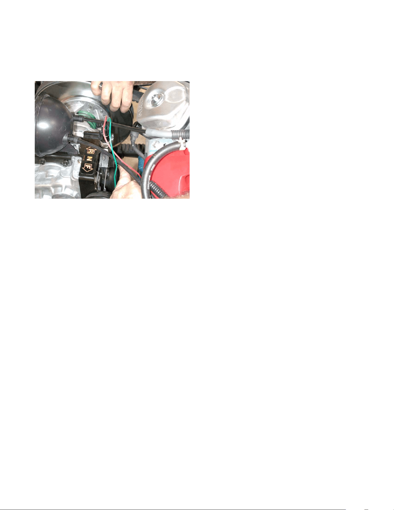
6.23. If the differential lock fails to engage, and the
vacuum and electrical systems appear to be
functioning correctly, isolate the mechanical por-
tion of the differential lock, and check it for free-
dom of movement and correct operation.
See Figure 6.23.
6.24. With the engine turned off, and the parking brake
released, remove the cotter pin and clevis pin
that secure the differential lock actuator arm to
the clevis on the vacuum actuator.
6.25. Engage and disengage-engage the differential
lock manually to test its function.
6.26. It will probably be necessary to rotate the input
shaft of the transmission in order to allow the dif-
ferential lock to engage. This can be done by
grasping the driven clutch and rotating it.
6.27. If the unit shows signs of tampering or previous
repair, check for correct alignment and adjust-
ment. See Figure 6.27.
6.28. The movement necessary to engage the differ-
ential lock should coincide with the action of the
vacuum actuator.
6.29. If the vacuum system, electrical system, and
adjustment are correct, there may be an internal
transmission problem.
6.30. If the gear selector fails to operate, and the vac-
uum and electrical systems appear to be func-
tioning correctly, isolate the mechanical portion
of the transmission, and check it for freedom of
movement and correct operation.
6.31. With the engine turned off, and the parking brake
released, move the manual over-ride lever to
shift gears. It should firmly engage forward and
reverse.
Figure 6.22
Green
ground wire
Yellow wire with white
trace: hot to energize
Figure 6.23
Vacuum actuator disconnected from
the differential lock actuator arm
Engage
Disengage
Figure 6.27
Splined shaft
Clamp bolt on arm
Adjustable
length
4 X 2 Gear Selector
33
6.32. It will probably be necessary to rotate the input
shaft of the transmission in order to allow the
gears to mesh. This can be done by grasping
the driven clutch and rotating it. See Figure 6.32.
6.33. If the manual over-ride does not work properly,
there may be an internal transmission problem.
Figure 6.32

4 X 2 Gear Selector
34

