GMR
™
XHD3 SERIES OPEN ARRAY RADAR
INSTALLATION INSTRUCTIONS
Important Safety Information
WARNING
See the Important Safety and Product Information guide in the product box for product warnings and other
important information.
Failure to install this device according to these instructions could result in personal injury, damage to the vessel
or device, or poor product performance.
The radar transmits electromagnetic energy. To avoid possible personal injury, damage to the vessel or device,
or poor product performance, ensure that the radar is installed according to the recommendations in these
instructions and that all personnel are clear of the path of the radar beam before transmitting. When properly
installed and operated, the use of this radar conforms to the requirements of ANSI/IEEE C95.1-1992 Standard
for Safety Levels with Respect to Human Exposure to Radio Frequency Electromagnetic Fields.
To avoid possible personal injury, do not look directly at the antenna at close range when the radar is
transmitting. Eyes are the most sensitive part of the body to electromagnetic energy.
When connecting the power cable, do not remove the in-line fuse holder. To prevent the possibility of injury or
product damage caused by fire or overheating, the appropriate fuse must be in place as indicated in the product
specifications. Connecting the power cable without the appropriate fuse in place voids the product warranty.
CAUTION
For the best possible performance and to avoid potential injury, damage to the device, or damage to your vessel,
installation by a qualified marine installer is recommended.
Opening the device may result in personal injury and/or damage to the device. This device contains no user-
serviceable parts, and should be opened only by a Garmin
®
authorized service technician. Any damage resulting
from opening the unit by anyone other than a Garmin authorized service technician will not be covered by the
Garmin warranty.
This device should be used only as a navigational aid. Using the device for any purpose requiring precise
measurement or direction, distance, location, or topography may result in personal injury or damage to the
vessel.
To avoid possible personal injury, always wear safety goggles, ear protection, and a dust mask when drilling,
cutting, or sanding.
NOTICE
When drilling or cutting, always check what is on the opposite side of the surface to avoid damaging the vessel.
TA-2012/1901
GUID-EB209D1E-8C29-450E-B406-01E29CD7AD9A v4May 2024

Tools Needed
• #2 Phillips screwdriver
• 5mm hex wrench
• Drill and 15.0 mm (
19
/
32
in.) drill bit
• 17mm (
21
/
32
in.) wrench and torque wrench
• A length of 3.31mm² (12AWG) copper wire to ground the radar housing (and voltage converter, if
applicable).
• Marine sealant
2
Mounting Considerations
When selecting a mounting location, observe these considerations.
•
WARNING
The radar must be mounted out of range of people, with the vertical beam width above head height. To avoid
exposure to harmful radio frequency (RF) levels, the radar must not be mounted closer to people than the
minimum safe distance value listed in the product specifications.
• The radar should be mounted high above the ship’s keel line with minimal blockage of the radar beam.
Obstructions may cause blind and shadow sectors or generate false echoes. The higher the installation
position, the farther the radar can detect targets.
• The radar should be mounted on a flat surface or a platform that is parallel to the vessel's water line and is
sturdy enough to support the radar's weight. The weight for each model and antenna is listed in the product
specifications.
• The radar must be mounted in a location where it can be connected to power, water ground, and network.
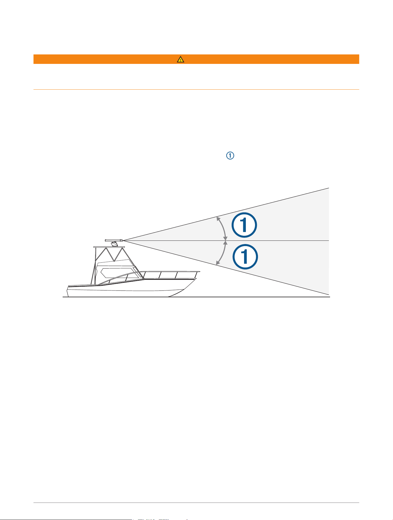
• The radar beam spreads vertically 11.5°above and 11.5°below the radar's radiating element. On vessels
with higher bow angles at cruise speed, the installation angle can be lowered to point the beam slightly
downward to the waterline while at rest. Shims can be used if necessary.
• The radar should be mounted away from heat sources, such as smoke stacks and lights.
• The radar should be mounted at a different level than horizontal spreaders and mast crosstrees.
• To avoid interference with a magnetic compass, the radar should not be mounted closer to a compass than
the compass-safe distance value listed in the product specifications.
• Other electronics and cables should be mounted more than 2m (6.5ft.) from the radar beam path.
• GPS antennas should be either above or below the radar beam path.
• The radar should be mounted at least 1m (40in.) from any transmitting equipment.
• The radar should be mounted at least 1m (40in.) away from cables carrying radio signals such as VHF
radios, cables, and antennas.
• The radar should be mounted at least 2m (6.5ft.) away from Single Side Band (SSB) radios.
3
Installation Procedures
Preparing the Radar Mounting Surface
Before you can mount the radar, you must choose a suitable mounting location (Mounting Considerations,
page3).
1 Secure the included mounting template to the surface at the mounting location, along the bow-stern axis, as
indicated on the template.
2 Drill the mounting holes using a 15mm (
19
/
32
in.) drill bit.
3 If you need to run the power and network cables through the mounting surface, select a location along
the center channel indicated on the template, drill a pass-through hole for the cables using a 32mm
(1
1
/
4
in.) drill bit, and route the cables through the surface (optional) (Wiring and Connection Considerations,
page6).
4 Remove the mounting template from the surface.
Mounting the Radar
Before you can mount the radar, you must select a mounting location (Mounting Considerations, page3) and
prepare the mounting surface(Preparing the Radar Mounting Surface, page4).
1 Place the radar onto the mounting surface, aligning the holes on the base of the radar with the holes you
drilled when preparing the mounting surface.
2 Apply the included primer (Petrolatum Primer) to half the length of each threaded rod.
3 Insert the primed end of each threaded rod through the mounting surface and into the radar base, and
tighten them using a 6mm hex wrench.
To avoid damaging the pedestal, you should stop tightening the threaded rods when they no longer turn
easily.
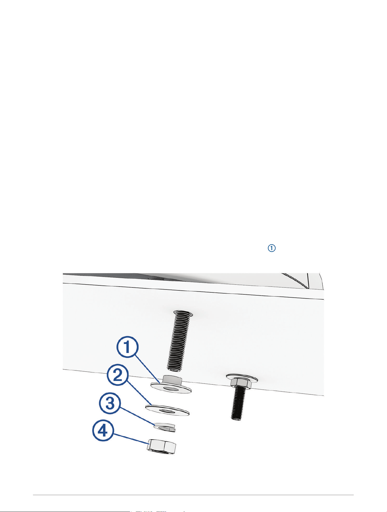
4 From under the mounting surface, place the included plastic shoulder washers over the threaded rods
and into the holes.
4
5 Place the flat washers , lock washers , and hex nuts on the threaded rods.
6 Tighten the hex nuts to a torque of 14.7N-m (11lbf-ft.) to securely fasten the radar to the surface without
damaging the radar or the mounting hardware.
Installing the Antenna
Before you can install the antenna on the pedestal, you must securely mount the pedestal (Mounting the Radar,
page4).
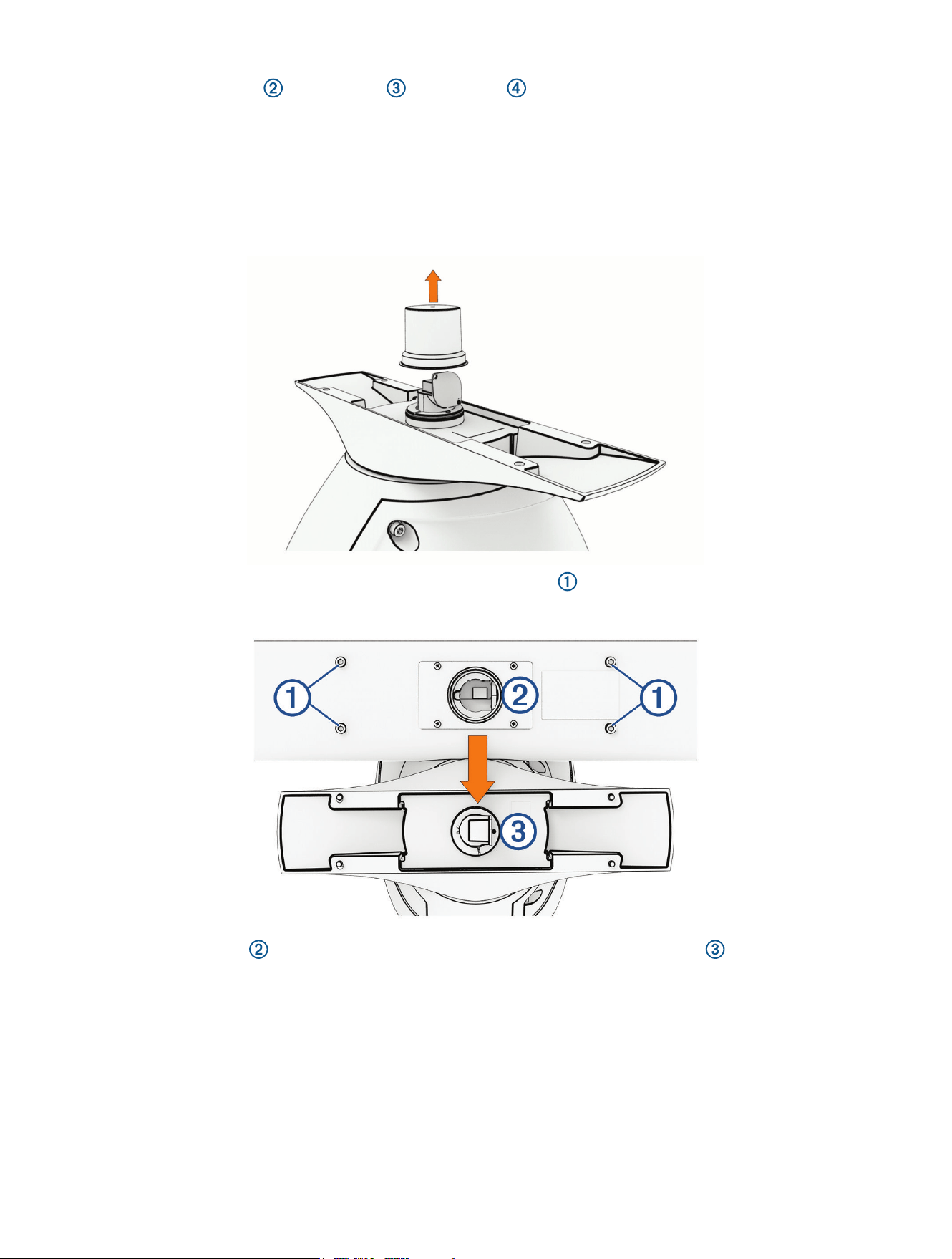
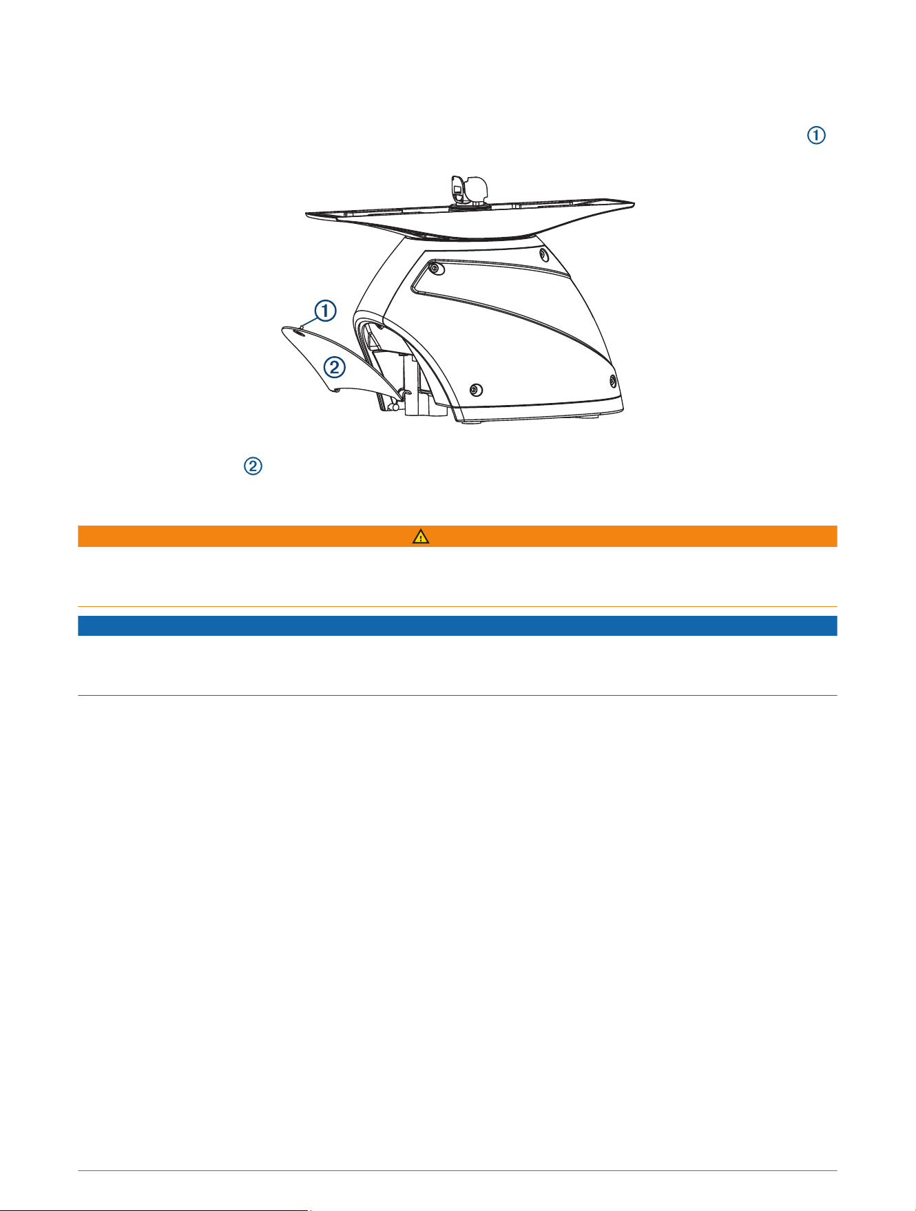
1 Remove the protective cover from the waveguide on the top of the pedestal.
2 Remove the mounting hardware from the bottom of the antenna .
These screws and washers are used to secure the antenna to the pedestal.
3 Align the waveguide on the pedestal with the socket on the bottom of the antenna , and slide the
antenna onto the pedestal.
5
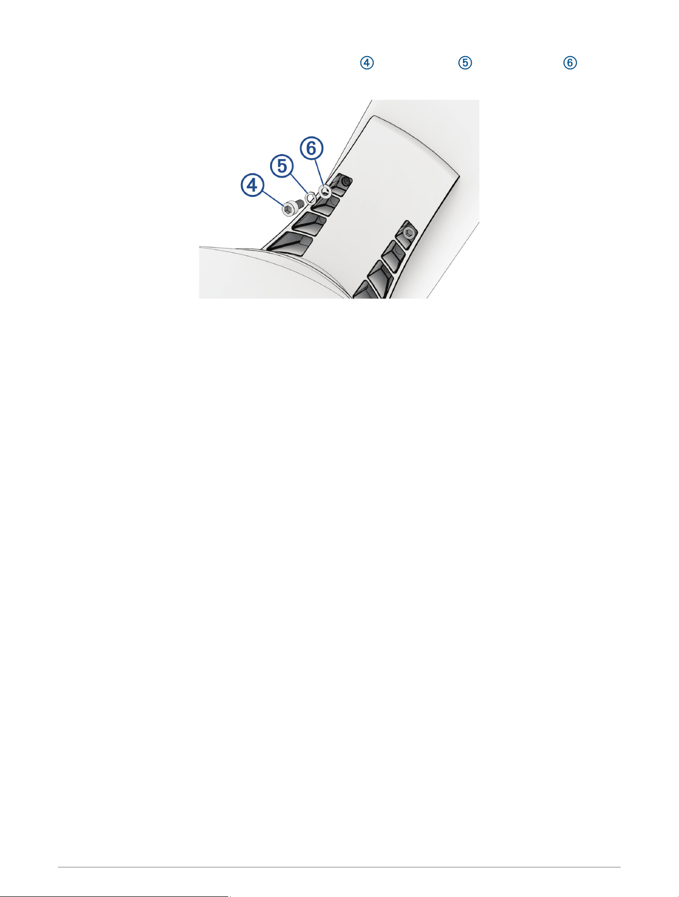
4 Secure the antenna to the pedestal using the hex screws , spring washers , and flat washers you
removed from the antenna.
5 Using a torque wrench, tighten the hex screws to 0.81kgf-m (70lbf-in or 5.83lbf-ft) to fasten the antenna to
the pedestal without damaging the antenna or the mounting hardware.
Wiring and Connection Considerations
It may be necessary to drill a hole up to 32mm (1
1
/
4
in.) in diameter for routing the power, network, or
grounding cables.
You must apply marine sealant to the hole after the cables are in place to ensure a waterproof seal.
If you must make the routing hole in a visible location, 32mm (1
1
/
4
in.) decorative cable grommets can be
purchased from your local Garmin dealer, or you can go to buy.garmin.com (optional).
• If needed, you can trim the grommet to enable you to route multiple cables through the same hole.
• The optional grommet does NOT provide a waterproof seal. You must apply marine sealant to the grommet
after the cables are in place to ensure a waterproof seal.
When installing the cables, you should observe these considerations.
• The ground cable is not included, and must connect to a water ground location, not the negative terminal of
the battery (Grounding the Radar, page10).
• To ensure safety, appropriate tie-wraps, fasteners, and sealant should be used to secure the cable along the
route and through any bulkheads or the deck.
• You should not run cables near moving objects and high-heat sources, or through doorways and bilges.
• To avoid interference with other equipment, you should not run network and power cables parallel to other
cables, such as radio antenna lines or power cables. If this is not possible, the cables should be shielded with
metal conduit or a form of EMI shielding.
• You should install the power cable as close to the battery source as possible.
◦ If it is necessary to extend the power cable, you must use the appropriate wire gauge (Power Cable
Extensions, page10).
◦ Incorrectly extended runs of cable may cause the radar to malfunction due to insufficient power
transmission.
6
Opening the Access Panel
To gain access to the power and network connectors, you must open the access panel on the back of the radar.
1 Using a flat screwdriver, loosen the captive screw that secures the access panel to the pedestal housing .
2 Lift the access panel up and away from the pedestal housing.
Connecting to Power Through the Voltage Converter
WARNING
When connecting the power cable, do not remove the in-line fuse holder. To prevent the possibility of injury or
product damage caused by fire or overheating, the appropriate fuse must be in place as indicated in the product
specifications. Connecting the power cable without the appropriate fuse in place voids the product warranty.
NOTICE
Do not reuse any voltage converters from previous Garmin radar models, or third party voltage converters. Using
any converter other than one included with the radar, or the correct converter purchased from Garmin or from
your local Garmin dealer may damage the radar or prevent it from turning on.
If your model is not packaged with a voltage converter, you can connect the power cable directly to the boat
battery (Connecting Directly to Power, page9).
When installing the voltage converter, observe these considerations.
• The voltage converter requires an input voltage of 10 to 32Vdc.
• You should install the voltage converter as close as possible to the power source.
• Connecting the power cable for the voltage converter directly to the battery is recommended. If it is
necessary to extend the cable, you must use the appropriate gauge of wire for the length of the extension
(Power Cable Extensions, page10).
7
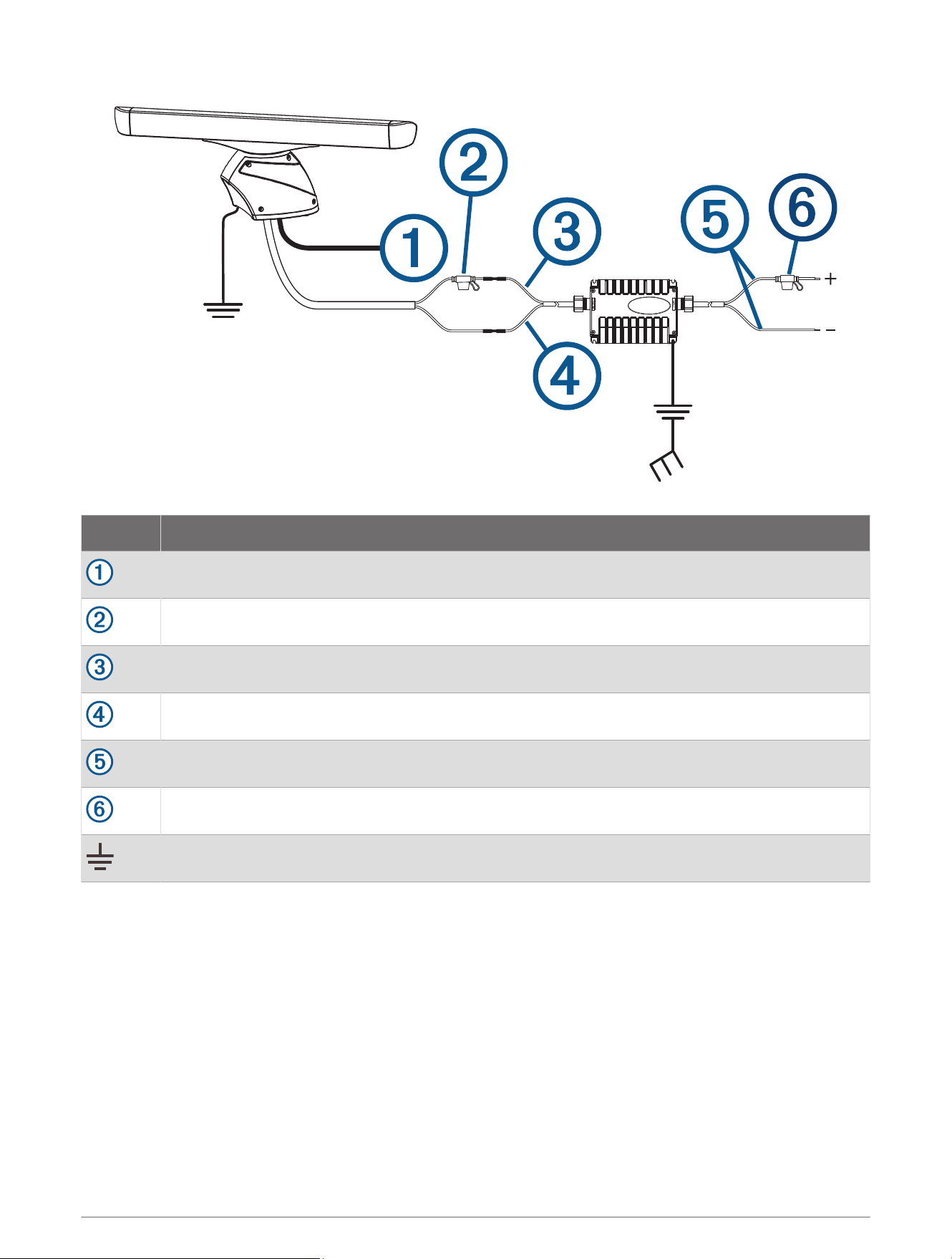
Item Description
Garmin BlueNet
™
network or Garmin Marine Network
15 Afuse holder
Red (+)
Black (-)
To the boat battery (10 to 32Vdc)
30A fuse holder
Water ground connection
1 Route the power cable to the radar and the voltage converter.
2 Use crimp connectors and heat-shrink tubing to connect the power cable to the voltage converter.
The radar power cable contains a 15 A fuse. You must not remove this fuse when connecting to the voltage
converter.
3 Connect the voltage converter to the boat battery through the included 30A fuse.
The 30A fuse between the voltage converter and battery is in addition to the 15 A fuse included in the radar
power cable. Both fuses must be in place for the radar to function properly.
4 Connect the power cable to the POWER port on the radar.
8
Connecting Directly to Power
WARNING
When connecting the power cable, do not remove the in-line fuse holder. To prevent the possibility of injury or
product damage caused by fire or overheating, the appropriate fuse must be in place as indicated in the product
specifications. Connecting the power cable without the appropriate fuse in place voids the product warranty.
NOTICE
If your radar was packaged with a voltage converter, you must install it with the voltage converter for the radar
to function properly (Connecting to Power Through the Voltage Converter, page7).
NOTE: Although some radar models do not require and are not packaged with a voltage converter, you can
purchase one from your local Garmin dealer or you can go to buy.garmin.com. Using a voltage converter
with these models allows them to withstand stronger winds. Check the Specifications section for the radar's
maximum wind load (Specifications, page13).
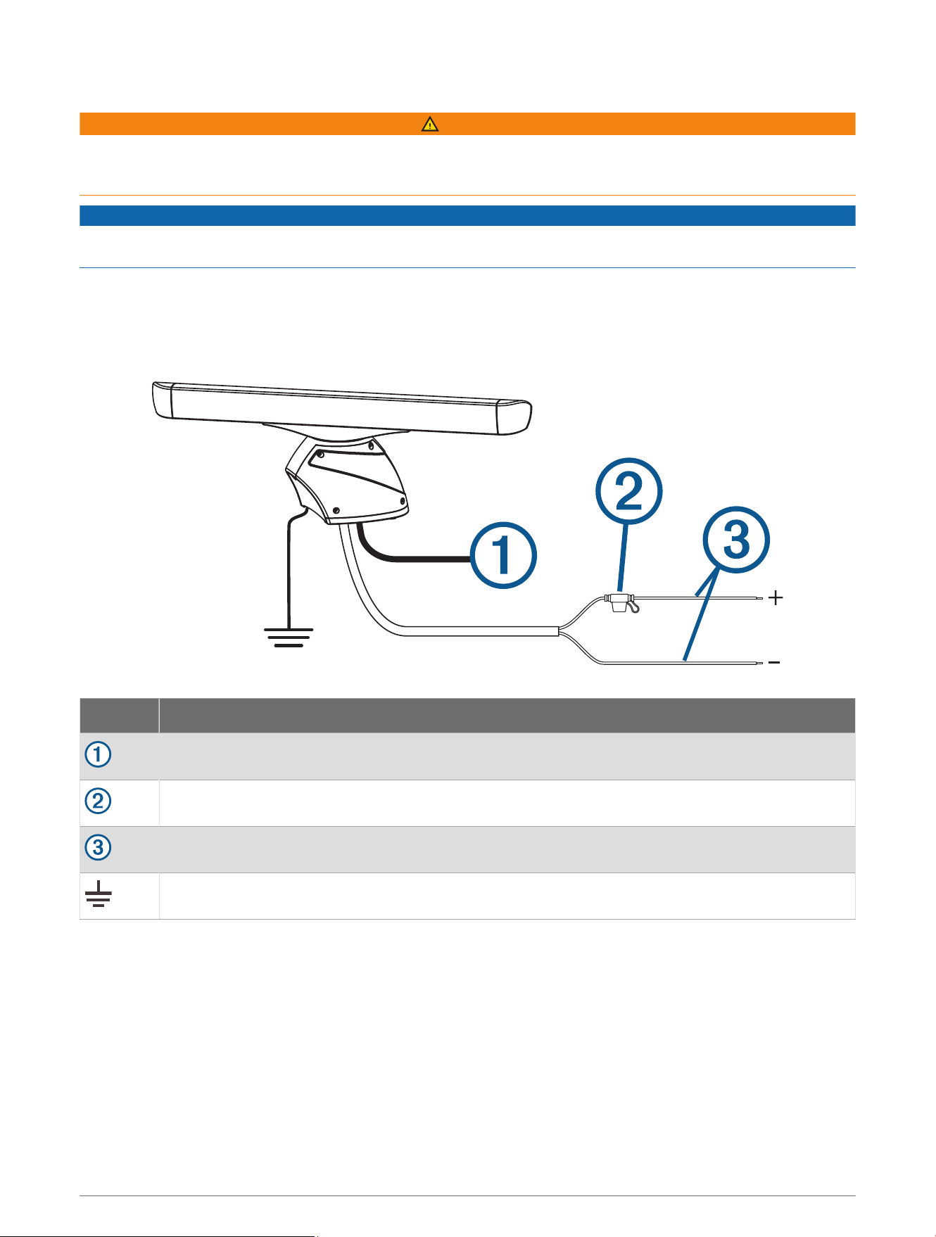
Item Description
Garmin BlueNet network or Garmin Marine Network
15 A fuse holder
To the boat battery (11 to 32Vdc)
Water ground connection
1 Route the power cable to the radar and boat battery.
2 Connect the power cable to the boat battery.
3 Connect the power cable to the POWER port on the radar.
9

Power Cable Extensions
Connecting the power cable directly to the battery is recommended. If it is necessary to extend the cable, the
appropriate gauge of wire must be used for the length of the extension.
You must use crimp connectors and heat-shrink to create a water-resistant connection.
Distance Wire Gauge
3m (9ft.10in.) 3.31mm² (12AWG)
5m (16ft.4in.) 5.26mm² (10AWG)
6.5m (21ft.3in.) 6.63mm² (9AWG)
8m (26ft.2in.) 8.36mm² (8AWG)
Grounding the Radar
The radar (and voltage converter, if applicable) must be connected to the appropriate type of ground using a
3.31mm² (12AWG) copper wire (not included).
1 Route a 3.31mm² (12AWG) copper wire to a water ground location and to the radar pedestal.
2 Connect the wire to the ground connector on the pedestal ( ) using the pre-installed crimp connector.
3 Coat the ground screw and crimp connector with marine sealant.
4 Connect the other end of the wire to the water ground location on the boat, and coat the connection with
marine sealant.
5 Select an option:
• If your radar was not packaged with a voltage converter, no further grounding is necessary.
• If your radar was packaged with a voltage converter, proceed to step 6.
6 Route a different 3.31mm² (12AWG) copper wire to water ground location and to the voltage converter.
7 Loosen a screw on one corner of the voltage converter and secure the copper wire to the screw.
8 Coat the screw and wire on the voltage converter with marine sealant.
9 Connect the other end of the wire to the RF ground location on the boat, and coat the connection with marine
sealant.
Networking Considerations
This device uses Garmin BlueNet networking technology, and is compatible with both Garmin BlueNet devices
and Garmin Marine Network devices. For more information about Garmin BlueNet technology, including best
practices for constructing a network including both Garmin BlueNet devices and Garmin Marine Network
devices, go to garmin.com/manuals/BlueNet.
Before connecting this device to the network, observe the following considerations:
• If your boat is equipped with a Garmin BlueNet chartplotter, you should connect the GMR xHD3 device to an
open network port on the Garmin BlueNet chartplotter or the Garmin BlueNet 20 switch, using the included
Garmin BlueNet cable.
• If your boat is equipped with a Garmin BlueNet chartplotter and uses a Garmin BlueNet 30 gateway to
connect Garmin Marine Network devices, you should connect the GMR xHD3 device to the Garmin BlueNet
side of your network, if possible, for the best performance and to best support future updates.
• If your boat is equipped with only Garmin Marine Network devices, you must use the Garmin Marine Network
adapter cable to connect the GMR xHD3 device to your network. If a Garmin Marine Network adapter cable
is not supplied in the product box, you can purchase one from your local Garmin dealer (part number
010-12531-01) or online at garmin.com/accessories/GMNAdapterCable.
10

Connecting to a Garmin BlueNet Network
1 Route the Garmin BlueNet cable to the GMR xHD3 device and to your Garmin BlueNet chartplotter or Garmin
BlueNet 20 switch.
2 Connect the Garmin BlueNet cable to the network port on the GMR xHD3 device.
3 Connect the other end of the Garmin BlueNet cable to any open network port on your Garmin BlueNet
chartplotter or the Garmin BlueNet 20 switch.
4 Tighten the locking rings on the connectors.
Connecting to a Garmin Marine Network
1 Route the Garmin BlueNet cable to the GMR xHD3 device and to your Garmin Marine Network chartplotter or
GMS
™
10 port expander.
2 Connect the Garmin BlueNet cable to the network port on the GMR xHD3 device.
3 Connect the other end of the Garmin BlueNet cable to the Garmin Marine Network adapter cable.
4 Connect the Garmin Marine Network adapter cable to an open network port on your Garmin Marine Network
chartplotter or the GMS 10 port expander.
5 Tighten the locking rings on the connectors.
Radar Operation
All functions of this radar are controlled with your Garmin chartplotter. See the Radar section of your
chartplotter's owner's manual for operating instructions. To download the latest manual, go to garmin.com
/manuals.
If you have more than one radar on your boat, you must be viewing the radar screen for the radar you want to
configure.
Software Update
You must update the Garmin chartplotter software when you install this device. For instructions on updating the
software, see your chartplotter owner's manual at support.garmin.com.
Specifying the Antenna Size
Before you can use the radar on your system, you must specify the antenna size.
1 Turn on the radar and all devices connected to the Garmin BlueNet network or the Garmin Marine Network.
An antenna-selection prompt appears on the connected chartplotters.
NOTE: If the entire system is being turned on for the first time, the antenna-selection screen is part of the
initial setup process.
2 Select the installed antenna size for each open-array radar installed on the boat.
TIP: If you need to specify a different antenna size, while viewing the radar screen for the radar you want to
change, select Options > Radar Setup > Installation > Antenna Configuration > Antenna Size, and select the
antenna size.
Measuring and Setting the Front-of-Boat Offset
The front-of-boat offset compensates for the physical orientation of the radar scanner on a boat, if the radar
scanner does not align with the bow-stern axis. The front-of-boat offset setting configured for use in one radar
mode is applied to every other radar mode and to the radar overlay.
1 Using a magnetic compass, take an optical bearing of a stationary target located within viewable range.
2 Measure the target bearing on the radar.
3 If the bearing deviation is more than +/- 1 degree, set the front-of-boat offset.
4 From a radar screen, select Options > Radar Setup > Installation > Front of Boat.
5 Select Up or Down to adjust the offset.
11

Setting a Custom Park Position
By default, the antenna is stopped perpendicular to the pedestal when it is not spinning. You can adjust this
position.
1 From the radar screen, select Options > Radar Setup > Installation > Antenna Configuration > Park Position.
2 Use the slider bar to adjust the position of the antenna when stopped, and select Back.
Installation Troubleshooting
Symptom Possible Causes
The radar does not turn
on. The status LED is not
on.
• The power cable may not be connected correctly to the device or to the battery.
Check all connections.
• The inline fuse may have blown. Check the fuse and replace it if necessary.
• The wire gauge used to extend the power cable may be too small for the
length of the extension. Check the table provided in the Power Cable Extensions
section of these instructions to make sure the correct wire gauge is used (Power
Cable Extensions, page10).
The radar is not available
on the Garmin device
or on devices connected
to the Garmin BlueNet
network or the Garmin
Marine Network.
• The radar may not be powering on. Check the status LED.
• The device software may not be up-to-date. Update the software on the device
or on the Garmin BlueNet network or the Garmin Marine Network.
• The network cable may not be connected correctly to the device or to the
Garmin BlueNet network or theGarmin Marine Network. Check all connections.
• If a field-installable network connector was used, it may have been installed
improperly. Check the connector.
The status LED is located on the product label, and can help troubleshoot installation problems.
Status LED Color and Activity Radar Status
Solid red
The radar is getting ready for use. The LED should be solid red briefly and
change to flashing green.
Flashing green The radar is operating properly.
Flashing orange The radar software is being updated.
Flashing red
The radar has encountered an error. Contact Garmin product support for assis
tance.
Contacting Garmin Support
• Go to support.garmin.com for help and information, such as product manuals, frequently asked questions,
videos, and customer support.
• In the USA, call 913-397-8200 or 1-800-800-1020.
• In the UK, call 0808 238 0000.
• In Europe, call +44 (0) 870 850 1241.
12

Specifications
Specification Measurement
Pedestal weight
GMR 430 xHD3:24.1kg (53.1lb.)
GMR 1230 xHD3:24.2kg (53.4lb.
GMR 2530 xHD3:24.9kg (54.9lb.)
Antenna weight
4ft. antenna: 5.5kg (12.2lb.)
6ft. antenna: 7.7kg (16.9lb.)
Power cable length 15m (49ft. 3in.)
Network cable length 15m (49ft. 3in.)
RF transmit frequency 9410MHz nominal
Antenna rotation speed 24rpm and 48rpm
Maximum wind load
GMR 430 xHD3: 80kn
1
GMR 1230/2530 xHD3: 100kn
Operating temperature range From -25 to 55°C (from 5 to 131°F)
Humidity 95% at 35°C (95°F)
Water rating IEC 60529 IPX6
2
Max. range
GMR 430 xHD3: 72nm
GMR 1230/2530 xHD3: 96nm
Min. range 20m (66ft.)
Peak transmit power
GMR 430 xHD3: 4KW
GMR 1230 xHD3: 12KW
GMR 2530 xHD3: 25KW
Beam width
4ft. antenna: 1.8 degrees horizontal, 23 degrees vertical
6ft. antenna: 1.1 degrees horizontal, 23 degrees vertical
Bearing accuracy 0.25degrees
Input voltage
GMR 430 xHD3: From 11 to 32Vdc
GMR 1230/2530 xHD3: From 10 to 32Vdc
Fuse
Without voltage converter: 15 A, blade-type
With voltage converter (if applicable): 30A, blade-type
Power consumption, standby 18W
Power consumption, transmitting
GMR 430 xHD3: 55W
GMR 1230/2530 xHD3: 70W
Compass-safe distance
Standard compass: 90cm (35
7
/
16
in.)
Standby steering and emergency compasses: 80cm (31
1
/
2
in.)
1
If a 430 xHD3 is installed using an optional voltage converter, it is capable of withstanding winds of up to 100kn.
2
The device withstands incidental exposure to water of up to 1m for up to 30min, and is protected against powerful jets of water. For more information, go to
www.garmin.com/waterrating.
13

Minimum Safe Operating Distances
When it is transmitting, the radar should be located in a position on the vessel that is at least this far
from people. IEC60936-1, clause3-27.1, specifies the maximum distances from the antenna at which radio
frequency (RF) levels can be expected.
These minimum safe distances apply for a transmitting radar with a rotating antenna, and are much larger
when the antenna is not rotating. If rotation of the antenna is obstructed for any reason, the transmitter will
automatically turn off.
Model 100W/m² 50W/m² 10W/m²
GMR 434 xHD3 0.09m (3.54in.) 0.13m (5.11in.) 0.28m (11.02in.)
GMR 436 xHD3 0.09m (3.54in.) 0.13m (5.11in.) 0.30m (11.81in.)
GMR 1234 xHD3 0.15m (5.91in.) 0.22m (8.66in.) 0.49m (19.29in.)
GMR 1236 xHD3 0.16m (6.30in.) 0.23m (9.06in.) 0.51m (20.08in.)
GMR 2534 xHD3 0.16m (6.30in.) 0.22m (8.66in.) 0.50m (19.69in.)
GMR 2536 xHD3 0.17m (6.69in.) 0.23m (9.06in.) 0.52m (20.47in.)
Antenna Specifications
Specification Measurement
Type End-fed slotted waveguide
Horizontal beam width
4ft. antenna: 1.8 degrees
6ft. antenna: 1.1 degrees
Horizontal side lobes
-23dB within ±10 degrees of main
-30dB outside ±10 degrees of main
Vertical beam width 23º
Antenna gain
4ft. antenna: 27dB
6ft. antenna: 29dB
Polarization Horizontal
14
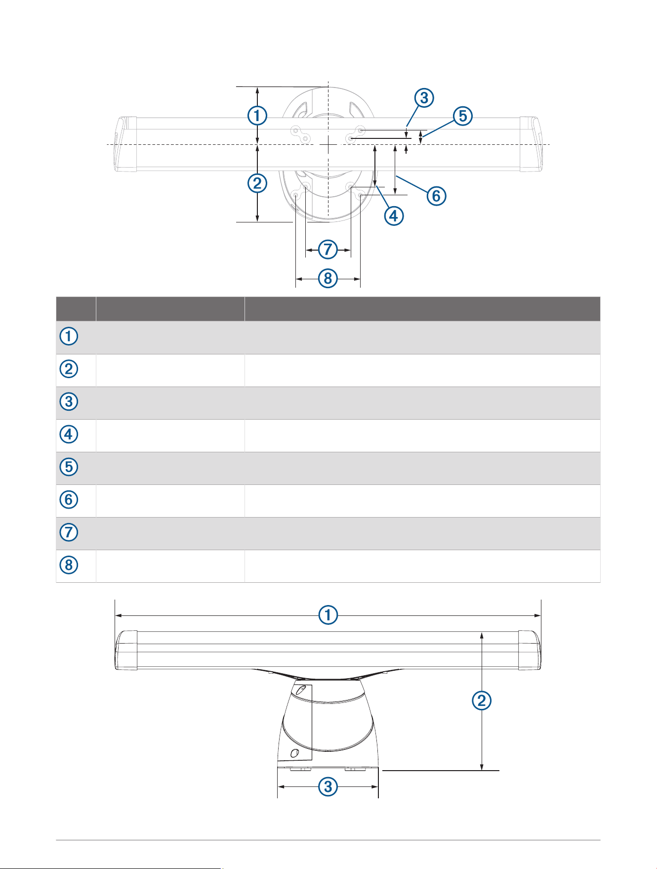
Dimensions
Item Measurement Description
181.8mm (7
3
/
16
in.) Center of rotation to the rear of the pedestal.
236.2mm (9
5
/
16
in.) Center of rotation to the front of the pedestal.
25mm (1in.) Center of rotation to the inner rear mounting holes.
125mm (4
15
/
16
in.) Center of rotation to the inner front mounting holes.
50mm (1
15
/
16
in.) Center of rotation to the outer rear mounting holes.
150mm (5
29
/
32
in.) Center of rotation to the outer front mounting holes.
140mm (5
1
/
2
in.)
200mm (7
7
/
8
in.)
15
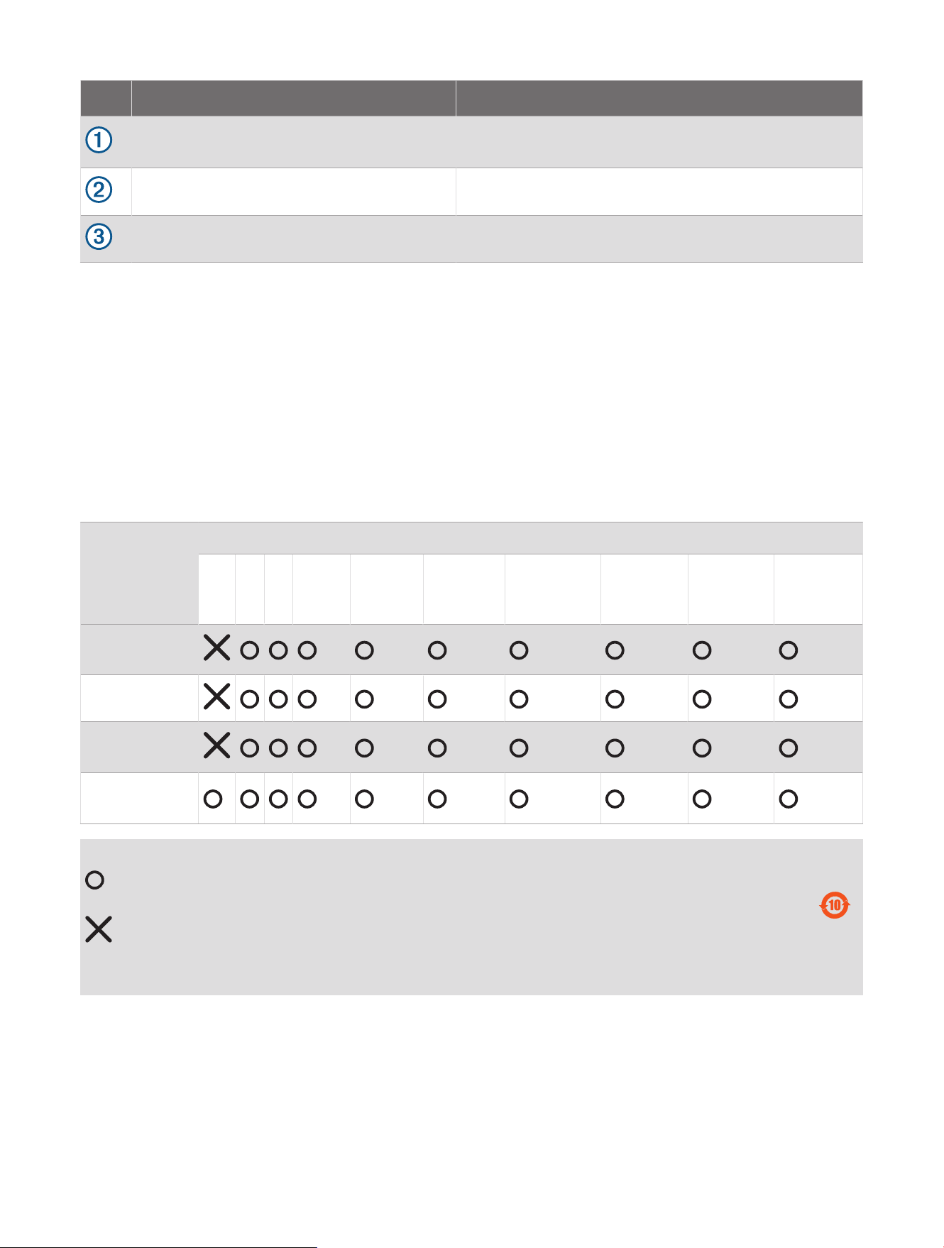
Item Measurement Description
4ft. models: 132.7cm (4ft. 4
1
/
4
in.)
6ft. models: 193.7cm (6ft. 4
1
/
4
in.)
Antenna length.
45.1cm (17
3
/
4
in.) Base of the pedestal to the top of the antenna.
31.8cm (12
1
/
2
in.) Width of the pedestal.
Open-Source Software License
To view the open-source software license(s) used in this product, go to developer.garmin.com/open-source
/linux/.
連絡地址
製造銷售:台灣國際航電股份有限公司
聯絡地址:新北市汐止區樟樹二路 68 號
電 話:(02)2642-8999
客服專線:(02)2642-9199
物質宣言
部件名称
有毒有害物质或元素
铅 汞 镉 六价铬 多溴联苯
多溴二苯
醚
邻苯二甲酸
二(2-乙基
己)酯
邻苯二甲
酸丁苄酯
邻苯二甲
酸二丁酯
邻苯二甲酸
二异丁酯
印刷电路板组
件
金属零件
电缆 电缆组件
连接器
塑料和橡胶零
件
本表格依据 SJ/T11364 的规定编制。
: 代表此种部件的所有均质材料中所含的该种有害物质均低于
(GB/T26572) 规定的限量
: 代表此种部件所用的均质材料中, 至少有一类材料其所含的有害物质高于
(GB/T26572) 规定的限量
* 该产品说明书应提供在环保使用期限和特殊标记的部分详细讲解产品的担保使用条件。
产品
© 2023 Garmin Ltd. or its subsidiaries
Garmin
®
and the Garmin logo are trademarks of Garmin Ltd. or its subsidiaries, registered in the USA and other countries. GMR
™
is a trademark of Garmin Ltd. or its
subsidiaries. These trademarks may not be used without the express permission of Garmin.
NMEA
®
, NMEA 2000
®
, and the NMEA 2000 logo are registered trademarks of the National Marine Electronics Association.
M/N: AB4560 / AA4560 / A04560
IC: 1792A-B4560 / 1792A-A4560 / 1792A-04560
雷達底座 / 雷達天線
© 2023 Garmin Ltd. or its subsidiaries
support.garmin.com