

USER MANUAL

Pg.
Pg. 2
TABLE OF CONTENTS
1. SAFETY INFORMATION 3
2. TOOL OVERVIEW 5
2.1. TOOL CONTROLS 5
2.2. KIT CONTENTS 6
2.3. ACTIVATING SENSORS 6
3. CONNECTING TO WIFI 7
4. TPMS 8
4.1. SELECTING A VEHICLE 8
4.2. SELECTING A TPMS FUNCTION 9
4.3. CHECK TPM 10
4.4. RESET 11
4.4.1. MANUAL RELEARN 11
4.4.2. OBDII RELEARN 12
4.5. PROGRAM 13
4.5.1. CREATE 14
4.5.2. COPY 14
4.5.3. COPY SET 15
4.5.4. CREATE SET 16
4.5.5. RETRIEVE ID 17
4.5.6. MANUAL ID 18
4.6. PLACARD 20
4.7. ID MATCH 22
4.8. TPM DTC 24
4.9. KEYFOB 25
4.10. TIRE TREAD 26
4.11. TRAILER TPMS 27
4.12. TIRE INSPECTION 28
4.13. REPORT 29
4.13.1. SETTING UP AN EMAIL ACCOUNT 29
4.13.2. SENDING AN EMAIL REPORT 30
4.14. SUPPORT 32
5. UPDATE 33
6. HISTORY 34
7. SECURE GATEWAY 35
8. HELP 36
9. SETTINGS 37
10. WARRANTY 38

Pg.
Pg. 3
1. SAFETY INFORMATION
Markings and Documentation
Equipment shall bear markings as specied below. Except for marking of internal parts, these markings shall be visible from the exterior, or
be visible after removing a cover or opening a door without the aid of a tool, if the cover or door is intended to be removed or opened by an
operator. Marking applying to the equipment as a whole shall not be put on parts which can be removed by an operator without the use of all
tool. There are no color requirements for symbols. Graphic symbols shall be explained in the documentation.
• Use of diagnostic equipment can cause electrical shock, re and explosion.
Use caution and proper procedures when connecting and disconnecting leads. Diagnostic equipment must be located 18” or more above oor
level. Avoid sparks and other sources of ignition.
Electrical shock, ames and explosion can cause serious injury.
• Improper use can cause hazardous conditions.
Unexpected electrical, thermal or mechanical occurrences can cause injury.
Read and follow all safety precautions accompanying the product. Wear safety goggles.
• Electromagnetic and electronically generated waves may interfere with pacemakers.
Individuals with pacemakers should never use this product.
Using this product with a pacemaker can result in serious injury or death.
• Internal battery presents a risk of re, explosion and electric shock.
Charge battery pack only with charger provided.
Do not operate at temperatures above 120°F (50°C). Do not store at temperatures above 140°F (60°C).
Do not discard used batteries; return them to a Snap-on repair center for recycling. Follow all safety messages
in the user manual.
Warning: This product can expose you to chemicals such as Diisononyl Phthalate (DINP), which is known to the State of California to cause
cancer and chemical such as Bisphenol A (BPA), which is known to the State of California to cause birth defect or other reproductive harm.
Fire or explosion or electric shock can cause injury.
Input Rating: DC5V, 1A
Operating temperature range: -10°C ~ 50°C
Storage Temperature range: -20°C ~ 60°C
Operating Humidity: 20 ~ 85 % RH. NON-CONDENSING
Storage Humidity: 5 ~ 95 % RH. NON-CONDENSING
IP54: Dust-Protected and protected against splashing water.

Pg.
Pg. 4
This device complies with Part 15 of the FCC Rules. Operation is subject to the following two conditions:
(1) This device may not cause harmful interference, and
(2) This device must accept any interference received, including interference that may cause undesired operation.
Federal Communication Commission Interference Statement
This equipment has been tested and found to comply with the limits for a Class B digital device, pursuant to Part 15 of the FCC Rules. These limits are
designed to provide reasonable protection against harmful interference in a residential installation.
This equipment generates, uses and can radiate radio frequency energy and, if not installed and used in accordance with the instructions, may cause
harmful interference to radio communications. However, there is no guarantee that interference will not occur in a particular installation. If this equipment
does cause harmful interference to radio or television reception, which can be determined by turning the equipment o and on, the user is encouraged to
try to correct the interference by one of the following measures:
. Reorient or relocate the receiving antenna.
. Increase the separation between the equipment and receiver.
. Connect the equipment into an outlet on a circuit dierent from that to which the receiver is connected.
. Consult the dealer or an experienced radio/TV technician for help.
FCC Caution: To assure continued compliance, any changes or modications not expressly approved by the party responsible for compliance could void the
user’s authority to operate this equipment. (Example - use only shielded interface cables when connecting to computer or peripheral devices).
FCC Radiation Exposure Statement
This equipment complies with FCC RF radiation exposure limits set forth for an uncontrolled environment. The exposure standard for wireless devices
employing a unit of measurement is known as the Specic Absorption Rate, or SAR. The SAR limit set by the FCC is 1.6W/kg.
The FCC has granted an Equipment Authorization for this device with all reported SAR levels evaluated as in compliance with the FCC RF exposure
guidelines. SAR information on this device is on le with the FCC and can be found under the Display Grant section of www.fcc.gov/oet/ea/fccid
This transmitter must not be co-located or operating in conjunction with any other antenna or transmitter.
IP
54
Pg.
Pg. 5
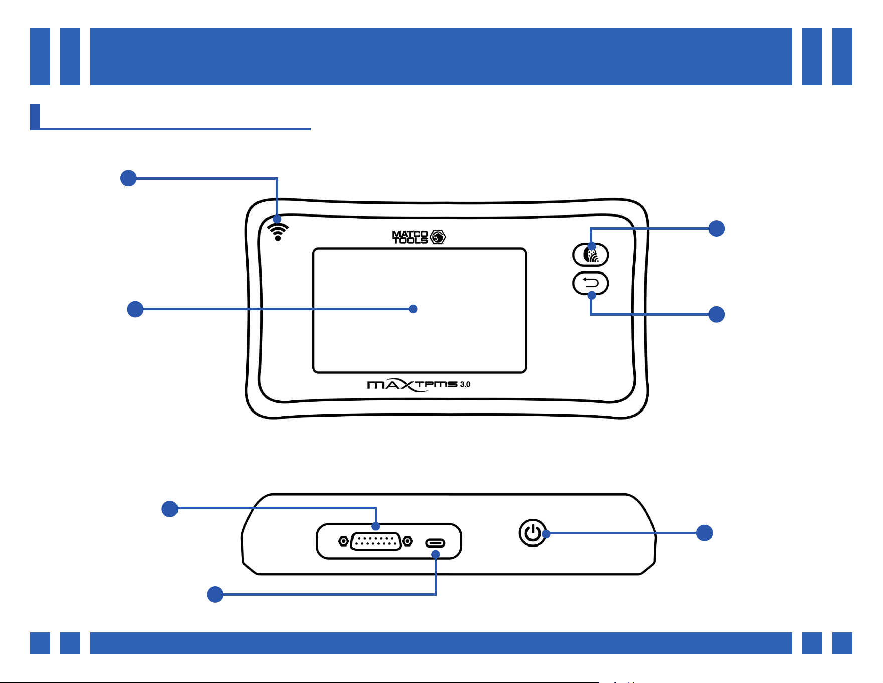
2. TOOL OVERVIEW
Top
Front
Antenna
Display
Trigger/Activate
Back/Cancel
OBDII Port
Charging Port (USB-C)
Power ON/OFF
2.1. TOOL CONTROLS

Pg.
Pg. 6
2.2. KIT CONTENTS
Carrying Case
T9530517A
MAXTPMS 3.0
MDMAX3.0
OBDII Cable
T5010090
Universal Charger
T5100024-67
USB-C Cable
T5010077
2.3. ACTIVATING SENSORS
When activating sensors, position the tool’s antenna on the sidewall of the tire,
near the valve.
Reading the sensor through the sidewall, as opposed to the rim will avoid any
potential interference.
Pg.
Pg. 7
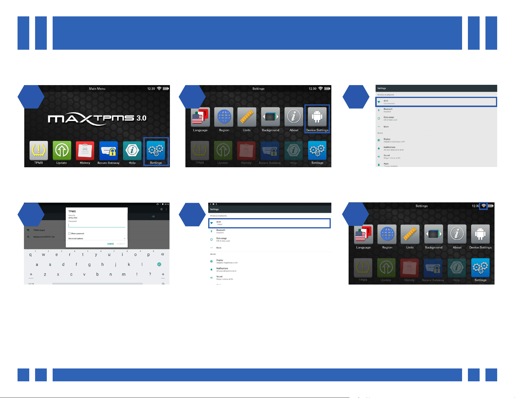
3. CONNECTING TO WIFI
Many of the functions on the tool require use of a WiFi connection including: Updating, emailing reports, contacting support, and
access to secure gateway vehicles.
1 2 31 2
1 24 5
From the main menu, select “Settings”. From the Settings menu, select “Device
Settings”.
The device settings will be displayed. Begin
by selecting the WiFi setting at the top of the
screen.
Select a preferred WiFi network, and enter the
password. Once nished, select “CONNECT”.
Once connected, the WiFi network name will be
displayed. To return to the tool settings, press
the back button on the front of tool.
26
Back in the tool settings, a WiFi icon will be
displayed at the top of the screen, indicating
the tool is now connected to WiFi.
Pg.
Pg. 8
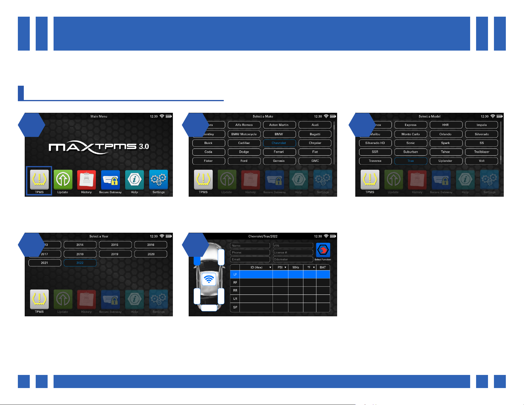
4. TPMS
4.1. SELECTING A VEHICLE
The TPMS screen contains all of the major functions of the tool. All TPMS related functions can be accessed after selecting a
vehicle Make, Model, and Year.
1 2 31 2
1 24 5
From the main menu, select “TPMS”. Select the vehicle’s Make. *Use one nger to
scroll up or down the list of vehicles.
Select the vehicle’s Model.
Last, select the vehicle’s Year. Once a vehicle has been selected, the main
vehicle screen will be displayed.

Pg.
Pg. 9
4.2. SELECTING A TPMS FUNCTION
Once on the main vehicle screen, a variety of functions can be accessed all from the same menu.
1 2 31 2
14
On the main vehicle screen, select a function
by pressing the icon on the top right corner.
A pop-up menu will be displayed with all of the
major TPMS functions. Tap a function to swap
to its display.
For example, if “Reset” is selected the
bottom portion of the screen will change to
that function. The car display and customer
information will still be displayed.
To swap to a dierent function, simply select
the icon at the top right once again.
Pg.
Pg. 10
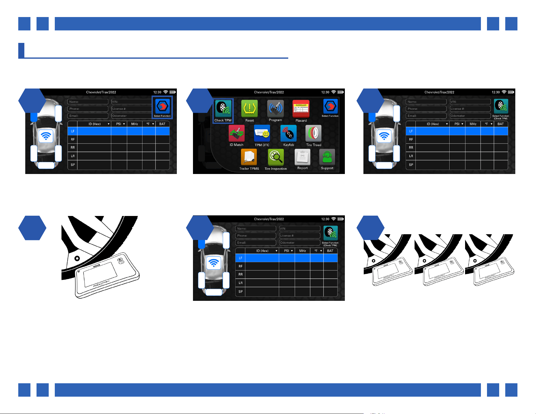
4.3. CHECK TPM
The Check TPM function is used to perform a quick check of all of the sensors in the vehicle.
1 2 31 2
14
Check TPM is the default function
selected on the main vehicle screen.
If a dierent function has been selected, tap the
select function icon at the top right, and select
“Check TPM”
Begin by selecting a tire from the main vehicle
screen.
Point the tool’s antenna at the sensor through
the tire sidewall and press the trigger button
on the front of the tool itself, or the on-screen
trigger icon.
25
The tool will display all of the sensor’s
information including ID, pressure, frequency,
temperature, and battery status.
6
Repeat the process for the remaining sensors.
ABCD1234 36.1 315 75 OK

Pg.
Pg. 11
4.4. RESET
For many Makes and Models, the vehicle must be put into a “learn” mode before the sensors can be relearned. The tool provides
instructions on how to perform these procedures. *Note: Refer to the tool’s built-in instructions for each specic procedure.
1 2 31 2
11
On the main vehicle screen, select a function
by pressing the icon on the top right corner.
From the function select menu, select “Reset”. The tool will display options for both Manual
and OBDII.
From the Reset menu, select “Manual”
4.4.1. MANUAL RELEARN
2 32
The tool will display the relearn instructions, as
well as a chart for all sensor information. Begin
by following the procedure to put the vehicle
into a “learn” mode”. Many times the vehicle’s
horn will honk indicating the vehicle is now in a
learn mode.
Once the vehicle is in a learn mode, begin by
scanning each sensor in the order listed in the
instructions. Once complete, the horn will honk
twice, indicating the procedure is complete.
Pg.
Pg. 12
1 2 31 2
14
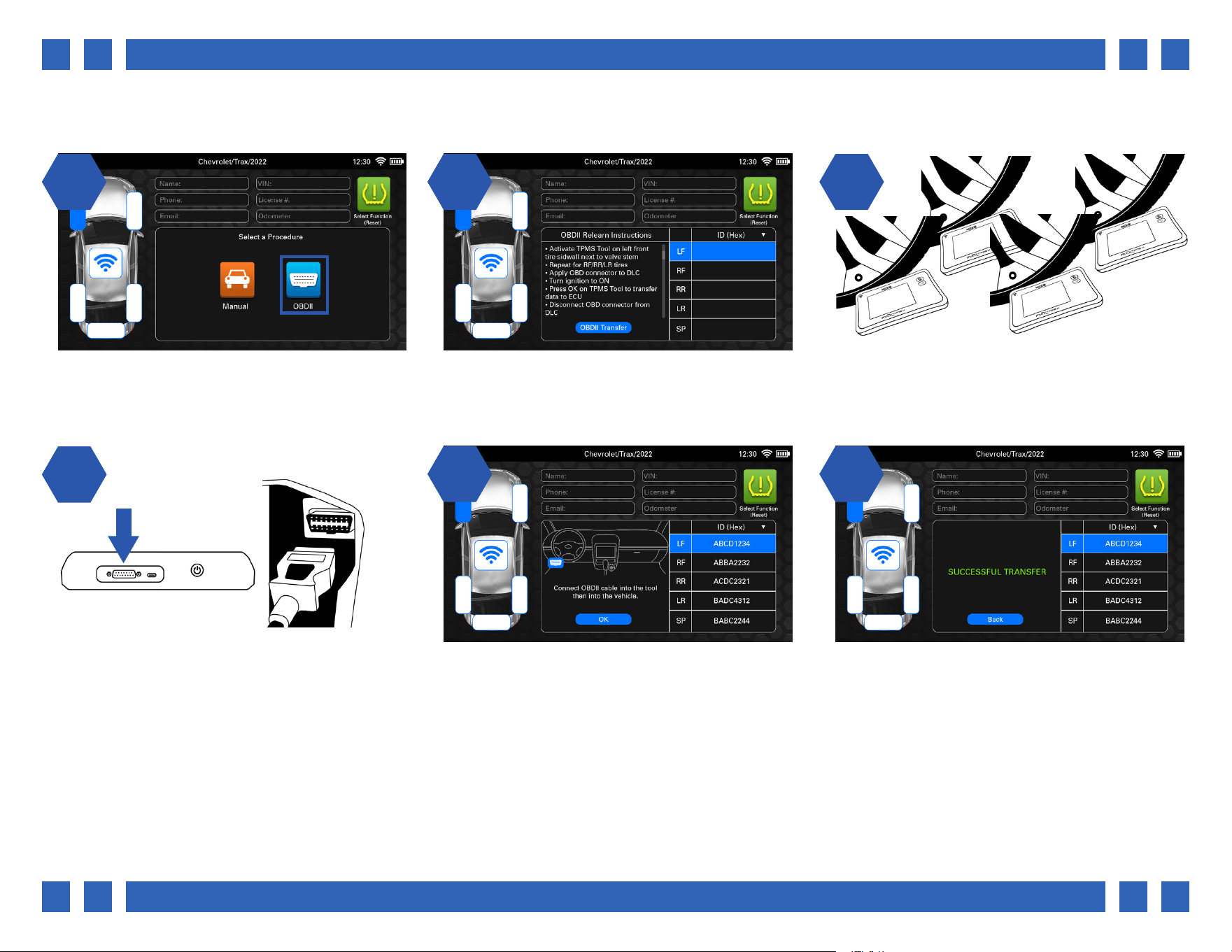
From the Reset menu, select “OBDII” The tool will display the relearn instructions, as
well as a chart for all sensor information.
Begin by scanning each sensor in the order
listed in the instructions.
Once all sensors have been scanned, plug the
OBDII cable into the top of the tool, and the
other end into the vehicle’s OBDII port. Select
“OBDII Transfer”.
25
If you are having trouble locating the OBDII
port, the tool will display the correct location.
Once ready, select “OK”.
6
After a few moments, the new sensor
information will be transferred to the ECU and
the tool will display “SUCCESSFUL TRANSFER”.
4.4.2. OBDII RELEARN
Pg.
Pg. 13
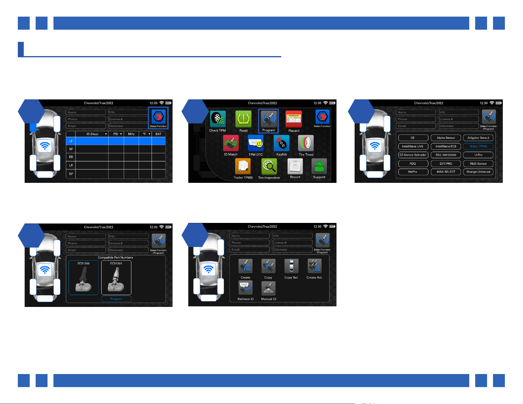
4.5. PROGRAM
The Program function is used to program a vast array of aftermarket sensors in a variety of dierent ways, as well view OEM
sensor and Service Kit information. All sensors include images and part numbers to help with identication. *Note: Not all
aftermarket sensor brands share the same functions. This section will provide examples of each available function.
1 2 31 2
14
On the main vehicle screen, select a function
by pressing the icon on the top right corner.
From the function select menu, select
“Program”.
The tool will display all of the aftermarket
sensor brands compatible for that vehicle, as
well as OE sensor information. Select a sensor
brand to begin.
The tool will then display each compatible
sensor model. Select a sensor, and then
“Program” to continue.
25
All of the available programming functions
for that sensor will be displayed. *Note: Not
all aftermarket sensor brands share the same
functions.
Pg.
Pg. 14
1 2 31 2
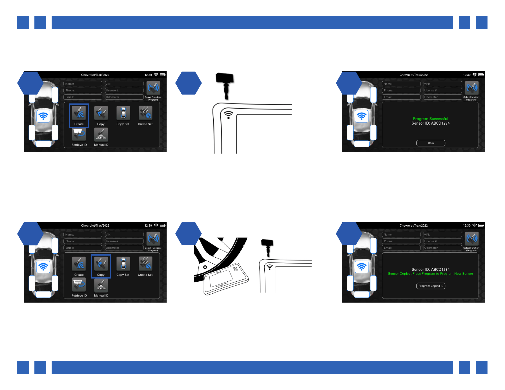
11
From the Program menu, select “Create” Place the new sensor above the tool’s antenna
and select “Program”.
After a few moments the new sensor ID will be
displayed and the tool will display “Program
Successful”.
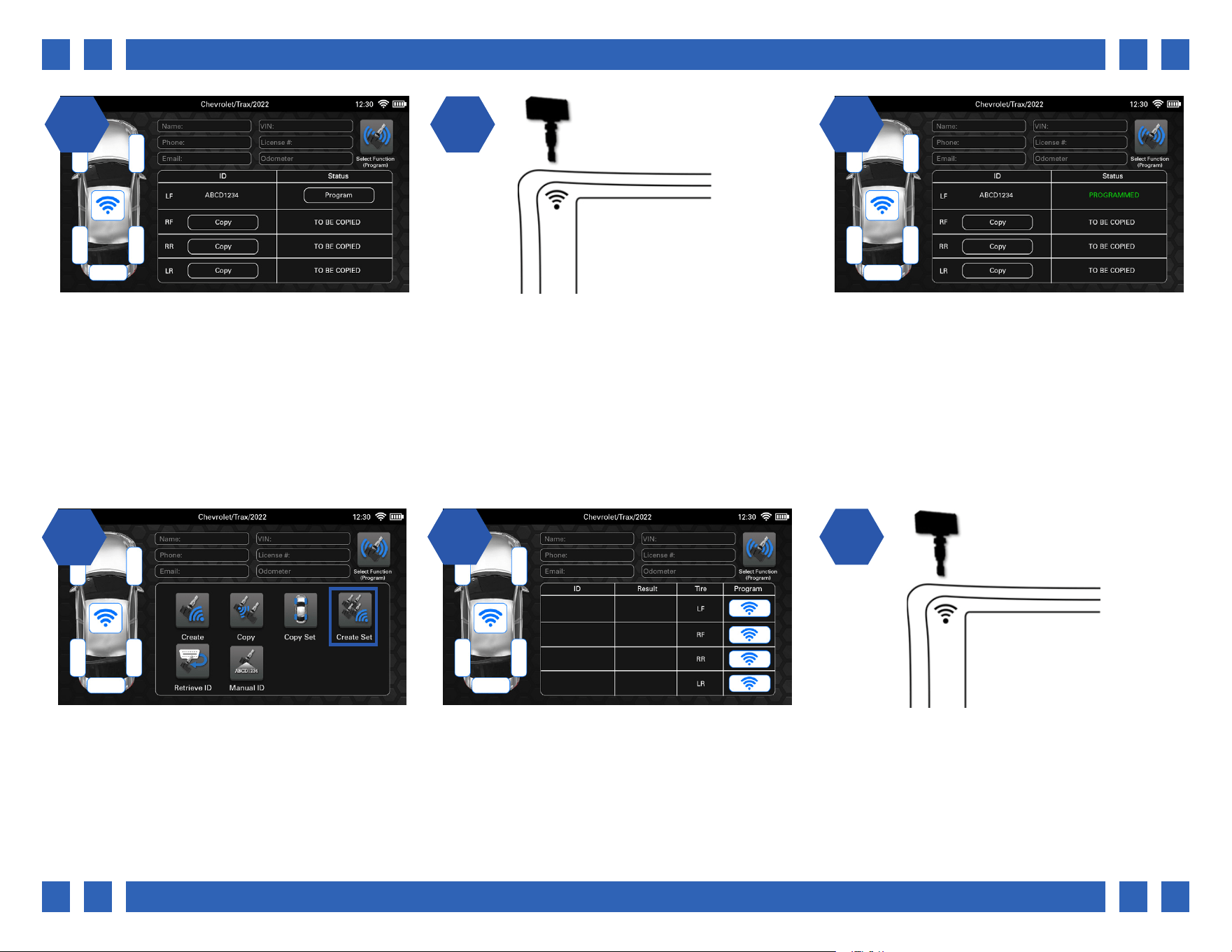
From the Program menu, select “Copy”
22
If the original sensor is still installed in the
wheel, point the tool’s antenna through the
tire sidewall and select “Copy”. If it has been
removed, place it above the tool’s antenna and
select “Copy”.
3
Once the ID has been copied, the tool will
display the original sensor’s ID.
4.5.1. CREATE
The Create function is used to program a brand new sensor ID to a blank aftermarket sensor.
4.5.2. COPY
The Copy function is used copy the ID from an existing sensor, and program it to a blank aftermarket sensor.
Pg.
Pg. 15
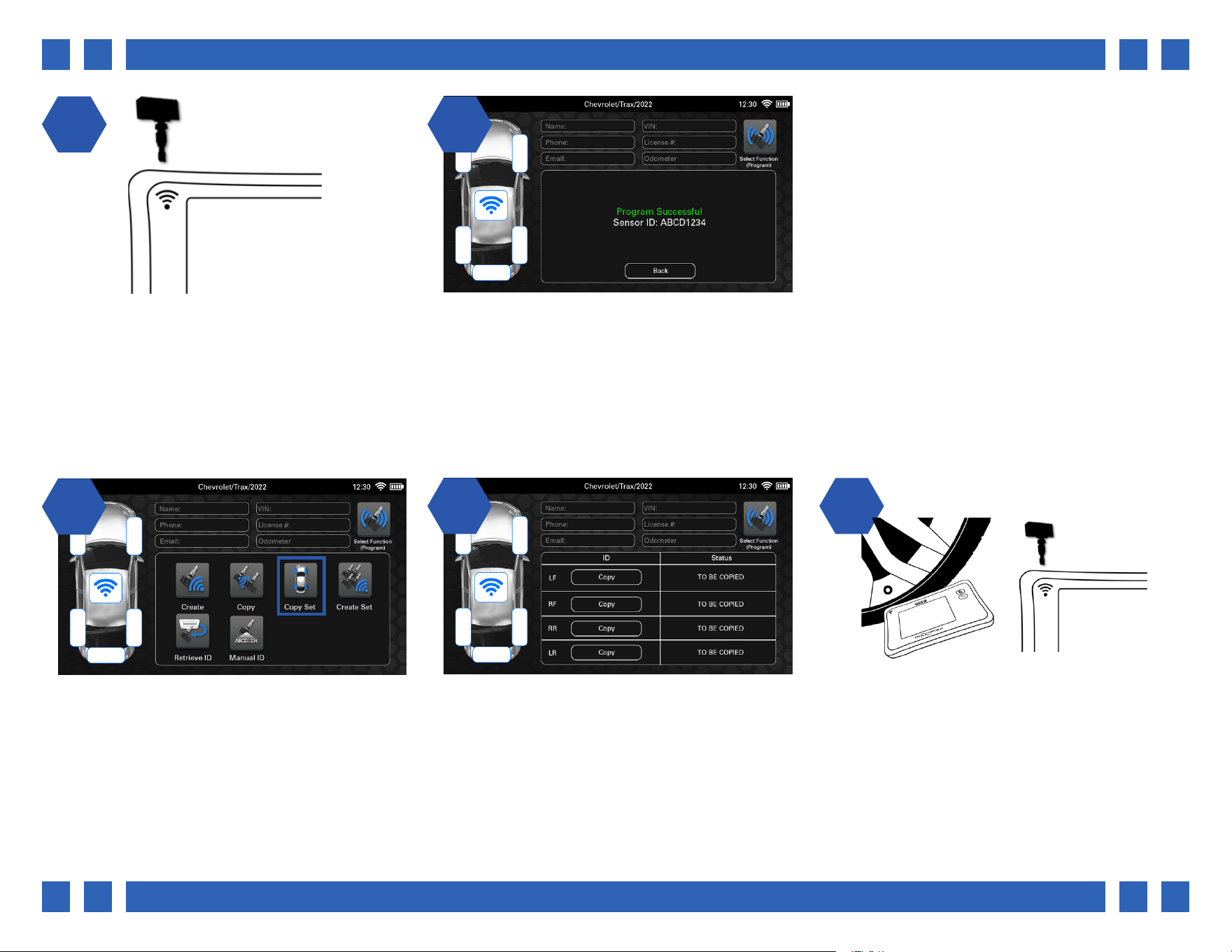
1 24 5
Continue by placing the new sensor above the
tool’s antenna and select “Program Copied ID”.
After a few moments the original sensor ID will
be programmed to the new sensor and the tool
will display “Program Successful”.
11
From the Program menu, select “Copy Set”.
4.5.3. COPY SET
2 32
The tool will display a chart with multiple
wheels, and a copy button for each sensor.
If the original sensor is still installed in the
wheel, point the tool’s antenna through the
tire sidewall and select “Copy”. If it has been
removed, place it above the tool’s antenna and
select “Copy”.
The Copy Set function is used copy the IDs from a set of existing sensors, and program them to blank aftermarket sensors.
Pg.
Pg. 16
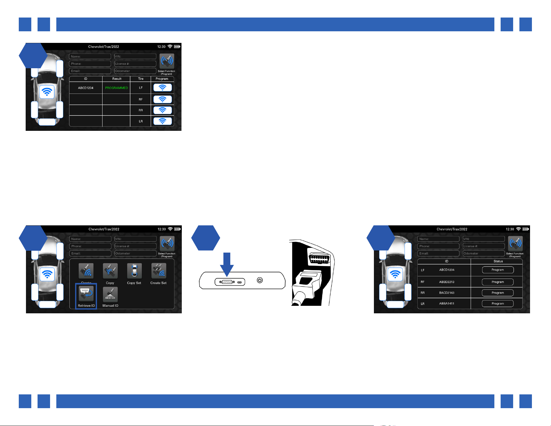
1 24 5
Once the ID has been copied, the ID will be
displayed, and the status column will allow the
ID to be copied to a new sensor.
Continue by placing the new sensor above the
tool’s antenna and select “Program”.
6
After a few moments the original sensor ID
will be programmed to the new sensor and the
tool will display “PROGRAMMED. Repeat the
process for the remaining sensors.
11
From the Program menu, select “Create Set”
22
The tool will display a chart with multiple
wheels, and a program button for each sensor.
3
Continue by placing the new sensor above the
tool’s antenna and select the program button.
4.5.4. CREATE SET
The Create Set function is used to program brand new sensor IDs to a set of blank aftermarket sensors.
Pg.
Pg. 17
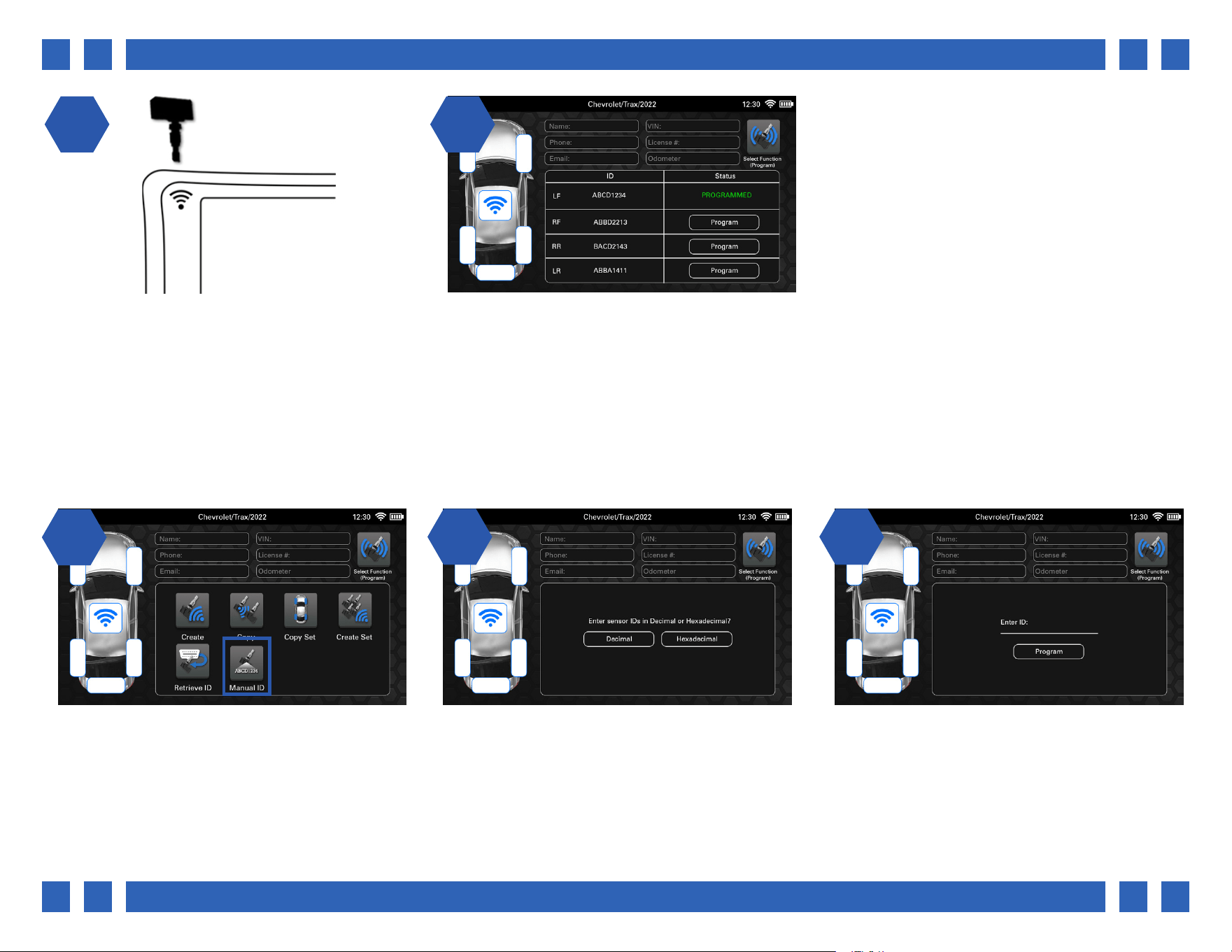
14
After a few moments the new sensor ID
will be displayed and the tool will display
“PROGRAMMED”. Repeat the process for the
remaining sensors.
11
From the Program menu, select “Retrieve ID”.
4.5.5. RETRIEVE ID
2 32
Plug the OBDII cable into the top of the tool,
and the other end into the vehicle’s OBDII port.
Select “Retrieve IDs”.
Once the IDs have been retrieved, the tool will
display a chart with all of the existing sensor
IDs in the vehicle, and a program button for
each.
The Retrieve ID function is used to retrieve the sensor IDs currently stored in the vehicle’s ECU and program them to a set of new
aftermarket sensors.
Pg.
Pg. 18
1 24 5
Continue by placing the new sensor above the
tool’s antenna and select the program button.
After a few moments the new sensor ID
will be displayed and the tool will display
“PROGRAMMED”. Repeat the process for the
remaining sensors.
11
From the Program menu, select “Manual ID”
22
Continue by selecting a ID format.
Decimal: (0-9)
Hexadecimal: (A-F) (0-9)
3
Tap the Enter ID area, and use the tool’s on-
screen keyboard to enter a sensor ID.
4.5.6. MANUAL ID
The Manual ID function is used manually enter a sensor ID and program it to a blank aftermarket sensor.
Pg.
Pg. 19
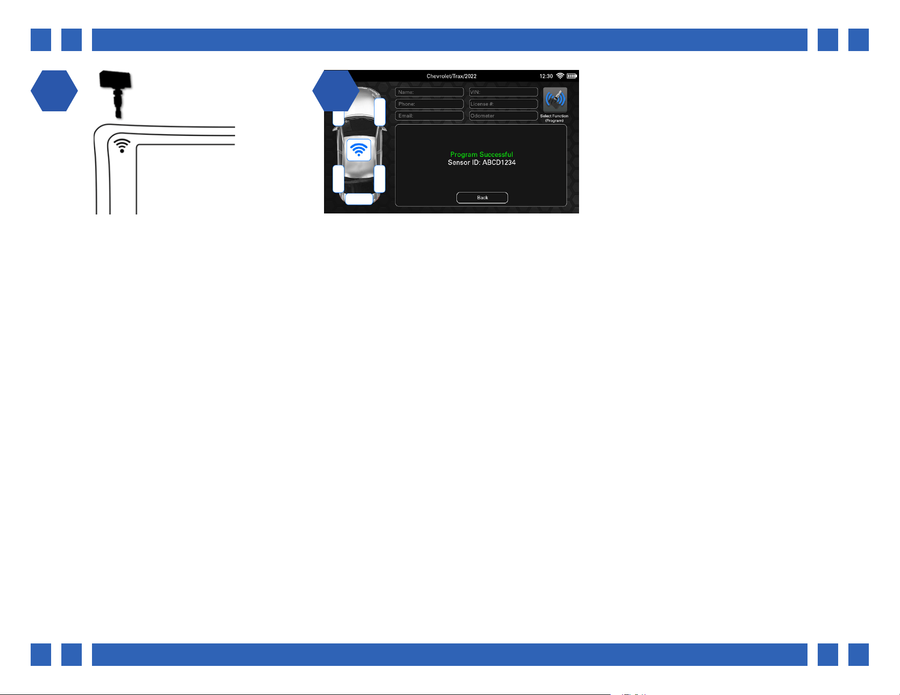
1 24 5
Continue by placing the new sensor above the
tool’s antenna and select “Program”.
After a few moments the entered sensor ID will
be programmed to the new sensor and the tool
will display “Program Successful”.
Pg.
Pg. 20
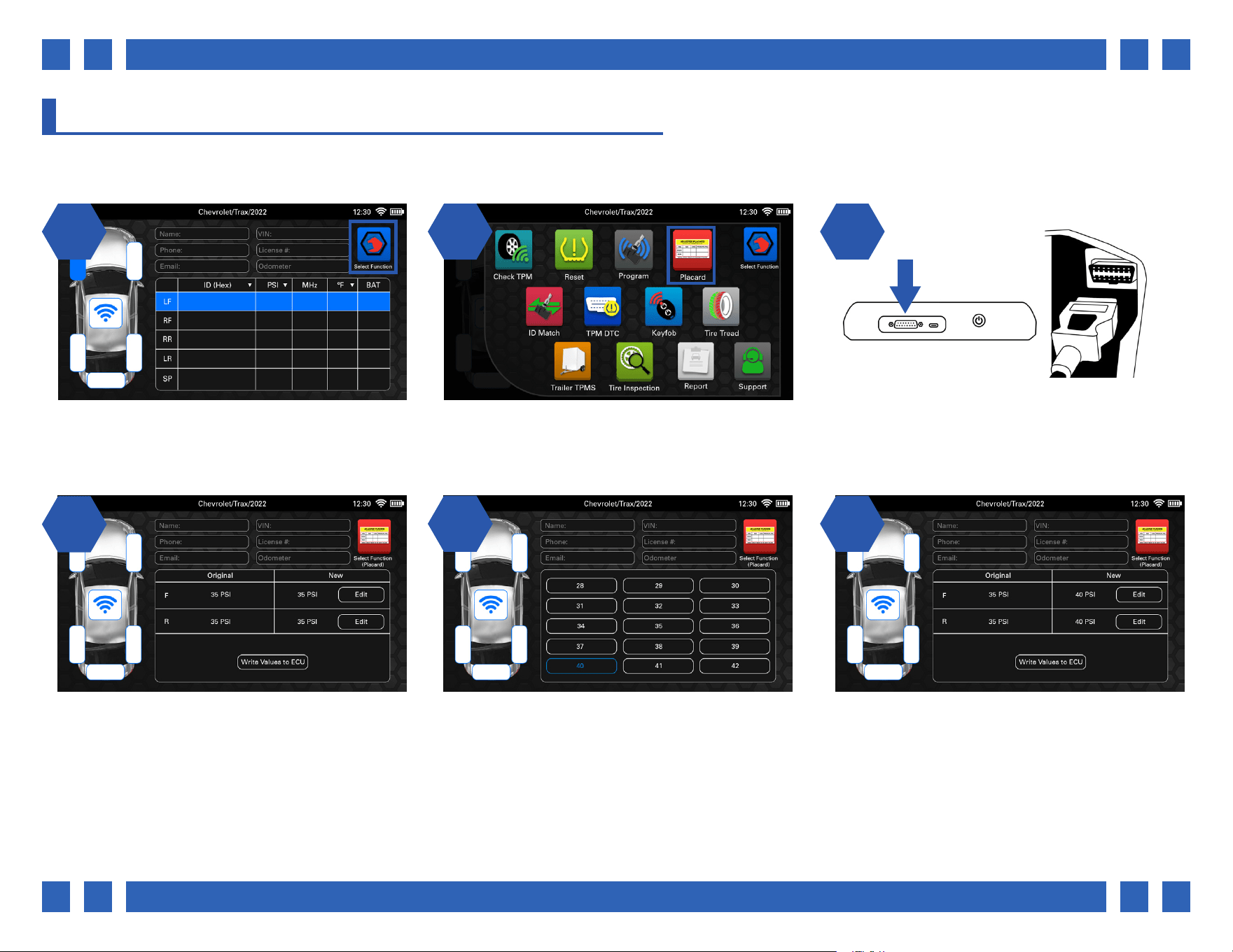
4.6. PLACARD
When changing tire sizes or load types, the Placard function can be used to edit the internal placard pressure values. This will
ensure that the TPMS light will come on at the correct pressure.
1 2 31 2
14
On the main vehicle screen, select a function
by pressing the icon on the top right corner.
From the function select menu, select “Placard”. Plug the OBDII cable into the top of the tool,
and the other end into the vehicle’s OBDII port.
Select “Read Placard”.
The tool will display the current placard
pressure values stored in the vehicle’s ECU, as
well as the new selected values. Select the Edit
button to edit the values for that axle.
25
Scroll up or down the list and select a new
value.
6
Once both axles have a new set value, select
“Write Values to ECU:.
Pg.
Pg. 21
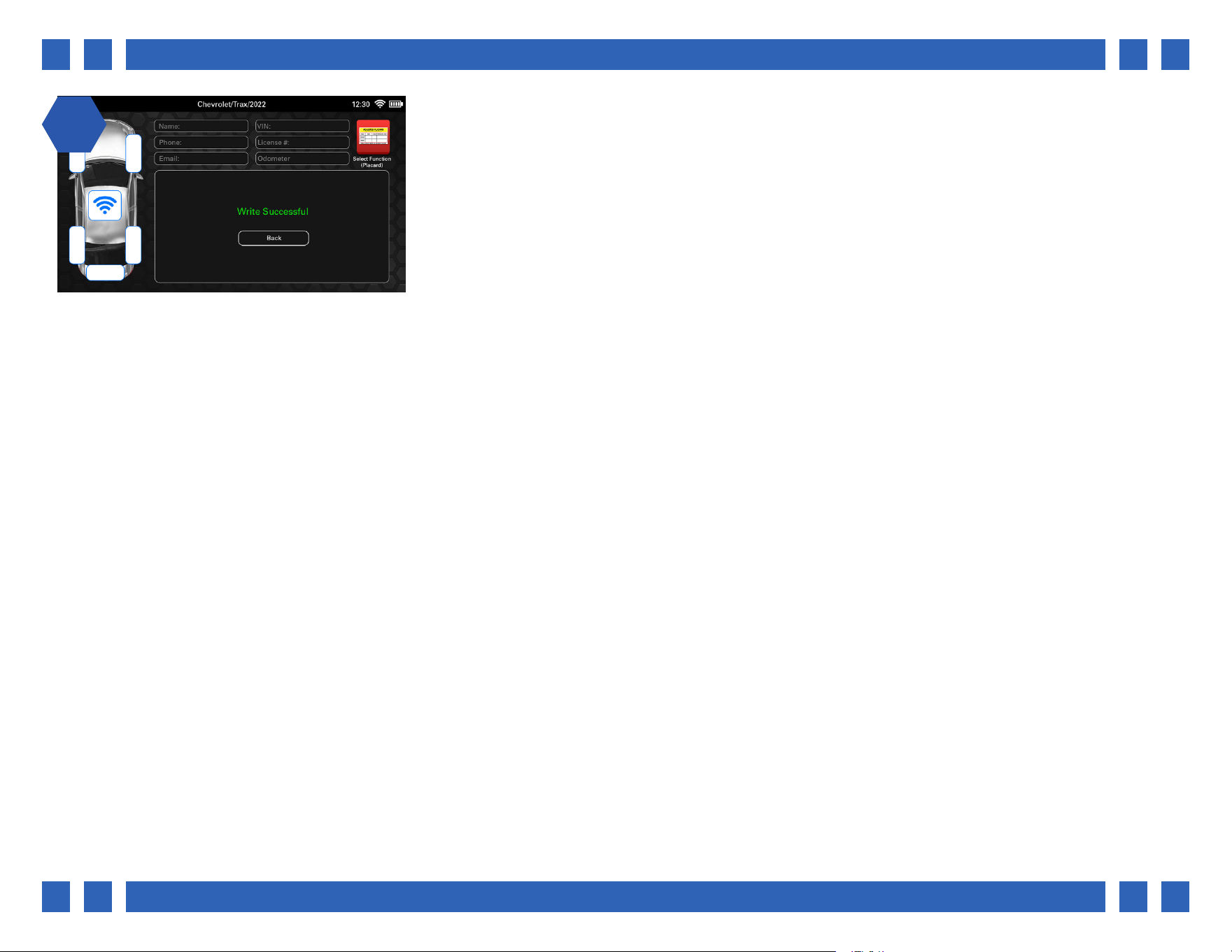
17
After a few moments the new placard values
will have been written to the ECU and the tool
will display “Write Successful”.
Pg.
Pg. 22
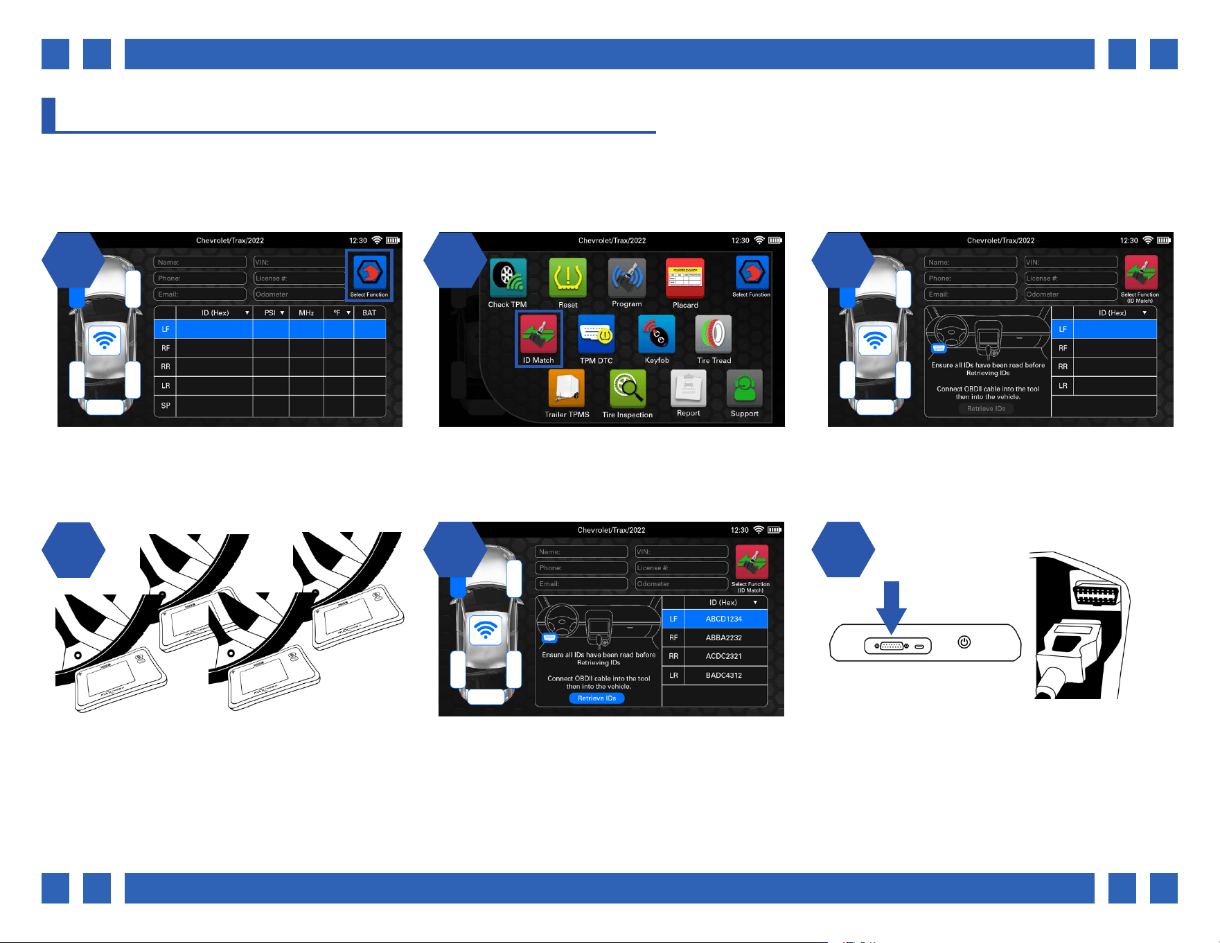
4.7. ID MATCH
In some cases, when changing tires, a relearn may not have been performed correctly, a sensor not programmed properly, or
sensors were replaced in the incorrect positions. The ID Match function allows you to scan the current sensors, then hook up to
the vehicle and compare the IDs with the ones stored in the ECU.
1 2 31 2
14
On the main vehicle screen, select a function
by pressing the icon on the top right corner.
From the function select menu, select “ID
M a t c h”.
The tool will display a chart for the scanned
sensor IDs, as well as a prompt to retrieve the
ECU IDs once nished.
Begin by scanning each sensor on the vehicle.
25
Plug the OBDII cable into the top of the tool,
and the other end into the vehicle’s OBDII port.
Select “Retrieve IDs”.
6
Once all sensors have been scanned, you will
need to plug into the vehicle to compare the
IDs.
Pg.
Pg. 23
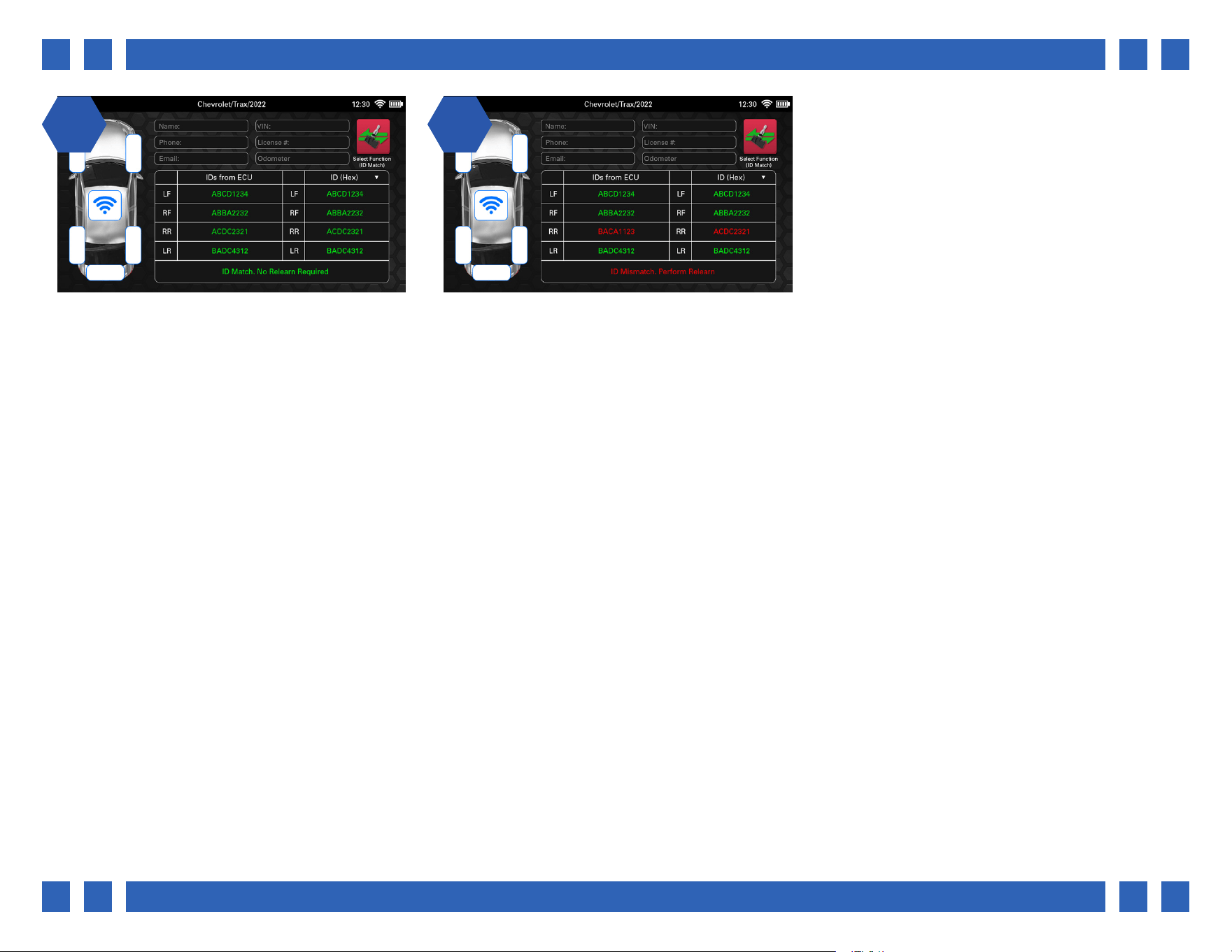
1 27 8
The tool will then compare the IDs stored in the
vehicle’s ECU to the IDs that were scanned. In
the event that they all match, no further action
is needed.
In the event that there is a mismatch, this
means that a relearn needs to be performed.
Pg.
Pg. 24
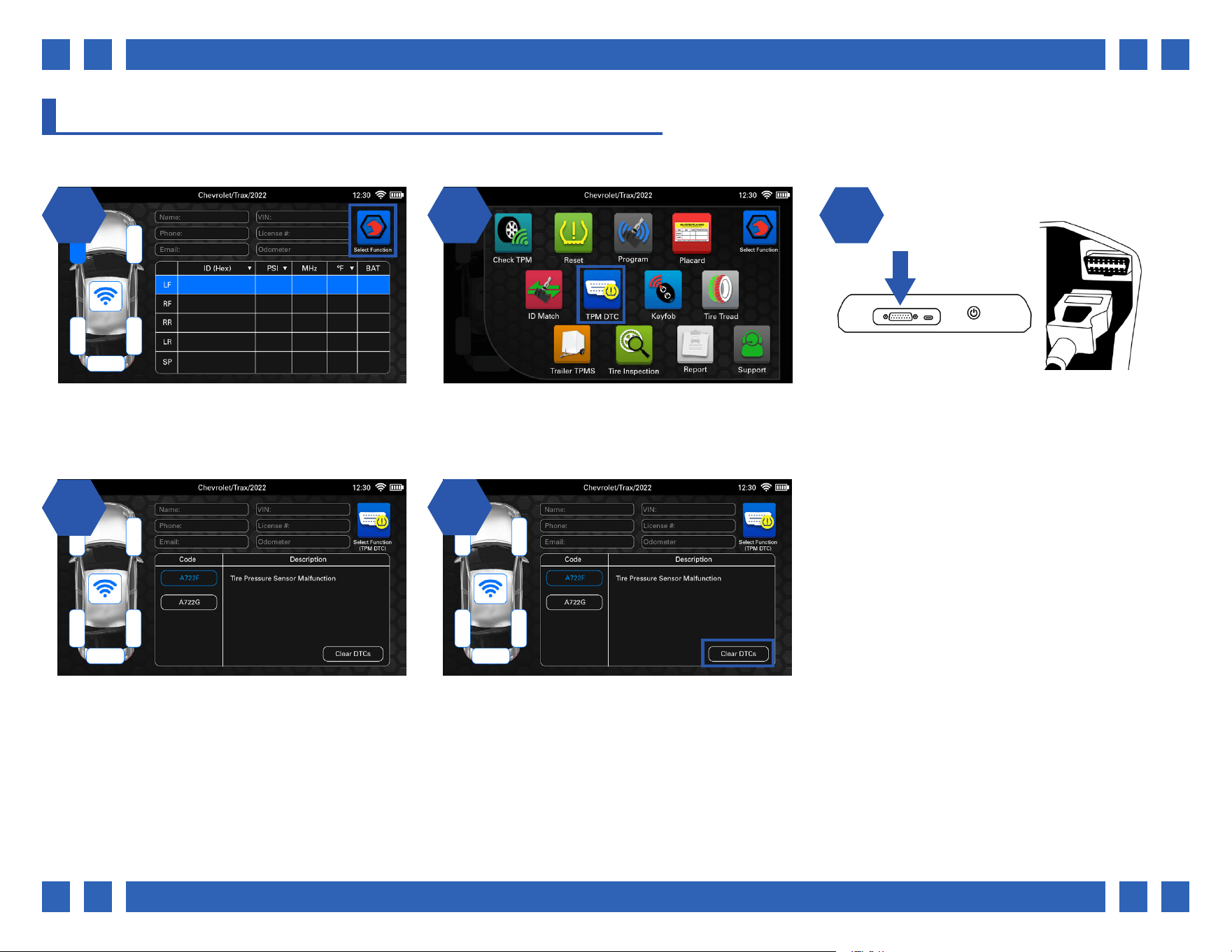
4.8. TPM DTC
The TPM DTC function can be used to scan for any potential TPMS related diagnostic trouble codes in the vehicle.
1 2 31 2
14
On the main vehicle screen, select a function
by pressing the icon on the top right corner.
From the function select menu, select “TPM
D TC ”.
Plug the OBDII cable into the top of the tool,
and the other end into the vehicle’s OBDII port.
Select “Retrieve DTCs”.
The tool will retrieve any codes within the
vehicle and will display the vehicle-specic
code, as well as a description.
25
If applicable, the Clear DTCs button can be
selected to clear the codes.
Pg.
Pg. 25
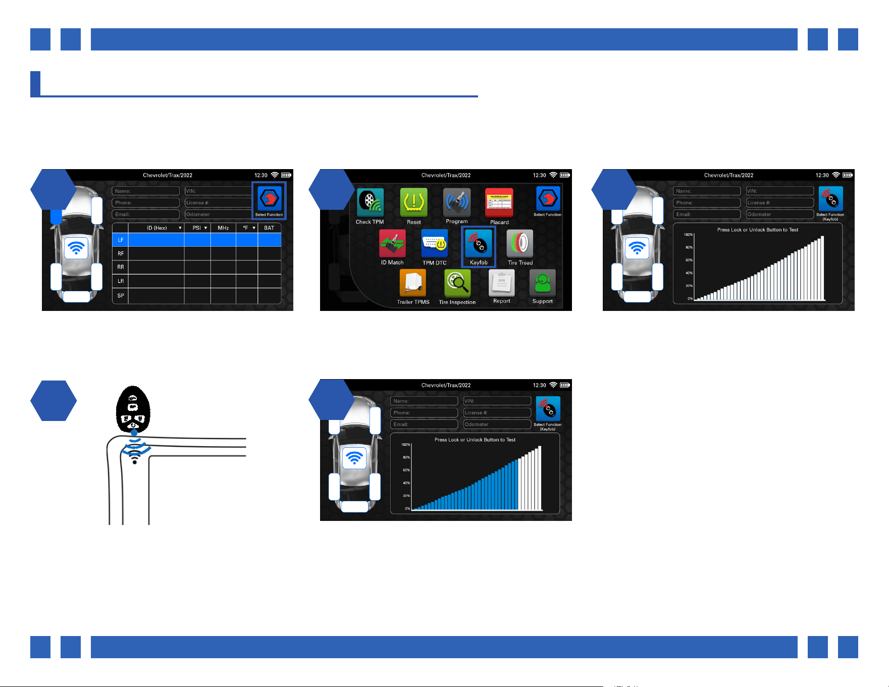
4.9. KEYFOB
The Keyfob function is used to test the signal strength of keyfobs. Many vehicles require use of its keyfob as a part of the relearn
procedure. Use this function to test if the fob is functioning properly.
1 2 31 2
14
On the main vehicle screen, select a function
by pressing the icon on the top right corner.
From the function select menu, select “Keyfob”. The tool will display a graph to show keyfob
signal strength.
Place the keyfob above the tool’s antenna and
press the lock or unlock buttons.
25
The tool will display the signal strength by
percentage. A low percentage may indicate that
the keyfobs battery needs to be replaced.
Pg.
Pg. 26
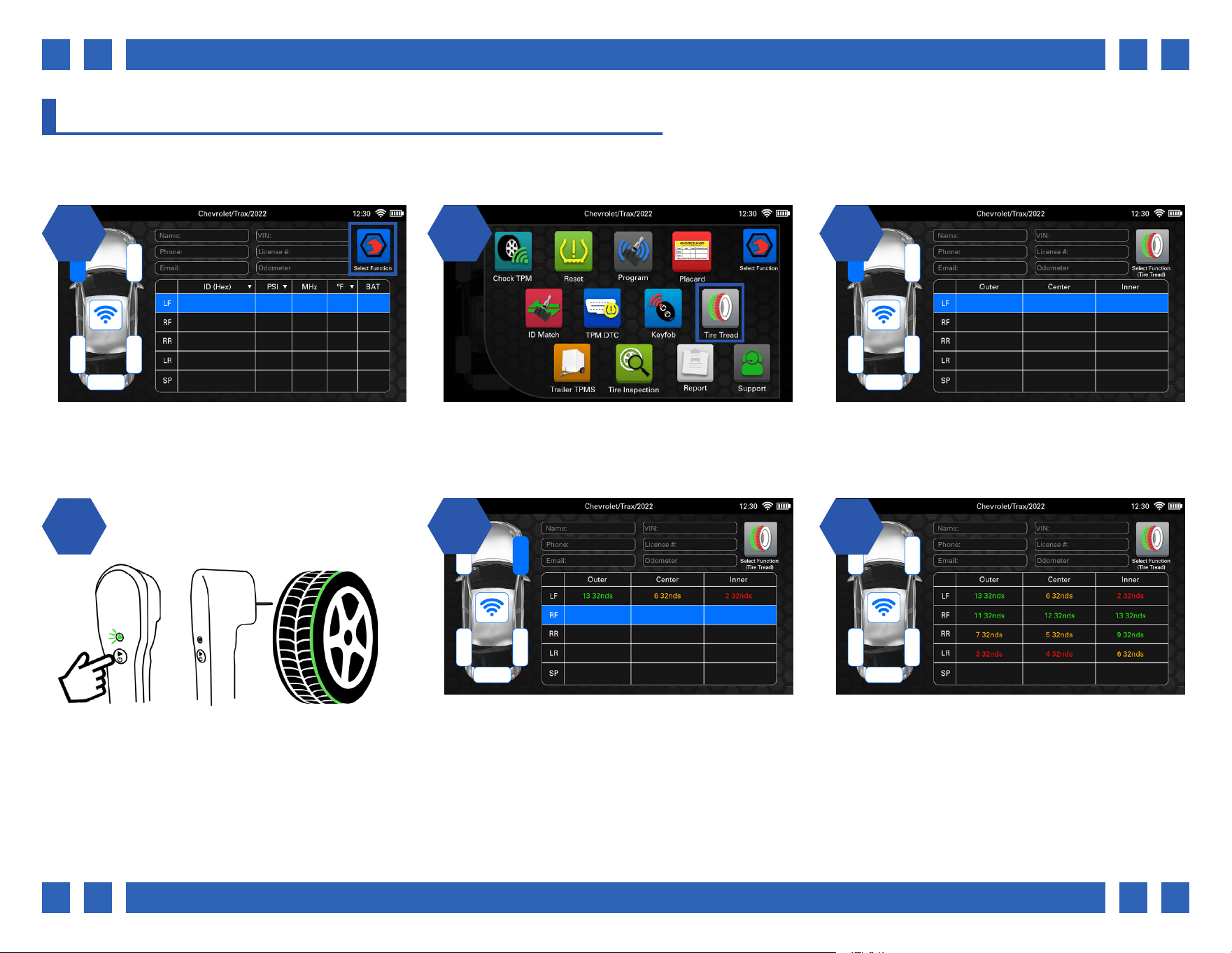
4.10. TIRE TREAD
With the optional Tire Tread Depth Gauge accessory, the Tire Tread function can be used to scan the outer, center, and inner tread
for each tire. Each tire will have a color coded display to easier identify tread wear.
1 2 31 2
14
On the main vehicle screen, select a function
by pressing the icon on the top right corner.
From the function select menu, select “Tire
Tread”.
The tool will display a chart for the outer,
center, and inner measurements for each tire.
Begin by pressing the trigger button on the
accessory. The tool will then prompt to scan the
outer, center, and inner tread. Press the pin into
each tread until the tool prompts to release and
move on to the next.
25
Once complete, the tool will display the results
by color:
Green - OK
Orange - Worn
Red - Dangerously Worn
6
Repeat the process for the remaining tires.

Pg.
Pg. 27
4.11. TRAILER TPMS
Some vehicles oer the ability to scan trailer TPMS sensors, as well as view their relearn procedures. The Trailer TPMS function can
be used to select specic axle/wheel congurations and perform trailer relearns.
1 2 31 2
14
On the main vehicle screen, select a function
by pressing the icon on the top right corner.
From the function select menu, select “Trailer
TPMS”.
Begin by selecting the amount of wheels &
tires on the trailer.
The car display will become a trailer with the
select wheel/axle conguration. Begin by
following the relearn instructions to put the
trailer into a “learn” mode.
25
Continue by scanning each sensor in the
order listed in the instructions to complete the
relearn procedure.

Pg.
Pg. 28
4.12. TIRE INSPECTION
The Tire Inspection function can be used to document various tire information for each wheel on the vehicle. Recall status can also
be checked online by entering the tire’s DOT.
1 2 31 2
14
On the main vehicle screen, select a function
by pressing the icon on the top right corner.
From the function select menu, select “Tire
Inspection”.
A drop-down menu will be displayed for each
wheel. Begin by selecting a wheel.
Various information about the tire can be
entered such as DOT, Tire Brand, and Tire
Size. Tap an area and use the tool’s on-screen
keyboard to enter information.
25
By selecting the “Check Recall Status” button,
any recall information regarding that tire can
be checked online by entering the tire’s DOT on
the website.

Pg.
Pg. 29
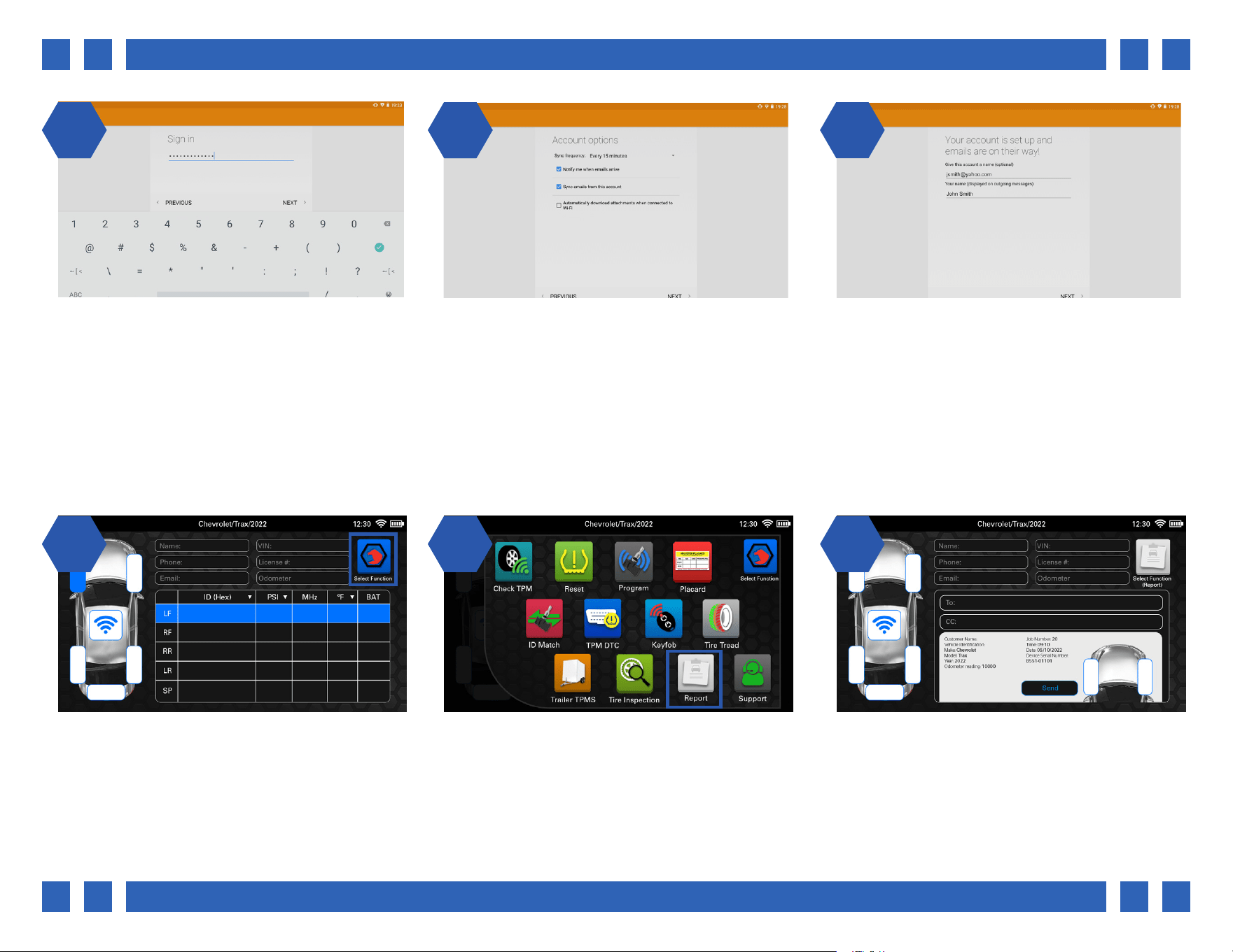
4.13. REPORT
View and email an extensive vehicle report that includes all aspects of the job including: Customer information, TPMS sensor
data, tread depth readings, and more. In order to send email reports, an email account must be set up and the tool must be
connected to WiFi. For information about connecting to WiFi, see section 3.
1 2 31 2
14
From the main menu of the tool, select
“Settings”.
From the Settings menu, select “Device
Settings”.
From the device settings, scroll down and
select “Accounts”.
Next, select “Add Account”.
25
Next, select the type of Email account to setup.
In most cases, this will be Personal (IMAP).
4.13.1. SETTING UP AN EMAIL ACCOUNT
An email account must be set up before an email report can be sent from the tool.
6
Next, enter your email address using the tool’s
on-screen keyboard and select NEXT.
Pg.
Pg. 30
1 2 97 8
Now enter the Password for your email
account.
Select any email settings you wish to use and
select “NEXT’.
Your Email account has been successfully
setup. Press the back button on the front of the
tool to return to the tool’s settings.
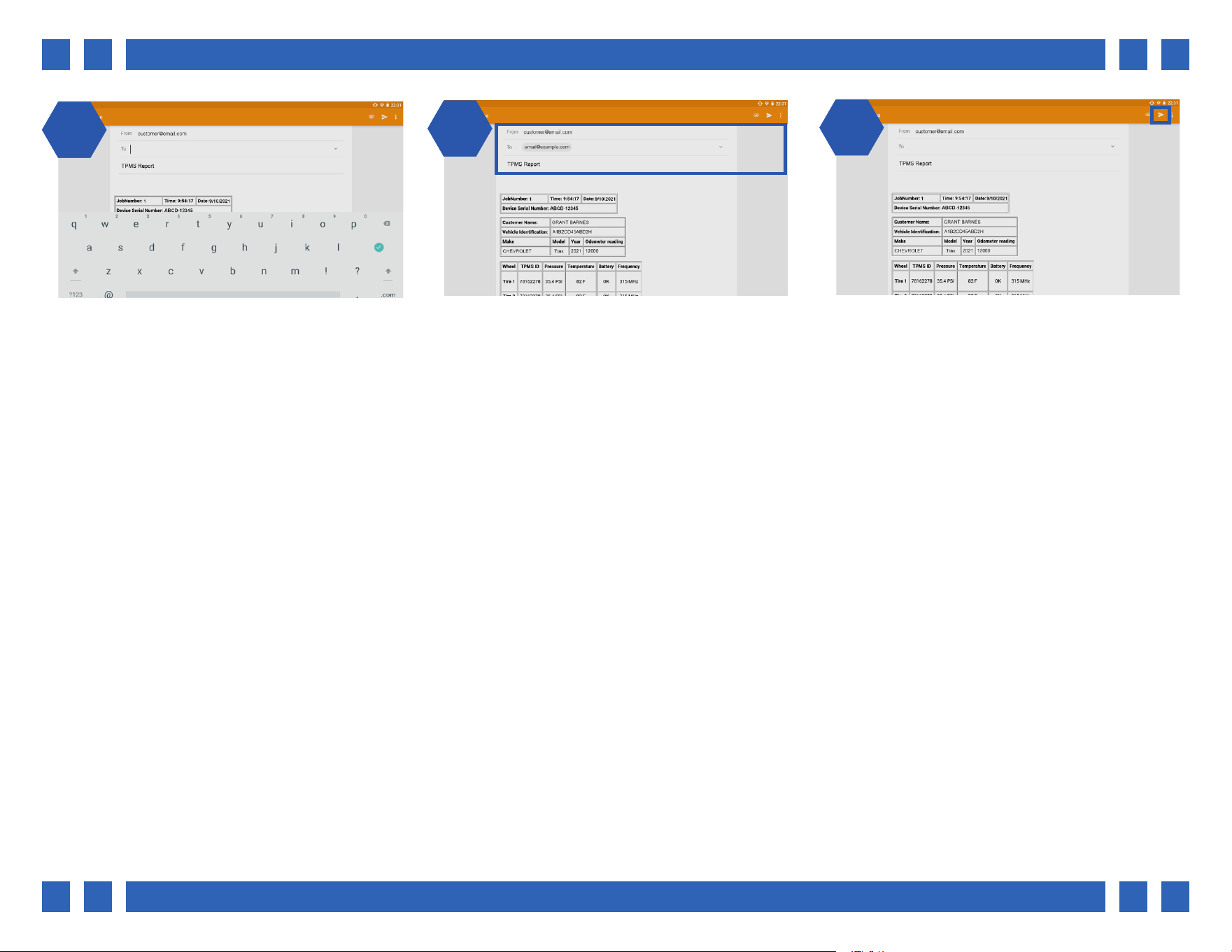
4.13.2. SENDING AN EMAIL REPORT
After an email account has been set up, TPMS reports can now be sent from the tool. Reports contain all job information, sensor
data, tread readings, and more. If an email account has not been set up yet, see the previous section 4.13.1.
1 2 31 2
On the main vehicle screen, select a function
by pressing the icon on the top right corner.
From the function select menu, select “Report”. The tool will display a full job report with all
customer and vehicle information. To send the
report, enter a recipient and select “Send”.
Pg.
Pg. 31
14
The email screen will be displayed. This screen
will display a report preview, as well as an
attached report to the email as a PDF.
25
The recipient(s) and subject can be changed
from this screen if needed.
6
Once nished, select the small paper airplane
icon at the top right to send the report.
Pg.
Pg. 32
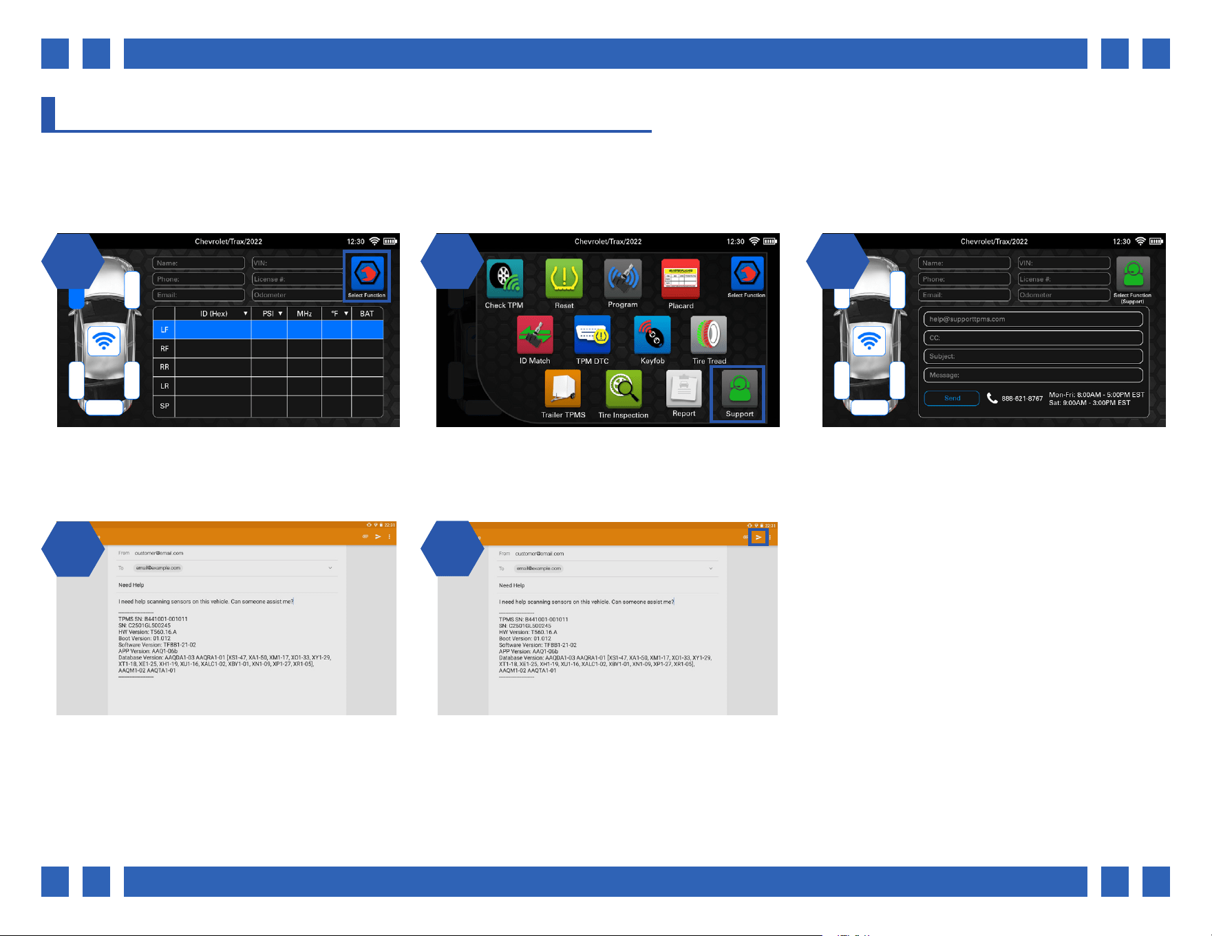
4.14. SUPPORT
The tool has the ability to email technical directly from the Support function. The technical support phone number and hours are
also available here. Note: This function requires that an email account is setup. If an email account has not been set up yet, see
section 4.13.1.
1 2 31 2
14
On the main vehicle screen, select a function
by pressing the icon on the top right corner.
From the function select menu, select
“Support”.
The tool will display an email screen with all
technical support information. Enter a subject
and a message, then select “Send”.
A support email will be generated with your
subject and message. As well as your tool’s
information to help the support team.
25
Once ready, select the small paper airplane
icon at the top right to send the support email.

Pg.
Pg. 33
5. UPDATE
It is important to keep the tool up-to-date in order to receive the latest vehicle and sensor coverage. This section is dedicated to
registering and updating the tool. The tool must be connected to WiFi in order to register and update. See section 3.
1 2 31 2
From the main menu, select “Update”. The tool will display the update screen, with
areas for registration and update information.
If this is your rst time updating the tool, you
will need to enter your registration information.
Tap each area to enter information.
Tool Serial #
Current Version
Available Version
Update Tool
Enter Software Subscription Code
Registration Information
Pg.
Pg. 34
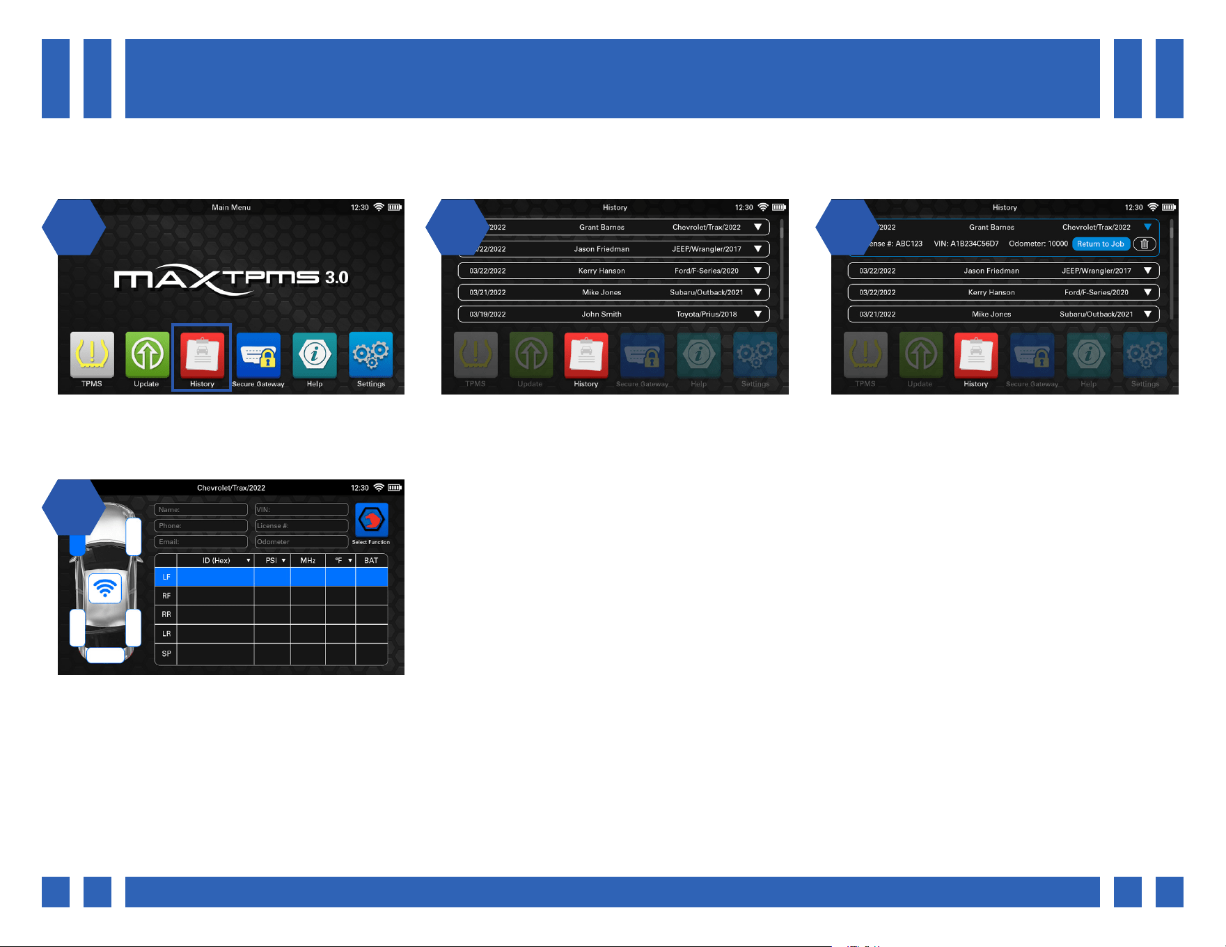
1 2 31 2
14
From the main menu, select “History”. The tool will display all of the previous jobs
performed, tap a job to view its information.
All of the selected job’s information will be
displayed, as well as a “Return to Job” button,
and a delete button.
By selecting “Return to Job” you can view and
edit any information regarding that job.
6. HISTORY
The history function allows access to the tool’s job history information, as well as the ability to return to any previous job.
ABCD1234 36.1 315 75 OK
ABBA1113 35.9 315 73 OK
CABD2243 35.1 315 73 OK
BACA1337 36.3 315 74 OK

Pg.
Pg. 35
7. SECURE GATEWAY
Many modern vehicles have added security in order to access OBDII information. The secure gateway function allows you to login
to an AutoAuth account in order to be able to perform OBDII work on these vehicles. The tool must be connected to WiFi in order
to access secure gateway vehicles. See section 3.
1 2 31 2
From the main menu, select “Secure Gateway”. The tool will display a screen to login to your
AutoAuth account, as well as view instructions
on how to perform this process.
By selecting the question mark icon, AutoAuth
setup instructions can be viewed.
Note: AutoAuth is a paid service for shops/individuals to have access to secure gateway vehicles. If you do not already have an
AutoAuth account, one can be created at webapp.autoauth.com
When adding a tool to your AutoAuth account, you will need it’s serial number. The serial number can be found on the back of the
tool itself, or in Settings > About.

Pg.
Pg. 36
1 21 2
From the main menu, select “Help”. The tool will display all of the various help
functions.
User Manual: View the user manual directly
from the tool.
FAQ: View various troubleshooting and help
tips.
8. HELP
The help function can be used to view informational material such as the user manual, help tips, videos, and more.
Training: View various videos about tool
functionality.
Support: View technical support information,
as well as email support. For more information,
see section 4.13.1.

Pg.
Pg. 37
9. SETTINGS
1 21 2
From the main menu, select “Settings”. The tool will display the settings screen.
Language
Region
The settings function is used to change various settings, as well as view tool information.
- Change the tool’s display language from over 10 languages.
- Change the tool’s working region.
Units
- Change pressure/temperature/tread/ID format units.
Background
- Change the color of the tool’s background.
(Grey/Green/Orange/Blue)
About
- View various tool information such as serial number,
software version, and more.
Device Settings
- Change settings regarding the device itself. Screen
brightness, WiFi, Accounts, etc.

Pg.
Pg. 38
10. WARRANTY
MATCO TOOLS LIMITED PRODUCT WARRANTY
Any tool or part branded with the Matco Tools (MATCO) name is warranted against defects in materials and workmanship. Matco,
or one of its authorized representatives, will, at Matco’s option, repair, or replace, any tool or part bearing the MATCO name,
without charge, if the defective or malfunctioning tool or part is returned to Matco or one of its authorized representatives. Please
be sure to include your name and address with the tool or part, and describe the nature of the problem.
To return a product through matcotools.com you must rst Register as a user. You can then Login.
Once registered and logged in, returns can be processed through the Your Account link in the upper right corner of any
matcotools.com page.
Matco shall have no obligation pursuant to the Matco Warranty with respect to any tools or parts which in Matco’s sole judgment
have been altered damaged, misused, abused, badly worn, lost or improperly maintained. This Warranty is null and void if the
customer, or any other person other than an authorized representative of Matco, has made any attempt to service or modify the
tool prior to its return to Matco under this Warranty.
All products sold by Matco to its Distributors are assigned a warranty code in the Matco Price List. The limited warranty provision
with respect to each such product shall be the limited warranty designated in this warranty code agreement and may be amended
by Matco from time to time in its sole discretion.
Matco Tools reserves the right to make periodic changes in construction or tool design at any time. Matco specically reserves
the right to make these changes without incurring any obligation or incorporating such changes or updates in tools or parts
previously distributed.
The Matco Warranty is in lieu of all other warranties, expressed or implied, including any warranty of merchantability or tness
for a particular purpose, and sets forth the sole and exclusive remedy in contract, tort, strict liability, or otherwise. Under no
circumstances shall Matco be liable for any special, incidental, or consequential damages.
Note: Some states do not allow the exclusion or limitation of incidental or consequential damages. The Matco Warranty confers
specic legal rights. The purchaser may have other rights which vary from state to state or outside the United States of America.
Throughout our on-line catalog. These tips are provided only as a convenience to our customers and we in no way imply that it is
a complete list of all tool safeguards and precautions. We suggest you refer to the manufacturer’s instructions when provided.

Pg.
Pg. 39
No Matco employee, distributor or other person, other than an authorized ocer of Matco, may extend the Matco Warranty. Any
such alteration must be in writing and signed by such ocer.
MISUSED AND ABUSED PRODUCT
Over time, Matco’s hand tools and service equipment have earned a reputation for world-class quality, superior workmanship,
and professional-grade durability. When properly used and conscientiously maintained, Matco tools can provide you their full
lifetime of reliable service. However, this is not to say that our tools are indestructible. When subjected to intentional physical
misuse and abuse, even Matco tools can break or fail prematurely.
Matco Tools and our Matco Distributors recognize that the warranty coverage which we oer on our tools and equipment has a
signicant inuence on your decision to purchase and use Matco products. We also recognize that the intentional misuse and
abuse of hand tools continues to be a common concern to us all. As a result of both considerations, Matco has structured our
warranty policies and product guarantees accordingly. While eminently fair by industry standards, Matco’s Warranty reserves the
right to exclude products which have been obviously and intentionally misused and abused.
IMPORTANT NOTICES
Product Changes: Matco reserves the right to make changes in design, appearance and construction of any and all products listed
herein without incurring any obligation in making such changes in products previously sold or transferred. MATCO also reserves
the right to discontinue the availability of any products at such time as such action is considered necessary.
Liability: Matco cannot accept the responsibility for the results of using tools which have been abused or badly worn. MATCO
also cannot accept responsibility for results of using tools incorrectly or using tools which have been improperly repaired or
maintained.
Safety Tips: Matco encourages tool safety and proper tool use. We have provided various safety tips and proper tool usage tips
throughout our on-line catalog. These tips are provided only as a convenience to our customers and we in no way imply that it is a
complete list of all tool safeguards and precautions. We suggest you refer to the manufacturer’s instructions when provided.