1
• For Outdoor Use Only (outside
any enclosure).
• This instruction manual
contains important information
necessary for proper assembly
and safe use of this appliance.
• Read and follow all warnings
and instructions before
assembling and using the
appliance.
• Follow all warnings and
instructions when using the
appliance.
• Keep this manual for future
reference.
• If you smell gas:
1. Shut off gas to the appliance.
2. Extinguish any open ames.
3. Open the lid.
4. If the odor continues, keep
away from the appliance and
immediately call your re
department.
• Do not store or use gasoline
or other ammable liquids or
vapors in the vicinity of this or
any other appliance.
• An LP cylinder not connected
for use shall not be stored in
the vicinity of this or any other
appliance.
DANGER
WARNING
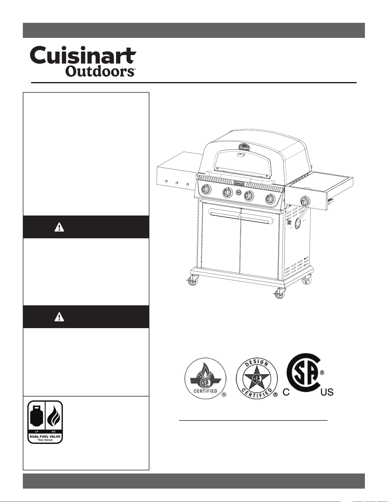
MODEL NO: CGG-6331
Propel+ Four Burner 3-in-1 Gas Grill
DO NOT RETURN PRODUCT TO THE STORE
Before visiting your local retailer, please email
[email protected] or call our customer service
department at 1-866-994-6390 to chat with a representative.
To best serve you, our representatvies are available to answer
calls Monday to Friday 9 AM to 5 PM EST.
Customer Service Hotline
1-866-994-6390
This grill is designed with
dual-fuel capability to
convert from LP (propane
gas) to NG (natural gas).
Cuisinart Outdoors offers
a (*)NG conversion kit
#QG-2186. Available at Cuisinart.com or
call our customer service department at:
1-866-994-6390 (*Sold Separately)
ANSI Z21.58-2022 • CSA 1.6-2022

2
Table of Contents
Table of Contents 2
Safety Information 3
What’s In The Box 5
Assembly Instructions 6
Setup Instructions 23
Operating Instructions For Propel+ 25
Care and Maintenance 28
Trouble Shooting 30
Match Light Instructions 33
Exploded View 34
Parts List 35
Warranty & Replacement Parts Back Cover
3
SAFETY INFORMATION
• The installation must conform with local codes or, in the absence of local codes either ANSI Z223.1/NFPA 54, CSA B149.1,
or CSA B149.2
• This outdoor cooking gas appliance must only be used outdoors and must not be used in a building, garage, or any other
enclosed area.
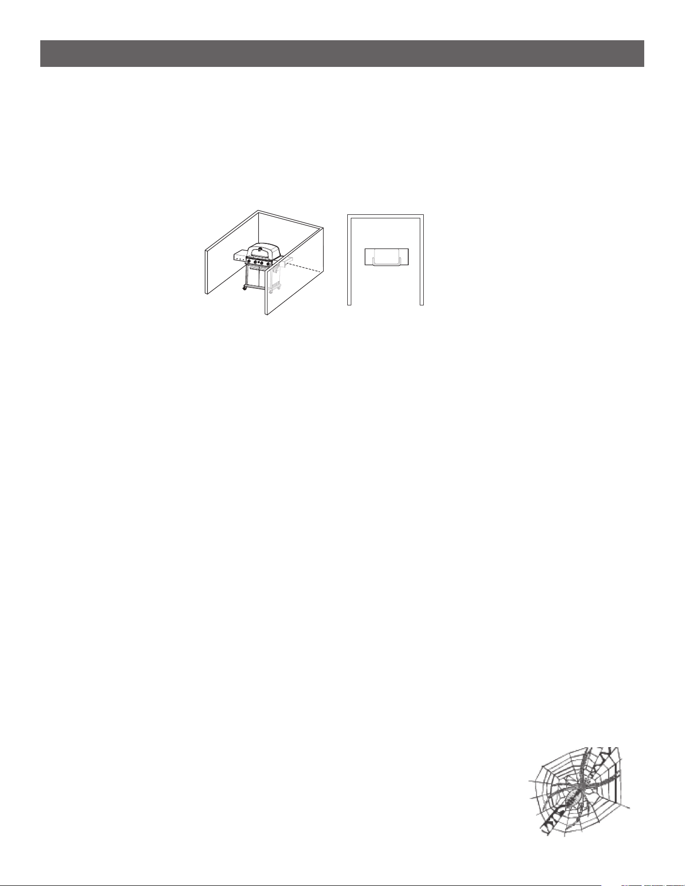
• An appliance is considered to be outdoors if installed with shelter no more inclusive than with walls on three sides, but with
no overhead cover; all openings must be permanently open; sliding doors, garage doors, windows, or screened openings are
not considered as permanent openings.
• This outdoor cooking gas appliance is not intended to be installed in or on boats or on recreational vehicles.
• A minimum clearance of 36 inches from combustible constructions to the sides of the grill and 36 inches from the back of
the grill to Combustible constructions must be maintained.
• Do not use this appliance under an overhead combustible construction.
• Inspect the hose before each use of the outdoor cooking gas appliance. If it is evident that there is excessive abrasion or
wear, or the hose is cut, it shall be replaced prior to the outdoor cooking gas appliance being put into operation. Please use
the contact information on the front cover to reach our customer service team for any replacement parts.
• Keep any electrical supply cord and the fuel supply hose away from any heated surfaces.
• Keep the outdoor cooking gas appliance area clear and free from combustible materials, gasoline, and other ammable
vapours and liquids.
• Do not obstruct the ow of combustion and ventilation air around the burner box.
• Keep the ventilation openings of the cylinder enclosure free and clear from debris.
• Do not use the grill unless it is COMPLETELY assembled, and all parts are securely fastened and tightened.
• After a period of storage and/or nonuse, check for leaks, burner obstructions and inspect for any abrasion, wear, cuts to the
hose.
• This appliance is not intended for commercial use.
• The use of alcohol, prescription, or non-prescription drugs may impair the consumer’s ability to properly assemble or safely
operate the appliance.
• When cooking with oil or grease, have a type BC or ABC re extinguisher readily available.
• Do not move the appliance when in use. Allow the cooking vessel to cool to 115°F (45 °C) before moving or storing.
• Do not store a spare LP gas cylinder under or near this appliance.
• Never ll the cylinder beyond 80 percent capacity.
• If these instructions are not followed exactly, a re causing death or serious injury may occur.
• The minimum operating temperature for safe use of the grill is -4°F (-20°C).
NATURAL HAZARD • SPIDERS
FACT: Sometimes spiders and other small insects climb into the burner tube. The spiders spin webs, build nests and lay eggs.
The webs or nests can be very small, but they are very strong and can block the ow of gas. Clean
burner prior to use after storing, at the beginning of outdoor cooking season or after a period of one
month not being used.
SAVE THESE INSTRUCTIONS
FOR OUTDOOR HOUSEHOLD USE ONLY
4
SAFETY INFORMATION
The Fuel System
• Gas appliances are used safely by millions of people when following simple safety precautions. This appliance is
congured for liquid propane. To use natural gas, please install the Cuisinart NG conversion Kit QG-2186.
• The components in the fuel system including the pressure regulator and hose are designed for operation with
this Grill. They must not be modied or replaced by components from other brands. (See replacement parts list
on page 35 for manufacturer approved components.)
Total gas consumption when set to “High”: 44,000 BTU/Hr.
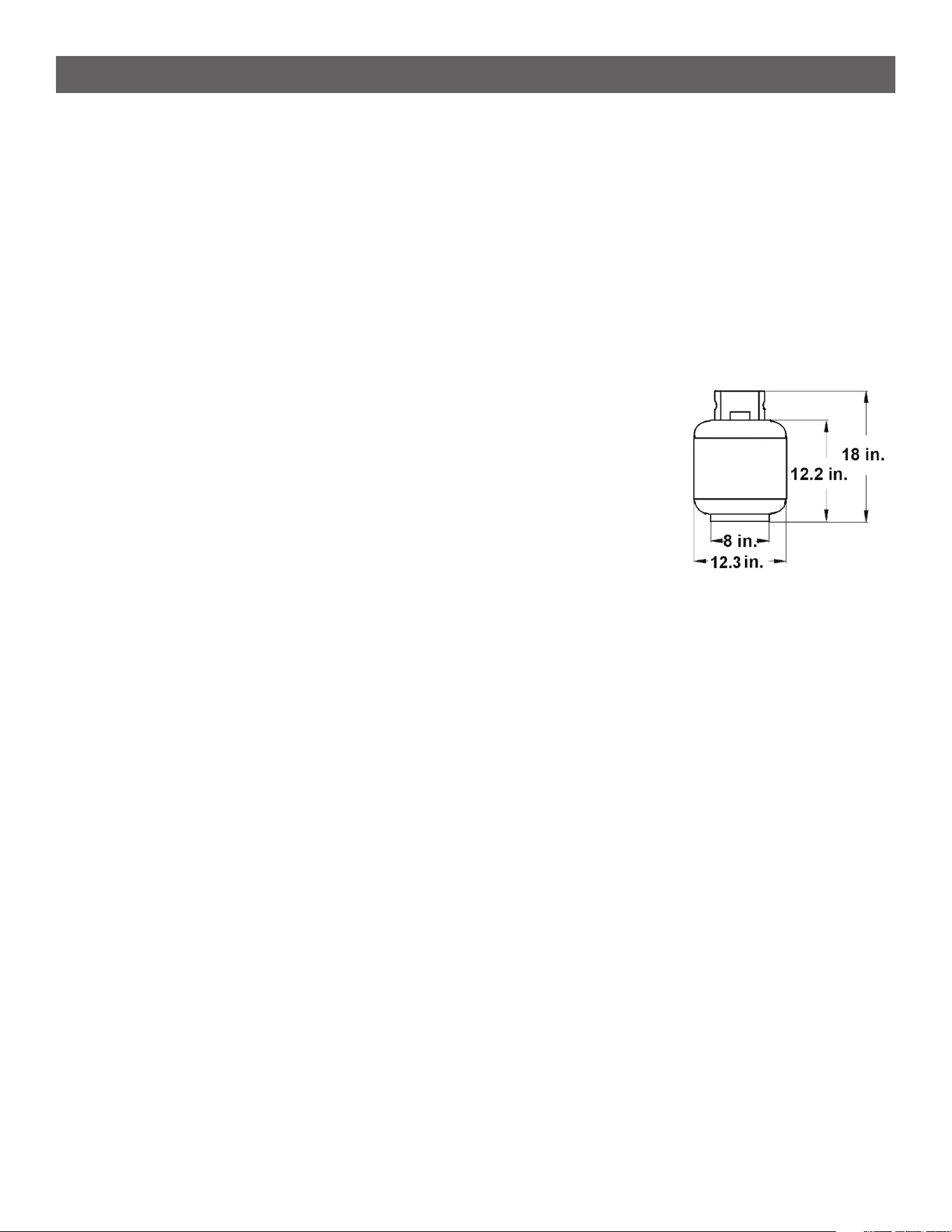
Liquid Propane (LP) Cylinder Requirements
(20-lb Cylinder)
• The approximate specications of an approved LP cylinder is 18 inches high,
12.3 inches in diameter and marked for 20 pounds of liquid propane gas
capacity or 47.6 pounds of water capacity. Provided with a listed overlling
prevention device. Provided with a cylinder connection device compatible with
the connector for outdoor cooking appliances.
• The Liquid Propane cylinder must be constructed and marked in accordance
with the specications for Liquid Propane cylinders by the United States
Department of Transportation (DOT) or the National Standard of Canada, CAN/
CSA-B339, Cylinders, Spheres and Tubes for Transportation of Dangerous
Goods Commission.
• A dented or rusty Liquid Propane cylinder may be hazardous and should be checked by your supplier. Never use
a cylinder with a damaged valve.
• The 20-lb cylinder must have a shut off valve terminating in a valve outlet specied, as applicable, for connection
type QCC1 in the standard for compressed gas cylinder valve outlet and inlet connection ANSI/CGA-V-1.
• When appliance is not in use always turn off the gas at the liquid propane cylinder.
• Storage of an outdoor cooking gas appliance indoor is permissible only if the cylinder is disconnected and
removed from the outdoor cooking gas appliance.
• Liquid propane cylinders must be stored outdoors out of the reach of children. They shall not be stored in a
building, garage, or any other enclosed area.
• The cylinder system must be arranged for vapor withdrawal.
• The cylinder must include a collar to protect the cylinder valve.
• Manifold pressure: (operating) 11 inches water column (W.C.), (non-operating) 11.2 inches water column (W.C.).
• The liquid propane cylinder must be tted with an Overll Protection Device (OPD) and a CGA 791 tank
connection.
• Place dust cap on cylinder valve outlet whenever the cylinder is not in use. Only install the type of dust cap
on the cylinder valve outlet that is provided with the cylinder valve. Other types of caps or plugs may result in
leakage of propane. Remove this cap before use.
• Make sure the gas hose does not contact hot surfaces like the burner shield when the Liquid Propane cylinder is
positioned for use.
5
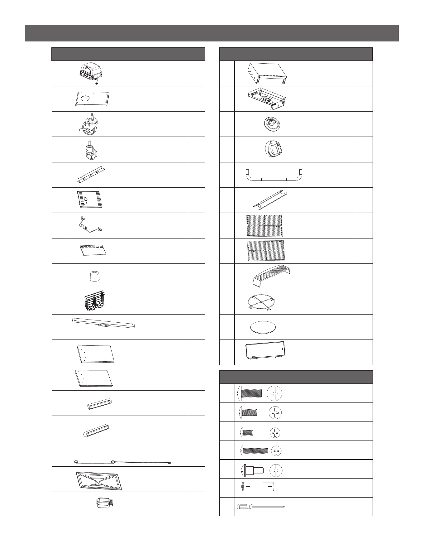
WHAT’S IN THE BOX
1
Cabinet Base
Grill Body 1
1
2
2
3
24
Locking Casters
Casters
Cabinet Side Panel
Propane Tank Wire
25
26
Drip Tray Bracket
17
Cabinet Rear Panel
18
Door Bumper
19
Accessory Rack
310
Cabinet
Front Beam
111
Cabinet Left Door
Cabinet Right Door
12
1
13
Left Door Handle
Match Lighter
Right Door Handle
1
14
1
15
Drip Tray
1
16
1
17
Left Side Table
1
18
Right Side Table
PART COMPONENT DESCRIPTION QTY
19
Knob Bezel
1
1
20
21
1
22
Knob
Lid Handle
Flame Tamers
5
23
1
24
Grill Grate Left
4
25
Grill Grate Right
1
26
Warming Rack
1
27
Pizza Stone Holder
1
28
Pizza Stone
1
29
Griddle Plate
1
30
1
PART COMPONENT DESCRIPTION QTY
Phillips Head Screw
M6x16
29
Phillips Head Screw
M5x12
Phillips Head Screw
M4x8
Phillips Head Screw
M4x20
Shoulder Bolt
M5
4
A
AA Battery
B
14
1
1
1
C
D
E
F
1
G
PART HARDWARE DESCRIPTION QTY
2
Grease Cup
11” Phillips Head
Screwdriver
6
ASSEMBLY INSTRUCTIONS
Before beginning assembly, installation or operation of product, make sure all parts are present. Compare parts
with the “what’s in the box” list. If any part is missing or damaged, do not attempt to assemble, install or operate
the product. Contact customer service for replacement parts.
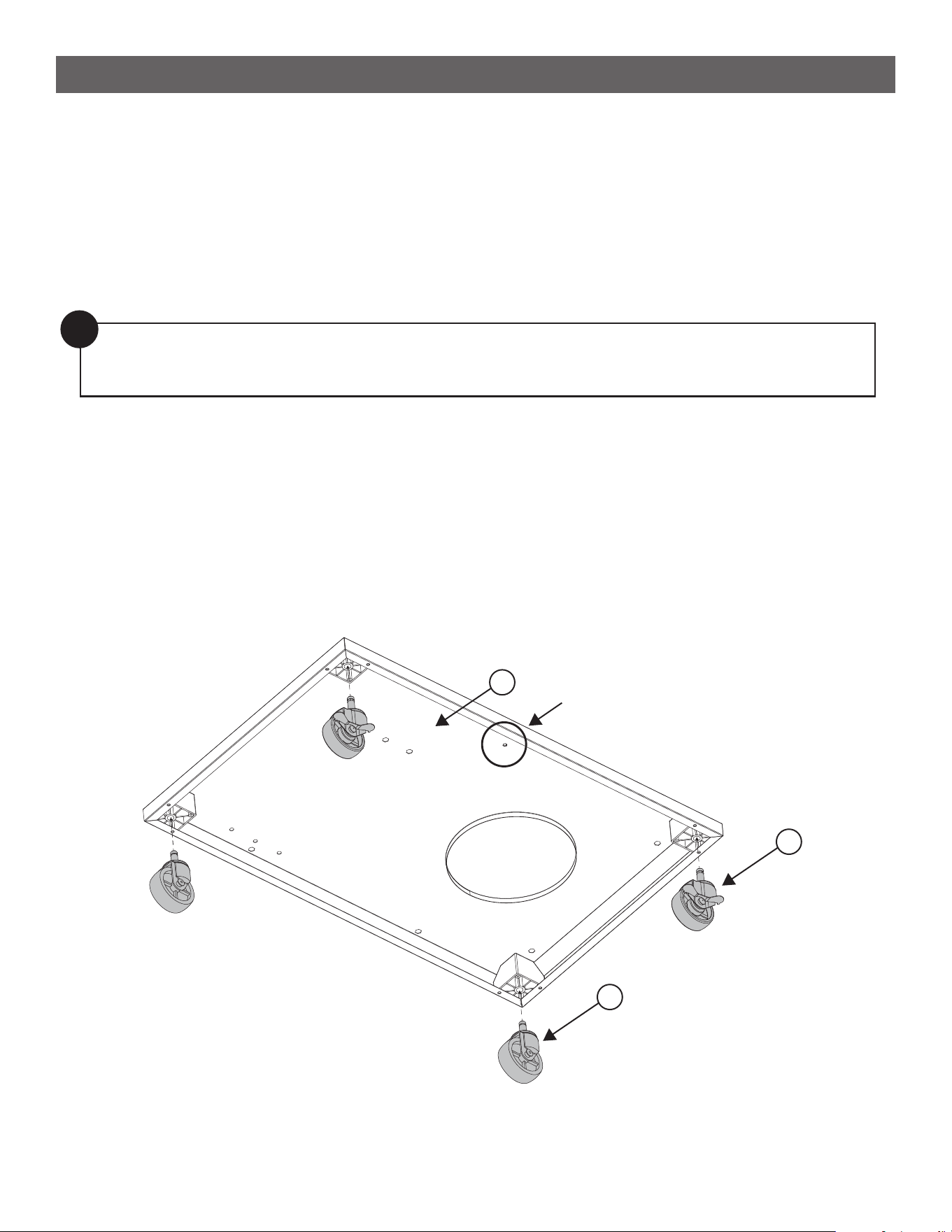
STEP 1
--------------------------------------------------------------------------------------
• Press the Locking Casters (3) into the front of the Cabinet Base (2) and the Casters (4) into the back.
• NOTE: To locate the front, look for the circled screw hole that is at the center of the front edge.
Estimated asembly time:
2 hours
Tools you will need:
• Phillips Head Screwdriver (provided)
!
Note: Step 11 requires two people to complete safely.
We recommend using our screwdriver on Step 12 & 13 for easier installation.
2
Front
3
4
7
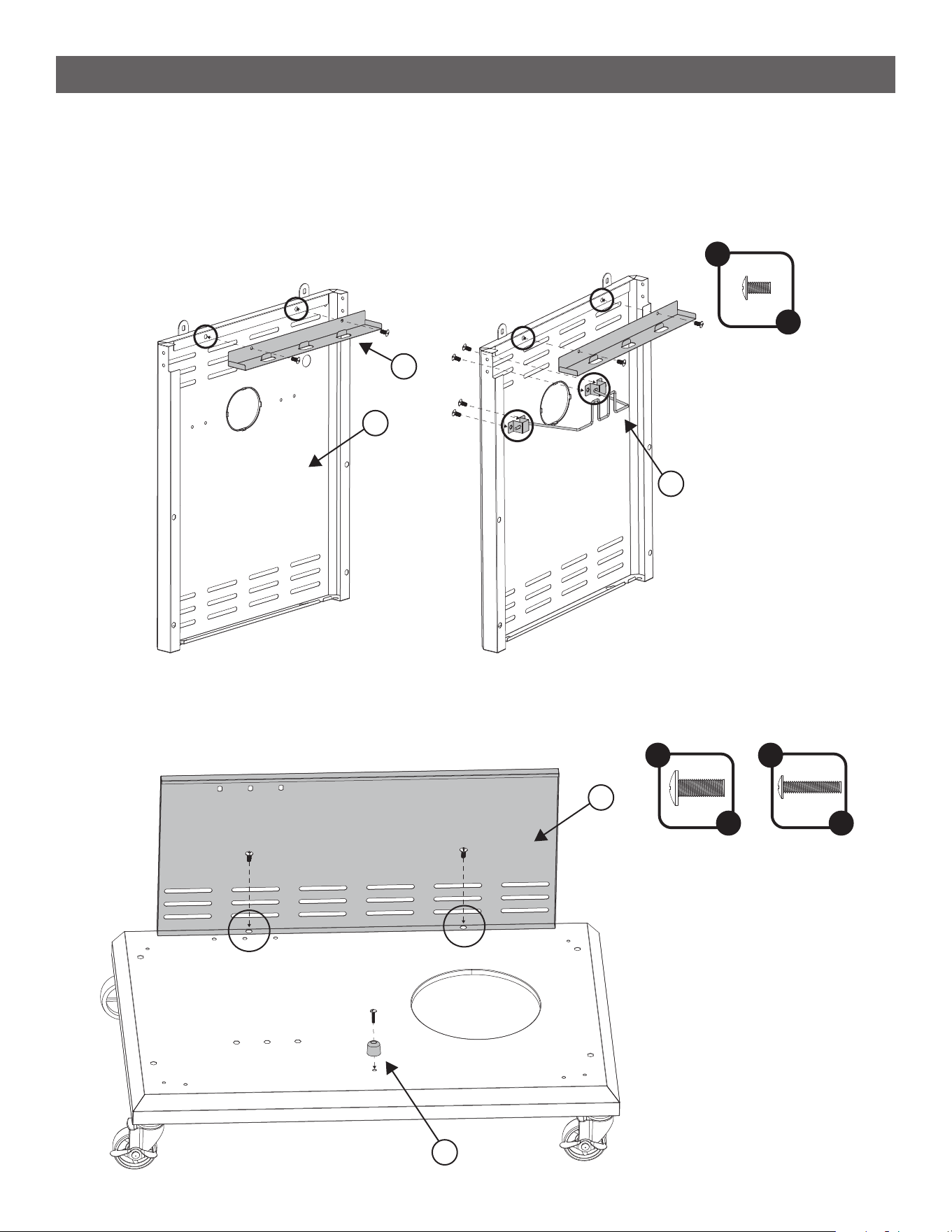
STEP 2
--------------------------------------------------------------------------------------
• Assemble the Drip Tray Brackets (5) to the Cabinet Side Panels (6) using 2 C Screws each. Do this for both
panels.
• On one of the side panels attach the Propane Tank Wire (7) using 4 C Screws.
ASSEMBLY INSTRUCTIONS
STEP 3
--------------------------------------------------------------------------------------
• Secure the Cabinet Rear Panel (8) to the Base using 2 A Screws.
• Attach the Door Bumper (9) to the front of the base using 1 D Screw.
D
x 1
8
9
A
x 2
C
x 8
6
5
7
8
ASSEMBLY INSTRUCTIONS
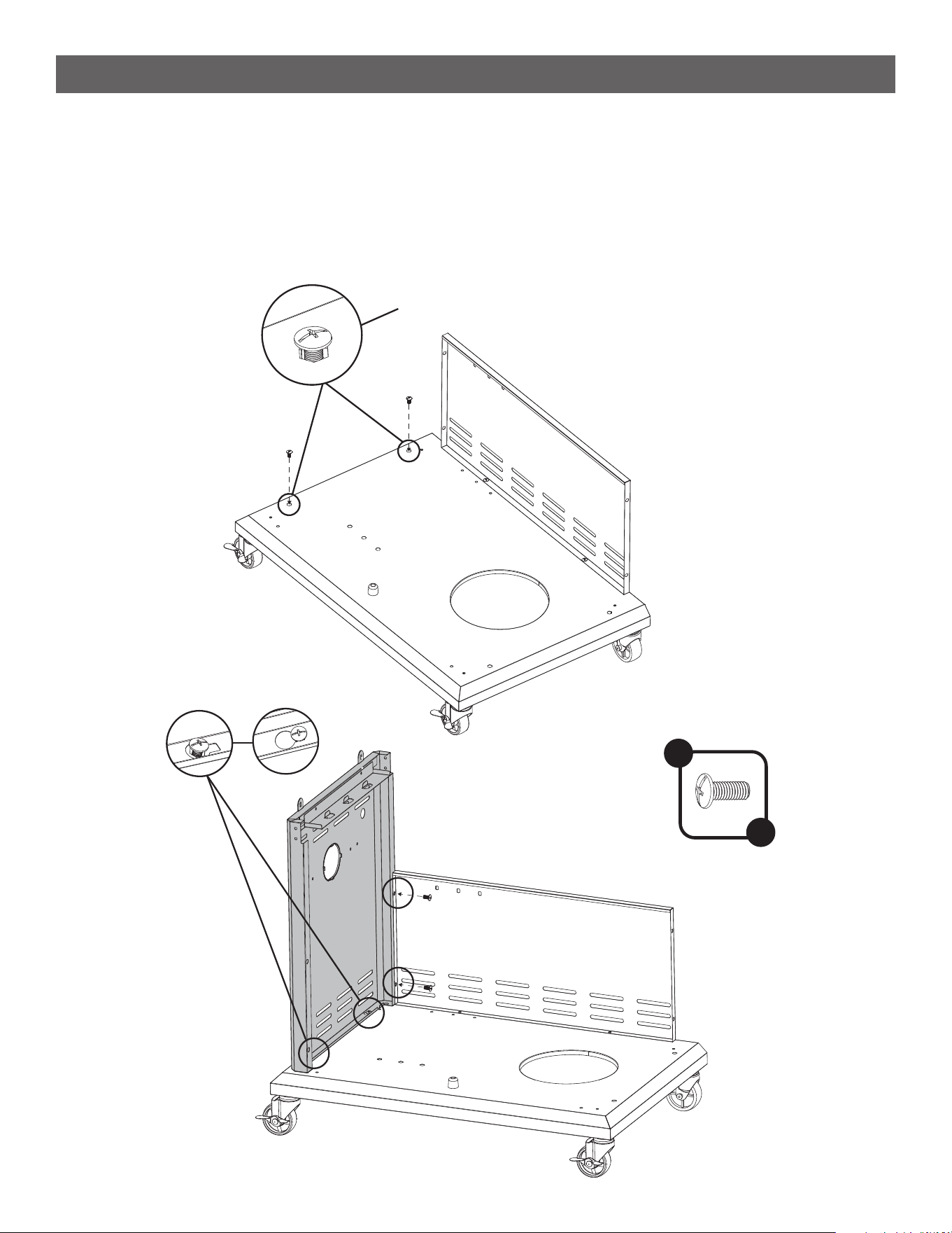
STEP 4
--------------------------------------------------------------------------------------
• Partially assemble 2 A Screws to the left of the base.
NOTE: Do not remove corner silver screw.
• Take the side panel that does not have the propane tank wire and slip the keyways underneath the screw
heads. See [ I ]
• Attach the rear panel to the side panel using 2 A Screws. See [ II ]
• Tighten the 2 loose screws to secure the side panel to the base.
A
x 4
[ I ]
[ II ]
Partially assemble
9
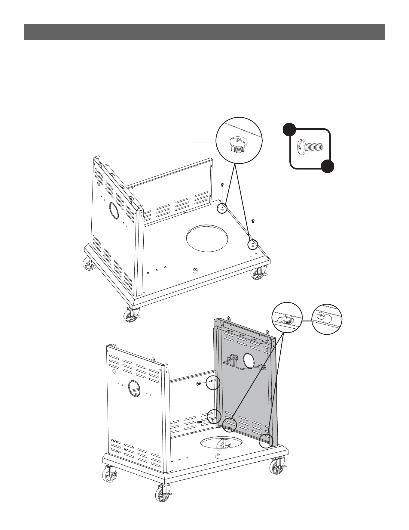
ASSEMBLY INSTRUCTIONS
STEP 5
--------------------------------------------------------------------------------------
• Repeat step 4 on the right side of the cabinet.
• NOTE: The right panel will have the propane tank wire assembled to it.
Partially assemble
A
x 4
10
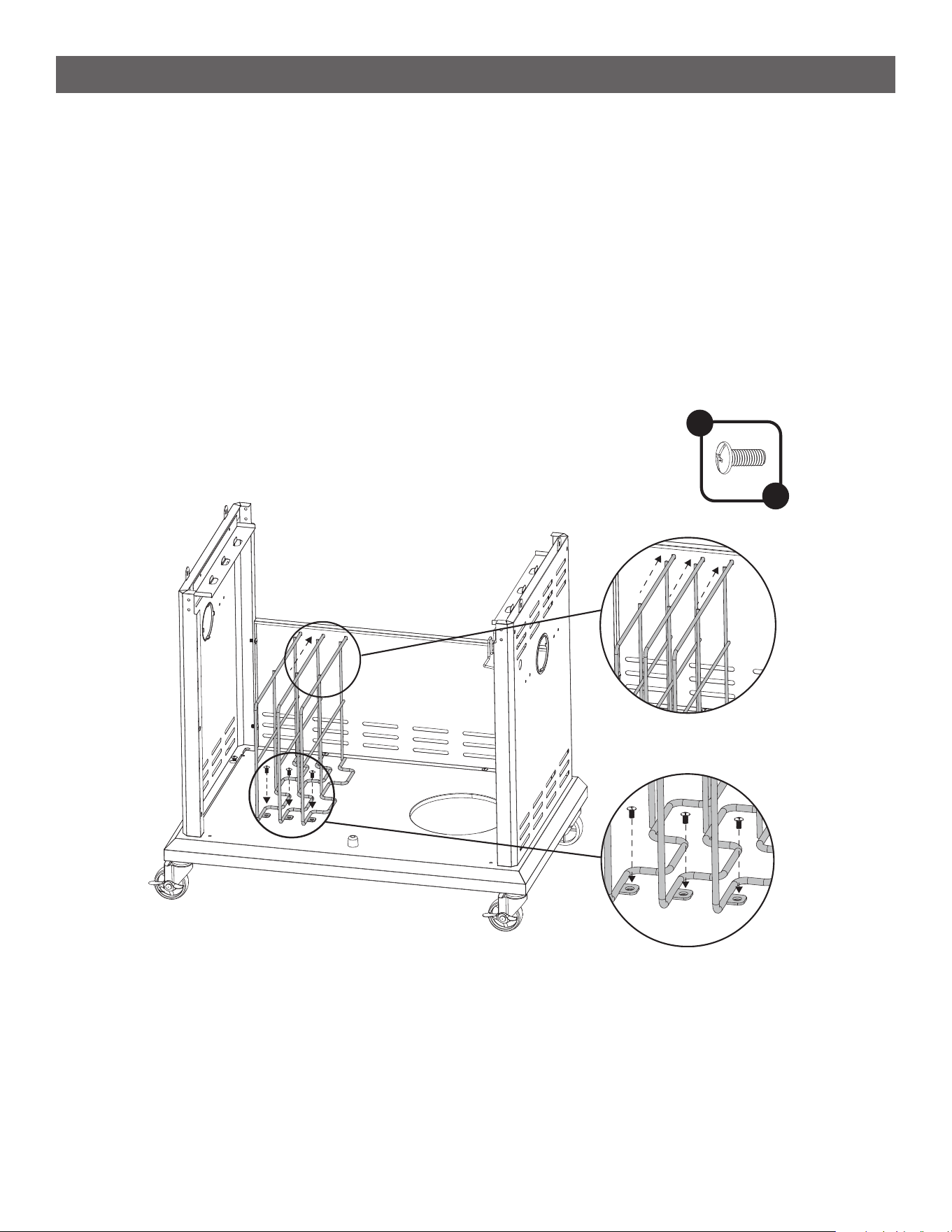
ASSEMBLY INSTRUCTIONS
STEP 6
--------------------------------------------------------------------------------------
• Install the three Accessory Racks (10) by rst inserting the longer post into the back panel, then pushing
the shorter post into the base. See [ I ]
• We recommend starting with the far left rack then middle and then far right rack.
• When both posts are in place secure the rack with 1 A Screw each. See [ II ]
A
x 3
[ I ]
[ II ]
11
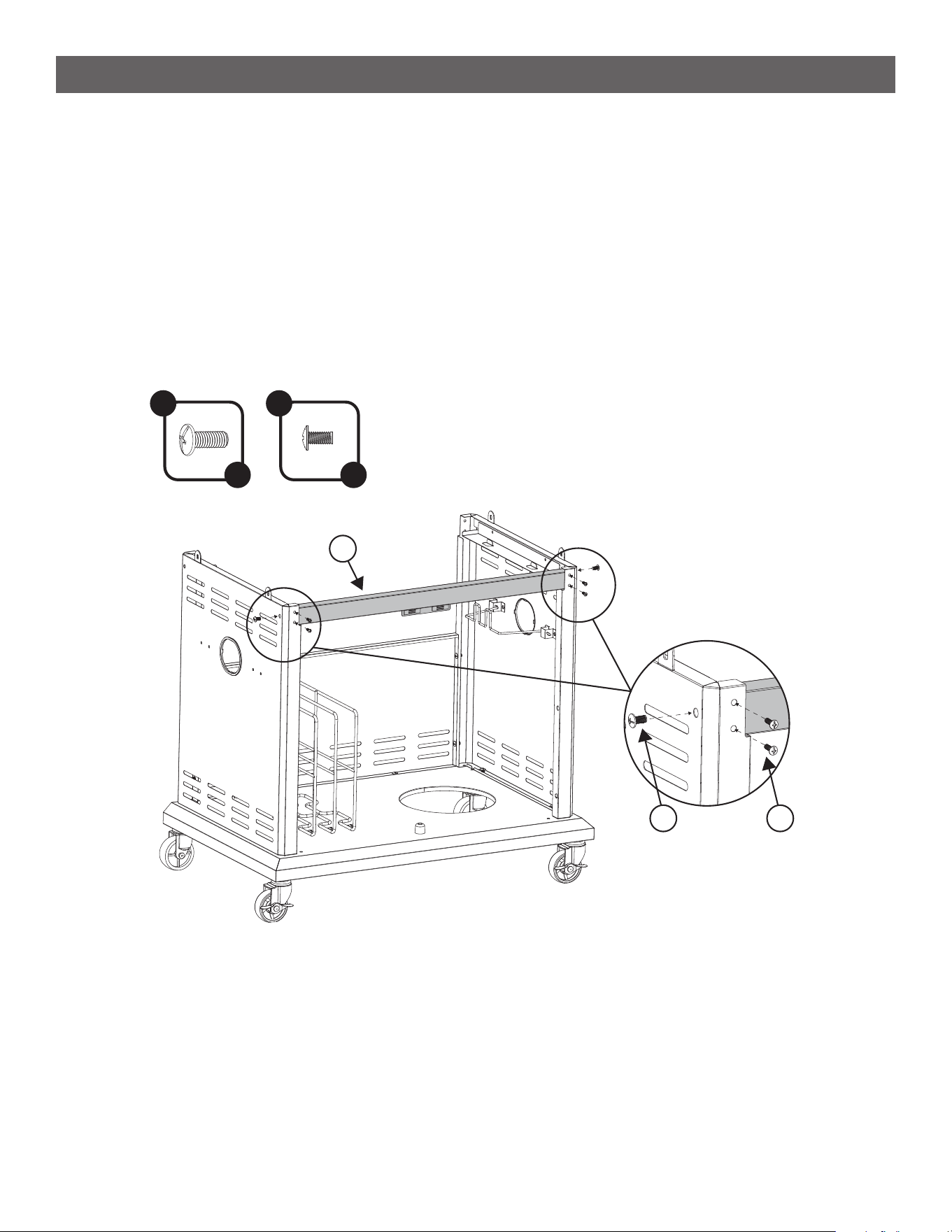
ASSEMBLY INSTRUCTIONS
STEP 7
--------------------------------------------------------------------------------------
• Secure the Cabinet Front Beam (11) to the left and right panels by rst tightening 1 A Screw per side, then
2 C Screws per side in the front.
A
x 2
C
x 4
11
CA
12
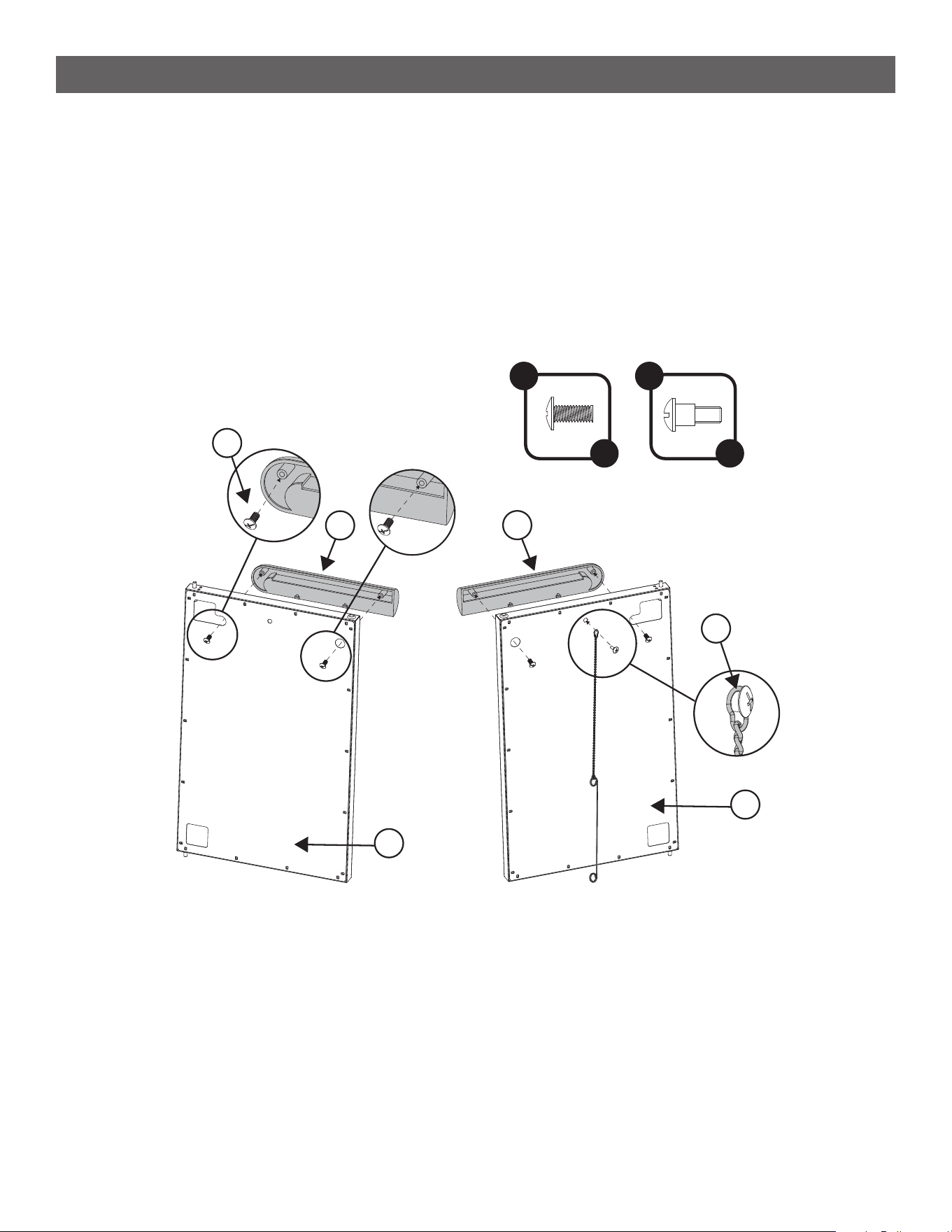
ASSEMBLY INSTRUCTIONS
STEP 8
--------------------------------------------------------------------------------------
• Assemble the Right Door Handle (14) to the Right Door (12).
• Assemble the Left Door Handle (15) to the Left Door (13).
• Attach the Match Lighter (16) to the left door by securing the ring at the end of the chain with the 1 E
Shoulder Bolt. Hook the loop of the wire onto this shoulder bolt for storage.
• NOTE: Use the diagram to ensure the correct handle is assembled to the correct door. If you accidentally
drop a screw into the door during assembly, there is a rectangular hole at the bottom corner to allow you
retrieve it.
B
x 4
E
x 1
14
12
13
15
B
E
13
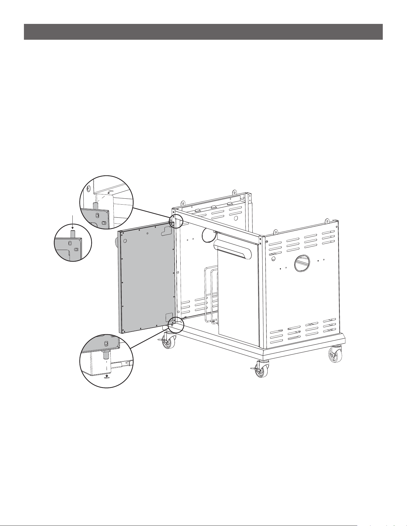
ASSEMBLY INSTRUCTIONS
STEP 9
--------------------------------------------------------------------------------------
• Install the cabinet doors (12 & 13) to the cabinet by rst inserting the post at the bottom of the door into the
corresponding hole in the base. See [ I ]
• Press the spring-loaded top post down and slide it into the corresponding hole of the front brace. See [ II ]
[ I ]
[ II ]
14
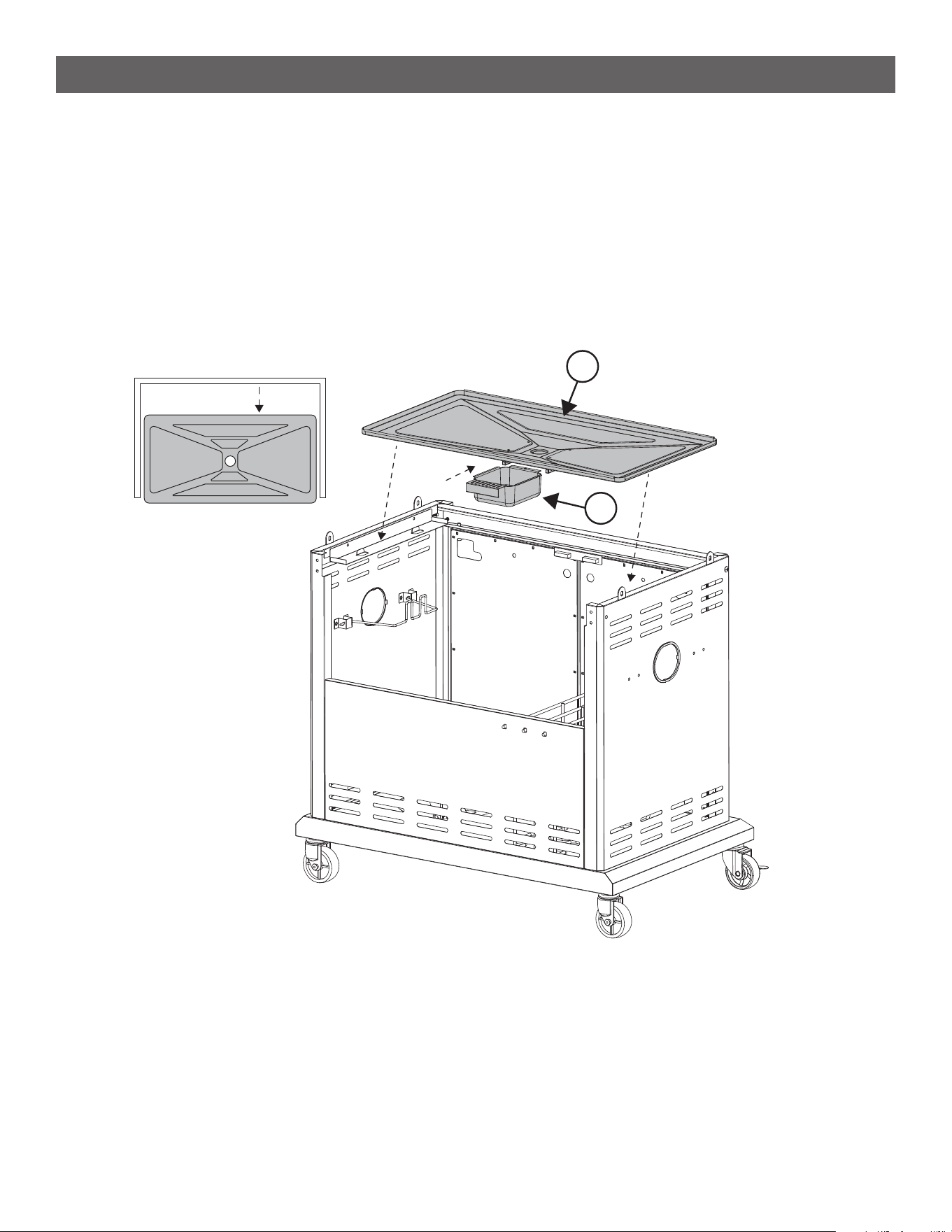
ASSEMBLY INSTRUCTIONS
STEP 10
--------------------------------------------------------------------------------------
• Place the Drip Tray (17) onto the cart resting on the drip tray brackets.
• Hang the Grease Cup (18) to the bottom of the drip tray.
• Slide drip tray towards the back 4-6 inches to allow the black battery box to hang inside the grill cabinet for
Step 11.
17
18
4-6”
Front of Grill
15
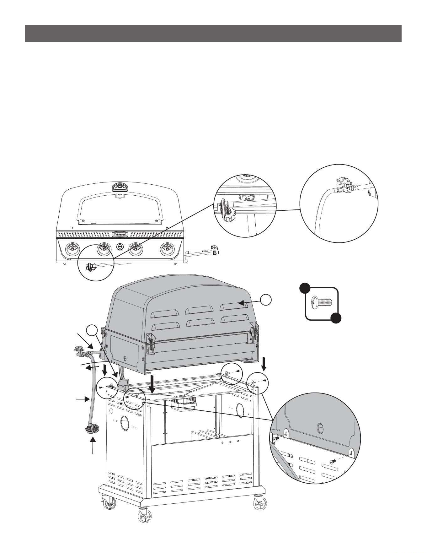
ASSEMBLY INSTRUCTIONS
STEP 11
--------------------------------------------------------------------------------------
• IMPORTANT: This step should be done by two people. Avoid crushing the gas lines/wires when placing
the burner box onto the cabinet. Hang the battery box inside the cabinet. There is a wire taped to the right
side of the grill labeled “Side Burner Ignition Wire”. Leave this wire taped where it is for now.
• NOTE: The gas line is located under the control panel and is tied to the manifold. See [ I ].
• Untwist all the wire-ties (DO NOT CUT WIRE-TIES) and unfold the regulator. Take the black rubber hose
out and route the metal gas wire through the cut-out notch right side of the burner body. Leave battery box
and rest of wires inside of grill cabinet. See [ II ].
• With the gas line held securely in the slot, place the Grill Body (1) on top of the cart. See [ III ].
• Install the 4 A Screws to secure the grill body to the cabinet. See [ IV ].
A
x 4
1
30
[ III ]
[ I ]
[ II ]
[ IV ]
Gas
Line
Rubber
Hose
Regulator
16
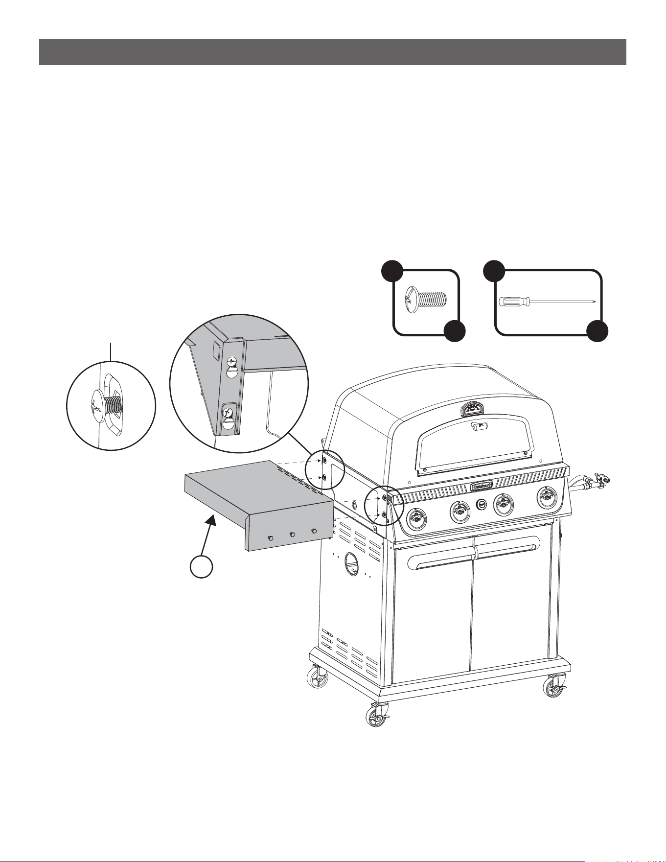
ASSEMBLY INSTRUCTIONS
STEP 12
--------------------------------------------------------------------------------------
• Partially assemble 4 A Screws to the left side of the grill body.
• Using the keyhole slots, hang the Left Side Table (19) onto the grill by these 4 loose screws. When all 4
screws are in their corresponding slots, tighten them to secure the side table.
• NOTE: Use provided 11” screwdriver G for easy installation.
Partially assemble
A
x 4
G
x 1
19
17
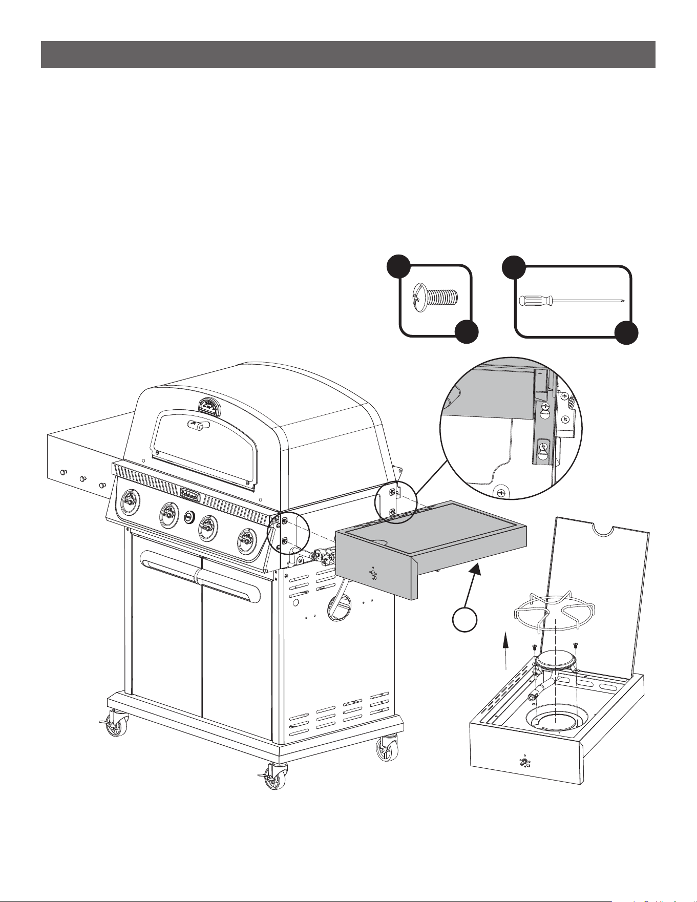
ASSEMBLY INSTRUCTIONS
STEP 13
--------------------------------------------------------------------------------------
• Remove the pot rack and burner from the Right Side Table (20). Save these parts for later. See [ I ]
• Partially assemble 4 A Screws on the right side of the grill.
• Using the keyhole slots, hang the right side table onto the grill by these 4 loose screws. When all 4 screws
are in their corresponding slots, tighten them to secure the side table. Access to some of these screws
may be tight and the screwdriver will need to be angled. It is recommended to go slowly to avoid damaging
the screws.
• NOTE: Use provided 11” screwdriver G for easy installation.
A
x 4
[ I ]
20
G
x 1
18
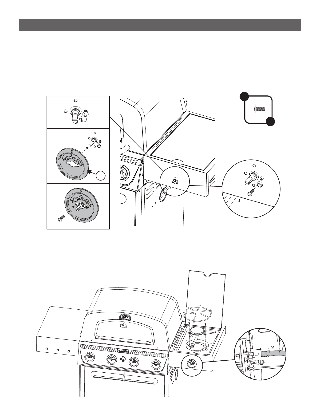
ASSEMBLY INSTRUCTIONS
STEP 15
--------------------------------------------------------------------------------------
• Insert the burner tube over the brass nut with a pin hole at the back of the valve and reattach the burner to
the side table. See [ I ]
• Reinstall the burner rack by placing the 3 longer legs into the 3 open holes.
STEP 14
--------------------------------------------------------------------------------------
• Position the valve assembly with the ‘D-shaped’ knob stem in the control panel line up the screw holes.
Thread on C Screw through the front face of the side table into the valve. Do not tighten. See [ I ]
• Maneuver the Bezel (21) under the screw head so that the red dot is at the top. See [ II ]
• Thread the second C Screw so that it secures both the valve and the bezel. Ensuring the bezel is as
centered as possible with the valve stem, tighten both screws, being careful not to damage the bezel.
See [ III ]
[ I ]
[ I ]
[ II ]
[ III ]
21
C
x 2
19
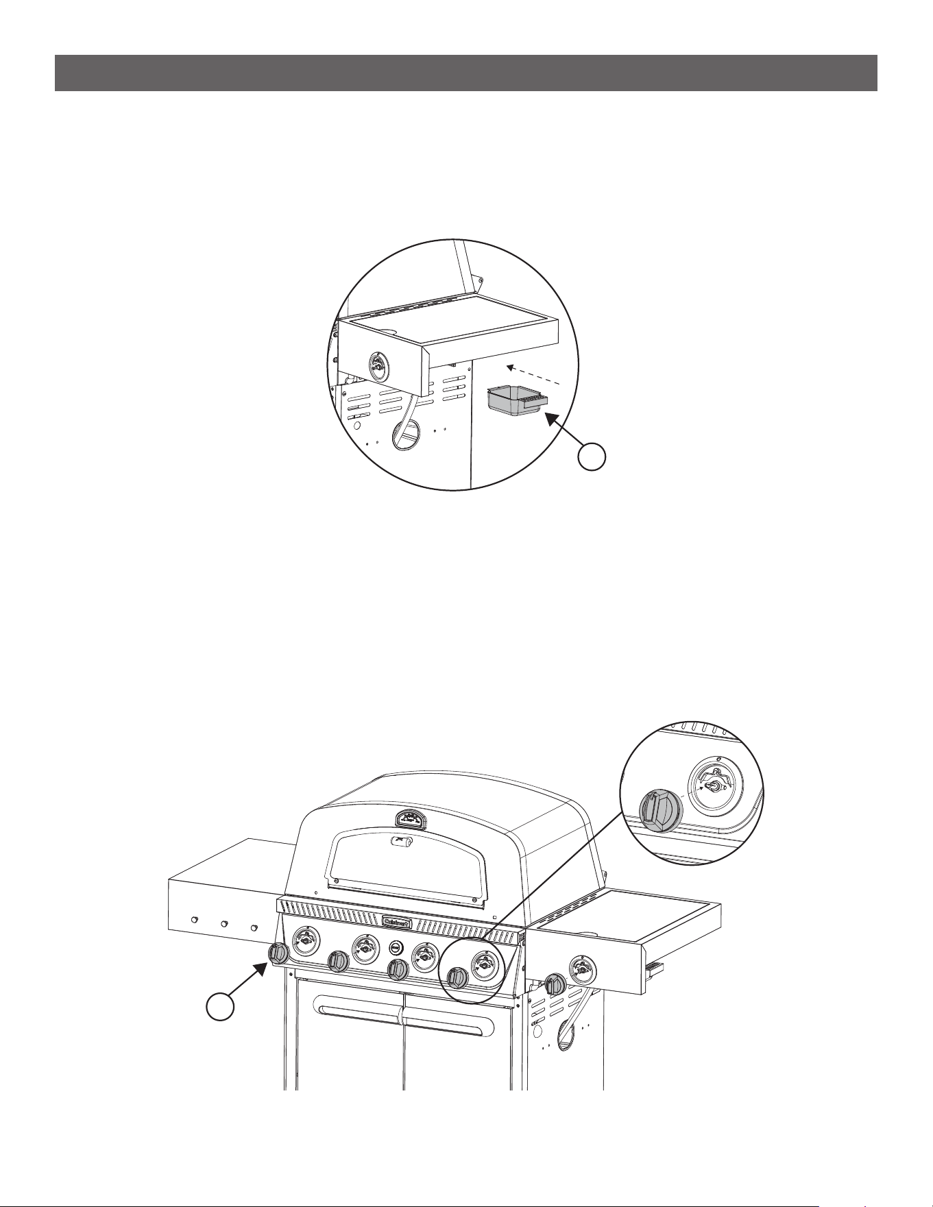
STEP 16
--------------------------------------------------------------------------------------
• Install the Grease Cup (18) for the side table.
ASSEMBLY INSTRUCTIONS
STEP 17
--------------------------------------------------------------------------------------
• Press the Knobs (22) onto the valve stems.
NOTE: the ‘D-shaped’ stem inserts into a corresponding ‘D-shaped’ hole in the knob. When installed make
sure the red indicator on the knobs are pointing up.
18
22
20
F
x 1
[ I ]
[ II ]
A
x 2
23
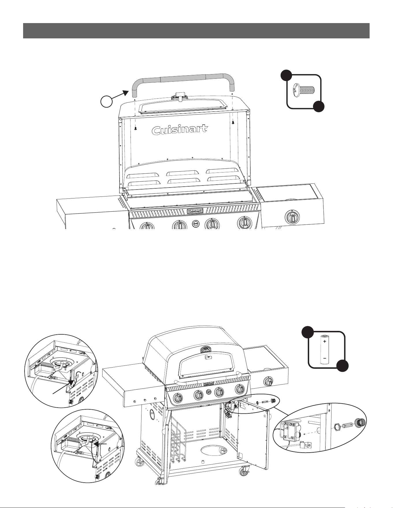
ASSEMBLY INSTRUCTIONS
STEP 18
--------------------------------------------------------------------------------------
• Install the Lid Handle (23) using 2 A Screws.
STEP 19
--------------------------------------------------------------------------------------
• Unscrew the battery cap and plastic nut from the battery box hanging from the grill body in the cabinet
below.
• Push the threaded section through the hole on the right-side panel of the cabinet and secure it with the
plastic nut from the outside.
• Place the AA Battery (F) into the battery box with the ‘+’ facing out, and replace the battery cap. Take the
Side Burner Ignition Wire taped to the grill body [ I ] and plug it into the white cap [ II ] that us underneath
the burner table for a positive connection.
• Verify it is installed properly by holding down the START button, as you should hear a clicking sound.
21
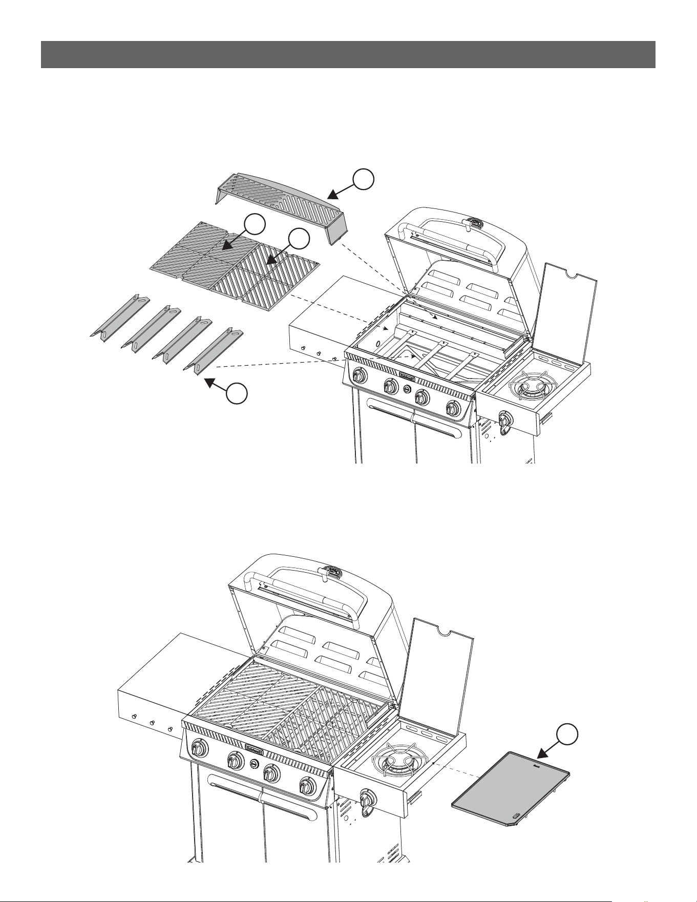
STEP 20
--------------------------------------------------------------------------------------
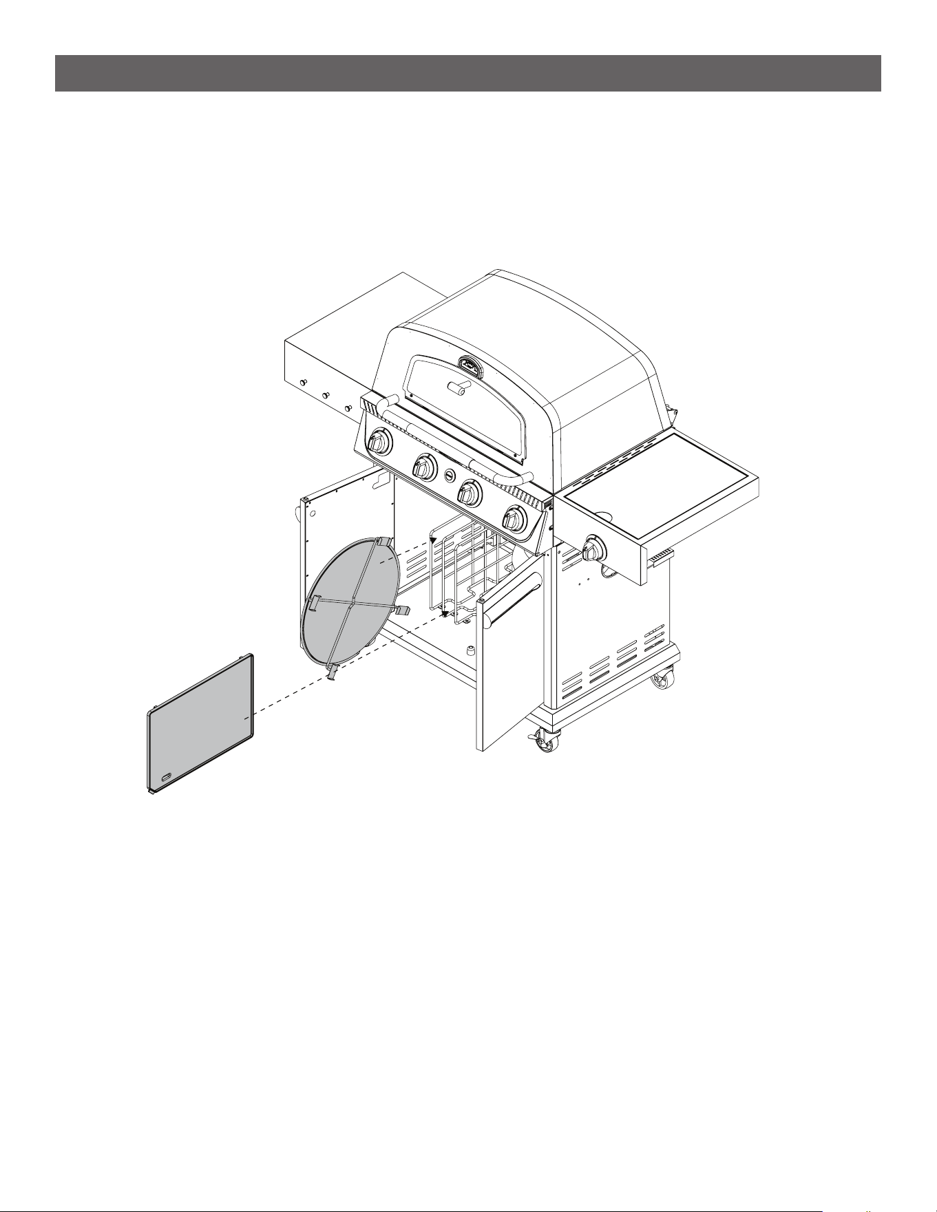
• Place the Flame Tamers (24) over the 4 burners. See [ I ]
• Place the Grill Grate Left (25) and Grill Grate Right (26) into the re box. See [ II ]
• Place the Warming Rack (27) on top. There are notches that the warming rack slots into. See [ III ]
[ I ]
[ II ]
[ III ]
27
24
25
26
ASSEMBLY INSTRUCTIONS
30
STEP 21
--------------------------------------------------------------------------------------
• Place the Griddle Plate (30) over the top of the side burner with the grease drain hole and notch facing the
bottom right corner. Ensure the grease drain hole of the griddle plate is over the grease cup.
NOTE: Insert back legs rst.
• When using the side burner with a pan or pot, the griddle plate can be stored in the cabinet below.
22
ASSEMBLY INSTRUCTIONS
STEP 22
--------------------------------------------------------------------------------------
• When the Pizza Stone Holder or Griddle Plate are not in use, you can store them using the rack in the
lower cabinet. Insert the Pizza Stone Holder on the far left side, then the Pizza Stone in the middle, then the
Griddle Plate on the right slot. You can also store the folded Warming Rack inside the cabinets too.
23
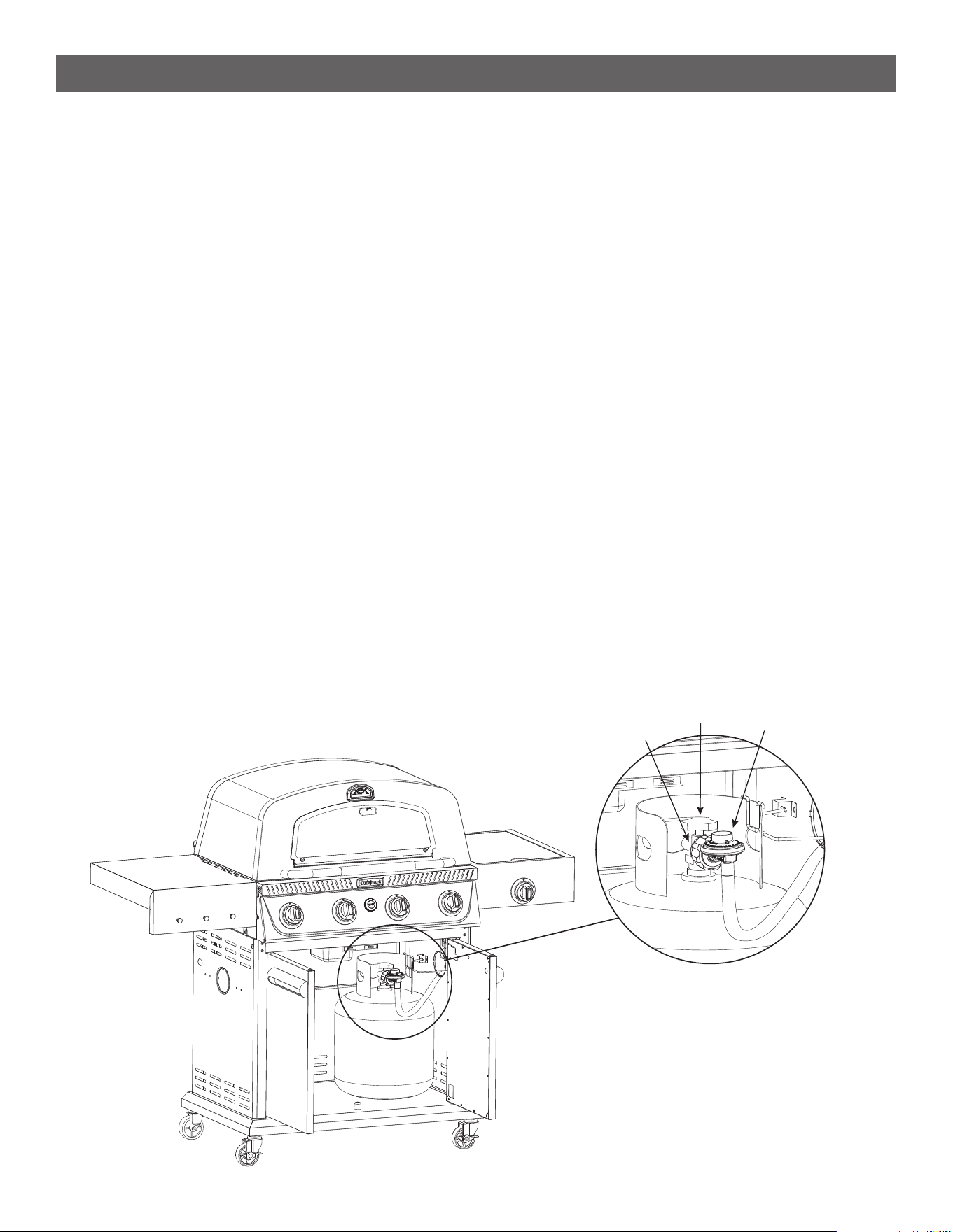
SETUP INSTRUCTIONS
CONNECTING THE LIQUID PROPANE (LP) CYLINDER
--------------------------------------------------------------------------------------
• Double check the cylinder valve to ensure it is in the “OFF” position. If not, turn the valve clockwise until it
stops.
• Conrm the cylinder valve matches the mating style of the regulator.
• Make sure the burner valve is in the “OFF” position. If not, push the knob in and turn it clockwise until the
words “OFF” is displayed on the top of the knob.
• Inspect the valve connections, port and regulator assembly to ensure there is no debris or damage.
• Thoroughly inspect the gas hose for any debris or damage like cracks, abrasion, or cuts before each use.
Clean the hose if it is dirty. Do not use the product if the hose is damaged, contact Cuisinart customer
service to get a replacement.
• Place the LP cylinder in the lower cabinet so the ring at the bottom of the cylinder sits inside the hole of the
base.
• Flip the tank retention clip down so that it clips onto the upper collar of the LP cylinder. The LP cylinder
should be secured in a perfectly upright position.
• Thread the plastic nut of the regulator onto the valve of the LP cylinder by hand. Do not use tools because
they can damage the components, resulting in a dangerous gas leak.
• Before lighting the grill conduct a leak test, detailed in a later section.
DISCONNECTING THE LIQUID PROPANE (LP) CYLINDER
--------------------------------------------------------------------------------------
• Press in and then turn the burner valve clockwise to “OFF”, then wait until all surfaces are cool.
• Close the LP cylinder valve by turning it clockwise until it stops.
• Detach the LP cylinder from the regulator by turning the regulator nut counter clockwise until it comes off.
• Place dust cap on LP cylinder valve outlet whenever the cylinder is not in use. Only install the type of dust
cap on the LP cylinder valve outlet that is provided with the cylinder valve. Other types of caps or plugs
may result in leakage of propane.
Cylinder
Valve
Nut
Regulator
24
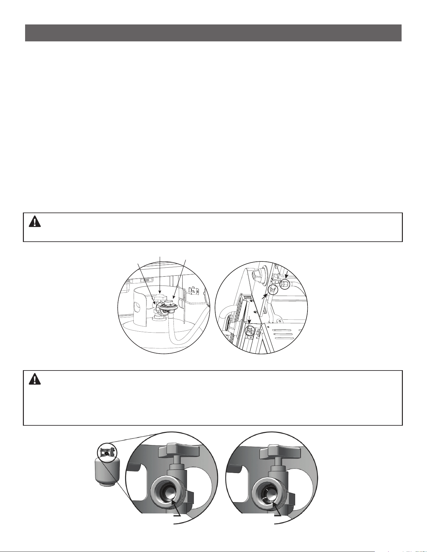
Example of a good
rubber seal.
Example of a damaged
rubber seal.
SETUP INSTRUCTIONS
LEAK TEST PROCEDURE
--------------------------------------------------------------------------------------
Although gas connections on the Grill are leak tested prior to shipment, we recommend conducting a leak test
after initial setup and every time an LP cylinder is attached. In addition, we recommend performing a leak test
once a year. If the unexpected smell of gas is detected at any time a full leak test should be performed.
1. Create a solution of 80% water and 20% liquid soap in a spray bottle.
2. Connect the LP cylinder to the product by following the steps in the earlier section
“CONNECTING THE LP CYLINDER”.
3. Turn the LP cylinder valve counterclockwise to open the valve.
4. Apply soap to all gas ttings focusing on the connection points at the LP Cylinder and the control valve.
Recommended locations to check are circled in the illustration. Soap bubbles will expand if there is a leak.
5. If a leak is discovered, immediately turn the gas supply off and tighten any loose ttings.
6. Turn the gas back on and recheck.
7. If the leak continues, turn off all gas and disconnect the LP cylinder. Contact our customer service team for
further assistance at +1 866-994-6390 or email [email protected].
WARNING: Check all gas supply ttings for leaks regularly. Do not use the Grill until all connections have
been checked and do not leak. Do not smoke while leak testing. Never leak test with an open ame.
WARNING: The rubber seal on your propane tank valve may, over time, show marked and visible damage
or deterioration. If the seal has deteriorated a leak may occur even if the connection is tightened fully. Visual
inspection of the seal must be conducted every time a LP gas cylinder is attached to the grill. If your LP gas
cylinder shows signs of seal damage, including visible cracks, or pitting, you must return it to the propane tank
supplier.
LP Cylinder Valve Connections
Cylinder
Valve
Nut
Regulator
25
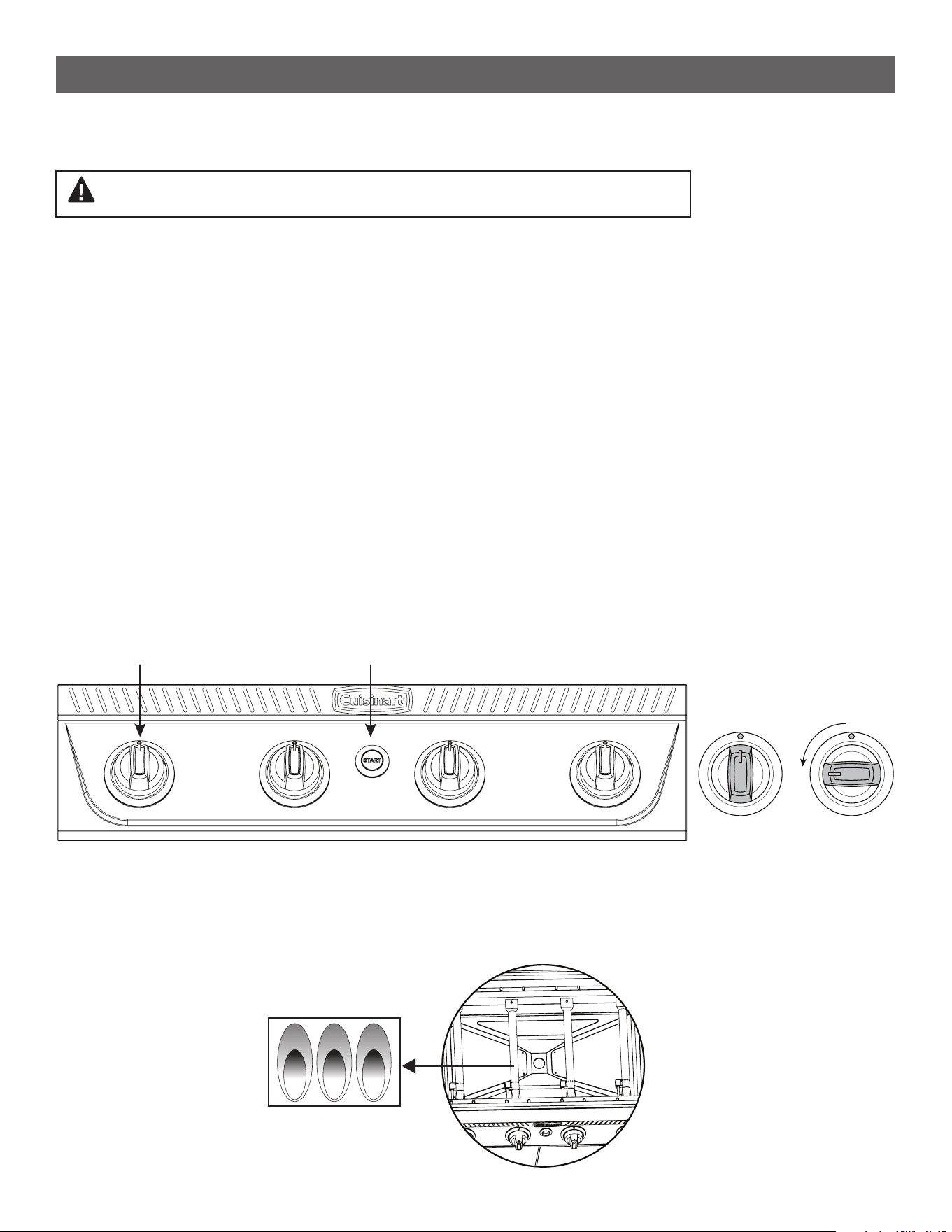
OPERATING INSTRUCTIONS
OUTDOOR USE ONLY / NEVER LEAVE UNATTENDED
--------------------------------------------------------------------------------------
1. Make sure the LP cylinder is tightly threaded into the regulator (hand tighten only). Also check that the burner
knob is in the “OFF” position.
2. Open the lid.
3. Open the bottom cabinet door then slowly turn the LP cylinder valve counterclockwise to open it. It is
important to open the rst half turn slowly to ensure safety shut off mechanisms are not triggered in the
regulator. After the rst half turn it is ok to open it the rest of the way at normal ow.
4. Press the burner dial in and turn knob counterclockwise until HIGH is displayed.
5. Immediately press and hold in the ignition START button until the burner has ignited, then release START
button.
6. If ignition does not occur in 3-5 seconds, turn the burner knob off. Wait 5 minutes before attempting to re-light
the grill. If multiple attempts fail to ignite the burner call our customer service team at +1 866-994-6390 for
assistance.
7. This process can be used to turn on any combination of burners, or all of them at once.
8. To turn the appliance off rotate all burner knobs clockwise until the red indicator is pointing straight up, 12:00.
Visually inspect the burners to ensure there are no ames.
9. Close the LP cylinder valve by turning it clockwise until it stops.
WARNING: DO NOT stand with any body parts over active burner.
FLAME CHARACTERISTICS
• Visually check ames on the burner to ensure the gas is combusting effectively. Flames should be blue with a
lighter blue cone in the center. The ames should be in contact with the burner and all burner ports should be
lit. Some orange at the tips is OK but if more than half the ame is orange and appears lazy, there could be an
obstruction with the air supply.
Burner Knobs Start Button
OFF
HIGH / START
26
OPERATING INSTRUCTIONS
USING THE GRILL
--------------------------------------------------------------------------------------
1. Turn on as needed 1, 2, 3 or all 4 grill knobs to HIGH, wait 3-5 seconds and push in the START button.
2. Allow the grill to warm up with the lid closed for 5-10 minutes prior to cooking.
3. You may cook on the grill in any weather. If the temperature is extremely cold or hot, the cooking times will be
slightly increased or decreased. Keep the grill out of excessive winds when operating.
USING THE GRIDDLE
--------------------------------------------------------------------------------------
1. Position the griddle plate into place with drain hole in the front right side. NOTE: Drain hole should be over the
notch.
2. Turn on the side griddle knob to HIGH, wait 3-5 seconds and push in the START button.
3. Preheat griddle on high setting for 10 minutes, then adjust heat to the desired temperature.
Note: Never use the griddle with the side table lid closed. The lid will get dangerously hot, discolor, and it may
affect clean combustion.
HOW TO SEASON YOUR GRIDDLE
--------------------------------------------------------------------------------------
In this process you’ll be using high heat to bond the oil to the surface. Using a paper towel, rub a thin coat of
oil on the entire surface of the griddle. Then turn your side burner griddle on high. The oil will eventually begin to
smoke which is good. Leave it on high until the smoke stops. That means you passed the smoke point. Finally,
you’ll want to cool the surface and repeat the process above 2-3 times until you get a smooth black surface on
the griddle. If the griddle surface is hot you can use tongs or other protective gear to protect your hands while
oiling. Once you’ve completed this process you’ll have the perfect griddling surface to get cooking on.
29
28
[ I ]
[ II ]
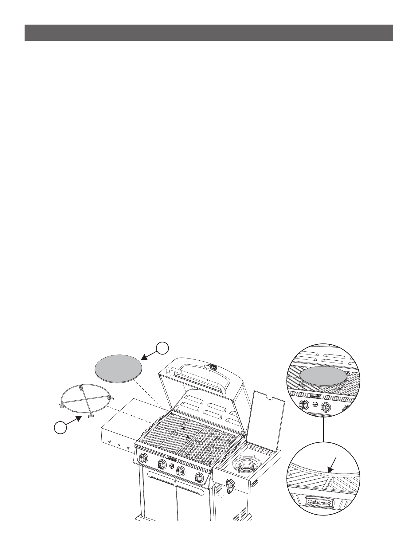
USING THE PIZZA OVEN
--------------------------------------------------------------------------------------
• Place the Pizza Stone Holder (28) onto the middle of the cooking grates. There is a downward facing indent
in the pizza stone holder ring, this should point towards the front of the grill. See [ I ]
• Place the Pizza Stone (29) into the rack. See [ II ]
• When not in use the pizza accessory can be stored in the cabinet below.
27
USING THE PIZZA OVEN
--------------------------------------------------------------------------------------
• Insert the black Pizza Stone Holder and Pizza Stone together with the indented wire facing the front of the grill.
The riser peg feet should be evenly spaced front to back and side by side so that rack is approx. 1” or so from
the front grill. Check the position by closing the lid slowly and close without interference. If needed, adjust the
pizza rack location centered in middle.
• The riser pegs will secure the pizza rack & stone in place for cooking. Smooth stone surface facing upwards.
• Shut the lid, close the Glass pizza door, and preheat the stone on high for 10-15 minutes based on outside
temperature adjust accordingly.
• Before placing your pizza in, turn the (4) control knobs from HIGH, down 2 clicks lower which is the optimum
“PIZZA COOK” setting on the dials, (650 F° to 675 F°). Adjust knobs higher or lower when cooking in colder or
hotter conditions to keep the 650° to 675° F range.
• Open the front pizza glass door by turning T-shaped knob to the left and use a pizza peel to place the pizza
into the oven and center it on the stone.
Note: Dust your pizza peel with our or cornmeal to prevent sticking when transferring pizzas to and from the
stone. Helps roll your dough easy.
• Keep Glass pizza door and lid closed while pizza is cooking.
• Cook for 5-7 minutes or until desired doneness is reached.
• Turn your pizza once 180 degrees half way through cook time (at 2-3 minutes) to ensure even cooking
Note: We recommend to wait for the Grill & Pizza Stone & Rack unit to cool down enough before
switching out to Grill grate only cooking surfaces.
!
OPERATING INSTRUCTIONS
HOW TO USE YOUR PIZZA STONE
--------------------------------------------------------------------------------------
1. Pre-heat your stone on your grill or oven to 600° F for about 10-15 minutes.
2. Dust your pizza peel with our or cornmeal to prevent sticking when transferring your pizza to the stone.
3. Let your pizza cook for 3-4 minutes, turn it 180 degrees once to ensure even cooking. Finish in 3 to 4 minutes
more and pull the pizza out and check crust and toppings, insert for 30-45 seconds more only if needed.
4. Once the crust is brown and your toppings are cooked, remove your pizza and enjoy!
What Not to Use on Your Pizza Stone :
Water should be the only moisture that your stone is exposed to. Do not use any soap, cleaning chemicals, or oils
on your pizza stone. The pizza stone is made from cordierite stone which is a very porous material. It will absorb
liquids that are applied to it and will damage your stone over time. If you allow your stone to get too wet it will not
produce a crispy pizza crust. Liquids that are absorbed into your stone will affect the taste of your pizza as well.
Liquids that are absorbed into your stone will affect the taste of your pizza as well. When heating your stone for
the rst time you may experience an odor coming from the stone. This smell is from the cordierite and is non-
toxic. To help rid your stone of this smell, before the rst use, heat your stone in your kitchen oven for 30 minutes
at 400+ degrees F. Keep windows and doors open for this process. On second use, most of the smell will have
dissipated.
28
CLEANING AND CARE
--------------------------------------------------------------------------------------
General Grill Cleaning
• Wash with mild detergent or a non-abrasive cleaner and warm water.
• All surfaces can be cleaned with a non-abrasive sponge or rag and mild detergent with warm water to soften
any build-up. For best results wipe grill dry completely with an absorbent towel after to remove all moisture
from all surfaces, especially on stainless-steel areas.
• Be careful not to damage painted surfaces, as it will expose the steel underneath to moisture which can result
in corrosion like rust. It is recommended to cover that open area with matching color paint.
• To help avoid corrosion like rust or weathering of painted surfaces, it is recommended to use a waterproof-
vented grill cover to store the grill when not in use.
Grill Glass Cleaning
To clean the grill’s glass window, rst remember to clean regularly so it does not allow for too much build-up of
smoky or greasy residue:
*Use grease cleaning soap like Dawn – or a glass cleaner soap and spray or mix with warm water onto a towel/
cloth as it is mild enough and decreases to lift off dirt and smoke lm. Finish with clean water and towel dry before
heating.
Grease Pan and Cup:
The grill grease drip tray and side griddle cup should be kept clean on a regular basis to prevent heavy buildup of
debris. Accumulated grease is a re hazard.
Griddle Plate Cleaning and Care:
Griddles are remarkably easy to keep clean. After you’ve completed your rst cook you’ll want to spray down
the hot surface with water and scrape debris away. The steam from the water on the hot surface will help release
tough debris. Scrape the residue down into the grease trap. Turn the griddle off and let the surface cool. While it
cools you’ll want to remove and clean out the grease trap. Doing this each time will ensure you have no spill over
the next time. When the surface is cool, apply a thin layer of oil over the surface to maintain your seasoning. Then
you’ll want to store in a cool, dry place. If you’re storing outside cover the griddle to prevent water collecting on
the surface. Even if your surface does start to rust all hope is not lost. Griddles are very resilient and with a little
work you can get it back to new. Simply use a steel scouring pad to remove all rust from the surface. Then go
through the seasoning steps again. This will recondition the griddle and you’ll be back to cooking again in no time.
How to Clean Your Pizza Stone :
1. Let the stone cool completely before attempting to clean.
2. Scrub the pizza stone thoroughly with a stone brush.
(We recommend the Cuisinart Outdoors CCB-4114 or CCB-399 pizza stone brushs)
3. If needed, use a damp wash cloth with hot water to help break up any burnt-on debris before brushing again.
4. If using water, let the stone air dry or dry it with a clean towel.
CARE AND MAINTENANCE
Note: DO NOT leave the grill outside during inclement weather unless it is covered. Rain water can
collect inside of the grill, the grill body or the grease cups if left uncovered.
!
Note: Water will help to loosen debris on the stone, but is not necessary if you can remove debris with
the brush rst. The less water you use on your stone the better and it will last longer.
!

29
COVER YOUR GRILL
--------------------------------------------------------------------------------------
Your new Propel+ grill should be covered to help keep the elements out when not in use. We recommend a cover
designed specically for this grill size for best results. Always towel dry a cold wet grill before covering.
GRILLING FOODS TO THE PROPER TEMPERATURE
--------------------------------------------------------------------------------------
Grilling foods to the proper temperature:
• Use a meat thermometer to be sure food has reached a safe internal temperature.
• The USDA recommends the minimum temperature be reached for the following food items:
Chops . . . . . . . . . . . . . . . . . . . 145° F (62.8° C)
Ground Meat . . . . . . . . . . . . . . 160° F (71° C)
Pork . . . . . . . . . . . . . . . . . . . . . 145° F (62.8° C)
Poultry . . . . . . . . . . . . . . . . . . . 165° F (73.9° C)
Roasts . . . . . . . . . . . . . . . . . . . 145° F (62.8° C)
Seafood . . . . . . . . . . . . . . . . . . 145° F (62.8° C)
Vegetables . . . . . . . . . . . . . . . . 145° F (62.8° C)
MANAGING FLARE-UPS AND GREASE FIRES
--------------------------------------------------------------------------------------
*Flare-ups are common when cooking meat on a gas grill, contributing to the distinct taste of grilled food.
However, it’s important to handle them carefully, as they can lead to overcooking and pose risks to both you and
your grill. Opening the grill lid should be done cautiously, as sudden are-ups may occur. These are-ups are often
caused by grease build-up, which can lead to dangerous situations.
• If a grease re ignites, never pour water on the ames. Water can cause grease to splatter, leading to burns or
other serious injuries.
• For a grease re with the lid open: Keep the lid open, turn off the burner knobs, and shut off the LP cylinder
valve. If safe, move the food to another part of the grill and allow the re to burn out, or extinguish the ames
with baking soda.
• For a grease re with the lid closed: Keep the lid shut, as opening it could increase the ames. Turn off the
burner knobs and the LP cylinder valve, then let the grease burn itself out.
• In either case, never use water to extinguish a grease re, as it can cause the re to spread.
• If the re doesn’t quickly subside or appears to be growing, use a Type BC dry chemical re extinguisher, or
smother the ames with sand, dirt, or baking soda. It’s important to note that closing the lid alone won’t put
out a grease re.
Minimize Flare-Ups:
• Trim excess fat from meats prior to cooking.
• Cook meats with high fat contents (chicken or pork) on Low settings or indirectly.
• Clean grill frequently to minimize grease buildup.
Note: Any 60” x 24” x 46” cover size will t this Propel+ grill.
!
CARE AND MAINTENANCE
These Grill covers will t just right. Here are some Cusinart Outdoors options:
• CGC-60B Heavy-Duty 60” Barbecue Grill Cover - Black
• CGC-60T Heavy-Duty 60” Barbecue Grill Cover - Tan
• CGWM-040 Heavy-Duty 4-5 Burner Gas Grill Cover - Black
30
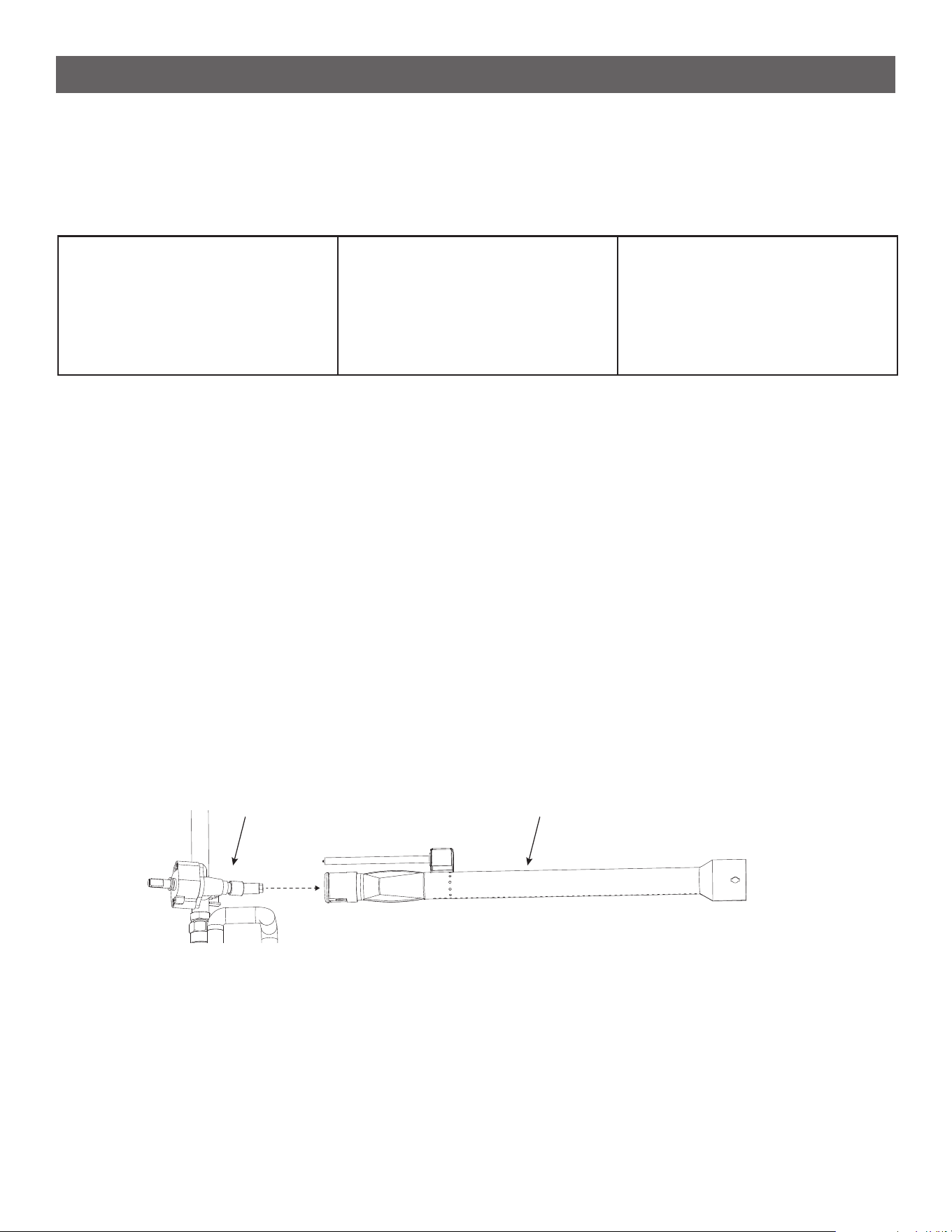
MAINTENANCE
--------------------------------------------------------------------------------------
• There is very little care and maintenance needed for this grill which is designed and made of materials that will
last for many years with normal use.
• Following these instructions will improve the longevity and quality of cooking. Keeping appliance area clear and
free from combustible materials, gasoline, and other ammable vapors and liquids; not obstructing the ow of
combustion and ventilation air.
• Keep the ventilation opening(s) of the cylinder enclosure free and clear from debris.
• It is recommended to disassemble the burner and clean both inside and outside at least twice a year and
especially after long storage. Thoroughly dry the inside and outside of the burner before reassembly. A clogged
burner can lead to a re beneath the appliance.
• To remove the burner rst unscrew the igniter attached to the front of the burner. Next remove the clip at the
back of the burner. Finally gently lift the back of the burner up and pull it out.
• Install the burner by inserting the venturi side into the hole in the front of the burner box. Gently move the
burner around in the hole until you nd the center and can insert it all the way. You will know it is right when
the burner points straight out of the hole and the tab at the back of the burner box lines up with the burners
corresponding hole. Reinstall the clip to lock the burner in place and reattach the ignitor at the front.
TOOLS AND CLEANING ITEMS
--------------------------------------------------------------------------------------
Your new outdoor Propel+ Grill offers you 3 styles of cooking, Grill, Griddle & Pizza Oven. These grill options have
tools and accessories to help make your cooking easy and fun. Here are some Cuisinart Outdoors options for
these 3 cooking styles
Grill Tools:
• CGS-333 3-Piece Professional
Grilling Set
• CGS-300 Digital Thermometer
• CCB-4125 4-in-1 Grill Cleaning
Brush
Griddle Tools:
• CISB-111 Cast Iron Smash
Burger Press 6.5”
• CGS-200 Digital & IR
Thermometer
• CGS-507 7-Piece Griddle Set
Pizza Oven Tools:
• CPS-3216 5-Piece Pizza Prep &
Serve Kit
• CPP-612 Aluminum Pizza Peel
• CPS-006 Pizza Cutter Wheel
Valve Burner
• When Outdoor Grill is not in use, turn the control knob and the knob on the propane cylinder to the “OFF”
position, then detach the regulator from the propane cylinder.
• Keep area adjacent to the burner box clear of debris and free of anything ammable or combustible.
• Non-rechargeable batteries are not to be recharged. Batteries are to be inserted with the correct polarity.
Exhausted batteries are to be removed from the product. DO NOT DISPOSE OF BATTERIES IN A FIRE.
BATTERIES MAY EXPLODE OR LEAK.
• The manufacturer has properly located the burner with respect to the orice to allow the appliance to burn
sufciently. Please do not attempt to adjust the burner. It is preset to the factory specications.
CARE AND MAINTENANCE

31
WARNING
Spiders and insects can nest inside the burners of the Grill and disrupt gas ow. This very dangerous
condition could cause a re behind the valve panel, thereby damaging the Grill and making it unsafe
for operation. Inspect the Grill at least twice a year.
When to Look for Spiders
You should inspect the burner at least twice a year or immediately after any of the following conditions occur:
• The smell of gas in conjunction with burner ames appearing yellow.
• The product does not reach temperature.
• The product heats unevenly.
• The burner makes popping noises.
BEFORE CALLING FOR SERVICE
If the Grill does not function properly, use the following checklist before contacting customer service.
Problems Possible Cause What To Do
• Grill won’t light.
• Side burner won’t light
• No gas supply
• Issue with ignition system
• Ensure the propane tank is full & valve is
open.
• Inspect the ignition system
Ignition pin is far from the burner. Ensure
that ignition pin is closer to the burner but
not touching it. Note: Spark to ignite occurs
at the shortest path between the ignitor &
burner, closer it is to burner the better.
Inspect ignition system (igniter button,
electrode & wires) for any damage or debris.
- Call Customer service for replacement of
damage parts.
• For battery powered igniters, replace the
batteries.
• Try manually lighting the grill.
• Low ame or ame doesn’t stay lit
• Burner won’t stay lit
• Grill temperature won’t reach desired heat
• Side burner ame is weak
• Side burner won’t stay lit
• Out of gas
• Excess ow valve tripped
• Burner maintenance required
• Ensure propane tank has enough fuel.
• Ensure the OPD (Overll protection device)
on propane tank hasn’t triggered.
To reset, turn off the gas, disconnect the
tank and reconnect after a few minutes.
• Inspect the burners for blockages caused
by debris, grease or insects and clean the
burner ports.
• Ensure there are no kinks or twists in the
gas hose that might restrict gas ow.
• Uneven heating across grill surface • Burner maintenance required • Preheat the grill fully before cooking to
allow for even heating.
• Clean the burners and grill grates to re-
move any debris blocking heat distribution.
• Check the burner alignment and ensure
they are free from clogs. Clean or replace
burners if necessary.
TROUBLE SHOOTING

32
TROUBLE SHOOTING
Problems Possible Cause What To Do
• Excessive are-up.
• Flare-ups occur frequently
• Burner produces excessive smoke
• Grease and/or residue build-up on heat
tents or in rebox.
• Excessive dripping of fat or marinade from
food.
• Cooking temperature too high.
• Grease trapped by food buildup around
burner system
• Clean the grill grates to remove any
grease or food residue that can cause are-
ups and smoke.
• Ensure you’re using appropriate cooking
oil with a high smoke point (like canola or
peanut oil).
• Trim excess fat from meat to reduce
grease drippings that can cause are-ups.
• Keep the lid open when grilling fatty cuts
of meat to prevent the heat from building
up.
• Check if grease has accumulated in the
grease trap or on the burner shields and
clean them.
Clean the drip pan and grates to remove
any grease buildup.
• Move food to a cooler zone on the grill or
reduce the heat if are-ups continue.
• Grill rust or corrosion • Grill is kept uncovered.
• Not seasoned
• Regularly clean and season the grill grates
to protect them from rust.
• Store the grill in a covered area or use
a grill cover to protect it from rain and
moisture.
• Sand off any rust spots and apply a grill-
safe rust inhibitor or repaint the grill with
high-heat grill paint.
• Keep the grill dry and clean the inside
after every use, especially after cooking in
humid conditions.
• Side Burner Flame Flickers or Blows Out
• Flame is Yellow or Irregular
• Inconsistent air ow
• Strong winds
• Insufcient gas supply
• Burner maintenance required
• Ensure the burner ports and venturi tubes
are clean and free of obstructions like dirt
or grease.
• Check the air shutters to ensure they are
adjusted correctly for a steady ame.
• Make sure the gas supply is consistent by
checking the propane tank level and ensur-
ing the gas regulator is functioning properly.
• Protect the side burner from strong winds,
which can cause the ame to icker or blow
out.
• If using a propane tank, reset the OPD
by turning off the gas, disconnecting, and
reconnecting the tank.

33
TROUBLE SHOOTING
Problems Possible Cause What To Do
• Pizza Cooks Unevenly
• Pizza Bottom is Burning
• Pizza Stone is wet and not able to get hot
enough
• The Temperature of the grill is too high
• Rotate the pizza frequently during cooking
to ensure it cooks evenly.
• Check for hot spots in the oven by
using a temperature gauge or an infared
thermometer to ensure even heat
distribution.
• Reduce the oven’s temperature slightly
and cook the pizza longer to ensure the top
and bottom cook evenly.
• Pizza oven door won’t close properly • The warming rack or the pizza holder are
in the way
• Inspect the door, ‘T-knob’ and hinges for
any visible damage and adjust the ‘T-knob’
and hinges if they are loose or misaligned.
• Clean the door and sealing area to remove
any debris or food particles preventing a
proper seal.
MATCH LIGHT INSTRUCTIONS
If for any reason you want to use a match to start this product please follow these instructions:
• Open the lid.
• Verify the propane tank is installed and when turning the burner valve, gas ows through the burner.
• Locate the match lighter which is installed on the inside of the door.
• Slip a match into the ring clip at the end of the match lighter.
• Strike the match.
• Turn on the ow of gas to the HIGH position, then slowly insert the lit match through the grill grates and into
the V notched hole at the front of the ame tamer. Move the lit match next to the small holes on the side of the
burner tube and it will light.
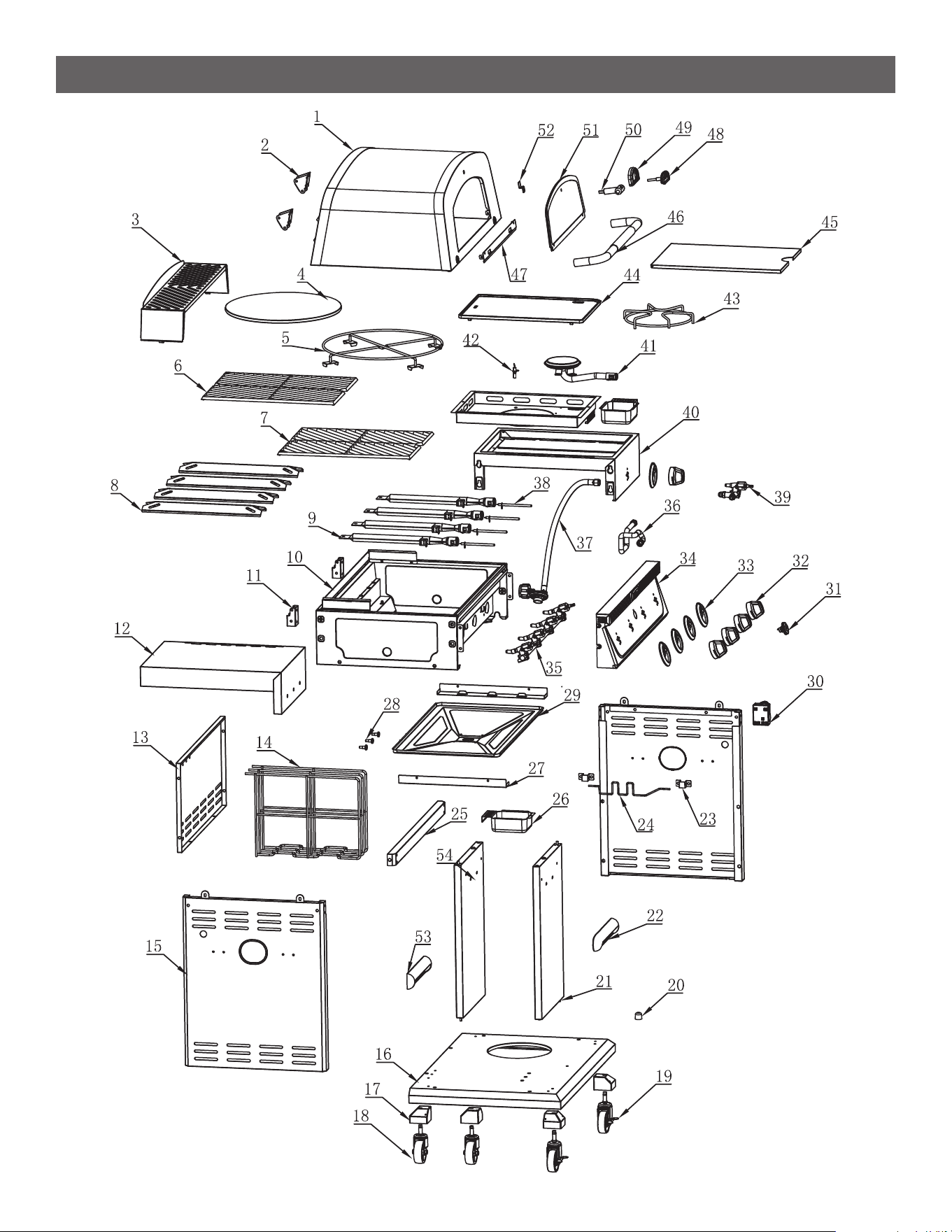
34
EXPLODED VIEW & PARTS LIST
35
EXPLODED VIEW & PARTS LIST
For replacement parts, call our customer service department 866-994-6390, 9 a.m.-5 p.m., EST, Monday-Friday
or email [email protected] NOTE: Not all parts are replaceable.
Part Description Quantity
1 Grill Lid 1
2 Lid Hinge- Top 2
3 Warming Rack 1
4 Pizza Stone 1
5 Pizza Stone Holder 1
6 Grill Grate Right 1
7 Grill Grate Left 1
8 Flame Tamers 4
9 Burners 4
10 Burner Box 1
11 Lid Hinge- Bottom 2
12 Side Table 1
13 Cabinet Rear Panel 1
14 Accessory Rack 3
15 Cabinet Side Panel 2
16 Cabinet Base 1
17 Caster Wheel Housing 4
18 Casters 2
19 Locking Casters 2
20 Door Bump 1
21 Right Cabinet Door 1
22 Left Cabinet Door Handle 1
23 Propane Tank Wire Brackets 2
24 Propane Tank Wire 1
25 Cabinet Front Beam 1
26 Grease Cup 2
27 Drip Tray Bracket 2
28 Tool Hooks 3
29 Grease Pan 1
30 Battery Box 1
31 Ignition Button 1
32 Control knobs 5
33 Knob Bezel 5
34 Control Panel 1
35 Gas Manifold Assembly 1
36 Flexible Gas Line 1
37 Gas Regulator & HoseAassembly 1
38 Burner Ignitor Pin 4
39 Side Burner Ignitor 1
40 Side Burner Fire Box 1
41 Side Burner 1
42 Side Burner Ignitor Pin 1
43 Side Burner Pot Rack 1
44 Griddle Plate 1
45 Griddle Plate Cover 1
46 Lid Handle 1
47 Pizza Door Hinge 1
48 Temperature Gauge 1
49 Temperature Gauge Support 1
50 Pizza Door Knob 1
51 Pizza Glass Door 1
52 Pizza Door Lock 1
53 Right Cabinet Door Handle 1
54 Left Cabinet Door 1

36
Questions, problems, missing parts? Before returning to your retailer,
call our customer service department at 866-994-6390, 9 a.m.-5 p.m.
EST, Monday-Friday or email [email protected]
Visit our website: www.cuisinart.com
2411
Model# CGG-6331
Cuisinart Outdoors a division of Conair LLC
Newton, MA 02466
Master Contract: 219529
WARRANTY AND REPLACEMENT PARTS
• This warranty covers defects in parts and workmanship for a period of 3 years from the original purchase date.
• Any damage claim regarding the enameling must be submitted within 30 days of purchase to be covered by
the warranty.
The following conditions are NOT covered by this warranty:
• Unevenness and color variations in the coated surfaces.
• Damage caused by improper assembly or disregard of the manual.
• Use of spare parts not supplied by manufacturer.
• Damage resulting from modications or inappropriate use.
• Abuse of the grill.
• Damage caused by improper maintenance or repairs by an unauthorized person.
Limitations and exclusions:
1. This warranty applies only to the original purchaser and may not be transferred.
2. If you can not verify the purchase date of the grill the warranty period will begin on the date the grill was
manufactured.
3. Replacement or repair parts are warranted for the remaining period of the original part warranty.
Your obligations:
• This grill must be assembled, installed, operated and maintained in accordance with all applicable codes and
the instruction manual furnished with this grill. You must keep an invoice, cancelled check or payment record
to verify the purchase date of the grill.