AP8805-21 (10/06)
Printed in USA
!
WITH INSTALLATION INSTRUCTIONS FOR THE CONTRACTOR
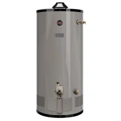
Light Duty Commercial Gas Water Heater
USE & CARE MANUAL
FOR YOUR SAFETY!
— Do not store or use gasoline or other flammable
vapors or liquids or other combustible materials in
the vicinity of this or any other appliance. To do so
may result in an explosion or fire.
— WHAT TO DO IF YOU SMELL GAS
•
Do not try to light any appliance.
•
Do not touch any electrical switch; do not use any
phone in your building.
•
Immediately call your gas supplier from a neighbor's
phone. Follow the gas supplier's instructions.
•
If you cannot reach your gas supplier, call the fire
department.
•
Do not return to your building until authorized by the
gas supplier or fire department.
— Improper installation, adjustment, alteration, service
or maintenance can cause injury, property damage
or death. Refer to this manual. Installation and
service must be performed by a qualified installer,
service agency or the gas supplier.
WARNING: If the information in these instructions are not followed exactly, a fire or explosion may result
causing property damage, personal injury or death.
NOTICE: This water heater is designed for use in a commercial application and the installation and maintenance of it should be
performed by qualified, licensed service personnel. If the foregoing assumption is not appropriate, then we recommend that you obtain
and retain our Residential Use & Care Manual.
!
!
!
CALIFORNIA PROPOSITION 65 WARNING:
This product contains chemicals known to the State of California to cause
cancer, birth defects or other reproductive harm.
!
Do Not Destroy this Manual. Please read carefully and
keep in a safe place for Future Reference.
Recognize this symbol as an Indication of Important
Safety Information!
!
!
D
E
S
I
G
N
C
E
R
T
I
F
I
E
D
®
CERTIFIED
R

2
General Safety Precautions
!
DANGER
!
FLAMMABLES
Flammable Vapors
Vapors from flammable
liquids will explode and
catch fire causing death or
severe burns
Do not use or store flammable
products such as gasoline,
solvents or adhesives in the
same room or area near the
water heater.
Keep flammable products:
1. far away from heater,
2. in approved containers,
3. tightly closed and
4. out of children's reach.
Water heater has a main
burner and pilot flame.
The pilot flame:
1. is on all the time and
2. will ignite flammable
vapors.
Vapors:
1. cannot be seen,
2. are heavier than air,
3. go a long way on the
floor and
4. can be carried from
other rooms to the pilot
flame by air currents.
Installation:
Do not install water heater
where flammable products will
be stored or used unless the
main burner and pilot flames
are at least 18" above the
floor. This will reduce, but not
eliminate, the risk of vapors
being ignited by the main
burner or pilot flame.
Read and follow water heater warnings and instructions. If owners
manual is missing, contact the retailer or manufacturer.
Be sure to read and understand the entire Use & Care Manual before attempting to install or operate this water heater. Pay particular attention to the following
General Safety Precautions. Failure to follow these warnings could result in a fire or explosion, causing property damage, bodily injury or death . Should you have
any problems understanding the instructions in this manual, STOP, and get help from a qualified installer or service technician or the gas supplier.
DANGER
!
DANGER
!
WARNING
!
Failure to install the draft hood and properly vent the water
heater to the outdoors as outlined in the Venting Section of
this manual can result in unsafe operation of the water heater.
To avoid the risk of fire, explosion, or asphyxiation from
carbon monoxide, never operate this water heater unless it is
properly vented and has an adequate air supply for proper
operation. Be sure to inspect the vent system for proper
installation at initial start-up; and at least annually thereafter.
Refer to Maintenance section of this manual for more
information regarding vent system inspections.
DANGER
!
WARNING
!
LIQUEFIED PETROLEUM MODELS — Propane, or LP gas,
must be used with great caution.
• It is heavier than air and will collect first in lower areas
making it hard to detect at nose level.
•
Make sure to look and smell for LP leaks before
attempting to light appliance. Use a soapy solution to
check all gas fittings and connections. Bubbling at a
connection indicates a leak that must be corrected. When
smelling to detect an LP leak, be sure to sniff near the
floor too.
• Gas detectors are recommended in LP applications and
their installation should be in accordance with the
manufacturer's recommendations and/or local laws, rules,
regulations or customs.
• It is recommended that more than one method be used to
detect leaks in LP applications.
IF LP GAS IS PRESENT OR SUSPECTED:
•
DO NOT
attempt to find the cause yourself;
•
DO NOT
try to light any appliance;
•
DO NOT
touch any electrical switch;
•
DO NOT
use any phone in your building.
• Leave the building immediately and make sure that
everyone else leaves also.
• Leave the doors open for ventilation and contact the gas
supplier, a qualified service agency or the fire department.
• Keep the area clear until the service call has been made,
the leak is corrected, and a qualified agency has
determined the area to be safe.
Gasoline, as well as other flammable materials and liquids
(adhesives, solvents, etc.), and the vapors they produce, are
extremely dangerous. DO NOT handle, use or store gasoline or
other flammable or combustible materials anywhere near or in the
vicinity of a water heater. Be sure to read and follow the warning
label pictured below and other labels on the water heater, as well
as the warnings printed in this manual. Failure to do so can result
in property damage, bodily injury, or death.
Both LP and natural gas have an odorant added to help
detection. Some people may not physically be able to smell or
recognize this odorant. If unsure or unfamiliar about the smell
associated with LP or natural gas, ask the gas supplier. Other
conditions, such as "Odorant Fade", which causes the
odorant to "fade", or diminish in intensity can also hide or
camouflage a gas leak.
!
Water heaters utilizing Liquefied Petroleum gas (LP) are
different from natural gas models. A natural gas heater will not
function safely on LP gas and vice versa. No attempt should
ever be made to convert a heater from natural gas to LP gas.
To avoid possible equipment damage, personal injury or fire:
DO NOT connect this water heater to a fuel type not in
accordance with unit data plate. Propane for propane units.
Natural gas for natural gas units. These units are not certified
for any other type fuel.
LP appliances should not be installed below-grade (for
example, in a basement) if such installation is prohibited by
federal, state and/or local laws, rules, regulations or customs.
WARNING
!
3
To meet commercial water use needs, the thermostat on this water
heater is adjustable up to 180°F. However, water temperatures over
125°F. can cause severe burns instantly or death from scalds. This
is the preferred starting point for setting the control for supplying
general purpose hot water.
Safety and energy conservation are factors to be considered when
setting the water temperature on the thermostat. The most energy
efficient operation will result when the temperature setting is the
lowest that satisfies the needs consistent with the application.
Maximum water temperatures occur just after burner has shut off.
To find hot water temperature being delivered, turn on a hot water
faucet and place a thermometer in the hot water stream and read
the thermometer.
General Safety Precautions
!
The following chart details the relationship of water temperature
and time with regard to scald injury and may be used as a guide in
determining the safest water temperature for your applications.
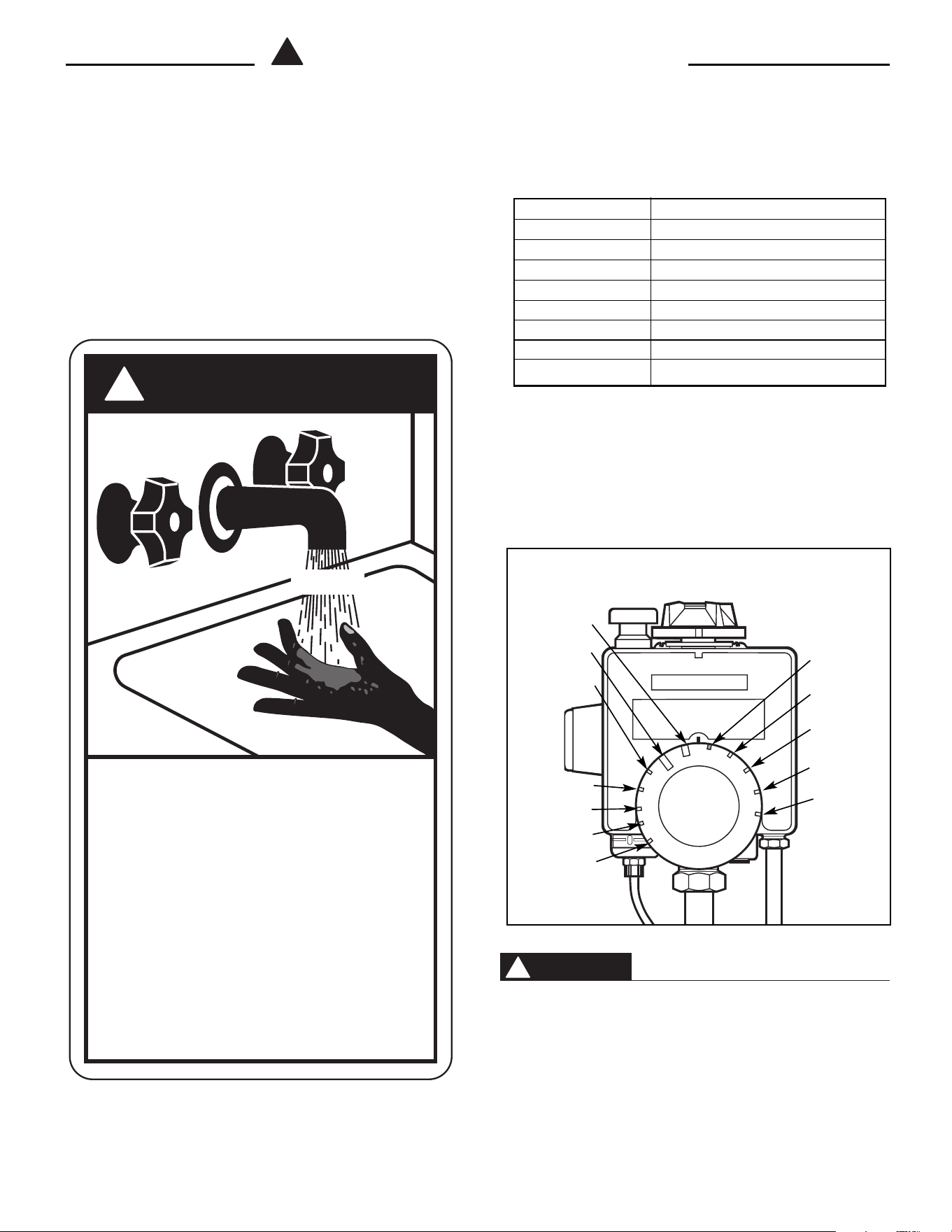
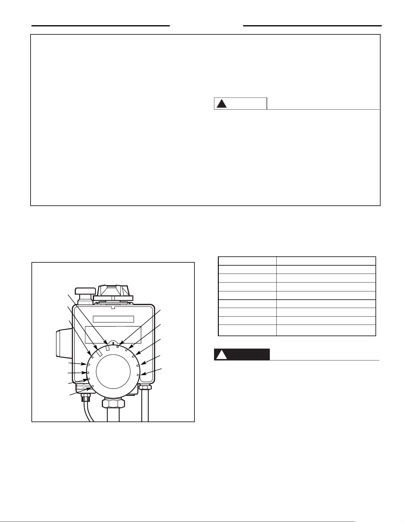
The temperature of the water in the heater can be regulated by
setting the temperature dial on front of the thermostat. To comply
with safety regulations the thermostat was set at its lowest setting
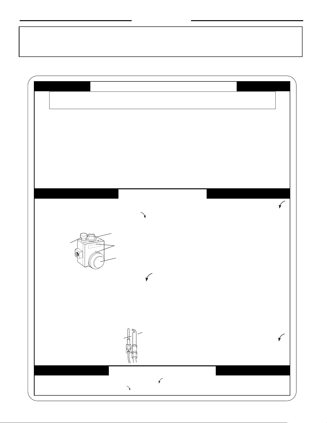
before water heater was shipped from the factory. The illustration
below illustrates the thermostat and how to adjust the water
temperature.
There is a Hot Water SCALD Potential if the thermostat is set too
high.
NOTE: When this water heater is supplying general purpose hot
water requirements for use by individuals, a thermostatically
controlled mixing valve for reducing point of use water
temperature is recommended to reduce the risk of scald injury.
Contact a licensed plumber or the local plumbing authority for
further information.
DANGER
!
HOT
Water temperature over 125°F can
cause severe burns instantly or
death from scalds.
Children, disabled and elderly are
at highest risk of being scalded.
See instruction manual before
setting temperature at water
heater.
Feel water before bathing or
showering.
Temperature limiting valves are
available, see manual.
BURN
Temperature Time to Produce Serious Burn
120° F. More than 5 minutes
125° F. 1
1
/
2
to 2 minutes
130° F. About 30 seconds
135° F. About 10 seconds
140° F. Less than 5 seconds
145° F. Less than 3 seconds
150° F. About 1
1
/
2
seconds
155° F. About 1 second
Table courtesy of Shriners Burn Institute
TIME / TEMPERATURE RELATIONSHIPS IN SCALDS
DANGER
!
U N I T R O L
WARNING
READ ALL INSTRUCTIONS
BEFORE LIGHTING
W
A
R
M
C
A
U
T
I
O
N
T
H
E
R
I
S
K
O
F
S
C
A
L
D
I
N
J
U
R
Y
W
A
T
E
R
I
N
C
R
E
A
S
E
S
H
O
T
T
E
R
V
E
R
Y
H
O
T
120°F. (Approx.)
115°F. (Approx.)
110°F. (Approx.)
100°F. (Approx.)
90°F. (Approx.)
130°F. (Approx.)
140°F. (Approx.)
150°F. (Approx.)
160°F. (Approx.)
170°F. (Approx.)
175°F. (Approx.)
180°F. (Approx.)
4
Read and Review this entire Manual with special emphasis on the
Venting Section (Page 6) and Operation Section (Pages 8 - 10) prior
to any installation work.
The location chosen for the water heater must take into considera-
tion the following:
LLOOCCAALL IINNSSTTAALLLLAATTIIOONN RREEGGUULLAATTIIOONNSS
This water heater must be installed in accordance with these in-
structions, local codes, utility company requirements, and/or in the
absence of local codes, the latest edition of the American National
Standard / National Fuel Gas Code. A copy can be purchased from
either American Gas Association, 400 N. Capitol Street, N. W., Wash-
ington, DC 20001 or from their web site (www.aga.org) as booklet
Z22399-IN1 or National Fire Prevention Association, 1 Batterymarch
Park, Quincy, MA 02269 or from their web site (www.nfpa.org) as
Item # 54HB99.
LLOOCCAATTIIOONN::
AA..
A gas fired water heater should not be installed in a space where
liquids which give off flammable vapors are to be used or stored.
Such liquids include gasoline, LP gas (butane and propane), paint
or adhesives and their thinners, solvents or removers. Because
of natural air movement in a room or other enclosed space,
flammable vapors can be carried some distance from where their
liquids are being used or stored. The open flame of the water
heater’s pilot light or main burner can ignite these vapors caus-
ing an explosion or fire which may result in severe burns or death
to those in range, as well as property damage. For these rea-
sons, installation of a gas fired water heater in a garage is not
desirable.
If a location in a garage is the only alternative, the gas water heater
should be installed so that the open flame of the pilot and main
burner are no less than 18 inches above the garage floor, unless
specifically exempted from this by local code, rule, regulation or
custom. Raising the gas fired water heater will reduce but not
eliminate the possibility of lighting the vapor of any flammable
liquids which may be improperly stored or accidentally spilled.
The water heater must be located or protected so it is not
subject to physical damage, for example, by moving vehi-
cles, area flooding etc.
Stand Kits to raise the water heater the required 18" above the
floor are available from the distributor or store where the
water heater was purchased.
BB..
The water heater should be installed as close as practical to the
gas vent or chimney. Long hot water lines should be insulated to
conserve water and energy. The water heater and water lines
should be protected from exposure to freezing temperatures. DO
NOT install the water heater in bathrooms, bedrooms, any oc-
cupied rooms normally kept closed, or in outdoor unprotected
areas.
CC..
Minimum clearance from combustible construction is 1 inch sides
and rear; 3 inches from front of control; 12 inches top. If clear-
ances stated on the Instruction/Warning label, located on front
of heater differ from the aforementioned clearances, install heater
according to clearances stated on the Instruction/Warning label.
The water heater may be installed on combustible floors, but not
directly on carpeting. If the water heater must be installed on car-
peting, place a metal or wood panel beneath the water heater ex-
tending beyond its full width and depth at least 3 inches in all di-
rections. If the water heater is installed in an alcove or closet,
the entire floor must be covered by the panel. A minimum of 24
inches clearance from the front and top should be available for ad-
equate inspection and servicing.
”Combustible construction” refers to adjacent walls and ceilings,
and should not be confused with combustible or flammable
products and materials. Combustible and/or flammable products
and materials should never be stored in the vicinity of this or any
gas appliance.
The water heater should not be located in an area where leakage of
the tank or connections will result in damage to the area adjacent
to it or to lower floors of the structure. When such areas cannot be
avoided, it is recommended that a suitable catch pan, adequately
drained, be installed under the water heater. The pan MUST NOT
restrict combustion air flow to bottom of water heater.
NNOOTTEE:: AAuuxxiilliiaarryy ccaattcchh ppaann iinnssttaallllaattiioonn MMUUSSTT ccoonnffoorrmm ttoo llooccaall
ccooddeess..
Catch Pan Kits are available in 16", 19", 22", 24", and 26
1
/2" di-
ameters from the distributor or store where the water heater was
purchased.
DD.. RREESSTTAAUURRAANNTTSS ——
If the water heater is to be installed in a restau-
rant or other location where the floor is frequently cleaned, it must
be elevated to provide at least six inches (15cm) of clearance from
the floor to comply with NSF /UL Sanitation recommendations. A
factory-designed leg extension kit is available for this purpose
from the distributor or store where the water heater was purchased.
EE.. CCOOMMBBUUSSTTIIOONN && VVEENNTTIILLAATTIIOONN AAIIRR ——
Proper operation of the
water heater requires outside air for combustion and ventilation.
If the water heater is installed in an unconfined space within a
building of conventional frame, masonry or metal construction,
infiltration air is normally adequate for proper combustion and
ventilation.
However, if the space is confined, provisions for this air must be
made. A confined space is one having a volume of less than 50
WARNING
!
CAUTION
!
WARNING
!
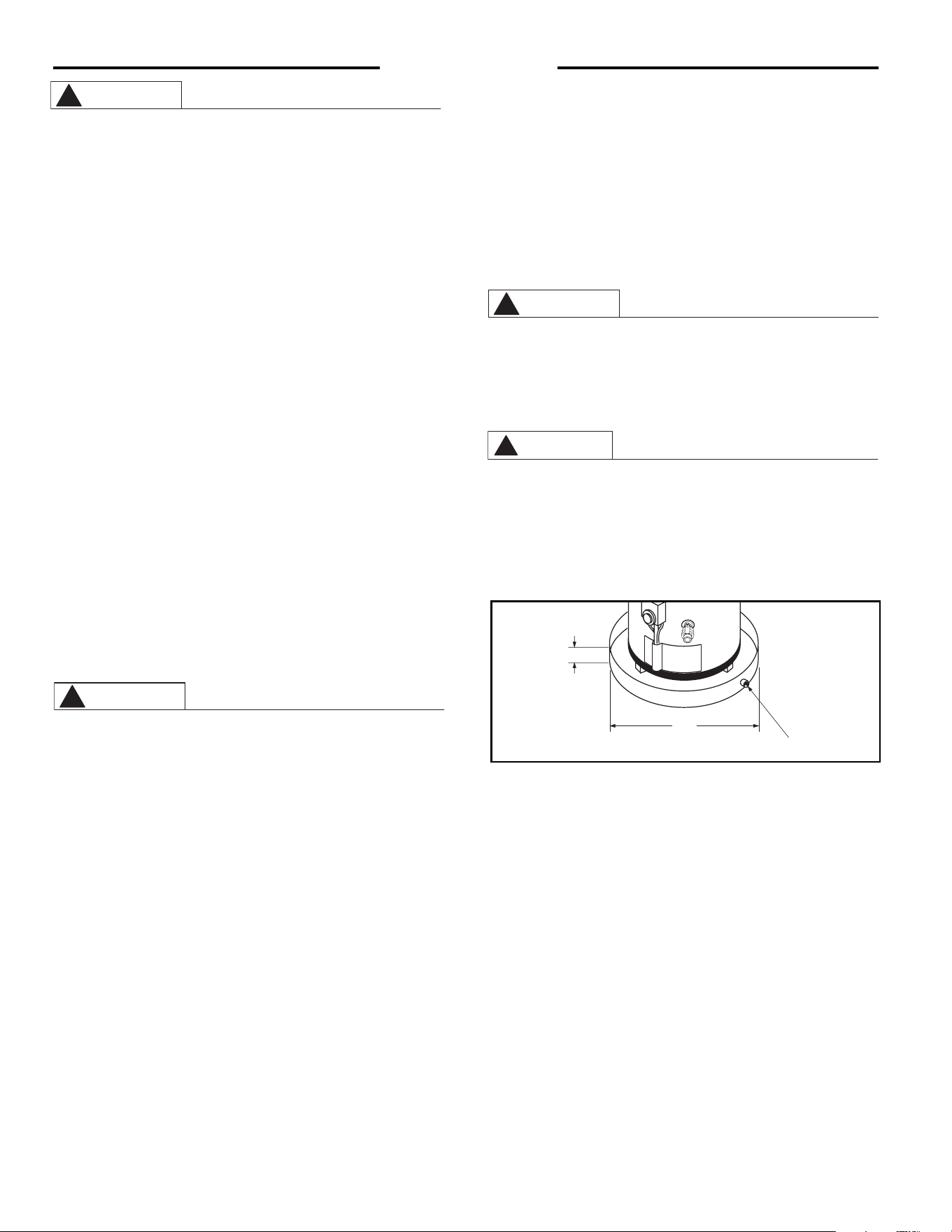
Introduction
A — Diameter of water
heater plus 2" min.
B — Maximum 2"
To open drain, line
should be at least
3
/4"
ID and pitched for
proper drainage.
Figure 1. — Auxiliary Catch Pan
WARNING
!
A
B
5
11.. IINNSSPPEECCTT SSHHIIPPMMEENNTT——
Inspect water heater for possible ship-
ping damage. Check the marking of the rating plate of the water
heater to be certain the type of gas being furnished corresponds
to that for which the water heater is equipped.
22..
TTHHEERRMMAALL EEXXPPAANNSSIIOONN —— DDeetteerrmmiinnee iiff aa cchheecckk vvaallvvee eexxiissttss iinn
tthhee iinnlleett wwaatteerr lliinnee..
It may have been installed in the cold water line
as a separate back flow preventer, or it may be part of a pres-
sure reducing valve, water meter or water softener. A check valve
located in the cold water inlet line can cause what is referred to
as a
””cclloosseedd wwaatteerr ssyysstteemm””
. A cold water inlet line with no check
valve or back flow prevention device is referred to as an ”open”
water system.
As water is heated, it expands in volume and creates an increase
in the pressure within the water system. This action is referred
to as
””tthheerrmmaall eexxppaannssiioonn””
. In an ”open” water system, expand-
ing water which exceeds the capacity of the water heater flows
back into the city main where the pressure is easily dissipated.
A
””cclloosseedd wwaatteerr ssyysstteemm””
, however, prevents the expanding water
from flowing back into the main supply line, and the result of
””tthheerr--
mmaall eexxppaannssiioonn””
can create a rapid, and dangerous pressure in-
crease in the water heater and system piping. This rapid pressure
increase can quickly reach the safety setting of the relief valve,
causing it to operate during each heating cycle. Thermal expan-
sion, and the resulting rapid, and repeated expansion and con-
traction of components in the water heater and piping system can
cause premature failure of the relief valve, and possibly the heater
itself.Replacing the relief valve
wwiillll nnoott
correct the problem!
The suggested method of controlling thermal expansion is to install
an expansion tank in the cold water line between the water heater and
the check valve. (refer to Figure 2.) The expansion tank is designed
with an air cushion built in that compresses as the system pressure
increases, thereby relieving the over pressure condition and elimi-
nating the repeated operation of the relief valve. Other methods of
controlling thermal expansion are also available. Contact your in-
cubic feet per 1000 Btu/hr of the aggregate input of all appliances
within that space.The air must be supplied through two perma-
nent openings of equal area, one of which is to be located with-
in 12 inches above the floor and the other is to be located within
12 inches below the ceiling. The minimum net free area of each
opening must be not less than one square inch per 1000 Btu/hr
of the total input rating of all the appliances in the enclosure (but
not less than 100 square inches), if each opening communicates
with other unconfined areas inside the building. Buildings of un-
usually tight construction shall have the combustion and venti-
lation air supplied from outdoors or a freely ventilated attic or
crawl space.
If air is supplied from outdoors, directly or through vertical ducts,
there must be two openings located as specified above and each
must have a minimum net free area of not less than one square
inch per 4000 Btu/hr of the total input rating of all the appliances
in the enclosure.
If horizontal ducts are used to communicate with the outdoors,
however, each opening must have a minimum net free area of
not less than one square inch per 2000 Btu/hr of the total input rat-
ing of all the appliances in the enclosure. If ducts are used, the
minimum dimension of rectangular air ducts shall be not less than
3 inches.
NOTE: If the openings are to be covered with a protective screen or
grill, the net free area of the covering material must be used in
determining the size of the openings, as stated above. Protective
screening for the openings MUST NOT be smaller than 1/4 inch
mesh to resist clogging by lint or other debris.
Provisions for combustion and ventilation air must comply with
referenced codes and standards. See Local Installation Regu-
lations Section on Page 4.
FF.. CCOORRRROOSSIIVVEE AATTMMOOSSPPHHEERREESS——
The water heater should not be
installed near an air supply containing halogenated hydrocar-
bons. For example, the air in beauty shops, drycleaning estab-
lishments, photo processing labs, and storage areas for liquid
and powdered bleaches or swimming pool chemicals often con-
tain such hydrocarbons. The air there maybe safe to breathe, but
when it passes through a gas flame, corrosive elements are re-
leased that will shorten the life of any gas burning appliance. Pro-
pellants from common spray cans or gas leaks from refrigeration
equipment are highly corrosive after passing through a flame.
The limited warranty is voided when failure of water heater is due
to a corrosive atmosphere. (Reference is made to the limited war-
ranty for complete terms and conditions.
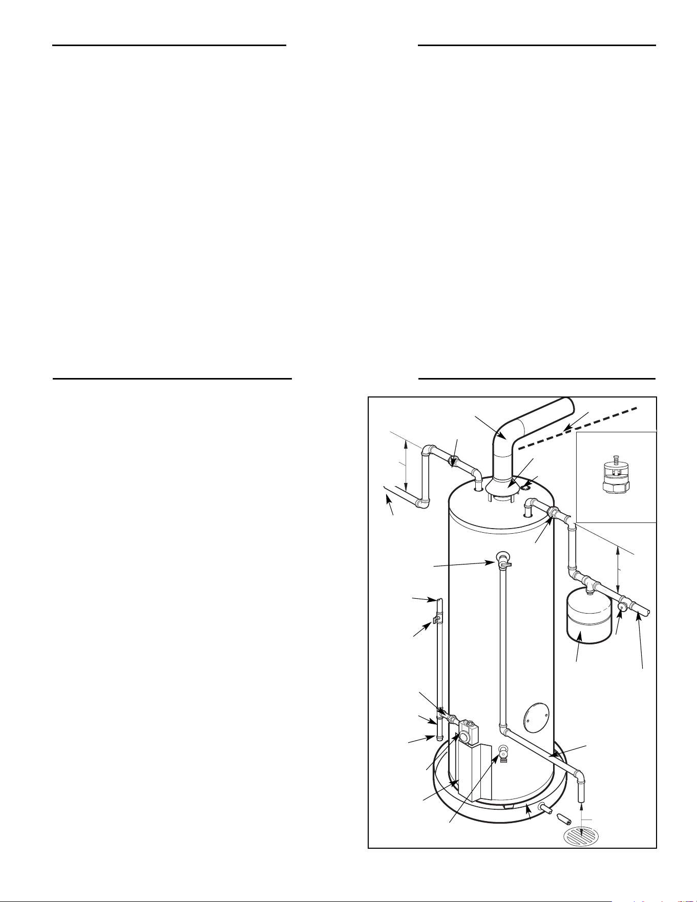
Installation
C
OL
D
H
O
T
Figure 2 — Typical Installation
Introduction
Relief Valve
Discharge Line to
Suitable Open Drain
Temperature &
Pressure
Relief Valve
Air Gap
6"
Shut-Off
Valve
To Cold
Water
Supply
Hot Water
Outlet
to Fixtures
Manual
Gas
Shut-Off
Auxiliary
Catch Pan
Expansion
Tank
(If Required)
To Gas
Supply
Union
Anode
Draft Hood
Vent Connector to Chimney
Pitch Up
1
/4" Per Foot
Ground Joint
Union
Full Flow
Drain Valve
Jacket Door
Thermostat
Cap
Union
Heat
Trap
6" Min.
Heat
Trap
6" Min.
Sediment
Trap
Vacuum Relief Valve
(Not Supplied)
If required, install per local codes
and valve manufacturer’s
instructions.
6
stalling contractor, water supplier, or plumbing inspector for additional
information regarding this subject.
WWAATTEERR SSUUPPPPLLYY CCOONNNNEECCTTIIOONNSS——
Refer to Fig. 2 for suggested
typical installation. The installation of unions or flexible copper
connectors is recommended on the HOT and COLD water lines,
so that the water heater may be easily disconnected for servic-
ing if necessary. The HOT and COLD water connections are clear-
ly marked.
Install a shut-off valve in the cold water line near water heater.
IIMMPPOORRTTAANNTT!!!! DDoo nnoott aappppllyy hheeaatt ttoo tthhee hhoott oorr ccoolldd hheeaatt ttrraapp nniipp--
pplleess..
IIff sswweeaatt ccoonnnneeccttiioonnss aarree uusseedd,, sswweeaatt ttuubbiinngg ttoo aaddaapptteerr bbee--
ffoorree ffiittttiinngg aaddaapptteerr ttoo hhoott wwaatteerr oouuttlleett oorr ccoolldd wwaatteerr iinnlleett ooff hheeaatteerr..
AAnnyy hheeaatt aapppplliieedd ttoo tthhee iinnlleett oorr oouuttlleett wwiillll ppeerrmmaanneennttllyy ddaammaaggee
tthhee
hheeaatt ttrraapp ffiittttiinnggss ssuupppplliieedd wwiitthh tthhee wwaatteerr hheeaatteerr oorr tthhee ddiipp
ttuubbee..
33..
RREELLIIEEFF VVAALLVVEE——
A new combination pressure and temperature
relief valve, complying with the Standard for Relief Valves and Au-
tomatic Gas Shutoff Devices for Hot Water Supply Systems, ANSI
Z21.22, or Standard CAN1-4.4, Temperature , Pressure, Temper-
ature and Pressure Relief Valves and Vacuum Relief Valves is pro-
vided with the water heater. No valve is to be installed between
the relief valve and the water heater.
The pressure rating of the
relief valve must not exceed 150 PSI, the maximum working pres-
sure of the water heater as marked on the front of the water heater.
The Btu/hr rating of the relief valve must equal or exceed the
Btu/hr input of the water heater as marked on its rating plate.
Connect the outlet of the relief valve to a suitable open drain.
Piping used should be of a type approved for hot water distribu-
tion. The discharge line must be no smaller than the outlet of the
valve and must pitch downward from the valve to allow complete
drainage (by gravity) of the relief valve and discharge line. The
end of the discharge line should not be threaded or concealed
and should be protected from freezing. No valve of any type, re-
striction or reducer coupling should be installed in the discharge
line.
44.. TTOO FFIILLLL WWAATTEERR HHEEAATTEERR——
Make certain drain valve is closed.
Open shut-off valve in cold water supply line. Open each hot
water faucet slowly to allow air to vent from the water heater and
piping. A steady flow of water from the hot water faucet(s) indi-
cates a fuIl water heater
Tank MUST be full of water before water heater is turned on. The
water heater’s warranty does not cover damage or failure resulting
from operation with an empty or partially empty tank (dry fired).
55.. GGAASS SSUUPPPPLLYY——
The branch gas supply line to the water heater should be
clean
1
/ 2 ’’ black steel pipe or other approved gas piping material. A ground
joint union or ANSI design certified semi-rigid or flexible gas appliance
connector should be installed in gas line close to the water heater, and a
manual gas shut-off valve should be installed in the gas line prior to the
union. The manual gas shut-off valve should be readily accessible for
turning on or off. A sediment trap should be installed at bottom of the gas
line. (Refer to Fig. 2)
Compound used on threaded joints of the gas piping must be of the type
resistant to the action of liquefied petroleum gas. Use compound sparingly
on male threads only. Do not use excessive force (over 31.5 Ft. Lbs.) in
tightening the pipe joint at the thermostat inlet, particularly if teflon pipe
compound is used, as the valve body may be damaged.
The inlet gas pressure to the water heater must not exceed 14” w.c. for
Natural or L.P. gas. For purposes of input adjustment, the minimum inlet
gas pressure (with main burner on) is shown on the water heater rating
plate. If high or low gas pressures are present, contact your gas supplier
for correction.
Do not attempt to convert this water heater for use with a
different type of gas other than the type shown on the
rating plate. Such conversion could result in hazardous
operating conditions.
66.. LLEEAAKK TTEESSTTIINNGG——
The water heater and its gas connections must
be leak tested at normal operating pressures before it is placed
in operation. Turn on the manual gas shut-off valve near the water
heater (Refer to Fig.2). Use a soapy water solution to test for
leaks at all connections and fittings. Bubbles indicate a gas leak
that must be corrected. The factory connections to the thermostat
should also be leak tested after the water heater is placed in op-
eration.
Never use open flame to test for gas leaks, as bodily injury,
property damage or death could result.
PPRREESSSSUURREE TTEESSTTIINNGG TTHHEE GGAASS SSUUPPPPLLYY SSYYSSTTEEMM ——
The water
heater and its manual gas shut-off valve must be disconnected
from the gas supply piping system during any high pressure test-
ing of that system at pressures in excess of
1
/2 psi (14” W.C.).
The water heater must be isolated from the gas piping system
by closing the manual gas shut-off valve (Refer to Fig. 2), dur-
ing any pressure testing of the gas supply piping at pressures
equal to or less than
1
/2 psi (14” W.C.).
77.. VVEENNTTIINNGG——
This water heater must be installed with the factory
supplied draft hood in place. (Refer to Fig. 2.) Vent connectors
must be attached to the draft hood outlet to connect the water
heater to the gas vent or chimney. The vent connectors must be
the same size (diameter) as the draft hood outlet or larger, never
smaller. For proper venting in certain installations, a larger vent
connector size may be needed. Consult Vent Tables in Appendix
“G” of the latest version of the National Fuel Gas Code or NFPA
booklet Z22399-IN1 .
Horizontal vent connectors must be pitched upward to the chim-
ney at least
1
/4” per foot of length. Single wall vent connectors
must be at least 6” from adjacent unprotected combustible sur-
faces. Joint of vent connectors should be securely fastened by
sheet metal screws or other approved method.
Installation
WARNING
!
WARNING
!
WARNING
!
7
Failure to install the draft hood and properly vent the water heater
to the outdoors as outlined above can result in unsafe operation of
the water heater causing bodily injury, explosion, fire or death. To
avoid the risk of fire, explosion, or asphyxiation from carbon
monoxide, NEVER operate this water heater unless it is properly
vented and has an adequate air supply for proper operation.
Be sure to inspect the vent system for proper installation at ini-
tial start-up and at least annually thereafter. Refer to Mainte-
nance section of this manual for more information regarding vent
system inspections.
The manufacturer’s warranty does not cover any damage or defect
caused by installation, attachment or use of any type of energy
saving or other unapproved devices (other than those authorized
by the manufacturer) into, onto or in conjunction with the water
heater. The use of unauthorized energy saving devices may
shorten the life of the water heater and may endanger life and
property. The manufacturer disclaims any responsibility for such
loss or injury resulting from the use of such unauthorized devices.
If local codes require external application of insulation blanket kits, the
instructions included with the kit must be carefully followed.
Application of any external insulation to this water heater will
require careful attention to the following:
•
Do not
apply insulation to top of water heater, as this will
interfere with the safe operation of the draft hood.
•
Do not
cover burner access panel, thermostat/gas valve or
pressure and temperature relief valve.
•
Do not
cover operating instructions or warning labels attached
to the water heater nor attempt to relocate them on the exterior
of the insulation blanket.
•
Do not
apply insulation to bottom or the 2” space between the
bottom pan of the water heater and the floor, as this area must
be unobstructed so as not to restrict combustion air flow to the
burner.
•
Do
inspect the insulation blanket frequently to make certain it
has not sagged and is restricting the combustion air to the
bottom of the water heater, as this could result in an unsafe
operating condition.
AA.. WWaatteerr HHeeaatteerr LLooccaattiioonn
❑
Close to area of vent.
❑
Indoors and protected from freezing temperatures.
❑
Proper clearance from combustible surfaces observed and
water heater not installed on carpeted floor.
❑
Sufficient fresh air supply for proper operation of water heater.
❑
Air supply free of corrosive elements and flammable vapors.
❑
Provisions made to protect area from water damage.
❑
Sufficient room to service heater.
BB.. WWaatteerr SSuuppppllyy
❑
Water heater completely filled with water.
❑
Water heater and piping air vented.
❑
Water connections tight and free of leaks.
CC.. GGaass SSuuppppllyy
❑
Gas line equipped with shut-off valve, union, and sediment
trap/drip leg.
❑
Approved pipe joint compound used.
❑
Soap and water solution used to check all connections and
fittings for possible gas leak.
❑
Gas Company inspected installation (if required).
DD.. RReelliieeff VVaallvvee
❑
Discharge line run to open drain.
❑
Discharge line protected from freezing.
EE.. VVeennttiinngg
❑
Flue baffle properly hung in top of heater’s flue.
❑
Draft hood properly installed.
❑
Vent connector(s) pitched upward to chimney (
1
/
4” per foot
of length minimum) .
❑
Vent connector(s) securely fastened together with screws.
❑
Single wall vent connector(s) at least 6” from combustible
material.
Installation Check List
WARNING
!
Installation
WARNING
!
DANGER
!
8
Before operating this water heater, be sure to read and follow the instructions on the label pictured below and all other labels on the water
heater, as well as the warnings printed in this manual. Failure to do so can result in unsafe operation of the water heater resulting in
property damage, bodily injury, or death. Should you have any problems reading or following the instructions in this manual, STOP, and
get help from a qualified person.
11.. LLIIGGHHTTIINNGG PPRROOCCEEDDUURREE --
Lighting procedures are outlined on the label pictured below. This label is also located on the water heater near the thermostat.
Operation
A. This appliance has a pilot which must be lighted by hand.
When lighting the pilot, follow these instructions exactly.
B. BEFORE PUTTING THIS APPLIANCE INTO SERVICE—
Smell all around the appliance area for gas. Be sure to
smell next to the floor because some gas is heavier than
air and will settle on the floor.
WHAT TO DO IF YOU SMELL GAS:
• Do not try to light the appliance.
• Do not touch any electrical switch; do not use any
phone in your building.
• Immediately call your gas supplier from a neighbor's
phone. Follow the gas supplier's instructions.
• If you cannot reach your gas supplier, call the fire de-
partment.
C. Use only your hand to turn the gas control knob. Never
use tools. If the knob will not turn by hand, don't try to
repair it, call a qualified service technician. Force or
attempted repair may result in fire or explosion.
D. Do not use this appliance if any part has been under
water. Immediately call a qualified service technician
to inspect the appliance and to replace any part of the
control system and any gas valve that has been under
water.
FFOORR YYOOUURR SSAAFFEETTYY RREEAADD BBEEFFOORREE OOPPEERRAATTIINNGG
LLIIGGHHTTIINNGG IINNSSTTRRUUCCTTIIOONNSS
TTOO TTUURRNN OOFFFF GGAASS TTOO AAPPPPLLIIAANNCCEE
WARNING: If you do not follow these instructions exactly, a fire or explosion may
result causing property damage, personal injury or loss of life.
11.. SSTTOOPP!! RREEAADD TTHHEE SSAAFFEETTYY IINNFFOORRMMAATTIIOONN AABBOOVVEE OONN
TTHHIISS LLAABBEELL..
2. TURN GAS COCK KNOB CLOCKWISE TO "OFF"
POSITION.
3. TURN TEMPERATURE DIAL COUNTER CLOCK-
WISE TO LOWEST SETTING
4. WAIT FIVE (5) MINUTES TO CLEAR OUT ANY GAS. IF
YOU SMELL GAS, STOP! FOLLOW "B" IN THE SAFE-
TY INFORMATION ABOVE ON THIS LABEL. IF YOU
DON'T SMELL GAS, GO TO THE NEXT STEP.
5. REMOVE BOTH THE INNER DOOR AND OUTER DOOR
FROM THE WATER HEATER.
6. FOLLOW THE METAL TUBES FROM GAS CONTROL
THRU DOOR OPENINGS. THE PILOT
IS LOCATED ON THE
HORIZONTAL LEG
OF THE LARGER TUBE (OR BURN-
ER).
7. TURN THE GAS COCK KNOB COUNTER CLOCKWISE
TO "PILOT" POSITION.
8. PUSH DOWN ON THE "RED BUTTON" UNTIL IT COMES
TO REST ON THE TOP OF CONTROL. IT MUST CLEAR
THE NOTCH PROVIDED IN THE "GAS COCK KNOB". HOLD
"RED BUTTON" DOWN AND LIGHT THE PILOT WITH A
MATCH. CONTINUE TO HOLD THE"RED BUTTON" IN FOR
ABOUT ONE (1) MINUTE AFTER THE PILOT IS LIT . RE-
LEASE BUTTON AND IT WILL POP BACK UP. PILOT
SHOULD REMAIN LIT. IF IT GOES OUT, REPEAT STEPS
2 THROUGH 8.
•
IF THE BUTTON DOES NOT POP BACK UP WHEN RE-
LEASED, STOP AND IMMEDIATELY CALL YOUR SER-
VICE TECHNICIAN OR GAS SUPPLIER.
• IF THE PILOT WILL NOT STAY LIT AFTER SEVERAL
TRIES, TURN THE "GAS COCK KNOB" TO "OFF" AND
CALL YOUR SERVICE TECHNICIAN OR GAS SUPPLI-
ER.
9. REPLACE INNER AND OUTER DOORS.
10. TURN "GAS COCK KNOB" COUNTER CLOCKWISE
TO "ON".
11. TURN THE TEMPERATURE DIAL TO THE DESIRED SET-
TING.
UNITROL
RED BUTTON
INDEX
PILOT
BURNER
TEMPERATURE
DIAL
GAS COCK
KNOB
THERMOCOUPLE
1. TURN TEMPERATURE DIAL COUNTER CLOCKWISE TO LOWEST SETTING.
2. TURN GAS COCK KNOB CLOCKWISE TO "OFF POSITION.
9
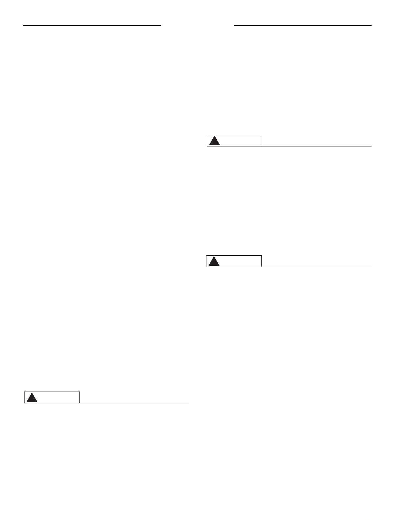
22.. WWAATTEERR TTEEMMPPEERRAATTUURREE SSEETTTTIINNGG——
The temperature of the
water in the heater can be regulated by setting the temperature dial
on front of the thermostat. (Refer to Fig. 3) To comply with safe-
ty regulations the thermostat was set at its lowest setting before
water heater was shipped from the factory. A setting of 120°F.,
or lower if local codes require, is recommended as a starting point.
The ”RED” reference mark near “WARM” on rim of temperature
dial, represents an approximate water temperature of 120°F. The
wide reference mark, to the left, represents an approximate water
temperature of 130°F. Each reference mark above or below these
points indicates an approximate change of 10°F.
Safety and energy conservation are factors to be considered
when selecting the water temperature setting of water heater’s
thermostat. The lower the setting the greater the safety and sav-
ings in energy and operating cost.
There is a Hot Water SCALD Potential if the thermostat is set
too high.
NOTE: Households with small children or invalids may require a
120°F. or lower thermostat setting to prevent contact with “HOT”
water.
Maximum water temperatures occur just after burner has shut
off. To find hot water temperature being delivered, turn on a hot
water faucet and place a thermometer in the hot water stream
and read the thermometer.
Figure 3 — Thermostatic Gas Valve.
Temperature Time to Produce Serious Burn
120° F More than 5 minutes
125° F 1
1
/
2
to 2 minutes
130° F About 30 seconds
135° F About 10 seconds
140° F Less than 5 seconds
145° F Less than 3 seconds
150° F About 1
1
/
2
seconds
155° F About 1 second
Table courtesy of Shriners Burn Institute
TIME / TEMPERATURE RELATIONSHIPS IN SCALDS
DANGER
!
Operation
CAUTION
!
AA..
DDoo
turn off manual gas shut-off valve if water heater has been
subjected to over heating, fire, flood, physical damage, or if gas
supply fails to shut off.
BB..
DDoo NNoott
turn on water heater unless it is filled with water.
CC..
DDoo NNoott
turn on water heater if cold water supply shut-off valve
is closed.
DD..
DDoo NNoott
store or use gasoline or other flammable vapors and liq-
uids, such as adhesives or paint thinner, in vicinity of this or any
other appliance. If such flammables must be used, open doors
and windows for ventilation, and all gas burning appliances in
vicinity should be shut off, including their pilot lights, to avoid ig-
niting vapors that may be present.
NNOOTTEE:: FFllaammmmaabbllee vvaappoorrss mmaayy bbee ddrraawwnn bbyy aaiirr ccuurrrreennttss ffrroomm ssuurr--
rroouunnddiinngg aarreeaass ttoo tthhee wwaatteerr hheeaatteerr..
E
E..
DDoo nnoott
allow combustible materials such as newspaper, rags, or
mops to accumulate near water heater.
FF..
If there is any difficulty in understanding or following the OPER-
ATION or MAINTENANCE instructions, it is recommended that a
qualified person or serviceman perform the work.
Hydrogen gas can be produced in a hot water system
served by this water heater that has not been used for a
long period of time (generally two weeks or more).
HYDROGEN GAS IS EXTREMELY FLAMMABLE!! To
dissipate such gas and to reduce risk of injury, it is
recommended that the hot water faucet be opened for
several minutes at the kitchen sink before using any
electrical appliance connected to the hot water system. If
hydrogen is present, there will probably be an unusual
sound such as air escaping through the pipe as the water
begins to flow.
Do not
smoke or use an open flame near the
faucet at the time it is open.
CAUTION
!
SAFETY PRECAUTIONS
U N I T R O L
WARNING
READ ALL INSTRUCTIONS
BEFORE LIGHTING
W
A
R
M
C
A
U
T
I
O
N
T
H
E
R
I
S
K
O
F
S
C
A
L
D
I
N
J
U
R
Y
W
A
T
E
R
I
N
C
R
E
A
S
E
S
H
O
T
T
E
R
V
E
R
Y
H
O
T
120°F. (Approx.)
115°F. (Approx.)
110°F. (Approx.)
100°F. (Approx.)
90°F. (Approx.)
130°F. (Approx.)
140°F. (Approx.)
150°F. (Approx.)
160°F. (Approx.)
170°F. (Approx.)
175°F. (Approx.)
180°F. (Approx.)
10
Mixing valves for reducing point of use water temperature by mix-
ing hot and cold water in branch water lines are available. Con-
tact a licensed plumber or the local plumbing authority for fur-
ther information.
33.. AADDJJUUSSTTMMEENNTTSS --
The thermostatic gas valve is equipped for
total regulation of the main burner and pilot gas pressures and
does not require adjustment.
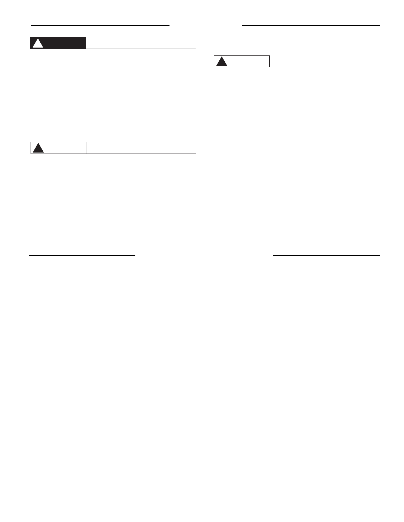
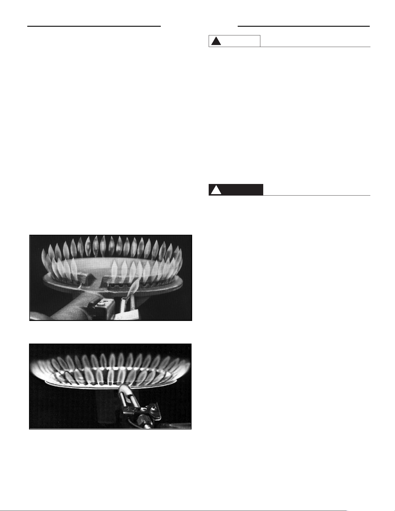
BBUURRNNEERR AADDJJUUSSTTMMEENNTT ——
If this heater is supplied with a cast
iron burner, the heater may require a primary air adjustment at the
time of installation. An air shutter is located at the air opening
end of the burner. To adjust the burner, loosen air shutter screw
and close to soften flame and open shutter to sharpen the flame.
The proper flame should be soft blue, not yellow or with a hard
blue center (Refer to Fig. 4). Final air adjustment should be made
after 5 minutes of continuous burning. The sheet metal burner
does not require adjustment (Refer to Fig. 5)
HHIIGGHH AALLTTIITTUUDDEE——
Ratings of gas appliances are based on sea
level operation and need not be changed for installations at el-
evations up to 2,000 feet. For installations above 2,000 feet, the
input must be reduced per the National Fuel Gas Code for each
1,000 feet above sea level. Contact the local gas supplier for fur-
ther information.
44.. SSAAFFEETTYY CCOONNTTRROOLLSS——
The thermostat is constructed with a
built in safety shut-off device designed to shut off the gas supply
to the burner in the event the pilot flame is extinguished for any
reason. The thermostat is also equipped with single use gas shut-
off device that will shut off the gas supply to the burner, if the
water in the water heater exceeds normal operating tempera-
tures. Refer to the Troubleshooting Section of this manual, or
contact your dealer for service.
55.. EEMMEERRGGEENNCCYY SSHHUUTTDDOOWWNN——
Should overheating occur or the gas supply fail to shut off, turn off
the manual gas control valve to the appliance.
If water heater has been subjected to fire, flood, or physical dam-
age turn off the manual gas control (shut-off) valve, and do not
operate the water heater again until it has been checked by qual-
ified personnel.
NNOOTTEE:: RReeppllaaccee aannyy ppaarrtt ooff tthhee ggaass ccoonnttrrooll ssyysstteemm wwhhiicchh hhaass
bbeeeenn uunnddeerr wwaatteerr..
66.. CCOONNDDEENNSSAATTIIOONN——
Condensation can form on the tank when it
is first filled with cold water. The condensation might also occur
with a heavy water draw and very cold inlet water. Drops of water
falling on the burner can produce a sizzling or pinging sound,
and water may also be seen beneath the water heater. This con-
dition is not unusual, and will disappear after the water in the
water heater becomes heated. If, however, the condition is con-
tinuous, examine the piping and fittings for possible leaks.
77.. VVA
ACCAATTIIOONN AANNDD LLOONNGG TTIIMMEE SSHHUUTT--DDOOWWNN——
If the water heater
is to remain idle for an extended period of time, the gas should be
turned off to conserve energy. The water heater and piping should
be drained if they might be subjected to freezing temperatures.
NNOOTTEE:: RReeffeerr ttoo HHyyddrrooggeenn GGaass CCaauuttiioonn,, iinn SSaaffeettyy PPrreeccaauuttiioonnss
SSeeccttiioonn oonn ppaaggee 99..
After a very long shut-down period, the water heater’s operation
and controls should be checked by qualified service personnel.
Make certain the water heater is completely filled before plac-
ing it in operation again.
88.. DDRRAAIINNIINNGG WWAATTEERR HHEEAATTEERR——
Shut off gas at thermostat gas cock or supply line manual shut-off
valve before draining water from the water heater.
In order to drain water, turn off cold water supply, then it is nec-
essary to open a hot water faucet or lift the handle on the relief
valve to admit air to the tank. Attach a garden hose to the drain
valve on the water heater and direct the stream of water to a drain
where it will do no damage.
The water drained from the tank may be hot enough to present a
SCALD HAZARD and should be directed to a suitable drain to
prevent injury or damage.
99.. AANNOODDEE——
This water heater is equipped with an anode rod de-
signed to prolong the life of the glass lined tank. Refer to Fig.2 for
location. The anode rod is slowly consumed cathodically, there-
by eliminating or minimizing corrosion of the glass lined tank.
Water sometimes contains a high sulfate and/or mineral content
and together with the cathodic protection process can produce a
hydrogen sulfide or rotten egg odor in the heated water. Chlori-
nation of the water supply should minimize the problem.
NNOOTTEE:: DDoo nnoott rreemmoovvee tthhee aannooddee rroodd ffrroomm tthhee wwaatteerr hheeaatteerr’’ss ttaannkk,,
eexxcceepptt ffoorr iinnssppeeccttiioonn aannd
d//oorr rreeppllaacceemmeenntt,, aass ooppeerraattiioonn wwiitthh tthhee
aannooddee rroodd rreemmoovveedd wwiillll ggrreeaattllyy sshhoorrtteenn tthhee lliiffee ooff tthhee ggllaassss
lliinneedd
ttaannkk aanndd wwiillll eexxcclluuddee wwaarrrraannttyy ccoovveerraaggee..
CAUTION
!
DANGER
!
Operation
11
11.. RROOUUTTIINNEE PPRREEVVEENNTTAATTIIVVEE MMAAIINNTTEENNAANNCCEE
Properly maintained, your water heater will provide years of de-
pendable trouble free service. It is suggested that a regular routine
maintenance program be established and followed by the user. It is
further recommended that a periodic inspection of the thermostat,
burner, relief valve, internal flueway and venting system should be
made by service personnel qualified in gas appliance repair.
AA..
The water heater’s internal flue must be inspected annually to
be certain it is clean by removing the draft hood and flue baffle.
When reinstalling the flue baffle make certain it is hung secure-
ly by its hanger at the top of the flue way. Remove any scale that
may have fallen on the burner or floor shield. Reinstall the draft
hood.
Inspect gas venting system to make certain vent connector from
draft hood to chimney is properly positioned and securely at-
tached and inspect chimney. Replace any corroded through vent
connector and remove any obstruction in vent connector or chim-
ney.
BB..
Visually inspect the burner annually while firing and pilot burn-
er flame with main burner off. (Refer to Fig. 4 or 5 for normal
flame pattern.) If any unusual burner operation is noted, the
water heater should be shut off until qualified service assistance
can be obtained.
For cleaning, remove the burner from the water heater. A vacu-
um cleaner can be used on the burner and floor shield inside the
water heater. The burner can also be cleaned by scrubbing with
mild detergent.
For your safety, cleaning of main burner should be performed
ONLY by qualified service personnel, as it involves disconnection
of gas piping and leak testing.
CC..
The area near the water heater must be kept free of flammable liq-
uids such as gasoline or paint thinners, adhesives and other com-
bustible materials.
DD..
For adequate combustion (proper burner operation) and venti-
lation, make certain the flow of air to the water heater is not ob-
structed.
EE..
At least once a year, lift and release the lever handle on the tem-
perature pressure relief valve, located near the top of the water
heater, to make certain the valve operates freely and allow sev-
eral gallons to flush through discharge line. Make certain the dis-
charged water is directed to an open drain.
Before manually operating the relief valve, make certain no one will
be exposed to the danger of coming in contact with the hot water
released by this valve. The water may be hot enough to create a
SCALD hazard. The water released should be directed to a suitable
drain to prevent injury or damage.
NNOOTTEE:: IIff tthhee tteemmppeerraattuurree aanndd pprreessssuurree rreelliieeff vvaallvvee oonn tthhee wwaatteerr
hheeaatteerr ddiisscchhaarrggeess ppeerriiooddiiccaallllyy,, tthhiiss mmaayy bbee dduuee ttoo tthheerrmmaall eexx--
ppaannssiioonn iinn aa ““CClloosseedd”” wwaatteerr ssyysstteemm.. CCoonnttaacctt tthhee wwaatteerr ssuupppplliieerr
oorr yyoouurr pplluummbbiinngg ccoonnttrraaccttoorr oonn hhooww ttoo ccoorrrreecctt tthhiiss.. DDOO NNOOTT pplluugg
tthhee rreelliieeff vvaallvvee oouuttlleett..
FF..
A water heater’s tank can act as a settling basin for solids suspended in
the water. It is, therefore, not uncommon for hard water deposits to
accumulate in the bottom of the tank. Deposits should not be allowed to
accumulate as this can affect the service life of the water heater. It is
suggested that a few quarts of water be drained from the water heater’s
tank every month. If sufficient hard water deposits accumulate, a rumbling
or pounding sound can occur. There is no danger involved and the
efficiency of the water heater is not seriously affected, but the noise can
be annoying. Your plumbing contractor should be contacted to clean the
tank of these deposits.
GG..
Rapid closing of faucets or solenoid valves in automatic water
using appliances can cause a pounding “water hammer” sound.
“Water hammer” can be described as a banging noise heard in a
water pipe following an abrupt alteration of the flow with result-
ing pressure surges. Strategically located risers in the water pipe
system can be used to minimize the problem. Also water ham-
mer arresting devices are usually available from your plumber
or local plumbing supply store.
22.. AANNOODDEE RROOD
D IINNSSPPEECCTTIIOONN——
The anode rod should be removed
from the water heater’s tank annually for inspection and replaced
when more than 6” of core wire is exposed at either end of the rod.
Refer to Fig. 2 for anode rod location. Make certain cold water
supply is turned off before removing anode rod.
Maintenance
CAUTION
!
DANGER
!
Figure 4. — Main Burner and Pilot Flame Pattern
(Cast Iron Burner)
Figure 5. — Main Burner and Pilot Flame Pattern
(Sheet Metal Burner)
12
For your safety, DO NOT attempt repair of gas piping, thermostat, burners, vent connectors or other safety devices. Refer repairs to qualified
service personnel.
CAUTION
!
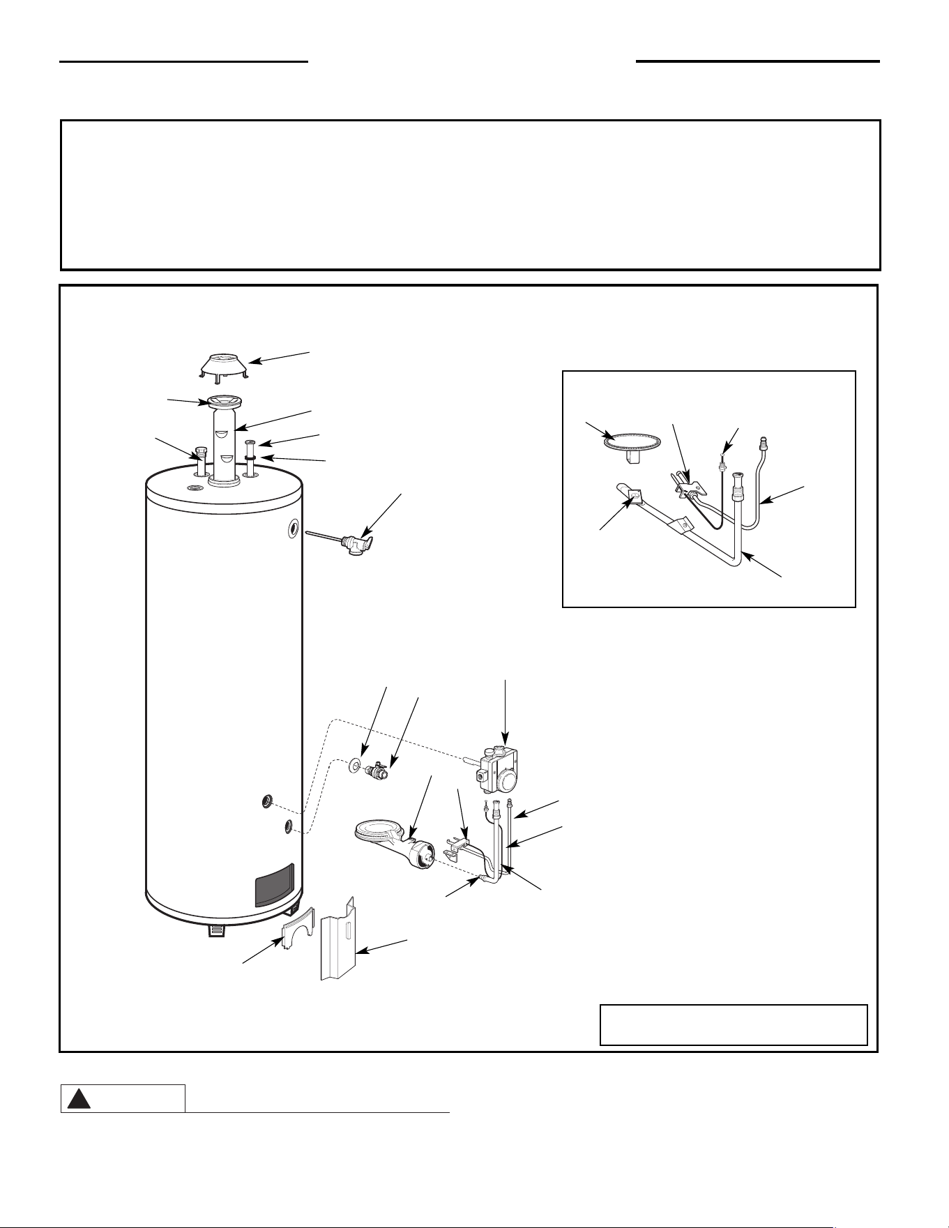
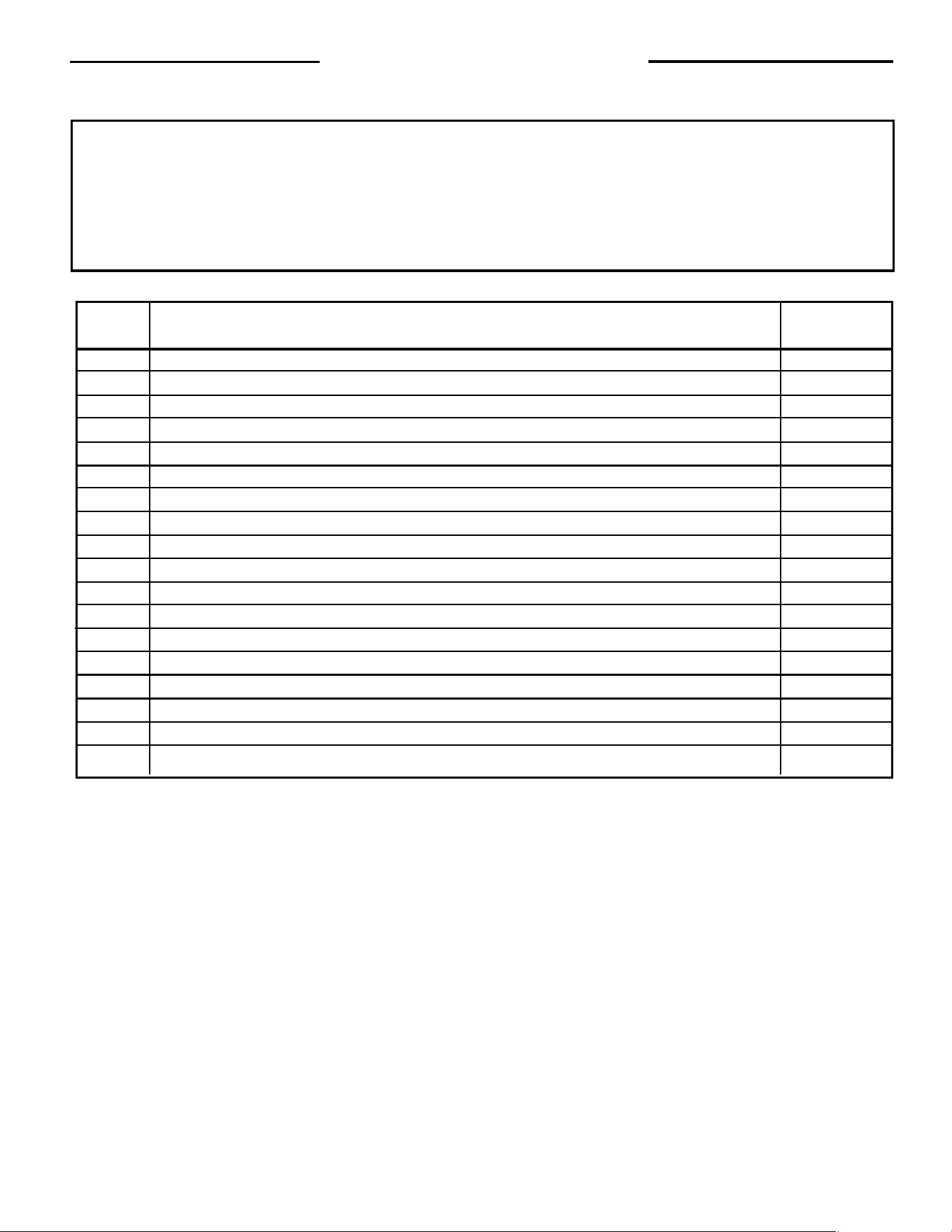
Replacement Parts List
IInnssttrruuccttiioonnss ffoorr ppllaacciinngg aa PPaarrttss OOrrddeerr::
Address parts orders to the distributor or store from where the heater was purchased.
All parts orders should include:
1. Model number and Serial number of heater (from rating plate).
2. Specify type of gas (Natural or LP) as listed on rating plate.
3. Part Description (as noted below) and number of parts desired.
Light Duty Models
Natural or LP Gas
1
2
3
4
5
10
11
6
7
8
12
13
14
16
15
17
18*
9**
4
2
6
5
7
3
For models equipped with Sheet Metal Burner
* Top Mounted on Select Models
** Standard Drain Valve on Select Models
13
Replacement Parts List
IInnssttrruuccttiioonnss ffoorr ppllaacciinngg aa PPaarrttss OOrrddeerr::
Address parts orders to the distributor or store from where the heater was purchased.
All parts orders should include:
1. Model number and Serial number of heater (from rating plate).
2. Specify type of gas (Natural or LP) as listed on rating plate.
3. Part Description (as noted below) and number of parts desired.
Light Duty Models
Natural or LP Gas
Ref. Qty.
No. Part Description Req’d
1. Thermostat 1
2. Pilot Supply Tube 1
3. Thermocouple 1
4. Burner Supply Tube 1
5. Burner Orifice 1
6. Burner 1
7. Pilot Burner 1
8. Drain Valve Shroud 1
9. Drain Valve 1
10. Jacket Door 1
11. Inner Door 1
12. Flue Baffle 1
13. Flue Baffle Collar 1
14. Anode Rod 1
15. Draft Hood 1
16. Dip Tube 1
17. Dip Tube Gasket 1
18. T&P Relief Valve 1
14
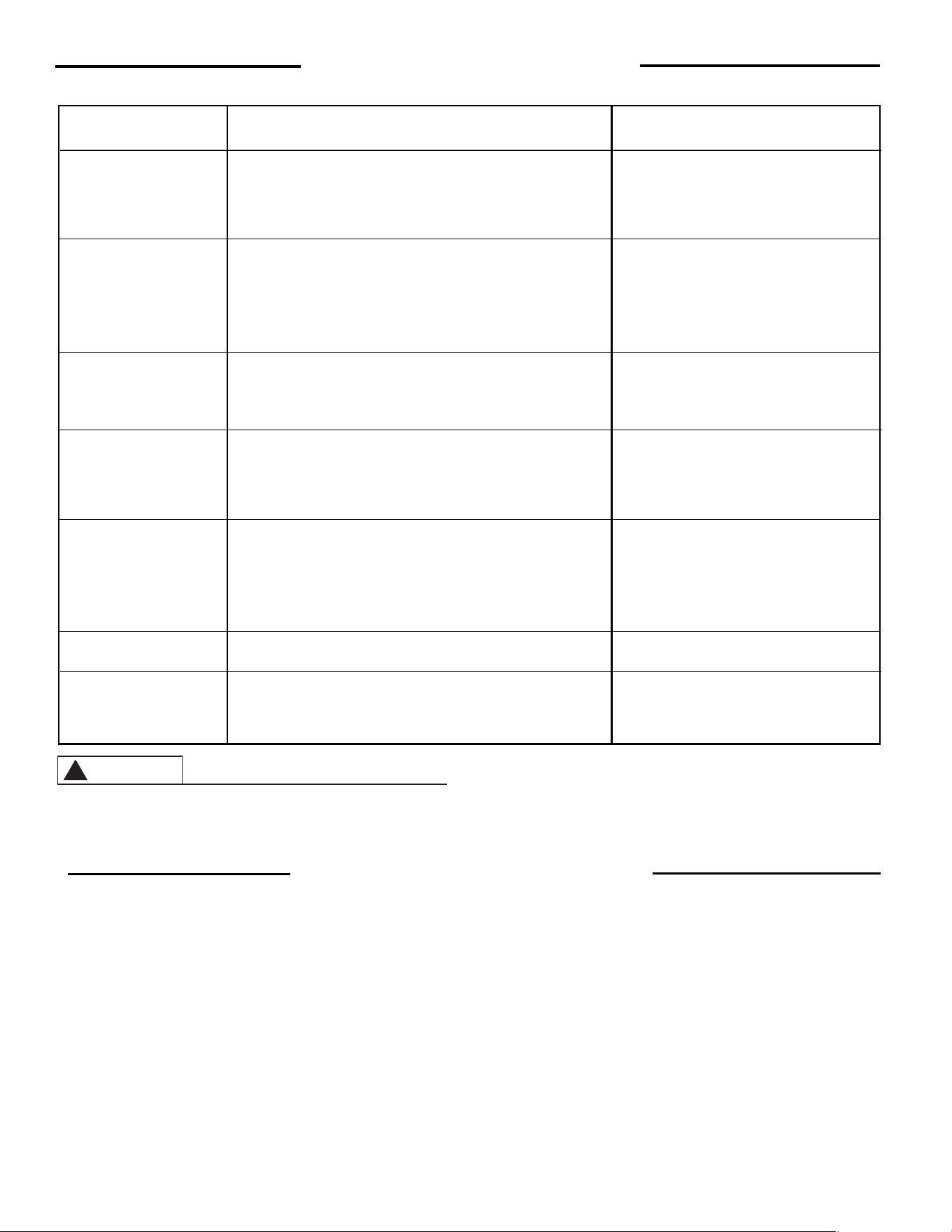
NATURE OF TROUBLE POSSIBLE CAUSE SERVICE
Unable to light pilot 1. Gas knob dial not correctly positioned Follow lighting instructions
2. Pilot orifice clogged ** Clean or replace
3. Pilot tube pinched or clogged. ** Clean, repair or replace
4. Air in gas line ** Purge air from gas line
Pilot does not stay lit 1. Loose Thermocouple ** Tighten connection at thermostat
when red button is released 2. Thermocouple breakdown ** Replace
3. Safety magnet breakdown ** Replace thermostat
4. Thermostat's single use gas shut-off ** Replace thermostat
device has opened
Not enough hot water 1. Heater undersized Reduce rate of hot water usage
2. Low gas pressure ** Check gas supply pressure and
manifold pressure
Water too hot or not 1. Thermostat setting too high or low Change setting as required
hot enough 2. Thermostat out of calibration ** Replace
3. High water temperature followed by ** Thermostat out of calibration, replace
pilot outage.
Yellow flame 1. Scale on top of burner Shut off heater and remove scale
Sooting 2. Combustion air inlets or flueway Remove lint or debris and inspect air
restricted inlet opening for restriction
3. Not enough combustion or ventilation air Refer to Sec. E in Introduction
supplied to the room section of this manual
Rumbling noise 1. Scale or sediment in tank Clean tank - See Maintenance, Sec.F
Rattling noise during 1. Heat Trap fittings in operation (If heater is equipped with these None. The rattling noise is normal for
periods of water usage energy saving devices) Heat Trap fittings when in operation and
does not indicate a need for service.
Trouble Shooting Guide
** For your safety, DO NOT attempt repair of thermostat, burners or gas piping. Refer repairs to qualified service personnel.
CAUTION
!
1. Should you have any questions about your new water heater, or
if it requires adjustment, repair, or routine maintenance, it is sug-
gested that you first contact your installer, plumbing contractor
or previously agreed upon service agency. In the event that the
firm has moved, or is unavailable, refer to the telephone direc-
tory commercial listings or local utility for qualified service as-
sistance.
2. Should your problem not be solved to your complete satisfac-
tion, you should then contact the Manufacturer’s National Ser-
vice Department at the following address:
2600 Gunter Park Drive
Montgomery, Alabama 36109-1413
Phone: 1-800-432-8373.
When contacting the manufacturer, the following information
should be made available:
a. Model and serial numbers of the water heater as shown on the
rating plate attached to the jacket of the heater.
b. Address where water heater is located and can be seen.
c. Name and address of installer and any service agency who per-
formed service on the water heater.
d. Date of original installation and dates any service work was per-
formed.
e. Details of the problem as you can best describe them.
f. List of people, with dates, who have been contacted regarding
your problem.
How to Obtain Service Assistance

15
THIS PAGE WAS INTENTIONALLY LEFT BLANK.

16
THIS PAGE WAS INTENTIONALLY LEFT BLANK.