Pre-Engineered Walk-In Coolers and Freezers
Installation Manual
UPDATED: 2/2019 Instruction Manual IM-268-11 2017© Bally Refrigerated Boxes, Inc. 1
Part One: The Bally Walk-In
1. Preparation for Installing the Walk-In ___________________________________________________ 3
2. Operation of the Bally Speed-Lok _____________________________________________________ 3
Part Two: Installation
1. Positioning ______________________________________________________________________ 4
2. Walk-Ins with Screeds ______________________________________________________________ 4
3. Installing Less-Floor Walk-Ins _________________________________________________________ 4
4. Door Installation __________________________________________________________________ 5
5. Installing With-Floor Walk-Ins ________________________________________________________ 5
6. Vertical and Ceiling Panel Installation __________________________________________________ 5
7. Installing Multi-Compartment Walk-Ins _________________________________________________ 6
Part Three: Other Important Information
1. Preventing Vapor Leaks _____________________________________________________________ 6
2. Partition Wall Caulking _____________________________________________________________ 7
3. Air Gap Circulation Recommendation _________________________________________________ 7
4. Making holes for Refrigeration Tubing and Electrical Lines __________________________________ 7
5. Making Electrical Connections to Entrance Doors and Vapor-proof Lights ______________________ 7
Part Four: Completing the Bally Installation
Completing Installation of the Walk-In ___________________________________________________ 9
1-800-24BALLY | [email protected]
UPDATED: 4/2017 Instruction Manual IM-268-11 2017© Bally Refrigerated Boxes, Inc. 2
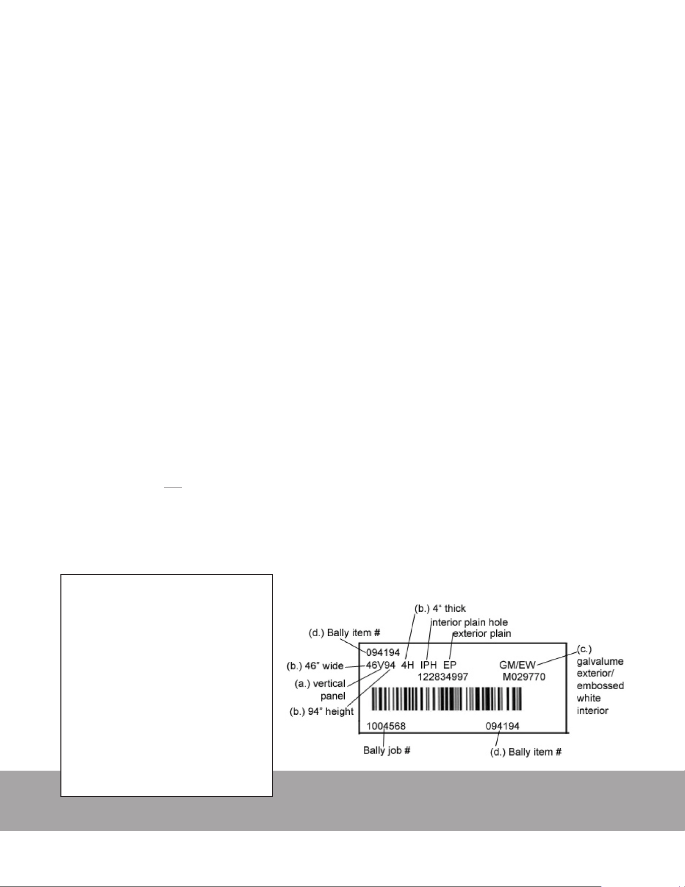
Bally identies panels with
barcode labels that specify:
a. Panel type:
FLR- Floor
CLG- Ceiling
V- Vertical
VC- Vertical corner
BKR- Breaker
b. Panel dimensions
c. Panel nishes
Listed Exterior/Interior
d. Bally Part# and Serial#
For immediate service, call Bally’s Parts and Service Hotline toll-free: 1-800-344-9302
Miscellaneous Box #1 with the orange sticker
contains all the information you will need.
• Before attempting to install the Bally Walk-In, review these instructions and any others supplied
with the shipment.
• For future reference, make sure there is a record of the original order number and a list of all se-
rial numbers for the Walk-In and refrigeration systems.
• A plan view showing the proper layout of panels is enclosed with other documents as well as this
manual. Make sure you are using the “As-Built” drawings as opposed to any previously supplied
“Proposal” drawings.
• Before placing any panel into position, check the plan view for location.
1. Installation Preparation
A. When the building is delivered, make sure you have the right equipment and manpower on hand to unload the truck. A fork-
lift or high jack can be helpful if the shipment includes heavy steel or refrigeration equipment. The carrier typically imposes
time constraints on unloading your box, and in all situations one person is not enough.
B. As you are unloading look for any freight damage; all products left our factory in perfect condition. Once the Bill of Landing
was signed by the carrier, safe delivery became their responsibility and the equipment became your property. Check the
packing list and make sure that all component parts are accounted for. Before signing the Bill of Landing, inspect all items.
If any damage is noted or the number of pieces received does not agree with the invoice, do not accept shipment without
notation by the carrier’s agent on the Freight Bill. If damage or shortage is discovered when unpacking leave material and
request an inspection by the carrier. Keep all documents and information so you can le you claim properly with the carrier.
The Bill of Landing, Freight Bill, and the original invoice, are needed to le a claim, and must be led within one week of the
date of shipment.
C. Use extreme caution when unpacking to prevent damage to panels and other equipment. Pay close attention to hardware
axed to the door and door-frame. Do not lift the door by its Hardware or the Light Base. Do not drop panels or slide over
unnished surfaces. Keep panels dry and out of direct sunlight.
D. The protective plastic coating on the panels may be removed before or after the installation depending on the timing of
construction schedules. The protective plastic on the bottom of the oor panels must be removed prior to setting the oors
in place. In all cases, ALL plastic must be removed before the nal completion of the installation. This includes all unexposed
areas and all surfaces under membrane roofs.
E. The most important requirement for installation of this Walk-In is to have a level oor. If the oor is level the process will be
very smooth. Otherwise, it’s impossible to make sure that the panels will align correctly and be plumb and level. Use a laser
level or transit to identify the high spots on the oor. Whenever Walk-Ins are to be installed where concrete is curing or tile is
being set, it is important to provide adequate ventilation. Concrete and tile grout release hydrogen while curing, which can
damage the panel nishes, especially any type of Aluminum nish.
UPDATED: 2/2019 Instruction Manual IM-268-11 2017© Bally Refrigerated Boxes, Inc. 3
Always refer to your Plan View when installing your Bally Walk-In Cooler or Freezer.
2. Operation of the Bally Speed-Lok:
A. Before attempting to erect panels, familiarize yourself with the operation of the locks Figures 2, 3, and 4. On Bally panels, locks
will always be on the left turning in clockwise rotation. If for any reason you have to unlock a panel, refer to Section B below.
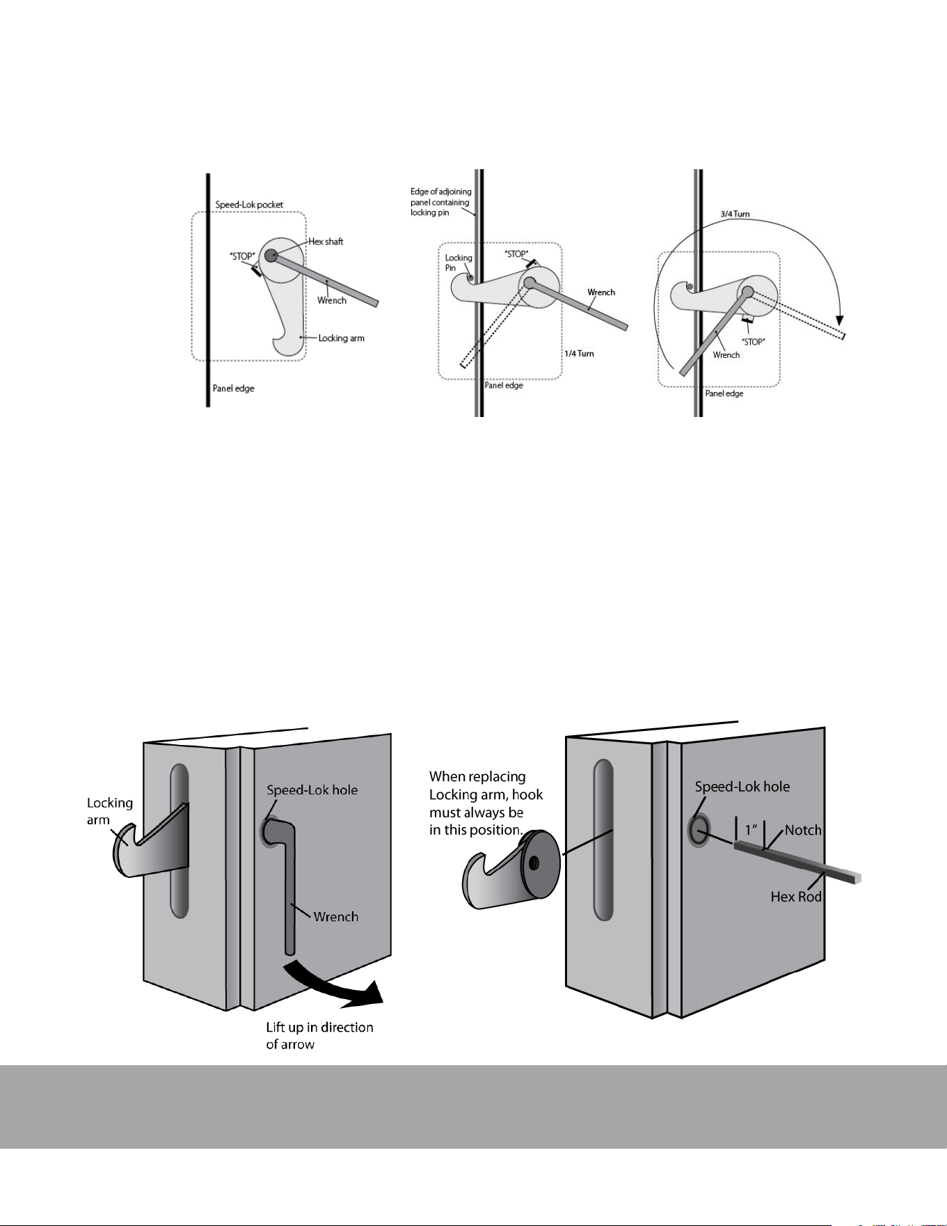
B. Replacing broken or stripped locks
1. The panel contained the lock must be slid away from adjacent panels in order to obtain adequate working space. First check
for any obstructions (dirt, foam, etc.) once you have unlocked a panel reset the cam stop by turning the lock fully back to its
original position. If the hook is broken or stripped replacements can be found in Miscellaneous Parts Box#1.
2. Position the lock wrench on the hex rod and turn clock-wise until the locking arm protrudes.
3. Place your hand near the bend in the wrench and use a lift-up motion. This will produce a clamping action on the hex rod.
While doing this, pull forward until the rod is free of the panel. The locking arm will then drop free. See Figure 2.
4. Hold the new locking arm in position. Make sure the hook of the arm faces in the proper direction. See Figure 3.
5. Insert the new hex rod into the lock hole. Care must be taken to insert the notched end of the rod. The end to be inserted
has a notch located 1” from the end. This notch acts as a stop so the rod will not be inserted too far.
6. Align the hex rod with the hex hold of the locking arm; gently tap it until the notch stops against the locking arm.
7. Replace and refasten the panel in its original position.
Figure 1
Figure 2
Figure 3
UPDATED: 2/2019 Instruction Manual IM-268-11 2017© Bally Refrigerated Boxes, Inc. 4
Figure 4
Figure 5
Part Two: Installation
1. Positioning
Walk-Ins erected near existing building walls must be posi-
tioned with minimum 2” clearance to allow for air circulation
and prevent possible condensation on the exterior surface
of the Walk-In. It is important to check that the building’s
walls are square and plumb, if they are not this will have to
be taken into account when erecting the sidewalls. If re-
frigeration and coil drain tubing is to be run between Walk-
In and building wall allow space for installation. Check for
overhead objects that will intrude the Walk-Ins height. De-
pending on temperature and humidity, air circulation may
be needed to equalize the air temperature and the panel
surface temperature above the dew point; this is usually re-
quired in a dead air space and high humidity environment.
2. Walk-Ins with Screeds
If any part of your Walk-In employs screeds, lock the screeds
to the bottoms of the panels before placing any vertical
panels. Vinyl oor screeds are anchored to concrete in less-
oor Walk-Ins via drive pins with sleeve anchors provided by
Bally. Drill into the concrete or other surface with a masonry
bit. When using vinyl screeds, shim to make sure panels
are level inside the screed. If the Walk-In is being installed
on quarry tile, oor holes may be drilled to hit tile seams.
Check all dimensions before proceeding.
3. Assembly of Less-Floor Walk-Ins
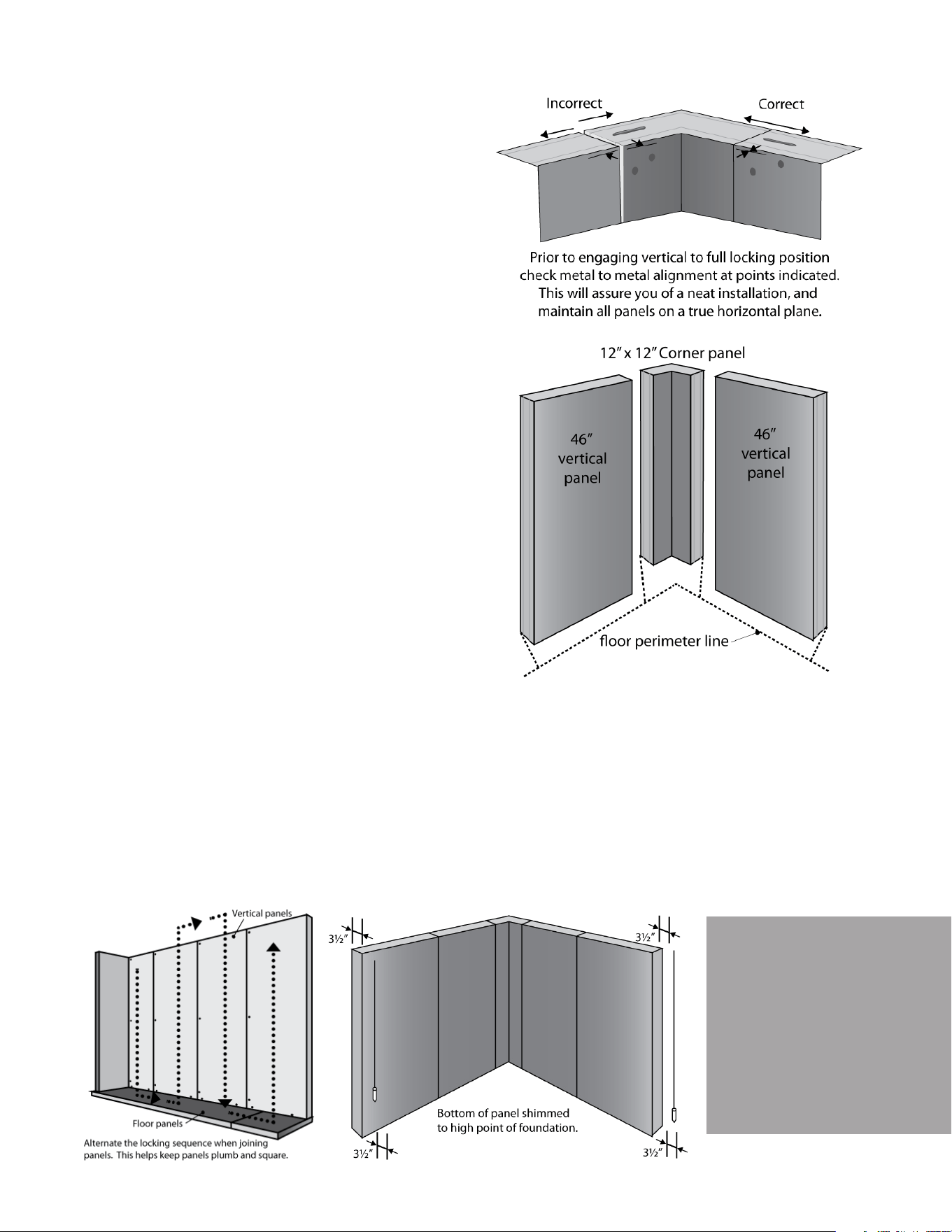
A. After you have checked that the building oor is level,
use a transient or builders level to nd the highest point
on the perimeter. Position the rst 12” x 12” corner to be
level with the high point. Begin at corner and align pan-
els at the top. See Figure 4.
B. Position a vertical panel to the right and left of the corner panel (as per Plan View) and ush with the perimeter line. Once
properly aligned, fully engage all vertical-to-vertical locks. See Figure 5.
C. Level panels to the perimeter high point and check for plumb with a 48” spirit level. (Panels over 10’ high use a plumb bob.)
See Figure 7.
D. As each panel is installed, check to make sure it’s plumb and level. If the panel is not plumb, shim to adjust for plumb. Making
the same check down the panel’s leading edge shows whether it’s level along the top or not. If not adjust accordingly.
E. Continue installing vertical panels in the same manner, periodically checking to make sure that panels remain plumb and
level. See Figure 6 (staggered locking sequence).
F. When enough vertical panels are set to accept the installation of the rst ceiling and end panel, begin assembly of the ceiling
panels. See Section 6 for method of installing remaining vertical and ceiling panels.
G. With installation complete, caulk the bases of the vertical panels where they meet the concrete oor.
Figure 6
Figure 7
Always check to
make sure that
each new panel is
level and plumb.
UPDATED: 2/2019 Instruction Manual IM-268-11 2017© Bally Refrigerated Boxes, Inc. 5
Figure 8
4. Door Installation
A. When erecting a door panel for an installation on a concrete oor and without Bally
oor panels, it is necessary to provide a cutout in the concrete oor for all freezer
applications so that the heater channel may be inserted to prevent icing. Doors
intended for Coolers are simply set on top of the concrete.
• If your door sticks out at the top, your frame is not plumb. Move the bottom of the
frame in or out to correct this problem.
• If the gap at the top of the door is inconsistent, your frame is not level and the door
latch may not work properly. Shim the low side of the frame to level it with the
high side.
B. Caulk and seal any gaps under panels or door to oor. Apply base trim as per plan
view. For outdoor installation it is recommended that all exterior panel joints be
caulked during installation.
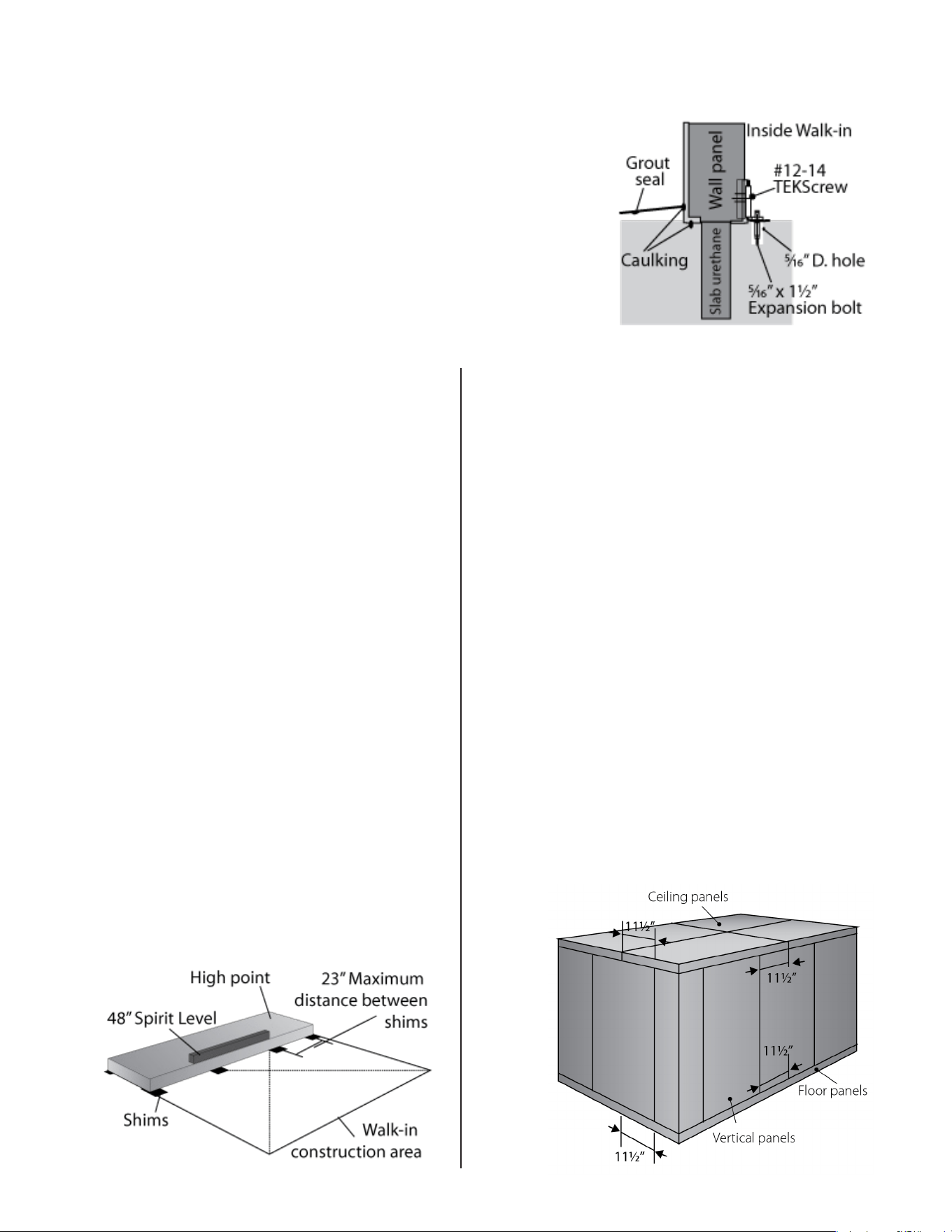
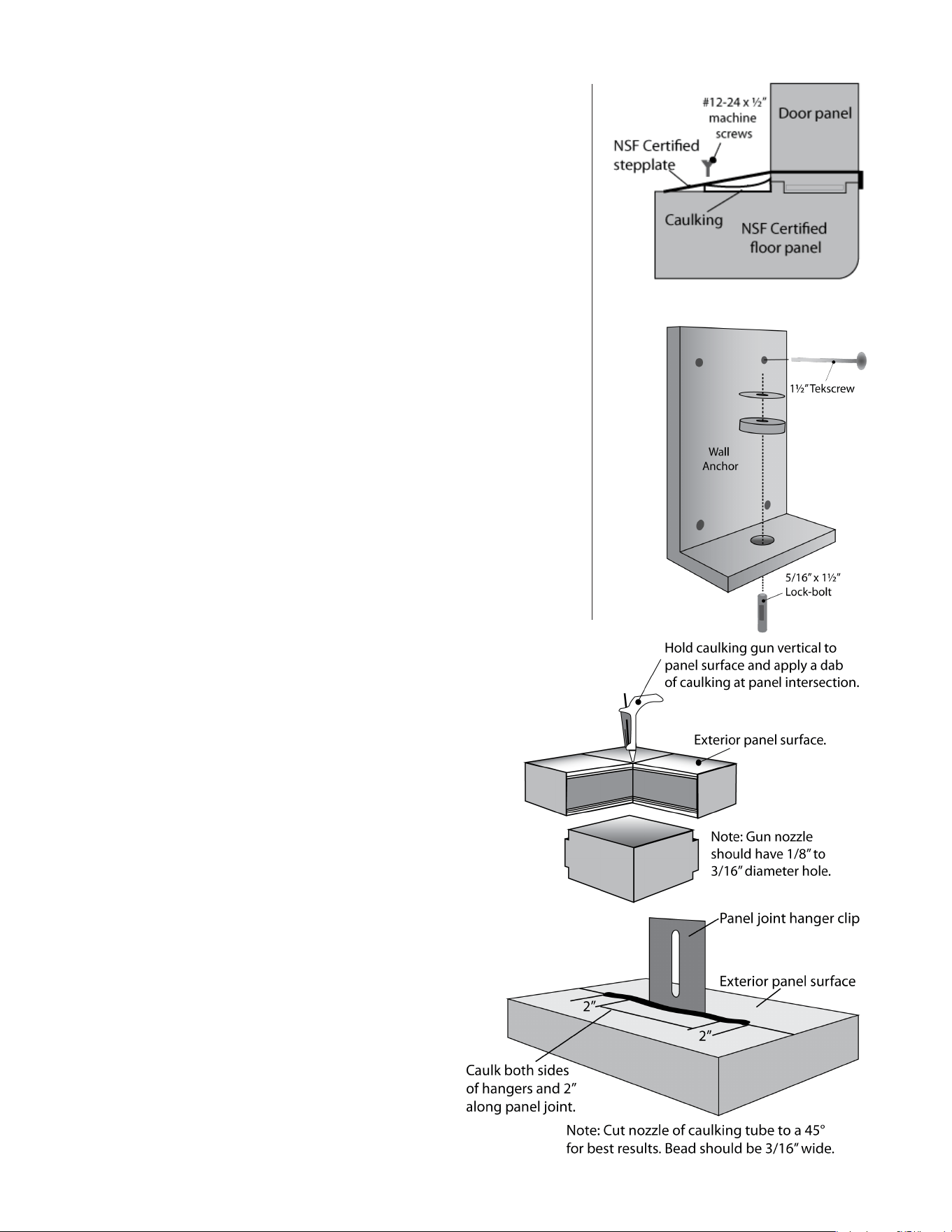
C. Anchor panels to oor using either Continuous Angle provided or, for outdoor boxes,
L-bracket attachments known as WA-1 or Wa-2. See Figure 8.
5. Assembly of With-Floor Walk-Ins
A. Make sure the oor is level. The entire area beneath the
Walk-In oor should be covered with a heavy polyethyl-
ene vapor barrier to prevent possible damage by moisture.
(Check state and local codes to determine the mil thickness.)
B. Check plan view for any special panel conguration, then
place a 23½” wide oor end panel along the most logical
starting point (usually the furthest corner from existing build-
ing wall). Level the oor panel to high point of concrete
slab. See Figure 9.
C. Install the next panel and align. Level to the high point of
the concrete slab every time a new panel is installed.
D. Install shims (Bally recommends asphalt shingles) under cor-
ners and cross panel joints as needed to ensure proper sup-
port and levelness of panels. Be sure the shims are not more
than 23” apart at any given point under the panel. Place ad-
ditional shims, equally spaced, along the door frame area
for proper support, and to eliminate potential sagging.
E. Continue to install oor panels as per Plan View, locking each
panel to its adjoining panel, and keeping ends of panels
even. Continue until all oor panels are assembled, check
for levelness and squareness. (Adjust if necessary.)
F. Check bottom section of door to be used to insure the prop-
er door is in the correct location. Doors are specically lo-
cated by the oor plan drawing which is enclosed with the
installation instructions (A freezer door may have a dierent
stepplate condition than a cooler door Follow the sux 01 – 02
that corresponds to the drawing).
G. If structural steel is required it should be located and in-
stalled before installing further.
6. Vertical and Ceiling Panel Installation
A. Determine the critical areas to nd a starting point (For smaller
Walk-Ins this is the door location); this section must be perfectly
plumb and square to insure proper operation of the door.
B. Begin by erecting a vertical corner panel (If the Walk-In is being
installed near a building start at a corner nearest that). Speed-Lok
holes are always on the left when facing the interior of the panel.
C. Erect the vertical panels to the right and left of the corner pan-
el (Check the plan view), align tops of the panels and check for
plumb and level. Lock panels together, check to be sure the
proper metal nish is exposed where specied on the plan view.
D. When enough vertical panels have been set to allow installation
of the rst ceiling panel, install the panel walls in an order that
will allow a ceiling section to be installed before proceeding with
more panel walls. Fasten ceiling panels to one another. When
a few are in place, lock the rst ceiling panel to vertical panels.
E. To check for correct alignment measure the distance from the
edge of the ceiling or oor to the nearest vertical joint. This
should be 11½” and maintained at every joint of the Walk-In. Use
a staggered locking sequence as shown in Figure 6. See Figure 10.
F. When all walls and ceiling panels are in place, lock all vertical pan-
els to oor panels. Door sections are held down through the
threshold plate. Drill through thresholds’ pre-drilled holes into
oor. Secure to oor with screws provided. See Figure 11.
G. For a Walk-In requiring anchors on the outside of the walls, begin
by centering anchors WA-3 to vertical panel joints and WA-4 to
corners. See Figure 12.
Figure 9
Figure 10
UPDATED: 2/2019 Instruction Manual IM-268-11 2017© Bally Refrigerated Boxes, Inc. 6
7. Installing Multi-Compartment Walk-Ins
A. The most common arrangement for a Walk-In is a two compartment cooler/
freezer combination. Installation of panels in this situation is the same as de-
scribed above. The use of a “Breaker” or “Tee” panel is used to separate the
dierent compartments. These panels will be either 23” or 46”; typically the
verticals are the opposite of the ceilings and oors.
B. The Partition Wall will have at least two special panels referred to as P-1 and
P-2. The panel widths are either 7.6” or 19.1” and are marked with a special blue
sticker that corresponds to the drawing. The P-2 panels are double tongued
(has hook pockets on both sides) which allows for nal locking of the partition
wall.
C. In large multi-compartment Walk-Ins, (three compartments or more) it is very
important to control the alignment of the panels and make sure if there is any
growth in the vertical panels that they are growing at the same rate as the ceil-
ing and oors. A quick and accurate way to check for correct alignment is to
measure the distance from the edge of the ceiling to the nearest vertical panel
joint. This measurement must be 11½”; it must be maintained at every joint
to assure proper assembly of the Walk-In. See Figure 10. In these instances we
recommend that after the oors are placed and leveled that the center most
partition be the starting point and to work toward either end of the box.
D. Look at the plan view and take special note of which side of the panels the
wrench hold are on. If there is not a door in the partition wall the panels will
lock to ceiling and oors in either orientation. An error on the partition will
could cost many man hours to correct. The entire box will most likely have
to be taken down to correct this error because condensation will occur. As
a general rule of thumb, the wrench holes should always be on the colder
compartment side, usually the freezer.
1. Preventing Vapor Leaks
A. Modular panels are square and dimensionally accurate
so in most installations they will seal eectively against
vapor leaks. However in some unusual cooler applica-
tions, minor vapor leaks may occur. The leaks can oc-
cur if the panels follow slab variations or if the building
in which the Walk-In is installed settles. If the internal
temperature is cycled periodically, the expansion and
contraction of building materials will cause enough
movement to allow some vapor penetration.
B. Unfortunately, internal dripping does not always occur
directly across from the vapor leak which can make lo-
cating a leak troublesome. In order to avoid time-con-
suming search procedures, caulk the exterior junction
of three or more panel joints. Most leaks caused by
settlement will be at these points. See Figure 13.
C. All wall penetrations should be sealed. This includes
any protruding clips or hangers installed in panels
joints. See Figure 14.
D. Use either industrial-grade or silicone calking. When
silicone is used, sealed areas must be cut opened
whenever the panels are to be disassembled for relo-
cation or enlargement.
Part Three: Other Important Information
Figure 11
Figure 12
Figure 13
Figure 14
UPDATED: 2/2019 Instruction Manual IM-268-11 2017© Bally Refrigerated Boxes, Inc. 7
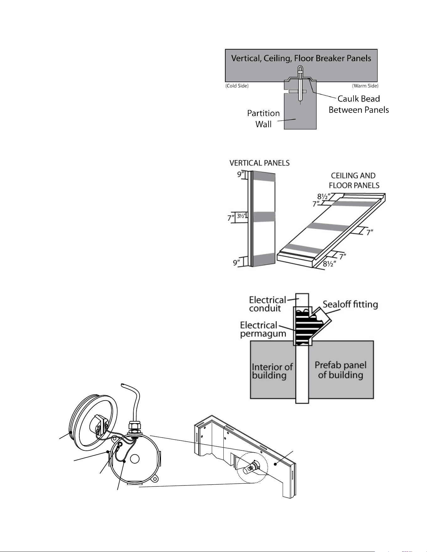
2. Partition Wall Caulking
As an added precaution against vapor leaks, Bally recommends
that all joints from partition wall panels to breaker panels (ver-
tical, ceiling, oor) be caulked on warm side during assembly.
See Figure 15.
3. Air gap/circulation recommendation.
Bally recommends a 2” gap between Walk-In vertical panels
and existing building walls for proper air circulation. It is also
recommended that air exchange/circulation be provided for
Walk-In s that are within an enclosed area.
4. Making holes for Refrigeration Tubing and Electrical
Lines
If penetrations in panels are needed, avoid the areas that are
shown. Penetrations should be made as needed by compe-
tent installer or mechanical service. If shaded areas are avoid-
ed, urethane insulation can be easily removed from opening.
After equipment installation, ll in hole with permagum caulk.
See Figure 16.
A. When a remote refrigeration system is used, it will be neces-
sary at the job site to make holes for refrigeration and electrical
lines.
B. After installation, use permagum to caulk around the electri-
cal and refrigeration lines. Caulk both the interior and exterior
gaps.
C. Condensation in electrical junction boxes is caused by warm
vapor passing from the exterior to the interior of the Walk-In
through electrical conduit lines. This problem can be elimi-
nated by installing a seal-o tting in the conduit line where it
passes through the wall. Install the tting as shown in Figure
17 and ll it with sealant.
5. Making electrical connections to Entrance Doors and
Installing Vapor-proof Lights
A. Electrical connections to the Walk-In doors are made at the
top interior of each door panel. See Figure 18. Remove the sock-
et plate to expose the wire connections in the junction box.
Cont. on page 8
Figure 15
Figure 16
Figure 17
Figure 18
GREEN WIRE
LIGHT
JUNCTION
BOX
GROUND
TERMINAL
LIGHT
BASE
DOOR
INTERIOR
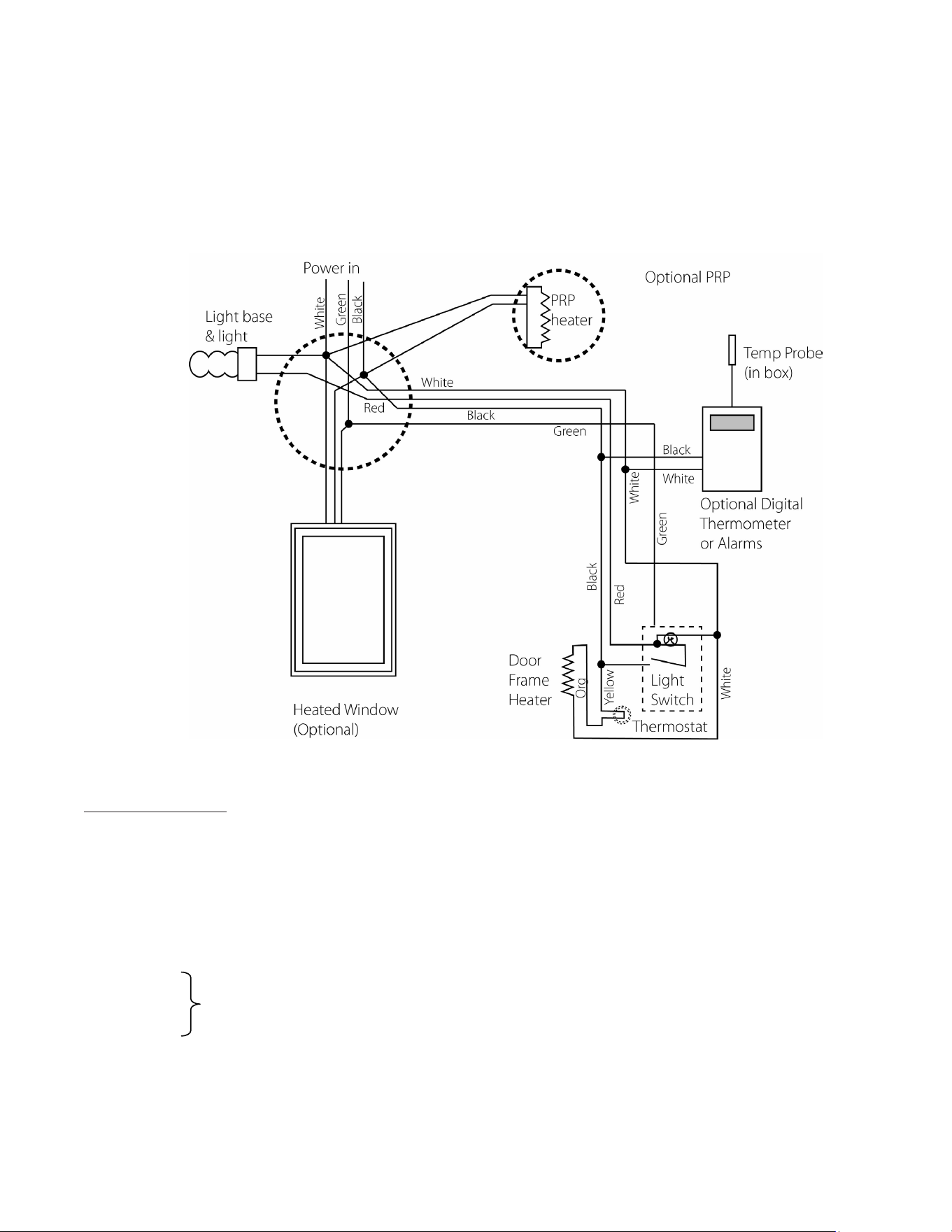
Color Codes:
Black – Line
White – Neutral
Green – Ground
Red – From switch to light
Orange – Wires for -3 and -4 way switches.
Grey – Connect like colors to complete the circuit.
UPDATED: 2/2019 Instruction Manual IM-268-11 2017© Bally Refrigerated Boxes, Inc. 8
Making electrical connections to Entrance Doors and Installing Vapor-proof Lights (Continued)
B. Remove the short wire “pigtails” and connect the service at the wire nuts, through the hole provided in the junction box. Refer
to serial tag for proper electrical characteristics. Insure that the electrical service is properly grounded. See Figure 19. Remount
the vapor-proof light assembly after all connections have been made. Do not turn on power to door section until after
the refrigeration system has been started.
Figure 19

UPDATED: 2/2019 Instruction Manual IM-268-11 2017© Bally Refrigerated Boxes, Inc. 9
Part Four: Completing the Bally Installation
A. Trim door wiper gasket (if necessary) from the inside bottom of door. The wiper gasket should gently touch the
threshold when the door is in the closed position. Adjust hinges and latch if necessary (shims provided in Miscel-
laneous Box #1)
B. After all locks are engaged, it is very important to secure the plug buttons over the Speed-Lok holes. (These buttons
are in Miscellaneous Box #1)
C. Make sure all of the protective plastic is removed from the panels and the job site debris is cleaned up.
D. Inform the electrician that he is now able to complete connections to door light and Pressure Relief Port (if on a
separate circuit) Please note that it is not recommended to hook up door heaters until the mechanical refrigeration
is fully operational. The heat will melt the door gasket.
E. After the installation is complete use a silicone caulk between the outside vertical panels and the concrete oor. If
large gaps exist, make certain to rst till the voids with expanding foam prior to sealing with caulk. Apply sealant to
building oor if water tight seal.
F. If installing an outdoor Bally Box with a membrane roof, make sure all the termination bars are securely fastened and
that all exterior joints have been caulked to prevent water leaks. All outdoor Walk-Ins must be protected against
the weather by a roof of some type, refer to “Instructions for Membrane Roof” to properly install. We can also supply
a standing seam aluminum roof where specied; Bally will provide separate installation instructions as needed for
these products.
G. You are now ready to hang evaporators and connect refrigeration. See separate instructions supplied by the manu-
facturer of the refrigeration’s mechanical equipment.
Bally Refrigerated Boxes, Inc.
1-800-24BALLY
[email protected] • www.ballywalkin.com
Phone: 252.240.2829 | Fax: 252.240.0258
135 Little Nine Drive, Morehead City, NC 28557
Installation Reference Information
Please Fill in the spaces below and retain this manual for easy reference.
Purchaser’s name and address: ________________________________________________________
Date Installed: _________________
Name of Installer: _______________________________ Installer’s Phone Number: _______________
Walk-In Serial Number (from plate above door): ___________________________________________
Refrigeration System Model Numbers: __________________________________________________
Refrigeration System Serial Numbers: ___________________________________________________
Notes:____________________________________________________________________________
_________________________________________________________________________________
_________________________________________________________________________________
_________________________________________________________________________________

