COMMERCIAL
AIR TO WATER
HEAT PUMP WATER HEATER
OWNERS GUIDE AND
INSTALLATION INSTRUCTIONS
This water heater must be installed and serviced by a qualified person.
Please leave this guide with a qualified professional.
ANSI/NSF-5
WATER QUALITY
C
L
A
S
S
I
F
I
E
D
AP22851 Rev 01

Commercial Air to Water Heat Pump Water Heater
2
TECHNICAL SUPPORT LINE
Rheem: 800-432-8373
Raypak: 805-278-5300
ORDER CENTER
Rheem: 1-800-621-5622
Raypak: 805-278-5300
RHEEM WATER HEATERS
800 Interstate Park Dr.
Montgomery, AL 36109
Website: www.Rheem.com
e-mail: T[email protected]
CONTENTS
INTRODUCTION ...............................................................................................................................3
SAFETY ............................................................................................................................................3
ABOUT YOUR WATER HEATER .....................................................................................................4
HOW YOUR WATER HEATER WORKS ..........................................................................................7
REGULAR CARE ..............................................................................................................................9
WATER SUPPLIES .........................................................................................................................11
SAVE A SERVICE CALL ................................................................................................................12
INSTALLATION ...............................................................................................................................14
HEAT PUMP AND TANK ASSEMBLY ...........................................................................................25
MANIFOLD INSTALLATIONS ........................................................................................................29
CONNECTIONS - PLUMBING .......................................................................................................31
CONNECTIONS ELECTRICAL ......................................................................................................33
CONTROLLER/DISPLAY ...............................................................................................................40
COMMISSIONING ...........................................................................................................................44
DRAINING THE WATER HEATER ................................................................................................54
TROUBLE SHOOTING ...................................................................................................................55
AUTOMATIC DEFROST .................................................................................................................56
WARRANTY .....................................................................................................................................57
Commercial Air to Water Heat Pump Water Heater
3
Only a licensed person will give you a Compliance Cer-
tificate, showing that the work complies with all the rel-
evant standards.
NOTE: The instructions in this manual are for the use
of qualified individuals specially trained and experi-
enced in the installation and maintenance of this type
equipment and related system components. Instal-
lation and service personnel are required by some
states to be licensed. Persons not qualified shall not
attempt to install, service, or maintain equipment.
Your safety and the safety of others are very impor-
tant. There are many important safety messages in this
manual and on your appliance. Always read and obey
all safety messages.
This is the safety alert symbol.
Recognize this symbol as an indication
o f Important Safety Information!
This symbol alerts you to potential hazards that
can kill or hurt you and others.
DANGER
WATER TEMPERATURE SETTING
Safety and energy conservation are factors to be con-
sidered when selecting the water temperature setting
of the water heater. Water temperatures above 125°F
(52°C) can cause severe burns or death from scalding.
DANGER: Occupied Spaces with small chil-
dren, disabled, or elderly persons may require a
120°F (49°C) or lower thermostat setting to pre-
vent contact with “HOT” water.
INTRODUCTION
SAFETY
DANGER
!
HOT
Water temperature over 125° F (52°C)
can cause severe burns instantly or
death from scalds.
Children, disabled and elderly are
at highest risk of being scalded.
See instruction manual before
setting temperature at water
heater.
Feel water before bathing or
showering.
Temperature limiting valves are
available, see manual.
BURN
Temperature Time To Produce a Serious Burn
120°F (49°C) More than 5 minutes
125°F (52°C) 1½ to 2 minutes
130°F (54°C) About 30 seconds
135°F (57°C) About 10 seconds
140°F (60°C) Less than 5 seconds
145°F (63°C) Less than 3 seconds
150°F (65°C) About 1½ seconds
155°F (68°C) About 1 second
Table courtesy of Shriners Burn Institute
!
4
Commercial Air to Water Heat Pump Water Heater
WATER HEATER APPLICATION
This water heater is designed for the purpose of heat-
ing potable water. Its use in an application other than
this may shorten its life.
HOW HOT SHOULD THE WATER BE?
The heat pump (compressor, evaporator and condens-
er) will operate until a water temperature of up to set-
point is reached.
The factory setting is 142°F (61°C). The setpoint can be
adjusted up to 149°F (65°C) depending on site suitabil-
ity after consulting with the manufacturer.
HOTTER WATER INCREASES THE RISK OF
SCALD INJURY
This water heater can deliver water at temperatures
which can cause scalding. Check the water tempera-
ture before use, such as when entering a shower or fill-
ing a bath or basin, to ensure it is suitable for the ap-
plication and will not cause scald injury.
We recommend and it may also be required by appli-
cable state or local regulations that an approved tem-
perature limiting device be fitted into the hot water
pipe work to the bathroom and ensuite when this water
heater is installed. This will keep the water temperature
below 122°F (50°C) at the bathroom and ensuite. The
risk of scald injury will be reduced and still allow hotter
water to the kitchen and laundry.
TEMPERATURE ADJUSTMENT
Setpoint Quick Setting
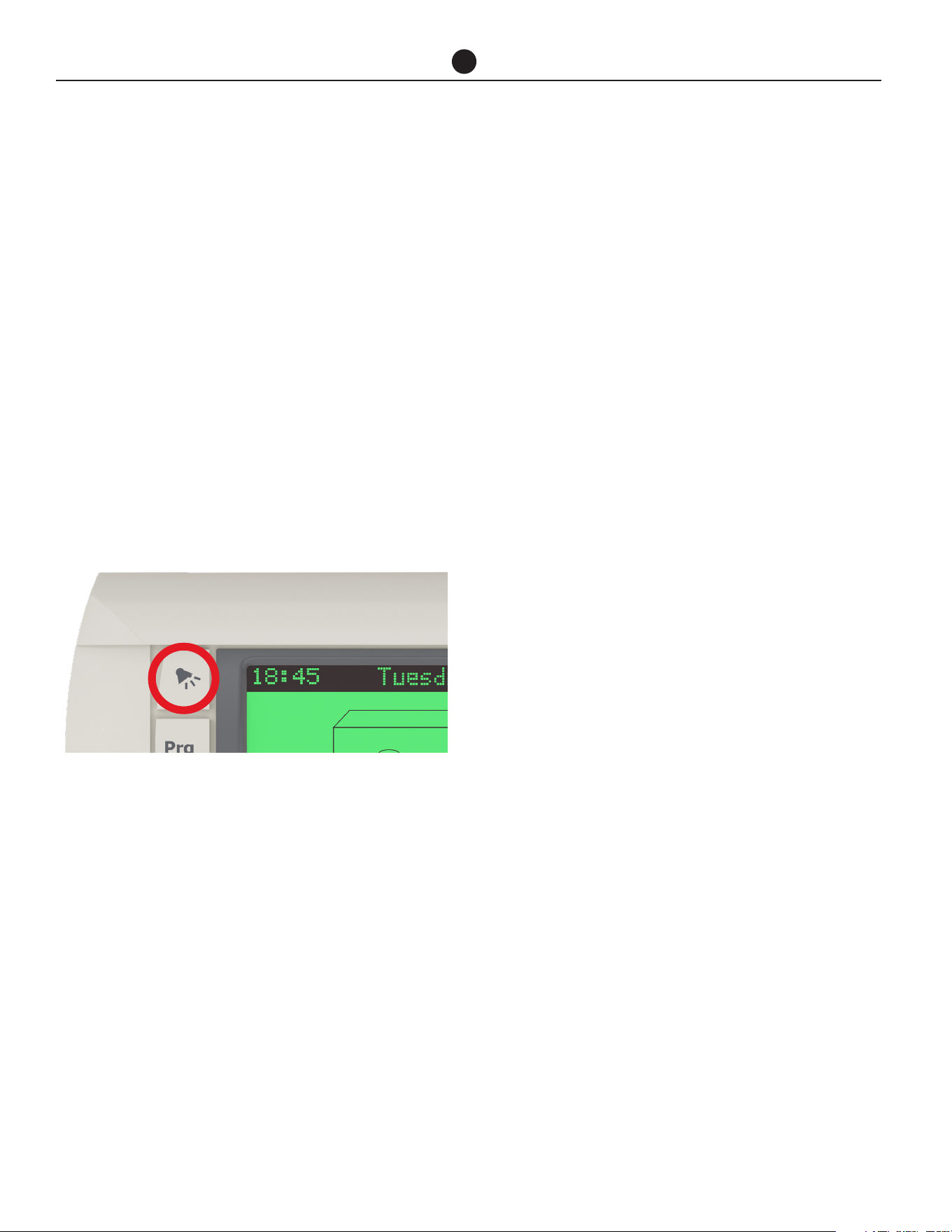
Press ‘prg’ from the main display screen and the Set-
point page will appear. Cursor will be on the set tem-
perature. Pressing the up and down keys will adjust the
setting in 0.1 increments. Hold down for rapid change.
Press ’Enter’ to confirm change. Press ‘esc’ to return to
the main display screen.
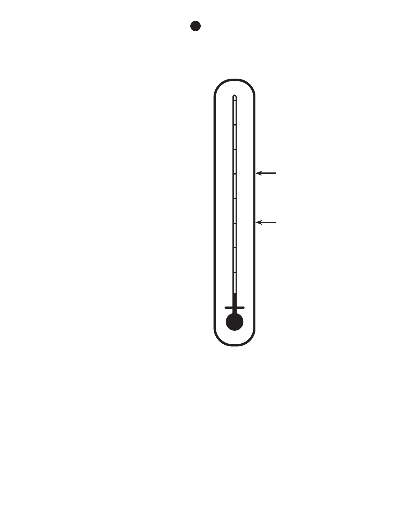
ABOUT YOUR WATER HEATER
95°F 35°C
104°F 40°C
113°F 45°C
122°F 50°C
131°F 55°C
140°F 60°C
149°F 65°C
158°F 70°C
167°F 75°C
Minimum recommended
stored water temperature
Maximum recommended
supply temperature to bath-
room and ensuites
NOTE: Mixing valves are required if adjusted above
120°F (49°C) for reducing point of use water tempera-
ture by mixing hot and cold water in branch water lines.
It is recommended that a mixing valve complying with
the Standard for Temperature Actuated Mixing Valves
for Hot Water Distribution Systems, ASSE 1017 be in-
stalled. See pages 15 & 17 for more details and contact
a licensed plumber or the local plumbing authority for
further information.

Commercial Air to Water Heat Pump Water Heater
5
WARNING: This water heater is only intended
to be operated by persons who have the experi-
ence or the knowledge and the capabilities to do
so. This water heater is not intended to be oper-
ated by persons with reduced physical, sensory or
mental capabilities i.e. the infirm, or by children.
Children should be supervised to ensure they do
not interfere with the water heater.
This water heater uses 208-240 or 480 VAC electrical pow-
er for operation of the control systems and other electri-
cally operated components. The removal of the access
cover(s) will expose 208-240 or 480 VAC wiring. They must
only be removed by a qualified person.
• DO NOT use aerosols, stain removers and chemi-
cals near the water heater. Gases from some aerosol
sprays, stain removers and chemicals are corrosive to
the materials used in the heat pump system.
• DO NOT store swimming pool chemicals, household
or industrial cleaners, etc., near the water heater.
• Ensure the air inlet and outlet ports and air flow are
not obstructed in any way at any time.
SAFETY
This water heater is supplied with built in Controller which
controls low and high pressure switches, low temperature
cut off, temperature safety switch and flow switch.
Additionally, the compressor is fitted with thermal over-
load protection, the condenser heat exchanger is fitted
with a pressure relief valve, the heat pump is supplied with
a built in ambient temperature sensor. These devices must
not be tampered with or removed. The water heater must
not be operated unless each of these devices is fitted and
is in working order.
If the electrical supply conduit to the water heater is dam-
aged, it must be replaced by a qualified person in order to
avoid a hazard. Contact your local service contractor to
arrange for an inspection.
WARNING: For continued safety of this water
heater it must be installed, operated and main-
tained in accordance with the Owner’s Guide
and Installation Instructions.
WARNING! FLAMMABLE CONTENTS UNDER
PRESSURE.. The compressor wiring terminals
may arc allowing pressurized refrigerant and
oil to escape, ignite and cause serious bodily
injury, severe burns or death.
The warranty may not cover faults if relief
valves or other safety devices are tampered
with or if the installation is not in accordance
with these instructions.
TO TURN OFF THE WATER
HEATER
• Switch off the electrical supply at the circuit break-
er to the water heater.
• Close the isolation valves at the inlet and outlet of
the water heater.
TO TURN ON THE WATER
HEATER
• First, ensure the water is connected to storage
tanks, the system is filled with water and all valves
between the tanks and the water heater are open.
• Switch on the electrical supply at the circuit break-
er to the water heater.
NOTE: The water heater may not turn on immediately
when it is first switched on, if it is switched on within
20 minutes to 2 hours of it having been switched off at
the circuit breaker, or the heat pump has just com-
pleted a heating cycle. The water heater will wait until
the conditions for start-up are favorable in order to
protect the compressor from damage. This may take
up to 20 minutes to 2 hours.
HOW DO I KNOW IF THE
WATER HEATER IS INSTALLED
CORRECTLY?
Installation requirements are shown on the "Installa-
tion" section. The water heater must be installed:
• by a qualified person, and
• in accordance with the installation instructions, and
• in compliance with Standards UL 1995, NSF/ANSI/
CAN 61 and all local codes and regulatory authority
requirements.
ABOUT YOUR WATER HEATER

Commercial Air to Water Heat Pump Water Heater
6
DOES THE WATER CHEMISTRY
AFFECT THE WATER HEATER?
The water heater is suitable for most public water sup-
plies, however some water chemistries may have detri-
mental effects on the water heater, its components and
fittings. Refer to “Water Supplies” section. If you are
not sure, have your water chemistry checked against
the conditions described on the "Chloride and PH" and
"Summary of Water Chemistry Advice Affecting the
Warranty" sections.
CAUTIONS
Where damage to property can occur in the event of
the water heater leaking, the water heater must be in-
stalled in a safe tray or be suitably bounded.
The water heater must be maintained in accordance
with the Owner’s Guide and Installation Instructions.
Refer to “Regular Care” section.
If this water heater is to be used where an uninterrupt-
ed hot water supply is necessary for your application,
or business you should ensure that you have back up
redundancy within the hot water system design. This
should ensure the continuity of hot water supply in the
event that this water heater were to become inoperable
for any reason. We recommend you seek advice from
your plumber, specifier or Rheem Application Engineer
about your needs and building back up redundancy
into your hot water supply system.
ENVIRONMENT
At the end of the service life of the water heater and
prior to the water heater being disposed of, a person
qualified to work with refrigerants must recover the re-
frigerant from within the sealed system. The refrigerant
must not be vented to atmosphere. Contact your local
service contractor to arrange for an inspection.
ABOUT YOUR WATER HEATER

Commercial Air to Water Heat Pump Water Heater
7
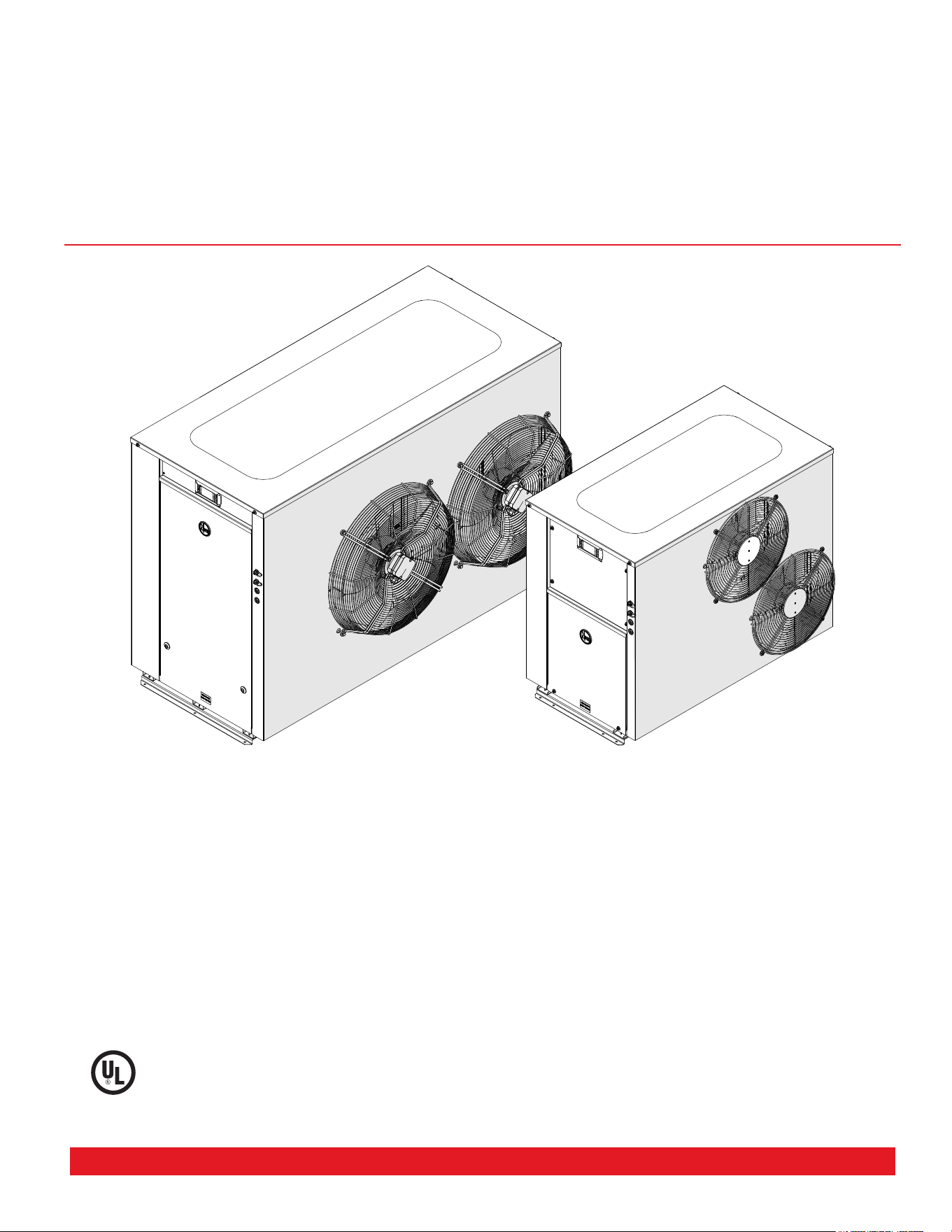
HOW YOUR WATER HEATER WORKS
The commercial heat pump is an instantaneous type
and does not have an integral storage tank. The unit
is designed to be installed indoors or outdoors, mod-
el dependent. The water heater’s evaporator absorbs
heat from the surrounding air and transfers this heat
into the water. A circulator transfers the heated water
to a bank of storage tanks. The heat pump produces a
sound level of up to 69 dBA (measured at 9.8 ft) when it
is operating. The principle of operation and sound level
are similar to that of an air conditioner.
When hot water is drawn off and cold water enters the
storage tanks, a remote thermostat activates the fan,
compressor and circulating pump of the water heater.
Air is drawn in through the inlet louvers on the side of
the water heater and then past the evaporator, where
heat is transferred from the air to a refrigerant fluid. The
fluid is compressed and passes to the condenser (heat
exchanger) where heat is transferred into the water.
The pump circulates water from the bottom of the stor-
age tanks through the heat exchanger and the heated
water is circulated back into the storage tanks. The fan
discharges the cooled air through the fan grilles on the
top of the water heater. This process continues until the
water in the storage tanks reaches the set temperature.
Even on cold days, heat is drawn from the surrounding
air. The heat pump will operate most efficiently at tem-
peratures between a minimum of 41°F (5°C) and maxi-
mum of 113°F (45°C). The efficiency of the water heater
is relative to the surrounding air temperature and the
incoming water temperature.
Automatic safety controls are fitted to the water heater
to provide safe and efficient operation.
AUXILIARY BOOST OPERATION
The water heater can control an auxiliary heating source
if the ambient temperature falls below 41°F (5°C) or if
50% or more of the water heaters are in fault mode.
OPERATION AT LOW AMBIENT
TEMPERATURE
Ice may begin to form on the evaporator when the am-
bient air temperature falls below 45°F (7°C), and this
will reduce the heat pump efficiency. In this case, the
heat pump will use hot gas bypass to de-ice the evapo-
rator coil. Should the ambient temperature continue to
fall below 41°F (5°C), the heat pump will enter Low Am-
bient mode. The water heating system can be designed
to operate in one of two scenarios when ambient tem-
perature falls below 41°F (5°C).
When auxiliary heating mode is OFF, the heat pump will
use hot gas bypass to melt any ice that may form on
the evaporator coil when operating at air temperatures
below 41°F (5°C) and there will be no auxiliary boost.
When auxiliary heating mode is ON, the heat pump will
use hot gas bypass to melt any ice that may form on
the evaporator coil when operating at air temperatures
below 41°F (5°C) and auxiliary gas or electric water
heater will be activated. Auxiliary heater will remain ac-
tive until the air temperature reaches 45°F (7°C).
OPERATION IN FAULT MODE
If fitted, the auxiliary booster will operate instead of the
heat pump if the heat pump is in fault.
For multiple heat pump (Primary/Secondary) configu-
ration, the auxiliary booster will operate instead of the
heat pumps if fifty percent (50%) or more heat pumps
are in fault.
The auxiliary boost will operate until the set tempera-
ture is reached. The auxiliary boost should be set to
140°F (60°C).
The auxiliary boost will remain active until the water
heater fault is cleared.
WARNING: Rheem nor its subsidiaries will
not be responsible for higher utility bills due to
excessive use of auxiliary boost heater. It is the
customers’ responsibly to monitor the system
regularly for its correct operation. We recom-
mend monitoring via BMS (modules supplied
separately).
MAINS PRESSURE
The water heater is designed to operate at mains pres-
sure by connecting directly to the mains water supply.
If the mains supply pressure in your area exceeds, a
pressure limiting valve must be fitted.
Commercial Air to Water Heat Pump Water Heater
8
THERMAL CUTOUT
The refrigeration circuit is protected by thermal sen-
sors. These will activate a thermal cut out in the event
of excessive heat in the refrigeration system.
If the thermal cut out has activated, the heat pump will
not operate for a period of 20 minutes to 2 hours. The
water heater will make two more attempts to start up.
If the thermal cut out is tripped again after the third
attempt, the system will enter lock out and the alarm
contacts will close. If connected to a BMS, this will alert
the user that the unit is not operating.
The lockout condition can be manually reset by switch-
ing the power to the water heater off and then on.
CONTROL FUNCTIONALITY
A timer can be set through the heat pump control panel
to limit the hours of operation of the water heater (e.g.
to reduce noise at night).
The operation of the heat pump can also be controlled
by setting up tariff option on the control panel to man-
age operating costs.
NOTE: depending on the booster configuration
there may be insufficient stored energy avail-
able for the next peak period if the system is
not up to temperature.
Remember, even on cloudy and cold days your heat
pump water heater will heat your stored water.
SUPERIOR MONITORING
The Heat Pump System is supplied with 9 sensors:
1. Tank temperature sensor
2. Building flow temperature sensor
3. Water inlet temperature sensor
4. Water outlet temperature sensor
5. Refrigerant suction side temperature (superheat)
6. Suction pressure transducer
7. Discharge pressure transducer
8. Ambient air temperature sensor
9. Evaporator coil sensor
The output of these sensors are displayed on the user
friendly control panel to ensure correct system opera-
tion.
HOW YOUR WATER HEATER WORKS
The system can be connected to BMS via interface cards (Modbus RS485 or BACnet MS-TP or BACnet TCP/IP Ethernet) supplied. Contact us for
further information on BMS.
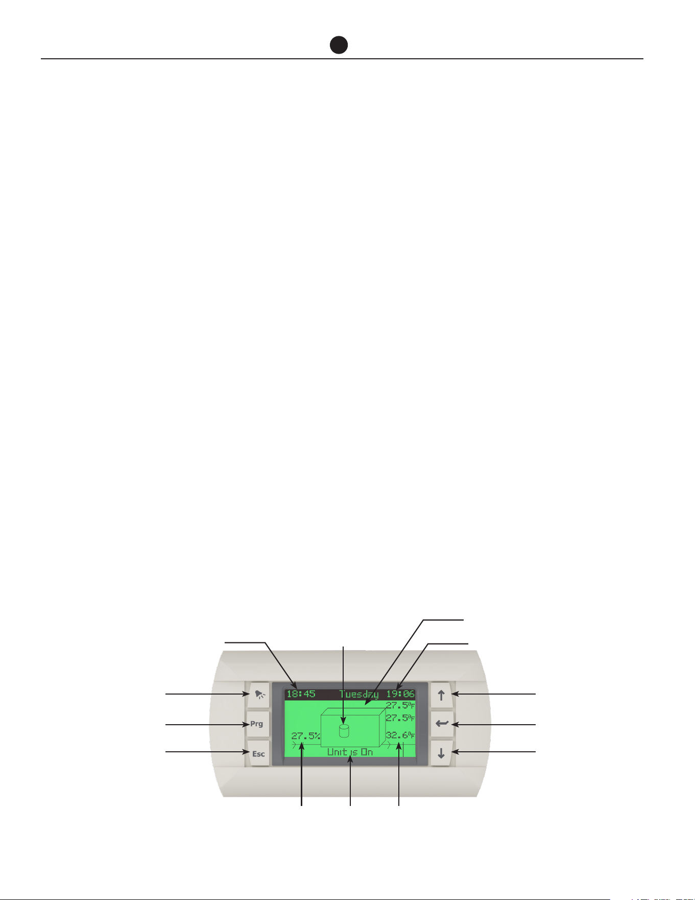
Up Button
Outside Ambient Temperature
Day & Date
Outside
Ctrl1:
Ctrl1: Controlling
Sensor (Tank)
Compressor
Function Indicator
Time (24 Hour)
Alarm Button
Enter ButtonPrg Button
Down ButtonEsc Button
Hot Water
Leaving Temp
On/Off
Indicator
Hot Water
Entering Temp

Commercial Air to Water Heat Pump Water Heater
9
REGULAR CARE
It is suggested that the commercial heat pump be serviced annually, to retain optimum performance. Servicing must
be performed by a suitably qualified person.
ANNUAL SERVICE
1. Check the sensors are fully installed into thermal
wells.
2. Check for leaks at all fittings.
3. Check for signs of excessive corrosion on storage
tank(s) jacket(s) and heat pump casing.
4. Check for sludge build up and if necessary drain
and flush storage tank(s).
5. Clear hot water pump impeller and ensure free ro-
tation.
6. Check condensate drain for blockages – clear if
necessary.
7. Clean blockages and debris from evaporator fins,
fan blades and grilles.
8. Isolate power to heat pump and check all electrical
connections for signs of overheating due to poor
connection.
9. Check for vibration or excessive noise from com-
pressor, fans and hot water pump.
10. Check refrigerant pressures and adjust refrigerant
charge if required.
11. Visually check system for any potential problems.
12. Confirm correct system operation.
13. Operate temperature and pressure relief valve and
expansion control valve. Refer to next page.
FIVE YEAR SERVICE
1. As per annual service.
2. Inspect and if required, replace storage tank(s)
anode(s). If the anode is not replaced, it should be
replaced within three years of this service.
3. Check operation of defrost solenoid valve by man-
ually operating the valve.
4. Replace temperature and pressure relief valve or
expansion control valve.
Refer to Service manual for more information.

Commercial Air to Water Heat Pump Water Heater
10
REGULAR CARE
TEMPERATURE AND PRESSURE
RELIEF VALVE EXPANSION
CONTROL VALVE AND
EXPANSION TANK
A temperature and pressure relief valve should be used
with the storage tanks. In many areas, an expansion
control valve or expansion control tank is also fitted to
the cold water line to the water heater system. The ex-
pansion control valve may discharge a small quantity
of water from its drain line during the heating period
instead of the temperature pressure relief valve on the
storage tanks.
Operate the easing lever on the temperature and pres-
sure relief valve and expansion control valve. It is very
important you raise and lower the lever gently.
WARNING: Exercise care to avoid any splash-
ing of water, as water discharged from the drain
line will be hot. Stand clear of the drain line’s
point of discharge when operating the valve’s
lever.
If water does not flow freely from the drain line when the
lever is lifted, then the water heater must be checked
contact a local service technician to arrange for an in-
spection.
The temperature and pressure relief and expansion
control valve or expansion control tank should be re-
placed at intervals not exceeding 5 years, or more fre-
quently in areas where there is a high incidence of wa-
ter deposits (refer to “Water Supplies” section).

Commercial Air to Water Heat Pump Water Heater
11
WATER SUPPLIES
This water heater must be installed in accor-
dance with this advice to be covered by the
warranty.
This water heater is manufactured to suit the water
conditions of most public reticulated water supplies.
However, there are some known water chemistries
which can have detrimental effects on the water heater
and its operation and / or life expectancy. If you are
unsure of your water chemistry, you may be able to ob-
tain information from your local water supply authority.
This water heater should only be connected to a water
supply which complies with these guidelines for the
Rheem’s warranty to apply.
CHANGE OF WATER SUPPLY
The changing or alternating from one water supply to
another can have a detrimental effect on the operation
and/or life expectation of a number of components in
this water heater.
Where there is a changeover from one water supply to
another, e.g. a rainwater tank supply, bore water sup-
ply, desalinated water supply, public reticulated water
supply or water brought in from another supply, then
water chemistry information should be sought from the
supplier or it should be tested to ensure the water sup-
ply meets the requirements given in these guidelines
for the warranty to apply.
SATURATION INDEX
The saturation index (SI) is used as a measure of the
water’s corrosive or scaling properties.
Where the saturation index is less than –1.0, the water
is very corrosive and the warranty does not apply to the
water heater. In a corrosive water supply, the water can
attack copper parts and cause them to fail.
Where the saturation index exceeds +0.40, the water is
very scaling and an expansion control valve* must be
fitted on the cold water line after the non-return valve.
The warranty does not apply to the water heater.
Water which is scaling may be treated with a water
softening device to reduce the saturation index of the
water.
CHLORIDE AND PH
Where the chloride level exceeds the warranty does
not apply to the water heater. In a high chloride water
supply, the water can corrode stainless steel parts and
cause them to fail.
Where the pH is less the warranty does not apply to
the water heater. pH is a measure of whether the water
is alkaline or acid. In an acidic water supply, the water
can attack stainless steel parts and cause them to fail.
Water with a pH less than 6.0 may be treated to raise
the pH. The water supply from a rainwater tank in a
metropolitan area is likely to be corrosive due to the
atmospheric contaminants.
SUMMARY OF WATER
CHEMISTRY ADVICE AFFECTING
THE WARRANTY
The water heater is not suitable for certain water chem-
istries. Those chemistries are listed below. If the water
heater is connected at any time to a water supply with
the following water chemistry, Rheem's warranty will
not cover any resultant
WATER CHEMISTRY HEAT PUMP
WATER TEMPERATURE 40°F - 150°F
pH <6PPM
CHLORIDES <149 mg/l
IRON <0.35 mg/l
COPPER <0.10 mg/l
TDS <705 mg/l
HARDNESS <260 PPM
Commercial Air to Water Heat Pump Water Heater
12
SAVE A SERVICE CALL
Check the items below before making a service call.
You will be charged for attending to any condition or
fault that is not related to manufacture or failure of a
part.
NOT ENOUGH HOT WATER (OR
NO HOT WATER)
• Is the electricity switched on?
Inspect the circuit breaker marked “HOT WATER”
or “WATER HEATER” at the electrical service panel
and the isolating switch at the water heater and en-
sure they are turned on.
Check the circuit breaker marked “HOT WATER” or
“WATER HEATER” at the electrical service panel.
• Is the alarm light flashing RED on heat pump
controller?
If the alarm light is flashing RED, check the alarm
by pressing the alarm button. Contact your nearest
Service Department to inform about the alarm.
• Is the timer set?
If the timer has been set, ensure sufficient time has
been allowed to reheat the storage tanks.
• Are you using more hot water than you
think?
Are outlets (especially the showers) using more hot
water than you think? Very often it is not realised
the amount of hot water used, particularly when
showering. Carefully review the hot water usage.
Have your plumber install a flow control valve to
each shower outlet to reduce water usage.
• Heat pump circulator has failed?
The heat pump will not operate if the heat pump
circulator has failed. Refer to “Heat Pump Is Not
Operating” section . Phone your nearest Service
Department or Accredited Service Agent to arrange
for an inspection.
• Water heater size
Do you have the correct size water heater for your
requirements? Contact Rheem Application Engi-
neering for guidance.
• Air temperature is cold – defrost mode
If this method of low ambient temperature opera-
tion is used, the heat pump will enter a defrost
mode when ice is sensed on the evaporator coil.
The recovery rate of the heat pump is reduced in
this mode due to the lower operating air tempera-
ture and heating of water is reduced during the de-
frost cycle.
WATER TOO HOT
The water heater, during both normal heat pump opera-
tion and auxiliary booster operation (activated during
periods of ambient temperatures below 41°F (5°C) or
heat pump fault), will heat the water to a temperature of
140°F (60°C) to 149°F (65°C). It is recommended to set
the auxiliary booster thermostat setting to 140°F (60°C).
WATER NOT HOT ENOUGH
You may find that due to heavy hot water usage the wa-
ter temperature may be lower than normally expected,
due to insufficient heating time being allowed. Addi-
tional storage or an in series booster may be required
to be installed under these circumstances.

Commercial Air to Water Heat Pump Water Heater
13
HEAT PUMP IS NOT OPERATING
• Ambient temperature is cold– auxiliary boost
mode
If this method of low ambient temperature opera-
tion is used the heat pump may not operate when
the ambient temperature is below 41°F (5°C) and
the auxiliary water heater, if installed, will operate
instead. The total storage tank capacity will be
heated to 140°F (60°C) during these periods. Aux-
iliary boost will turn OFF and heat pump will start
operating as normal when air temperature increas-
es to 45°F (7°C) or higher.
• Thermal cut out activated
Has the thermal cut out for the heat pump com-
pressor activated?
If the thermal cut out has activated, the heat pump
will not operate for a period of 20 minutes to 2 hours
and display alarm on the control panel. The water
heater will make two more attempts to start. If the
thermal cut out is tripped again after the third at-
tempt, the system will enter lock out. If connected
to a BMS, this will alert the user that the unit is not
operating.
To check whether there may be a problem, switch
the power to the water heater off and on again at
the circuit breaker to the water heater, then open a
hot tap and allow to run for ten to fifteen minutes.
The heat pump, if working properly, will activate
and continue operating to heat the water. Close the
hot tap when the heat pump begins to operate.
However, if the heat pump deactivates within five
minutes, there may be a problem. Contact your
nearest service technician.
• Incorrect Phase Rotation
The phase fail relay will open circuit if the heat
pump has been wired with incorrect phase rota-
tion or if a phase has failed. Both green and yellow
LEDs on the relay will be illuminated if all phases
are available and phase rotation is correct.
• Heat pump circulator has failed
If the heat pump circulator has failed, the heat
pump will not operate and may trip on a fault. Con-
tact your local service technician to arrange for an
inspection.
HIGH ELECTRICITY BILLS
With the installation of your new air sourced heat pump
water heater, maximum electrical energy savings can
be achieved. Should you at any time, feel your energy
account is too high, we suggest you check the follow-
ing points:
Is the relief valve in the storage tanks running exces-
sively?
• Are outlets (especially the showers) using more hot
water than you think? (Refer to “Not Enough Hot
Water” on previous page).
• Is there a leaking hot water pipe, dripping hot water
tap, etc? Even a small leak will waste a surprising
quantity of hot water and energy. Replace faulty tap
washers, and have your plumber rectify any leaking
pipe work.
• Consider recent changes to your hot water usage
pattern and check if there has been any increase in
tariffs since your previous account.
• The heat pump water heater operates at its most
efficient at higher air temperatures. Prolonged pe-
riods of low ambient temperature will decrease
the efficiency of the system and increase running
costs.
IF YOU HAVE CHECKED ALL THE FOREGOING
AND STILL BELIEVE YOU NEED ASSISTANCE,
CONTACT YOUR LOCAL SERVICE TECHNICIAN.
SAVE A SERVICE CALL

Commercial Air to Water Heat Pump Water Heater
14
THIS WATER HEATER IS FOR INDOOR OR OUT-
DOOR INSTALLATION, MODEL DEPENDENT.
THIS WATER HEATER IS NOT SUITABLE FOR
POOL HEATING.
INSTALLATION STANDARDS
The water heater must be installed:
• by a qualified person, and
• in accordance with the installation instructions, and
• in compliance with Standards UL 1995, NSF/ANSI/
CAN 61 and all local codes and regulatory authority
requirements.
WATER HEATER APPLICATION
This water heater is designed for the purpose of heating
potable water. Its use in an application other than this may
shorten its life
If this water heater is to be used where an uninterrupted
hot water supply is necessary for the application or busi-
ness, then there should be redundancy within the hot wa-
ter system design. This should ensure the continuity of
hot water supply in the event that this water heater was
to become inoperable for any reason. We recommend you
provide advice to the system owner about their needs and
building backup redundancy into the hot water supply
system.
COMPONENTS
The heat pump water heater system is modular and com-
prises three main components: the heat pump water
heater, storage tanks and primary circulator. An auxiliary
booster and/or circulator may also be employed as part of
the system. The water heater must not be operated until
all components are assembled.
DO NOT tilt the heat pump more than 45° from
the vertical. This will unsettle the refrigerant gas and
compressor lubricating oil. If the heat pump has been
tilted more than 45° from the vertical during handling, it
will need one hour to settle before the power to the water
heater can be switched on, otherwise damage to the
compressor may result.
INDOOR INSTALLATION
To comply with UL 1995, the minimum room size per-
missible in relation to the quantity of refrigerant in the
water heater, is 264.86ft
3
per 60k BTUh heat pump and
626.12ft
3
per 135k BTUh heat pump. A larger room size
is recommended for efficient heat pump operation.
WATER HEATER LOCATION
Non ducted vertical and horizontal models are designed
to be installed outdoors or indoors, if a sufficient supply
of heat energy is available and the room meets the vol-
ume requirements stated above. Good performance is
obtained when the heat pump is supplied with a constant
supply of fresh air. Failure to observe the above recom-
mendations may lead to lower than expected perfor-
mance or problematic operation of the heat pump.
Vertical and horizontal models can be converted with a
kit, models are designed for ducting of discharge air in
indoor installations.
The water heater should be installed close to the storage
tanks and its position chosen with noise, safety and ser-
vice in mind. Make sure the air inlet and outlet grilles are
clear of obstructions and shrubbery and they are unlikely
to be touched by people (especially children).
It is advisable to install the water heater away from bed-
room or living room windows as the system can generate
a noise of 69dBA (at 10ft from the water heater) whilst
operating.
It is recommended the water heater be installed at ground
or floor level. Stacked units with base unit at ground or
floor level is acceptable from a servicing perspective.
The water heater must stand vertically upright.
NOTE: to assist with condensate drainage, the
heat pump has a 2.5 degrees slope towards the
drains. Do not level the product.
Clearance must be allowed for servicing of the water
heater. The water heater must be accessible without the
use of a ladder or scaffold.
You must be able to read the information on the rating
plate. Remember you may have to remove the entire wa-
ter heater later for servicing.
The water heater must not be installed in an area with
a corrosive atmosphere where chemicals are stored or
where aerosol propellants are released. Remember the
air may be safe to breathe, but the chemicals may attack
the materials used in the heat pump system.
INSTALLATION
Commercial Air to Water Heat Pump Water Heater
15
INSTALLATION
SAFE TRAY
Where damage to property can occur in the event of the
water heater leaking or condensate forming under the
drain tray, the water heater must be installed in a safe tray
or be suitably bounded. Construction, installation and
draining of a safe tray must comply with all local codes
and regulatory authority requirements.
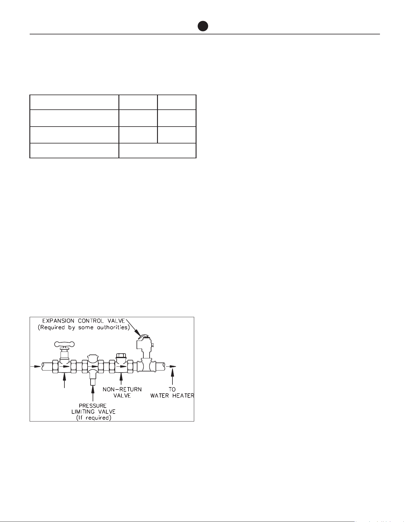
MAINS WATER SUPPLY
Where the mains water supply pressure exceeds that
shown in the table below, an approved pressure limiting
valve is required and should be fitted as shown in the in-
stallation diagram.
TANK WATER SUPPLY
If the storage tank is supplied with water from a tank sup-
ply and a pressure pump system is not installed, then the
bottom of the supply tank must be at least 3.2 ft above
the highest point of the hot water plumbing system, in-
cluding the storage tank. Care must be taken to avoid air
locks. The cold water line to the storage tank should be
adequately sized and fitted with a full flow gate valve or
ball valve.
HOT WATER DELIVERY
This water heater can deliver water at temperatures which
can cause scalding.
It is necessary and we recommend that a temperature lim-
iting device be fitted between the storage tanks and the
hot water outlets in any ablution area such as a bathroom
or ensuite, to reduce the risk of scalding. The installing
plumber may have a legal obligation to ensure the instal-
lation of this water heater system meets the delivery water
temperature requirements of UL 1995 so that scalding wa-
ter temperatures are not delivered to a bathroom, ensuite
or other ablution area.
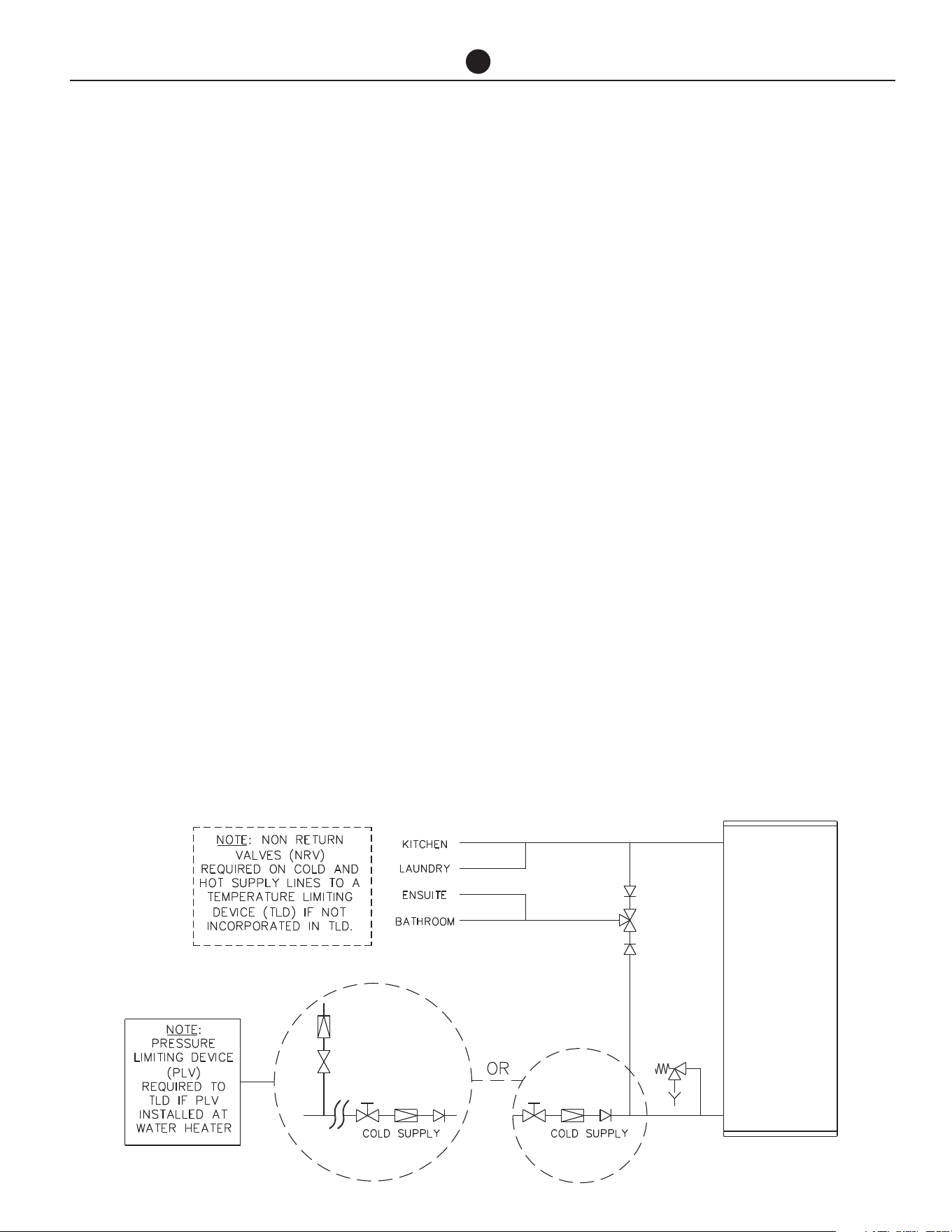
Where a temperature limiting device is installed adjacent
to the storage tanks, the cold water line to the tempera-
ture limiting device can be branched off the cold water
line either before or after the ball valve, pressure limiting
valve and non return valve to the water heater system. If
an expansion control valve is required, it must always be
installed after the non return valve and be the last valve
prior to the storage tanks.
If a pressure limiting valve is installed on the cold water
line to the water heater system and the cold water line
to a temperature limiting device branches off before this
valve or from another cold water line in the premises, then
a pressure limiting valve of an equal pressure setting may
be required prior to the temperature limiting device.
Two Temperature Zones Using a Temperature Limiting Device

Commercial Air to Water Heat Pump Water Heater
16
INSTALLATION
CIRCULATED HOT WATER FLOW
AND RETURN SYSTEM
This heat pump water heater may be installed as part of
a circulated hot water flow and return system in a build-
ing as long as a temperature boosting water heater is
not installed downstream of the heat pump.
If a temperature boosting water heater is installed the
circulated hot water flow and return system must return
to the inlet of the temperature boosting water heater,
and not the heat pump, to avoid potential nuisance
tripping. Refer to the diagram on page 18.
Temperature Limiting Device
A temperature limiting device cannot be installed in cir-
culated hot water flow and return pipe work unless the
device is designed for this application. The tempered
water from a temperature limiting device cannot be cir-
culated. Where a circulated hot water flow and return
system is required in a building, a temperature limiting
device can only be installed on a dead leg, branching
off the circulated hot water flow and return pipe.
If circulated tempered water were to be returned back
to the water heater, depending on the location of the
return line connection on the water supply line to the
water heater, then either:
• water will be supplied to the cold water inlet of the
temperature limiting device at a temperature exceed-
ing the maximum recommended water supply tem-
perature, or
• when the hot taps are closed no water will be sup-
plied to the cold water inlet of the temperature limiting
device whilst hot water will continue to be supplied to
the hot water inlet of the temperature limiting device.
These conditions may result in either water at a tem-
perature exceeding the requirements of UL 1995 being
delivered to the hot water outlets in the ablution areas,
or the device closing completely and not delivering wa-
ter at all, or the device failing. Under either condition,
the operation and performance of the device cannot be
guaranteed.
INSULATION
To minimise heat loss and provide protection from
freezing, the cold water line to and the hot water line
from the heat pump water heater must be insulated in
accordance with the requirements of UL 1995. The in-
sulation must be weatherproof and UV resistant if ex-
posed.
SADDLING - PIPE WORK
To prevent damage to the heat pump and storage tanks
when attaching pipe clips or saddles to the water heat-
er jacket, we recommend the use of self-drilling screws
with a maximum length of 0.5 in (12 mm). Should pre
drilling be required, extreme caution must be observed
when penetrating the jacket of the water heater.
Avoid drilling or saddling in the vicinity of the
evaporator coil. The coil and refrigerant circuit
are in close proximity to the jacket and ruptur-
ing of the refrigerant circuit may occur.
Note: If the heat pump is damaged as a result
of attaching pipe clips or saddling to the jacket,
any resultant faults will not be covered by the
warranty.
Commercial Air to Water Heat Pump Water Heater
17
INSTALLATION
Commercial Air to Water Heat Pump Water Heater
18
INSTALLATION
Commercial Air to Water Heat Pump Water Heater
19
INSTALLATION
Commercial Air to Water Heat Pump Water Heater
20
INSTALLATION
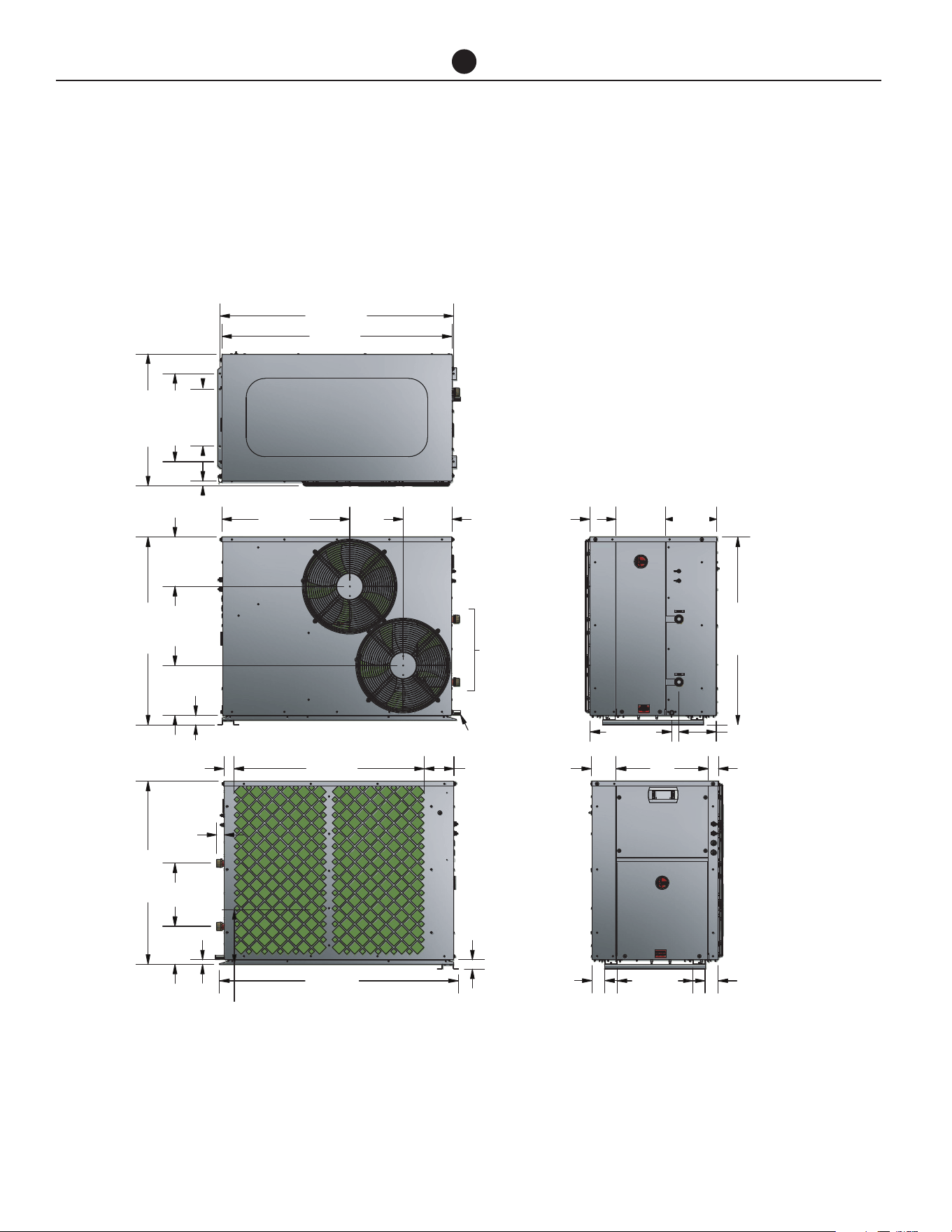
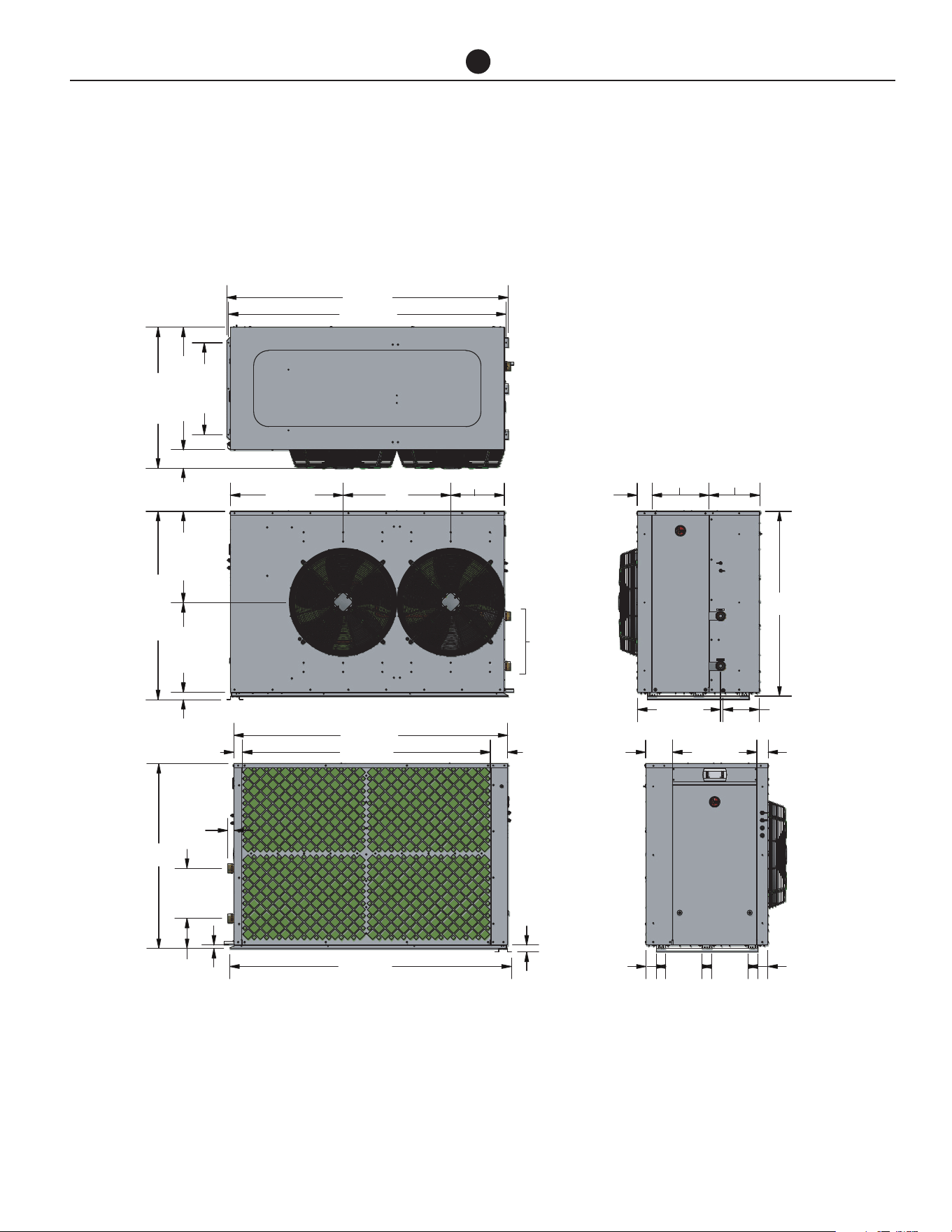
DIMENSIONS AND TECHNICAL DATA- 60K BTU MODELS
A2W 60k BTU- Ducted Horizontal Discharge HPHD-60HNU-201
HPHD-60HNU-201 (Horizontal)
TOP VIEW
SIDE VIEW
SIDE VIEW
END VIEW
END VIEW
FAN
ACCESS
WATER
OUTLET
WATER
INLET
ELEC.
ACCESS
COPM.
ACCESS
WATER
CONNECTIONS
1-1/4” NPT
CONDENSATE
DRAIN Ø 13/16”
1
48-3/16
47-1/2
11-13/16
18-3/16
27-3/16
36-3/8
10-1/8
10-1/4
38-3/4
1
10-3/8
1-5/8
37-3/4
39-1/4
13
1-15/16
2-1/8
6-1/8
1-15/16
49-1/4
11-5/16
7-7/8
5-1/2
10-3/16
10-5/8
38-3/4
7-11/16
2-1/8
195-1/8
2-11/16
15-5/8
2-11/16
16-7/8
Commercial Air to Water Heat Pump Water Heater
21
INSTALLATION
DIMENSIONS AND TECHNICAL DATA- 60K BTU MODELS
A2W 60k BTU - Vertical Discharge HPHD-60VNU-201
48-3/16
47-1/2
19-11/16
16-1/2
9-3/4
11-13/16
18-3/16
26-3/16
10-1/8
17-11/16
1-1/16
36-13/16
39-13/16
TOP VIEW
SIDE VIEW
SIDE VIEW
END VIEW
END VIEW
1-15/16
39-1/4
49-1/4
1-5/8
2-1/8
1-15/16
1
7-7/8
13
38-13/16
WATER
CONNECTIONS
1-1/4” NPT
CONDENSATE
DRAIN Ø 13/16”
FAN
ACCESS
WATER
OUTLET
WATER
INLET
6-1/8
ELEC.
ACCESS
COPM.
ACCESS
5-9/16
11-3/4
8-15/16
38-3/4
7-13/16
2-3/4
2-1/8
195-1/8
2-11/16 2-11/16
15-11/16
Commercial Air to Water Heat Pump Water Heater
22
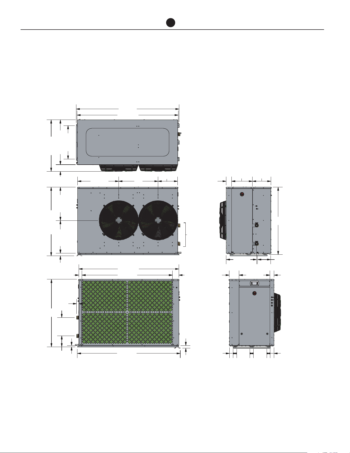
DIMENSIONS AND TECHNICAL DATA- 135K BTU MODELS
RHEEM A2W 135 K BTU - Horizontal Discharge HPHD-135HNU-483
INSTALLATION
2-5/82-5/8
9-7/16 9-7/16
4
9
1
2
2
28
COPM.
ACCESS
WATER
CONNECTIONS
2” NPT
TOP VIEW
SIDE VIEW
SIDE VIEW
END VIEW
END VIEW
FAN
ACCESS
WATER
OUTLET
WATER
INLET
73-1/8
72-1/16
23-7/8
31-13/16
36-5/8
71-1/16
64-3/8
1-7/8
73-1/8
4-9/16
2-1/4
1-5/8
13
7-7/8
1
48-15/16
23-3/423-1/4
29-1/4
13-15/16
48
48
3-7/8
14-13/16 13-3/16
3
21-7/8
7
21-5/8
9-5/16
Commercial Air to Water Heat Pump Water Heater
23
DIMENSIONS AND TECHNICAL DATA- 135K BTU MODELS
RHEEM A2W 135 K BTU - HPHD-135VNU-483
INSTALLATION
2-5/82-5/8
9-7/16 9-7/16
4
9
1
2
2
28
COPM.
ACCESS
WATER
CONNECTIONS
2” NPT
TOP VIEW
SIDE VIEW
SIDE VIEW
END VIEW
END VIEW
FAN
ACCESS
WATER
OUTLET
WATER
INLET
73-1/8
72-1/16
23-7/8
31-13/16
36-5/8
71-1/16
64-3/8
1-7/8
73-1/8
4-9/16
2-1/4
1-5/8
13
7-7/8
1
48-15/16
23-3/423-1/4
29-1/4
13-15/16
48
48
3-7/8
14-13/16 13-3/16
3
21-7/8
7
21-5/8
9-5/16

Commercial Air to Water Heat Pump Water Heater
24
SIDES 60K BTU MODELS 135K BTU MODELS
Evap Coil Side 20 in (500 mm) 40 in (1000 mm)
Back (vertical discharge models) Nil Nil
Back (horizontal discharge models) 47 in (1200 mm) 78 in (2000 mm)
Display Side 34 in (850 mm) 34 in (850 mm)
Water Connections Side 20 in (500 mm) 24 in (600 mm)
Top (vertical discharge models) 47 in (1200 mm) 79 in (2000 mm)
Top (horizontal discharge option) Clearance above unit required for service personnel to stand.
CLEARANCES- AIR TO WATER HEAT PUMP MODELS
INSTALLATION
NOTE: 40 inches between evaporation coils when side by side.

Commercial Air to Water Heat Pump Water Heater
25
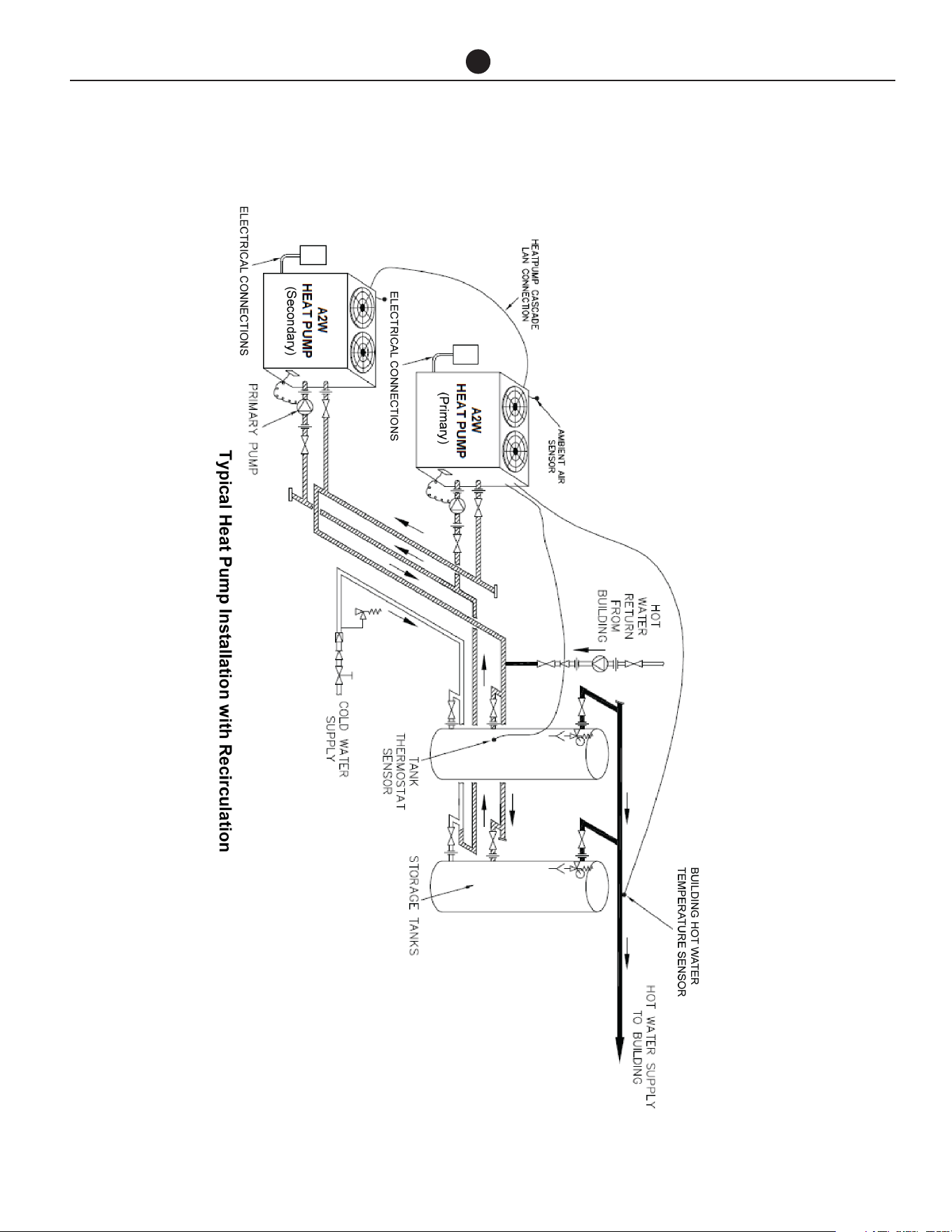
HEAT PUMP AND TANK ASSEMBLY
HEAT PUMP AND STORAGE
TANKS
The heat pump water heater system is modular and
comprises three main components: the heat pump wa-
ter heater, storage tanks and primary circulator. An aux-
iliary booster and/or circulator may also be employed
as part of the system. The water heater must not be
operated until all components are assembled.
HEAT PUMP
Locate the heat pump(s) in the appropriate position ob-
serving the required clearances for operation and ser-
vicing. Refer to previous page.
Indoor Installations
To comply with UL 1995, the minimum room size per-
missible in relation to the quantity of refrigerant in the
water heater, is 264.9 ft
3
per HPHD-60, 60k Btuh heat
pump and 626.1 ft
3
per HPHD-135, 135k Btuh heat
pump. A larger room size is recommended for efficient
heat pump operation.
Good performance is obtained when the heat pump
is supplied with a constant supply of fresh air. Failure
to observe the above recommendations may lead to
lower than expected performance or problematic op-
eration of the heat pump.
Ventilation
The heat pump draws fresh air at a rate of 56.5 ft
3
/s
for HPHD-60, heat pump and 204.8 ft
3
/s for HPHD-135,
heat pump. Minimum recommended free air inlet venti-
lation opening is 10.8 ft
2
per HPHD-60, heat pump and
20.8 ft
2
per HPHD-135, heat pump.
Ducted Models with Kit
The maximum static pressure in the ductwork must not
exceed the values states in the table below:
Horizontal Ducting
If ducting horizontally, the vertical dimension of the
duct must be at least 31.5 in high. It is recommended
to terminate the ducting with bird mesh as this pro-
vides the least pressure resistance to the fans against
air flow. If louvres are to be used, the duct size must be
increased. The duct should have a slight fall away from
the heat pump and the terminal face be tapered down-
wards to prevent water ingress.
Vertical Ducting
If ducting vertically, the duct must terminate 19.68 in
above the roof level and have a free ventilation outlet
area equivalent to 10.76 ft
2
per heat pump 60k BTU
models and 20.77ft
2
per 135k BTU heat pump mod-
els. It is recommended to terminate the duct with bird
mesh as this provides the least pressure resistance to
the fans against air flow. Adequate weather protection
must be provided to prevent water ingress.
Horizontal Fan Option
If a horizontal discharge fan option has been select-
ed, the same rules apply to location of installation. If
installed indoors, observe the same requirements as
shown in indoor installations on page 14.
MAXIMUM STATIC PRESSURE
HPHD-60 HEAT PUMP HPHD-135 HEAT PUMP
0.08 in WC 0.08 in WC
Commercial Air to Water Heat Pump Water Heater
26
HEAT PUMP AND TANK ASSEMBLY
STORAGE TANKS
Commercial storage tanks are employed to store the
hot water generated by the heat pump. The tanks must
be manifolded to ensure even distribution of the stored
energy. More than one bank can be used. Follow the
Manifold Arrangement diagram in this Manual when
manifolding the tanks.
Refer to the installation instructions supplied with the
storage tanks for specific information relating to the in-
stallation of the storage tanks.
PRIMARY CIRCULATOR
Each heat pump requires a primary circulator to ensure
the correct flow rate and temperature rise is achieved.
Where more than one heat pump is installed the com-
mon manifold system must be sized to accommodate
the total flow of all the primary pumps running simulta-
neously.
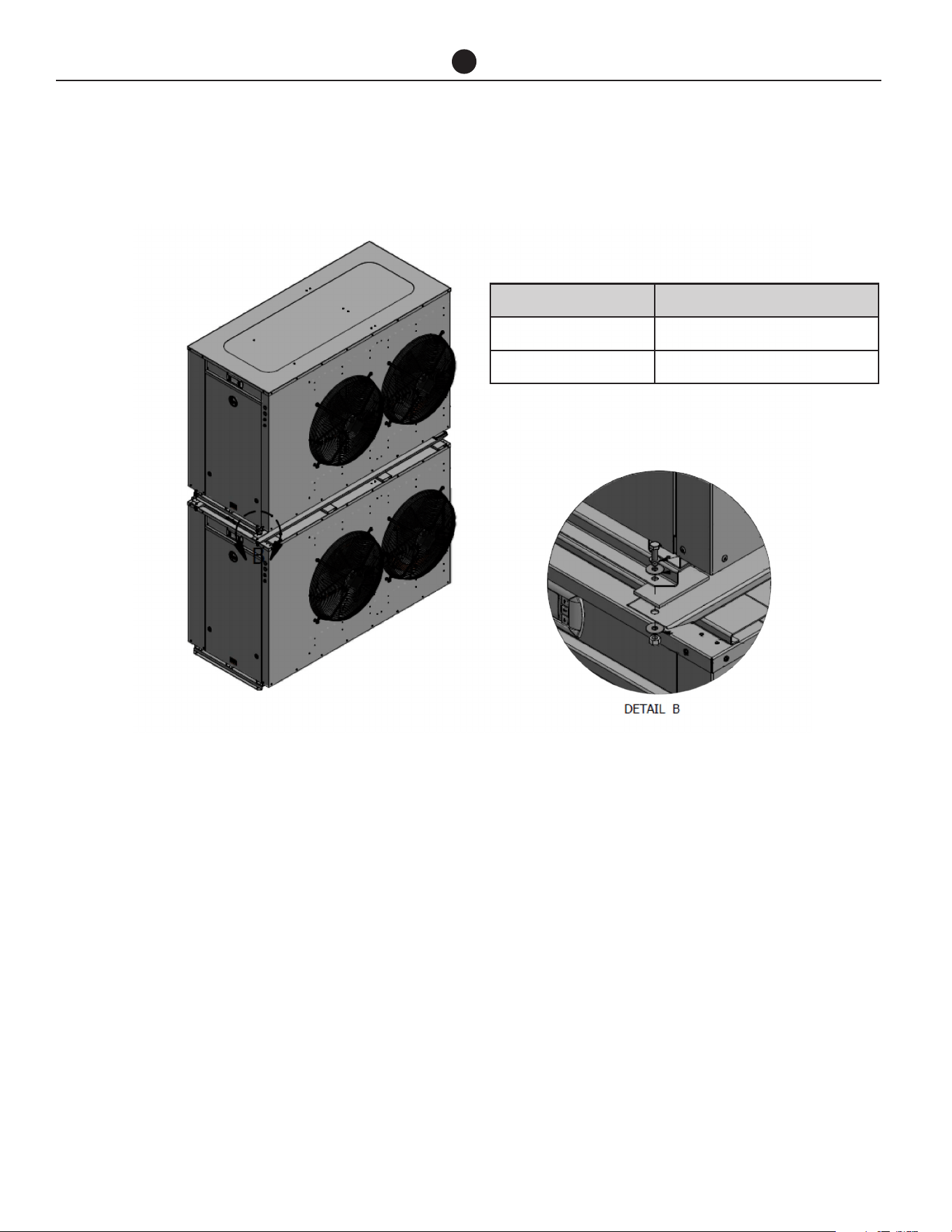
Staking kits available for horizontally vented
heaters. See Kit Instillation Instructions for
proper stacking
PART NUMBER DESCRIPTION
45263 HPHD-60 Horizontal Stacking Kit
45264 HPHD-135 Horizontal Stacking Kit
Commercial Air to Water Heat Pump Water Heater
27
HEAT PUMP AND TANK ASSEMBLY
Refer to table below for minimum (ID) pipe sizing.
The designed primary pump per 60k Btuh model is Grundfos model CM3-2 and per 135k Btuh model is CM10-1.
Refer to installation manuals supplied with pumps. If another pump has been supplied, consult Rheem before con-
tinuing with the installation.
60K BTUH
No. of Heat Pumps in Parallel 1 2 3 4
Pump
Grundfos CM3-2
(Rheem AP22760A)
Branch Size (in) 1.5"
Header Size (in) 1.5" 2" 2.5" 3"
135K BTUH
No. of Heat Pumps in Parallel 1 2 3 4
Pump
Grundfos CM10-1
(Rheem AP22760B)
Branch Size (in) 2"
Header Size (in) 2" 3" 4" 4"
Header pipe sizing is based on one pump per heat
pump with a total length of 65 ft of primary flow and
return piping and 20 x 90° bends, excluding manifolds
on storage tanks and heat pumps, at 3.9 ft/sec velocity.
If this specification is exceeded consult Rheem before
continuing with the installation.
Multiple heat pumps MUST be installed to ensure equal
demand on each heat pump (or storage tank) in the
bank is the same as any other. To achieve this, the fol-
lowing is necessary:
1. The inlet manifolds must be designed to balance
the flow to each heat pump i.e. each branch line
must be the same diameter and length.
2. The outlet manifold must be designed to balance
the flow from each heat pump i.e. each branch line
must be the same diameter and length.
3. The first heat pump in must be the last heat pump
out.
NOTE: Inlet and outlet water isolation valves MUST
be installed at each heat pump to enable each heat
pump to be individually isolated for servicing. The inlet
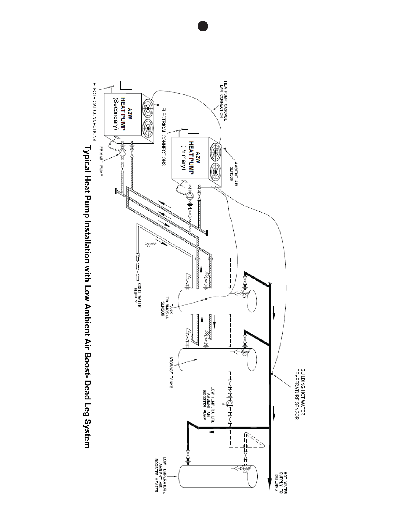
isolation valve MUST be installed before the pump to
also enable the pump to be isolated for servicing.
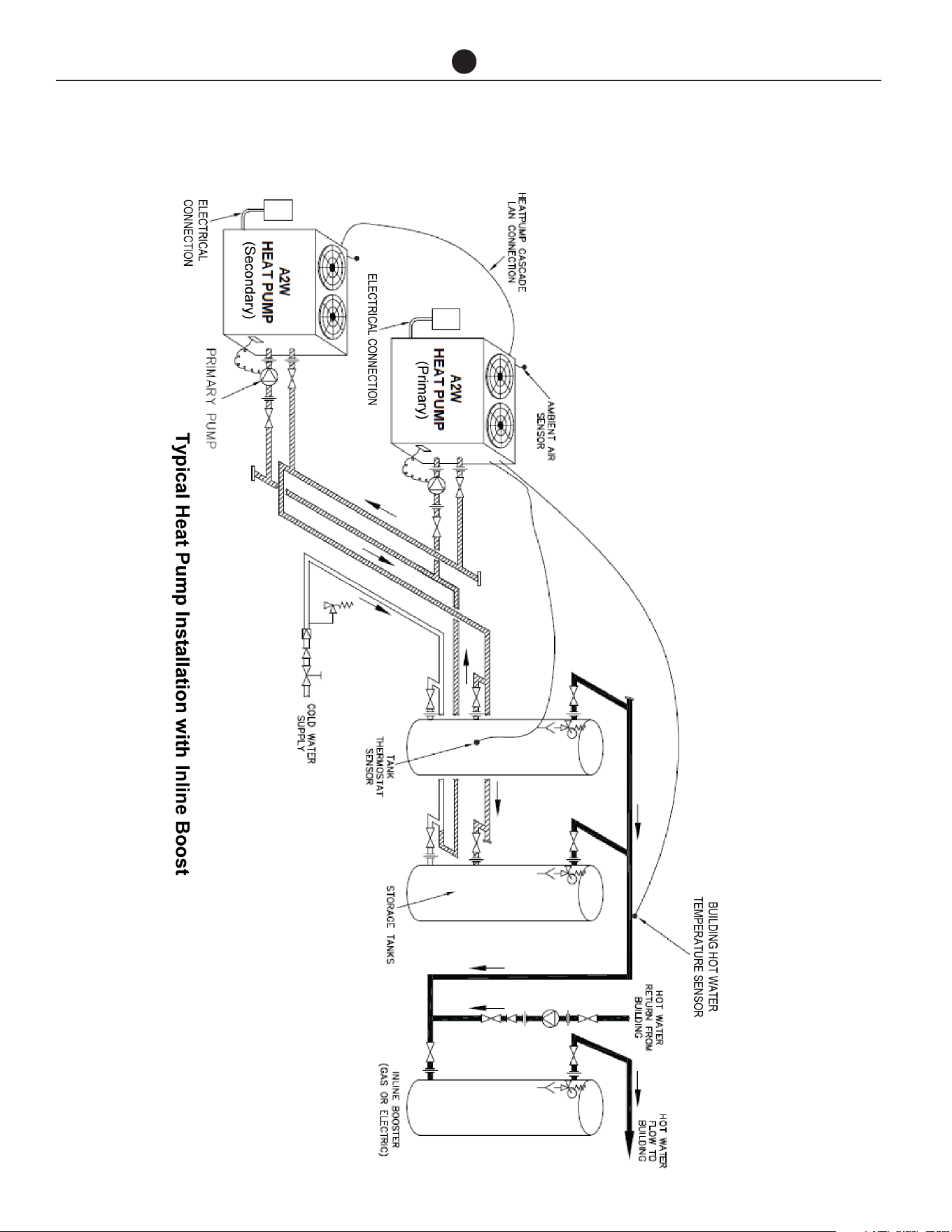
AUXILIARY WATER HEATER
It may be necessary to install an auxiliary water heater
under the following conditions:
• If the ambient temperature is likely to drop below
41°F (5°C) during periods when heating may be re-
quired.
• To ensure sufficient hot water is available for higher
than expected peak conditions.
• If higher temperature water is required for certain
applications, e.g. commercial laundry or kitchen.

Commercial Air to Water Heat Pump Water Heater
28
HEAT PUMP AND TANK ASSEMBLY
The configuration of the auxiliary water heating plant
can vary depending on the requirements of the indi-
vidual installation.
Low Ambient Temperature Heating Only - Where
the auxiliary water heater is required to be activated if
the heat pump cannot operate due to low ambient con-
ditions, the heat pump can activate the auxiliary heater
or pump. There are many configurations depending on
system design. Refer to Application Guide for details
on the auxiliary boost function designed for this sys-
tem.
In Line Boosting Only - Where the auxiliary water
heater is required to ensure sufficient hot water is avail-
able for periods after the main peak or to boost the
temperature of the water produced by the heat pump
for other purposes (eg high temperature for kitchen and
laundry use), an auxiliary water heater must be installed
in series with the storage tanks. ie, the hot water outlet
from the storage tanks must feed into the inlet of the
auxiliary water heater(s).
NOTE: Where storage tanks are used, boosting in the
top portion of the storage tank is equivalent to boost-
ing in series.
Where multiple auxiliary water heaters are required to
be manifolded together, these must be manifolded. Re-
fer to next page.
This arrangement can also be adapted to include recir-
culation heat loss make up and / or low ambient tem-
perature activation heating. Refer to Application Guide
for options.
Commercial Air to Water Heat Pump Water Heater
29
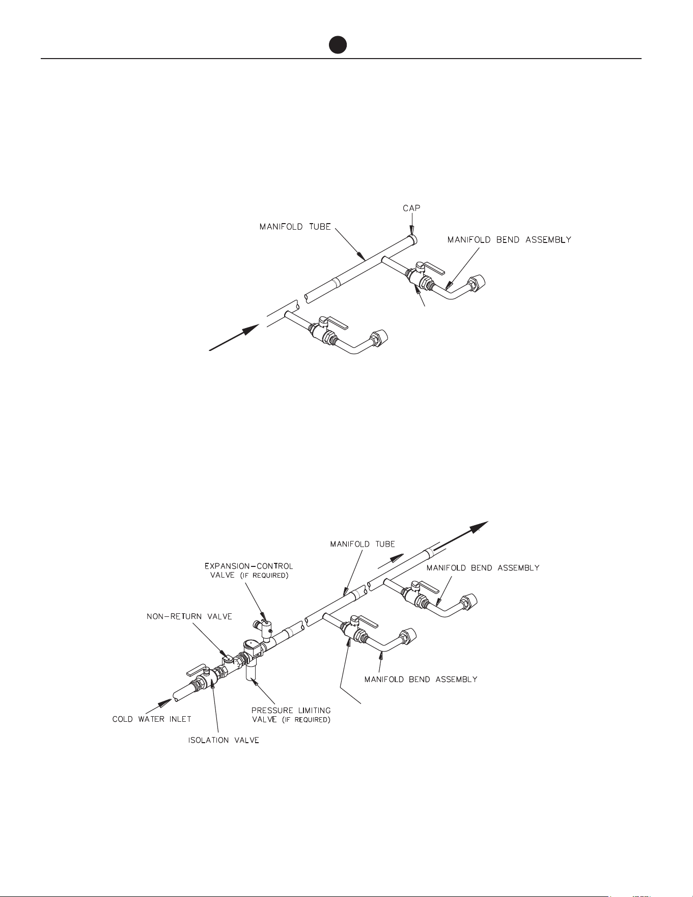
MANIFOLD INSTALLATIONS
The commercial heat pump water heater is designed
to be installed with storage tanks on a single manifold
or multiple manifolds if required. The cold water, pri-
mary flow and hot water manifolds must be designed
to balance the flow from each water heater and stor-
age tank. To achieve this, there are basic installation
requirements and principles which must be followed:
1. The maximum number of storage tanks in a bank
should be 10, however several banks of storage
tanks can be installed.
2. The hot water line from the manifold must leave
from the opposite end to which the cold water line
enters the manifold.
3. The storage tanks must be of the same model.
4. The cold water line, cold and hot headers and hot
water line must be sized to meet the requirements
of both AS/NZS 3500.4 and the application.
5. A non-return valve, isolation valve and if required
a pressure limiting valve and expansion control
valve, must be installed on the cold water line to
the system.
6. A full flow gate valve or ball valve (not a stop tap, as
used on a single water heater installation) must be
installed on both the cold water branch and hot wa-
ter branch of each water heater and storage tank.
7. Non return valves or pressure limiting valves MUST
NOT be installed on the branch lines to the water
heaters or storage tanks.
8. All fittings, valves and branch lines must be
matched sets all the way along the manifold.
9. Sufficient space must be left to enable access, ser-
vicing or removal of any water heater or storage
tank.
10. The temperature pressure relief valve drain line
from each storage tank can terminate at a com-
mon tundish (funnel) with a visible air break at each
drain discharge point.
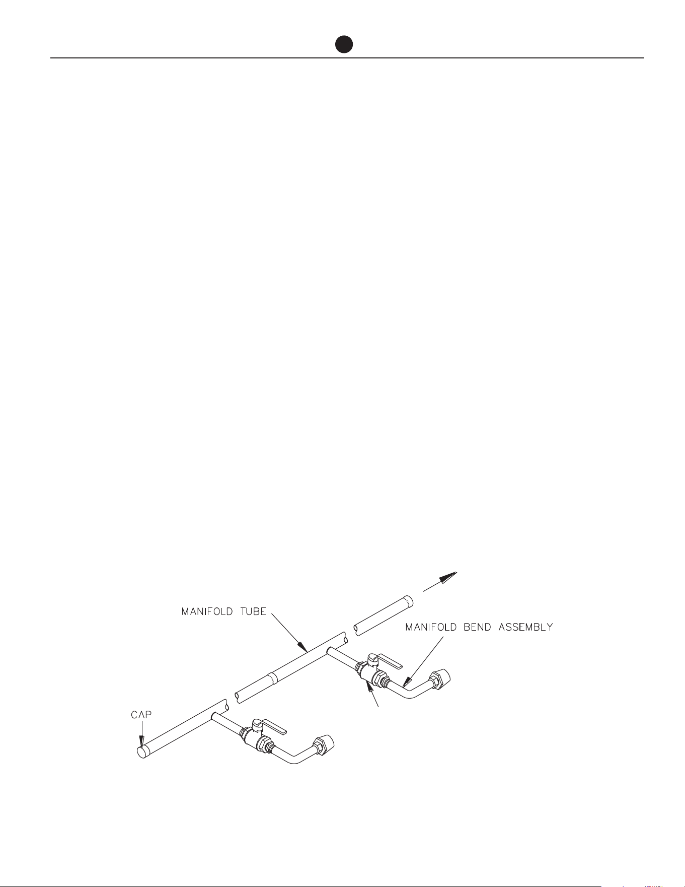
HOT WATER FLOW
AUTHORIZED BALL OR FULL FLOW
OR GATE VALVE
MANIFOLD ARRANGEMENT
Hot Manifold Assembly
Commercial Air to Water Heat Pump Water Heater
30
FLOW FROM
HEAT PUMPS
AUTHORIZED BALL OR FULL
FLOW OR GATE VALVE
RETURN TO
HEAT PUMPS
AUTHORIZED BALL OR FULL FLOW
OR GATE VALVE
MANIFOLD INSTALLATIONS
Primary Hot Water Flow
Manifold Assembly
Cold Manifold Assembly
Commercial Air to Water Heat Pump Water Heater
31
CONNECTION SIZES
All plumbing work must be carried out by a qualified
person and in accordance with the UL 1995.
WATER INLET AND OUTLET
The pipe work must be cleared of foreign matter before
connection and purged before attempting to operate
the water heater. All olive compression fittings must
use brass. Use thread sealing tape or approved thread
sealant on all screwed fittings.
An isolation valve and non-return valve must be in-
stalled on the cold water line to the water heater sys-
tem. An acceptable arrangement is shown in the dia-
gram. Refer also to “Hot Water Delivery” and to “Mains
Water Supply” sections in this Manual.
Disconnection unions are provided at the cold water
inlet and hot water outlet on the water heater to allow
for disconnection of the water heater.
PIPE SIZES
To achieve true mains pressure operation, the cold wa-
ter line to the storage tanks should be the same size or
bigger than the hot water line from the storage tanks.
The pipe sizing for hot water supply systems should
be carried out by persons competent to do so, choos-
ing the most suitable pipe size for each individual ap-
plication. Reference to the technical specifications of
the water heater and local regulatory authority require-
ments must be made.
Refer to the table on the left for correct primary flow
and return pipe sizing.
RELIEF VALVE
The heat pump is supplied with an integral pressure re-
lief valve located on the inside of the heat pump cabi-
net and will discharge into the tray of the heat pump.
Refer to Condensate Drain on next page for drainage
instructions.
EXPANSION CONTROL VALVE
Local regulations may make it mandatory to install an
expansion control valve (ECV) in the cold water line
to the water heater system. In other areas, an ECV is
not required unless the saturation index is greater than
+0.4 (refer to “Water Supplies” on page 11). However,
an ECV may be needed in a corrosive water area where
there are sufficient quantities of silica dissolved in the
water.
The expansion control valve must always be installed
after the non return valve and be the last valve installed
prior to the water heater system (refer to diagram on
page 38).
CONNECTIONS - PLUMBING
Model 60k BTU 135k BTU
Heat pump water heater inlet
connection
1¼" NPT 2" NPT
Heat pump water heater outlet
connection
1¼ NPT 2" NPT
Condensate drain connection
13/16"
Ball Valve
Ball Valve

Commercial Air to Water Heat Pump Water Heater
32
CONNECTIONS - PLUMBING
EXPANSION CONTROL VALVE
DRAIN
A copper drain line must be fitted to the relief valve to
carry the discharge clear of the water heater. Connect
the drain line to the relief valve using a disconnection
union. The pipe work from the relief valve to the drain
should be as short as possible and fall all the way from
the water heater with no restrictions. It should have no
more than three right angle bends in it. Use NPT 1/2
pipe.
The outlet of the drain line must be in such a position
that flow out of the pipe can be easily seen (refer to UL
1995) - but arranged so hot water discharge will not
cause injury, damage or nuisance. The drain line must
discharge at an outlet or air break not more than 19.52
ft from the relief valve.
In locations where water pipes are prone to freezing,
the drain line must be insulated and not exceed 12" in
length. The drain line must be installed in accordance
with local codes.
CONDENSATE DRAIN
A drain line must be fitted to the condensate drains to
carry the discharge clear of the water heater. The drain
line can be extended using 13/16 in O.D. rigid hose or
conduit. Where installed externally, the drain line pipe
work must be UV resistant or protected from sunlight.
The outlet of the drain line must be in such a position
that flow out of the pipe can be easily seen - but ar-
ranged so water discharge will not cause damage or
nuisance. The water heater is supplied with fall and t is
recommended to install the water heater with a slight
fall towards the condensate drain.
The condensate drain must not be connected to the
pressure relief or expansion control valve drain line but
may discharge at the same point.
Commercial Air to Water Heat Pump Water Heater
33
CONNECTIONS - ELECTRICAL
The power supply to the water heater must not be
switched on until the water heater is filled with water
and a satisfactory megger reading is obtained.
MEGGER READING
When a megger test is conducted on this water heater,
then the following should be noted.
WARNING: This water heater contains elec-
tronic equipment and 500 V insulation tests
must only be conducted between actives and
earth and between neutral and earth. An active
to neutral test WILL damage the electronics.
An insulation test result of above 1 MΩ should be ob-
tained for this water heater.
ELECTRICAL CONNECTION
All electrical work and permanent wiring must be
carried out by a qualified person and in accordance
with UL 1995.
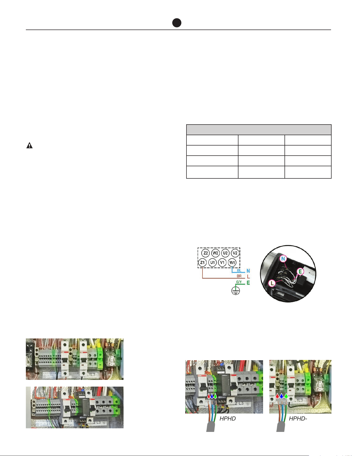
HEAT PUMP
The heat pump water heater must be directly con-
nected to the proper mains power supply (HPHD-60
at 208-240V single phase, HPHD135 at 480V 3 phase).
The heat pump must be on its own circuit with an cir-
cuit breaker installed at the switchboard. A secondary
isolating switch must be installed within reach of the
water heater.
A conduit is required for the electrical cable to the heat
pump water heater. The conduit is to be connected to
the unit with a 20mm terminator. Holes are provided
on the electrical panel for cabling. Connect the power
supply and earth wires directly to the terminal block,
ensuring there are no excess wire loops inside the elec-
trical enclosure. Correct phase connection is required.
PRIMARY PUMP
The power to the primary pump for each heat pump is
supplied from the water heater. Connect the hot lines,
neutral and earth wire to the pump terminals as shown
in the photo inside the pump cover and to the terminals
located within the heat pump electrical enclosure.
A 0.750" conduit pipe is required for the electrical cable
between the water heater and pump. The conduit is to
be connected to the water heater with a 0.750" termi-
nator.
Holes are provided on the electrical panel for cabling.
ELECTRICAL DATA TABLE
Model 60k Btu 135k Btu
Electrical Connection 208-240V single phase 480V (3 phase)
MCA 40 A 35A
Minimum Circuit Size
(per phase)
60A 50A
Photo inside the pump cover.
HPHD-60
HPHD-60
HPHD135
HPHD135
Primary Pump
Primary Pump
Commercial Air to Water Heat Pump Water Heater
34
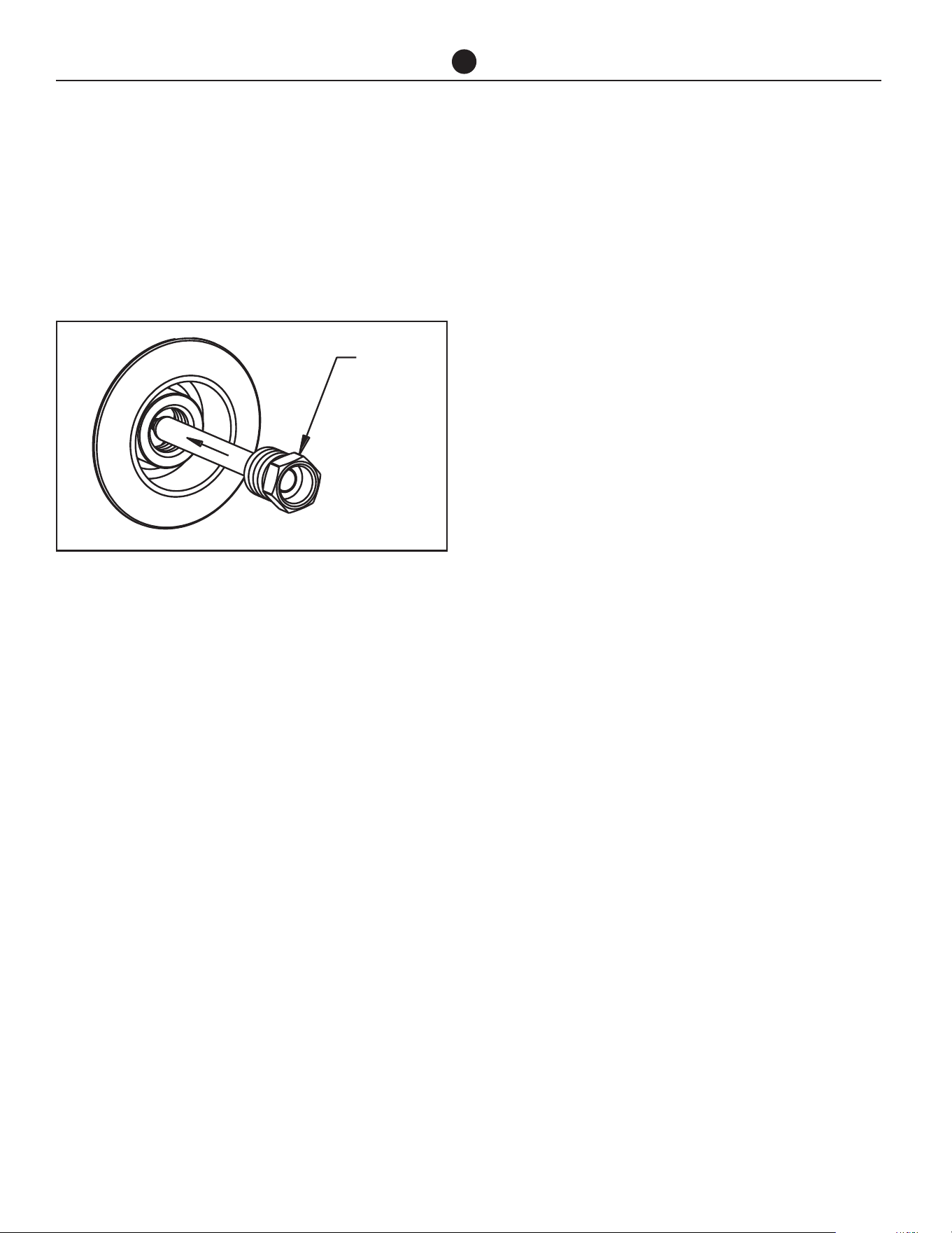
TANK SENSOR INSTALLATION
Connect one of the supplied temperature sensors to
the connection terminal on the heat pump marked
“Tank Sensor”.
• Run out the sensor to the nearest storage tank.
• Insert a Thermostat Well (not supplied) into the
tank.
• Insert the sensor all the way into the thermostat
well and secure it to the storage tank to prevent the
sensor dislodging from the well.
• Cable tie the sensor lead, curling up and tying off
any excess lead.
BUILDING FLOW TEMPERATURE
SENSOR INSTALLATION
• Connect the 2nd temperature sensor to the con-
nection terminal on the heat pump marked “Build-
ing Flow Sensor”.
• Run out the sensor to the building flow pipe.
• Fit a thermostat well (not supplied) in the pipe en-
suring the end of the sensor is in the flow of water.
To prevent the sensor dislodging from the well, se-
cure the sensor to the insulation using a cable tie.
Alternatively, clamp the sensor to the outside of the
pipe using a pipe clamp prior to the insulation be-
ing fitted.
NOTE: For multiple heat pump installation, the pre-
ferred method is to interconnect the heat pumps (up
to 4 maximum) via LAN cables, available as an acces-
sory (part number: 17534).
In this case, only one tank sensor and building flow
temperature sensor is required, which are connected
to the heat pump designated as the Primary.
Alternatively, each heat pump can operate indepen-
dently in which case each tank sensor and building
flow temperature sensor must be connected and fitted
as described above.
LOW AMBIENT BOOST
If auxiliary boosting is required for low ambient opera-
tion, the booster should be interlocked with the heat
pump to only operate under low ambient or fault condi-
tions.
CONNECTIONS - ELECTRICAL
THERMOSTAT
WELL
Commercial Air to Water Heat Pump Water Heater
35
CONNECTIONS - ELECTRICAL
AUXILIARY BOOST ELEMENT
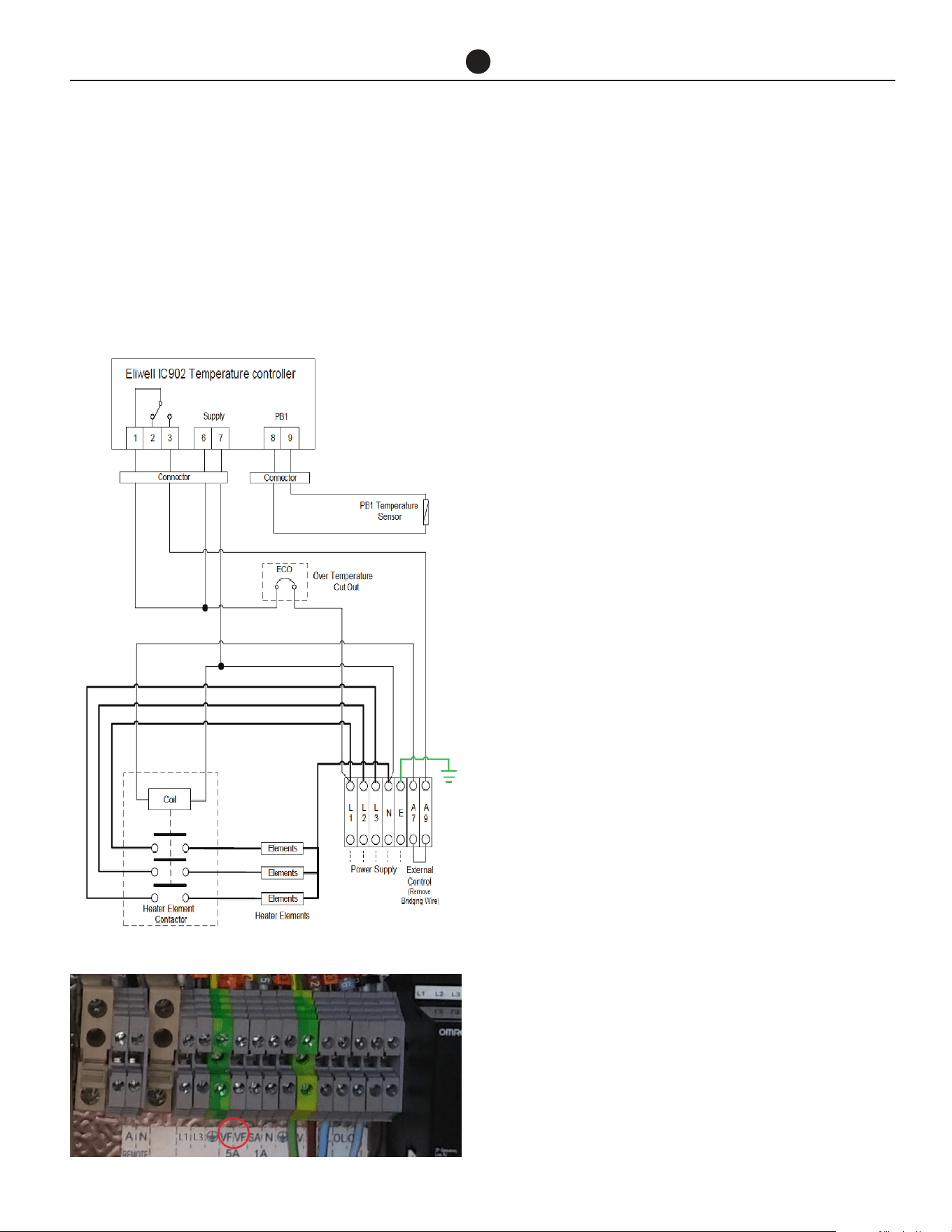
If a single auxiliary boost element is supplied by Rheem,
remove bridging wire at the terminals marked ‘A7 and
A9’ behind the element controller cover and connect
the terminal A7 and A9 to the voltage free terminal
marked ‘VF’ in the heat pump enclosure to control the
operation of the boost element.
Where multiple auxiliary boost elements are required,
and the number of auxiliary boost elements matches
the number of heat pumps, each element may be inter-
locked with an individual heat pump directly using the
method described above. In this case, the heat pumps
should operate independently and each have their own
tank and building flow temperature sensor connected.
Where the number of auxiliary boost does not match
the number of heat pumps or the heat pumps are con-
nected in a Primary/Secondary arrangement using LAN
cables (refer to next page), then the heat pumps must
be connected via LAN cables and control of the auxil-
iary boost elements will be via the Primary heat pump
using an intermediary relay arrangement. Refer to Ap-
plication Guide for more detail.
AUXILIARY BOOST HEATER (EX-
TERNAL TO STORAGE TANK)
Depending on the installation, an auxiliary heater and/
or boost pump may be supplied. Refer to Application
Guide for auxiliary boost options.
In the heat pump enclosure, terminals marked “SA”, “N”
and “GND” provide 24V to control the auxiliary heater
and/or auxiliary pump or multiple boost elements de-
pending on the system design. Maximum current is 1A.
Refer to Application Guide for further information to
connect auxiliary boost heater.
NOTE: Where multiple heat pumps are required, the
heat pumps must be connected in a Primary/Second-
ary arrangement using LAN cables (refer to page 53),
and control of the auxiliary boost heaters will be via
the Primary heat pump. Refer to Application Guide for
more details.
480V/60HZ
Electric Heating Unit - Wiring Diagram.
Picture of heat pump terminal strip.
Commercial Air to Water Heat Pump Water Heater
36
CONNECTIONS - ELECTRICAL
MULTIPLE HEAT PUMP
INSTALLATION
Up to four heat pumps can be interconnected by daisy
chaining the LAN cables for operation as shown below.
LAN cable is available as an accessory (part number:
17534).
Step 1:
Interconnect the heat pumps as shown above by using
the LAN cables. Determine the 1st heat pump as Pri-
mary. Route the cables neatly to prevent damage and
trip hazards. Do not route across access panels.
Note: Any of the two LAN connections will be accept-
able.
Note
1. Tank temperature sensor for the Primary heat pump
must be connected, otherwise the heat pumps will
not operate due to fault. There is no need to con-
nect tank temperature sensors for Secondary heat
pumps.
2. Building temperature sensor for the Primary heat
pump must be connected. There is no need to con-
nect building temperature sensors for Secondary
heat pumps.
3. Ignore the values for tank and building temperature
sensors on the display of Secondary heat pumps
as these are not connected.
BUILDING MANAGEMENT
SYSTEMS (BMS/BAS)
Each water heater can be connected to a BMS or BAS
system via interface cards (Modbus RS485 or BACnet
MS-TP or BACnet TCP/IP Ethernet), available as an ac-
cessory.
Based on site requirement, a suitable interface card
needs to be connected to the control panel as shown
in the diagram below.
• If the system is comprised of single or multiple
standalone heat pumps, each heat pump will have
its own BMS card.
Insert the BMS card into the connector for each heat
pump, taking care that the card is firmly placed as
shown in red circle.
• If the system is comprised of multiple heat pumps
for Primary/Secondary operation, only primary heat
pump will have a BMS card and the secondary heat
pumps will be connected via LAN cables.
Follow the instruction on previous page for Intercon-
necting Multiple Heat Pumps from step 1 to step 2.
Insert the BMS card into the connector for primary
heat pump, taking care that the card is firmly placed as
shown in red circle.
1st Heat
Pump /
Primary
2nd Heat
Pump
3rd Heat
Pump
4th Heat
Pump
Commercial Air to Water Heat Pump Water Heater
37
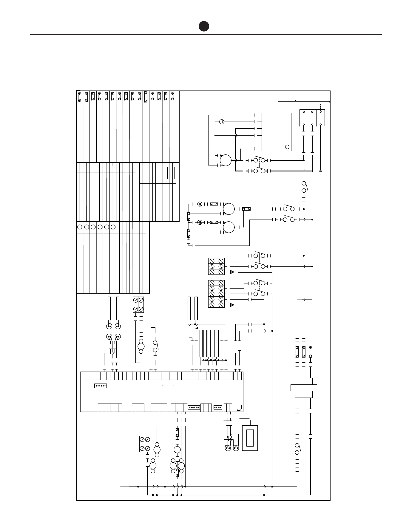
CONNECTIONS - ELECTRICAL
HPHD-60VN
22/09/2020
47229E
EARTH
-
-
(FIELD WIRING)
INCOMING MAINS
2
R3
TERMINAL CONNECTORJ7
PLD TERMINAL CONNECTOR
J4
J9
DIGITAL INPUT
BMS CONNECTION
POWER SUPPLY
LEGEND
J1
J6
J5
ANALOG OUTPUT
J8 uPC BUS
VALVE 1 CONTROL OUTPUT
J11
ANALOG INPUTJ3
RS485 / tLAN CONNECTOR
J10
PROBE SUPPLYJ2
J12
J13
J14
J15
J16
RELAY DIGITAL OUTPUT GROUP 1
DIGITAL INPUT
RELAY DIGITAL OUTPUT GROUP 1
RELAY DIGITAL OUTPUT GROUP 2
RELAY DIGITAL OUTPUT GROUP 3
J17
VALVE 2 CONTROL OUTPUT
J18
ANALOGUE INPUT
6 5
4 3
TERMINAL BLOCK - ACTIVE
A
TERMINAL BLOCK - NEUTRAL
N
TERMINAL BLOCK - SOLENOID VALVE
SV
TERMINAL BLOCK - ALARM ACTIVE
AL
TERMINAL BLOCK - VOLT FREE
VF
TERMINAL BLOCK - EARTH
E
TERMINAL BLOCK - FAN COMMON
C
C
RS
5uF
C
RS
5uF
R 40
S S
R
L1
-
TERMINAL BLOCK - SWITCH ACTIVE 24V AC
SA
C
RS
COMPRESSOR
80uF
L3
C1
L1
T1
L3
T3
RUN
SOFT STARTER
RUN
ACTIVE (T2)
START
COMMON (C)
WINDING (R)
CAPACITOR (RC)
WINDING (S)
COMPRESSOR
TRANSFORMER
COM
COM
208
240
24
12
1 2
CB 10A
1
3
COM
208V
240V
2
3
NOTE:
WIRED FOR 208 VOLTS.
FOR 240 VOLTS MOVE WIRE 2
TRANSFORMER IS FACTORY
FROM TERMINAL 208 TO 240
HPHD-60VN#-201
38
C
TERMINAL BLOCK - PUMP L1
L1
TERMINAL BLOCK - FAN RUN
R
TERMINAL BLOCK - Transformer 208V 60HZ
208
TERMINAL BLOCK - PUMP L3
L3
TERMINAL BLOCK - Transformer COMMON
TERMINAL BLOCK - FAN START
S
TERMINAL BLOCK - Transformer 240V 60HZ
240
COM
COMPRESSOR CONTACTOR
LEGEND
C1
CB CIRCUIT BREAKER
R1
R2
R3
REMOTE ON/OFF RELAY COIL
EVAP FAN RELAY COIL
AUX BOOST RELAY COIL
SV
DEFROST SOLENIOD VALVE
C1
COMPRESSOR CONTACTOR COIL
REMOTE ON/OFF RELAYR1
EVAP FAN RELAY
R2 AUX BOOST RELAY
R3
LOCAL AREA NETWORK SOCKETLAN
VOLT FREE NORMALLY OPEN (AUX BOOST)VF
TEMPERATURE SENSOR PLUG & SOCKETTS
R4
PUMP RELAY COIL
PUMP RELAYR4
LEGEND
DESCRIPTIONECN
REV
Drawn By:
Fax: (02) 9684 3698
Revesby NSW 2212
Phone: (02) 9684 3684
43 Marigold Street
J.Bates
Date:
Part No:
02
Rev:
G
+Vdc
B1
DI1
NO6
G0
GND
+5VR
B2
B3
B4
B5
B6
B7
GND
+Vdc
DI2
DI3
DI4
DI5
DI6
DI7
DIC1
NO5
NO4
C2
R-/T-
R+/T+
GND
BMS
(OPTIONAL)
J1
J2
J3
J6
J4
J7
J8
J10
J11
J13
9
10
11
12
13
14
15
16
17
18
19
7
29
HIGH PRESS T/D
LOW PRESS T/D
87 R4
87 R228
R1
DISPLAY
NO3
NO2
NO1
C1
Vout
R-/T-
R+/T+
GND
J9
J12
7
24
25
26
SV
87 R3
SV N
44
43
42
GND
Y1
Y2
Y3
Y4
B8
B9
B10
B11
B12
GND
DI8
DI9
DI10
DIC2
J5
J18
J16
J17
NC7
C3
NO7
NO10
NO9
NO8
C4
NO12
NO11
J14
J15
30
7
AL
7
A2C1
87 R1
A
N
31 32
N
OUTDOOR AMBIENT
O/DOOR COIL TEMP
SUCTION TEMP
HOT ENTERING TEMP
HOT LEAVING TEMP
CAREL UPC
8
6
4
5
3
R4
E
PUMP
VF SA N E
AUX BOOST
6 5
R2
4 3
VF
33 34 35 36 37 8
46
23
20
21
ALARM
24V AC
TS
BUILDING FLOW
TS
STORAGE TANK
1 2
CONTROL CB 2A
6 7
8
L1 L3
REMOTE ON-OFF
24V AC
LAN
LAN
DATE
30/10/20Add wire colour and numbers0406
01
BK WH
BK WH
GY
GNYE
BK2
BK1
BK1
BK2
BK2
BK1
RD
GY
RD
RD
GY RD
GY GY RD
RD
GY
GY GY
GY
RD
RD
RD
RD
RD
RD
BK
RD
WH
WH
RD
RD
A1
BK1 BK2
GY
GY
GY
GY
GY
RD
RD
1.0mm²
LEGEND WIRE SIZE OR COLOUR
10.0mm²
BLACK MULTI COREBK1,2,3
GREEN / YELLOW
GNYE
GRAY
GY
WHITE
WH
RED
RD
BLACK
BK
BK
WH
WH
BK
BK
BK
BK
WH
WH
WH
BK
WH BN WH BN BK
BK WH
WHBN
6.0mm²
BROWNBN
WHBK
WH WH
WHWH
WH
BU BU
BKBRBKBR
BLUEBU
BK
EVAPORATOR
FANS
4 5
40
31/05/21Removed discharge temp sensor0432
02
ACTIVE
NEUTRAL
7
8
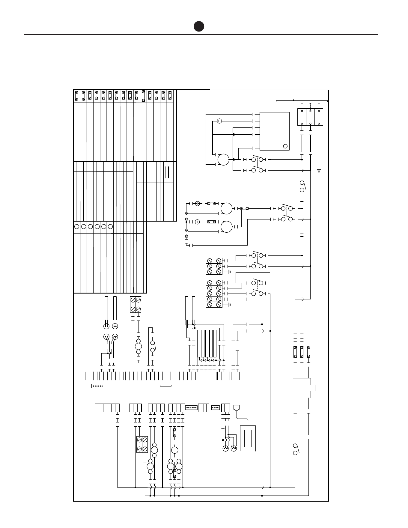
Commercial Air to Water Heat Pump Water Heater
38
CONNECTIONS - ELECTRICAL
HPHD-60HN
26/02/2021
47285E
EARTH
-
-
(FIELD WIRING)
INCOMING MAINS
2
R3
TERMINAL CONNECTORJ7
PLD TERMINAL CONNECTOR
J4
J9
DIGITAL INPUT
BMS CONNECTION
POWER SUPPLY
LEGEND
J1
J6
J5
ANALOG OUTPUT
J8 uPC BUS
VALVE 1 CONTROL OUTPUT
J11
ANALOG INPUTJ3
RS485 / tLAN CONNECTOR
J10
PROBE SUPPLYJ2
J12
J13
J14
J15
J16
RELAY DIGITAL OUTPUT GROUP 1
DIGITAL INPUT
RELAY DIGITAL OUTPUT GROUP 1
RELAY DIGITAL OUTPUT GROUP 2
RELAY DIGITAL OUTPUT GROUP 3
J17
VALVE 2 CONTROL OUTPUT
J18
ANALOGUE INPUT
6 5
4 3
TERMINAL BLOCK - ACTIVE
A
TERMINAL BLOCK - NEUTRAL
N
TERMINAL BLOCK - SOLENOID VALVE
SV
TERMINAL BLOCK - ALARM ACTIVE
AL
TERMINAL BLOCK - VOLT FREE
VF
TERMINAL BLOCK - EARTH
E
TERMINAL BLOCK - FAN COMMON
C
C
RS
5uF
C
RS
5uF
R 40
S S
R
L1
-
TERMINAL BLOCK - SWITCH ACTIVE 24V AC
SA
C
RS
COMPRESSOR
80uF
L3
C1
L1
T1
L3
T3
RUN
SOFT STARTER
RUN
ACTIVE (T2)
START
COMMON (C)
WINDING (R)
CAPACITOR (RC)
WINDING (S)
COMPRESSOR
TRANSFORMER
COM
COM
208
240
24
12
1 2
CB 10A
1
3
COM
208V
240V
2
3
NOTE:
WIRED FOR 208 VOLTS.
FOR 240 VOLTS MOVE WIRE 2
TRANSFORMER IS FACTORY
FROM TERMINAL 208 TO 240
HPHD-60HN#-201
38
C
TERMINAL BLOCK - PUMP L1
L1
TERMINAL BLOCK - FAN RUN
R
TERMINAL BLOCK - Transformer 208V 60HZ
208
TERMINAL BLOCK - PUMP L3
L3
TERMINAL BLOCK - Transformer COMMON
TERMINAL BLOCK - FAN START
S
TERMINAL BLOCK - Transformer 240V 60HZ
240
COM
COMPRESSOR CONTACTOR
LEGEND
C1
CB CIRCUIT BREAKER
R1
R2
R3
REMOTE ON/OFF RELAY COIL
EVAP FAN RELAY COIL
AUX BOOST RELAY COIL
SV
DEFROST SOLENIOD VALVE
C1
COMPRESSOR CONTACTOR COIL
REMOTE ON/OFF RELAYR1
EVAP FAN RELAY
R2 AUX BOOST RELAY
R3
LOCAL AREA NETWORK SOCKETLAN
VOLT FREE NORMALLY OPEN (AUX BOOST)VF
TEMPERATURE SENSOR PLUG & SOCKETTS
R4
PUMP RELAY COIL
PUMP RELAYR4
LEGEND
DESCRIPTIONECN
REV
Drawn By:
Fax: (02) 9684 3698
Revesby NSW 2212
Phone: (02) 9684 3684
43 Marigold Street
J.Bates
Date:
Part No:
01
Rev:
G
+Vdc
B1
DI1
NO6
G0
GND
+5VR
B2
B3
B4
B5
B6
B7
GND
+Vdc
DI2
DI3
DI4
DI5
DI6
DI7
DIC1
NO5
NO4
C2
R-/T-
R+/T+
GND
BMS
(OPTIONAL)
J1
J2
J3
J6
J4
J7
J8
J10
J11
J13
ACTIVE
NEUTRAL
9
10
11
12
13
14
15
16
17
18
19
7
7
29
HIGH PRESS T/D
LOW PRESS T/D
8
87 R4
87 R228
R1
DISPLAY
NO3
NO2
NO1
C1
Vout
R-/T-
R+/T+
GND
J9
J12
7
24
25
26
SV
87 R3
SV N
44
43
42
GND
Y1
Y2
Y3
Y4
B8
B9
B10
B11
B12
GND
DI8
DI9
DI10
DIC2
J5
J18
J16
J17
NC7
C3
NO7
NO10
NO9
NO8
C4
NO12
NO11
J14
J15
30
7
AL
7
A2C1
87 R1
A
N
31 32
N
OUTDOOR AMBIENT
O/DOOR COIL TEMP
SUCTION TEMP
HOT ENTERING TEMP
HOT LEAVING TEMP
CAREL UPC
8
6
4
5
3
R4
E
PUMP
VF SA N E
AUX BOOST
6 5
R2
4 3
VF
33 34 35 36 37 8
46
23
20
21
ALARM
24V AC
TS
BUILDING FLOW
TS
STORAGE TANK
1 2
CONTROL CB 2A
6 7
8
L1 L3
REMOTE ON-OFF
24V AC
LAN
LAN
DATE
BK WH
BK WH
GY
GNYE
BK2
BK1
BK1
BK2
BK2
BK1
RD
GY
RD
RD
GY RD
GY GY RD
RD
GY
GY GY
GY
RD
RD
RD
RD
RD
RD
BK
RD
WH
WH
RD
RD
A1
BK1 BK2
GY
GY
GY
GY
GY
RD
RD
1.0mm²
LEGEND WIRE SIZE OR COLOUR
10.0mm²
BLACK MULTI COREBK1,2,3
GREEN / YELLOW
GNYE
GRAY
GY
WHITE
WH
RED
RD
BLACK
BK
BK
WH
WH
BK
BK
BK
BK
WH
WH
WH
BK
WH BN WH BN BK
BK WH
WHBN
6.0mm²
BROWNBN
WHBK
WH WH
WHWH
WH
BU BU
BKBRBKBR
BLUEBU
BK
EVAPORATOR
FANS
4 5
40
31/05/21Removed discharge temp sensor0432
01
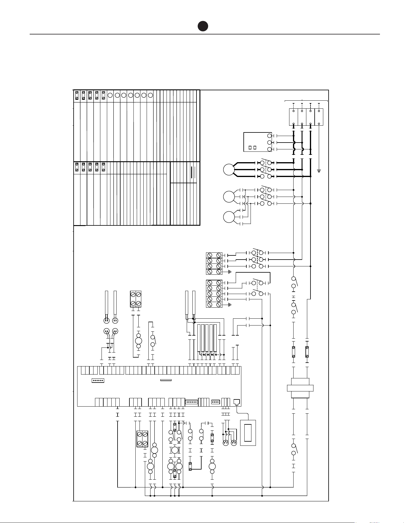
Commercial Air to Water Heat Pump Water Heater
39
HPHD-60HN
CONNECTIONS - ELECTRICAL
DESCRIPTIONECN
REV
Drawn By:
Fax: (02) 9684 3698
Revesby NSW 2212
Phone: (02) 9684 3684
43 Marigold Street
J.Bates
Date: 21/09/2020
Part No:
47224E
03
Rev:
EARTH
-
L1
-
(FIELD WIRING)
INCOMING MAINS
L2
-
L3
-
G
+Vdc
B1
DI1
NO6
G0
GND
+5VR
B2
B3
B4
B5
B6
B7
GND
+Vdc
DI2
DI3
DI4
DI5
DI6
DI7
DIC1
NO5
NO4
C2
R-/T-
R+/T+
GND
BMS
(OPTIONAL)
J1
J2
J3
J6
J4
J7
J8
J10
J11
J13
ACTIVE
NEUTRAL
9
10
11
12
13
14
15
16
17
18
19
7
7
29
HIGH PRESS T/D
LOW PRESS T/D
8
A2A1 C2
87 R228
R1
DISPLAY
39
NO3
NO2
NO1
C1
Vout
R-/T-
R+/T+
GND
J9
J12
7
24
25
26
SV
A2A1 C3
SV N
41
44
43
42
PHASE FAIL ROTATION RELAYPF
COMPRESSOR CONTACTOR
LEGEND
C1
CB CIRCUIT BREAKER
C2
R1
R2
C2
AUX BOOST RELAY COIL
PUMP CONTACTOR COIL
SV
DEFROST SOLENIOD VALVE
GND
Y1
Y2
Y3
Y4
B8
B9
B10
B11
B12
GND
DI8
DI9
DI10
DIC2
J5
J18
J16
J17
NC7
C3
NO7
NO10
NO9
NO8
C4
NO12
NO11
J14
J15
30
7
AL
7
C1
COMPRESSOR CONTACTOR COIL
EVAP FANS CONTACTOR
REMOTE ON/OFF RELAYR1
R2 AUX BOOST RELAY
R4
FAN OVERLOAD 1F O/L 1
F O/L 2 FAN OVERLOAD 2
TERMINAL BLOCK - ACTIVE
A
TERMINAL BLOCK - NEUTRAL
N
TERMINAL BLOCK - FAN O/L
OL
TERMINAL BLOCK - SOLENOID VALVE
SV
TERMINAL BLOCK - ALARM ACTIVE
AL
TERMINAL BLOCK - VOLT FREE
VF
TERMINAL BLOCK - EARTH
E
A2C1
R4
87 R4
3
5
46
F O/L 2
BK2
FAN OVERLOAD RELAY
EVAP FAN CONTACTOR COIL
R4
REMOTE ON/OFF RELAY COIL
FAN OVERLOAD RELAY COIL
C3
87 R1
A
N
31 32
C3
PUMP CONTACTOR
N
OUTDOOR AMBIENT
O/DOOR COIL TEMP
SUCTION TEMP
HOT ENTERING TEMP
HOT LEAVING TEMP
LOCAL AREA NETWORK SOCKETLAN
VOLT FREE NORMALLY OPEN (AUX BOOST)VF
TEMPERATURE SENSOR PLUG & SOCKETTS
CAREL UPC
8
27
45
L1
T1
L2
T2
L3
T3
L2
COMPRESSOR
C1
L1 L2 L3
PHASE FAIL
L3L1
PWR
RY
4
1 2
CONTROL CB 10A
11 14
PF
L1
T1
L3
T3
C2
E
PUMP
VF SA N E
AUX BOOST
6 5
R2
4 3
VF
45 34 35 36 37 8
L1
T1
L2
T2
L3
T3
EVAPORATOR FANS
C3
TERMINAL BLOCK - SWITCH ACTIVE
SA
46
OL
38
F O/L 1
OL
23
20
21
ALARM
24V AC
TS
BUILDING FLOW
TS
STORAGE TANK
HPHD-135#N#-483
1 2
CONTROL CB 2A
TRANSFORMER
COM
L3
24
12
L1
L3
5 6 7
8
L2 L3
REMOTE ON-OFF
24V AC
1
2
3
LAN
LAN
3
L1
DATE
TERMINAL CONNECTORJ7
PLD TERMINAL CONNECTOR
J4
J9
DIGITAL INPUT
BMS CONNECTION
POWER SUPPLY
LEGEND
J1
J6
J5
ANALOG OUTPUT
J8 uPC BUS
VALVE 1 CONTROL OUTPUT
J11
ANALOG INPUTJ3
RS485 / tLAN CONNECTOR
J10
PROBE SUPPLYJ2
J12
J13
J14
J15
J16
RELAY DIGITAL OUTPUT GROUP 1
DIGITAL INPUT
RELAY DIGITAL OUTPUT GROUP 1
RELAY DIGITAL OUTPUT GROUP 2
RELAY DIGITAL OUTPUT GROUP 3
J17
VALVE 2 CONTROL OUTPUT
J18
ANALOGUE INPUT
1.0mm²
LEGEND WIRE SIZE OR COLOUR
10.0mm²
TERMINAL BLOCK - PUMP L1
L1
TERMINAL BLOCK - PUMP L3
L3
30/10/20Add wire colour and numbers0406
01
BK
RD
WH
BK RD WHBK RD WHBK RD WH
BK WH
BK
WH
BK
BK RD WH BK1 BK2 BK3
BK WH
GY
BK1
40
BK1
BK2
GNYE
BK2
BK1
BK1
BK2
BK2
BK1
RD
GY
RD
RD
GY RD
GY GY RD
RD
GY
GY GY
GY
RD
RD
RD
RD
RD
RD
BK
RD
WH
WH
RD
RD
R4
RD
RD
A1
BK1 BK2
GY
GY
GY
GY
GY
GY
RD
RD
BLACK MULTI COREBK1,2,3
GREEN / YELLOW
GNYE
GRAY
GY
WHITE
WH
RED
RD
BLACK
BK
RD
BK
BK1 BK2 BK3BK1 BK2 BK3
31/05/21Removed discharge temp sensor0432
02
L2
T2
RD
BK2
33
L1
22/06/23480v water pump connections was split phase 0550
03
HPHD-135
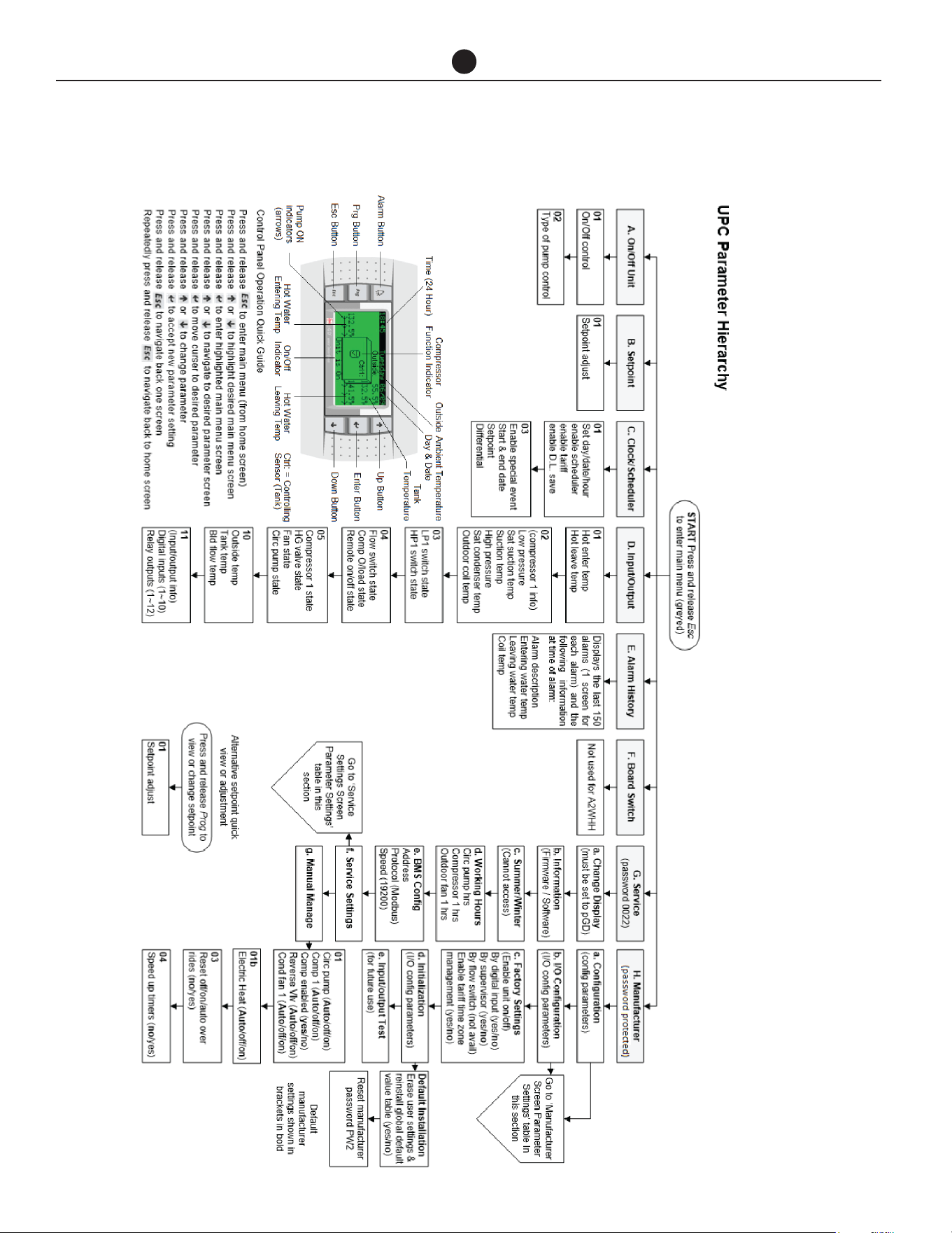
Commercial Air to Water Heat Pump Water Heater
40
CONTROLLER/DISPLAY
CONTROLLER AND DISPLAY INFORMATION

Commercial Air to Water Heat Pump Water Heater
41
CONTROLLER/DISPLAY
NOTE: If no keys are pressed for 60 seconds, screen
reverts to main display screen and any changes made
and not confirmed will be lost.
SETPOINT QUICK SETTING
Press ‘prg’ from the main display screen and the Set-
point page will appear. Cursor will be on the set tem-
perature. Pressing the up and down keys will adjust the
setting in 0.1 increments. Hold down for rapid change.
Press ’Enter’ to confirm change. Press ‘esc’ to return to
the main display screen. The factory setting is 141.8°F
(61°C). The setpoint can be adjusted up to 149°F (65°C)
depending on site suitability after consulting with
Rheem.
MENU ITEM
A. On/Off – Press ’enter’ to access change. Press ‘up’
or ‘down’ to turn unit on or off. Press ‘enter’ to con-
firm.
Press ‘down’ key to display type of circulating pump
control.
Default: AUTOMATIC ON TEMP
Press ‘esc’ to return to Menu Primary.
B. Setpoint - displays the tank maximum setpoint at
which the compressor will be deactivated. Cursor
will be on the set temperature. Pressing the ‘up’ and
‘down’ keys will adjust the setting in 0.1 increments.
Hold down for rapid change. Press ’enter’ to confirm
change. Press ‘esc’ to return to the Menu Primary.
C. Clock / Scheduler – time and date are set here. Other
adjustments include:
i. Enable Scheduler: No (controls heat pump operat-
ing time based on programmed time period)
ii. Enable Tariff: No (controls heat pump operating
time based on tariffs)
iii. Enable D.L. Save: No (shifts time based on sea-
sons)
i. Enabling Scheduler to ‘Yes’ will open a 2nd page
which will allow the user to program specified op-
erating times on a 7-day basis. E.g.:
Clock Schedule
Mon 00:00 to 00:00
Tue 00:00 to 00:00
Pressing the ‘down’ key will reveal a 2nd page in
the Clock Scheduler:
– Do you want to enable Special Event: No
(programs the temperature to be maintained
during a specified date range)
Enabling the Special Event to ‘Yes’ allows user to
program in the desired date range, setpoint and dif-
ferential to be maintained during the Special Event
period.
ii. Enabling Tariff to Yes will open the Tariff Time Band
pages which allows the user to program which
hours are off peak, shoulder and peak in 12 hour
blocks as Weekday AM, Weekday PM, Weekend
AM, Weekend PM.
Press ‘esc’ until page returns to the Menu Primary.

Commercial Air to Water Heat Pump Water Heater
42
CONTROLLER/DISPLAY
D. Input/output View – Displays the actual readings as
follows:
E. Alarm History – will display up to 150 alarm events
and then will overwrite oldest event. Alarms can be
cleared by pressing the ‘Alarm Bell’ key.
F. Service – password: 0022
a. Change display (do not use)
b. Information – software version information
c. Summer/Winter (not applicable to this product)
d. Working Hours:
i. Circ. Pump / reset counter
ii. Compressor 1 / reset counter
iii. Outdoor Fan 1 / reset counter
e. BMS configuration (will time out after 5 minutes if
no buttons pressed)
Address: 1 (if BMS Interface Card Modbus on RS485 is
used, change the address value based on the unique
address set by the customer’s network. For all other
BMS interface cards, ignore this value).
Protocol: CAREL/Modbus (choose Modbus only for
BMS Interface Card Modbus on RS485. For all other
BMS interface cards, choose CAREL).
Speed: 19200 (if BMS Interface Card Modbus on RS485
is used, change the speed value based on the custom-
er’s network. For all other BMS interface cards, use
19200 as speed).
f. Service Settings
a. Working Hour Set
b. Prove Adjustment
c. Thermoregulation (for multiple heat pump
installation, change the no. of compressor
and other settings from the table on the next
page.)
d. User DEV/Change PW1
For more information, please refer to the service man-
ual for heat pumps.
Hot Enter Temp: Potable water temperature entering and
leaving the condenser heat exchanger
Hot Leave Temp:
Cold enter Temp: Non-potable/chilled water temperature
entering and leaving the evaporator heat
exchanger
Cold Leave Temp:
Compressor 1 – Compressor temperature and pressure
readings
Low Press:
sat. suction:
Suction:
High Press:
sat. condenser:
out. coil Temp: Evaporator coil temperature
LP1 switch: OK Hi and Lo pressure switches closed or
open circuit
HP1 switch: OK
Flow switch: On/Off Flow switch in non-potable/chilled water
circuit activated
Comp O/Load: On/Off Compressor overload activated
Remote: On/Off Remote control of heat pump activated
Compressor 1: On/Off Compressor status
Rev. valve: On/Off Reversing valve status (NA)
Fan: On/Off Fan status
Circ. Pump: On/Off Primary pump/s status (NB: both non-
potable/chilled and potable water pumps
are activated by same relay)
Outside Temp: Ambient air sensor temperature
Tank Temp: Temperature at near bottom of tank
Building Flow Temp: Temperature being delivered to building
ow
Digital Inputs: Displays the number of inputs and
outputs
Relay Outputs:

Commercial Air to Water Heat Pump Water Heater
43
CONTROLLER/DISPLAY
Thermoregulation
Parameter Sub Parameter Primary Secondary
Thermoregulation 01
Setpoint 140°F (60.0°C) Screen N/A
Differential 10°F (3.0°C) Screen N/A
Dead band 33°F (0.5°C) Screen N/A
Thermoregulation 02
(De-ice temperature)
Initiate 25°F (-4°C) 25°F (-4°C)
Terminate 50°F (10.0°C) 50°F (10.0°C)
Thermoregulation 03
(De-ice timers)
Delay to start 5m 5m
Max duration 10m 10m
Min between 30m 30m
Coil de-water 30s 30s
Thermoregulation 04
(Pump settings)
Flow proof delay 3s Screen N/A
Pump min run 5m Screen N/A
Pump run on time 1m Screen N/A
Temp. test cycle Not avail Screen N/A
Flow switch tted No Screen N/A
Thermoregulation 04s Flow switch tted Screen N/A No
Thermoregulation 05
Blackout delay 10s Screen N/A
No of compressors
(number of heat pumps)
Set as required (default 1) Screen N/A
Compressor staging Simultaneous Screen N/A
Controlling sensor Tank Screen N/A
I/O Cong 05
Out air sensor Yes No
Sensor type Carel NTC Carel NTC
Thermoregulation 06
(Enable unit On/Off)
By digital input No Screen N/A
By supervisor No Screen N/A
By ow switch Not avail Screen N/A
Dig input 6 is for: Comp O/Load Screen N/A
I/O Cong 06b
Storage tank temp Yes No
Sensor type Carel NTC Carel NTC
Building ow temp Yes No
Sensor type Carel NTC Carel NTC
Thermoregulation 07
(HP/LP Safety)
LP trip set 0.4 Bar 0.4 Bar
HP trip set 27.5 Bar 27.5 Bar
Thermoregulation 08
(Anti-freeze safety for PHE
evaporator (leave))
Low limit set 32°F (0.0ºC) Screen N/A
Thermoregulation 09
Aux. Boost Fitted Yes Screen N/A
% compressor in alarm to
activate boost
50% Screen N/A
Boost act. Delay 5m Screen N/A
Thermoregulation 10
(Low outside air temp i.e
low ambient aux boost)
Cut over point 41°F (5.0ºC) Screen N/A
Differential 36°F (2.0ºC) Screen N/A
Comp stop in low outside
air temp:
Yes Screen N/A

Commercial Air to Water Heat Pump Water Heater
44
COMMISSIONING
TO FILL AND TURN ON THE
WATER HEATER
The power supply to the water heater and con-
troller must not be switched on until the water
heater is filled with water and a satisfactory
megger reading is obtained.
WARNING: This water heater contains elec-
tronic equipment and 500 V insulation tests
must only be conducted between actives and
earth and between neutral and earth. An active
to neutral test WILL damage the electronics.
COMMISSIONING PROCEDURE
– STANDALONE HEAT PUMP
CONFIGURATION
• Perform this procedure to commission a single
(standalone) heat pump.
• If the system is comprised of multiple stand-
alone heat pumps, perform this procedure for
each heat pump.
• Open all of the hot water taps in the building (don’t
forget the showers) and supply valves in the sys-
tem.
• Open the valves fully on the cold, return and hot
water branches to the storage tanks.
• Open the main cold water valve.
• Air will be forced out of the taps.
• Close each tap as water flows freely from it.
• Check the pipe work for leaks.
• Switch on the electrical supply at the isolating
switch to the water heater.
• Set time/tariff control if required.
• Reset alarms. Skip this step if there are no alarms.
If the water heater is full of cold water, the fan will acti-
vate and heating will commence unless the ambient air
temperature is below the ambient sensor setpoint, in
which case the auxiliary boost will operate, if installed.
It is important to wait for five minutes after the heat
pump has activated to ensure it continues to operate
and is functioning correctly.
NOTE: The water heater may not turn on immediately
when it is first switched on, if it is switched on within
20 minutes to 2 hours of it having been switched off at
the isolating switch, or the heat pump has just com-
pleted a heating cycle. The water heater will wait until
the conditions for start-up are favorable in order to
protect the compressor from damage. This may take
up to 20 minutes to 2 hours. The auxiliary booster (if
installed) will operate instead of the heat pump if the
ambient air temperature is less than the ambient sen-
sor setpoint.
Explain to a qualified technician the functions and op-
eration of the heat pump water heater. Upon comple-
tion of the installation and commissioning of the wa-
ter heating system, leave this guide with the qualified
technician.
COMMISSIONING PROCEDURE
– MULTIPLE HEAT PUMP (PRIMA-
RY/SECONDARY) CONFIGURA-
TION
Perform this procedure if the system is comprised of
multiple heat pumps to be configured for Primary/Sec-
ondary operation.
• Open all of the hot water taps in the building (don’t
forget the showers) and supply cocks and valves in
the system.
• Open the isolation valves fully on the cold, return
and hot water branches to the storage tanks.
• Open the main cold water valve on the cold water
line to the storage tanks.
Air will be forced out of the taps.
• Close each tap as water flows freely from it.
• Check the pipe work for leaks.
Before commencing the Primary/Secondary commis-
sioning procedure, ensure the ‘Multiple Heat Pump In-
stallation
- step 1 and step 2 have been completed as stated on
page 45.
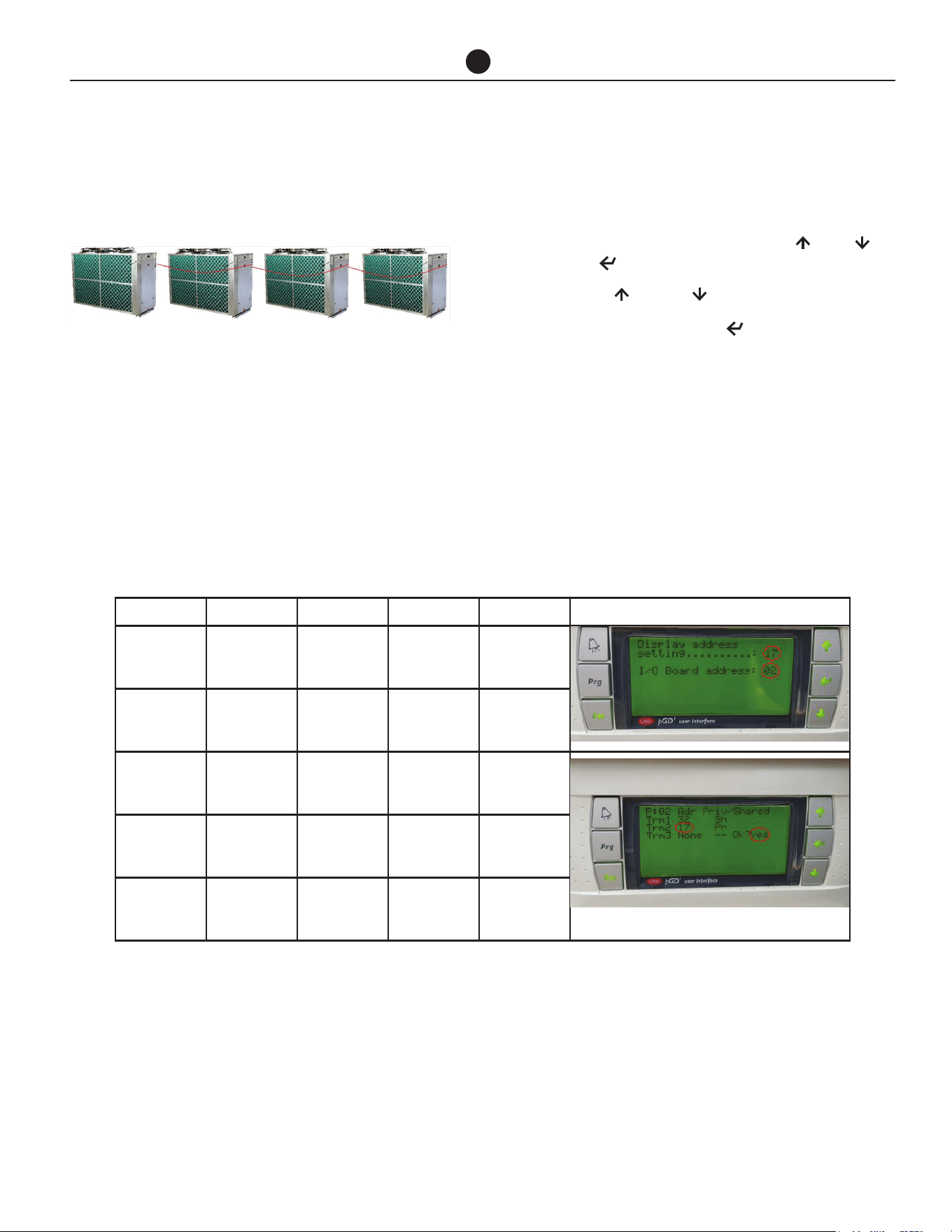
Commercial Air to Water Heat Pump Water Heater
45
COMMISSIONING
The commissioning procedure MUST be performed in
the order shown.
1. Ensure all heat pumps are turned OFF at the isolat-
ing switch.
2. Turn ON secondary 1 heat pump (2nd heat pump).
3. Configure heat pump address.
• While in the home screen on control panel,
simultaneously press and hold Up , Down
and Enter for 5 seconds to enter the setup
menu.
• Use Up or Down buttons to set values.
• Press and release Enter to move curser to
next line.
• Change the following values as shown in the
table at the bottom on this page.
• Press “Enter” to confirm settings. The screen
will change to the home screen and settings
will be saved.
Note that the secondary's pump will start and an alarm
may occur – ignore at this stage.
1st Heat
Pump /
Primary
2nd Heat
Pump
Secondary 1
3rd Heat
Pump
Secondary 2
4th Heat
Pump
Secondary 3
Menu Secondary 1 Secondary 2 Secondary 3 Primary Example Screen Image of Secondary 1
Display ad-
dress setting
17 18 19 16
I/O board
address
02 03 04 01
trm1 32 32 32 32
trm2 17 18 19 16
trm3 None –
Ok?
Yes Yes Yes Yes
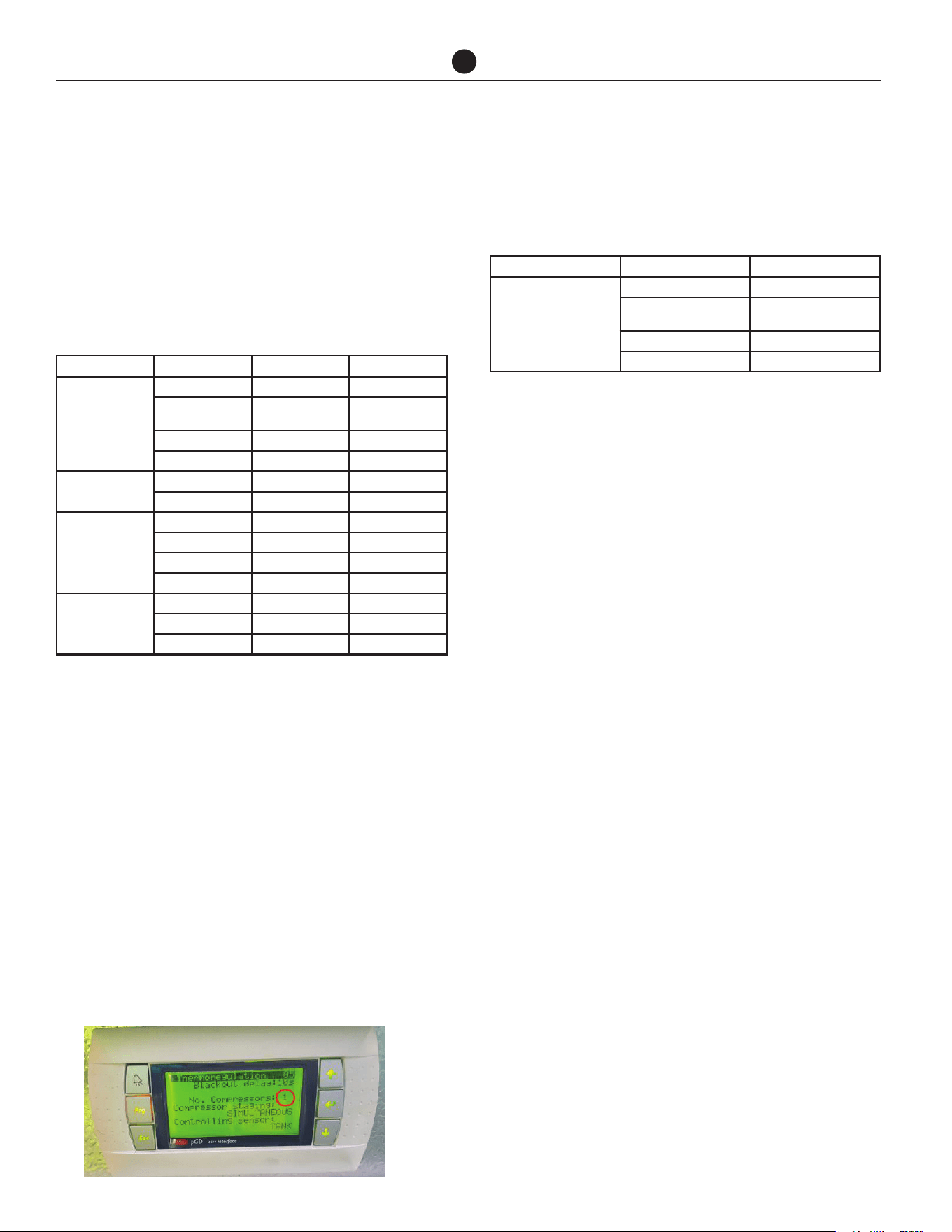
Commercial Air to Water Heat Pump Water Heater
46
COMMISSIONING
4. Change secondary heat pump 'Out air sensor',
'Storage tank temp' sensor and 'Building flow
temp' sensor parameters to 'No'.
• Go to the Service menu (Service>Service Set-
tings- password 0022>Thermoregulation). Re-
fer to page 50 to see the chart for navigating
Service menu and page 53 for Thermoregula-
tion section or see the table below.
5. Turn OFF the Secondary heat pump.
• If there is only 1 secondary proceed directly to
step 6.
• If there are 2 or 3 Secondary heat pumps repeat
step 3 to step 5 for Secondary 2 and Secondary
3 respectively using the values for respective
Secondary heat pumps.
6. Turn ON Primary heat pump and set the primary
address as stated in step 3.
7. After commissioning the Primary heat pump, go to
the Service menu (Service>Service Settings- pass-
word 0022>Thermoregulation>no. of compressor)
on the Primary heat pump and change the number
of compressors according to the number of heat
pumps interconnected together.
Refer to page 50 to see the chart for navigating Service
menu and page 53 for Thermoregulation section or see
the table below.
8. Turn on all the heat pumps.
9. Reset alarms on each heat pump. Skip this step if
there are no alarms.
10. Set time/tariff control on Primary heat pump if re-
quired. Refer to page 50 to see the chart for navi-
gating the control panel display.
If the water heaters are full of cold water, the fan will ac-
tivate on each water heater and heating will commence
unless the ambient air temperature is below the ambi-
ent sensor setpoint, in which case the auxiliary boost
will operate, if installed.
It is important to wait for five minutes after each heat
pump has activated to ensure it continues to operate
and is functioning correctly.
NOTE: The heat pump may not turn on immediately
when it is first switched on, if it is switched on within
20 minutes to 2 hours of it having been switched off at
the isolating switch, or the heat pump has just com-
pleted a heating cycle. The heat pump will wait until the
conditions for start-up are favorable in order to protect
the compressor from damage. This may take up to 20
minutes to 2 hours. The auxiliary booster (if installed)
will operate instead of the heat pump if the ambient air
temperature is less than the ambient sensor setpoint.
Explain to a responsible officer the functions and oper-
ation of the heat pumps. Upon completion of the instal-
lation and commissioning of the water heating system,
leave this guide with the responsible officer.
Parameter Sub Parameter Primary Secondary
Thermoregulation 05
Blackout delay 10s Screen N/A
No of compressors
Set as required
(default 1)
Screen N/A
Compressor staging Simultaneous Screen N/A
Controlling sensor Tank Screen N/A
I/O Cong 05
Out air sensor Yes No
Sensor type Carel NTC Carel NTC
Thermoregulation 06
(Enable unit On/Off)
By digital input No Screen N/A
By supervisor No Screen N/A
By ow switch Not avail Screen N/A
Dig input 6 is for: Comp O/Load Screen N/A
I/O Cong 06b
Storage tank temp Yes No
Sensor type Carel NTC Carel NTC
Building ow temp Yes No
Parameter Sub Parameter Primary
Thermoregulation 05
Blackout delay 10s
No of compressors (Number
of heat pumps)
Set as required (default 1)
Compressor staging Simultaneous
Controlling sensor Tank
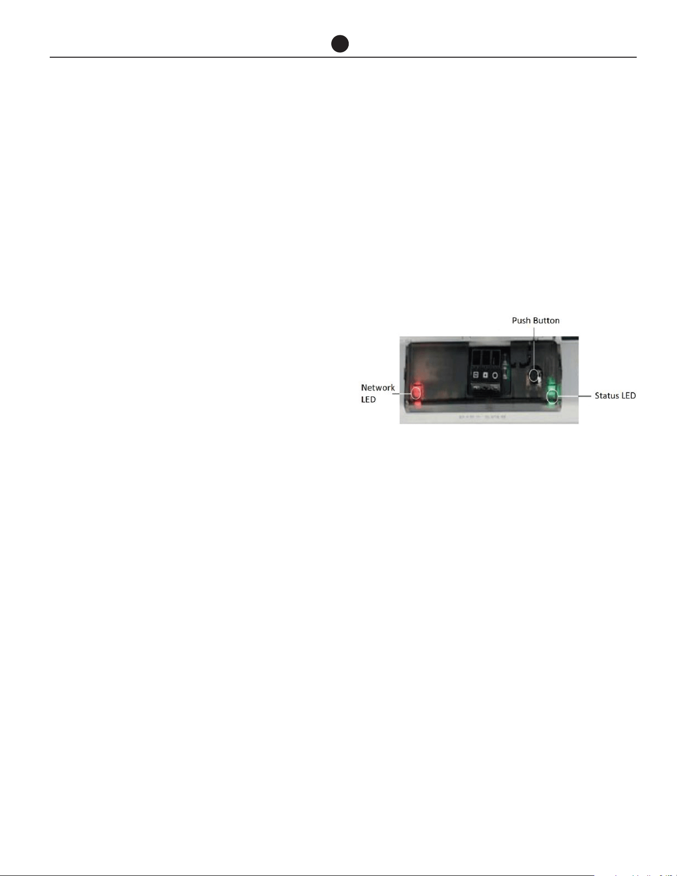
Commercial Air to Water Heat Pump Water Heater
47
COMMISSIONING
COMMISSIONING PROCEDURE-
BMS CONFIGURATION
Before commencing the commissioning procedure, en-
sure the ‘Building Management Systems (BMS/BAS)’
installation procedure has been completed as stated
on page 46.
• If the system is comprised of single or multiple
standalone heat pumps, perform this proce-
dure for each heat pump. Each heat pump will
have its own BMS card.
• If the system is comprised of multiple heat
pumps for primary/secondary operation, per-
form this procedure for only master heat pump.
Only primary heat pump will have a BMS card
and the secondary heat pumps will be connect-
ed via LAN cable.
Configure BMS settings from the display of the heat
pump.
After commissioning the primary heat pump, go to the
Service menu
(Service- password 0022>BMS config). Refer to page
50 to see the chart for navigating Service menu.
Configuration: BMS Interface Card Modbus on
RS485
1. Go to BMS configuration (will time out after 5 min-
utes if no buttons pressed)
Change the settings for BMS configuration from
the display menu as mentioned below.
Address: Change the address value based on the
unique address set by the customer’s network.
Protocol: Choose option ‘Modbus’
Speed: Change the speed value based on the cus-
tomer’s network.
2. Parameter table is provide for customers to follow
for further configuration to customer’s network on
page 59.
Configuration: BMS Interface card BACnet MS-
TP
1. Go to BMS configuration (will time out after 5 min-
utes if no buttons pressed)
Change the settings for BMS configuration from
the display menu as mentioned below.
Address: No change required (address is irrelevant
for this card).
Protocol: CAREL
Speed: 19200 (this value is set from factory to com-
municate between heat pump and BMS card)
2. Open the heat pump enclosure and check the
BMS card.
Functions of the button: When starting up the BACnet
MS-TP, this is used to select, for network communica-
tion, whether to use the factory parameters or the user
parameters
In normal operation, reboots BACnet MS-TP without
needing to disconnect the power supply
Status LED: indicates the status of communication
with the heat pump and the card. Once the starting se-
quence has been completed, the Status LED flashes to
indicate the quality of communication.
a. If Status LED flashes green, then communica-
tion with the BACnet MS-TP is OK.
b. If LED is red or green-red-green, then the com-
munication is not established. In that case,
check the BMS configuration.
Network LED: The Network LED (right) indicates the
status of communication with customer’s network.
Once the starting sequence has been completed, the
Network LED flashes to indicate the quality of commu-
nication with customer’s network.
The BACnet MS-TP card features a button (PUSHBUT-
TON) and two indicator lights (STATUS LED and NET-
WORK LED).
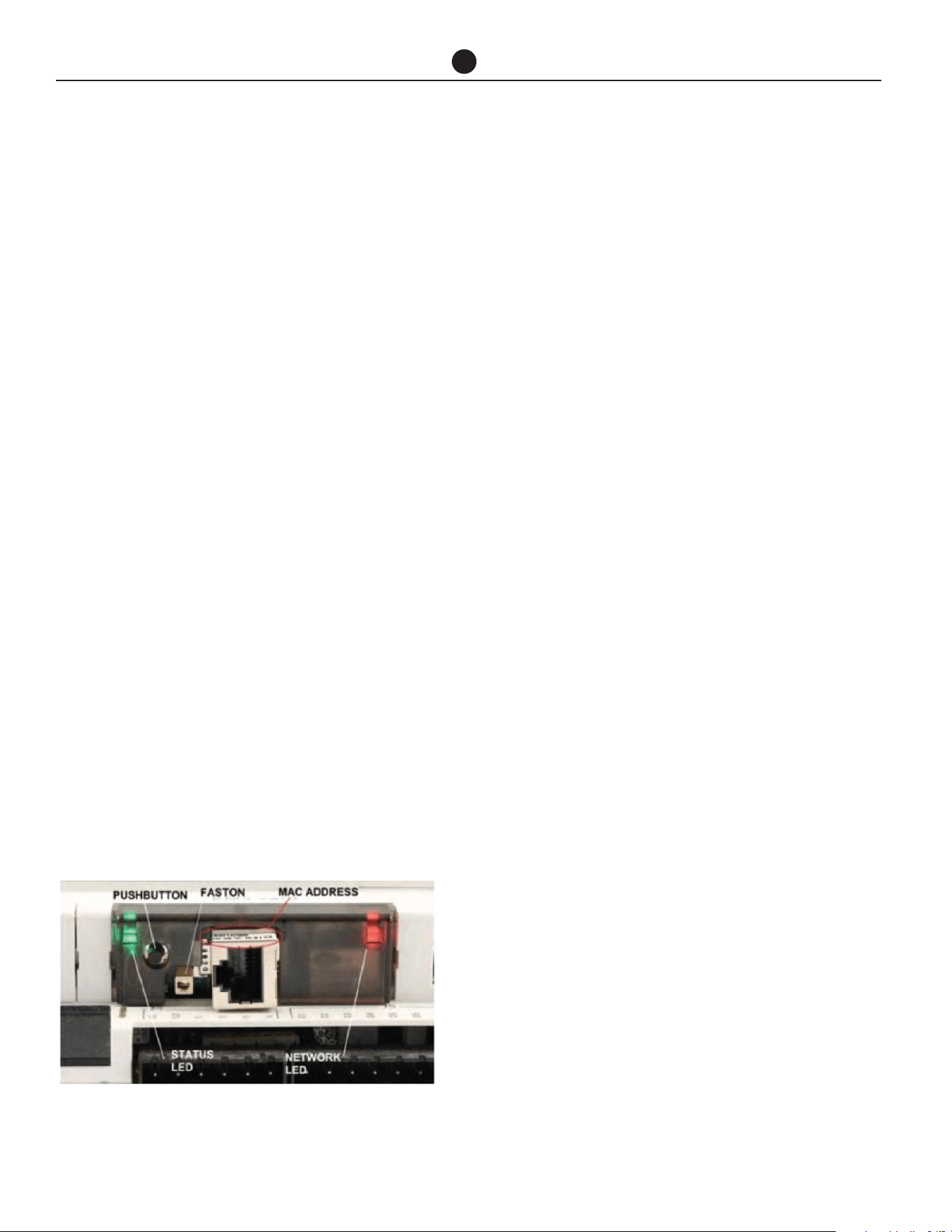
Commercial Air to Water Heat Pump Water Heater
48
a. If Network LED flashes green with occasional
red flashes then communication is OK.
b. If Network LED flashes green and red ON to-
gether (BACnet MS/TP meaning: continuous
Poll-For-Master): communication not estab-
lished (connection problems, or no network de-
vice found); this may depend on electrical con-
nection difficulties or communication settings
that are not compatible with the other network
devices connected.
3. For further configuration of BACnet MS-TP card,
please follow the “BACnet MS-TP Configuration
Guide”.
4. Parameter table is provided for customers to follow
for further configuration to customer’s network on
page 59.
Configuration: BMS Interface card BACnet TCP/
IP Ethernet
1. Go to BMS configuration (will time out after 5 min-
utes if no buttons pressed)
Change the settings for BMS configuration from
the display menu as mentioned below.
Address: No change required (address is irrelevant
for this card).
Protocol: CAREL
Speed: 19200 (this value is set from factory to com-
municate between heat pump and BMS card)
2. Open the heat pump enclosure and check the BMS
card.
Functions of the button: When starting up the TCP/IP
Ethernet card, this is used to select, for network com-
munication, whether to use the factory parameters or
the user parameters. In normal operation, reboots TCP/
IP Ethernet card without needing to disconnect the
power supply.
Status LED: indicates the status of communication
with the heat pump and the card. Once the starting se-
quence has been completed, the Status LED flashes to
indicate the quality of communication.
a. If Status LED flashes green or green steady,
then communication with the BACnet TCP/IP Eth-
ernet card is OK.
b. If LED is red or green-red-green, then the com-
munication is not established. In that case, check
the BMS configuration.
Network LED: Displays the status of the physical net-
work connection (Ethernet connection signals), regard-
less of whether the network parameters are correct;
usually this must be green and flash when data is trans-
mitted/received.
3. For further configuration of BACnet TCP/IP Ether-
net card, please follow the “BACnet TCP/IP Ether-
net Configuration Guide”.
4. Parameter table is provided for customers to follow
for further configuration to customer’s network on
page 59.
COMMISSIONING
The BACnet TCP/IP Ethernet card features a button
(PUSHBUTTON) and two indicator lights (STATUS LED
and NETWORK LED).

Commercial Air to Water Heat Pump Water Heater
49
Refer to the parameter tables below for BMS:
ANALOG VARIABLES
COMMISSIONING
BMS
Address
Description Default Category UOM Min Max
Read/
Write
Variable name
1 reading from input 1
Hot Entering water Sensor
0 Default --- -3276.8 3276.7 R Probe_Value_1
2 reading from input 2
Hot Leaving water Sensor
0 Default --- -3276.8 3276.7 R Probe_Value_2
3 reading from input 3 Out. coil sensor 0 Default --- -3276.8 3276.7 R Probe_Value_3
4 reading from input 4
Suction Temperature sensor
0 Default --- -3276.8 3276.7 R Probe_Value_4
5 reading from input 5 Out Air sensor 0 Default --- -3276.8 3276.7 R Probe_Value_5
6 reading from input 6
LP Pressure sensor tted
0 Default --- -3276.8 3276.7 R Probe_Value_6
7 reading from input 7
HP Pressure sensor tted
0 Default --- -3276.8 3276.7 R Probe_Value_7
8 reading from input 8 Cold Enter water 0 Default --- -3276.8 3276.7 R Probe_Value_8
9 reading from input 9 Cold Leave water 0 Default --- -3276.8 3276.7 R Probe_Value_9
10 reading from input 10
Hot Entering water Sensor
0 Default --- -3276.8 3276.7 R Probe_Value_10
11 reading from input 11
Hot Leaving water Sensor
0 Default --- -3276.8 3276.7 R Probe_Value_11
12 reading from input 12 Out. coil sensor 0 Default --- -3276.8 3276.7 R Probe_Value_12
13 Virtual Analoge Output 1 0 Default --- 0 3276.7 R VAOut_1
14 Virtual Analoge Output 2 0 Default --- 0 3276.7 R VAOut_2
15 Virtual Analoge Output 3 0 Default --- 0 3276.7 R VAOut_3
16 Virtual Analoge Output 4 0 Default --- 0 3276.7 R VAOut_4
17 Virtual Analoge Output 5 0 Default --- 0 3276.7 R VAOut_5
18 Virtual Analoge Output 6 0 Default --- 0 3276.7 R VAOut_6
19 Superheat valve Comp 1 0 Default --- -72.0 324.0 R Superheat_C1
20 Superheat valve Comp 2 0 Default --- -72.0 324.0 R Superheat_C2
21 Superheat valve Comp 3 0 Default --- -72.0 324.0 R Superheat_C3
22 Superheat valve Comp 4 0 Default --- -72.0 324.0 R Superheat_C4
23 Control Temperature 0 Default °F -146.2 211.82 R Ctrl_temp
24 Outside Air Temperature 0 Default BAR -146.2 211.82 R OAT
25 Entering water temperature 0 Default °F -146.2 211.82 R EW_temp
26 Leaving water temperature 0 Default °F -146.2 211.82 R LW_temp
27 Condenser temperature
(either from NTC or P-T)
0 Default --- -99.9 211.82 R Cond_temp
28 Current entering water Setpoint 22.0 Default °F 32 113 R Active_Setpoint
29 Active Proportional Band for compressor 1.5 Default °F 32 50 R Active_Pro_band
30 Water Setpoint 22.0 Default °F 41 113 R/W Setpoint
31 Dead band 1.0 Default °F 32 50 R/W D_Band
32 Proportional Band for compressor 1.5 Default °F 32 77 R/W Pro_band
33 Entering water temperature 2 0 Default °F -146.2 211.82 R EW_temp2
34 Leaving water temperature 2 0 Default °F -146.2 211.82 R LW_temp2
35 Storage tank water temperature 0 Default °F -146.2 211.82 R Tank_temp
36 Building Supply water temperature (Flow) 0 Default °F -146.2 211.82 R Bld_Supply_temp

Commercial Air to Water Heat Pump Water Heater
50
COMMISSIONING
BMS
Address
Description Default Category UOM Min Max
Read/
Write
Variable name
21 type of tariff - timeband 0 week end 0 Default --- 0 2 R/W trfw_0
22 type of tariff - timeband 1 week end 0 Default --- 0 2 R/W trfw_1
23 type of tariff - timeband 2 week end 0 Default --- 0 2 R/W trfw_2
24 type of tariff - timeband 3 week end 0 Default --- 0 2 R/W trfw_3
25 type of tariff - timeband 4 week end 0 Default --- 0 2 R/W trfw_4
26 type of tariff - timeband 5 week end 0 Default --- 0 2 R/W trfw_5
27 type of tariff - timeband 6 week end 0 Default --- 0 2 R/W trfw_6
28 type of tariff - timeband 7 week end 0 Default --- 0 2 R/W trfw_7
29 type of tariff - timeband 8 week end 0 Default --- 0 2 R/W trfw_8
30 type of tariff - timeband 9 0 Default --- 0 2 R/W trfw_9
31 type of tariff - timeband 10 week end 0 Default --- 0 2 R/W trfw_10
32 type of tariff - timeband 11 week end 0 Default --- 0 2 R/W trfw_11
33 type of tariff - timeband 12 week end 0 Default --- 0 2 R/W trfw_12
34 type of tariff - timeband 13 week end 0 Default --- 0 2 R/W trfw_13
35 type of tariff - timeband 14 week end 0 Default --- 0 2 R/W trfw_14
36 type of tariff - timeband 15 week end 0 Default --- 0 2 R/W trfw_15
37 type of tariff - timeband 16 week end 0 Default --- 0 2 R/W trfw_16
38 type of tariff - timeband 17 week end 0 Default --- 0 2 R/W trfw_17
39 type of tariff - timeband 18 week end 0 Default --- 0 2 R/W trfw_18
40 type of tariff - timeband 19 week end 0 Default --- 0 2 R/W trfw_19
41 type of tariff - timeband 20 week end 0 Default --- 0 2 R/W trfw_20
42 type of tariff - timeband 21 week end 0 Default --- 0 2 R/W trfw_21
43 type of tariff - timeband 22 week end 0 Default --- 0 2 R/W trfw_22
44 type of tariff - timeband 23 week end 0 Default --- 0 2 R/W trfw_23
49 State of unit. 0 Default --- 0 13 R Unit_Status
70 Compressor 1 Hour run counter (low) 0 Default --- 0 999 R Comp_T_Hours_L_1
71 Compressor 1 Hour run counter (high) 0 Default --- 0 999 R Comp_T_Hours_H_1
72 Compressor 2 Hour run counter (low) 0 Default --- 0 999 R Comp_T_Hours_L_2
73 Compressor 2 Hour run counter (high) 0 Default --- 0 999 R Comp_T_Hours_H_2
74 Compressor 3 Hour run counter (low) 0 Default --- 0 999 R Comp_T_Hours_L_3
75 Compressor 3 Hour run counter (high) 0 Default --- 0 999 R Comp_T_Hours_H_3
76 Compressor 4 Hour run counter (low) 0 Default --- 0 999 R Comp_T_Hours_L_4
77 Compressor 4 Hour run counter (high) 0 Default --- 0 999 R Comp_T_Hours_H_4
78 Pump Hour run counter (low) 0 Default --- 0 999 R Pump_T_Hours_L
79 Pump Hour run counter (high) 0 Default --- 0 999 R Pump_T_Hours_H
86 Outdoor Fan 1 Hour run counter (low) 0 Default --- 0 999 R OutFan_T_Hours_L_1
87 Outdoor fan 1 Hour run counter (high) 0 Default --- 0 999 R OutFan_T_Hours_H_1
88 Outdoor Fan 2 Hour run counter (low) 0 Default --- 0 999 R OutFan_T_Hours_L_2
89 Outdoor fan 2 Hour run counter (high) 0 Default --- 0 999 R OutFan_T_Hours_H_2
90 Outdoor Fan 3 Hour run counter (low) 0 Default --- 0 999 R OutFan_T_Hours_L_3
91 Outdoor fan 3 Hour run counter (high) 0 Default --- 0 999 R OutFan_T_Hours_H_3
92 Outdoor Fan 4 Hour run counter (low) 0 Default --- 0 999 R OutFan_T_Hours_L_4
93 Outdoor fan 4 Hour run counter (high) 0 Default --- 0 999 R OutFan_T_Hours_H_4
INTEGER VARIABLES

Commercial Air to Water Heat Pump Water Heater
51
COMMISSIONING
INTEGER VARIABLES
BMS
Address
Description Default Category UOM Min Max
Read/
Write
Variable name
100 15018 Default --- 0 32767 R BMS_Sw_Ver
101 15018 Default --- 0 32767 R BMS_Sw_Date
102 0 Default --- 0 9999 R Manuf_Password
103 Current year 0
Clock /
TimeDate
--- 0 99 R CURRENT_YEAR
104 Current month 1
Clock /
TimeDate
--- 1 12 R CURRENT_MONTH
105 Current day 1
Clock /
TimeDate
--- 1 31 R CURRENT_DAY
106 Current hour 0
Clock /
TimeDate
h 0 23 R CURRENT_HOUR
107 Current minute 0
Clock /
TimeDate
--- 0 59 R CURRENT_MINUTE

Commercial Air to Water Heat Pump Water Heater
52
COMMISSIONING
DIGITAL VARIABLES
BMS
Address
Description Default Category UOM Min Max
Read/
Write
Variable name
1 Digital Input 1 0 Default --- 0 1 R Din_1
2 Digital Input 2 0 Default --- 0 1 R Din_2
3 Digital Input 3 0 Default --- 0 1 R Din_3
4 Digital Input 4 0 Default --- 0 1 R Din_4
5 Digital Input 5 0 Default --- 0 1 R Din_5
6 Digital Input 6 0 Default --- 0 1 R Din_6
7 Digital Input 7 0 Default --- 0 1 R Din_7
8 Digital Input 8 0 Default --- 0 1 R Din_8
9 Digital Input 9 0 Default --- 0 1 R Din_9
10 Digital Input 10 0 Default --- 0 1 R Din_10
11 Digital Input 11 0 Default --- 0 1 R Din_11
12 Digital Input 12 0 Default --- 0 1 R Din_12
13 Digital Input 13 0 Default --- 0 1 R Din_13
14 Digital Input 14 0 Default --- 0 1 R Din_14
15 Digital Input 15 0 Default --- 0 1 R Din_15
16 Digital Input 16 0 Default --- 0 1 R Din_16
17 Digital Input 17 0 Default --- 0 1 R Din_17
18 Digital Input 18 0 Default --- 0 1 R Din_18
19 Virtual Digital Output 1 0 Default --- 0 1 R VDOut_1
20 Virtual Digital Output 2 0 Default --- 0 1 R VDOut_2
21 Virtual Digital Output 3 0 Default --- 0 1 R VDOut_3
22 Virtual Digital Output 4 0 Default --- 0 1 R VDOut_4
23 Virtual Digital Output 5 0 Default --- 0 1 R VDOut_5
24 Virtual Digital Output 6 0 Default --- 0 1 R VDOut_6
25 Virtual Digital Output 7 0 Default --- 0 1 R VDOut_7
26 Virtual Digital Output 8 0 Default --- 0 1 R VDOut_8
27 Virtual Digital Output 9 0 Default --- 0 1 R VDOut_9
28 Virtual Digital Output 10 0 Default --- 0 1 R VDOut_10
29 Virtual Digital Output 11 0 Default --- 0 1 R VDOut_11
30 Virtual Digital Output 12 0 Default --- 0 1 R VDOut_12
31 Virtual Digital Output 13 0 Default --- 0 1 R VDOut_13
32 Select if din 6 is Compressor Overload
or DRED
0 Default --- 0 1 R/W Sel_dred_ol
35 remote / maintenance enable of
compressor 1
1 Default --- 0 1 R/W Comp1_En
36 remote / maintenance enable of
compressor 2
1 Default --- 0 1 R/W Comp2_En
37 remote / maintenance enable of
compressor 3
1 Default --- 0 1 R/W Comp3_En
38 remote / maintenance enable of
compressor 4
1 Default --- 0 1 R/W Comp4_En
41 Actual status of compressor 1 0 Default --- 0 1 R Device_Status_Comp_1
42 Actual status of compressor 2 0 Default --- 0 1 R Device_Status_Comp_2
43 Actual status of compressor 3 0 Default --- 0 1 R Device_Status_Comp_3

Commercial Air to Water Heat Pump Water Heater
53
COMMISSIONING
BMS
Address
Description Default Category UOM Min Max
Read/
Write
Variable name
44 Actual status of compressor 4 0 Default --- 0 1 R Device_Status_Comp_4
45 Actual status of reverse valve 0 Default --- 0 1 R Device_Status_rev_vlv1
46 Actual status of reverse valve 2 0 Default --- 0 1 R Device_Status_rev_vlv2
47 Actual status of reverse valve 3 0 Default --- 0 1 R Device_Status_rev_vlv3
48 Actual status of reverse valve 0 Default --- 0 1 R Device_Status_rev_vlv4
49 On-Off unit state (0: Off; 1: On) 0 Default --- 0 1 R Sys_On
50 Supervisor (BMS) On-Off. Show the state
OFF by BMS in main mask (0: Off; 1: On)
0 Default --- 0 1 RW Superv_OnOff
51 Alarm reset from supervisory 1 Default --- 0 1 R/W RST_Alarms
52 Enable tariff time zone management 0 Default --- 0 1 R/W Trf_en
120 Alarm relay 0 Default --- 0 1 R Alarm
121 Alarm from probe on input 1 0 Alarms --- 0 1 R Al_probe_1
122 Alarm from probe on input 2 0 Alarms --- 0 1 R Al_probe_2
123 Alarm from probe on input 3 0 Alarms --- 0 1 R Al_probe_3
124 Alarm from probe on input 4 0 Alarms --- 0 1 R Al_probe_4
125 Alarm from probe on input 5 0 Alarms --- 0 1 R Al_probe_5
126 Alarm from probe on input 6 0 Alarms --- 0 1 R Al_probe_6
127 Alarm from probe on input 7 0 Alarms --- 0 1 R Al_probe_7
128 Alarm from probe on input 8 0 Alarms --- 0 1 R Al_probe_8
129 Alarm from probe on input 9 0 Alarms --- 0 1 R Al_probe_9
130 Alarm from probe on input 10 0 Alarms --- 0 1 R Al_probe_10
131 Alarm from probe on input 11 0 Alarms --- 0 1 R Al_probe_11
132 Alarm from probe on input 12 0 Alarms --- 0 1 R Al_probe_12
133 Alarm_comp1 0 Default --- 0 1 R Device_Alarm_comp1
134 Alarm_comp2 0 Default --- 0 1 R Device_Alarm_comp2
135 Alarm_comp3 0 Default --- 0 1 R Device_Alarm_comp3
136 Alarm_comp4 0 Default --- 0 1 R Device_Alarm_comp4
137 Compressor Overload 1 0 Default --- 0 1 R Comp_OL1
138 Compressor Overload 2 0 Default --- 0 1 R Comp_OL2
139 Compressor Overload 3 0 Default --- 0 1 R Comp_OL3
140 Compressor Overload 4 0 Default --- 0 1 R Comp_OL4
DIGITAL VARIABLES

Commercial Air to Water Heat Pump Water Heater
54
COMMISSIONING
DRAINING THE WATER HEATER
To Turn Off The Water Heater
If it is necessary to turn off the water heater on com-
pletion of the installation, such as on a building site or
where the premises are vacant, then:
• Switch off the electrical supply at the isolating
switch to the water heater.
• Close the cold water isolation valve at the inlet
to the system.
To drain the water heater:
• Turn off the water heater (refer to “To Turn Off
The Water Heater” on page 56.
• Close all hot water taps.
• Operate the relief valve release lever on one of
the storage tanks - do not let the lever snap
back or you will damage the valve seat.
• Operating the lever will release the pressure in
the water heater.
• Close the isolation valves at the inlet and outlet
of the water heater and place a bucket under
the cold water inlet.
• Undo the unions at the inlet and outlet of the
water heater. The heat pump heat exchanger
holds 1.3 to 2.6 gallons of water (model depen-
dent) and will drain into the bucket.
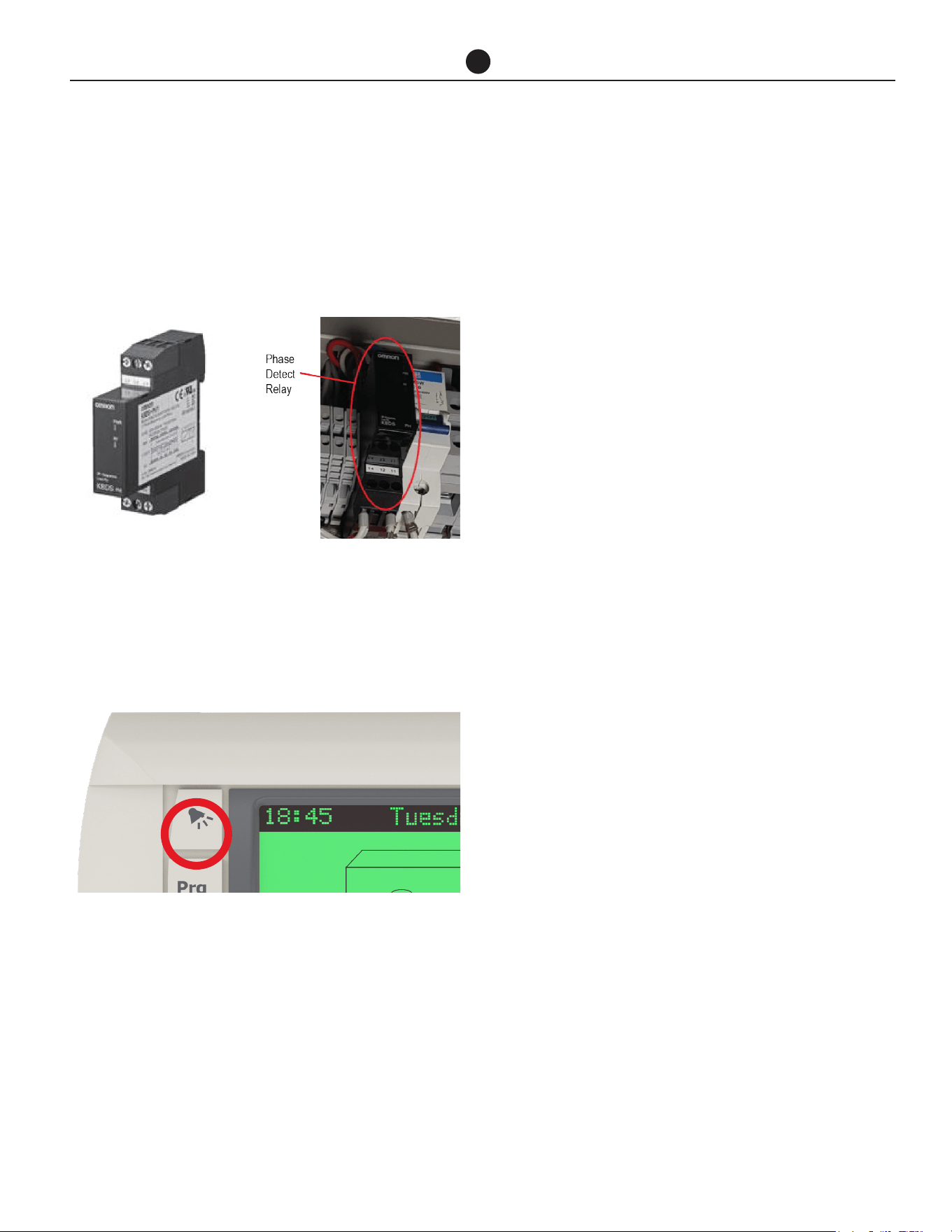
Commercial Air to Water Heat Pump Water Heater
55
TROUBLE SHOOTING
Heat Pump Won’t Start
A delay of up to 20 minutes to 2 hours can be experi-
enced before heat pump starts operating
Incorrect Phase Rotation
The phase detect relay will open circuit if the heat
pump has been wired with incorrect phase rotation or
if a phase has failed. Both green and yellow LEDs on
the relay will be illuminated if phase rotation is correct.
Alarm light on heat pump controller
If the alarm light is flashing RED, check the alarm by
pressing the alarm button. Phone your nearest Rheem
Service Department to inform about the alarm.
Low Ambient Temperature
If the ambient air temperature is below setpoint, the
heat pump may not start. Check the control panel of
the heat pump. Check outside ambient temperature
that shows on the display.
Heat pump starts then turns off soon after
This could be caused by:
a. Insufficient water flow rate through heat ex-
changer. Check pipe sizing per chart, check
obstructions, check lines and pump are bled,
check pump is operating, check temperature
rise across inlet and outlet.
NOTE: Tanks and heat pumps are to be manifolded
in Equa-Flow. It is important that the branches to
each storage tank ONLY contain a gate or ball valve
and union. Fitting of loose jumper valves, non-return
valves or pressure limiting valves in the branches or
primary flow and return lines between the heat pump
and tanks WILL affect performance of the heat pump.
b. Refrigerant charge too high? Refer to Alarm.
c. Refrigerant charge too low? Refer to Alarm.
Turn heat pump off then on again at isolating switch to
reset system.
Heat pump compressor excessively noisy
Check for correct phase rotation.

Commercial Air to Water Heat Pump Water Heater
56
AUTOMATIC DEFROST
The Commercial Heat Pump installation can be con-
figured in a number of ways depending on the require-
ments of the individual installation.
Ice may begin to form on the evaporator when the air
temperature falls below 45°F (7°C), and this will reduce
the heat pump efficiency. The water heating system
can be designed to operate in one of two scenarios in
low ambient temperature conditions.
When auxiliary heating mode is OFF, the heat pump will
use hot gas bypass to melt any ice that may form on
the evaporator coil when operating at air temperatures
below 41°F (5°C) and there will be no auxiliary boost.
When auxiliary heating mode is ON, the heat pump will
use hot gas bypass to melt any ice that may form on
the evaporator coil when operating at air temperatures
below 41°F (5°C) and auxiliary gas or electric water
heater will be activated. A pump circulates water from
the storage tanks through the auxiliary water heater un-
til the set temperature is reached.
The auxiliary heater should be set to 140°F (60°C).
For most applications, automatic defrost should be
satisfactory to meet the water heating demands.
The water heater can control an auxiliary heating source
if the ambient temperature falls below 41°F (5°C) or if
50% or more of the water heaters are in fault mode.

Commercial Air to Water Heat Pump Water Heater
57
CERTIFICATE OF LIMIT WARRANTY
COMMERCIAL AIR TO WATER HEAT PUMP WATER HEATER
For the Rheem, Ruud, Richmond, or Raypak Models listed
in this Manual.
GENERAL
This Limited Warranty is only available to the original
owner of this water heater. It is not transferable.
Rheem Manufacturing Company (Rheem®) warrants
this Rheem/Ruud/Richmond/Raypak water heater, and
its component parts, to be free from defects in materials
and workmanship, under normal use and service, for the
Applicable Warranty Period. At its option, Rheem will
repair or replace the defective water heater, or defective
component part(s), in accordance with the terms of this
Limited Warranty, if it fails in normal use and service
during the Applicable Warranty Period. The replace-
ment water heater must be manufactured by Rheem.
The replacement component part(s) must be Rheem
authorized component part(s). The replacement unit
will be warranted only for the unexpired portion of the
original unit’s Applicable Warranty Period.
EFFECTIVE DATE
The Effective Date of warranty coverage (or the begin-
ning of the Applicable Warranty Periods) is the date of
installation of the water heater, if properly documented.
Otherwise, it is the date of manufacture of the water
heater plus ninety (90) days.
APPLICABLE WARRANTY PERIODS
The Applicable Warranty Periods are one (1) year from
the Effective Date for the tank and the component
parts.
WARRANTY EXCLUSIONS
This Limited Warranty will not cover:
a) Service trips to your facility to teach you how to in-
stall, use, or maintain this water heater or to bring the
water heater installation into compliance with local
building codes and regulations.
b) Damages, malfunctions or failures resulting from fail-
ure to install the water heater in accordance with ap-
plicable building codes/ordinances or good plumb-
ing and electrical trade practices.
c) Damages, malfunctions, or failures resulting from im-
proper installation or failure to operate and maintain
the water heater in accordance with the manufac-
turer’s instructions provided.
d) Performance problems caused by improper sizing
of the water heater or (pertaining to electric models)
electric service voltage, wiring, or fusing.
e) Damages, malfunctions, or failures caused by abuse,
accident, fire, flood, freeze, lightning, acts of God,
and the like.
f) Coil failures (leaks) caused by operating the water
heater in a corrosive or contaminated atmosphere.
g) Damages, malfunctions, or failures caused by oper-
ating the water pump without any supply of water.
h) Damages, malfunctions, or failures caused by oper-
ating the unit at water temperatures exceeding the
maximum setting of the operating, or high limit, con-
trol.
i) Coil failures caused by operating the water heater
when it is not supplied with potable water, free to cir-
culate at all times.
j) Damages, malfunctions or failures caused by sub-
jecting the heater to pressures, or electrical charac-
teristics, greater than those shown on the rating label.
k) Damages, malfunctions or failures resulting from the
use of any attachment, including any energy saving
device, not authorized by Rheem.
l) Units installed outside the fifty states (and the District
of Columbia) of the United States of America.
m) Units removed from the original installation location.
n) Units that have had their rating labels removed. A
water heater should not be operated if the rating la-
bel is removed
o) Parts installed with or used in connection with nor-
mal maintenance, such as cleaning or replacing re-
frigerant, or refrigerant drier.

Commercial Air to Water Heat Pump Water Heater
58
CERTIFICATE OF LIMIT WARRANTY
LABOR, SHIPPING, AND PROCESSING COSTS (Af-
ter 1 Year)
This Limited Warranty does not cover any labor expenses
for service, repairs, reinstallation, permits, or removal and
disposal of the failed water heater, or defective compo-
nent part(s). All such expenses are your responsibility.
Rheem will pay the transportation costs for an “in-war-
ranty” replacement water heater, or “in-warranty” replace-
ment component part(s), to a convenient delivery point
(selected by Rheem) near the place the original water
heater, or original component part(s), is located: such as
a local Rheem/Ruud/Raypak/Richmond water heater dis-
tributor. You must pay any local freight charges, including
the cost of returning the failed water heater, or defective
component part(s) to a convenient shipping location (se-
lected by Rheem): such as a local Rheem/Ruud/Raypak/
Richmond water heater distributor.
Rheem does not authorize, recommend, or receive any
benefit from any claims processing or similar fees charged
by others to process warranty claims for any Rheem wa-
ter heater or component part(s). Rheem will not reimburse
any party for these, or any other, fees not specifically cov-
ered in this Limited Warranty document.
HOW TO OBTAIN WARRANTY CLAIM ASSISTANCE
Any claim for warranty assistance must be made promptly.
First, determine if your water heater is “in- warranty” (that
is, within the Applicable Warranty Period). You can deter-
mine your unit’s warranty status by obtaining the complete
model number, the complete serial number, and the date
of installation of your water heater and then accessing the
“Warranty Verification” information on the Rheem Water
Heater Division’s Internet web site (www.rheem.com) or
contacting Rheem Water Heaters’ Claims Department
(telephone (800) 621-5622) during normal business hours
to determine if the Applicable Warranty Period has ex-
pired.
If your water heater is “in-warranty”, contact the plumber,
or mechanical contractor, that installed it for assistance
with the warranty repairs, or replacement, required. You
may also select a plumber, or mechanical contractor, from
your local Yellow Pages to assist you. Technical Service
personnel are available to assist you – by telephone (800)
432-8373 or via our web site (www.rheem.com) – in ob-
taining “in-warranty” service or to answer your questions
about the operation or repair of your water heater during
normal business hours. Be prepared to provide the plumb-
er, mechanical contractor, or Technical Service person you
contact with the complete model number, the complete
serial number, and the date of installation of your water
heater in addition to an explanation of your water heater
problem.
If an exact replacement is not available, Rheem will pro-
vide you with the current model of your water heater, or
component part(s), or a replacement unit with comparable
operating features. If government regulations or industry
certification or similar standards require the replacement
water heater, or replacement component part(s), to have
features not found in the defective water heater, or the
defective component part(s), you will be charged for the
difference in price represented by those required features.
If you pay the price difference for those required features
and/or to upgrade the size and/or other features available
on a replacement new water heater, you will also receive
a complete new Limited Warranty (with the full Applicable
Warranty Period) for the replacement new water heater.
Rheem reserves the right to inspect, or require the return
of, the failed water heater or the defective component
part(s). Each “in-warranty” failure water heater must be
made available to Rheem (with the rating label and all the
component parts intact) in exchange for the replacement
water heater. Each defective “in-warranty” component
part to be replaced must be returned to Rheem in ex-
change for the replacement component part.
Warranty compensation is subject to validation of “in-war-
ranty” coverage by Rheem Claims Department personnel.
• To obtain warranty compensation for an “in-warranty”
water heater failure, you must provide Rheem with: (at
Rheem’s option) either the failed water heater (with
the rating label and all the component parts intact)
or the complete original rating label (photocopies are
not acceptable) removed from the failed water heater;
the complete model number and the complete serial
number of the Rheem/Ruud/Richmond/Raypak wa-
ter heater that replaced the failed unit; and the date
the original water heater failed. You may also be re-
quired to provide documentary proof of the failed
water heater’s date of installation to establish its
“in-warranty” status.
• To receive warranty compensation for an “in-warranty”
defective component part, you must provide Rheem
with: the defective component part; the complete
model number and the complete serial number of the
Rheem/Ruud/Richmond/Raypak water heater from
which the defective component part was removed;
and the date the defective component part failed. You
may also be required to provide documentary proof of
the date of installation of the Rheem/Ruud/Richmond/
Raypak water heater from which the defective part
was removed – or the date of purchase of the part (if it
was purchased separately) - to establish the “in-war-
ranty” status of the defective component part.
Warranty claim documentation should be mailed
promptly to Rheem Water Heaters, Warranty Depart-
ment, 800 Interstate Park Drive, Montgomery, Ala-
bama 36109, USA.

Commercial Air to Water Heat Pump Water Heater
59
EXCLUSIVE WARRANTY – LIMITATION OF LI-
ABILITY
This Limited Warranty is the only Warranty for this unit
given by the Water Heater Division of Rheem Manu-
facturing Company. No one is authorized to make any
other warranties on behalf of Rheem. ANY IMPLIED
WARRANTIES, INCLUDING MERCHANTABILITY, OR
FITNESS FOR A PARTICULAR PURPOSE, SHALL NOT
EXTEND BEYOND THE APPLICABLE WARRANTY PE-
RIODS SPECIFIED PREVIOUSLY. RHEEM’S SOLE LI-
ABILITY, WITH RESPECT TO ANY DEFECT, SHALL BE
AS SET FORTH IN THIS LIMITED WARRANTY, AND
ANY CLAIMS FOR INCIDENTAL OR CONSEQUEN-
TIAL DAMAGES (INCLUDING DAMAGE FROM WATER
LEAKAGE) ARE EXCLUDED. Some states do not allow
limitations on how long an implied warranty lasts, or for
the exclusion of incidental or consequential damages,
so the above limitations or exclusions may not apply
to you.
This Limited Warranty gives you specific legal rights,
and you may also have other rights, which vary from
state to state.
We suggest you immediately complete the information
below and retain this Certificate of Limited Warranty
in the event warranty service is needed. Reasonable
proof of the date of installation of your water heater
may be required to establish its “in-warranty” status.
Otherwise, the Effective Date of this Limited Warranty
will be the date of manufacture of the water heater plus
ninety (90) days.
DO NOT RETURN THIS DOCUMENT TO RHEEM.
KEEP IT WITH YOUR WATER HEATER OR BUSI-
NESS RECORDS.
Name of Owner:
Owner's Address:
Name of Plumber / Mechanical Contractor - Installer:
Address of Plumber / Mechanical Contractor - In-
staller:
Telephone Number of Plumber / Mechanical Contrac-
tor - Installer:
Date of Water Heater Installation:
Model Number of Your Water Heater:
Serial Number of Your Water Heater:
CERTIFICATE OF LIMIT WARRANTY

TECHNICAL SUPPORT LINE
Rheem: 800-432-8373
Raypak: 805-278-5300
ORDER CENTER
Rheem: 1-800-621-5622
Raypak: 805-278-5300
RHEEM WATER HEATERS
800 Interstate Park Dr.
Montgomery, AL 36109
Website: www.Rheem.com
e-mail: T[email protected]