
FORCE
®
CURRENT TROLLING MOTOR
Owner’s Manual

© 2025 Garmin Ltd. or its subsidiaries
All rights reserved. Under the copyright laws, this manual may not be copied, in whole or in part, without the written consent of Garmin. Garmin reserves the right to change
or improve its products and to make changes in the content of this manual without obligation to notify any person or organization of such changes or improvements. Go to
www.garmin.com for current updates and supplemental information concerning the use of this product.
Garmin
®
, the Garmin logo, ActiveCaptain
®
, and Force
®
are trademarks of Garmin Ltd. or its subsidiaries, registered in the USA and other countries. These trademarks may not be used
without the express permission of Garmin.
Wi‑Fi
®
is a registered mark of Wi-Fi Alliance Corporation.

Table of Contents
Important Information...................... 1
Getting Started................................. 2
Installing the Motor on the Mount..........3
Adjusting the Depth of the Trolling
Motor........................................................4
Checking the Propeller Clearance...... 4
Connecting to Power...............................5
Stowing the Motor................................... 6
Deploying the Motor............................ 6
Removing the Motor from the Mount.... 7
Status Indicator....................................... 8
Changing the Propeller......................... 10
Remote Control.............................. 11
Remote Control Screen.........................13
Navigating the Menu............................. 14
Gesture Controls................................... 14
Using Gesture Controls to Steer....... 14
Using Gesture Controls to Adjust the
Heading Hold..................................... 14
Using Gesture Controls to Adjust Your
Held Position..................................... 14
Installing Batteries in the Remote
Control................................................... 14
Attaching a Lanyard.............................. 15
Calibrating the Remote Control............ 15
Pairing the Remote Control.................. 15
Pairing an Additional Remote
Control............................................... 16
Operation....................................... 16
Turning the Propeller On and Off......... 16
Adjusting the Speed of the Motor.... 16
Operating the Propeller When Partially
Deployed............................................ 17
Steering the Trolling Motor Manually.. 17
Reverse Thrust...................................... 17
Shifting Between Forward and Reverse
Mode.................................................. 18
Waypoints.............................................. 18
Creating a Waypoint.......................... 18
Navigating to a Waypoint..................18
Viewing Waypoint Details................. 18
Editing a Waypoint Name................. 18
Deleting a Waypoint.......................... 18
Routes.................................................... 19
Navigating a Route............................ 19
Viewing Route Details....................... 19
Editing a Route Name....................... 19
Deleting a Route................................ 19
Tracks.................................................... 19
Saving the Active Track.................... 20
Clearing the Active Track.................. 20
Navigating to the Start of the Active
Track.................................................. 20
Navigating a Saved Track................. 20
Viewing Saved Track Details............ 20
Editing a Saved Track Name............ 20
Deleting a Saved Track..................... 20
Autopilot........................................ 21
Calibrating the Trolling Motor
Compass................................................21
Acquiring a GPS Signal......................... 22
Adjusting the Autopilot Response....... 22
Maintaining Your Speed....................... 22
Holding Your Position........................... 22
Maintaining Your Heading.................... 23
Changing the Heading Hold
Behavior............................................. 23
Navigating..............................................23
Pausing and Resuming Navigation.. 23
Stopping Navigation..........................24
Settings..........................................24
Trolling Motor Settings......................... 24
Wireless Network Settings............... 24
Battery Management Settings.......... 25
Remote Control Settings...................... 25
Backlight Settings............................. 25
MOB Tag........................................ 26
Attaching the Band or Carabiner
Loop....................................................... 27
Overriding the MOB Tag....................... 27
Pairing an MOB Tag with the Force
Current Trolling Motor.......................... 28
Replacing the MOB Tag Battery........... 29
Power Steer Foot Pedals................ 29
Attaching the Pedals to the Rails......... 30
Table of Contents i

Steering with the Foot Pedals.............. 31
Inverting the Steering Response...... 32
Using the Foot Pedal Levers.................32
Changing the Function of the Foot
Pedal Levers...................................... 32
Pairing the Foot Pedals........................ 32
Installing Batteries in the Foot
Pedals.................................................... 33
Status LED............................................. 33
Connecting to a Mobile Device with
the ActiveCaptain App.................... 33
Connecting to a Chartplotter...........34
Connecting to a Garmin Watch....... 34
Software Updates........................... 34
Maintenance Needs and Schedule.. 35
Replacing the Pull Rope........................ 36
Installing the Rope Handle................36
Checking the Sacrificial Anodes.......... 37
Specifications................................ 38
Trolling Motor........................................ 38
Dimensions........................................ 39
Power Steer Foot Pedals...................... 40
Dimensions........................................ 41
Remote Control..................................... 42
MOB Tag................................................ 42
ii Table of Contents

Important Information
WARNING
See the Important Safety and Product Information guide in the product box for product warnings and other
important information.
You must remove the trolling motor from the kayak before transporting the kayak. Transporting the kayak with
the trolling motor on the mount may lead to an accident causing serious personal injury and property damage.
Do not run the motor when the propeller is out of the water. Contact with the rotating propeller may result in
severe injury.
Do not use the motor in areas where you or other people in the water may come into contact with the rotating
propeller, which could result in severe injury.
Use caution when operating the trolling motor near hazards in the water, such as trees, shallow rocks, docks,
pilings, and other boats.
Always disconnect the motor from the battery before handling or working with the propeller, propeller drive
motor, electrical connections, or electronics enclosures to avoid serious injury or death.
Always carry a paddle on your kayak, to avoid the possibility of becoming stranded on the water in the event of
an unexpected power failure or other issue preventing the use of the trolling motor.
When using the trolling motor to drive your kayak backward, the kayak may steer unexpectedly, due to the hull
interfering with the motor thrust. You must stay alert and aware of your surroundings when using the motor
to move your kayak backward, to avoid possible personal injury or product damage caused by an accidental
collision.
CAUTION
When transporting the trolling motor, always use the handle on the back of the steering system housing and be
mindful of the propeller drive motor and the propeller, to prevent the possibility of personal injury or property
damage.
You should make sure the motor is in the stowed position before entering or exiting the kayak. Accidentally
driving the kayak while entering or exiting it may lead to personal injury or property damage.
NOTICE
You should use the Force Current trolling motor with the high-efficiency propeller only in open-water conditions.
When using the high-efficiency propeller in shallow water conditions, there is an increased risk of damaging the
propeller if the motor collides with an underwater obstacle.
Important Information 1
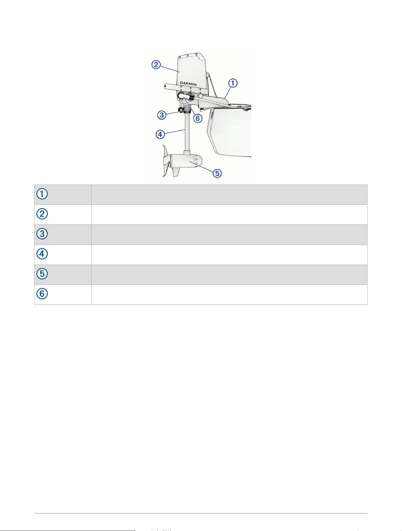
Getting Started
Mount
Steering system
Depth adjustment collar
Shaft
Propeller drive motor
Power cable connector
2 Getting Started
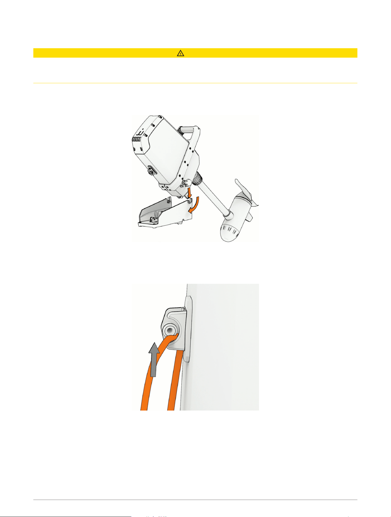
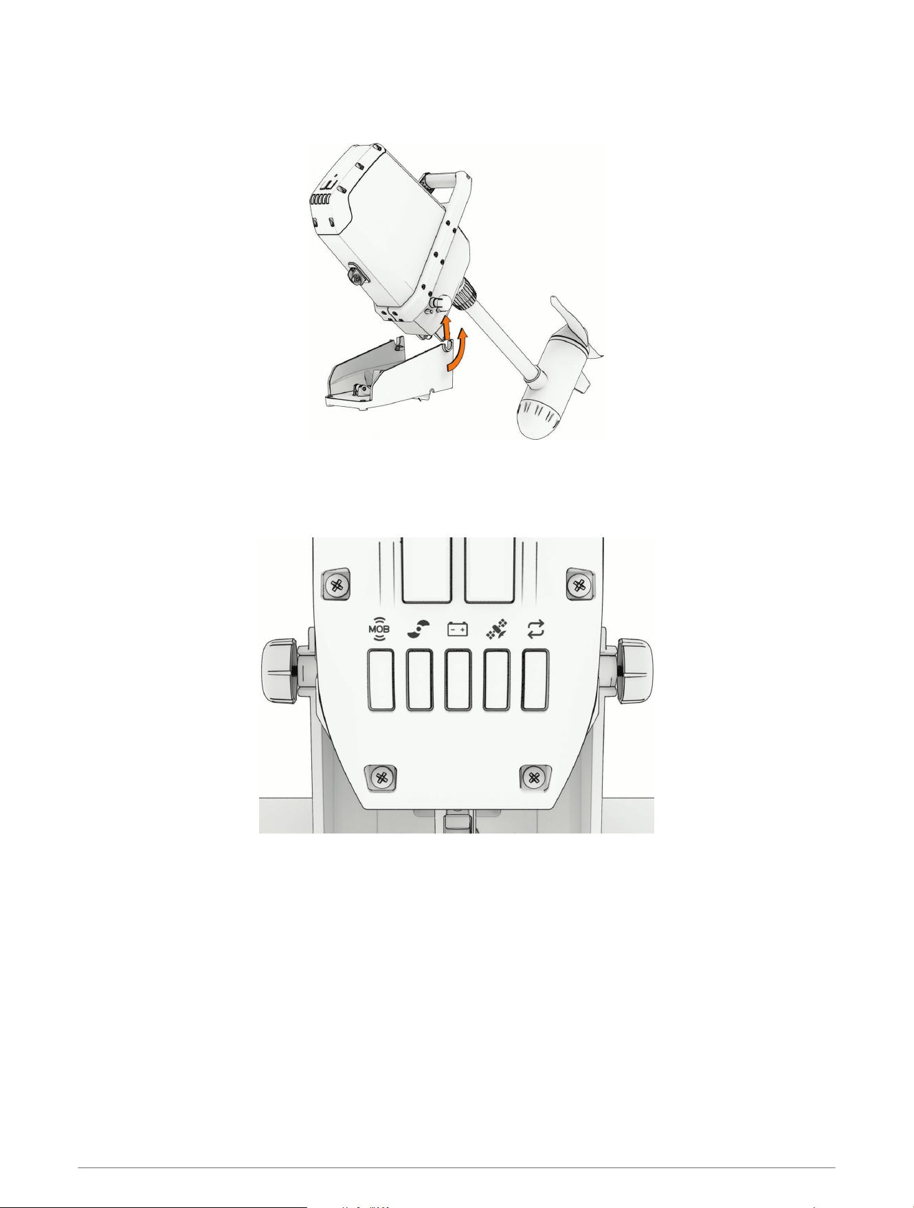
Installing the Motor on the Mount
CAUTION
When transporting the trolling motor, always use the handle on the back of the steering system housing and be
mindful of the propeller drive motor and the propeller, to prevent the possibility of personal injury or property
damage.
1 If necessary, loosen the pivot knobs on both sides of the trolling motor.
2 Lower the motor onto the mount at an approximately 45-degree angle, matching the pivot knobs on the
motor with the pivot brackets on the mount.
3 Allow the motor to pivot down to a vertical position.
4 Tighten the knobs on either side of the motor until they stop.
5 Start the pull rope partly into the eyelet on the front of the motor steering system, and pull the upper part of
the rope up until it slips into the eyelet.
Getting Started 3
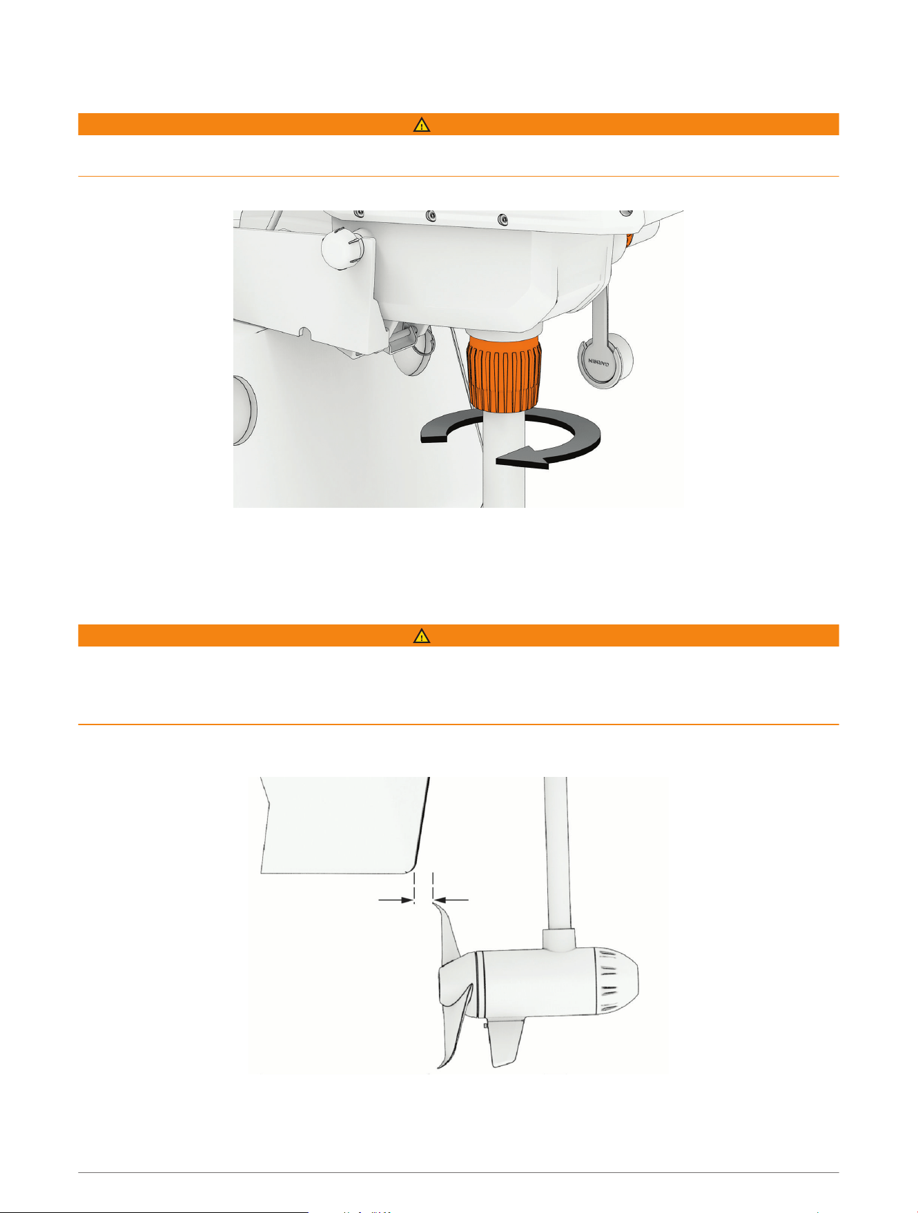
Adjusting the Depth of the Trolling Motor
WARNING
Before you set the motor depth, you must make sure there is enough clearance for the propeller throughout the
rotation of the motor shaft (Checking the Propeller Clearance, page4).
1 Loosen the collar at the base of the steering system housing.
2 Raise or lower the depth of the trolling motor.
3 After you have set the motor to the desired depth, tighten the collar at the base of the steering system
housing.
Checking the Propeller Clearance
WARNING
Before turning on the trolling motor, you must make sure there is enough clearance between the propeller and
the hull through the entire rotation of the motor shaft. Installing the motor with insufficient space between the
propeller and the hull may result in personal injury and property damage if the propeller contacts the hull during
use.
1 Rotate the propeller drive motor manually to check the clearance through a complete 360-degree rotation of
the shaft.
2 If necessary, adjust the motor depth to ensure sufficient space between the propeller and the hull (Adjusting
the Depth of the Trolling Motor, page4).
4 Getting Started
Connecting to Power
WARNING
To avoid possible serious personal injury or property damage, the circuit breaker must be in the off position
before you connect the trolling motor power cable to it.
You must connect the positive (+) wire on the power cable through a circuit breaker or a fuse rated for 40A
(continuous). Connecting this wire to power without a circuit breaker or fuse could result in a short on the wire,
which may lead to overheating and a possible fire.
NOTICE
You must connect the Force Current trolling motor to a 12 or 24Vdc battery. Connecting the motor to other
voltages may cause poor performance or product damage.
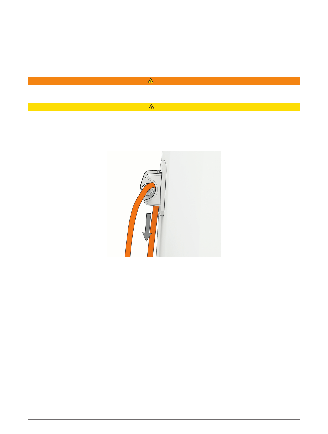
1 Connect the trolling motor power cable to the battery, routing the red (+) wire through a circuit breaker rated
for 40A (continuous).
2 Turn the weather cap on the trolling motor power connector a quarter-turn counterclockwise to expose the
power connector.
3 Insert the power cable connector, with the cable approximately parallel to the kayak, and push until it is fully
inserted.
NOTE: Make sure the locking collar on the power cable connector is in the unlock position, before connecting
it to the motor.
The power cable strain relief rests against the cradle on the motor housing.
4 Turn the locking ring on the power cable connector a quarter-turn clockwise to lock it in place.
Getting Started 5
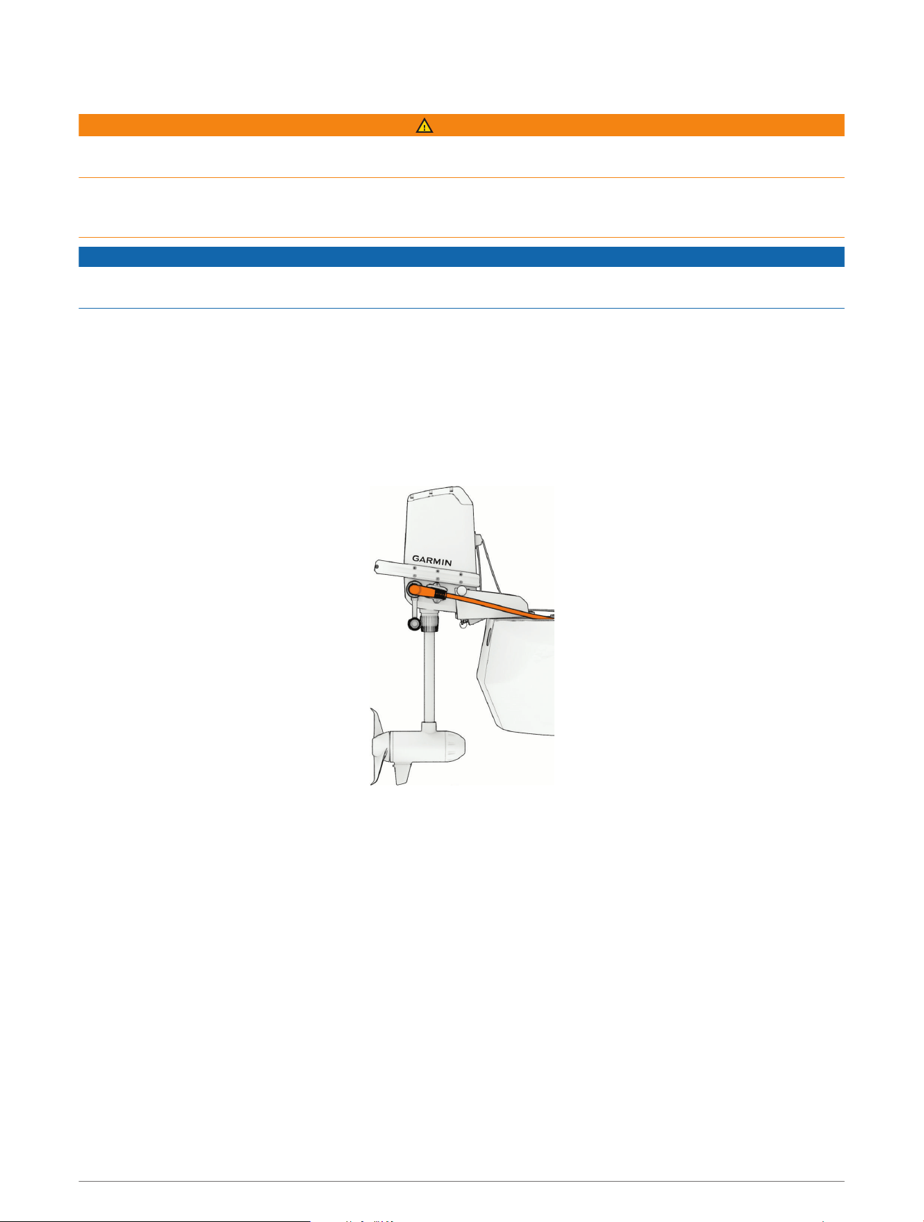
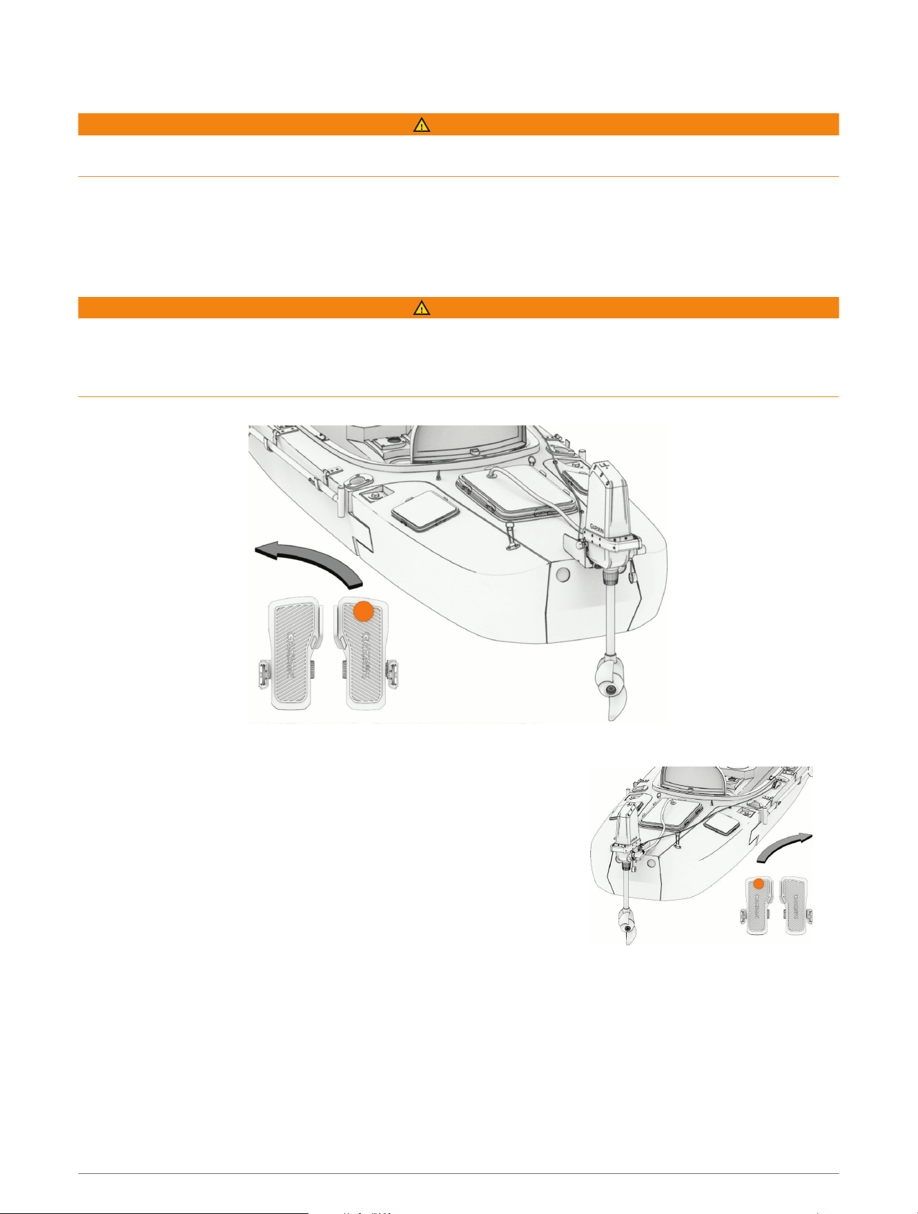
Stowing the Motor
1 Pull the rope handle toward the motor, lifting the propeller drive motor out of the water.
2 Lower the rope so that it catches in the cleat, and gently release the tension.
The rope is secure under tension in the cleat, holding the motor in the stowed position.
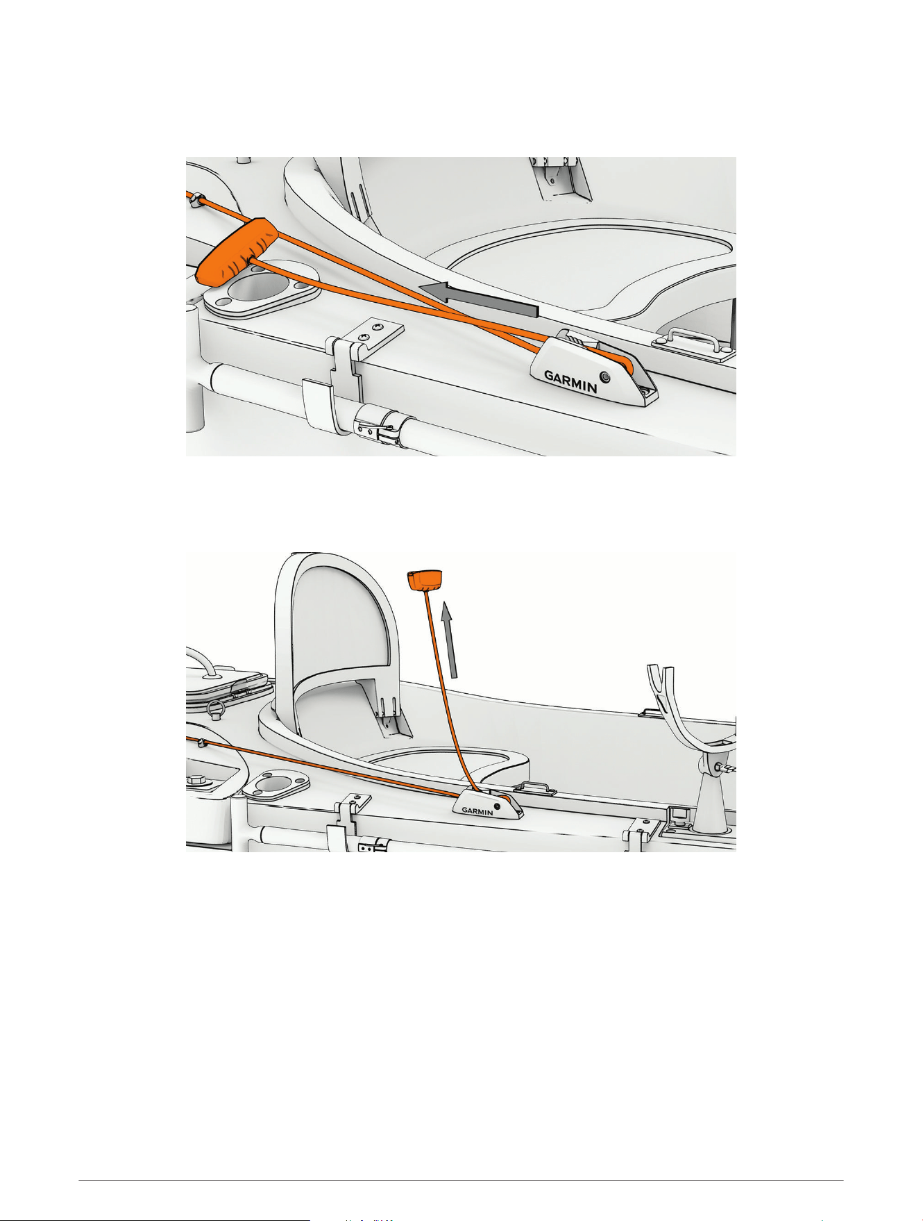
Deploying the Motor
1 Pull the handle up and back to release the rope from the cleat.
2 Gently release the tension on the rope to lower the propeller drive motor into the water until it stops.
The mount latch engages the locking pin, holding the motor in the deployed position.
6 Getting Started
Removing the Motor from the Mount
You must switch off the circuit breaker and disconnect the power cable from the motor before removing the
motor from the mount.
You must trasition the motor to the deployed position (Deploying the Motor, page6), or release the rope from the
cleat and support the motor using the handle on the back of the steering system housing, before removing the
motor from the mount.
WARNING
You must remove the trolling motor from the kayak before transporting the kayak. Transporting the kayak with
the trolling motor on the mount may lead to an accident causing serious personal injury and property damage.
CAUTION
When transporting the trolling motor, always use the handle on the back of the steering system housing and be
mindful of the propeller drive motor and the propeller, to prevent the possibility of personal injury or property
damage.
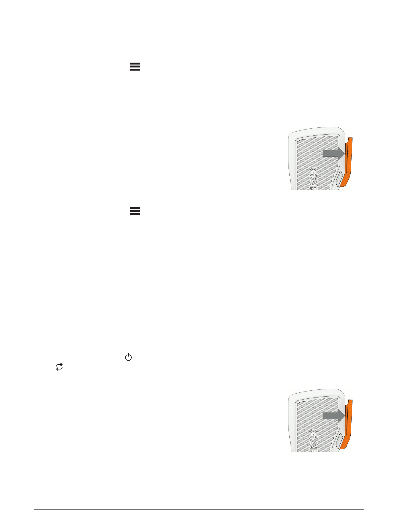
1 Pull the top of the rope partly out of the open side of the eyelet on the front of the motor steering system, and
pull the lower part of the rope down until it slips out of the eyelet.
2 Unscrew the knobs on both sides of the motor until they stop.
Getting Started 7
3 Tilt the motor up to an approximately 45-degree angle using the handle on the back of the motor.
If the motor is in the deployed position, you must pull the rope up to release the mount latch before you can
tilt the motor.
4 Lift the motor off of the mount using both hands.
Status Indicator
The status LEDs on the top panel of the trolling motor indicate the status of the motor.
8 Getting Started
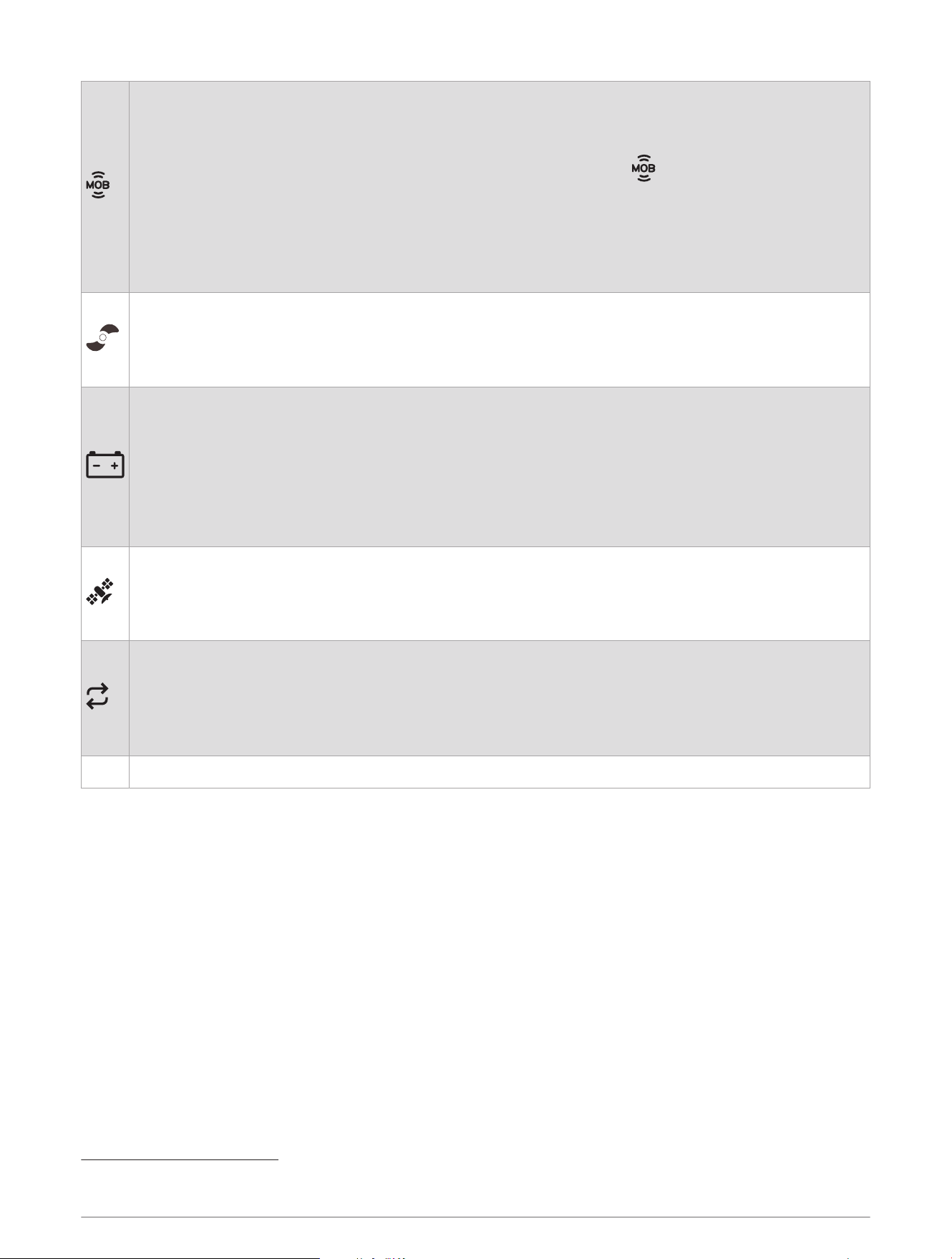
Man Overboard (MOB) tag (MOB Tag, page26):
• Solid green: MOB tag is connected.
• Flashing red: MOB tag connection has been lost. The propeller is disabled.
NOTE: After the MOB tag connection is restored, you must press the button on the MOB tag, or
dismiss the notification on the remote control or on a connected chartplotter, before you can turn on
the propeller.
• Solid red: MOB tag is not connected. The propeller is disabled.
• Flashing yellow: MOB tag is not connected, and MOB Tag Override Mode is on. The propeller is not
disabled (Overriding the MOB Tag, page27).
Propeller and autopilot status:
• Solid green: The propeller is on.
• Flashing green: Autopilot mode is enabled.
• Off: The propeller is off.
Battery status:
• Solid green: The battery level is good.
• Solid yellow: The battery level is medium.
• Solid red: The battery level is low.
• Flashing red: The battery level is critically low.
NOTE: By default, the battery level indicator is optimized for lithium iron phosphate batteries (Battery
Management Settings, page25).
GPS status:
• Solid green: The motor has a good GPS signal.
• Solid yellow: The motor has a poor GPS signal.
• Solid red: The motor does not have GPS signal.
Status:
• Solid green: There are no errors.
• Solid blue: The motor is in pairing mode.
• Solid red: An error has occurred
1
.
• Flashing red: A critical error has occurred.
All Alternating flashing green: The motor, remote control, or foot pedals are installing a software update.
1
After resolving the error, you may need to turn the motor off and back on again to clear the red error LED.
Getting Started 9
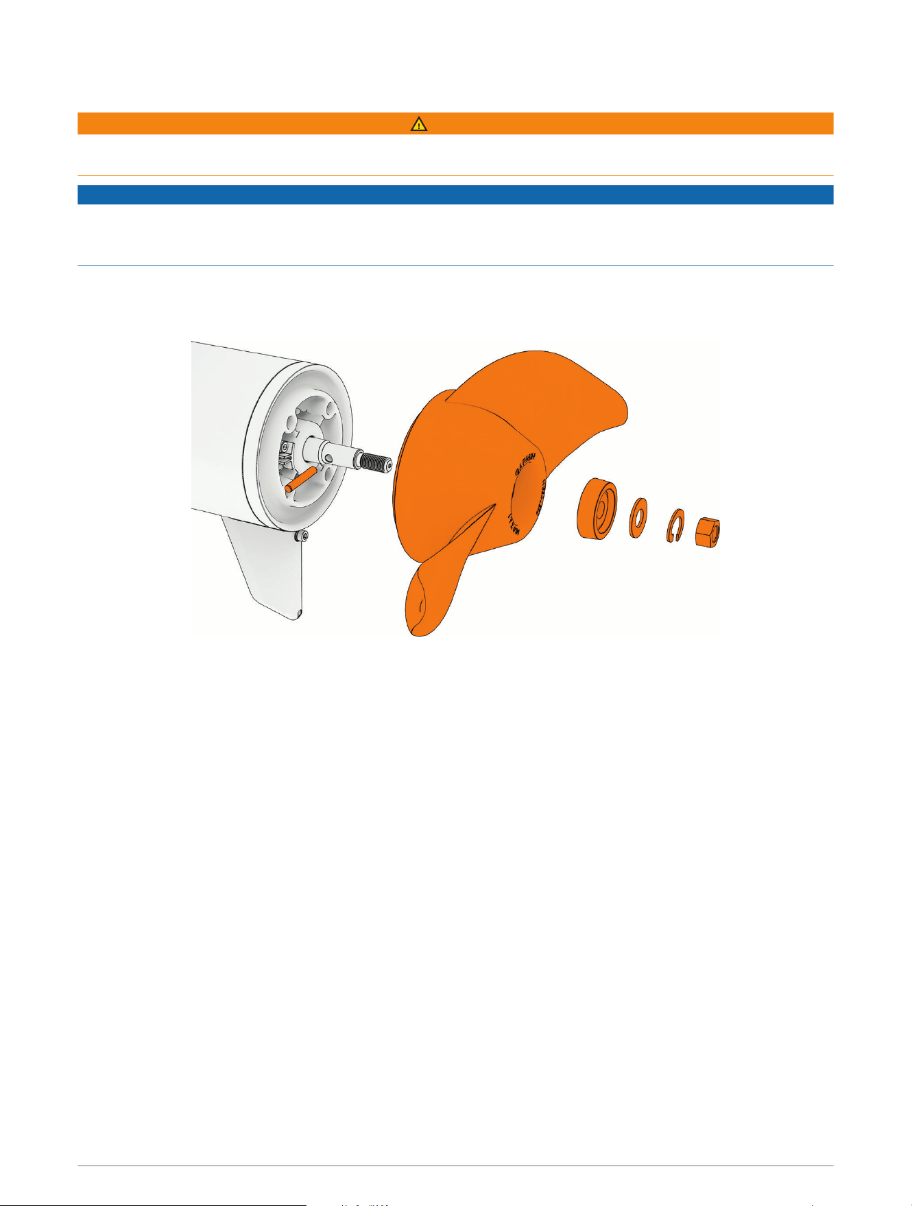
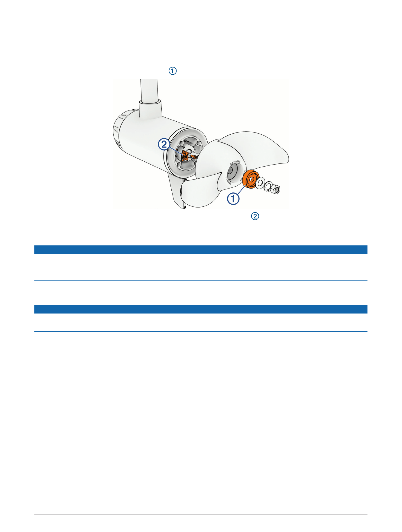
Changing the Propeller
WARNING
Always disconnect the motor from the battery before handling or working with the propeller to avoid serious
injury or death.
NOTICE
You should use the Force Current trolling motor with the high-efficiency propeller only in open-water conditions.
When using the high-efficiency propeller in shallow water conditions, there is an increased risk of damaging the
propeller if the motor collides with an underwater obstacle.
The Force Current trolling motor includes a high efficiency propeller and a weedless propeller. Follow these
steps when changing propellers.
1 Using a
9
/
16
in (15mm) socket, remove the nut that secures the propeller.
2 Remove the propeller and set aside the lock washer, flat washer and sacrificial anode.
3 Make sure the pin in the propeller motor shaft is in place, and replace it if necessary.
4 Install the new propeller.
5 Place the anode, flat washer, lock washer, and nut back on the propeller drive shaft.
6 Using a
9
/
16
in (15mm) socket, tighten the nut to 16.27N-m (12lbf-ft) to secure the propeller.
10 Getting Started
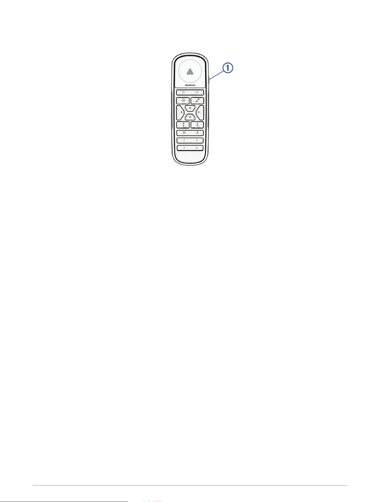
Remote Control
Remote Control 11
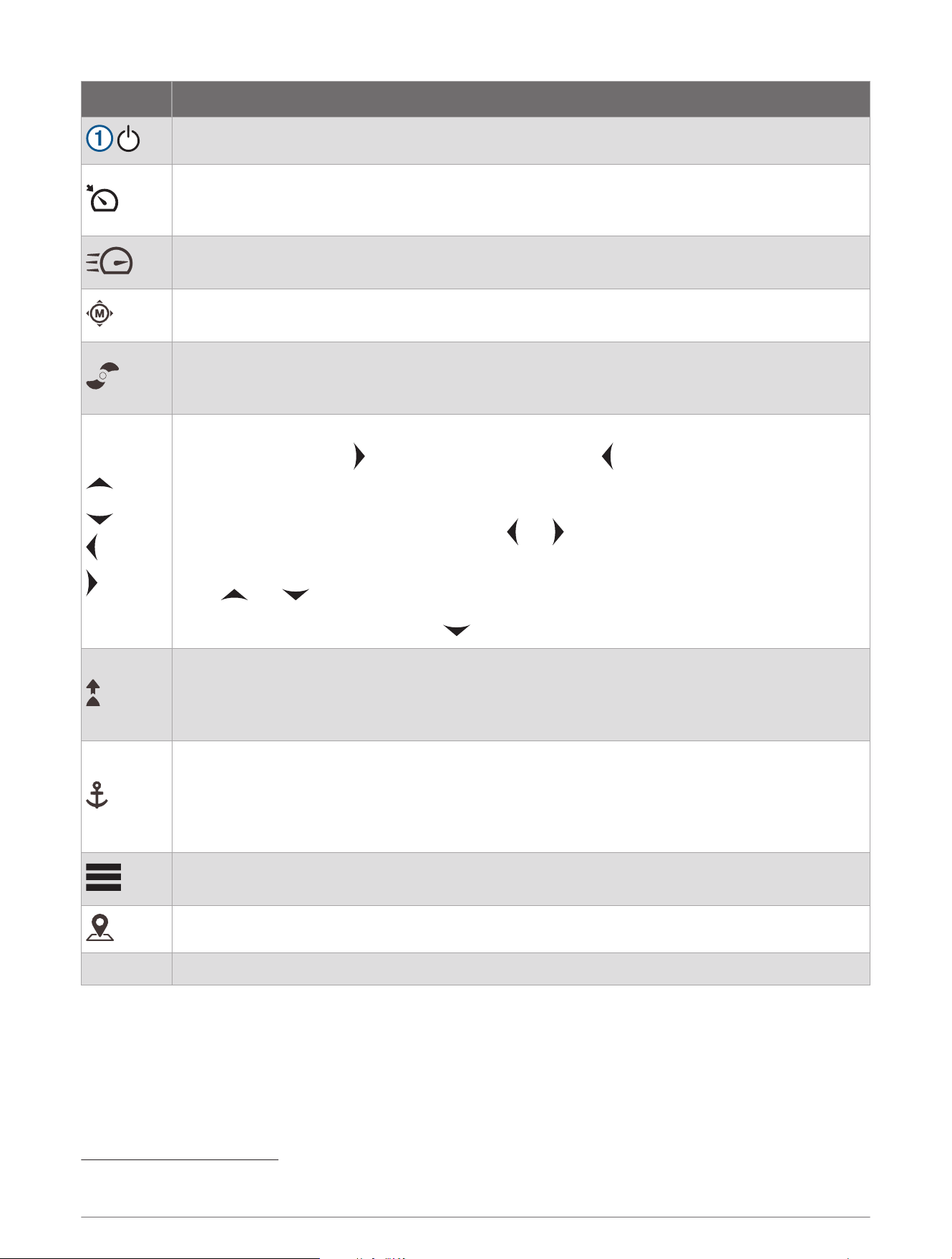
Button Description
Hold to turn the remote control on and off.
Press to turn on and set cruise control at the current speed over ground (SOG) (Maintaining Your
Speed, page22).
Press again to disable cruise control and return to manual speed control.
Press twice to turn on the propeller and set it to full speed.
Press again to return to the previous speed and propeller state.
Press for manual control (Steering the Trolling Motor Manually, page17).
Hold to steer using gestures (Using Gesture Controls to Steer, page14).
Press once to turn the propeller on or off (Turning the Propeller On and Off, page16).
Press twice to turn off any autopilot function (if enabled), stop the propeller, and shift between
forward and reverse thrust (Reverse Thrust, page17).
Press to navigate the menu (Navigating the Menu, page14).
When in the menu, press to select a menu item, and press to go back without saving.
When in anchor lock, press to jog the anchor lock position forward, backward, left, or right in
1.5m (5ft.) increments.
When in heading hold or manual control, press and for single-degree step turns, or hold for
steering in five-degree increments.
Press and for incremental speed changes, or hold for continuous speed changes.
When your speed is set to zero, press to shift into reverse (Reverse Thrust, page17).
Press to turn on heading hold. Heading hold uses the trolling motor to maintain your current
heading (Maintaining Your Heading, page23).
Press again to turn off heading hold, stop the propeller, and resume manual control.
Hold to set the heading hold by pointing the remote (Gesture Controls, page14).
Press to turn on anchor lock. Anchor lock uses the trolling motor to hold your position (Holding
Your Position, page22).
Press again to turn off anchor lock and return to the previous steering mode.
Hold to jog the anchor lock position by pointing the remote (Using Gesture Controls to Adjust Your
Held Position, page14).
Press to open the menu.
Press to exit the menu.
Press to mark a waypoint.
1 through 4 Press to open the shortcut for the Garmin
®
chartplotter assigned to the button.
2
2
Requires a connection to a compatible Garmin chartplotter. See your chartplotter owner's manual for instructions.
12 Remote Control
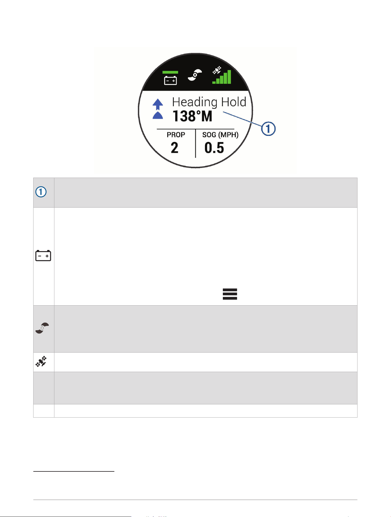
Remote Control Screen
Shows the operational status of the trolling motor.
For example, when in manual control, Manual is shown, and when the heading hold is on, Heading Hold
is shown, along with the heading-hold set point in degrees.
Shows the trolling motor battery status.
Green: the motor battery voltage level is good.
Yellow: the motor battery voltage level is medium.
Red: the motor battery voltage level is low.
Flashing red: the motor battery voltage level is critically low.
NOTE: By default, the battery level indicator is optimized for lithium iron phosphate batteries (Battery
Management Settings, page25).
TIP: You can change the appearance of the trolling motor battery status so that it shows a numeric
voltage instead of an icon (Trolling Motor Settings, page24).
You can view the remote control battery level by pressing .
Shows the status of the propeller.
White and rotating: the propeller is providing a forward thrust.
Red and rotating: the propeller is providing a reverse thrust.
3
Not rotating: the propeller is on with the speed set to zero.
Not shown: the propeller is off.
Shows the GPS signal strength of the trolling motor.
PROP
Shows the speed level of the propeller (Adjusting the Speed of the Motor, page16).
When the propeller is actively providing a reverse thrust, the speed level is shown in red.
4
NOTE: The propeller speed is not shown when the motor is using cruise control.
SOG Shows the measured speed over ground (SOG).
3
The motor may run louder in reverse thrust than in forward thrust.
4
In reverse thrust, the motor runs louder, produces less thrust, and is less efficient than in forward thrust.
Remote Control 13

Navigating the Menu
You can use the menu and arrow keys to navigate the menu on the remote control.
• To open the menu, press .
• To move between different menu items, press and .
• To select a menu item, press .
• To move back to a previous menu item, press .
• To exit the menu, press , or press repeatedly until you reach the main screen.
Gesture Controls
You can point or move the remote control to interact with the trolling motor. You must calibrate the compass
in the trolling motor (Calibrating the Trolling Motor Compass, page21), and the compass in the remote control
(Calibrating the Remote Control, page15) before you can use gesture controls.
Using Gesture Controls to Steer
You can steer the motor by pointing the remote control.
1 If necessary, turn on the propeller (Turning the Propeller On and Off, page16).
2 Hold .
3 While holding , point the remote control to the left or right to steer port or starboard.
4 Release to stop steering.
Using Gesture Controls to Adjust the Heading Hold
You can move the remote control to adjust your heading hold (Maintaining Your Heading, page23).
1 If necessary, turn on the propeller (Turning the Propeller On and Off, page16).
2 Hold .
3 Point the remote control toward where you want to adjust the heading.
4 Release to set the heading direction.
Using Gesture Controls to Adjust Your Held Position
You can move the remote control to adjust your position when using the anchor lock feature (Holding Your
Position, page22).
1 Hold .
2 Point the remote control in the direction you want to move your position.
Your position jogs 1.5m (5ft.) in the direction you point.
3 Release .
4 Repeat this procedure until the you are in the position you want.
Installing Batteries in the Remote Control
The remote control operates using two AA batteries (not included). Use lithium batteries for best results.
1 Turn the D-ring counter-clockwise, and pull up to remove the cover.
2 Insert two AA batteries, observing polarity.
3 Replace the battery cover, and turn the D-ring clockwise.
14 Remote Control
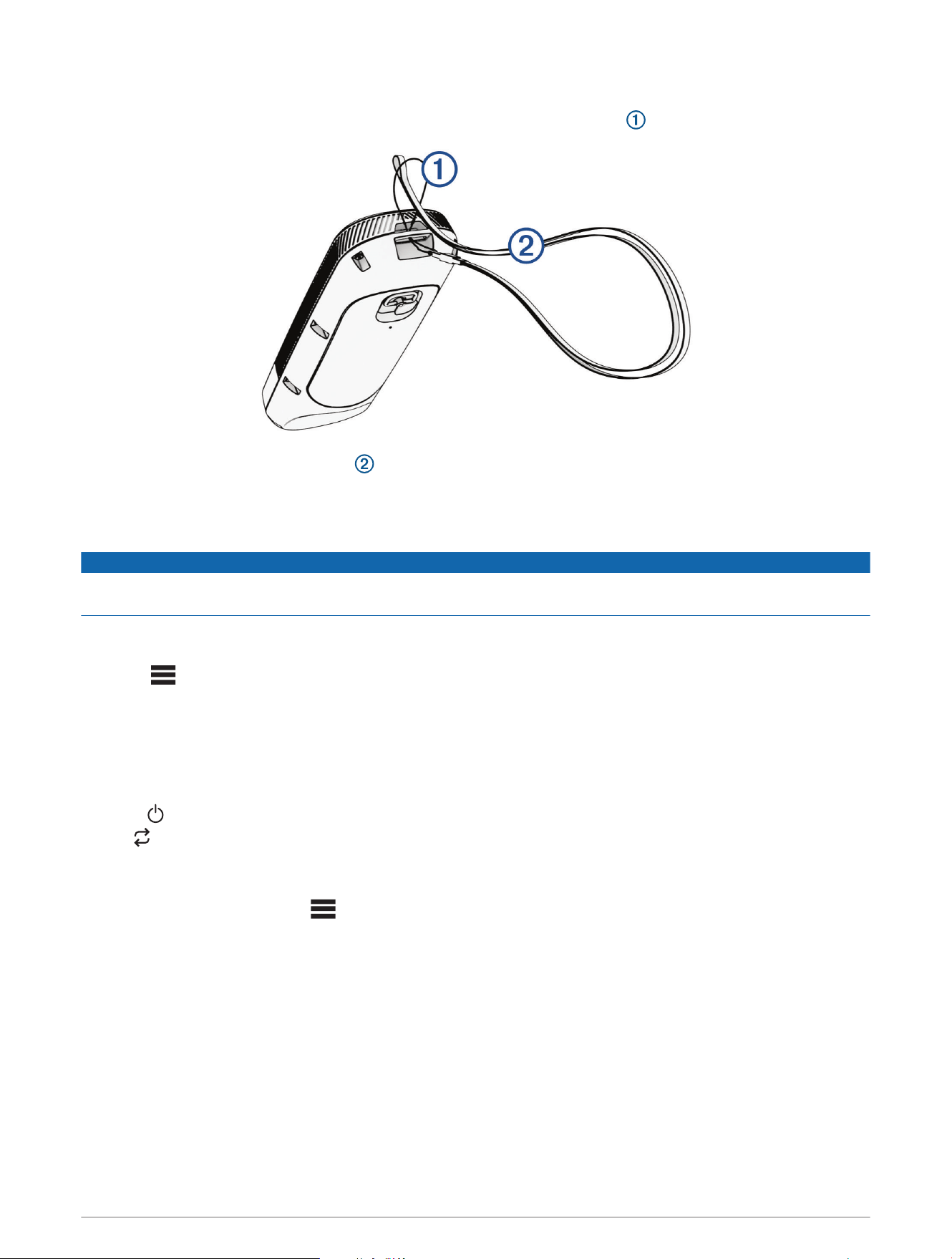
Attaching a Lanyard
1 Starting from the back of the remote control, insert the loop of the lanyard through the slot.
2 Thread the other end of the lanyard through the loop, and pull it tight.
3 If necessary, place the lanyard around your neck or wrist to tether it during use.
Calibrating the Remote Control
NOTICE
Calibrate the electronic compass outdoors. To improve heading accuracy, do not stand near objects that
influence magnetic fields, such as vehicles, buildings, and overhead power lines.
You must calibrate the compass in the remote control before you can control the motor using gestures. If the
gesture controls are not working properly after calibration, you can repeat this process as often as needed.
1 Select > Settings > Remote Control > Calibrate.
2 Select Start, and follow the on-screen instructions.
Pairing the Remote Control
The remote control is paired with the trolling motor at the factory. Follow these steps if you need to pair it again.
1 Turn on the trolling motor.
2 Press on the trolling motor three times to enter pairing mode.
The status LED on the trolling motor illuminates blue as it searches for a connection.
3 Bring the remote control within 1m (3ft.) of the trolling motor.
4 Turn on the remote control.
5 On the remote control, select > Settings > Remote Control > Pairing > Pair > Start.
After a few seconds, Pairing Complete is shown on the remote control.
Remote Control 15

Pairing an Additional Remote Control
You can have up to two remote controls connected to your trolling motor at the same time.
To pair a second remote control, you must follow these steps using the first connected remote control.
1 Turn on the trolling motor.
2 On a remote control already paired to the motor, select > Settings > Remote Control > Pairing > Add
Additional Remote.
3 Bring the additional remote control within 1m (3ft.) of the display panel on the trolling motor.
4 Turn on the additional remote control.
5 On the additional remote control, select > Settings > Remote Control > Pairing > Pair > Start.
Device Found appears on the first remote control. After a few seconds, Pairing Complete appears on the
second remote control.
Operation
You can operate every feature of the trolling motor using the included remote control (Remote Control, page11).
In addition to the remote control, you can control certain features of the Force Current trolling motor using any
of the following devices:
• the Power Steer foot pedals, included with some models (Power Steer Foot Pedals, page29).
• a mobile device with the ActiveCaptain
®
app (Connecting to a Mobile Device with the ActiveCaptain App,
page33).
• a compatible Garmin chartplotter (Connecting to a Chartplotter, page34).
5
• a compatible Garmin watch (Connecting to a Garmin Watch, page34).
For details on controlling the trolling motor using a watch or a chartplotter, see the Owner's Manual for the
specific device.
Turning the Propeller On and Off
WARNING
Do not use the motor in areas where you or other people in the water may come into contact with the rotating
propeller, which could result in severe injury.
Do not run the motor when the propeller is out of the water. Contact with the rotating propeller may result in
severe injury.
1 If necessary, deploy the trolling motor (Deploying the Motor, page6).
NOTE: The propeller cannot turn on when the trolling motor is in the stowed position.
2 On the remote control, press to turn on the propeller.
3 Press again to turn off the propeller.
Adjusting the Speed of the Motor
On the remote control, press or to increase or decrease your speed.
In manual mode, the propeller speed, shown in the PROP field on the remote control screen, increases or
decreases accordingly.
In cruise control mode, the current target speed is displayed on the trolling motor remote screen, and it
increases or decreases accordingly.
NOTE: In manual mode, increasing or decreasing the speed using the remote control does not automatically
turn the propeller on. You must press the button on the remote control to turn on the propeller.
5
Some ECHOMAP
™
Ultra and ECHOMAP UHD chartplotters that no longer receive software updates do not support some features of the Force Current trolling
motor. You must use the trolling motor remote for initial set-up.
16 Operation
Toggling Full Speed
1 On the remote control, press twice.
The trolling motor propeller speed quickly increases to full speed.
2 Press to return to the previous propeller speed.
TIP: When at full speed, you can press on the remote control to slowly decrease the propeller speed.
Operating the Propeller When Partially Deployed
WARNING
Do not run the motor when the propeller is out of the water. Contact with the rotating propeller may result in
severe injury.
You should only operate the trolling motor propeller with the motor partially deployed in limited circumstances,
such as passing over weeds or submerged obstacles. Otherwise, you or someone else could come into contact
with the rotating propeller, which could cause severe injury.
CAUTION
Before lifting the motor partly out of the water, you must press on the remote control to make sure the
motor is in manual mode. Lifting the motor out of the water while it is running in an autopilot mode may cause
unexpected movement of the motor or kayak, possibly causing personal injury or property damage.
NOTICE
You should use the Force Current trolling motor with the high-efficiency propeller only in open-water conditions.
When using the high-efficiency propeller in shallow water conditions, there is an increased risk of damaging the
propeller if the motor collides with an underwater obstacle.
1 With the trolling motor in the deployed position, pull the rope handle slowly to lift the motor until it is in
position to pass over the weeds or obstacle.
If you lift the motor too far out of the water, the propeller turns off automatically.
2 Turn the propeller on and set the propeller speed as needed to move the boat past the obstruction.
3 When you are past the obstacle, slowly lower the motor back to the deployed position.
Steering the Trolling Motor Manually
Manual mode is the default operational mode of the trolling motor. In manual mode, you can adjust the direction
and speed of the trolling motor as needed.
NOTE: The trolling motor is in manual mode by default when you turn it on.
1 If necessary, on the remote control, select .
2 Select an action:
• Using the remote control, press and to steer.
NOTE: You can also use gesture controls to steer the boat manually using the remote control (Using
Gesture Controls to Steer, page14).
• Using the foot pedal, push the pedal with your toes and heel to steer.
Reverse Thrust
In manual mode, you can run the propeller in reverse. Running the propeller in reverse for short periods of time
can be useful in some situations, such as backing out of a tight space with less steering of the motor.
Because the propeller on the trolling motor is designed primarily for forward thrust, it is less efficient at
creating reverse thrust, resulting in more noise from the motor, especially at higher propeller speeds, and more
turbulence underwater.
NOTICE
You should use reverse thrust sparingly to minimize cavitation and excessive wear on the propeller and the
propeller drive motor.
Operation 17
Shifting Between Forward and Reverse Mode
1 Press twice.
The icon on the remote control screen turns red when the propeller is set to reverse. If the motor
is running in an autopilot mode, it automatically switches to manual mode. If the propeller is running, it
automatically stops.
2 Press again to turn the propeller on.
NOTE: When shifting between forward and reverse mode, the propeller speed is automatically set to the last
speed you used in the same thrust mode.
Waypoints
Waypoints are used to mark locations so you can return to them later. The trolling motor can store up to 5000
waypoints.
When the trolling motor is connected to a chartplotter, the waypoints stored on the trolling motor and on the
chartplotter are automatically synchronized.
NOTE: Because the systems are synchronized, when you delete waypoints, restore default settings, or clear user
data using the trolling motor remote, the waypoints on the chartplotter are also deleted. Likewise, if you delete a
waypoint from the chartplotter, it is automatically deleted from the trolling motor.
Creating a Waypoint
You can save your current location as a waypoint.
1 If necessary, drive to a location you want to save as a waypoint.
2 On the remote control, press .
Navigating to a Waypoint
1 On the remote control, select > Waypoints.
A list of the ten closest waypoints is shown.
2 Select a waypoint.
3 Select Navigate To.
4 Turn on the propeller (Turning the Propeller On and Off, page16).
The trolling motor drives to the waypoint location (Navigating, page23).
Viewing Waypoint Details
1 On the remote control, select > Waypoints.
A list of the ten closest waypoints is shown.
2 Select a waypoint.
3 Select Review.
Editing a Waypoint Name
1 On the remote control, select > Waypoints.
A list of the ten closest waypoints is shown.
2 Select a waypoint.
3 Select Edit.
4 Enter a new name for the waypoint.
Deleting a Waypoint
1 On the remote control, select > Waypoints.
A list of the ten closest waypoints is shown.
2 Select a waypoint.
3 Select Delete.
18 Operation

Routes
A route is a sequence of locations that leads you to your final destination.
When you connect the trolling motor to a chartplotter, the routes stored on the chartplotter are synchronized
with the routes stored on the trolling motor. Deleting or editing routes on one device automatically changes the
routes stored on the other device. You can create routes on the chartplotter only.
You can save up to 100 routes.
Navigating a Route
1 On the remote control, select > Routes.
A list of the ten closest routes is shown.
2 Select a route.
3 Select Navigate To.
4 Select an option:
• To navigate the route from the starting point used when the route was created, select Forward.
• To navigate the route from the destination point used when the route was created, select Backward.
• To navigate from your current location to the beginning of the route, then navigate the route, select From
Start.
5 Turn on the propeller (Turning the Propeller On and Off, page16).
The trolling motor drives along the route in the chosen direction (Navigating, page23).
As you approach the end of the route, by default, the trolling motor switches to the anchor lock feature and
holds position at the end of the route. You can change this behavior in the settings (Trolling Motor Settings,
page24).
Viewing Route Details
1 On the remote control, select > Routes.
A list of the ten closest routes is shown.
2 Select a route.
3 Select Review.
Editing a Route Name
1 On the remote control, select > Routes.
A list of the ten closest routes is shown.
2 Select a route.
3 Select Edit.
4 Enter a new name for the route.
Deleting a Route
1 On the remote control, select > Routes.
A list of the ten closest routes is shown.
2 Select a route.
3 Select Delete.
Tracks
A track is a recording of the path of your boat. The track currently being recorded is called the active track, and it
can be saved. You can save up to 50 tracks.
When you connect the trolling motor to a chartplotter, the active track and saved tracks stored on the
chartplotter are synchronized with the active track and saved tracks stored on the trolling motor. Adding,
deleting, or editing active and saved tracks on one device automatically changes the active and saved tracks
stored on the other device.
Operation 19

Saving the Active Track
The track currently being recorded is called the active track. You can save the active track and navigate it later.
You can save up to 50 tracks on the trolling motor.
1 On the remote control, select > Tracks > Save Active Track.
The active track is saved with the current date as the track name.
2 Change the name for the saved track (optional).
Clearing the Active Track
Select > Tracks > Clear Active Track.
The track memory is cleared, and the active track continues to be recorded.
Navigating to the Start of the Active Track
The track currently being recorded is called the active track. You can navigate from your current position back to
the starting point of the active track along the path you traveled.
1 Select > Tracks > Backtrack.
2 Turn on the propeller (Turning the Propeller On and Off, page16).
The trolling motor navigates back to the starting point of the active track along the path you traveled
(Navigating, page23).
Navigating a Saved Track
1 Select > Tracks > Saved Tracks.
A list of the ten closest saved tracks is shown.
2 Select a saved track.
3 Select Navigate To.
4 Select an option:
• To navigate the saved track from the beginning of the track to the end, select Forward.
• To navigate the saved track from the end of the track back to the beginning, select Backward.
5 Turn on the propeller (Turning the Propeller On and Off, page16).
The trolling motor drives along the saved track in the chosen direction (Navigating, page23).
Viewing Saved Track Details
1 On the remote control, select > Tracks > Saved Tracks.
A list of the ten closest saved tracks is shown.
2 Select a saved track.
3 Select Review.
Editing a Saved Track Name
1 On the remote control, select > Tracks > Saved Tracks.
A list of the ten closest saved tracks is shown.
2 Select a saved track.
3 Select Edit.
4 Enter a new name for the saved track.
Deleting a Saved Track
1 On the remote control, select > Tracks > Saved Tracks.
A list of the ten closest saved tracks is shown.
2 Select a saved track.
3 Select Delete.
20 Operation

Autopilot
WARNING
You are responsible for the safe and prudent operation of your vessel. The autopilot features on the trolling
motor are tools that enhance your capability to operate your boat. They do not relieve you of the responsibility
of safely operating your boat. Avoid navigational hazards and never leave the motor controls unattended.
Before activating any autopilot function, make sure the motor is fully in the deployed position, and the mount
latch is engaged. Activating an autopilot function before the motor is latched in the deployed may lead to
unexpected kayak movement, resulting in possible serious personal injury or property damage.
Learn to operate the autopilot features on calm and hazard-free open water.
CAUTION
When using the autopilot features, be prepared for sudden stops, acceleration, and turns.
The Force Current trolling motor supports autopilot features such as following a pre-planned route, maintaining
your kayak's heading, and holding your position.
You must calibrate the trolling motor compass before you can use the autopilot features (Calibrating the Trolling
Motor Compass, page21). You must have a GPS signal to activate an autopilot mode (Acquiring a GPS Signal,
page22).
You can activate and control autopilot modes using the remote control (Remote Control, page11), the Power
Steer foot pedals (Using the Foot Pedal Levers, page32), a chartplotter, a mobile device with the ActiveCaptain
app, or a compatible Garmin watch. See the Owner's Manual at garmin.com/manuals/force_current_trolling
_motor for more information on autopilot features.
TIP: In some situations, the autopilot modes can create more turbulence than expected. You can adjust the
autopilot gain settings to tailor the autopilot sensitivity to different conditions (Adjusting the Autopilot Response,
page22).
The Force Current supports the following autopilot features:
Cruise Control: The motor automatically controls the propeller speed to maintain a target speed (Maintaining
Your Speed, page22).
Anchor Lock: The motor automatically steers and runs the propeller to maintain your position (Holding Your
Position, page22).
Heading Hold: The motor steers automatically to keep your boat in the same heading (Maintaining Your
Heading, page23).
Route Following: The motor can steer and run the propeller automatically to navigate to a waypoint or along a
course or a track (Navigating, page23).
Calibrating the Trolling Motor Compass
Before calibrating the trolling motor compass, you must move to an open area of calm water, with enough
space to maneuver the kayak in a circle.
NOTICE
Calibrating the trolling motor compass in rough water and wind conditions may negatively affect autopilot
performance.
1 Make sure the trolling motor is in the deployed position (Deploying the Motor, page6).
2 On the remote control, select > Settings > Trolling Motor > Calibrate > Compass.
3 When prompted, follow the on-screen instructions to calibrate the compass.
NOTICE
While calibrating the compass, you should use the trolling motor to steer the kayak at low speed. Using a
paddle to steer the kayak to calibrate the compass may cause excessive movement, leading to poor autopilot
performance.
If the autopilot features do not perform as expected, you should repeat the calibration process.
Autopilot 21

Acquiring a GPS Signal
1 Move the kayak to an area with an unobstructed view of the sky.
2 Wait 30 to 60 seconds while the trolling motor locates satellites.
When the motor has acquired a position using GPS, the LED indicator light is solid green.
Adjusting the Autopilot Response
You can adjust the autopilot gain setting to tailor the autopilot sensitivity to different conditions.
1 On the remote control, select > Settings > Trolling Motor.
2 Select an option:
• To adjust the gain for Anchor Lock mode, select Anchor Gain.
• To adjust the autopilot gain for navigation modes, including Heading Hold and Cruise Control, select
Navigation Gain.
3 Select or to increase or decrease the gain value:
• Increase the gain setting to make the autopilot more responsive. The motor will be more accurate in
controlling your kayak, but it may create more turbulence. Higher gain values are typically needed for
larger or heavier boats.
• Decrease the gain setting to make the autopilot less responsive. The motor will create less turbulence, but
it may be less accurate in controlling your kayak.
Maintaining Your Speed
Before you can use autopilot features, you must calibrate the trolling motor (Calibrating the Trolling Motor
Compass, page21).
The cruise control feature is an autopilot function that sets and maintains a specific speed over ground,
adjusting for changes in current and wind automatically.
TIP: You can use cruise control alongside other autopilot modes (Autopilot, page21).
On the remote control, press .
Cruise control is enabled at the present speed.
To turn off cruise control and turn off the propeller, you must press .
Holding Your Position
Before you can use autopilot features, you must calibrate the trolling motor (Calibrating the Trolling Motor
Compass, page21).
The anchor lock feature uses GPS to maintain your position using the trolling motor.
Press .
NOTE: You can adjust the anchor lock position by pressing an arrow key on the remote control, or by using
gesture controls (Using Gesture Controls to Adjust Your Held Position, page14).
To disable anchor lock, press again.
22 Autopilot

Maintaining Your Heading
Before you can use autopilot features, you must calibrate the trolling motor (Calibrating the Trolling Motor
Compass, page21).
You can activate Heading Hold to keep your boat moving in the same compass direction. The motor may adjust
your heading automatically to compensate for drift caused by factors such as wind and currents.
1 Steer the boat in the direction you want to go.
2 Press .
NOTE: You can adjust the direction by pressing and , or by using gesture controls (Gesture Controls, page14).
TIP: While using this autopilot mode, you can also maintain your speed using cruise control (Maintaining Your
Speed, page22).
To disable Heading Hold and return to manual mode, you must select or .
Changing the Heading Hold Behavior
By default, the Heading Hold feature is set to Go To mode, which may adjust your heading to compensate for
drift and keep your boat moving in the same direction. If preferred, you can configure the Heading Hold feature
to use Vessel Align mode, which ignores drift and simply keeps the bow of your boat pointing in the same
direction.
1 On the remote control, select > Settings > Trolling Motor > Heading Hold.
2 Select Vessel Align.
You can select Go To to revert back to the default Heading Hold behavior.
Navigating
Before you can use autopilot features, you must calibrate the trolling motor (Calibrating the Trolling Motor
Compass, page21).
The trolling motor uses GPS to steer the boat to a waypoint location or to follow a route or a track.
1 On the remote control, select an option:
• Begin navigating to a saved waypoint (Navigating to a Waypoint, page18).
• Begin navigating a saved route (Navigating a Route, page19).
• Begin retracing the active track (Navigating to the Start of the Active Track, page20).
• Begin navigating a saved track (Navigating a Saved Track, page20).
NOTE: You can also use the trolling motor to follow autoguidance paths when navigation is started from a
connected chartplotter. See your chartplotter owner's manual for more information.
Navigating is shown on the remote control screen, and the trolling motor automatically steers the boat to the
destination.
2 Adjust the speed as needed.
TIP: While using this autopilot mode, you can also maintain your speed using cruise control (Maintaining Your
Speed, page22).
Pausing and Resuming Navigation
1 While navigating, on the remote control, select an option:
• To pause navigation while continuing in the same direction at the same speed, select > Standby.
• To pause navigation and set anchor lock, select
Navigation stops, and the trolling motor returns to manual mode or maintains your position in anchor lock.
2 Select > Follow Route or press to resume navigation.
3 If necessary, start the propeller.
Autopilot 23

Stopping Navigation
Select > Stop Nav.
Navigation stops, and the trolling motor returns to manual mode.
Settings
Trolling Motor Settings
On the remote control, select > Settings > Trolling Motor.
Wi-Fi: Sets the wireless network preferences for the trolling motor (Wireless Network Settings, page24).
Calibrate: Calibrates the trolling motor compass (Calibrating the Trolling Motor Compass, page21) and sets the
trolling motor bow offset.
Steering Mode: Defines how the Power Steer foot pedals steer the boat (Inverting the Steering Response,
page32).
MOB Tag Override Mode: Turn on to allow the propeller to run even when the motor has lost connection with
the MOB tag (Overriding the MOB Tag, page27).
Programmable Keys: Redefines the function of the levers on the Power Steer foot pedals (Changing the
Function of the Foot Pedal Levers, page32).
Units: Sets the units of measure.
Battery Management: Defines settings related to the trolling motor battery (Battery Management Settings,
page25).
Beeper: Disables or enables the autopilot notification beeps.
Auto Power On: Turns on the trolling motor when you apply power to the system.
Heading Hold: Sets the behavior of the heading hold feature (Changing the Heading Hold Behavior, page23).
Nav. Arrival: Sets the behavior of the trolling motor when you reach the end of a route. With the Anchor Lock
setting, the trolling motor holds the position using the anchor lock feature when the boat reaches the end of
the route. With the Manual setting, the propeller turns off when the boat reaches the end of the route.
CAUTION
When using Manual for the Nav. Arrival setting, you must be ready to take control of the boat.
Anchor Gain: Sets the level of autopilot response when in anchor lock mode (Adjusting the Autopilot Response,
page22).
Navigation Gain: Sets the level of autopilot response when in other autopilot modes (Adjusting the Autopilot
Response, page22).
Clear User Data: Deletes all saved waypoints, routes, tracks, and your active track.
NOTE: If you are connected to a chartplotter, selecting this clears user data from both the trolling motor and
the connected chartplotter.
Restore Defaults: Resets the trolling motor settings to the factory default values.
NOTE: Restoring default settings does not clear user data on the trolling motor or on a connected
chartplotter.
Wireless Network Settings
On the remote control, select > Settings > Trolling Motor > Wi-Fi.
NOTE: The active Wi‑Fi
®
mode is shown at the top of the screen.
Mode: Sets the Wi‑Fi mode. You can turn off Wi‑Fi technology, join the network of a chartplotter, or create a
wireless access point to use the ActiveCaptain app (Connecting to a Mobile Device with the ActiveCaptain
App, page33).
Setup > Name: Sets the name of the wireless access point on the trolling motor (ActiveCaptain mode only).
Setup > Password: Sets the password for the wireless access point on the trolling motor (ActiveCaptain mode
only).
24 Settings

Battery Management Settings
On the remote control, select > Settings > Trolling Motor > Battery Management.
Indicator: Sets the appearance of the trolling motor battery indicator to either an icon or a numeric voltage
value.
Battery Setup: Sets the type of battery connected to the trolling motor, which helps calculate the reported
battery status.
Remote Control Settings
On the remote control, select > Settings > Remote Control.
Backlight: Adjusts the backlight settings. (Backlight Settings, page25)
Beeper: Sets the beeper to sound for key presses and alarms.
Auto Power Off: Sets the length of time before the remote control turns off automatically.
Calibrate: Calibrates the remote control for the gesture-control features (Calibrating the Remote Control,
page15).
Pairing: Pairs the remote control with the trolling motor (Pairing the Remote Control, page15).
Language: Sets the on-screen text language.
Restore Defaults: Resets the remote control to factory default settings. This restores the default configuration
settings on the remote control, but does not remove saved user data.
Backlight Settings
On the remote control, select > Settings > Remote Control > Backlight.
Keys: Sets the backlight to turn on when a key is pressed.
Alarms: Sets the backlight to turn on when an alarm sounds on the remote control.
Timeout: Sets the length of time before the backlight turns off.
Brightness: Sets the brightness level of the backlight.
Settings 25
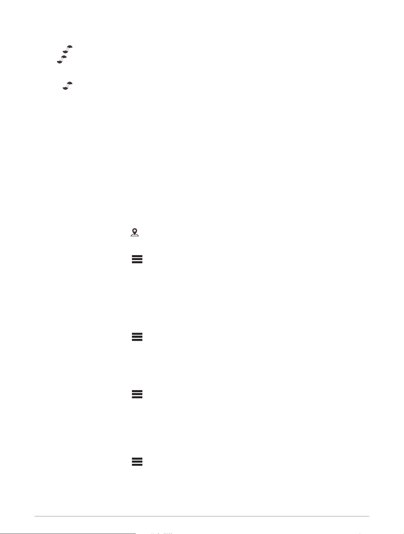
MOB Tag
The Man Overboard (MOB) tag is an included accessory intended to help ensure your safety when you leave the
kayak. When the MOB tag is turned on and paired to the trolling motor, the propeller automatically stops when
the MOB tag is submerged.
WARNING
You must wear the MOB tag on your body and make sure it is turned on and paired with the trolling motor for
the MOB automatic motor cut-off feature to work as expected. If the MOB tag is not powered on, paired and
attached to your body, or if the MOB tag is not submerged, the trolling motor does not automatically stop the
propeller. Leaving the kayak while the propeller is running may lead to serious personal injury or death.
Power and interface button:
• Press to check the status and battery level of the tag.
• Hold to turn the tag on or off.
MOB button:
• Hold to stop the propeller.
• After returning to the kayak, press to clear the MOB status and resume normal operation of the motor.
WARNING
You must make sure the area around the trolling motor is clear before resuming normal operation of
the motor. Resuming normal operation while others are near the trolling motor could result in serious
personal injury or death.
TIP: You can also clear the MOB status by pressing the MOB OVERRIDE on the trolling motor or by
dismissing the status message on the remote control or on a connected chartplotter.
When you press the power button, the LED color indicates the connection status of the tag:
• Green: connected.
• Red: not connected.
When you press the power button, the LED color indicates the battery status of the tag:
• Green: the battery level is high.
• Orange: the battery level is medium.
• Red: the battery level is low.
26 MOB Tag
Attaching the Band or Carabiner Loop
The MOB tag is packaged with a carabiner loop, a wristband, and a floating keytag. You can use the carabiner
loop to attach the MOB tag to your clothing, or you can attach the MOB tag to the wristband to wear it on your
wrist. You can also attach the floating keytag to the carabiner or to the wristband to prevent the MOB tag from
sinking if it is accidentally lost in the water. Follow these steps to attach the wristband or the carabiner loop to
the MOB tag.
1 Insert one end of the spring bar on the band or carabiner loop into one of the holes on the MOB tag.
2 Slide the quick-release pin to retract the other end of the spring pin.
3 Align the spring bar with the other hole in the MOB tag, and release the pin.
Overriding the MOB Tag
If the trolling motor loses its connection to the MOB tag, but you have not left the kayak, you can override the
MOB function to temporarily resume normal operation.
WARNING
You must make sure the area around the trolling motor is clear before resuming normal operation of the motor.
Resuming normal operation while others are near the trolling motor could result in serious personal injury or
death.
After the motor has lost its connection with the MOB tag, and the propeller has stopped, select an option:
• On the trolling motor remote, select > Settings > Trolling Motor > MOB Tag Override Mode.
• Hold the MOB OVERRIDE button on the top of the trolling motor housing for five seconds.
The trolling motor emits a long beep when you turn MOB Tag Override Mode on or off. The trolling motor beeps
periodically, and the status LED flashes yellow when MOB Tag Override Mode is on.
If you recover the MOB tag and its connection to the trolling motor is restored, the trolling motor automatically
turns off MOB Tag Override Mode. To resume normal operation, you must press the MOB button on the MOB
tag, or dismiss the MOB message on the remote control or a connected chartplotter.
MOB Tag 27

Pairing an MOB Tag with the Force Current Trolling Motor
The MOB tag included with the Force Current trolling motor is paired with the trolling motor at the factory.
Follow the steps to pair a new MOB tag with the trolling motor.
1 Make sure the trolling motor is turned on.
2 Hold the power button on the side of the MOB tag to turn it on.
The icon on the MOB tag flashes red.
3 On the trolling motor, press three times.
The LED indicator flashes blue as the motor searches for a connection.
4 Make sure the MOB tag is within 1m (3ft.) of the trolling motor.
5 Press the power button on the MOB tag three times quickly.
The icon on the MOB tag flashes blue as it searches for a connection.
When the connection is successful, the status LED on the trolling motor turns solid green.
28 MOB Tag
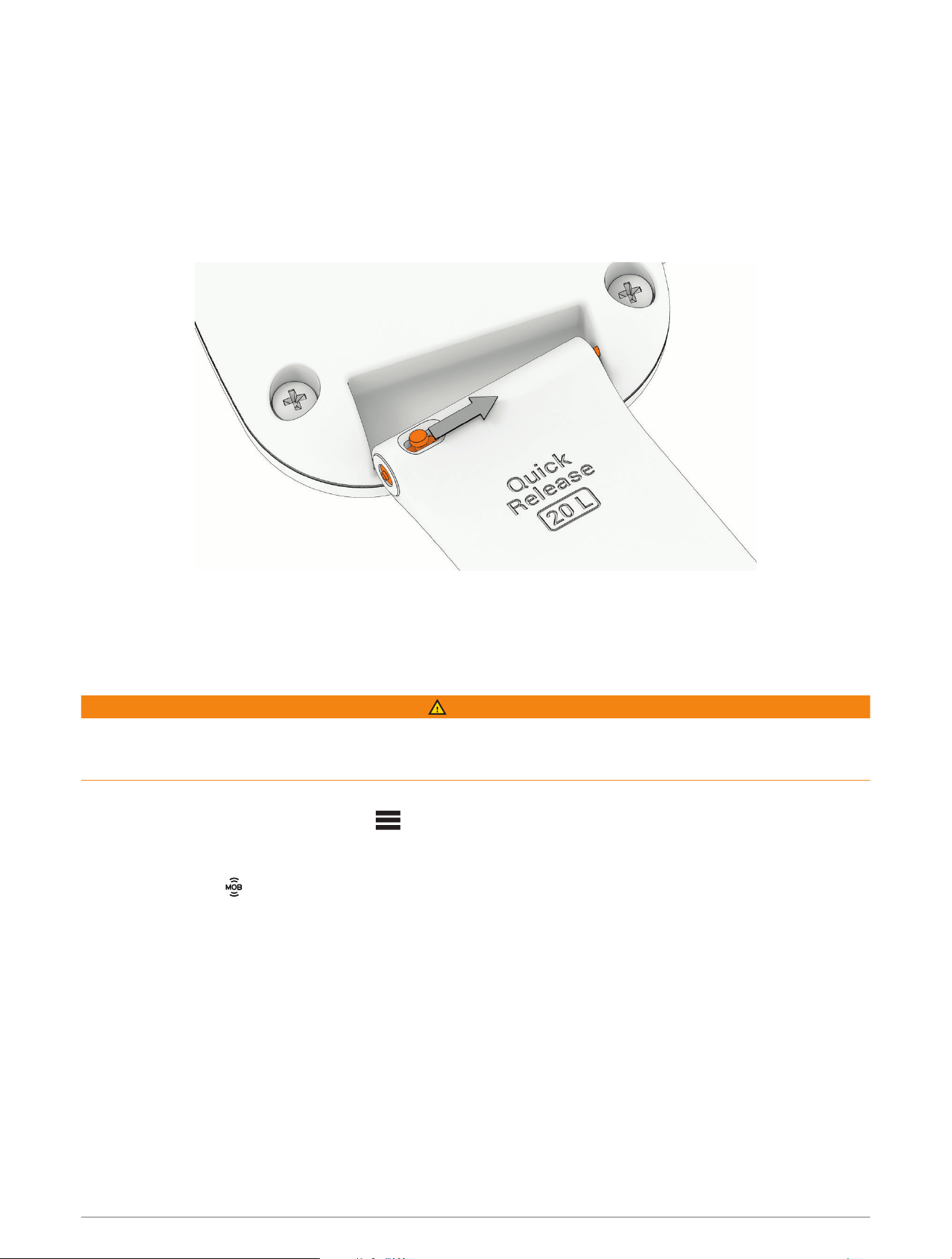
Replacing the MOB Tag Battery
WARNING
See the Important Safety and Product Information guide in the product box for product warnings and other
important information.
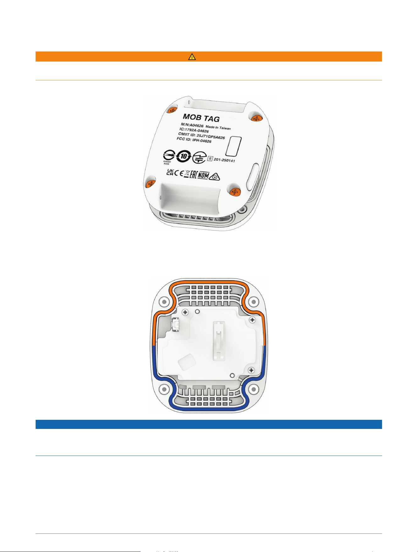
1 Using a #1 Phillips screwdriver, loosen the four captive screws to remove the back cover.
2 Gently lift the white tab to release the battery from the back cover.
3 Place the new battery in the back cover, with the positive (+) side down.
4 Make sure the rubber gasket in the front cover of the MOB tag is not broken and is fully seated in its groove.
The gasket fits in the groove in a specific orientation.
NOTICE
If the gasket is not properly and fully seated in the groove, it does not create a seal, which leads to the failure
of the MOB tag when it is exposed to water. See the Field Service Manual at garmin.com/manuals/force_current
_trolling_motor for information on purchasing a replacement gasket.
After you replace the battery, you may need to pair the MOB tag again (Pairing an MOB Tag with the Force
Current Trolling Motor, page28).
Power Steer Foot Pedals
The Power Steer Foot Pedals are an optional accessory included with some models.
Power Steer Foot Pedals 29
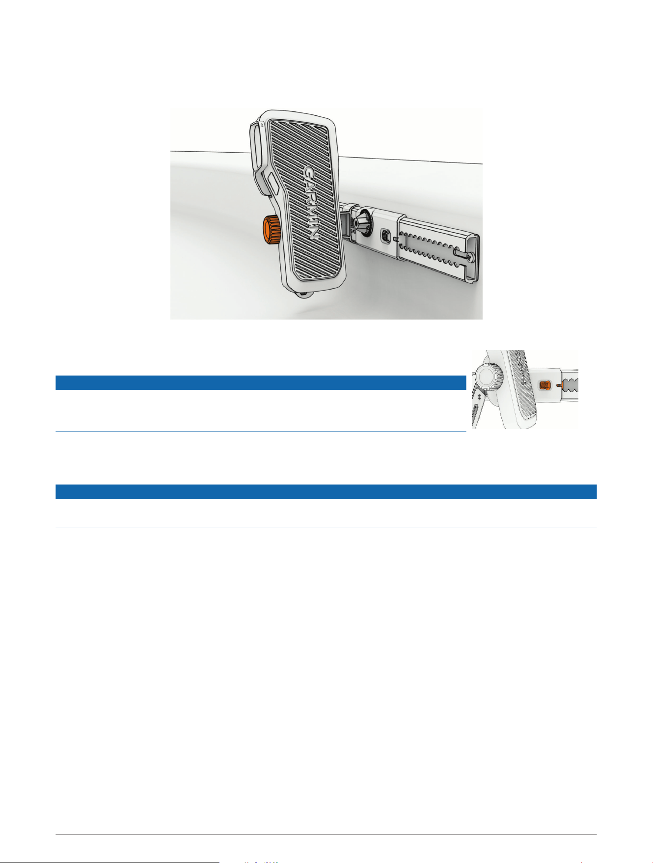
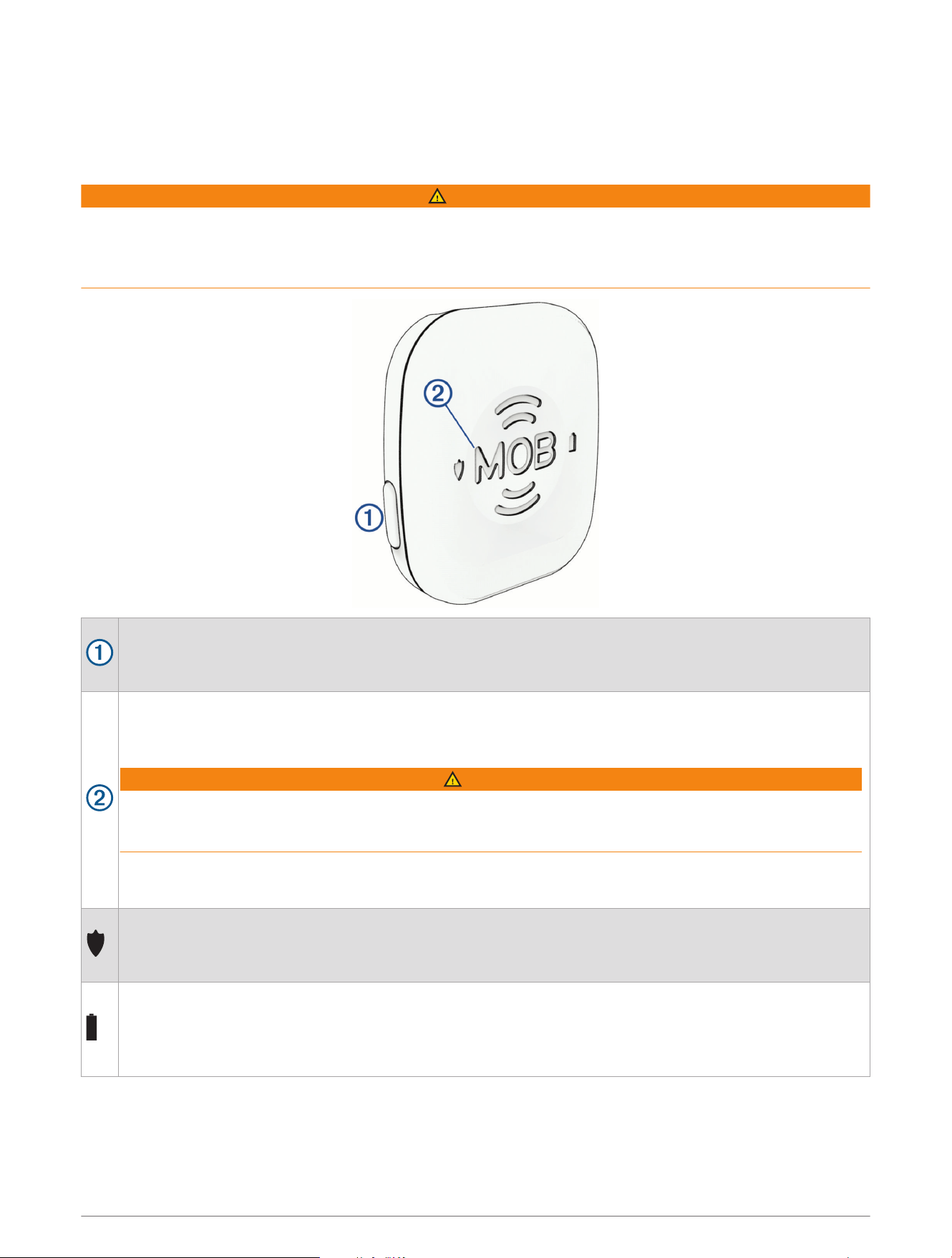
Attaching the Pedals to the Rails
1 Align the screw on the outside of the pedal with the threaded socket in the pedal carriage on the rail, and turn
the knob on the other side of the pedal, clockwise, to attach the pedal to the pedal carriage.
2 Tilt the pedal back and forth to check its range of motion, and adjust the angle of the pedal if necessary.
3 If necessary, push the button on the pedal carriage and slide it along the rail to
position the pedal at a comfortable distance.
NOTICE
Do not move the pedal carriages all the way to either end of the pedal rail. If the
pedal carriage overlaps one of the pedal rail mounting screws, it may become
difficult to move it.
4 Repeat the steps for the other pedal.
TIP: You can check the marks where the pedals connect to the pedal carriages to make sure both pedals are
installed at the same angle.
NOTICE
You must remove the pedals from the pedal carriages before transporting the kayak. The pedals may become
loose during transport, which could cause property damage.
30 Power Steer Foot Pedals
Steering with the Foot Pedals
WARNING
Learn to operate the foot pedals on calm and hazard-free open water. Start with small movements until you get
comfortable with the pedal response.
You can tilt each pedal forward or back from a neutral position. As you tilt the pedals further in either direction,
the propeller spins faster. The combined position of both pedals determines the angle of the propeller drive
motor.
• To move forward, tilt both pedals forward.
• To move backward, tilt both pedals back.
WARNING
When using the trolling motor to drive your kayak backward, the kayak may steer unexpectedly, due to the hull
interfering with the motor thrust. You must stay alert and aware of your surroundings when using the motor
to move your kayak backward, to avoid possible personal injury or product damage caused by an accidental
collision.
• To turn left, tilt the right-side pedal forward while keeping the left-side pedal in the neutral position.
The nose of the propeller drive motor turns to the right, turning the kayak to the left.
• To turn right, tilt the left-side pedal forward while keeping the right-side
pedal in the neutral position.
The nose of the propeller drive motor turns to the left, turning the kayak
to the right.
• To turn your kayak at a sharper angle, tilt one pedal forward while you
tilt the other pedal back.
The nose of the propeller drive motor turns to up to 90 degrees,
depending on the relative angle of each pedal.
NOTE: At steering angles greater than 45 degrees, the propeller drive
speed is automatically limited to reduce turbulence.
You can invert the right and left pedal response to emulate steering with a cable-controlled rudder instead
(Inverting the Steering Response, page32).
Power Steer Foot Pedals 31
Inverting the Steering Response
By default, the Power Steer foot pedals emulate differential steering, such as that of a zero-turn lawn mower.
You can invert the right and left pedal response to emulate steering with a cable-controlled rudder instead.
1 On the remote control, select > Settings > Trolling Motor > Steering Mode.
2 Select Rudder.
You can select Zero-Turn to revert to the default steering mode.
Using the Foot Pedal Levers
You can use the levers on each of the foot pedals to activate autopilot modes.
• To turn Heading Hold on or off, push the lever on the left pedal.
• To turn Anchor Lock on or off, push the lever on the right pedal.
Changing the Function of the Foot Pedal Levers
1 On the remote control, select > Settings > Trolling Motor > Programmable Keys.
2 Select an option:
• To configure the lever on the right pedal, select Right Pedal.
• To configure the lever on the left pedal, select Left Pedal.
3 Select an option:
• To disable the foot pedal lever, select None.
• To turn Anchor Lock on or off when you push the pedal lever, select Anchor Lock.
• To turn Heading Hold on or off when you push the pedal lever, select Heading Hold.
• To mark a waypoint at your present location when you push the pedal lever, select Mark Waypoint.
Pairing the Foot Pedals
If the foot pedals were included with the trolling motor, they are paired with the trolling motor at the factory.
Follow these steps to pair a new set of foot pedals.
You must pair each pedal separately.
1 Make sure the trolling motor is turned on.
2 On the trolling motor, press three times to enter pairing mode.
The LED indicator flashes blue as it searches for a connection.
3 Bring a foot pedal within 1m (3ft.) of the trolling motor.
4 Push the lever on the foot pedal three times.
The LED indicator light on the foot pedal flashes blue as it searches for a
connection, and turns solid green when the connection is successful.
5 Repeat steps 2 through 4 to pair the other foot pedal.
TIP: As a test, when pressing on the pedal lever, the LED indicator light flashes green
to indicate that the pedal is paired to the motor, or it flashes red to indicate that it is
not paired.
32 Power Steer Foot Pedals

Installing Batteries in the Foot Pedals
Each foot pedal operates using two AA batteries (not included). Use lithium batteries for the best results.
TIP: You can press the pedal lever two times to test the level. The LED indicator light on the pedal turns solid
green, yellow, or red to indicate the general battery level.
1 On a foot pedal, turn the D-ring counter-clockwise, and pull up to remove the cover.
2 Insert two AA batteries, observing polarity.
3 Replace the battery cover, and turn the D-ring clockwise.
4 Repeat these steps for the other pedal.
Status LED
The LED on each Power Steer foot pedal illuminates to indicate the status of the pedal.
Green The foot pedal is connected to the trolling motor, and a lever command was activated.
Blue The foot pedal is in pairing mode.
White The foot pedal is connected and was moved to the neutral position.
Purple
The foot pedal is installing a software update.
NOTICE
You must not remove power to the foot pedal when the software is updating, or it may damage the
pedal.
Red The foot pedal lever was activated, but the pedal is not connected to the trolling motor.
Connecting to a Mobile Device with the ActiveCaptain App
You can connect a mobile device to the trolling motor using the ActiveCaptain app. The app provides a quick
and easy way for you to interact with your trolling motor and update the device software.
1 On the remote control, select > Settings > Trolling Motor > Wi-Fi > Mode > ActiveCaptain > Setup.
2 Enter a name and password for this network.
3 From the application store on your mobile device, install and open the ActiveCaptain app.
4 Bring the mobile device near the trolling motor.
5 From your mobile device settings, open the Wi‑Fi connections page and connect to the trolling motor, using
the name and password you entered in the previous step.
Connecting to a Mobile Device with the ActiveCaptain App 33

Connecting to a Chartplotter
Your compatible Garmin chartplotter must have the latest software version installed before you can connect the
trolling motor.
You can connect the trolling motor wirelessly to a compatible Garmin chartplotter. After you connect to a
compatible chartplotter, you can control the trolling motor from the chartplotter.
1 Turn on the chartplotter and the trolling motor.
2 Make sure that the chartplotter is hosting a wireless network.
NOTE: If you have multiple chartplotters installed, only one is the wireless network host. Consult your
chartplotter's owner's manual for more information.
3 On the chartplotter, select Settings > Communications > Wireless Devices > Garmin Trolling Motor > Start.
4 On the trolling motor display panel, press three times to enter pairing mode.
The LED indicator light on the trolling motor illuminates blue as it searches for a connection to the
chartplotter, and changes to green when the connection is successful.
A confirmation message appears on the chartplotter when the connection is successful.
5 After the chartplotter and trolling motor connect successfully, enable the trolling motor bar on the
chartplotter to control the motor.
See the latest version of your chartplotter's owner's manual for complete operation instructions.
Connecting to a Garmin Watch
You can connect the trolling motor wirelessly to a compatible Garmin watch, and control the trolling motor using
the Trolling Motor app on the watch.
The first time you connect the trolling motor to your watch, you must pair the watch and the motor. After they
are paired, the watch connects to the motor automatically when the motor is powered on and within range.
1 Make sure the trolling motor is powered on and a remote control is connected to it.
2 Bring your compatible Garmin watch within 3m (10ft.) of the trolling motor.
3 On the watch, hold MENU.
4 Select Sensors & Accessories > Add New > Trolling Motor.
5 On the trolling motor display panel, press three times to enter pairing mode.
on the trolling motor display panel is solid blue as it searches for a connection, and changes to solid green
when the connection is successful.
6 Confirm the pairing code shown on the watch and on the connected remote control.
You can press START and select Trolling Motor from the list of activities and apps to open the trolling motor
controls.
Software Updates
You can go to garmin.com/support/software/marine/ to find information on the latest software updates for
your Garmin marine devices.
34 Connecting to a Chartplotter

Maintenance Needs and Schedule
NOTICE
After using the motor in salt water or brackish water, you should rinse off the entire motor with fresh water, and
apply a water-based silicone spray using a soft cloth. You must avoid spraying jets of water at the motor, to
prevent water ingress that could lead to product damage.
To maintain your warranty, you must perform routine maintenance tasks to prepare your motor for the season.
For the Force Current trolling motor:
• Check the end of the pull rope under the mount latch, and tie a new stopper knot if necessary.
• Check the movement of the mount latch. If it does not spring back smoothly, clean and lubricate the mount
latch.
• Check the end of the pull rope in the pull handle, and tie a new stopper knot if necessary.
• Check the rope pulleys in the motor mount and in the cleat and make sure they rotate freely. Clean or replace
any damaged part if necessary.
• Check the pull handle, and replace it if there are cracks or other signs of wear.
• Check the entire length of the pull rope for fraying or other signs of wear. Replace it if necessary.
• Check the pad eyes and the cleat. Tighten the mounting screws if necessary. Replace the pad eyes and the
cleat If there are cracks or other signs of wear on them.
• Check the screws securing the mount to the kayak. Tighten or replace them if necessary.
• Check the mounting surface around the mount. If there are signs of wear, consider reinforcing the mounting
surface and reinstalling the mount.
• Check the motor mount, and replace it if there are cracks or other signs of damage.
• Check the motor pivot knobs, and replace them if there are cracks or other signs of damage.
• Check the entire length of the power cable for wear, and replace it if necessary.
• Check the power cable connector for corrosion or bent sockets. Clean or replace the cable if necessary.
• Check the power connector cover on the motor to make sure it fits correctly to protect the power connector.
Replace the connector cover if necessary.
• Check the anodes on the propeller drive motor, and replace them if necessary (Checking the Sacrificial
Anodes, page37).
• Check the propeller to make sure the propeller nut is tightened to 16.27 N-m (12 lbf-ft.).
• Check the propeller for wear. Replace it if necessary (Changing the Propeller, page10).
For the Power Steer foot pedals:
• Check the screws securing the pedal rails to the kayak. Tighten if necessary.
• Check the battery compartment in the foot pedals to make sure the batteries have not ruptured. Clean the
battery contacts if necessary.
You can order the most common replacement parts and accessories at garmin.com/accessories/force_current
_trolling_motor. For service instructions and information on other replacement parts, see the Field Service
Manual on garmin.com/manuals/force_current_trolling_motor .
Maintenance Needs and Schedule 35
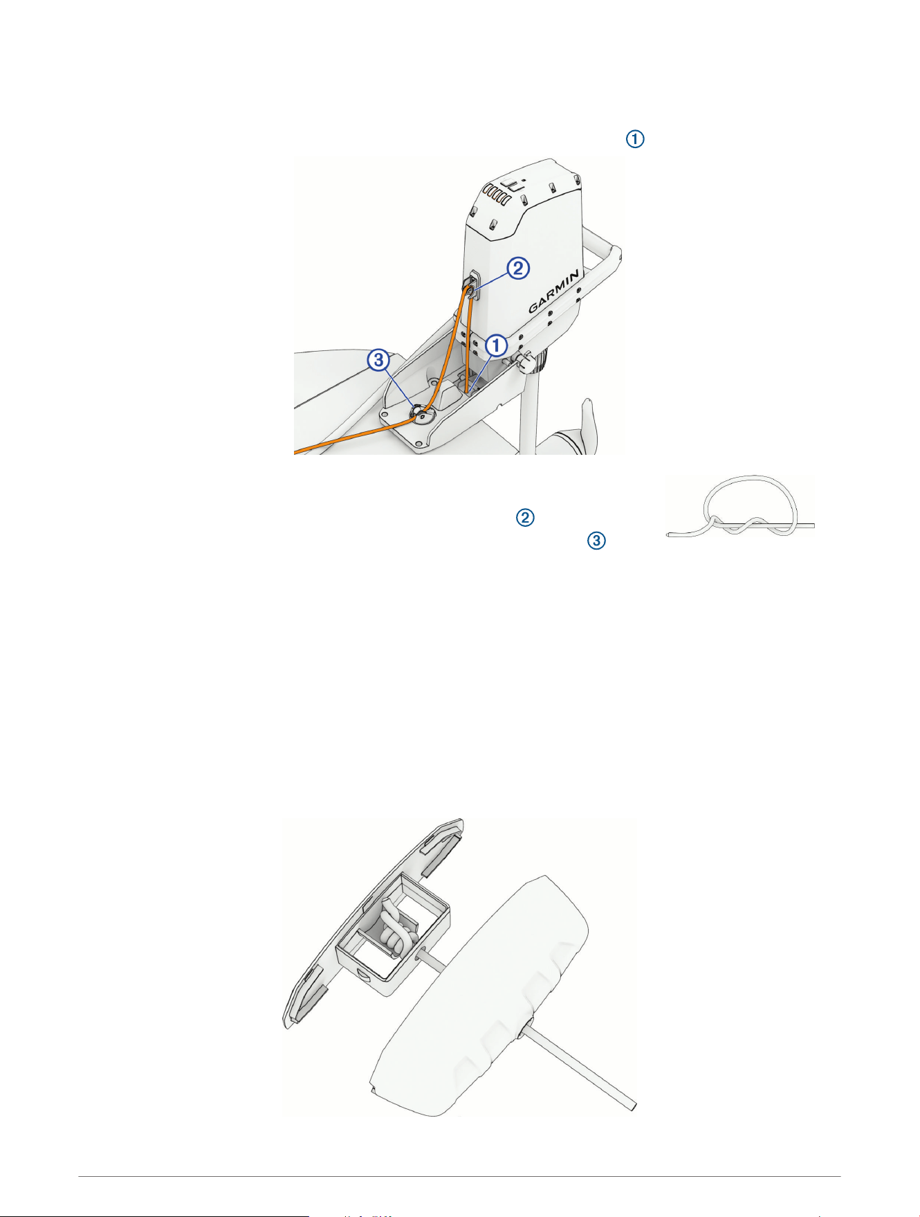
Replacing the Pull Rope
1 Cut the worn or damaged rope and remove it from the motor and from the rope handle.
2 Feed one end of the new rope through the metallic release latch in the mount .
3 Tie the end of the new rope under the mount into a stopper knot to prevent the
rope from pulling out through the release latch.
4 Feed the rope up through the eyelet on the front of the motor .
5 Guide the rope down and feed it through the swivel pulley on the mount .
6 Route the rope through the pad eyes and the cleat.
7 Install the rope handle on the new rope (Installing the Rope Handle, page36).
Installing the Rope Handle
1 Feed the end of the rope through the two pieces of the pull handle.
2 Trim the rope, allowing enough slack to make sure you can comfortably reach it from your position seated in
your kayak.
TIP: We recommend trimming the rope to about 20cm (8in.) from the cleat, so the pull handle will stay
close to the cleat when the motor is in the deployed position.
3 Tie a stopper knot to bind the rope inside the pull handle.
4 If necessary, trim and melt the end of the rope to prevent fraying.
5 Snap the two pieces of the pull handle together.
36 Maintenance Needs and Schedule
Checking the Sacrificial Anodes
1 Using a
9
/
16
in. (15mm) socket, loosen the nut on the end of the propeller.
2 Remove the propeller and set aside the nut, the lock washer, and the flat washer.
3 Remove and examine the propeller anode .
4 Using a 3mm hex key, remove and examine the propeller drive anode .
5 Select an option:
• If either anode is half of its original size or larger, clean it using a wire brush or sandpaper.
NOTICE
You should remove the anode from the motor before cleaning it with a wire brush or sandpaper. Cleaning the
anode while it is installed on the motor could damage the motor, accelerate corrosion, and shorten the life of
the motor.
• If the anode is smaller than half of its original size, discard the anode and purchase a replacement.
You can purchase a set of replacement anodes at garmin.com/accessories/force_current_trolling_motor.
NOTICE
When reinstalling the propeller on the propeller drive motor, you must tighten the propeller nut to 16.27N-m
(12lbf-ft.) to secure it properly.
Maintenance Needs and Schedule 37

Specifications
Trolling Motor
Weight
Motor only: 10.1kg (22.2lbs)
With mount and cable: 12.6kg (27.8lbs)
Operating temperature From -5° to 40°C (from 32° to 104°F)
Storage temperature From -40° to 85°C (-40° to 185°F)
Water rating
Steering system housing: IEC 60529 IPX7
6
Propeller drive motor housing: IEC 60529 IPX8
7
Compass safe distance 91cm (3ft.)
Power cable length 165cm (5ft.5 in.)
Input voltage From 12 to 24Vdc
Input amperage 40A continuous
Breaker (not included)
32VDC or greater, suitable for 40A continuous
NOTE: You can protect the system by using a larger circuit breaker, not to
exceed 60A, if you are operating under high temperatures or if you are sharing
the circuit with other devices. You should verify that your boat wiring meets
marine wiring standards using a larger breaker before changing it.
Maximum power consump
tion
420W @ 12Vdc
768W @ 24Vdc
Wireless frequency and
transmit power
2.4GHz @ 19.0dBm maximum
6
Withstands incidental exposure to water of up to 1 meter for up to 30 minutes.
7
Withstands continuous immersion in water up to 3meters deep.
38 Specifications
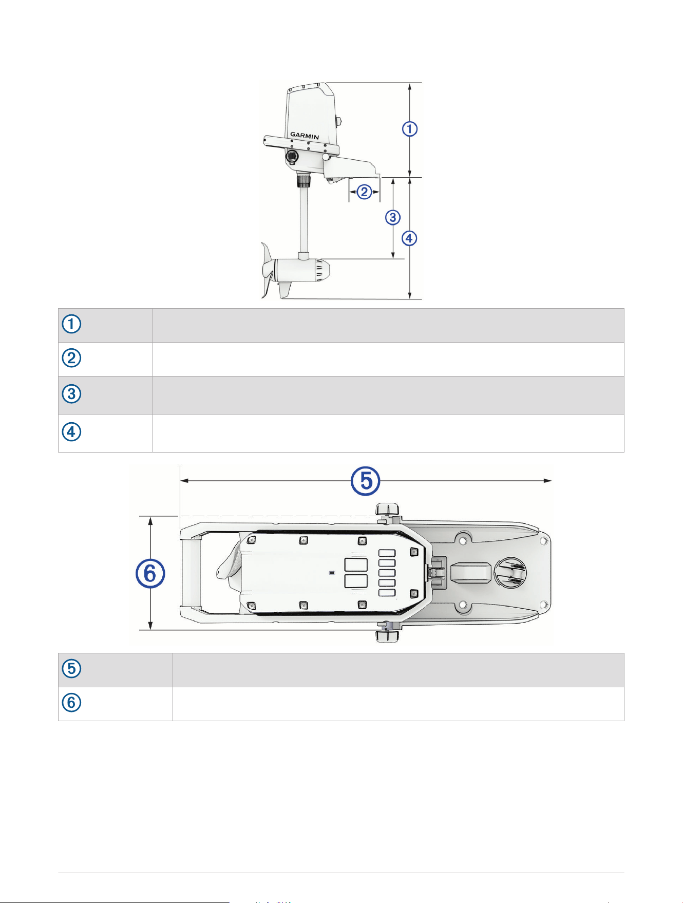
Dimensions
431 mm (17in.)
29mm (1
1
/
8
in.)
290mm (11
3
/
8
in.) min.
422mm (16
5
/
8
in.) max.
470mm (18
1
/
2
in.) min.
602mm (23
3
/
4
in.) max.
527mm (20
3
/
4
in.)
185mm (7
5
/
16
in.)
Specifications 39
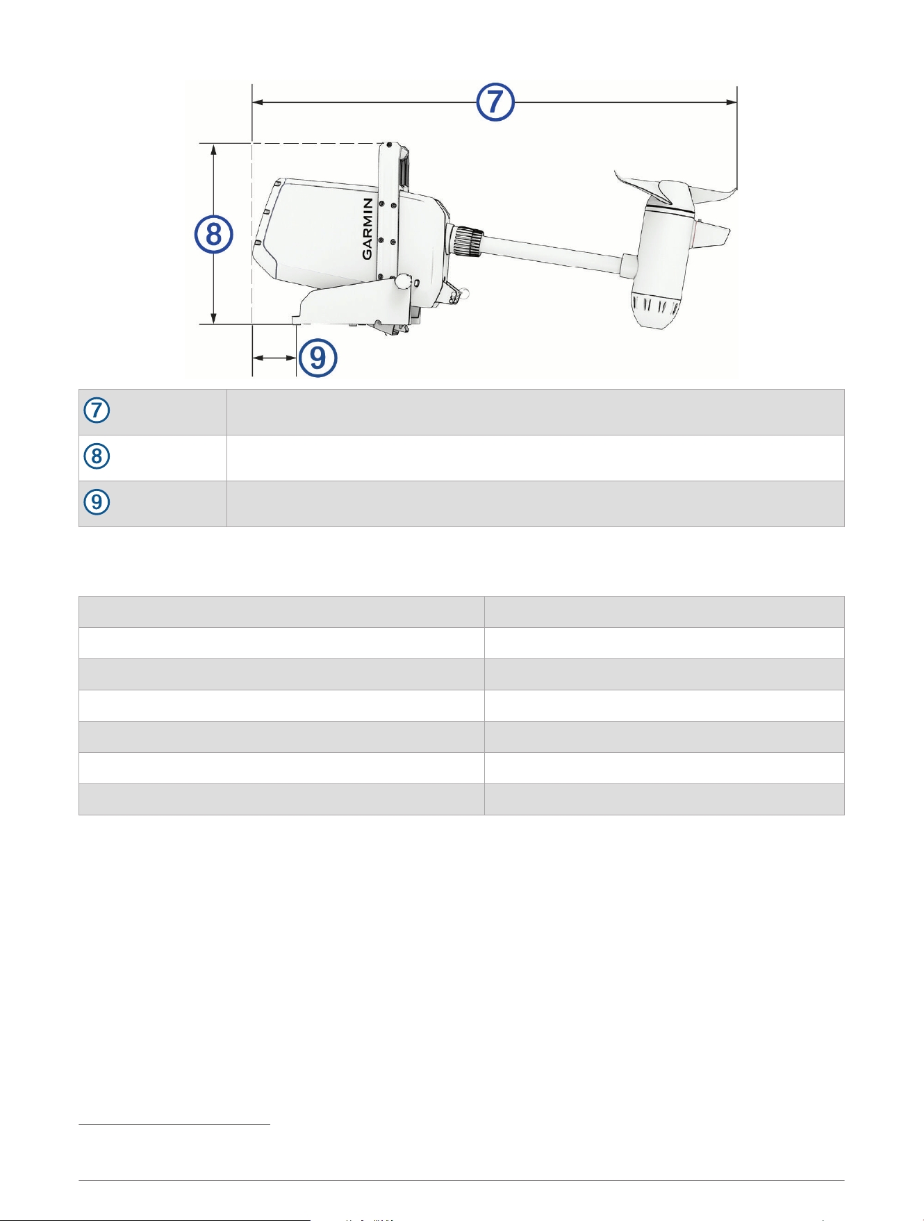
1005mm (39
5
/
8
in.)
385mm (15
3
/
16
in.)
112mm (4
3
/
8
in.)
Power Steer Foot Pedals
The Power Steer foot pedals are only included with some models.
Weight (complete system, including rails) 3.08kg (6.8lb.)
Operating temperature From -5° to 40°C (from 32° to 104°F)
Storage temperature From -40° to 85°C (-40° to 185°F)
Water rating IEC 60529 IPX7
8
Compass safe distance 61cm (24in.)
Power Supply 2 AA batteries per pedal
Wireless frequency and transmit power 2.4GHz @ 9.1dBm maximum
8
Withstands incidental exposure to water of up to 1 meter for up to 30 minutes.
40 Specifications
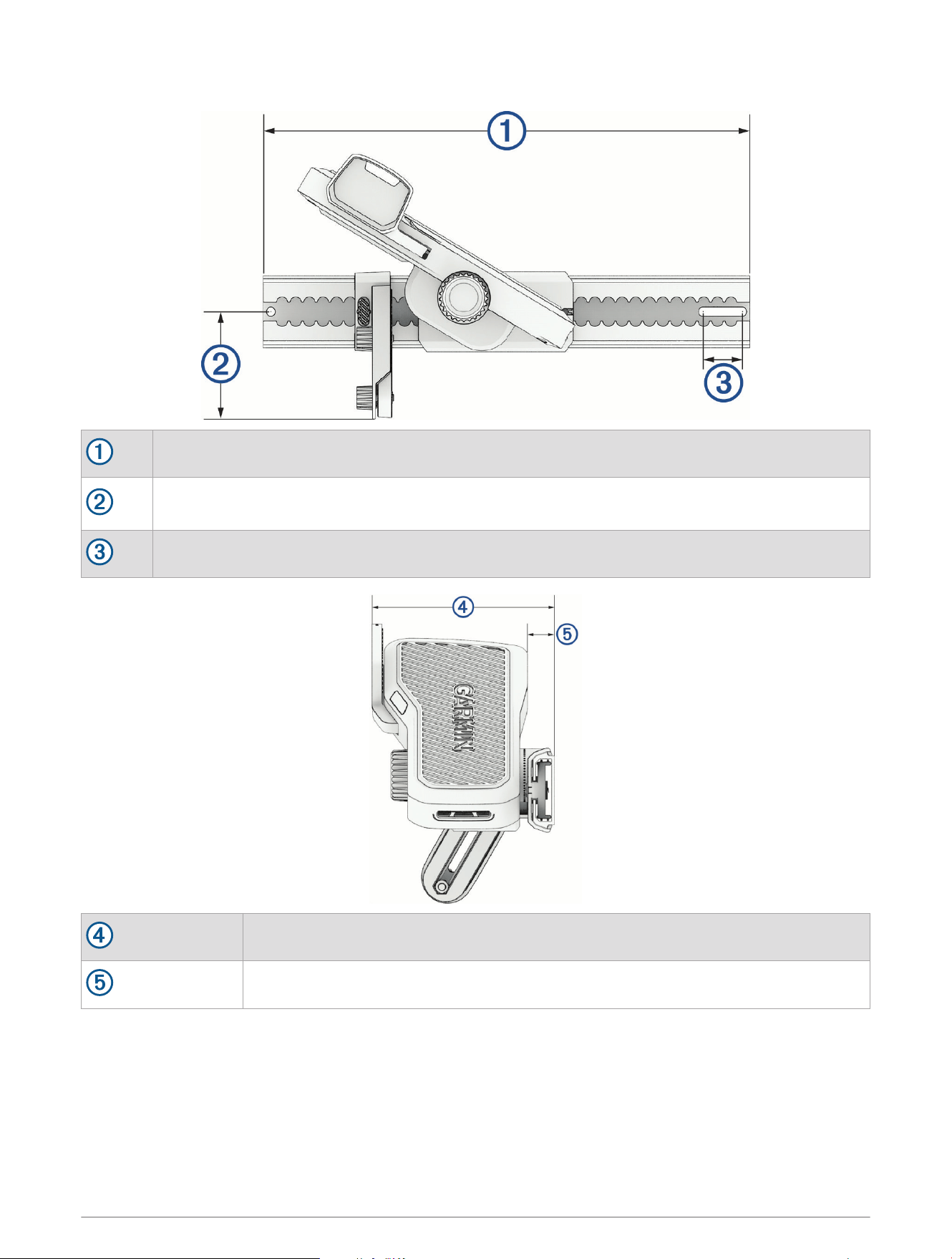
Dimensions
394mm (15
1
/
2
in.)
87mm (3
7
/
16
in.) minimum (short stabilizer arm)
196mm (7
11
/
16
in.) maximum (long stabilizer arm)
32mm (1
1
/
4
in.)
141mm (5
9
/
16
in.)
21mm (
13
/
16
in.)
Specifications 41

Remote Control
Dimensions (W×H×D) 152 x 52 x 32mm (6 x 2 x 1
1
/
4
in.)
Weight 109g (3.8oz.) without batteries
Material Glass-filled nylon
Display type Sunlight-visible, transflective memory-in-pixel (MIP)
Display resolution R240 x 240 pixels
Display size (diameter) 30.2mm (1
3
/
16
in.)
Operating temperature From -15° to 55°C (5° to 131°F)
Storage temperature From -40° to 85°C (-40° to 185°F)
Battery type 2 AA (not included)
Battery life 240 hr., typical use
Radio frequency 2.4GHz @ 10.0dBm nominal
Water rating IEC 60529 IPX7
9
Compass-safe distance 15cm (6in.)
MOB Tag
Weight
21.635g (black model)
21.222g (white model)
Battery type CR2032 lithium coin cell
Operating temperature From−15° to 60°C (from 5° to 140°F)
Compass-safe distance 5cm (1.97in.)
Water rating IEC 60529 IPX8 (5ATM)
10
Wireless frequency and transmit power 2.4GHz @ +8dBm nominal
9
Withstands incidental exposure of water up to 1m for up to 30min.
10
Withstands incidental exposure to water up to 50m for up to 30min. For more information, go to garmin.com/waterrating


support.garmin.com
GUID-91136105-7EB2-442E-8C25-7B4CF00FC466 v1July 2025