

Visit our website at: http://www.harborfreight.com
Email our technical support at: [email protected]
Owner’s Manual & Safety Instructions
Save This Manual Keep this manual for the safety warnings and precautions, assembly,
operating, inspection, maintenance and cleaning procedures. Write the product’s serial number in the
back of the manual near the assembly diagram (or month and year of purchase if product has no number).
Keep this manual and the receipt in a safe and dry place for future reference.
When unpacking, make sure that the product is intact
and undamaged. If any parts are missing or broken,
please call 1-<?>-1-888-380-0318 as soon as possible.
Copyright
©
2017 by Harbor Freight Tools
®
. All rights reserved.
No portion of this manual or any artwork contained herein may be reproduced in
any shape or form without the express written consent of Harbor Freight Tools.
Diagrams within this manual may not be drawn proportionally. Due to continuing
improvements, actual product may differ slightly from the product described herein.
Tools required for assembly an d se rv ic e may n ot b e in cl uded.
Read this material before using this product.
Failure to do so can result in serious injury.
SAVE THIS MANUAL.
Owner’s Manual & Safety Instructions
Save This Manual Keep this manual for the safety warnings and precautions, assembly,
operating, inspection, maintenance and cleaning procedures. Write the product’s serial number in the
back of the manual near the assembly diagram (or month and year of purchase if product has no number).
Keep this manual and the receipt in a safe and dry place for future reference.
When unpacking, make sure that the product is intact
and undamaged. If any parts are missing or broken,
please call 1-888-380-0318 as soon as possible.
Copyright
©
2017 by Harbor Freight Tools
®
. All rights reserved.
No portion of this manual or any artwork contained herein may be reproduced in
any shape or form without the express written consent of Harbor Freight Tools.
Diagrams within this manual may not be drawn proportionally. Due to continuing
improvements, actual product may differ slightly from the product described herein.
Too ls r eq ui re d for a ss em bl y and s er vi ce m ay not be i nc lu de d.
Read this material before using this product.
Failure to do so can result in serious injury.
SAVE THIS MANUAL.
Owner’s Manual & Safety Instructions
Save This Manual Keep this manual for the safety warnings and precautions, assembly,
operating, inspection, maintenance and cleaning procedures. Write the product’s serial number in the
back of the manual near the assembly diagram (or month and year of purchase if product has no number).
Keep this manual and the receipt in a safe and dry place for future reference. 17e
When unpacking, make sure that the product is intact
and undamaged. If any parts are missing or broken,
please call 1-888-380-0318 as soon as possible.
Copyright
©
2017 by Harbor Freight Tools
®
. All rights reserved.
No portion of this manual or any artwork contained herein may be reproduced in
any shape or form without the express written consent of Harbor Freight Tools.
Diagrams within this manual may not be drawn proportionally. Due to continuing
improvements, actual product may differ slightly from the product described herein.
Too ls r eq ui re d for a ss em bl y and s er vi ce m ay not be i nc lu de d.
Read this material before using this product.
Failure to do so can result in serious injury.
SAVE THIS MANUAL.
Page 2 For technical questions, please call 1-888-380-0318. Item 63793
SAFETy MAINTENANcEBASIc WELdINg WELdINg TIpSSETUPSAFETy MAINTENANcEBASIc WELdINg WELdINg TIpSSETUP
Table of contents
Safety ......................................................... 2
Specifications ............................................. 5
Setup .......................................................... 6
Maintenance and Service .......................... 17
Parts List and Diagram .............................. 19
Warranty .................................................... 20
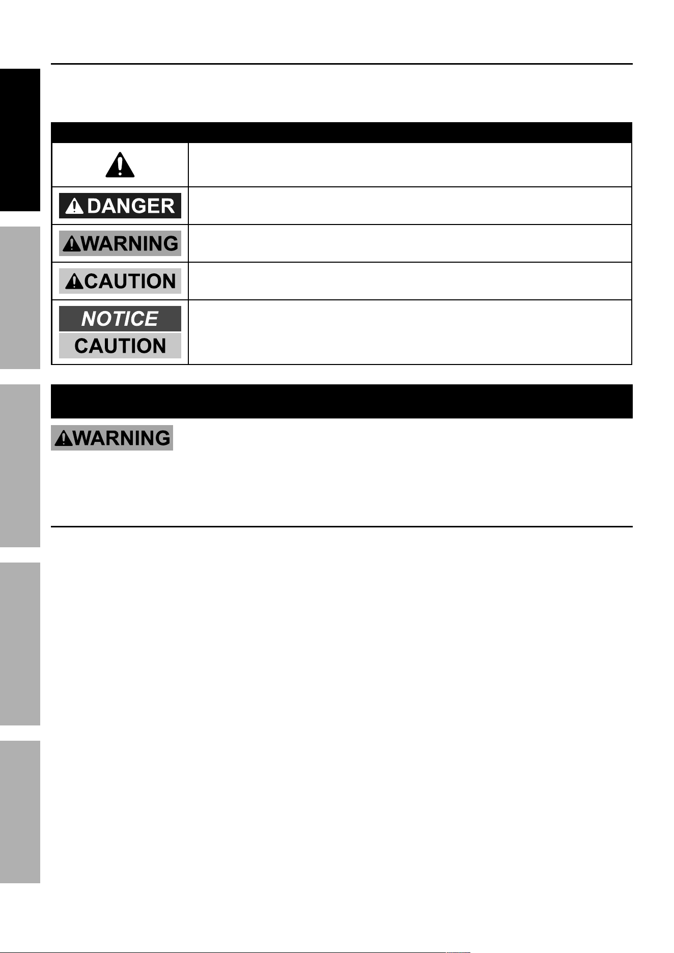
WARNINg SyMBOLS ANd dEFINITIONS
This is the Safety alert symbol. It is used to alert you to potential
personal injury hazards. Obey all Safety messages that
follow this symbol to avoid possible injury or death.
Indicates a hazardous situation which, if not avoided,
will result in death or serious injury.
Indicates a hazardous situation which, if not avoided,
could result in death or serious injury.
Indicates a hazardous situation which, if not avoided,
could result in minor or moderate injury.
Addresses practices not related to personal injury.
IMpORTANT SAFETy INFORMATION
Read all Safety warnings and instructions.
Failure to follow the warnings and instructions may result in electric shock, fire and/or serious injury.
Save all warnings and instructions for future reference.
general Safety
pROTEcT yourself and others. Read and understand this information.
1. Before use, read and understand
manufacturer′s instructions,
Material Safety Data Sheets (MSDS′s),
employer′s Safety practices, and ANSI Z49.1.
2. Keep out of reach of children.
Keep children and bystanders away while operating.
3. place the welder on a stable location before use.
If it falls while plugged in, severe injury,
electric shock, or fire may result.
4. do not overreach.
Keep proper footing and balance at all times.
5. Stay alert, watch what you are doing and use
common sense when operating a welder.
do not use a welder while you are tired or under
the influence of drugs, alcohol or medication.
A moment of inattention while operating welders
may result in serious personal injury.
6. Avoid unintentional starting. Make sure you are
prepared to begin work before turning on the Welder.
7. Never leave the Welder unattended while
energized. Turn power off if you have to leave.
8. The warnings, precautions, and instructions
discussed in this instruction manual cannot
cover all possible conditions and situations
that may occur. It must be understood by the
operator that common sense and caution are
factors which cannot be built into this product,
but must be supplied by the operator.
Page 3For technical questions, please call 1-888-380-0318.Item 63793
SAFETyMAINTENANcE BASIc WELdINgWELdINg TIpS SETUP SAFETyMAINTENANcE BASIc WELdINgWELdINg TIpS SETUP
Fume and gas Safety
INHALATION HAZARD:
Welding and plasma cutting produce toxic fumes.
1. Exposure to welding or cutting exhaust
fumes can increase the risk of developing
certain cancers, such as cancer of the
larynx and lung cancer. Also, some diseases
that may be linked to exposure to welding
or plasma cutting exhaust fumes are:
• Early onset of Parkinson’s Disease
• Heart disease
• Ulcers
• Damage to the reproductive organs
• Inflammation of the small intestine or stomach
• Kidney damage
• Respiratory diseases such as
emphysema, bronchitis, or pneumonia
Use natural or forced air ventilation and wear
a respirator approved by NIOSH to protect
against the fumes produced to reduce the
risk of developing the above illnesses.
2. do not use near degreasing or
painting operations.
3. Keep head out of fumes.
Do not breathe exhaust fumes.
4. Use enough ventilation, exhaust at arc, or
both, to keep fumes and gases from breathing
zone and general area. If engineering controls
are not feasible, use an approved respirator.
5. Work in a confined area only if it
is well-ventilated, or while wearing
an air-supplied respirator.
6. Have a recognized specialist in
Industrial Hygiene or Environmental Services
check the operation and air quality
and make recommendations
for the specific welding situation.
Follow OSHA guidelines for
Permissible Exposure Limits (PEL’s) and
the American Conference of Governmental
Industrial Hygienists recommendations for
Threshold Limit Values (TLV’s) for fumes and gases.
Arc Ray Safety
ARc RAyS can injure eyes and burn skin.
1. Wear ANSI-approved welding eye protection
featuring at least a number 10 shade lens rating.
2. Wear leather leggings, fire resistant shoes
or boots during use. Do not wear pants with
cuffs, shirts with open pockets, or any clothing
that can catch and hold molten metal or sparks.
3. Keep clothing free of grease, oil,
solvents, or any flammable substances.
Wear dry, insulating gloves and protective clothing.
4. Wear an approved head covering to protect
the head and neck. Use aprons, cape, sleeves,
shoulder covers, and bibs designed and
approved for welding and cutting procedures.
5. Wear an approved welding jacket or long sleeves
to protect forearms from radiation burns.
6. When welding/cutting overhead or in confined
spaces, wear flame resistant ear plugs or
ear muffs to keep sparks out of ears.
Electrical Safety
ELEcTRIc SHOcK can KILL.
1. Turn off, disconnect power, and
discharge Electrode to ground before setting
down torch/Electrode holder and before service.
2. do not touch energized electrical parts.
Wear dry, insulating gloves. Do not touch Electrode
holder, Electrode, welding torch, or welding wire with
bare hand. Do not wear wet or damaged gloves.
3. connect to grounded, gFcI-protected
power supply only.
4. do not use near water or damp objects.
5. people with pacemakers should consult their
physician(s) before use. Electromagnetic fields
in close proximity to heart pacemaker could cause
pacemaker interference or pacemaker failure.
6. do not expose welders to rain or wet conditions.
Water entering a welder will increase
the risk of electric shock.
7. do not abuse the cord. Never use the cord
for carrying, pulling or unplugging the welder.
Keep cord away from heat, oil, sharp edges
or moving parts. Damaged or entangled
cords increase the risk of electric shock.
8. do not use outdoors.
9. Insulate yourself from the workpiece and
ground. Use nonflammable, dry insulating
material if possible, or use dry rubber mats,
dry wood or plywood, or other dry insulating
material large enough to cover your full
area of contact with the work or ground.

Page 4 For technical questions, please call 1-888-380-0318. Item 63793
SAFETy MAINTENANcEBASIc WELdINg WELdINg TIpSSETUPSAFETy MAINTENANcEBASIc WELdINg WELdINg TIpSSETUP
Fire Safety
ARc ANd SLAg can cause fire.
1. clear away or protect flammable objects.
Remove or make safe all combustible materials for a
radius of 35 feet (10 meters) around the work area.
Use a fire resistant material to cover
or block all open doorways, windows,
cracks, and other openings.
2. Keep ABc-type fire extinguisher near
work area and know how to use it.
3. Maintain a safe working environment.
Keep the work area well lit.
Make sure there is adequate
surrounding workspace. Keep the work area free
of obstructions, grease, oil, trash, and other debris.
4. do not operate welders in atmospheres
containing dangerously reactive or
flammable liquids, gases, vapors, or dust.
Provide adequate ventilation in work areas
to prevent accumulation of such substances.
Welders create sparks which may ignite flammable
substances or make reactive fumes toxic.
5. If working on a metal wall, ceiling, etc.,
prevent ignition of combustibles on the
other side by moving the combustibles to a
safe location. If relocation of combustibles is
not possible, designate someone to serve as
a fire watch, equipped with a fire extinguisher,
during the cutting process and for at least one
half hour after the cutting is completed.
6. do not weld or cut on materials having
a combustible coating or combustible
internal structure, as in walls or ceilings, without
an approved method for eliminating the hazard.
7. do not dispose of hot slag in containers
holding combustible materials.
8. After welding, make a thorough examination
for evidence of fire. Be aware that easily
visible smoke or flame may not be present
for some time after the fire has started.
9. do not apply heat to a container that has held
an unknown substance or a combustible
material whose contents, when heated,
can produce flammable or explosive vapors.
Clean and purge containers before applying heat.
Vent closed containers, including castings,
before preheating, welding, or cutting.
Welder Use and care
1. do not use the welder if the switch does not turn
it on and off. Any welder that cannot be controlled
with the switch is dangerous and must be repaired.
2. disconnect the plug from the power
source before making any adjustments,
changing accessories, or storing welders.
Such preventive Safety measures reduce the
risk of starting the welder accidentally.
3. prevent unintentional starting.
Ensure the switch is in the off-
position before connecting to power
source or moving the welder. Carrying
or energizing welders that have the
switch on invites accidents.
4. Store idle welders out of the reach of
children and do not allow persons unfamiliar
with the welder or these instructions to
operate the welder. Welders are dangerous
in the hands of untrained users.
5. Use the welder and accessories in
accordance with these instructions, taking
into account the working conditions and
the work to be performed. Use of the welder
for operations different from those intended
could result in a hazardous situation.
6. do not use the welder for pipe thawing.
Maintenance
1. Maintain welders. check for misalignment or
binding of moving parts, breakage of parts
and any other condition that may affect the
welder’s operation. If damaged, have the
welder repaired before use. Many accidents
are caused by poorly maintained welders.
2. Have your welder serviced by a qualified
repair person using only identical
replacement parts. This will ensure that
the Safety of the welder is maintained.
Page 5For technical questions, please call 1-888-380-0318.Item 63793
SAFETyMAINTENANcE BASIc WELdINgWELdINg TIpS SETUP SAFETyMAINTENANcE BASIc WELdINgWELdINg TIpS SETUP
3. Maintain labels and nameplates on the Welder.
These carry important information.
If unreadable or missing, contact
Harbor Freight Tools for a replacement.
4. Unplug before maintenance. Unplug the Welder
from its electrical outlet before any inspection,
maintenance, or cleaning procedures.
gas Shielded Welding - cylinder Safety
cylinders can explode when damaged.
1. do not weld on a pressurized or closed cylinder.
2. do not allow an Electrode holder,
Electrode, welding torch, or welding
wire to touch the cylinder.
3. Keep cylinders away from any electrical circuits,
including welding circuits.
4. Keep protective cap in place over the valve
except when the cylinder is in use.
5. Use only correct gas shielding equipment
designed specifically for the type of welding
you will do. Maintain this equipment properly.
6. protect gas cylinders from heat, being struck,
physical damage, slag, flames, sparks, and arcs.
7. Use proper procedures to move cylinders.
SAVE THESE INSTRUcTIONS.
Wire Feed (Speed)
Workpiece Ground Cable
Torch Cable
Overheat Shutdown Indicator
Cooling Fan
VAc
Volts Alternating Current
A
Amperes
OcV
Open Circuit Voltage
IpM
Inches Per Minute
AWg
American Wire Gauge
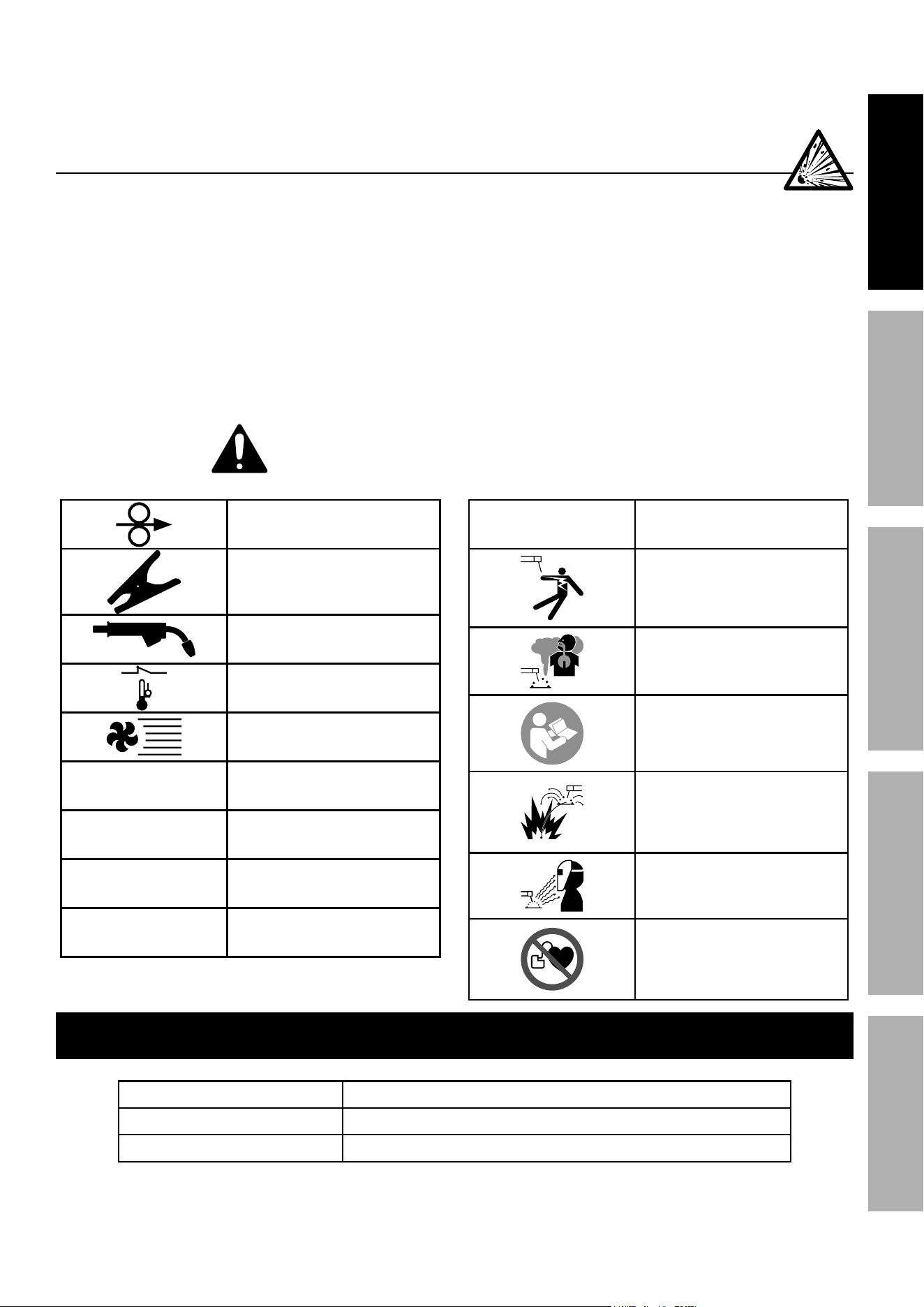
Electric Shock Hazard.
Do not touch energized parts.
Inhalation Hazard.
Keep head out of fumes
and use proper ventilation.
Read manual before
setup and/or use.
Fire Hazard.
Keep flammable materials
away during welding. Spatter
can cause accidental fires.
Arc Ray Hazard.
Wear welding helmet with
properly rated filter lens.
Pacemaker Hazard.
Welding processes may
interfere with pacemakers.
Consult doctor before use.
Specifications
Wire Types Aluminum and Steel alloys
Wire Capacity 4" Spool, - 1lb aluminum and 2lb steel, 0.030" / 0.035"diameter
Rated Duty Cycle 35% @ 160 A
Page 6 For technical questions, please call 1-888-380-0318. Item 63793
SAFETy MAINTENANcEBASIc WELdINg WELdINg TIpSSETUP
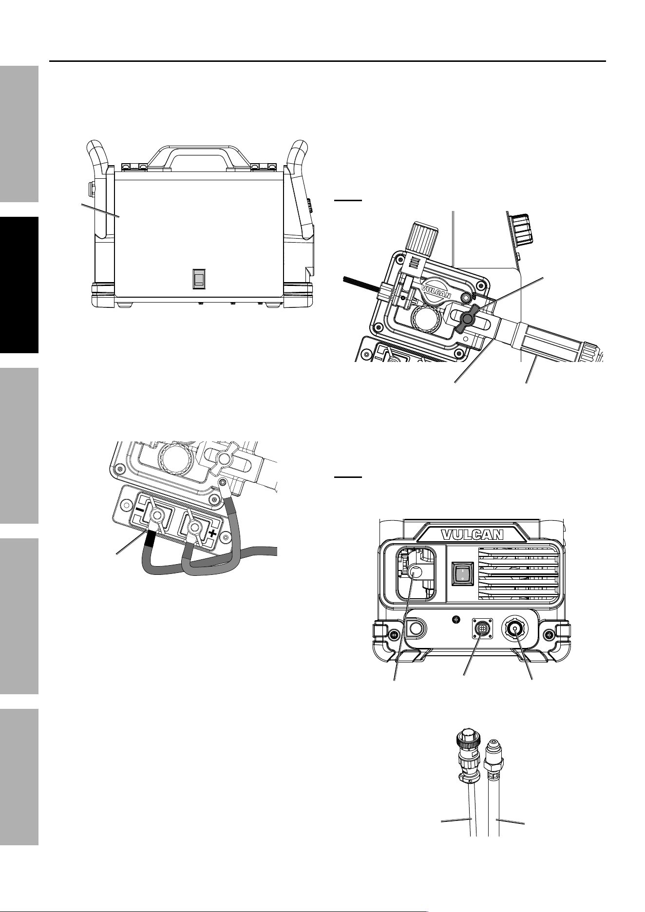
Setup
Read the ENTIRE IMpORTANT SAFETy INFORMATION section at the beginning of this
manual including all text under subheadings therein before set up or use of this product.
TO pREVENT SERIOUS INJURy FROM AccIdENTAL OpERATION:
Turn the power Switch off and unplug the welder before set up.
Place the Welder on a level surface that can bear its weight near the work
area. Leave space around the Welder for proper air flow.
Note: The following instructions are for welding with Aluminum wire.
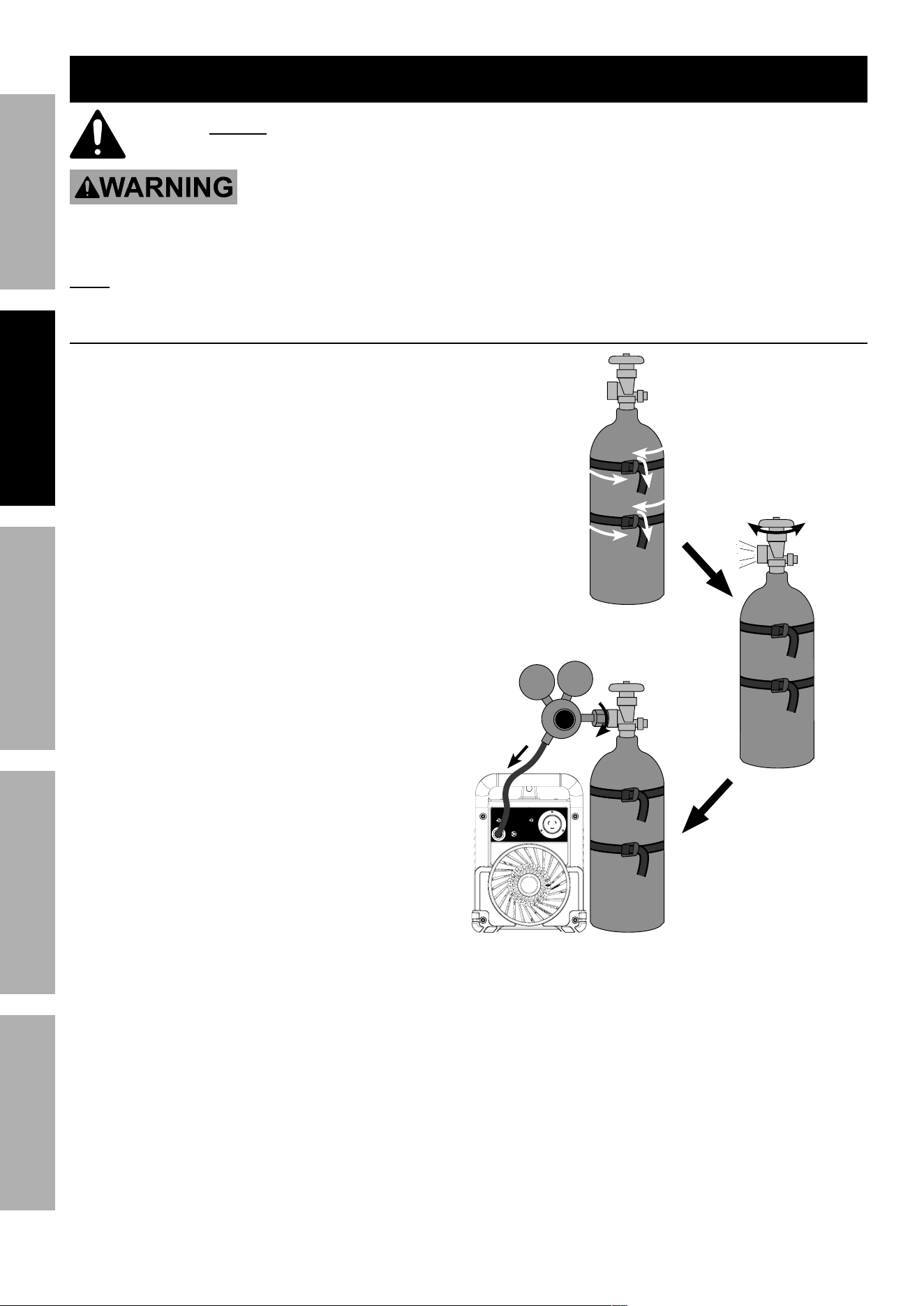
connect Shielding gas
1. With assistance, place an 100% Argon cylinder
(not included) onto a cabinet or cart near the
Welder and secure the cylinder in place with
two straps (not included) to prevent tipping.
2. Remove the cylinder’s cap. Stand to the
side of the valve opening, then open the
valve briefly to blow dust and dirt from the
valve opening. Close the cylinder valve.
3. Close the Regulator’s valve by backing off knob
until it is loose, then thread Regulator onto
cylinder and wrench tighten connection.
4. Attach the Gas Hose (included) to the
Regulator’s Outlet and the Welder’s Gas Inlet.
Wrench-tighten both connections.
Reset
Power Input
Gas Inlet
4
3
Briefly open valve
to clean,
then close
valve.
2
1
Page 7For technical questions, please call 1-888-380-0318.Item 63793
SAFETyMAINTENANcE BASIc WELdINgWELdINg TIpS SETUP
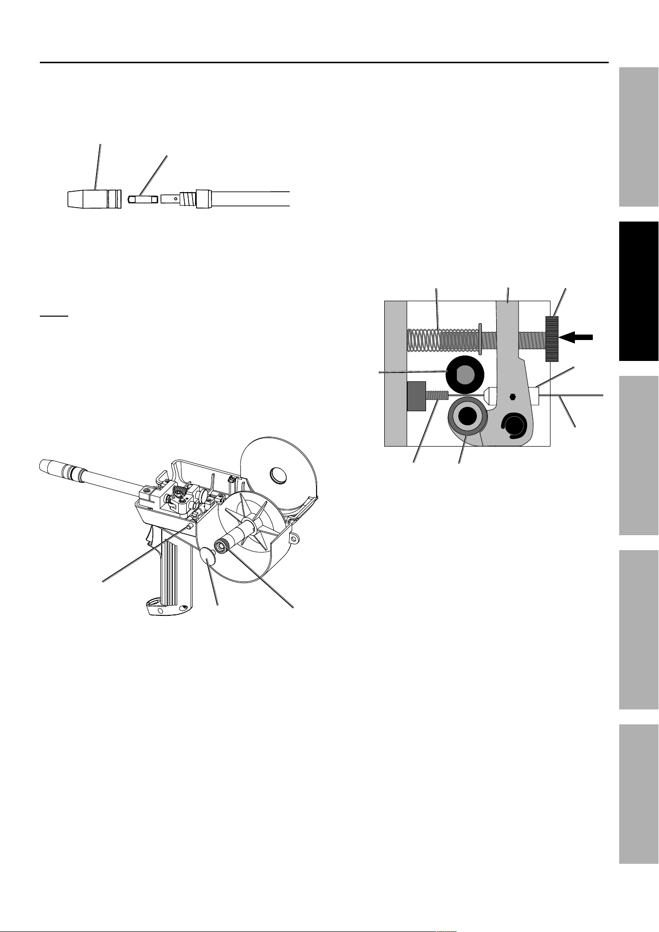
Set Up Spool gun
1. Pull the Nozzle to remove it.
2. Unscrew the Contact Tip
counterclockwise and remove.
Nozzle
contact
Tip
3. Press Spool Cover Release Button,
then open Spool Cover.
4. Remove Spool Lock Knob by turning clockwise.
5. Loosen Spool Tension Knob without removing.
Note: To prevent unraveling, leave
wire secured to Spool.
6. Install Spool so wire will feed over top of Spool.
7. Tighten Spool Tension Knob until
Spool cannot spin freely.
8. Replace Spool Lock Knob by
turning counterclockwise.
Spool
Lock Knob
Spool
Tension
Knob
Spool cover
Release Button
9. Hold end of wire while releasing from
Spool. Cut off any bent wire.
10. Keeping tension on Spool, feed
Wire into Inlet Guide.
11. Loosen Tension Knob.
12. Push on Tension Knob enough to create a
space, between Driver Roller and Tension Roller,
large enough so that Wire will pass through.
13. Push Wire 1/4" into Inlet.
14. Tighten Tension Knob.
Tension
Knob
Tension
Arm
Tension
Roller
Wire
Inlet
guide
drive
Roller
Inlet
Tension
Spring
15. Close Spool Cover.
16. Set Spool Gun down on nonconductive,
nonflammable surface away from
any grounded objects.

Page 8 For technical questions, please call 1-888-380-0318. Item 63793
SAFETy MAINTENANcEBASIc WELdINg WELdINg TIpSSETUP
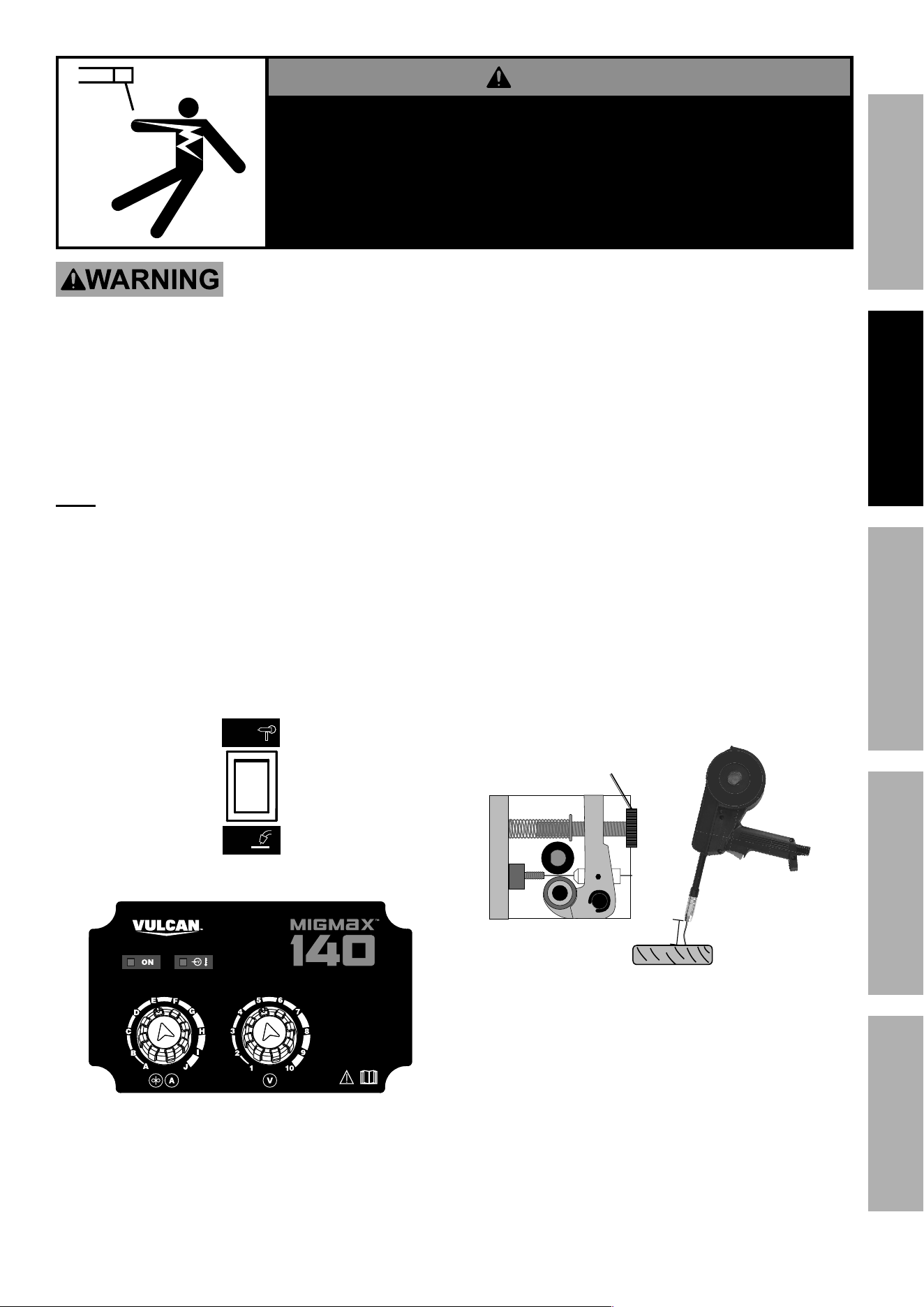
Connect to Vulcan MIGMAX 140
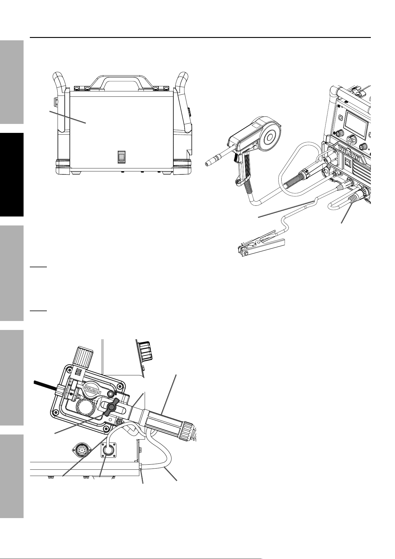
1. Turn Power Switch OFF and unplug welder.
2. Open Door on side of Welder.
3. Remove MIG Gun and Wire Spool, if present.
door
4. Set Polarity to DCEP (Direct
Current Electrode Positive):
a. Connect Black Ground Cable
to Negative Terminal (-).
b. Connect Red Electrode Cable
to Positive Terminal (+).
c. Make sure Cables sit flush in grooves.
groove
5. connect Spool gun:
a. Loosen Knob without removing.
b. Plug Spool Gun Connector
into Spool Gun Socket.
c. Tighten Knob, do not over tighten.
d. Pull on Spool Gun Connector to ensure tight
connection. Re-seat if connection is not tight.
Note: If connection is not tight, arc will not ignite.
Knob
Spool gun
connector
Spool gun
Socket
6. Plug Wire Feed Control Cable into
Wire Feed Control Socket. Secure by
turning collar clockwise until tight.
Note: Plug will only fit one way.
7. Plug Gas Cable into Gas Outlet.
Secure by wrench tightening.
Spool gun
Socket
Wire Feed
control
Socket
gas
Outlet
Wire Feed
control
cable
gas
cable
Page 9For technical questions, please call 1-888-380-0318.Item 63793
SAFETyMAINTENANcE BASIc WELdINgWELdINg TIpS SETUp
dANgER
pARTS MAy BE AT WELdINg VOLTAgE
TO pREVENT ELEcTRIc SHOcK ANd dEATH:
1. Keep hands away from Wire Feed mechanism.
2. close door before plugging in,
3. Stay clear of wire while feeding wire through gun.
TO pREVENT SERIOUS INJURy: protective gear must be worn when using the Welder; minimum
shade number 10 full face shield (or welding mask), ear protection, welding gloves, sleeves and apron,
NIOSH-approved respirator, and fire resistant work clothes without pockets should be worn when welding.
Light from the arc can cause permanent damage to the eyes and skin. do not breathe arc fumes.
8. close door on side of Welder,
making sure it latches.
9. Plug either 120 VAC or 240 VAC Power Cord
into Power Input Socket on back of welder.
Note: Plug will only fit one way.
10. Plug Welder into properly grounded, GFCI
protected, 120 VAC (20 amp rated) outlet or
240 V outlet. The circuit must be equipped with
delayed action-type circuit breaker or fuses.
11. Turn Power Switch ON.
12. On inside of welder,
toggle Spool Gun/MIG Gun switch
to Spool gun.
Spool
Gun
MIG
Gun
Cold
Wire Feed
a. Turn Amperage to A and Voltage to 1.
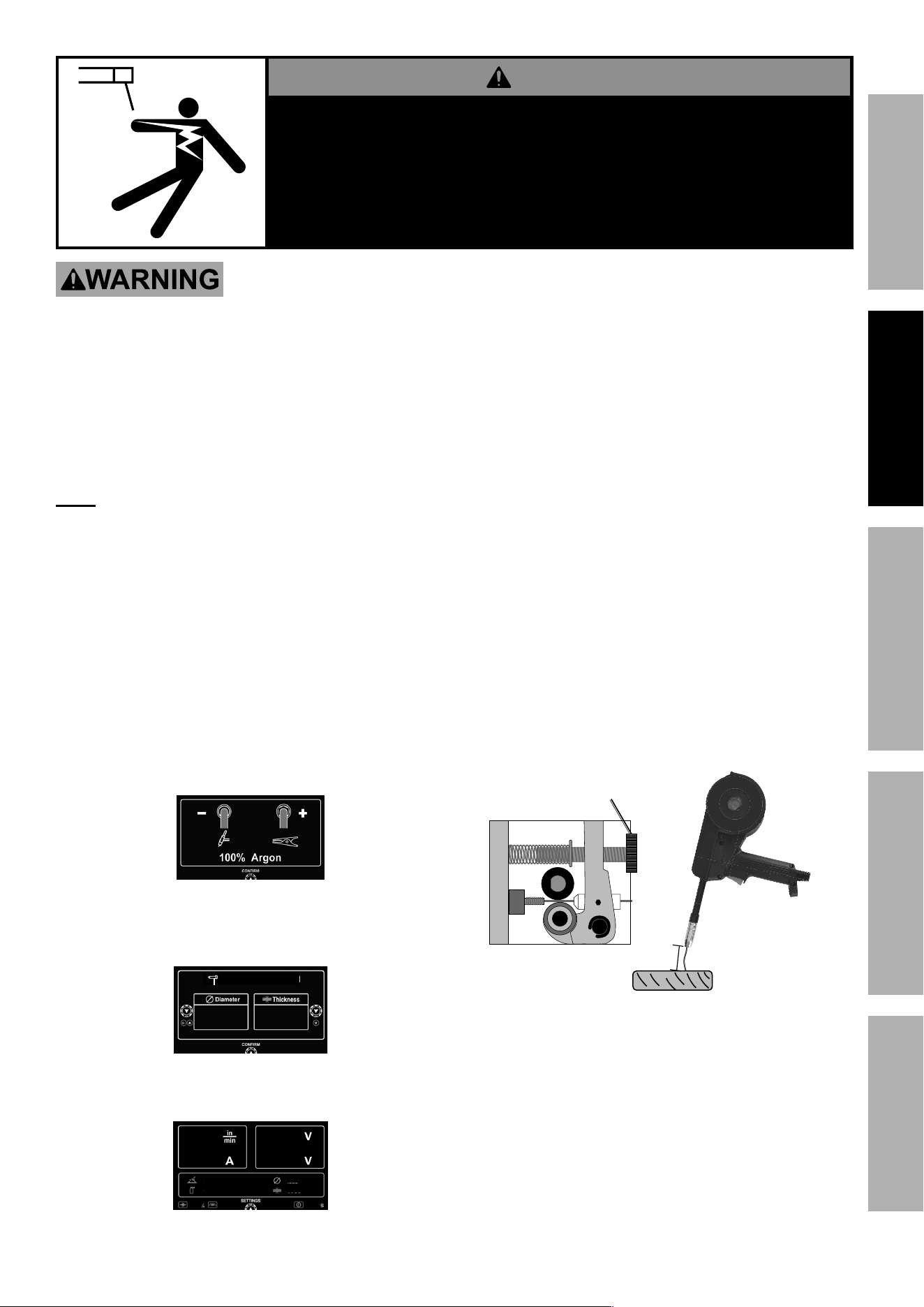
13. check Wire drive Tension:
a. Hold Spool Gun and point it
away from all objects.
b. Press and hold Trigger until at least 2"
of wire sticks out of the Gun. Release
Trigger. Trim wire to 2" as needed.
c. Hold Gun 2 - 3" away from piece of wood.
d. Press Trigger. When Wire touches wood,
it should bend instead of stopping.
• If Wire stops instead of bending,
turn off and unplug welder.
• Slightly tighten Tension Knob.
• Plug welder in and turn power on.
• Repeat steps c. and d. until Wire bends instead
of stopping. Trim wire to 2" as needed.
2-3"
Tension
Knob
Wire Should
Bend
14. Turn Power Switch OFF and unplug welder.
15. Choose Contact Tip same size as
Wire. Slide Contact Tip over Wire.
16. Replace Nozzle, trim wire to 1/2".
17. Set Spool Gun down on nonconductive,
nonflammable surface away from
any grounded objects.
18. Go to Operation on page 14.
Page 10 For technical questions, please call 1-888-380-0318. Item 63793
SAFETy MAINTENANcEBASIc WELdINg WELdINg TIpSSETUP
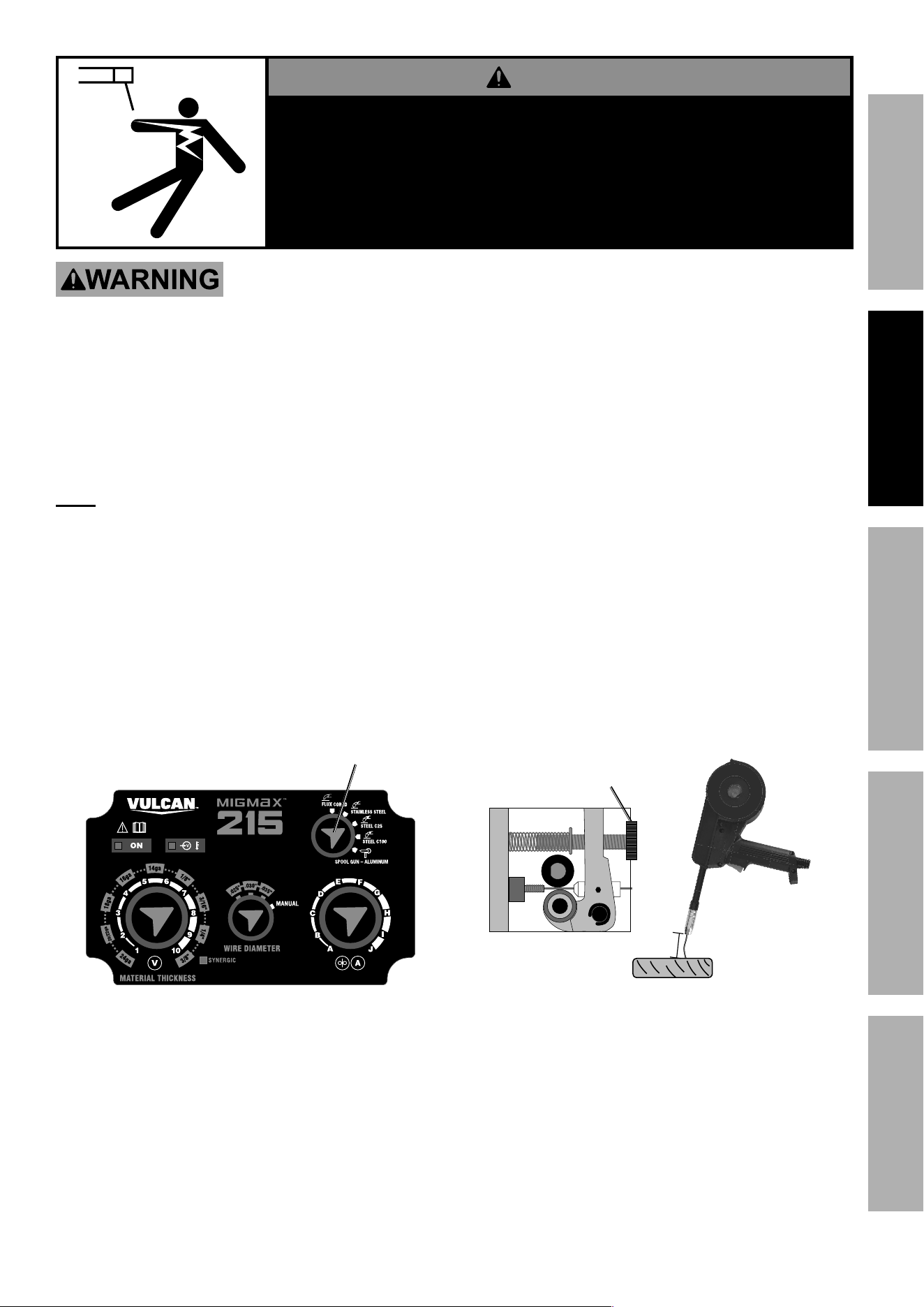
connect to Vulcan MIgMAX 215
1. Turn Power Switch OFF and unplug welder.
2. Open Door on side of welder.
3. Remove MIG Gun and Wire Spool, if present.
door
4. Set Polarity to DCEP (Direct
Current Electrode Positive):
a. Connect Black Ground Cable
to Negative Terminal (-).
b. Connect Red Electrode Cable
to Positive Terminal (+).
c. Make sure Cables sit flush in grooves.
groove
5. connect Spool gun:
a. Loosen Knob without removing.
b. Plug Spool Gun Connector
into Spool Gun Socket.
c. Tighten Knob, do not over tighten.
d. Pull on Spool Gun Connector to ensure tight
connection. Re-seat if connection is not tight.
Note: If connection is not tight, arc will not ignite.
Knob
Spool gun
connector
Spool gun
Socket
6. Plug Wire Feed Control Cable into
Wire Feed Control Socket. Secure by
turning collar clockwise until tight.
Note: Plug will only fit one way.
7. Plug Gas Cable into Gas Outlet.
Secure by wrench tightening.
Spool gun
Socket
Wire Feed
control
Socket
gas
Outlet
Wire Feed
control
cable
gas
cable
Page 11For technical questions, please call 1-888-380-0318.Item 63793
SAFETyMAINTENANcE BASIc WELdINgWELdINg TIpS SETUp
dANgER
pARTS MAy BE AT WELdINg VOLTAgE
TO pREVENT ELEcTRIc SHOcK ANd dEATH:
1. Keep hands away from Wire Feed mechanism.
2. close door before plugging in,
3. Stay clear of wire while feeding wire through gun.
TO pREVENT SERIOUS INJURy: protective gear must be worn when using the Welder; minimum
shade number 10 full face shield (or welding mask), ear protection, welding gloves, sleeves and apron,
NIOSH-approved respirator, and fire resistant work clothes without pockets should be worn when welding.
Light from the arc can cause permanent damage to the eyes and skin. do not breathe arc fumes.
8. close door on side of Welder,
making sure it latches.
9. Plug either 120 VAC or 240 VAC Power Cord
into Power Input Socket on back of welder.
Note: Plug will only fit one way.
10. Plug welder into a properly grounded, GFCI
protected, 120 VAC (20 amp rated) outlet or
240 V outlet. The circuit must be equipped with
delayed action-type circuit breaker or fuses.
11. Turn Power Switch ON.
12. Turn Process Selection Knob to Spool gun.
13. Turn Voltage to 1, Amperage to A and
Wire Diameter to MANUAL.
process
Selection Knob
14. check Wire drive Tension:
a. Hold Spool Gun and point it
away from all objects.
b. Press and hold Trigger until at least 2"
of wire sticks out of the Gun. Release
Trigger. Trim wire to 2" as needed.
c. Hold Gun 2 - 3" away from piece of wood.
d. Press Trigger. When Wire touches
wood, it should bend instead of
stopping. Release Trigger.
• If Wire stops instead of bending,
turn off and unplug welder.
• Slightly tighten Tension Knob.
• Plug welder in and turn power on.
• Repeat steps c. and d. until Wire bends instead
of stopping. Trim wire to 2" as needed.
2-3"
Tension
Knob
Wire Should
Bend
15. Turn Power Switch OFF and unplug welder.
16. Choose Contact Tip same size as
Wire. Slide Contact Tip over Wire.
17. Replace Nozzle, trim wire to 1/2".
18. Set Spool Gun down on nonconductive,
nonflammable surface away from
any grounded objects.
19. Go to Operation on page 14.
Page 12 For technical questions, please call 1-888-380-0318. Item 63793
SAFETy MAINTENANcEBASIc WELdINg WELdINg TIpSSETUP
connect to Vulcan OMNIpRO 220
1. Turn Power Switch OFF and unplug Welder.
2. Open Door on side of Welder.
door
3. connect Spool gun:
a. Loosen Knob without removing.
b. Plug Spool Gun Connector
into Spool Gun Socket.
c. Tighten Knob, do not over tighten.
d. Pull on Spool Gun Connector to ensure tight
connection. Re-seat if connection is not tight.
Note: If connection is not tight, arc will not ignite.
4. Plug Wire Feed Control Cable into
Wire Feed Control Socket. Secure by
turning collar clockwise until tight.
Note: Plug will only fit one way.
5. Plug Gas Cable into Gas Outlet.
Secure by wrench tightening.
Knob
Spool gun
connector
gas
cable
Spool gun
Socket
Wire Feed
control
Socket
Wire Feed
control
cable
gas
Outlet
6. Plug Ground Clamp Cable into Negative Socket.
Twist clockwise all the way to lock in place.
7. Plug Wire Feed Power Cable into Positive Socket.
Twist clockwise all the way to lock in place.
ground
clamp
cable
Wire Feed
power cable
Page 13For technical questions, please call 1-888-380-0318.Item 63793
SAFETyMAINTENANcE BASIc WELdINgWELdINg TIpS SETUp
dANgER
pARTS MAy BE AT WELdINg VOLTAgE
TO pREVENT ELEcTRIc SHOcK ANd dEATH:
1. Keep hands away from Wire Feed mechanism.
2. close door before plugging in,
3. Stay clear of wire while feeding wire through gun.
TO pREVENT SERIOUS INJURy: protective gear must be worn when using the Welder; minimum
shade number 10 full face shield (or welding mask), ear protection, welding gloves, sleeves and apron,
NIOSH-approved respirator, and fire resistant work clothes without pockets should be worn when welding.
Light from the arc can cause permanent damage to the eyes and skin. do not breathe arc fumes.
8. close door on side of Welder,
making sure it latches.
9. Plug either 120 VAC or 240 VAC Power Cord
into Power Input Socket on back of welder.
Note: Plug will only fit one way.
10. Plug Welder into properly grounded, GFCI
protected, 120 VAC (20 amp rated) outlet or
240 V outlet. The circuit must be equipped with
delayed action-type circuit breaker or fuses.
11. Turn Power Switch ON.
12. Push Home button.
13. Turn Main Knob until desired
Spool Gun/Wire Type process
appears on screen.
14. Press Main Knob. Confirm correct
Gas is connected to welder.
15. Press Main Knob. Make sure Diameter
and Thickness are set to lowest settings
by turning Left and Right Knobs.
.030" 16ga
Spool Gun 4043 Al
16. Press Main Knob. Ready to
check Wire Drive Tension.
348 15.5
0.0
0
.030"
0.0
25 5
16ga
Spool Gun 4043 Al
100% Ar
17. check Wire drive Tension:
a. Hold Spool Gun and point it
away from all objects.
b. Press and hold Trigger until at least 2" of wire
sticks out of the Gun. Trim wire to 2" as needed.
c. Hold Gun 2 - 3" away from piece of wood.
d. Press Trigger. When Wire touches wood,
it should bend instead of stopping.
• If Wire stops instead of bending,
turn off and unplug welder.
• Slightly tighten Tension Knob.
• Plug welder in and turn power on.
• Reset Welder to desired process
and check settings.
• Repeat steps c. and d. until Wire bends instead
of stopping. Trim wire to 2" as needed.
2-3"
Tension
Knob
Wire Should
Bend
18. Turn Power Switch OFF and unplug welder.
19. Choose Contact Tip same size as
Wire. Slide Contact Tip over Wire.
20. Replace Nozzle, trim wire to 1/2".
21. Set Spool Gun down on nonconductive,
nonflammable surface away from
any grounded objects.
Page 14 For technical questions, please call 1-888-380-0318. Item 63793
SAFETy MAINTENANcEBASIc WELdINg WELdINg TIpSSETUP
Operation
Read the ENTIRE IMpORTANT SAFETy INFORMATION section at the beginning of this
manual including all text under subheadings therein before set up or use of this product.
TO pREVENT SERIOUS INJURy ANd dEATH:
do not weld without grounding clamp.
When the operator is not holding the Spool gun, it must be sitting on a nonconductive, nonflammable
surface.
Only hold Spool gun with an electrically insulated welding glove.
TO pREVENT SERIOUS INJURy:
protective gear must be worn when using the Welder; minimum shade number 10 full face
shield (or welding mask), ear protection, welding gloves, sleeves and apron, NIOSH-approved
respirator, and fire resistant work clothes without pockets should be worn when welding.
TO pREVENT dEATH FROM ASpHyXIATION:
do not open gas without proper ventilation. Fix gas leaks immediately. Shielding gas can displace
air and cause rapid loss of consciousness and death. Shielding gas without carbon dioxide can be
even more hazardous because asphyxiation can start without feeling shortness of breath.
Refer to Basic Welding section in your Vulcan welder’s manual
for MIg duty cycle, Setting Up The Weld, grounding Workpiece,
Settings, Shielding gas Use and Basic Welding Technique.
Substitute instructions below for Basic Welding Technique in welder’s manual.
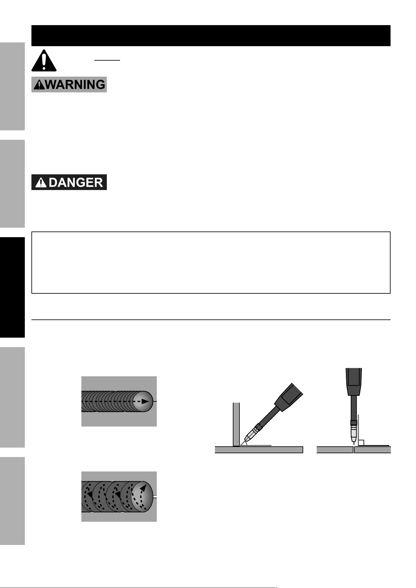
Basic Welding Technique
1. Press (and hold) Spool Gun Trigger and contact
the area to be welded with wire to ignite arc.
• Narrow Weld: Push the wire in a steady
straight line. This is called a stringer bead.
Stringer Bead
• Wide Weld: Push the wire back and forth
across the joint. This is called a weave bead
and takes practice to perform properly.
Weave Bead
2. Direct the welding wire straight into the join:.
• 45° angle for fillet welds.
• 90° angle for butt welds,
Weld MIg gun angles,
viewed from front of weld joint.
45°
fillet weld joint
90°
butt weld joint
Page 15For technical questions, please call 1-888-380-0318.Item 63793
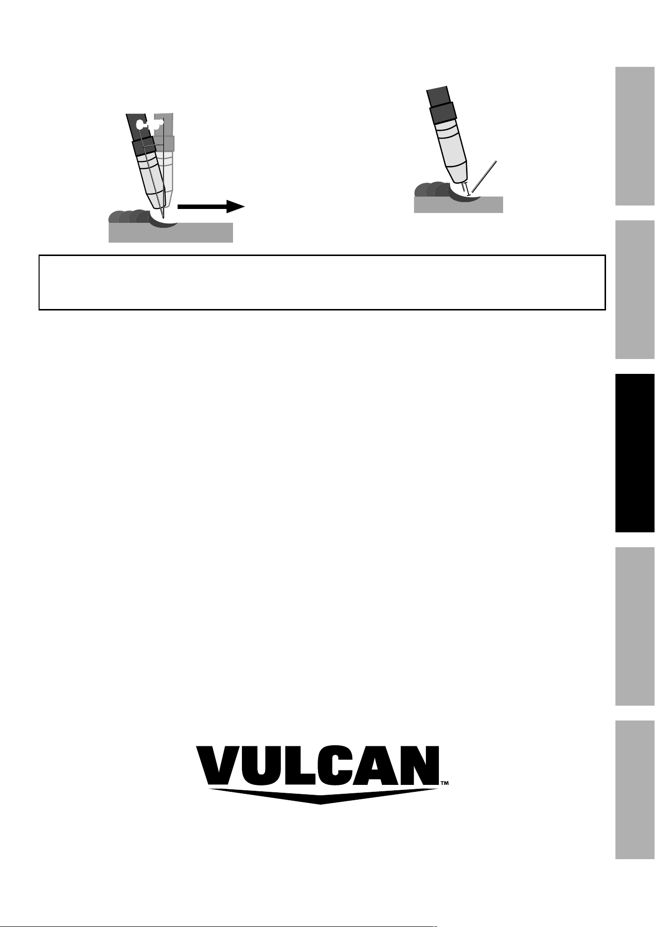
SAFETyMAINTENANcE BASIc WELdINgWELdINg TIpS SETUP
3. The Spool Gun should be tilted so that wire
is angled anywhere from straight on and 15°
away from the direction you are welding. The
amount of tilt is called the push angle.
Weld
direction
push Angle
0-15°
4. The Contact Tip should remain within 1/2"
of the work surface. This distance is called
CTWD - Contact Tip to Work Distance.
cTWd
(up to 1/2")
Refer to Basic Welding section in your Vulcan welder’s
manual for remaining welding instructions.
Page 16 For technical questions, please call 1-888-380-0318. Item 63793
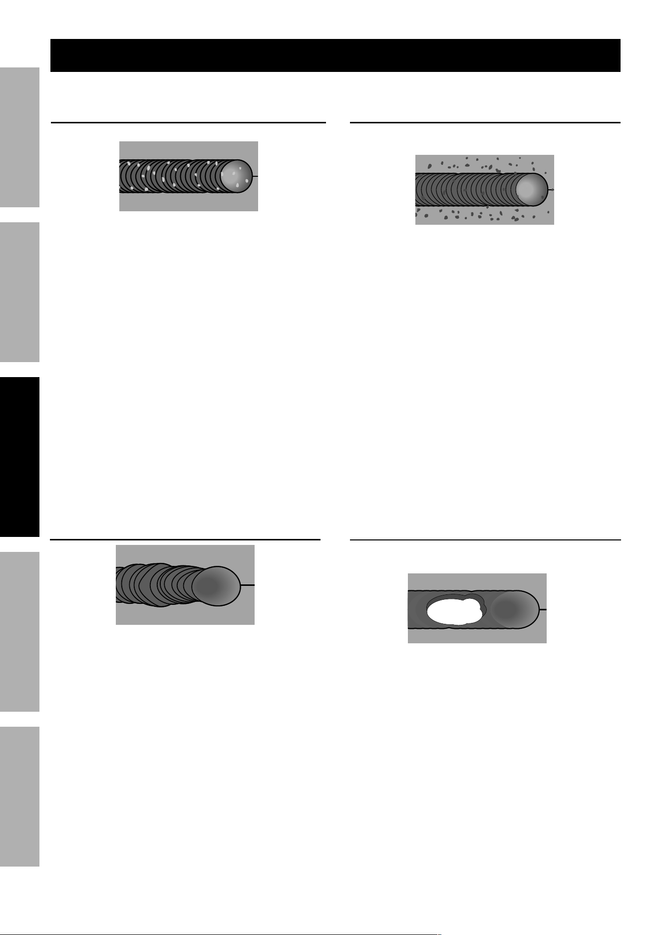
SAFETy MAINTENANcEBASIc WELdINg WELdINg TIpSSETUP
Burn-Through
Base material melts away,
leaving a hole in the weld.
pOSSIBLE cAUSES ANd SOLUTIONS
1. Workpiece overheating:
Reduce current and/or wire feed speed.
2. Travel speed too slow:
Increase travel speed and ensure
that travel speed is kept steady.
3. Excessive material at weld:
Reduce wire feed speed.
TOP
VIEW
crooked/Wavy Bead
pOSSIBLE cAUSES ANd SOLUTIONS
1. Inaccurate welding:
Use two hands or rest hand on steady surface.
2. Inconsistent travel speed:
Maintain steady travel speed.
3. cTWd too long:
Reduce CTWD.
TOP
VIEW
porosity
Small cavities or holes in the bead.
pOSSIBLE cAUSES ANd SOLUTIONS
1. Incorrect polarity:
Check that polarity is set correctly
for type of welding.
2. Insufficient shielding gas (MIG only):
Increase flow of gas.
Clean nozzle.
Maintain proper CTWD.
3. Incorrect shielding gas (MIG only):
Use shielding gas recommended by wire supplier.
4. dirty workpiece or welding wire:
Clean workpiece down to bare metal.
Make certain that wire is clean and free
from oil, coatings, and other residues.
5. Inconsistent travel speed:
Maintain steady travel speed.
6. cTWd too long:
Reduce CTWD.
TOP
VIEW
Excessive Spatter
Fine spatter is normal.
Spatter that is grainy and large is a problem.
pOSSIBLE cAUSES ANd SOLUTIONS
1. dirty workpiece or welding wire:
Clean workpiece down to bare metal.
Make certain that wire is clean and free
from oil, coatings, and other residues.
2. Incorrect polarity:
Check that polarity is set correctly
for type of welding.
3. Insufficient shielding gas (MIG only):
Increase flow of gas.
Clean nozzle.
Maintain proper CTWD.
4. Wire feeding too fast:
Reduce wire feed speed.
5. cTWd too long:
Reduce CTWD.
TOP
VIEW
Weld problems
Page 17For technical questions, please call 1-888-380-0318.Item 63793
SAFETyMAINTENANcE BASIc WELdINgWELdINg TIpS SETUP
Maintenance and Service
TO pREVENT SERIOUS INJURy, FIRE ANd BURNS:
Unplug the welder, rest the Spool gun on a heat-proof, electrically non-conductive surface,
and allow all parts of the Welder to cool thoroughly before service.
1. BEFORE EAcH USE, inspect the general
condition of the Spool Gun. Check for:
• loose hardware,
• misalignment or binding of moving parts,
• damaged cord/electrical wiring,
• frayed or damaged cables,
• cracked or broken parts, and
• any other condition that may
affect its safe operation.
2. AFTER EVERy USE, inspect and
clean Nozzle and Contact Tip.
3. AFTER EVERy USE, Store in a
clean and dry location.
4. pERIOdIcALLy, clean Barrel, replace Inlet Guide
Nozzle and contact Tip Inspection and cleaning
1. Make sure that the Spool gun is completely
cool and that the power cord is unplugged
from the electrical outlet before proceeding.
2. Pull the Nozzle to remove it.
3. Scrub the interior of the Nozzle
clean with a wire brush.
4. Examine the end of the Nozzle. The end should be
flat and even. If the end is uneven, chipped, melted,
cracked, or otherwise damaged, replace Nozzle.
5. Unscrew the Contact Tip counterclockwise
and slide it off the welding wire to remove.
6. Scrub the outside of the Tip clean
with a wire brush. Clean out the inside of the
tip with a tip cleaner (sold separately).
7. Examine the shape of the hole at the end of the
Contact Tip. It should be an even circle; if it is
oblong or has any bulges in it, replace Contact Tip.
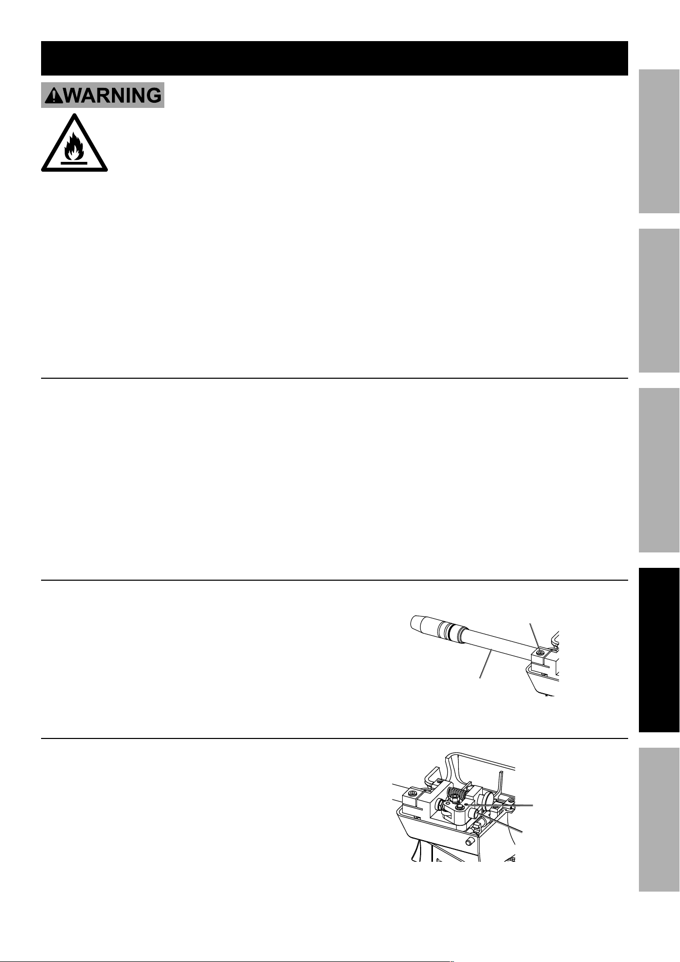
cleaning Barrel
1. Remove Nozzle and Contact Tip.
2. Remove Hex Bolt, then pull Barrel out.
3. Using compressed air, blow out Barrel.
4. Replace Barrel, Contact Tip and Nozzle.
Hex
Bolt
Barrel
Replacing Inlet guide
1. Remove Hex Set Screw.
2. Pull out Inlet Guide.
3. Replace Inlet Guide.
4. Replace Hex Set Screw.
dO NOT overtighten. Ensure Inlet guide
is snug. Overtightening will cause
permanent damage to Inlet guide.
Hex Set
Screw
Inlet
guide

Page 18 For technical questions, please call 1-888-380-0318. Item 63793
SAFETy MAINTENANcEBASIc WELdINg WELdINg TIpSSETUP
Troubleshooting
problem possible causes Likely Solutions
Wire feed motor
runs but wire does
not feed properly
1. Tension Knob is too tight.
2. Damaged Gun, cable, or liner assembly.
3. Tension Knob is too tight.
1. Tighten Tension Knob so it applies only
enough pressure to prevent continued
spinning after the Gun Trigger is released.
2. Have a qualified technician inspect these
parts and replace as necessary.
3. Loosen Tension Knob so it applies only
enough pressure to prevent continued
spinning after the Gun Trigger is released.
Wire creates a bird’s
nest during operation
1. Tension Knob is too tight.
2. Incorrect Contact Tip size.
3. Damaged liner.
1. Loosen Tension Knob
2. Replace with the proper tip for wire used.
3. Have a qualified technician inspect
and repair/replace as necessary.
Wire stops
during welding
1. Gun liner is clogged or worn.
2. Wire is tangled on the spool.
3. Tension Roller is not making
enough contact with wire.
1. Check gun liner for obstruction, blow out with
compressed air. Have liner replaced if necessary.
2. Check wire for cross winding or tangled spool.
3. Check Tension Knob and ensure it is set properly.
Wire feeds, but arc
does not ignite
1. Improper ground connection.
2. Improperly sized Contact Tip.
3. Excessively worn Contact Tip.
4. Dirty Contact Tip.
1. Make certain that the workpiece is contacted
properly by the Ground Clamp and that
the workpiece is properly cleaned near the
ground clamp and the welding location.
2. Verify that Contact Tip is the proper size
for welding wire. If needed, replace
Contact Tip with proper size and type.
3. Check that the hole in the tip is not
deformed or enlarged. If needed, replace
Contact Tip with proper size and type.
4. Properly clean Contact Tip.
Porosity in the
weld metal
1. Gun is being used too far away from workpiece.
2. Dirty welding wire is introducing
contamination into the weld.
1. Check CTWD (contact tip to work distance).
2. Make certain that welding wire is clean
and free of rust and residues.
Welding arc
not stable
1. Wire not feeding properly.
2. Incorrect or damaged Contact Tip.
3. Loose Gun cable or ground cable.
4. Damaged Gun or loose connection within Gun.
5. Gas coverage may be insufficient or too high.
6. Poor connection with workpiece.
1. See first Troubleshooting section above.
2. Replace Contact Tip.
3. Check to ensure that all connections are tight.
4. Have a qualified technician inspect
and repair/replace as necessary.
5. Ensure gas flow rate is set according to Settings Chart.
Make sure Gun Cable Connector is fully inserted into
Wire Feed mechanism with no O-Rings exposed.
6. Check the ground clamp connection to the workpiece
and machine. Ensure the Gun is properly secured.
Follow all safety precautions whenever diagnosing or servicing the equipment.
Page 19For technical questions, please call 1-888-380-0318.Item 63793
SAFETyMAINTENANcE BASIc WELdINgWELdINg TIpS SETUP
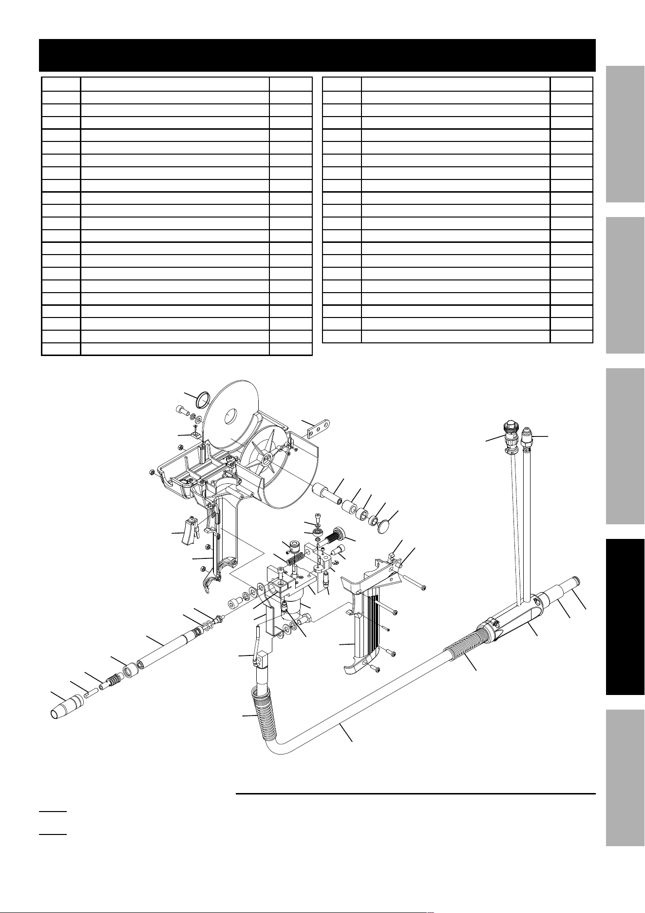
parts List and diagram
part description Qty
1 Handle 1
2 Trigger 1
3 Block 1
4 Cover 1
5 Hanger Hook 1
6 Spool Shaft 1
7 Spool Tensioner 1
8 Spacer 1
9 Spool Tension Knob 1
10 Spool Lock Knob 1
11 Latch 1
12 Spool Cover Release Button 1
14 Drive Roller 1
15 Tension Spring 1
16 Bushing 1
17 Tension Roller 1
18 Tension Knob 1
19 Inlet Guide 1
20 Tension Arm 1
21 Tension Arm Shaft 1
22 Bracket 1
part description Qty
23 Motor And Gear Box 1
24 Gas Connector 1
25 Wire Feeder Assembly 1
26 Conducting Bar 1
27 Liner Assembly 1
28 O-Ring 7.65X1.78 2
29 Barrel 1
30 Insulator 1
31 Gas Diffuser 1
32 Contact Tip 4
33 Nozzle 12mm 1
35 Internal Gas Hose 1
36 Front Spring Cable Support 1
37 Cable Assembly 1
38 Back Spring Cable Support 1
39 Connector 1
40 Connector Insulator 1
41 Connector 1
42 Gas Hose Plug 1
43 Wire Feed Plug 1
33
31
30
32
29
28
27
26
23
22
14
21
20
19
18
16
17
15
2
1
3
4
1
5
9
8
7
6
10
11
12
35
36
37
38
39
41
43
24
25
40
42
Record product’s Serial Number Here:
Note: If product has no serial number, record month and year of purchase instead.
Note: Some parts are listed and shown for illustration purposes only,
and are not available individually as replacement parts.

3491 Mission Oaks Blvd. • PO Box 6009 • Camarillo, CA 93011 • 1-888-380-0318
Limited 90 Day Warranty
Harbor Freight Tools Co. makes every effort to assure that its products meet high quality and durability standards,
and warrants to the original purchaser that this product is free from defects in materials and workmanship for the
period of 90 days from the date of purchase. This warranty does not apply to damage due directly or indirectly,
to misuse, abuse, negligence or accidents, repairs or alterations outside our facilities, criminal activity, improper
installation, normal wear and tear, or to lack of maintenance. We shall in no event be liable for death, injuries
to persons or property, or for incidental, contingent, special or consequential damages arising from the use of
our product. Some states do not allow the exclusion or limitation of incidental or consequential damages, so the
above limitation of exclusion may not apply to you. THIS WARRANTY IS EXPRESSLY IN LIEU OF ALL OTHER
WARRANTIES, EXPRESS OR IMPLIED, INCLUDING THE WARRANTIES OF MERCHANTABILITY AND FITNESS.
To take advantage of this warranty, the product or part must be returned to us with transportation charges
prepaid. Proof of purchase date and an explanation of the complaint must accompany the merchandise.
If our inspection verifies the defect, we will either repair or replace the product at our election or we may
elect to refund the purchase price if we cannot readily and quickly provide you with a replacement. We will
return repaired products at our expense, but if we determine there is no defect, or that the defect resulted
from causes not within the scope of our warranty, then you must bear the cost of returning the product.
This warranty gives you specific legal rights and you may also have other rights which vary from state to state.
pLEASE REAd THE FOLLOWINg cAREFULLy
THE MANUFACTURER AND/OR DISTRIBUTOR HAS PROVIDED THE PARTS LIST AND ASSEMBLY DIAGRAM
IN THIS MANUAL AS A REFERENCE TOOL ONLY. NEITHER THE MANUFACTURER OR DISTRIBUTOR
MAKES ANY REPRESENTATION OR WARRANTY OF ANY KIND TO THE BUYER THAT HE OR SHE IS
QUALIFIED TO MAKE ANY REPAIRS TO THE PRODUCT, OR THAT HE OR SHE IS QUALIFIED TO REPLACE
ANY PARTS OF THE PRODUCT. IN FACT, THE MANUFACTURER AND/OR DISTRIBUTOR EXPRESSLY
STATES THAT ALL REPAIRS AND PARTS REPLACEMENTS SHOULD BE UNDERTAKEN BY CERTIFIED AND
LICENSED TECHNICIANS, AND NOT BY THE BUYER. THE BUYER ASSUMES ALL RISK AND LIABILITY
ARISING OUT OF HIS OR HER REPAIRS TO THE ORIGINAL PRODUCT OR REPLACEMENT PARTS
THERETO, OR ARISING OUT OF HIS OR HER INSTALLATION OF REPLACEMENT PARTS THERETO.