To Reduce The Risk Of Injury, User Must Read And
Understand Operator’s Manual. Save These Instructions For Future Reference.
260-9473
6/12V 2A High-frequency Charger

TABLE OF CONTENTS
Safety Symbols..............................................................................Page 3
Safety Information..........................................................................Page 4
Important Safety Instructions........................................................Page 5
Personal Precautions.....................................................................Page 6
Preparing to Charge.......................................................................Page 7
DC Connection Precautions..........................................................Page 7
Specification...................................................................................Page 8
Connection......................................................................................Page 8
LED Display Status........................................................................ Page 9
Operating Instructions...................................................................Page 9
After Using....................................................................................Page 10
Maintenance.................................................................................Page 10
Parts List.......................................................................................Page 11
Trouble Shooting..........................................................................Page 11
Warranty........................................................................................Page 15

Page 3
SAFETY SYMBOLS
Some of the following symbols may be used on your charger. Please study
them and learn their meaning. Proper interpretation of these symbols will allow
better and safer operation of the charger.
Symbol Name Reason/Solution
V Volts Voltage
A Amperes Current
Hz Hertz Frequency
W Watts Power
~ Alternating current Type of current
Direct current Type or characteristic of current
Class II construction Double-insulated construction
Read the operator’s
manual
To reduce the risk of injury, read and
understand the operator’s manual
Wear safety equipment
Operation of the charger can result in
damage to unprotected person
Warning symbol Alerts user to warning message
Electric shock symbol
Connect only to properly grounded
outlets. Replace defective cords or
wire immediately.
Explosive gas symbol
Risk of explosive gases during normal
operation of a lead-acid battery
Page 4
SAFETY INFORMATION
The purpose of safety symbols is to attract our attention to possible dangers. The
safety symbols, and the explanations with them, deserve your careful attention and
understanding. The symbol warnings do not by themselves eliminate any danger.
The instructions and warnings they give are no substitutes for proper accident pre-
vention measures.
Be sure to read and understand all safety instructions in this
manual, including all safety alert symbols, such as “DANGER”, “WARNING” and
“CAUTION” before using this battery charger. Failure to follow all instructions
listed below may result in electric shock, fire and/or serious personal injury.
SYMBOL MEANING
SAFETY ALERT SYMBOL: Indicates DANGER, WARNING or CAUTION.
May be used in conjunction with other symbols or pictographs.
Failure to obey this safety warning WILL result in death or serious
injury to yourself or to others. Always follow the safety precautions to reduce the risk
of fire, electric shock and personal injury.
Failure to obey this safety warning CAN result in death or
serious injury to yourself or to others. Always follow the safety precautions to
reduce the risk of fire, electric shock and personal injury.
Failure to obey this safety warning MAY result in personal
injury to yourself or others, or property damage. Always follow the safety precautions
to reduce the risk of fire, electric shock and personal injury.

Page 5
1. IMPORTANT SAFETY INSTRUCTIONS
1.1
1.2
1.3
1.4
1.5
1.6
1.7
1.8
1.9
SAVE THESE INSTRUCTIONS
This manual contains important safety
and operating instructions for this
battery charger.
Do not use the charger in rain, snow or
wet environment.
Use of an attachment not recommend-
ed or sold by the battery charger
manufacturer may result
in a risk of fire, electric shock, or injury
to persons.
To reduce risk of damage to electric
plug and cord, pull by plug rather than
cord when
disconnecting charger.
Do not use an extension cord with this
item.
Do not operate charger with damaged
cord or plug – replace the cord or plug
immediately.
Do not operate charger if it has
received a sharp blow, been dropped,
or otherwise damaged in any way; take
it to a qualified serviceman.
Do not disassemble charger; take it to
a qualified technician when service or
repair is required.
Incorrect reassembly may result in a
risk of electric shock or fire.
To reduce risk of electric shock,
unplug charger from outlet before
attempting any maintenance
or cleaning.
1.11
1.12
1.13
1.14
1.15
1.16
1.17
1.18
1.19
1.20
1.21
Only use a charger to charge lead-acid
batteries. It is not used to supply
power to low-voltage electrical
systems other than starter motor
applications. Do not use battery
charger for charging dry-cell batteries
that are commonly used with home
appliances. These batteries may burst
and cause injury to persons and
damage to property.
Never charge from a damaged or
frozen battery.
Do not turn on equipment that battery
is connected to while charging.
Wear splash-resistant safety goggles
and heavy-duty rubber work gloves
whenever connecting, disconnecting,
or working near battery. Battery acid
can cause permanent blindness.
Maintain labels and nameplates on the
charger. These carry important safety
information. If it cannot be read or lost,
please contact the local supplier for
replacement.
This product is not a toy. Keep it out of
reach of children.
Before connecting the cable of the
quick connector to the battery or
performing any inspection, mainte-
nance, or cleaning procedures, please
disconnect the quick connector.
Do not attempt to charge non-re-
chargeable, damaged, or defective
batteries.
Do not charge more than one battery
at one time.
Remove the charger from the power
socket, unplug the quick connector,
and disconnect the battery clip (if
used) after completion.
Have your charger serviced by a
qualified repair person using only
published by battery manufacturer
and manufacturer of any equipment
you intend to use in vicinity of
battery. Review cautionary marking
on these products and on engine.
1.10
WORKING IN VICINITY OF A
LEAD-ACID BATTERY IS DANGER-
OUS. BATTERIES GENERATE
EXPLOSIVE GASES DURING
NORMAL BATTERY OPERATION.
FOR THIS REASON, IT IS OF
UTMOST IMPORTANCE THAT YOU
FOLLOW THE INSTRUCTIONS
EACH TIME YOU USE THE CHAR-
GER.
To reduce risk of battery explosion,
follow these instructions and those
a.
b.
RISK OF EXPLOSIVE GASES
Page 6
1.22
1.23
1.24
1.25
1.27
1.26
identical replacement parts. This will
ensure that the safety of the charger is
maintained.
Do not use charger while you are tired
or under the influence of drugs, alcohol
or medication. A moment of inattention
while operating charger may result in
serious personal injury.
Do not leave charger or battery
unchecked for extended periods of
time to reduce risk.
Before moving charger, disconnect
power supply and battery, then allow
charger to cool.
Do not allow children to play with or
near this item.
Use as intended only.
People with pacemakers should
consult their physician(s) before use.
Electromagnetic fields in close proxim-
ity to heart pacemaker could cause
pacemaker interference or pacemaker
failure.In addition, people with
pacemakers should:
• Avoid operating alone.
• Properly maintain and inspect to
avoid electrical shock.
2.2
2.3
2.4
2.1
Consider having someone close
enough by to come to your aid when
you work near a lead-acid battery.
Have plenty of fresh water and soap
nearby in case battery acid contacts
skin, clothing, or eyes.
Wear complete eye protection and
clothing protection. Avoid touching
eyes while working near
battery.
If battery acid contacts skin or
clothing, wash immediately with soap
and water. If acid enters eye, immedi-
ately flood eye with running cold water
for at least 10 minutes and get medical
attention immediately.
2.6
2.7
2.5
NEVER smoke or allow a spark or
flame in vicinity of battery or engine.
Be extra cautious to reduce risk of
dropping a metal tool onto battery. It
might spark or short-circuit battery or
other electrical part that may cause
explosion.
Remove personal metal items such as
rings, bracelets, necklaces, and
watches when working with a lead-ac-
id battery. A lead-acid battery can
produce a short-circuit current high
enough to weld a ring or the like to
metal, causing a severe burn.
1.28
1.29
1.30
The warnings, precautions, and
instructions discussed in this instruc-
tion manual cannot cover all possible
conditions and situations that may
occur. It must be understood by the
operator that common sense and
caution are factors which cannot be
built into this product, but must be
supplied by the operator.
Inspect before every use; do not use if
parts are loose or damaged.
The Charger has a built in temperature
protection mode, which it will enter
automatically if the unit overheats.
When the temperature has dropped to
a normal level, the charger will restart
normal charging automatically.
The charger will only function if the clamp
voltage is 3.5V or higher. If lower then this
unit will not function.
SAVE THESE INSTRUCTIONS.
• Properly ground power cord. Ground
Fault Circuit Interrupter (GFCI) should
also be implemented – it prevents
sustained electrical shock.
2. PERSONAL PRECAUTIONS
Page 7
3.2
3.3
3.4
3.1
If necessary to remove battery from
vehicle to charge, always remove
grounded terminal from battery first.
Make sure all accessories in the
vehicle are off, so as not to cause an
arc.
Be sure area around battery is well
ventilated while battery is being
charged.
Clean battery terminals. Be careful to
keep corrosion from coming in contact
with eyes.
Add distilled water in each cell until
battery acid reaches level specified by
battery manufacturer. Do not overfill.
3.5
3.6
3.7
For a battery without removable cell
caps, such as valve regulated lead
acid batteries, carefully follow manu-
facturer’s recharging instructions.
Study all battery manufacturer’s
specific precautions while charging
and recommended rates
of charge.
Determine voltage of battery by
referring to vehicle owner’s manual
and make sure it matches output
rating of battery charger.
Do not place charger or electrical
connections on ground or floor.
3. PREPARING TO CHARGE
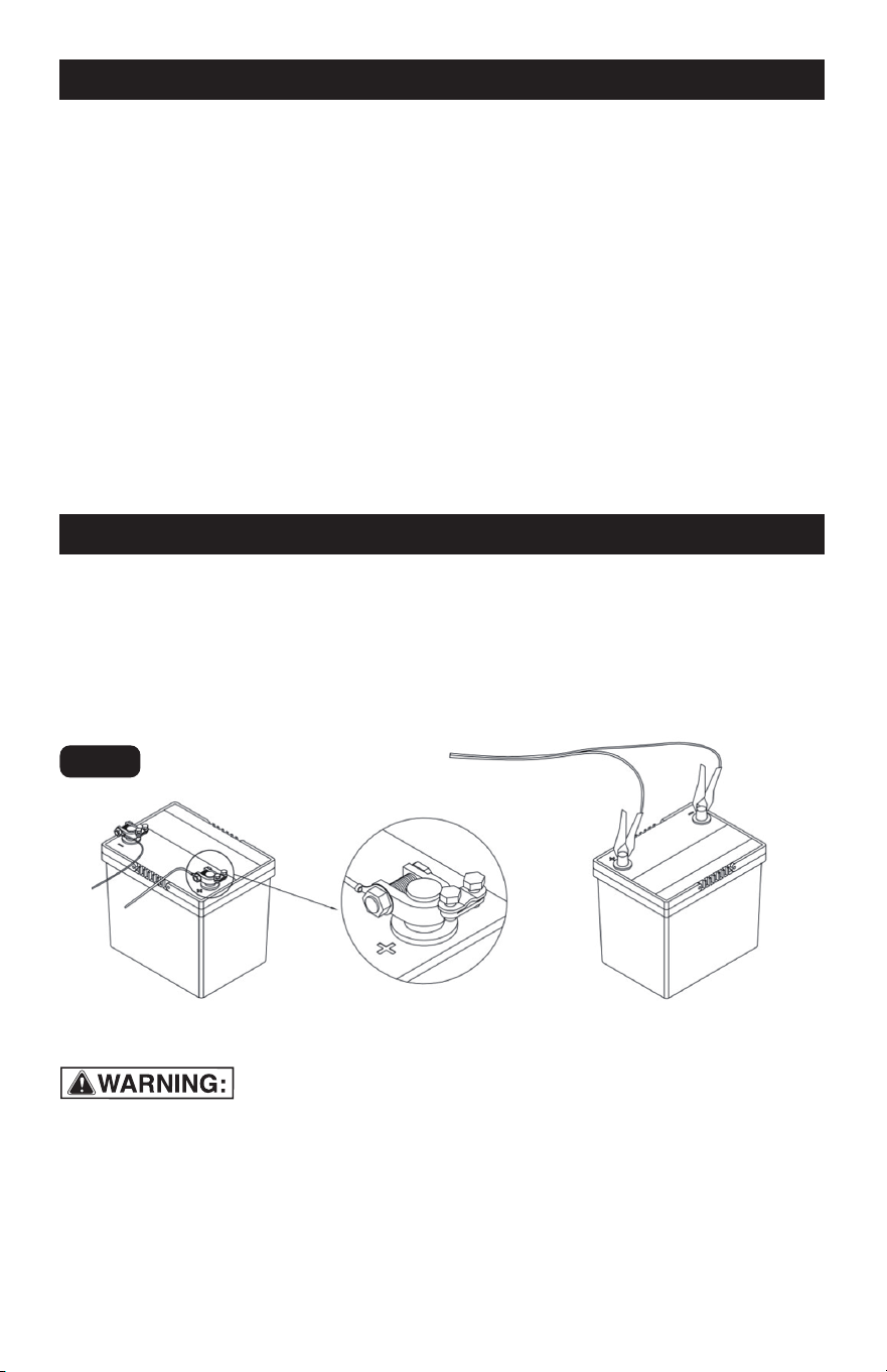
4.2
4.1
Connect and disconnect DC output
clips only after disconnecting
Quick-Connector.
Connect the red clip on connector or
ring terminal connector to the
POSITIVE (POS, P, +) post of the
a.
Position cables to reduce risk of
damage by hood, door, or moving
engine part.
4.3
battery, and connect the black clip on
connector or ring terminal connector
to the NEGATIVE (NEG, N, -) terminal
post of the battery.
Connect the terminals to the battery as
shown in figures (a) and (b).
4. DC CONNECTION PRECAUTIONS
FOLLOW THESE STEPS
A SPARK NEAR BATTERY MAY CAUSE
BATTERY EXPLOSION.
TO REDUCE RISK OF A SPARK NEAR
BATTERY:
b.
c.
d.
Stay clear of fan blades, belts, pulleys,
and other parts that can cause injury to
persons.
Check polarity of battery connectors.
POSITIVE (POS, P, +) battery connec-
tor usually has larger diameter than
NEGATIVE (NEG, N, –) post.
Disconnect Quick-Connector.
Fig. 1

Page 8
5. SPECIFICATION
6. CONNECTION
To permanently attach the Ring Termi-
nal Connector to the battery, bolt
POSITIVE (RED) ring terminal to
POSITIVE (POS, P, +) post of battery.
Bolt NEGATIVE (BLACK) Ring Terminal
Connector to NEGATIVE (NEG, N, –)
post of battery.
To temporarily attach the Clip Connec-
tor to the battery, connect POSITIVE
(RED) Clip Connector to POSITIVE (POS,
P, +) post of battery. Connect NEGATIVE
e
.
Place Float Charger within 3 feet of
battery. Disconnect the Quick-Connec-
tors from each other.
6
.1
f
.
(BLACK) Clip Connector to NEGATIVE
(NEG, N, –) post of battery. Do not
connect Clip Connector to carburetor,
fuel lines, or sheet-metal body parts. Do
not leave Clip Connectors attached
indefinitely.
When disconnecting the charger,
disconnect the quick connector and
then remove the clip type connector
from the battery terminal.
g.
Select the proper Connector.
To permanently attach the Ring Termi-
nal Connector to the battery:
a. Bolt POSITIVE (RED) Ring Terminal
Connector to POSITIVE (POS, P, +) post
of battery.
b. Bolt NEGATIVE (BLACK) Ring Termi-
nal Connector to NEGATIVE (NEG, N, –)
post of battery.
To temporarily attach the Clip Connec-
tor to the battery,
a. Connect POSITIVE (RED) Clip
Connector to POSITIVE (POS, P, +) post
of battery.
b. Connect NEGATIVE (BLACK) Clip
6.2
6.3
6.4
Input Voltage AC 120Vac, 60Hz, 0.55A
Type of Batteries 6V Lead Acid Battery 12V Lead Acid Battery
Charging Voltage 7.5V DC 14.5V DC
Starting Voltage ≥3.5V
Output Power 29W (Max)
Charging Current
Efficiency
Battery Capacity
Cable Length
Overvoltage protection
Over Temperature Protection
reverse polarity protection
Working Temperature
2.0Amp (Max)
82% Approx
5-120AH, Maintains All Battery Sizes
6 FT.
Yes
Yes
Yes
32 °F~104 °F
A SPARK NEAR BATTERY MAY CAUSE
BATTERY EXPLOSION. TO REDUCE RISK
OF A SPARK NEAR BATTERY follow these
instructions exactly.
TO PREVENT SERIOUS INJURY:
Wear splash-resistant safety goggles and
heavy-duty rubber work gloves whenever
connecting, disconnecting, or working
near battery. Battery acid can cause
permanent blindness.
Page 9
7. LED DISPLAY STATUS
8. OPERATION INSTRUCTIONS
TO PREVENT SHORT CIRCUIT AND FIRE:
Do not leave Clips attached indefinitely.
Do not connect Connector to carburetor,
fuel lines, or sheet-metal body parts.
Connector to NEGATIVE (NEG, N, –) post of
battery.
After disconnecting the cable, the power
indicator light red LED remains on.
Join the Connector’s Quick-Connector
plug with charger.
If cables are connected improperly,
disconnect the Quick-Connector plugs,
correct the battery connections, and
re-connect the Quick-Connector plugs.
6.5
6.6
" Power " key once to exit the charging.
Press the "Power" key again to cycle
the charging voltage.
"Power" button: select charging
voltage, start charging and stop
charging.
8.4
Press the "Power" key to cycle to select
the charging voltage.
Select the correct charging voltage and
automatically start charging after 5
seconds without pressing the button.
During the charging process, press the
8.1
8.2
8.3
LED Indicator Status Working Condition
Red LED Solid
Charger Standby (Battery Unconnected State) / Bad Batter
y
Red LED Flashing
Battery Reversed Connection / Charging Fault State /
Overvoltage Protection
Orange LED Flashing Low voltage and Pulse Repair Status
Blue LED Solid 6V Battery Charging Paused
Blue LED Flashing 6V Battery Charging
Blue LED Respiratory State 6V Battery Fully Charged
Green LED Solid 12V Battery Charging Paused
Green LED Flashing 12V Battery Charging
Green LED Respiratory State 12V Battery Fully Charged
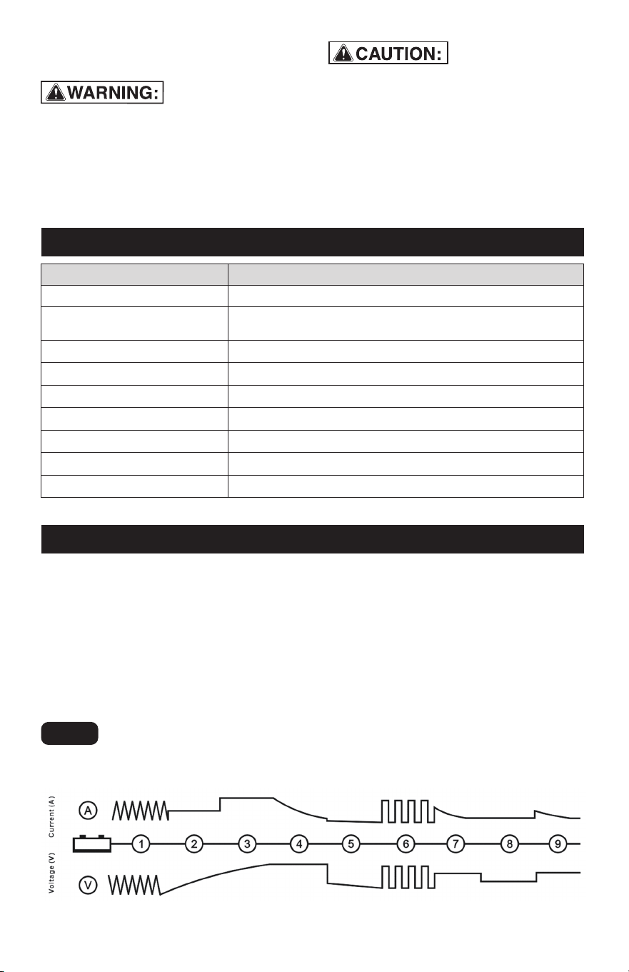
Desulphation
1/2 Constant
Current
Constant
Current
Constant
Voltage
Analysis Recond
Trickle
charge
Diagnosis Maintenanc
e
CHARGING PROCESS
Fig. 2

Page 10
Pulse/Desulphation: Detects sulfurated
batteries, then removes sulfuret from the
lead plates of the battery by Pulsing
Current and Voltage.
1/2 Constant Current: Charging battery to
25% capacity by 1/2 Current.
Constant Current: Charging battery to
50% capacity by max Current.
Constant Voltage: Charging battery to
75% capacity by Constant Voltage.
Analysis: Analysing power capacity. If the
battery can't store power then it should be
replaced.
Recond: Restores power capacity in a
stratified battery to sustain ultimate battery
life.
Trickle charge: Charge the battery to 100%
capacity with a constant voltage and small
current, and maintain the battery voltage at
its maximum level.
Diagnosis: To check if battery has been
fully charged.
Maintenance: The battery has been fully
charged.
The charger automatically detects the
battery status and adjusts the charging
process.
9. AFTER USING
blades, and any other moving engine
parts.
• Remove Clip Connector from battery.
Wipe the Charger with a clean, dry cloth
and store indoors out of reach of
children.
9.4
Disconnect the Quick-Connectors from
each other.
Unplug the charger.
Depending on the Connector in use, either:
• Stow Ring Terminal Connector safely
next to battery. Keep clear of belts,
9.1
BEFORE EACH USE, inspect the
10.1
9.2
9.3
10. MAINTENANCE
general condition of the charger.
Check for:
• loose hardware,
• cracked or broken parts,
• damaged electrical wiring or cable
insulation, and
• any other condition that may affect its
safe operation.
AFTER USE, wipe external surfaces of
the tool with clean cloth.
If the supply cord of this charger is
damaged, it must be replaced only by a
qualified service technician. DO NOT
OPEN CHARGER HOUSING, NO
USER-SERVICEABLE PARTS INSIDE.
10.2
10.3
Procedures not specifically explained in
this manual must be performed only by a
qualified technician.
TO PREVENT SERIOUS INJURY: Unplug
the charger, disconnect any battery, and
allow charger to cool completely before
performing any inspection, maintenance, or
cleaning procedures.
TO PREVENT SERIOUS INJURY FROM
TOOL FAILURE:
Do not use damaged equipment. If abnor-
mal noise or vibration occurs, have the
problem corrected before further use.
Page 11
12. TROUBLE SHOOTING
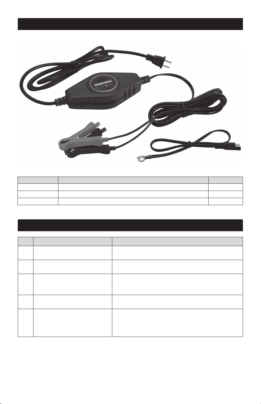
11. PARTS LIST
Part
Description
Qty
1
Charger
1
2
Ring Terminal Connector
1
3
Clip Connector
1
No. Problem Troubleshooting
1
No reaction when connecting
power supply
2
.
3
4
5
Red LED remains on
Red LED flashing
Orange LED flashing
The charging voltage cannot
be selected or the switch
button is insensitive.
Check whether the charger and socket are tightly
plugged and in good contact.
Check if the battery is connected or if the battery
voltage is too low.
Check whether the battery terminal connection is
correct.
Check if the battery voltage is correct.
Check if the connected battery is 6V.
Is the 12V battery voltage too low.
This could be a potentially wrong choice.
Turn off the power and turn it back on again.
If the problem persists, the switch may be damaged,
contact your local vendor.
1
3
2

NOTES
Page 12

Page 13
NOTES

Page 14
NOTES

6/12V 2A High-frequency Charger
WARRANTY
90-DAY MONEY BACK GUARANTEE
This MASTERFORCE™ brand battery charger carries our 90-Day Money Back
Guarantee. If you are not completely satisfied with your MASTERFORCE™
brand product for any reason within ninety (90) days from the date of purchase,
return the item with your original receipt to any MENARDS
®
retail store, and we
will provide you a refund – no questions asked.
3-YEAR LIMITED WARRANTY
This MASTERFORCE™ brand battery charger carries our famous No Hassle
3-Year Limited Warranty to the original purchaser. If, during normal use, this MAS-
TERFORCE™ product breaks or fails due to a defect in material or workmanship
within three (3) years from the date of original purchase, simply bring the item
with the original sales receipt back to your nearest MENARDS
®
retail store. At its
discretion, MASTERFORCE™ agrees to ha
ve the item or any defective part(s)
repaired or replaced with the same or similar MASTERFORCE™ product or part
free of charge, within the stated warranty period, when returned by the original
purchaser with original sales receipt. Not withstanding the foregoing, this limited
warranty does not cover any damage that has resulted from abuse or misuse of
the Merchandise. This warranty: (1) excludes expendable parts including but not
limited to blades, brushes, belts, bits, light bulbs, and/or batteries; (2) shall be
void if this product is used for commercial and/or rental purposes; and (3)
does
not cover any losses, injuries to persons/property or costs. This warranty does
give you specific legal rights and you may have other rights, which vary from
state to state. Be careful, battery chargers are dangerous if improperly used or
maintained. Seller’s employees are not qualified to advise you on the use of this
merchandise. Any oral representation(s) made will not be binding on seller or its
employees. The rights under this limited warranty are to the original purchaser
of the merchandise and may not be transferred to any subsequent owner. This
limited warranty is in
lieu of all warranties, expressed or implied including war-
ranties or merchantability and fitness for a particular purpose. Seller shall not be
liable for any special, incidental, or consequential damages. The sole exclusive
remedy against the seller will be for the replacement of any defects as provided
herein, as long as the seller is willing or able to replace this product or is willing
to refund the purchase price as provided above. For insurance purposes, seller
is not allowed to demonstrate any of these products for you.
For questions/comments, technical assistance or repair parts—
Please call toll free at: 1-877-898-3958.
Page 15

© 2024 Menard, Inc., Eau Claire, WI 54703
01/2024