•IAMAN®
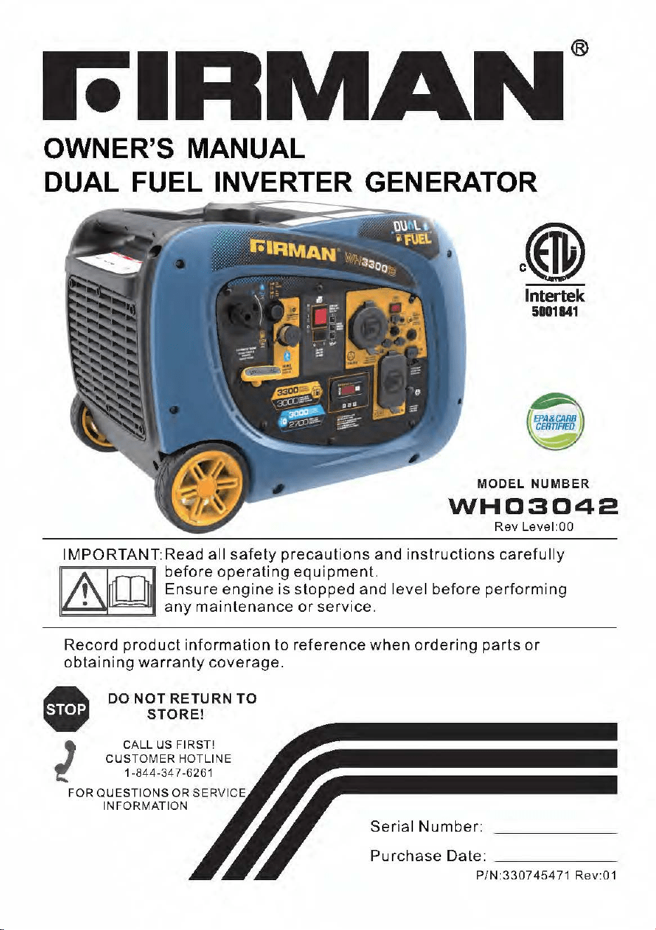
OWNER'S MANUAL
DUAL FUEL INVERTER GENERATOR
lntertek
5001841
MODEL
NUMBER
WH0:3042
Rev
Level:00
IMPORTANT:Read all
safety
precautions
and
instructions
carefully
before
operating
equipment.
Ensure_engine
is
steppe~
and
level
before
performing
any
maintenance
or
service.
Record
product
information
to
reference
when
ordering
parts
or
obtaining
warranty
coverage
.
•
l
DO
NOT
RETURN
TO
STORE!
CALL
US FIRST!
CUSTOMER HOTLINE
1-844-34 7-6261
FOR QUESTIONS OR SERVICE
INFORMATION
Serial
Number:
Purchase
Date:
_____
_
P/N:330745471
Rev:01
Tabla
of
contents
Introduction.
........
.
....
. . . .
........
1
Safety Precautions .
Unpacking The Generator.
Parts Included.
Controls and Features.
Generator.
Control Panel.
.
..
2
.
..
7
.
..
7
. . 8
. . . . . . 8
. . . . . . . . . . . . . 9
Maintenance
And
Storage
.
....
. . . . .
....
27
Maintenance
Schedule
Engine
Maintenance
..
Change
Engine
Oil
..
Air
Filter
Maintenance
.
Spark
Plug
Maintenance
.
..
27
. 28
. . . . . .
...
28
...
28
.
....
29
Inspect
Muffler
and
Spark
Arrester
...
30
Battery Cable Connection. .
...
10
Generator
Maintenance
..............
30
Regulator Cover Installation. . . . . 10
Battery
Replacement
...............
30
Specifications. . . .
...........
. . .
...
11
Charging
The
Generator
Battery.
31
Add
Engine Oil
......
.. . . . . . . . . . . .
....
12
Service
and
Storage
.................
32
Low Oil
Shutdown..
. .12
Trouble
Shooting
.....................
33
Add
Fuel.
. .13 Parts
Diagram
and
Parts
List.
. .
..
34
Operation at High Altitude
....
. . . .
...
16
Grounding
...........................
17
Connecting
to
a
Building's
Electrical
Generator
Parts
Diagram
.
Engine
Parts Diagram
Parts
List
. 34
.......
35
...
36
System
.............................
17
Service
Information
.....
. . .
..
.
..
.. .
...
38
Operation . .
.......
18
Warranty.
. . .
...
. . . . . . .
..
. . .
....
38
Generator Location
...
.
...
. . . . . . .
....
18
Surge Protection
.....................
18
Starting the Generator(Recoil Start-Gas }.19
Starting the Generator(Recoil Start-LPG}.19
Starting the Generator (Electric Start-Gas}.21
Starting the Generator (Electric Start-LPG}.22
Connecting Electrical Loads . .
.....
23
Economy Control Switch. . .
..
24
12V
DC Outlet (Battery Charger)
.......
24
Stopping the Engine
.................
25
Low Oil Shutdown
Do
Not
Overload Generator .
Parallel Operation.
English
...
25
....
25
.
..
26
Custom
er Se
rvic
e 1 -8
44-FIRMAN
1
INTRODUCTION
Thank
you
for
purchasing a FIRMAN generator.
This
manual
contains
safety
information
to
make
you
aware
of
the
hazards
and
risks
associated
with
generator
products
and
how
to
avoid
them.
This
generator
is
designed
and
intended
only
for
supplying
electrical
power
for
operating
compatible
electrical
lighting,
appliances,
tools
and
motor
loads,
and
is
not
intended
for
any
other
purpose.
It
is
important
that
you
read
and
understand
these
instructions
thoroughly
before
attempting
to
start
or
operate
this
equipment.
Save
these
original
instructions
for
future
reference.
This manual covers
operation
and maintenance
of
the
FIRMAN generators.
All
information
in this
publication
is
based
on
the
latest
production
information
available
at
the
time
of
approval
for
printing.
The manufacturer reserves
the
rig
ht
to
change,
alter
or
other
wise
improve
the
generator
and this
documentation
at
any
time
without
prior
change.
Important
Safetv
Information
The
manufacturer
cannot
possibly
anticipate
every
possible
circumstance
that
might
involve
a
hazard.
The
warnings
in
this
manual
and
the
tags
and
decals
affixed
to
the
unit
are
therefore
not
al I-
inclusive.
If
you
use a p
raced
ure,
work
method
or
operating
technique
that
the
manufacturer
does
nots
pee
ifica
I
ly
recommend
you
must
satisfy
you
rs
elf
that
it
is
safe
for
you
and
others.
You
must
also
make
sure
that
the
procedure
work
method
or
operating
technique
that
you
choose
does
not
render
the
generator
unsafe.
English
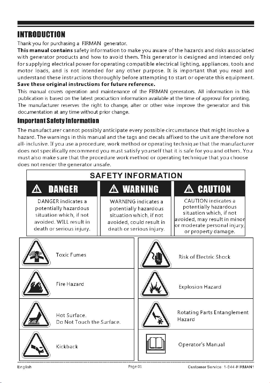
DANGER
indicates
a
potentially
hazardous
situation
which,
if
not
avoided.
WILL
result
in
death
or
serious
injury.
Toxic
Fumes
Fire
Hazard
Hot
Surface.
WARNING
indicates
a
potentially
hazardous
situation
which,
if
not
avoided,
could
result
in
death
or
serious
injury.
Do
Not
Touch
the
Surface.
Kickback
Page 01
CAUTION
indicates
a
potentially
hazardous
situation
which,
if
not
avoided,
may
result
in
mino
or
moderate
personal
injury,
or
property
damage.
Risk
of
Electric
Shock
Explosion
Hazard
Rotating
Parts
Entanglement
Hazard
Operator's
Manual
Customer
Service
1
-844-FIRMAN
1
SAFOY
PRECAUTIONS
A DANGER
Ualng
■
g
■n■
l"IIIDr
ln-r
■
CAN
KILL
YOU
IN
MINUTES.
o-r
■
tor
uh
■
u
■
t
contain
■ o■
rbon
rnonCllllde.
lhl
■
I
■
■
po....,.you
..
nnot-w-
■
U.
@~
f)
~
NEVER
UH
ineide.
horn
■
Only
...
OUTIIDE and
or
oar
■
ae,
EVEN
IF-
..
far
...-y
from
wind.,..,
and
wind-
ar
■
open.
door
■,
and
wenta.
Avoid
other
g ■
n
■
r
■
tor
hpards.
READ MANUAL BEFORE USE.
A
WARNING
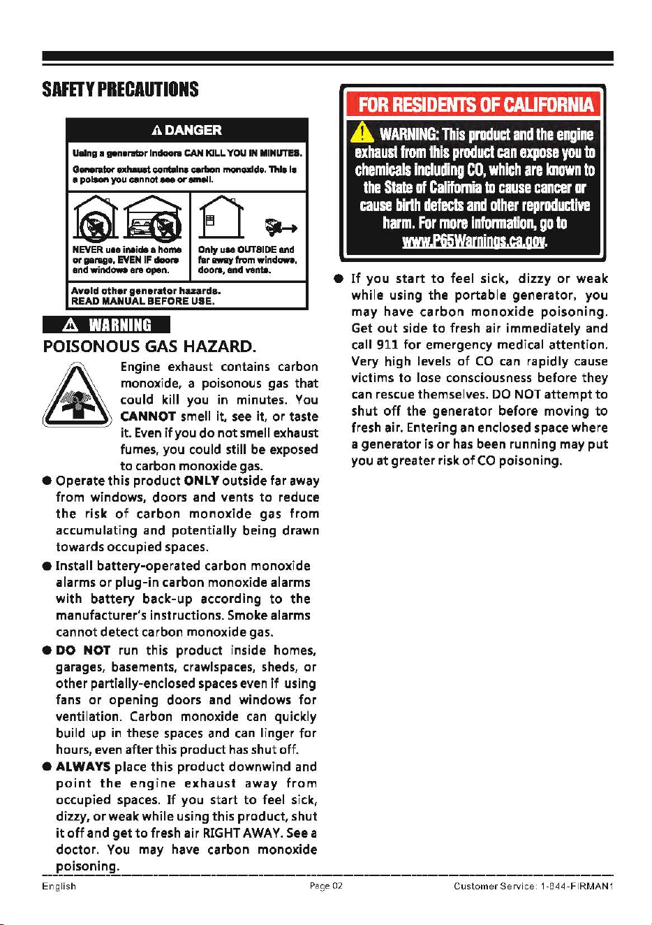
POISONOUS GAS HAZARD.
& Eog;"'
o,hau,t
coota;o,
mboo
monoxide, a poisonous
gas
that
could kill you in minutes.
You
CANNOT smell it.
see
it.
or
taste
it.
Even
if
you
do
not
smell exhaust
fumes, you could still be exposed
to
carbon monoxide
gas.
• Operate this product ONLY outside far away
from windows, doors and vents
to
reduce
the
risk
of
carbon
monoxide
gas
from
accumulating and potentially being drawn
towards occupied spaces.
• Install battery-operated carbon monoxide
alarms
or
plug-in carbon monoxide alarms
with battery back-up according
to
the
manufacturer's instructions. Smoke alarms
cannot detect carbon monoxide gas.
• DO NOT run this product inside homes,
garages, basements, crawlspaces,
sheds,
or
other partially-enclosed
spaces
even
if
using
fans
or
opening doors and windows
for
ventilation. Carbon monoxide
can
quickly
build up
in
these
spaces
and
can
linger
for
hours,
even
after this product
has
shut off.
• ALWAYS place this product downwind and
point
the
engine
exhaust
away
from
occupied spaces.
If
you start
to
feel sick,
dizzy,
or
weak while using this product, shut
it
off
and
get to
fresh air
RIGHT
AWAY.
See
a
doctor. You may have carbon monoxide
poisoning.
•
If
you
start
to
feel sick,
dizzy
or
weak
while using
the
portable generator, you
may have
carbon
monoxide
poisoning.
Get
out
side
to
fresh air immediately and
call 911
for
emergency medical attention.
Very high levels
of
CO
can
rapidly cause
victims
to
lose consciousness before they
can
rescue themselves.
DO
NOT
attempt
to
shut
off
the
generator before moving
to
fresh air. Entering an enclosed space where
a generator
is
or
has
been running may
put
you
at
greater risk
of
CO
poisoning.
English
Page 02
Customer
Se
rvic
e
1-
8
44-FIRMAN
1
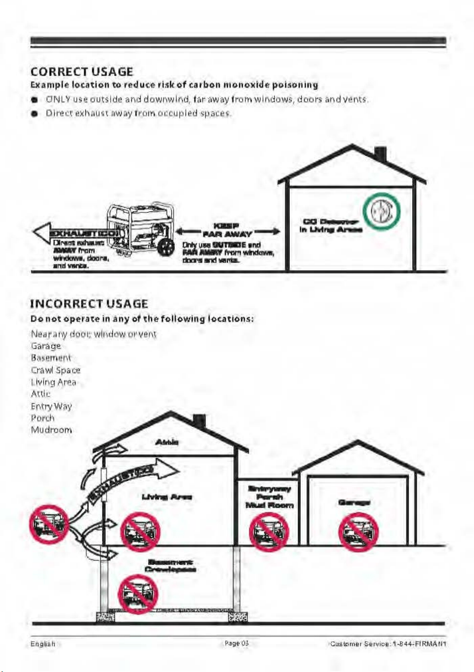
CORRECT USAGE
Example location to redu•
c.e
risk of carb
on
1t1on
o
11id
e
pc>isoning
•
DNL
Y u
se
outside
ar1d
dow
" wlr1d,
iar
away
fr
om wlMJows, doors
ar1d
v~"
ts
,
• Dlr
e~
t exhM1~1 ~WDY 1m m o~cupled spa,e~
INCORRE
CT USAGE
Do
not
operat<!
in
a
ny
of
tlie
following
l
ocations
:
N
ea
r~
11
y ~i
oo
1:. w
ll
,d
ow
cw
veM
Garage
B
~~
~1r\u
f'1\
Crawl
Space
1 lvlr
1g
Area
A
nk
E
nt
1y W
,y
Po~c
l\
Mu
dr
oom
Engl/$h
,,
..
I •
Page
OS
(@
m w
lnUwl,_..,_
Cu
S;
tp
rne1
Se
rvice:
1.S4
4-FI
RM
A
u,
A
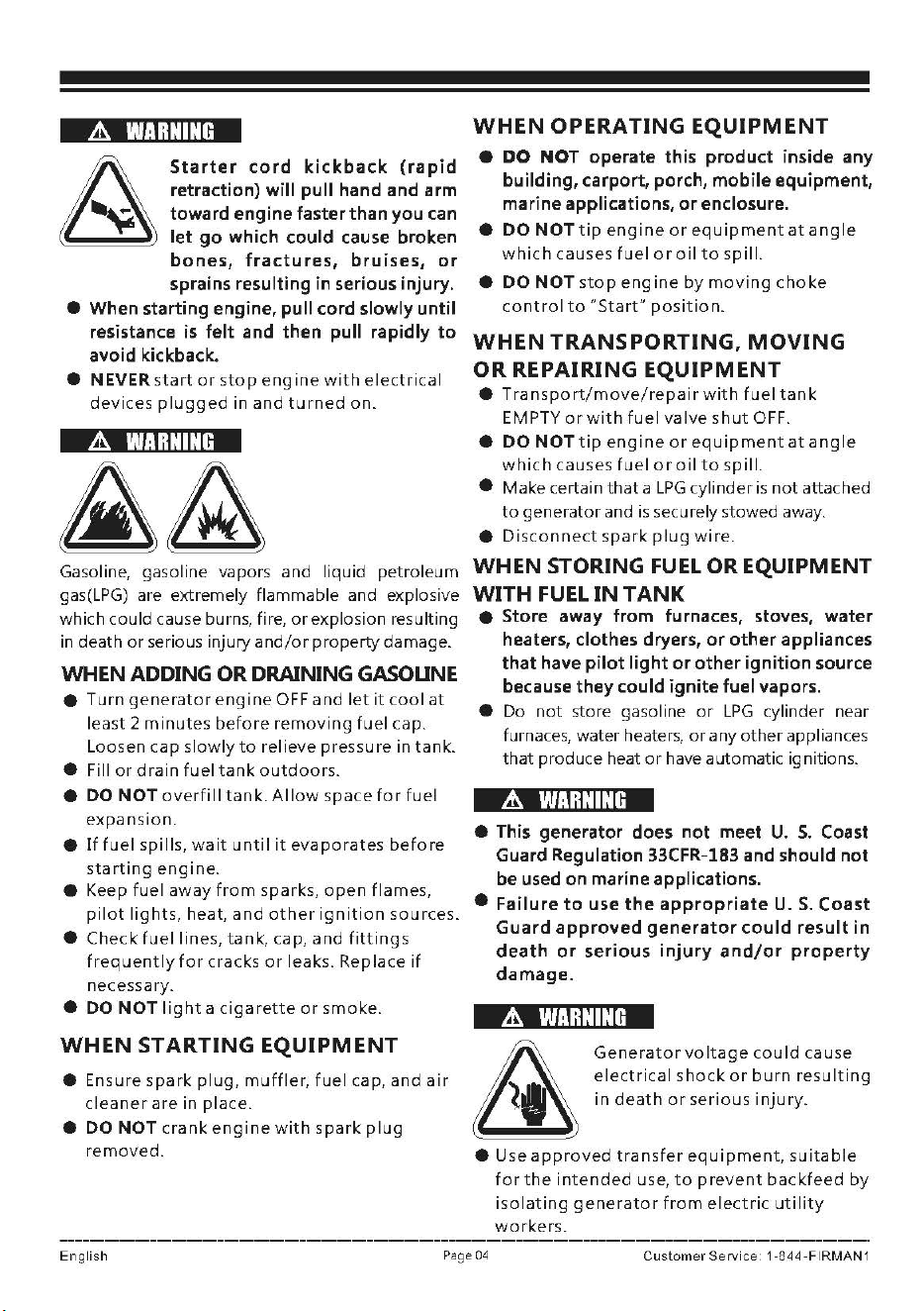
WARNING
Starter
cord
kickback
(rapid
retraction) will pull hand and arm
toward engine faster than you can
let
go
which could cause broken
bones,
fractures,
bruises,
or
sprains resulting in serious injury.
• When starting engine, pull cord slowly until
resistance
is
felt and then pull rapidly
to
avoid kickback.
•
NEVER
start
or
stop
engine
with
electrical
devices
plugged
in
and
turned
on.
&
WARNING
Gasoline, gasoline vapors
and
liquid petroleum
gas(LPG) are extremely flammable and explosive
which could cause burns, fire,
or
explosion resulting
in death
or
serious injury
and/or
property
damage.
WHEN
ADDING
OR
DRAINING
GASOLINE
•
Turn
generator
engine
OFF
and
let
it
cool
at
least 2
minutes
before
removing
fuel cap.
Loosen
cap
slowly
to
relieve pressure in
tank.
• Fill
or
drain
fuel
tank
outdoors.
• DO
NOT
overfill
tank.
Allow
space
for
fuel
expansion.
•
If
fuel
spills,
wait
until
it
evaporates
before
starting
engine.
• Keep
fuel
away
from
sparks,
open
flames,
pilot
lights,
heat,
and
other
ignition
sources.
•
Check
fuel
lines,
tank,
cap,
and
fittings
frequently
for
cracks
or
leaks. Replace
if
necessary.
• DO
NOT
light
a
cigarette
or
smoke.
WHEN STARTING EQUIPMENT
• Ensure
spark
plug,
muffler,
fuel
cap,
and
air
cleaner
are in
place.
•
DO
NOT
crank
engine
with
spark
plug
removed.
WHEN OPERATING EQUIPMENT
•
DO
NOT
operate this product inside any
building, carport, porch, mobile equipment,
marine applications,
or
enclosure.
•
DO
NOT
tip
engine
or
equipment
at
angle
which
causes
fuel
or
oil
to
spill.
•
DO
NOT
stop
engine
by
moving
choke
control
to
"Start"
position.
WHEN TRANSPORTING, MOVING
OR REPAIRING EQUIPMENT
•
Transport/move/repair
with
fuel
tank
EMPTY
or
with
fuel
valve
shut
OFF.
•
DO
NOT
tip
engine
or
equipment
at
angle
which
causes
fuel
or
oil
to
spill.
• Make certain
that
a
LPG
cylinder
is
not
attached
to
generator and
is
securely stowed away.
•
Disconnect
spark
plug
wire.
WHEN
STORING
FUEL
OR
EQUIPMENT
WITH
FUEL
IN
TANK
• Store away from furnaces, stoves, water
heaters, clothes dryers,
or
other
appliances
that
have pilot light
or
other ignition source
because they could ignite fuel vapors.
• Do
not
store gasoline
or
LPG
cylinder near
furnaces, water heaters,
or
any
other
appliances
that
produce heat
or
have automatic ignitions.
A
WARNING
• This generator does not meet
U.
5.
Coast
Guard Regulation 33CFR-183 and should not
be used on marine applications.
• Failure
to
use
the
appropriate
U.S.
Coast
Guard
approved
generator
could result in
death
or
serious
injury
and/or
property
damage.
&
WARNING
&
Generator
voltage
could
cause
electrical
shock
or
burn
resulting
in
death
or
serious
injury.
• Use
approved
transfer
equipment,
suitable
for
the
intended
use,
to
prevent
backfeed
by
isolating
generator
from
electric
utility
workers.
English
Page
04
Customer
Service
1
·844
·FIRMAN
1
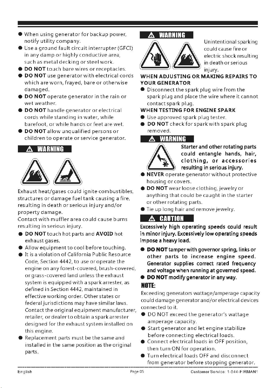
•
When
using
generator
for
backup
power,
notify
utility
company.
• Use a
ground
fault
circuit
interrupter
(GFCI)
in
any
damp
or
highly
conductive
area,
such
as
metal
decking
or
steel
work.
•
DO
NOT
touch
bare
wires
or
receptacles.
•
DO
NOT
use
generator
with
electrical
cords
which
are
worn,
frayed,
bare
or
otherwise
damaged.
•
DO
NOT
operate
generator
in
the
rain
or
wet
weather.
•
DO
NOT
handle
generator
or
electrical
cords
while
standing
in
water,
while
barefoot,
or
while
hands
or
feet
are
wet.
•
DO
NOT
allow
unqualified
persons
or
children
to
operate
or
service
generator.
A
WARNING
Exhaust
heat/gases
could
ignite
combustibles,
structures
or
damage
fuel
tank
causing
a
fire,
resulting
in
death
or
serious
injury
and/or
property
damage.
Contact
with
muffler
area
could
cause
burns
resulting
in
serious
injury.
e
DO
NOT
touch
hot
parts
and
AVOID
hot
exhaust
gases.
•
Allow
equipment
to
cool
before
touching.
•
It
is
a
violation
of
California
Public
Resource
Code,
Section
4442,
to
use
or
operate
the
engine
on
any
forest-covered,
brush-covered,
or
grass-covered
land
unless
the
exhaust
system
is
equipped
with
a
spark
arrester,
as
defined
in
Section
4442,
maintained
in
effective
working
order.
Other
states
or
federal
jurisdictions
may
have
similar
laws.
Contact
the
original
equipment
manufacturer,
retailer,
or
dealer
to
obtain
a
spark
arrester
designed
for
the
exhaust
system
installed
on
this
engine.
•
Replacement
parts
must
be
the
same
and
installed
in
the
same
position
as
the
original
parts.
&
WARNING
&
Unintentional
sparking
£
could
cause
fire
or
electric
shock
resulting
1n
death
or
serious
injury.
WHEN
ADJUSTING
OR
MAKING
REPAIRS
TO
YOUR
GENERATOR
•
Disconnect
the
spark
plug
wire
from
the
spark
plug
and
place
the
wire
where
it
cannot
contact
spark
plug.
WHEN
TESTING
FOR
ENGINE
SPARK
• Use
approved
spark
plug
tester.
•
DO
NOTcheckforsparkwith
spark
plug
removed.
A
WARNING
Starter
and
other rotating
parts
could
entangle
hands,
hair,
clothing,
or
accessories
resulting
in
serious
injury.
• NEVER
operate
generator
without
protective
housing
or
covers.
•
DO
NOTwearlooseclothing,jewelryor
anything
that
could
be
caught
in
the
starter
or
other
rotating
parts.
• Tie
up
long
hair
and
remove
jewelry.
A
CAUTION
Excessively
high
operating
speeds
could
result
in
minor
injury.
Excessively
low
operating
speeds
impose
a
heavy
load.
•
DO
NOT
tamper
with
governor
spring,
links
or
other parts to increase engine speed.
Generator
supplies
correct
rated
frequency
and
voltage
when
running
at
governed
speed.
•
DO
NOT
modify
generator
in
anyway.
NOTE:
Exceeding
generators
wattage/amperage
capacity
could
damage
generator
and/or
electrical devices
connected
to
it.
•
DO
NOT
exceed
the
generator's
wattage
amperage
capacity.
•
Start
generator
and
let
engine
stabilize
before
connecting
electrical
loads
.
•
Connect
electrical
loads
in OFF
position,
then
turn
ON
for
operation.
•
Turn
electrical
loads
OFF
and
disconnect
from
generator
before
stopping
generator.
English
Page
05
Customer
Service
1
-844-FIRMAN
1
NOTI:
Im
proper
treatment
of
generator
could
damage
it
and
shorten
its
life.
• Use
generator
only
for
intended
uses.
•
If
you
have
questions
about
intended
use,
ask
dealer
or
contact
local
service
center.
•
Operate
generator
only
on
level
surf
aces.
•
DO
NOT
expose
generator
to
excessive
moisture,
dust,
dirt,
or
corrosive
vapors.
• DO
NOT
insert
any
objects
through
cooling
slots.
•
If
connected
devices
overheat,
turn
them
off
and
disconnect
them
from
generator.
•Shutoff
generator
if:
-Electrical
output
is
lost.
-Equipment
sparks,
s
makes,
or
emits
flames.
-Unit
vibrates
excessively.
A
WARNING
Medical
and
Life
Support
Uses.
•
In
case
of
emergency,
call
911
immediately.
• NEVER use
this
product
to
power
life
support
devices
or
life
support
appliances.
• NEVER
use
this
product
to
power
medical
devices
or
medical
appliances.
•
Info
rm
your
electricity
provider
immediately
if
you
or
anyone
in
your
household
depends
on
electrical
equipment
to
live.
•
Info
rm
your
electrical
provider
immediately
if
a loss
of
power
would
cause
you
or
anyone
in
your
household
to
experience
a
medical
emergency.
Fuel
Saletv
Gasoline:
A
DANGER
GASOLINE
AND
GASOLINE VAPORS
ARE
HIGHLY
FLAMMABLE
AND
EXPLOSIVE.
Fire
or
explosion
can cause severe
burns
or
death.
Unintentional
startup
can
result
in
entanglement,
traumatic
amputation
or
laceration.
• Gasoline can cause a fire
or
explosion
if
ignited.
• Gasoline
is
a
liquid
fuel
but
it's vapors can ignite.
• Gasoline
is
a skin
irritant
and needs
to
be cleaned
up
immediately
if
spilled on skin
or
clothes.
•
Gasoline
has a
distinctive
odor,
this
will
help
detect
potential
leaks
quickly.
•
In
any gasoline
fire,
flames should
not
be
extinguished
unless
by
doing
so
the fuel supply
valve
can
be turned
OFF.
This
is
because if a fire
is
extinguished and a supply
of
fuel
is
not
turned
OFF,
then
an
explosion hazard could be created.
• Gasoline expands
or
contracts
with
ambient
temperatures.
Never
fill
the
gasoline
tank
to
full capacity,
as
gasoline needs
room
to
expand
if
temperatures
rise.
Liquid
Petroleum
Gas
(LPG/Propane}:
This
generator
is
dual
fuel
and
capable
of
running
with
both
gasoline
and
Liquid
Petroleum
Gas
(LPG/Propane).
A
DANGER
• Liquid Petroleum
Gas
(LPG)
is
highly
flammable
and explosive. Fire
or
explosion can cause severe
burns
or
death.
•
Do
not
use
or
store
LPG
cylinder
in
a
building,
garage
or
enclosed
area.
• Do
not
check
for
leaks
with
a
lighted
match
or
flame.
•
The
LPG
cylinder
valve
should
be
fully
closed
when
the
generator
is
not
in use
or
is
running
with
gasoline.
•
If
you
smell gas: close
off
the
gas supply.
Make
sure
there
is
no
leak
before
using
the
generator.
.It!.
WARNING
• Device used
for
handling
LPG
must be installed
and used
in
strict conformance with NFPA
58
(Liquefied Petroleum
Gas
Code) and
NFPA
54
(National
Fuel
Gas)
and
all
other
codes, regulations
and manufacturer recommendations.
•
Never
use a gas
container,
LPG
connector
hose,
LPG
cylinder
or
any
other
fuel
item
that
is
damaged
or
appears
damaged.
•
The
LPG
cylinder
valve
should
be
fully
closed
when
the
generator
is
not
in use
or
is
running
with
gasoline.
•
The
regulator/hose
assembly
and
cylinder
valve
must
be
inspected
before
each
use
for
leaks
or
sign
of
damages.
English
Page
06
CustomerService
1-844-FIRMAN1
•
If
you
smell gas: close
off
the
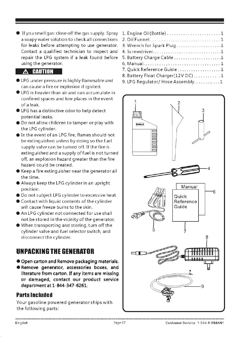
gas supply. Spray 1.
Engine
Oil(Bottle)
.......................
1
a soapy
water
solution
to
check all connections 2.
Oil
Funnel
...............................
1
for
leaks
before
attempting
to
use generator. 3.
Wrench
for
Spark: Plug
..............
.
.....
1
Contact a
qualified
technician
to
inspect and 4.
Screwdriver
...............................
1
repair
the
LPG
system
if
a
leak:
found
before
5.
Battery
Charge
Cable
.....................
1
using
the
generator. 6.
Manual.
.................
. . .
..
...........
1
A
CAUTION
•
LPG
under
pressure is
highly
flammable
and
can cause a
fire
or
explosion
if
ignited.
•
LPG
is
heavier
than
air
and
can
accumulate
in
confined
spaces
and
low
places in
the
event
of
a leak:.
•
LPG
has a
distinctive
odor
to
help
detect
potential
leaks.
•
Do
not
allow
children
to
tamper
or
play
with
the
LPG
cylinder.
• In
the
event
of
an
LPG
fire, flames
should
not
be
extinguished
unless
by
doing
so
the
fuel
supply
valve can
be
turned
off.
If
the
fire
is
extinguished
and
a
supply
of
fuel
is
not
turned
off,
an
explosion
hazard
greater
than
the
fire
hazard cou Id
be
created.
• Keep a
fire
extinguisher
near
the
generator
all
the
time.
• Always keep
the
LPG
cylinder
in an
upright
position.
•
Do
not
subject
LPG
cylinder
to
excessive heat.
•
Contact
with
liquid
contents
of
the
cylinder
will
cause freeze burns
to
the
skin.
•
An
LPG
cylinder
not
connected
for
use shall
not
be
stored
in
the
vicinity
of
the
generator.
•
When
transporting
and
storing
,
turn
off
the
cylinder
valve
and
fuel
selector
switch, and
disconnect
the
cylinder.
UNPACKING
THE
GENERATOR
• Open carton and Remove packaging materials.
• Remove generator, accessories boxes, and
literature from carton.
If
any items are missing
or
damaged, contact
our
product service
department at 1-844-347-6261.
Parts
Included
Your
gasoline
powered
generator
ships
with
the
following
parts:
7. Quick:
Reference
Guide
...................
1
8.
Battery
Float
Charger(12V
DC)
...........
1
9.
LPG
Regulator/
Hose
Assembly
............
1
3
t
Manual
Quick
Reference
Guide
7
6
English
Pa
ge
07
Custom
er Se
rvic
e 1 -8
44-FIRMAN
1
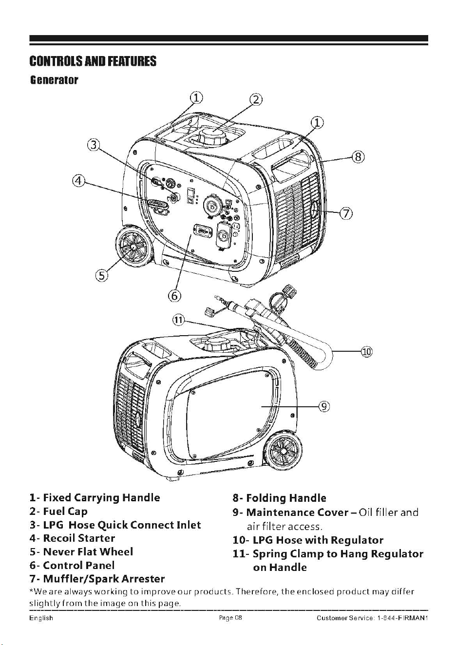
CONTROLS
AND
FEATURES
G11n11ra1or
1-
Fixed Carrying
Handle
2-FuelCap
3-
LPG
Hose Quick Connect
Inlet
4-
Recoil
Starter
5-
Never
Flat
Wheel
6-
Control Panel
7-
Muffler/SparkArrester
8-
Folding
Handle
9-
Maintenance
Cover-Oil
filler
and
air
filter
access.
10-
LPG
Hose
with
Regulator
11-
Spring Clamp
to
Hang
Regulator
on
Handle
*We
are
always
working
to
improve
our
products.
Therefore,
the
enclosed
product
may
differ
slightly
from
the
image
on
this
page.
English
Page
08
Customer
Service
1 -844
·FIRMAN
1
Control
PanBI
e1---lt----------\l
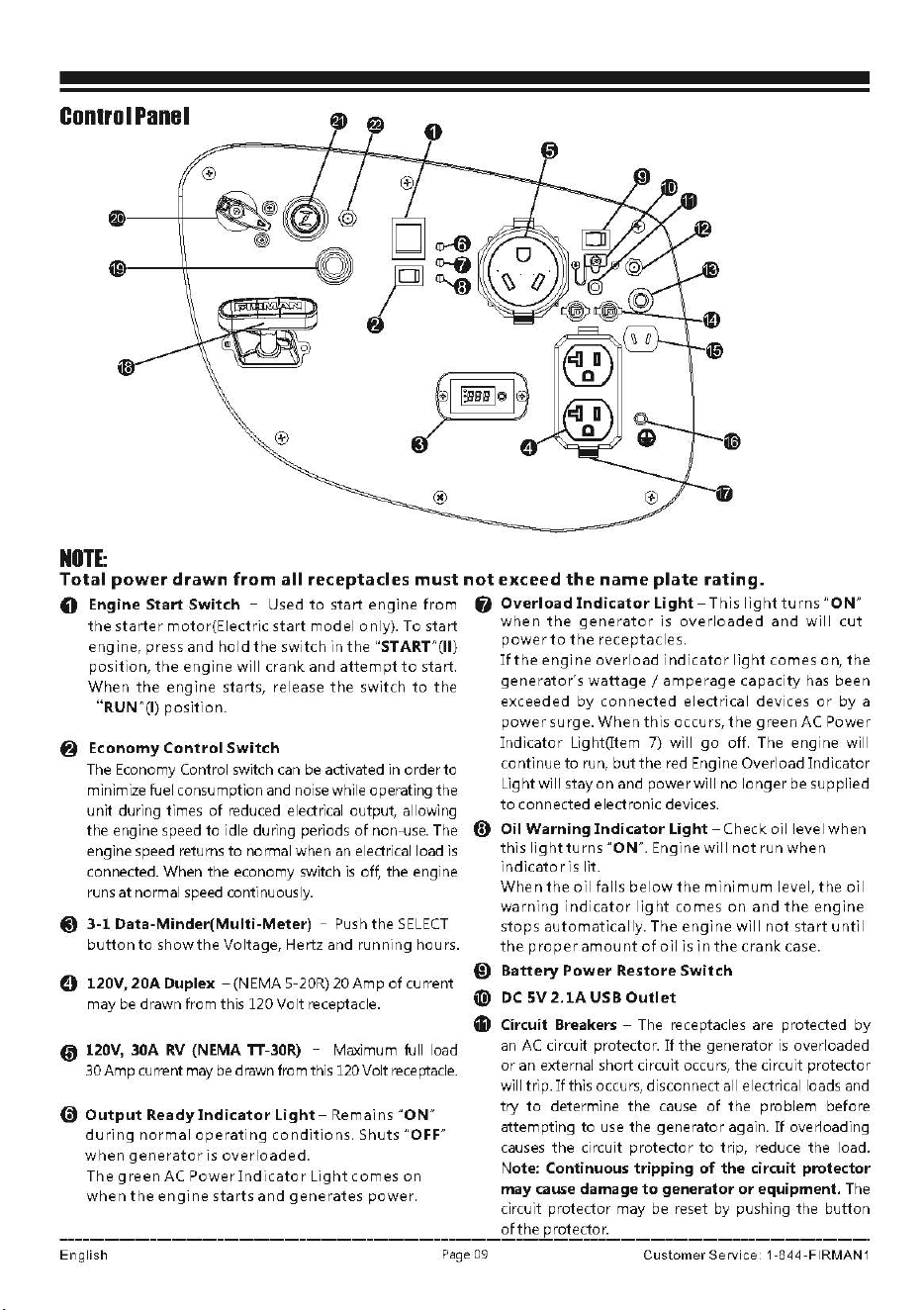
NOTE:
Total
power
drawn
from
all
receptacles
must
not
exceed
the
name
plate
rating.
0 Engine
Start
Switch
- Used
to
start
engine
from
fl
Overload
Indicator
Light
-This
light
turns
"ON"
the
starter
motor(Electric
start
model only). To start
when
the
generator
is
overloaded
and
will
cut
engine, press and
hold
the
switch
in
the
"START"(II)
power
to
the
receptacles.
position,
the
engine
will
crank
and
attempt
to
start.
If
the
engine
overload
indicator
light
comes
on
,
the
When
the
engine
starts, release
the
switch
to
the
generator's
wattage/
amperage capacity has been
"RUN"(I)
position.
exceeded by
connected
electrical devices
or
by a
power
surge.
When
this occurs,
the
green AC Power
8 Economy
Control
Switch
The Economy Control switch
can
be activated in order
to
minimize fuel consumption and noise while operating the
unit during times
of
reduced electrical output, allowing
the
engine speed to idle during periods
of
non-use. The
engine
speed
returns
to
normal when an electrical load
is
connected. When the economy switch
is
off, the engine
runs at normal
speed
continuously.
@
3-1
Data-Minder(Multi-Meter)
-
Push
the
SELECT
button
to
show
the
Voltage, Hertz and running hours.
8
120V,20ADuplex
-(NEMA5-20R)20Ampofcurrent
may
be
drawn from this 120
Vo
lt receptacle.
@ 120V, 30A
RV
(NEMA TT-30R) - Maximum full load
30 Amp current
may
be
drawn from this 120 Volt
receptacle.
G)
Output
Ready
Indicator
Light-
Remai
ns
"ON"
during
normal
operating
conditions.
Shuts "OFF"
when
generator
is
overloaded.
The
green
AC
Power
Ind
icate r
Light
comes
on
when
the
engine
starts
and
generates
power.
Indicator
Lig
ht(ltem 7) will
go
off. The engine will
continue
to
run,
but
the
red
Eng
i
ne
Overload Indicator
Light will stay
on
and power will no longer be supplied
to
connected electronic devices.
(i)
Oil
Warning
Indicator
Light
-Check
oil level
when
this
light
turns
"ON". Engine will
not
run
when
indicato
r is lit.
When
the
oil
falls
below
the
min
imum level, t he
oil
warning
indicator
light
comes
on
and
the
eng
ine
stops
automatically.
The
engine
will
not
start
until
the
proper
amount
of
o ii is
in
the
crank
case.
{!)
Battery
Power
Restore
Switch
(!) DC sv 2.
lA
use
Outlet
GI
Circuit Breakers - The receptacles are protected by
an
AC
circuit protector.
If
t he generator
is
overloaded
or
an external short circuit occurs,
the
circuit protector
will trip.
If
this occurs, disconnect all electrical loads and
try
to
determine
the
cause
of
the
problem before
attempting
to
use the generator again.
If
overloading
causes
the
circuit protector
to
tr
ip, reduce the load.
Note: Continuous tripping
of
the circuit protector
may
cause
damage
to
generator
or
equipment. The
circuit protector may be reset by pushing the button
of
the
protector.
English
Page
09
Customer
Service
1 -844
-FIRMAN
1
@
12V
DC
Battery
Charger
Port
- Plug
the
120
Volt
AC
charger
into
this
port
to
charge
the
generator
battery.
®
DC
Circuit Breaker- The circuit protector may
be
reset
by pushing the button
of
the
protector.
(l
Parallel Operation Outlets - These
outlets
are used
for
connecting
two
FIRMAN
inverter
generators
for
parallel
operation.
A FIRMAN parallel kit(optional
equipment)
is required
for
parallel
operation
.
.(il 12V
DC
outlet
-8.
3 Amp
of
DC
current may
be
drawn
from this receptacle.
Use
this
outlet
to
charge
12V
automotive
type
batteries
ONLY.
See
12V
DC
outlet
(Battery
Charger)
section.
(i)
Ground
Terminal
-Consult
an
electrician
for
local
grounding
regulations.
fl
Outlet
Cover-
Protect
the
receptacles
from
dust
and
debris.
(i) Recoil
Stater
® LPG Hose
Quick
Connect
Inlet
@I
Fuel
Selector
Switch
- Used
to
select
and
turn
on
gas
or
LPG
fuel
source.
GI
Choke
Button
@l
LPG
Regulator
Solenoid
Port
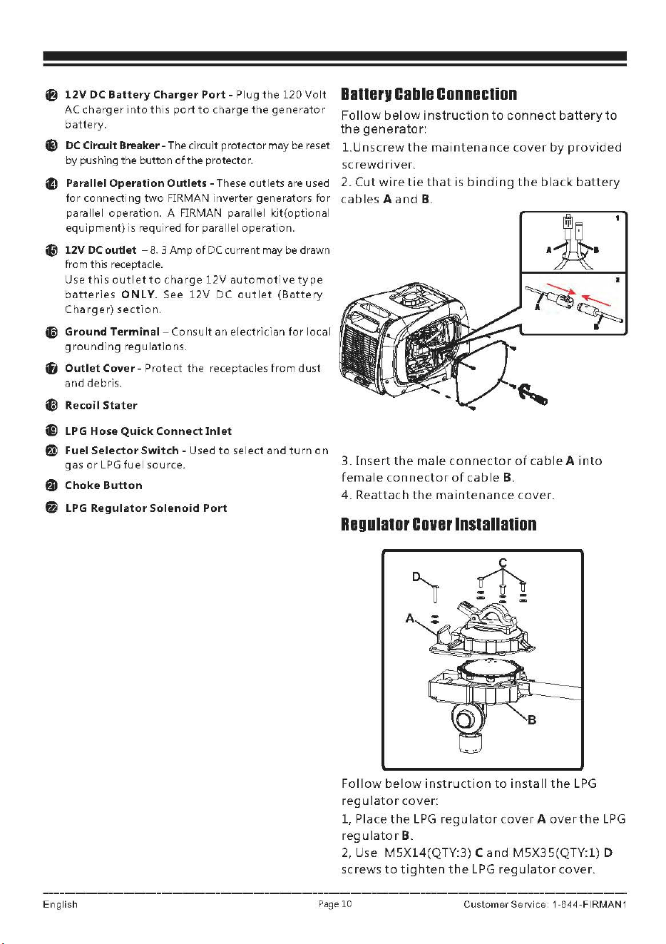
Banerv
Cable
Conneclion
Follow
below
instruction
to
connect
battery
to
the
generator:
l.Unscrew
the
maintenance
cover
by
provided
screwdriver.
2.
Cut
wire
tie
that
is
binding
the
black
battery
cables
A
and
B.
3.
Insert
the
male
connector
of
cable
A
into
female
connector
of
cable
B.
4.
Reattach
the
maintenance
cover.
Regu1a10r
Cover
lnstallalion
Follow
below
instruction
to
install
the
LPG
regulator
cover:
1, Place
the
LPG
regulator
cover
A
over
the
LPG
reg u la
tor
B.
2,
Use
M5Xl4(QTY:3)
C
and
M5X35(QTY:l)
D
screws
to
tighten
the
LPG
regulator
cover.
English
Page
10
Customer
Service
1
-844-FIRMAN
1
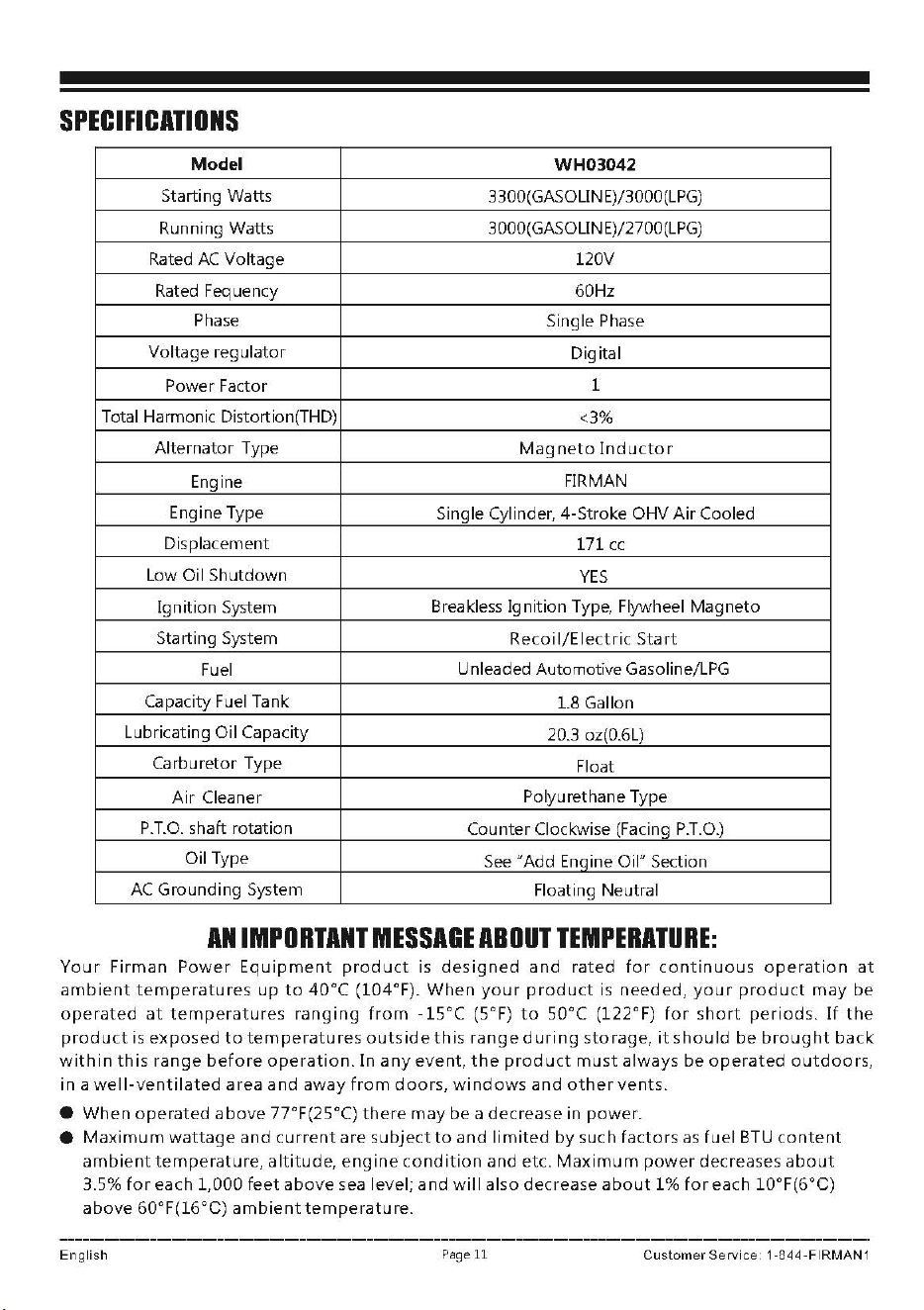
SPECIFICATIONS
Model
WH03042
Starting Watts
3300(GASOLIN E)/3000(LPG)
Running Watts 3000(GASOLIN E)/2700(LPG)
Rated
AC
Voltage 120V
Rated
Feq
uency 60Hz
Phase
Single
Phase
Voltage regulator
Digital
Power Factor
1
Total Harmonic Distortion(THD)
<3%
Alternator Type
Magneto
lnducto
r
Engine
FIRMAN
Engine Type
Single Cylinder, 4-Stroke OHV
Air
Cooled
Displacement
171
cc
Low Oil Shutdown
YES
Ignition System
Breakless Ignition Type, Flywheel Magneto
Starting System Recoi
1/E
lectric
Sta
rt
Fuel
Unleaded Automotive Gasoline/LPG
Capacity
Fuel
Tank
1.8 Gallon
Lubricating Oil Capacity
20.3 oz(0.6L)
Carburetor Type
Float
Air
Cleaner Polyurethane Type
P.T.O.
shaft rotation
Counter Clockwise (Facing
P.T.O.)
Oil Type
See
"Add Enqine Oil" Section
AC
Grounding System
Floating Neutral
AN
IMPORTANT
MESSAGE
ABOUT
TEMPERATURE:
Your
Firman
Power
Equipment
product
is
designed
and
rated
for
continuous
operation
at
ambient
temperatures
up
to
40°C
(104°F).
When
your
product
is
needed,
your
product
may
be
operated
at
temperatures
ranging
from
-15°C
(S°F)
to
S0°C (122°F)
for
short
periods.
If
the
product
is
exposed
to
tern
peratu
res
outside
th
is
ranged
uri
ng
storage,
its
hou
Id
be
brought
back
within
this
range
before
operation.
In
any
event,
the
product
must
always
be
operated
outdoors,
in
a
well-ventilated
area
and
away
from
doors,
windows
and
other
vents.
•
When
operated
above
77°F(25°C)
there
may
be
a decrease in
power.
•
Maximum
wattage
and
current
are
subject
to
and
limited
by
such
factors
as
fuel
BTU
content
ambient
temperature,
altitude,
engine
condition
and
etc.
Maximum
power
decreases
about
3.5%
for
each 1,000
feet
above
sea level;
and
will
also decrease
about
1%
for
each
l0°F(6°C)
above
60°F(l6°C)
ambient
temperature.
English
Page
11
Customer
Service
1
·844
·FIRMAN
1
Add
Engine
Oil
A
CAUTION
DO
NOT
attempt
to
crank
or
start
the
engine
before
it
has
been
properly
filled
with
the
recommended
type
and
amount
of
oil.
Damage
to
the
generator
as
a
result
of
failure
to
follow
these
instructions
will
void
your
warranty.
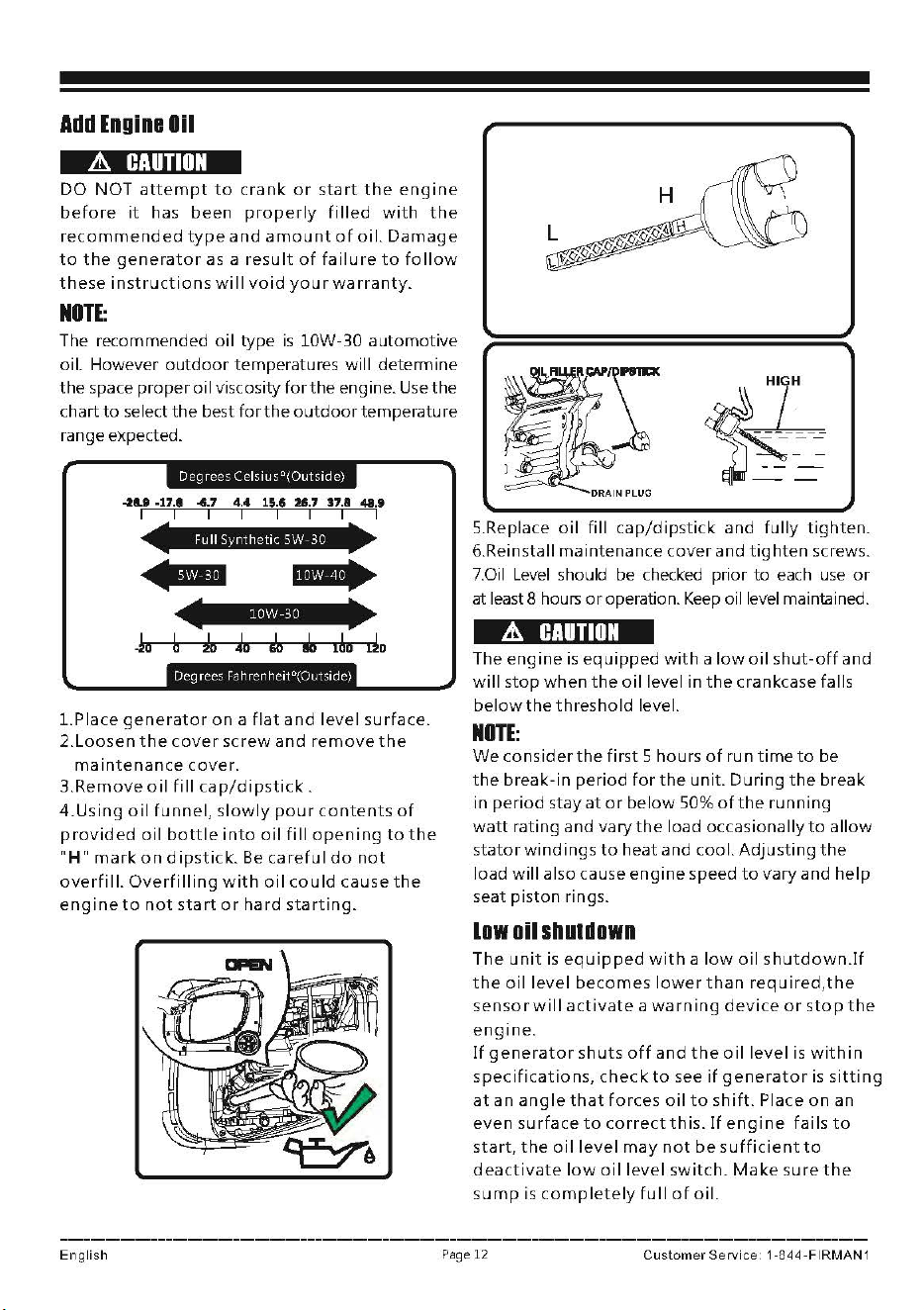
NOTE:
The recommended
oil
type
is
lOW-30
automotive
oil. However
outdoor
temperatures will determine
the space
proper
oil
viscosity
for
the
engine.
Use
the
chart
to
select
the
best
for
the
outdoor
temperature
range expected.
Degrees
Cels1usc,(Outs1de)
~&8
-17,1
"'·'
4.4
15,6 :!li.7 17.1 48.9
I
NIJMll#i
♦
i
I
•
55Mi
114\tt:
►
I
Ill\¥
■
I
Ja
b
~ ~
i/n
Ja
l~D
do
l.Place
generator
on
a
flat
and
level
surface.
2.Loosen
the
cover
screw
and
remove
the
maintenance
cover.
3.Remove
oil
fill
cap/dipstick.
4.Using
oil
funnel,
slowly
pour
contents
of
provided
oil
bottle
into
oil
fill
opening
to
the
"H"
mark
on
dipstick.
Be
ca
refu
I
do
not
overfill.
Overfilling
with
oil
could
cause
the
engine
to
not
start
or
hard
starting.
~\-
~~
DRAIN
PLUG
~
l~~
5.Replace
oil
fill
cap/dipstick
and
fully
tighten.
6.Reinstall maintenance
cover
and
tighten
screws .
7.Oil
Level
should be checked prior
to
each
use
or
at least 8 hou
rs
or
operation.
Keep
oil level maintained.
&.
CAUTION
The
engine
is
equipped
with
a
low
oil
shut-off
and
will
stop
when
the
oil
level in
the
crankcase falls
below
the
threshold
level.
NOTE:
We
consider
the
first
5 hours
of
run
time
to
be
the
break-in
period
for
the
unit.
During
the
break
in
period
stay
at
or
below
50%
of
the
running
watt
rating and
vary
the
load occasionally
to
allow
s
tator
windings
to
heat and cool.
Adjusting
the
load
will
also cause
engine
speed
to
vary
and
help
seat
piston
rings.
Low
oil
shuldown
The
unit
is
equipped
with
a
low
oil
shutdown.If
the
oil
level
becomes
lower
than
requ
ired,the
sensor
will
activate
a
warning
device
or
stop
the
engine.
If
generator
shuts
off
and
the
oil
level
is
within
specifications,
check
to
see
if
generator
is
sitting
at
an
angle
that
forces
oil
to
shift.
Place
on
an
even
surface
to
corre
ct
this.
If
engine
fails
to
start,
the
oil
level
may
not
be
sufficient
to
deactivate
low
oil
level
switch.
Make
sure
the
su
mp
is
completely
full
of
oil.
English
Page
12
Customer
Se
rvic
e 1 -844
-FIRMAN
1
Add
FUBI
I.Gasoline
Fuel
must
meet
these
requirements:
• Clean, fresh,
unleaded
gasoline.
• Use
regular
UNLEADED
gasoline
with
the
generator
engine
with
a
minimum
87
octane
/
87
AKI (91 RON).
For
high
altitude
use, see
"Operation
at
High
Altitude".
•
Do
not
use
gasoline
with
more
than
10%
alcohol
such
as
E85
or
ethanol.
lffl:
Avoid
generator
damage.
Failure
to
follow
Operator
's
Manual
for
fuel
recommendations
voids
warranty.
•
DO
NOT use unapproved gasoline such
as
E85.
•
DO
NOT mix oil in gasoline.
•
DO
NOT
modify
engine
to
run on alternate fuels.
A
WARNING
&
Fuel
and
its
vapors
are
extremely
flammable
and
explosive
which
could
cause
burns,
fire
or
explosion
resulting
in
death,
serious
injury
and/or
property
damage.
WHEN
ADDING
FUEL
• Fill fuel
tank
outdoors.
I\,
DO
NOT
overfill
tank.Allow
space
for
fuel
~
expansion.
If
the
tank
is
overfilled,
fuel
can
overflow
onto
a
hot
engine
and cause
fire
or
explosion.
Wipe
up
any
spilled
fuel
immediately.
•
If
fuel spills,
wait
until
it
evaporates
before
starting
engine.
• Keep fuel
away
from
sparks,
open
flames,
pilot
lights, heat,
and
other
ignition
sources.
• Check fuel lines,
tank,
cap
and
fittings
frequently
for
cracks
or
leaks. Replace
if
necessary.
I\,
DO
NOT
light
a
cigarette
or
smoke
when
~
filling
the
fuel
tank.
l.Clean
area
around
fuel
fill
cap,
remove
cap.
2.Slowly
add
unleaded
fuel
to
fuel
tank:.
Be
careful
not
to
fill
above
the
red
fuel
level
indicator.
This
allows
adequate
space
for
fuel
expansion.
3.Install
fuel
cap
and
let
any
spilled
fuel
evaporate
before
starting
engine
or
wipe
up
any
spilled
gasoline.
A
CAUTION
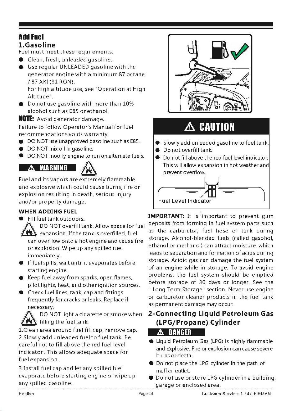
• Slowly add unleaded gasoline
to
fuel tank.
• Do
not
overfill
tank.
• Do
not
fill above
the
red fuel level indicator.
This will allow expansion in
hot
weather and
prevent overflow.
(------==1r~,
Fuel
Level
Indicator
I
IMPORTANT:
It
is·
important
to
prevent
gum
deposits
from
forming
in fuel system parts such
as
the
carburetor, fuel hose
or
tank
during
storage.
Alcohol-blended
fuels (called gasohol,
ethanol
or
methanol)
can
attract
moisture,
which
leads
to
separation and
formation
of
acids
during
storage.
Acidic
gas can
damage
the
fuel system
of
an
engine
while
in storage. To avoid
engine
problems,
the
fuel system should
be
emptied
before
storage
of
30
days
or
longer.
See
the
" Long Term Storage" section.
Never
use
engine
or
carburetor
cleaner
products
in
the
fuel
tank
as
permanent
damage
may
occur.
2-Connecting
Liquid
Petroleum
Gas
(LPG/Propane)
Cylinder
A
DANGER
• Liquid Petroleum
Gas
(LPG)
is
highly flammable
and explosive. Fire
or
explosion can cause severe
burns
or
death.
• Do
not
place
the
LPG
cylinder in the path
of
muffler outlet.
•
Do
not
use
or
store
LPG
cylinder
in
a
building,
garage
or
enclosed
area.
English
Page
13
Customer
Service
1 -844
-FIRMAN
1
•
Do
not
check
for
leaks
with
a
lighted
match
or
flame.
• The
LPG
cylinder
valve
should
be
fully
closed
when
the
generator
is
not
in use
or
is
running
with
gasoline.
•
If
you
smell gas: close
off
the
gas supply. Make
sure
there
is
no
leak
before
using
the
generator.
£
WARNING
• Device used
for
handling
LPG
must
be
installed
and
used
in
strict conformance with
NFPA
58
(Liquefied Petroleum
Gas
Code) and
NFPA
54
(National
Fuel
Gas)
and all other
codes,
regulations
and manufacturer recommendations.
•
Never
use a gas
container,
LPG
connector
hose,
LPG
cylinder
or
any
other
fuel
item
that
is
damaged
or
appears
damaged.
• The
LPG
cylinder
valve
shou
Id
be
fully
closed
when
the
generator
is
not
in
use
or
is
running
with
gasoline.
• The
regulator/hose
assembly
and
cylinder
valve
must
be
inspected
before
each use
for
leaks
or
sign
of
damages.
•
If
you
smell gas: close
off
the
gas supply. Spray
a soapy
water
solution
to
check all connections
for
leaks
before
attempting
to
use generator.
Contact
a
qualified
technician
to
inspect and
repair
the
LPG
system
if
a leak
found
before
using
the
generator.
■ Use
only
20
or
30
lb
capacity
cylinders
with
Type
1,
right
hand
Acme
threads
with
this
generator.
Verify
the
re-qualification
date
on
the
tank
has
not
expired.
Do
not
use rusted
or
damaged
cylinders.
■
All
new
cylinders
must
be
purged
of
air
and
moisture
prior
to
filling.
Used
cylinders
that
have
not
been
plugged
or
kept
closed
must
also
be
purged.
The
purging
process
should
be
done
by
your
propane
gas
supplier.
■
Do
not
connect
ordisconnectthe
LPG
cylinder
in enclosed area.
■
Do
not
install
or
replace
the
LPG
cylinder
near
open
flames,
pilot
lights,
or
sparking
electrical
equipment
such
as
power
tools,
welders
and
grinders.
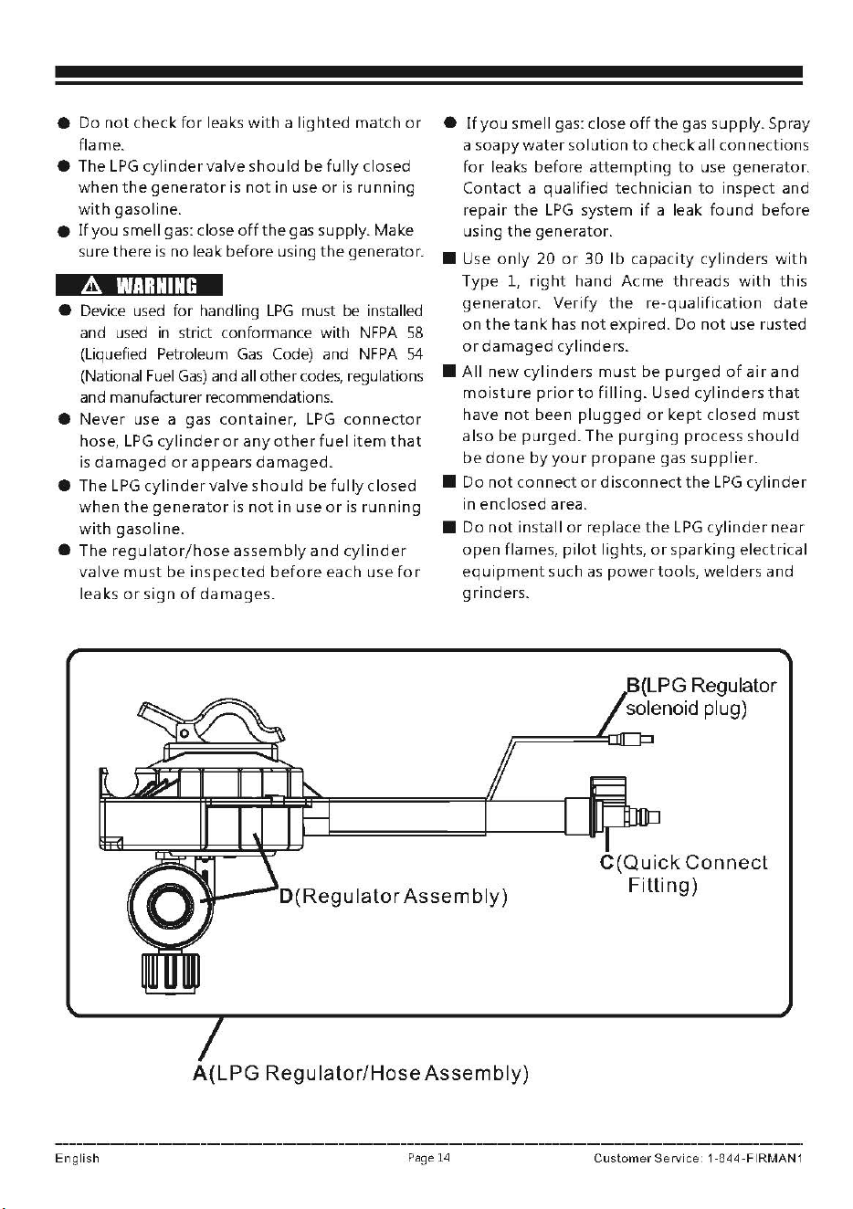
D(Regulator
Assembly)
C(Quick
Connect
Fitting)
A(LPG
Regulator/Hose
Assembly)
English
Page
14
Customer
Service
1-844-FIRMAN
1
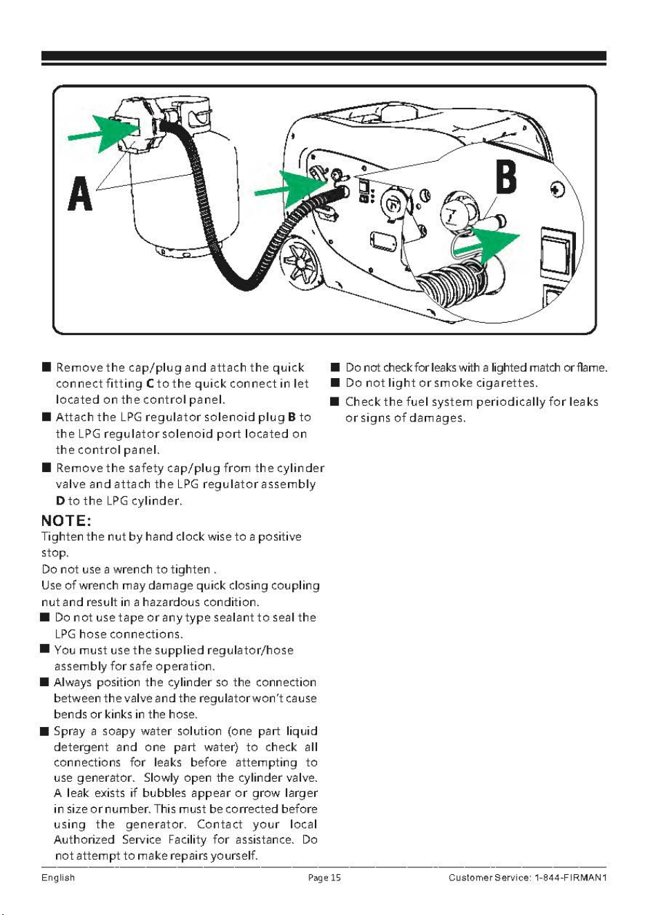
■ Remove
the
cap/plug
and
attach
the
quick
connect
fitting
C
to
the
quick
connect
in
let
located
on
the
control
panel.
■
Attach
the
LPG
regulator
solenoid
plug
B
to
the
LPG
regulator
solenoid
port
located
on
the
control
panel.
■ Remove
the
safety
cap/plug
from
the
cylinder
valve
and
attach
the
LPG
regulator
assembly
D
to
the
LPG
cylinder.
NOTE:
Tighten
the
nut
by
hand clock wise
to
a positive
stop.
Do
not
use a wrench
to
tighten.
Use
of
wrench may damage quick closing coupling
nut
and result in a hazardous condition.
■
Do
not
use tape
or
any
type
sealant
to
seal
the
LPG
hose connections.
■ You
must
use
the
supplied
regulator/hose
assembly
for
safe
operation.
■
Always position
the
cylinder
so
the connection
between
the
valve and the regulator
won't
cause
bends
or
kinks in the hose.
■
Spray a soapy water solution (one part
liquid
detergent and one part water)
to
check all
connections
for
leaks before
attempting
to
use generator. Slowly open the cylinder valve.
A leak exists
if
bubbles appear
or
grow
larger
in
size
or
number. This must be corrected before
using
the
generator.
Contact
your
local
Authorized Service Facility
for
assistance. Do
not
attempt
to
make repairs yourself.
■ Do not
check
for
leaks
with a lighted match orflame.
■
Do
not
light
or
smoke
cigarettes.
■ Check
the
fuel
system
periodically
for
leaks
or
signs
of
dam ages.
English
Page
15
Customer
Service:
1-844-F
IRMAN
1
&.
CAUTION
•
LPG
under
pressure
is
highly
flammable
and
can cause a
fire
or
explosion
if
ignited.
•
LPG
is
heavier
than air and
can
accumulate
in
confined
spaces
and
low
places
in
the event
of
a
leak.
•
LPG
has
ad
istinctive
odor
to
help
detect
potential
leaks.
•
Do
not
allow
children
to
tamper
or
play
with
the
LPG
cylinder.
• In
the
event
of
an
LPG
fire, flames
should
not
be
extinguished
unless
by
doing
so
the
fuel
supply
valve can
be
turned
off.
If
the
fire
is
extinguished
and
a
supply
of
fuel
is
not
turned
off,
an
explosion
hazard
greater
than
the
fire
hazard cou Id
be
created.
•
Keep
a
fire
extinguisher
near
the
generator
all
the
time.
•
Always
keep
the
LPG
cylinder
in an
upright
position.
• Do
not
subject
LPG
cylinder
to
excessive heat.
•
Contact
with
liquid
contents
of
the
cylinder
will
cause
freeze
burns
to
the
skin.
•
An
LPG
cylinder
not
connected
for
use
shall
not
be
stored
in
the
vicinity
of
the
generator.
•
When
transporting
and
storing,
turn
off
the
cylinder
valve
and
fuel
selector
switch,
and
disconnect
the
cylinder.
3-Permanent
Connection
to
a
large
Propane
supply
tank:
In the instance that you would need
to
connect
your
generator
to
a large propane Supply tank,
larger than 20
or
30
lb
DOT cylinder,
it
is
recommended
to
contact your
Gas
Equipment
Company. Various equipment
for
use with
LPG,
is
required
for
proper conformance
to
all
NFPA
regulations. Your
Gas
Equipment Company
can
help
you
select and install the proper regulator,
fittings and connections
to
meet all the Codes
and manufacturer regulations.
Each
installation
may be different and will required proper equipment.
Contact
your
Gas
Equipment Company
to
assure
that
you are meeting all
NFPA
58
(Liquefied
Petroleum
Gas
Code) and
NFPA
54
(National
Fuel
Gas)
Codes.
Operation
at
High
Altitude
At
altitudes
over
5,000
feet(l524
meters),
a
minimum
85
octane/
85 AKI (89 RON)
gasoline
is
acceptable.
The
density
of
air at high
altitude
is
lower
than
at
sea
level. Engine
power
is
reduced
as
the
air
mass and
air-fuel
ratio decrease.
Engine
power
and
generator
output
will
be
reduced
approximately
3.5%
for
every 1000
feet
of
elevation
above
sea level. This
is
a
natural
trend
and
cannot
be
changed
by
adjusting
the
engine.
At
high
altitudes
increased exhaust emissions can also result
due
to
the
increased
enrichment
of
the
air
fuel ratio.
Other
high
altitude
issues
can
include
hard
starting,
increased
fuel
consumption
and
spark
plug
fouling.
To
alleviate
high
altitude
issues
other
than
the
natural
power
loss,
FIRMAN
can
provide
a
high
a
It
it
u
de
ca
rb
u
reto
r
main
jet.
The
a I
tern
at
ive
main
jet
and installation instructions can be
obtained
by
contacting
Customer
Support.
Installation instructions are also available in
the
Technical Bulletin area
of
the
FIRMAN internet site.
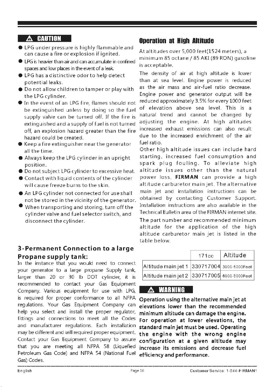
The
part
number
and
recommended
minimum
altitude
for
the
application
of
the
high
altitude
carburetor
main
jet
is
listed
in
the
table
below.
171cc
Altitude
Altitude
main
jet
1
330717004
300
0
-6000Feet
Altitude
mainjet2
330717005
6000-8000Feet
&.
WARNING
Operation using the alternative main
jet
at
elevations lower than the recommended
minimum altitude
can
damage the engine.
For operation at lower elevations,
the
standard main
jet
must be used. Operating
the
engine
with
the
wrong
engine
configuration
at
a given
altitude
may
increase its emissions and decrease fuel
efficiency and performance.
English
Page
16
Customer
Service
1
-844-FIRMAN
1
Grounding
The National Electric Code requires
your
generator
must
be
properly
connected
to
an
appropriate
ground
to
help prevent electric shock.
.&.
WARNING
Failure
to
properly
ground
the
generator
can
result
in
electric
shock.
A
ground
terminal
connected
to
the
frame
of
the
generator
has
been
provided
on
the
control
panel.
For
remote
grounding,
connect
of
a
length
of
heavy
gauge
(12
AWG
minimum)
copper
wire
between
the
generator
ground
terminal
and
a
copper
rod
driven
into
the
ground.
We
strongly
recommend
that
you
consult
with
a
qualified
electrician
to
ensure
compliance
with
local
electrical
codes.
THERE
IS
A PERMANENT CONDUCTOR
BETWEEN
THE
GEN
ERA
TOR (STATOR
WINDING)
AND
THE
FRAME.
connecting
to
a
Building's
Electrical
svstem
Connections
for
standby
power
to
a
building's
electrical
system
must
be
made
by
a
qualified
electrician.
The
connection
must
isolate
the
generator
power
from
utility
power
or
other
alternative
power
sources
and
must
comply
with
all
applicable
laws
and
electrical
codes.
&
WARNING
&
Generator
voltage
could
cause
electrical
shock
or
burn
resulting
In
death
or
serious
InJury.
• Use
approved
transfer
equipment
to
prevent
backfeed
by
isolating
generator
from
electric
utility
workers.
•
When
using
generator
for
backup
power,
notify
utility
company.
• Use a
ground
fault
circuit
interrupter
(GFCI) in
any
damp
or
highly
conductive
area, such
as
metal
decking
or
steel
work.
• DO NOT
touch
bare wires
or
receptacles.
• DO NOT use
generator
with
electrical cords
which
are
worn,frayed,
bare
or
otherwise
damaged.
• DO NOT
operate
generator
in
the
rain
or
wet
weather.
• DO NOT
handle
generator
or
electrical
cords
while
standing
in water,
while
barefoot
,
or
while
hands
or
feet
are
wet.
• DO NOT
allow
unqualified
persons
or
children
to
operate
or
service
generator.
English
Page
17
Customer
Service
1
-844-FIRMAN
1
OPERATION
Generator
location
&
WARNING
Make sure
you
review each warning in
order
to
prevent fire hazard.
■
Keep
area clear
of
inflammables
or
other
hazardous materials.
■
Select a site
that
is
dry, well ventilated and
protected from
the
weather.
■
Keep
exhaust pipe clear
of
foreign objects.
■
Keep
generator away
from
open flame.
■
Keep
generator on a stable and level surface.
A
CAUTION
Tilting
can cause
fuel
spillage.
■
Do
not
block generator air vents
with
paper
or
other
material.
A
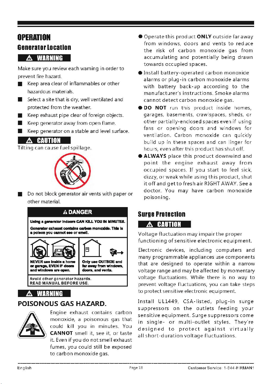
DANGER
U.lng •
a-ralor
Ind-,,
CAN
KILL
YOU
IN
MINUTES.
GenerwlDr
ahauat
contain•
carbon
monmd•.
Thll
11
•
pol1on
you
cu,r,ot
- or 1mell.
©~
0
"'➔
NEVER,_
lnllde •
homa
Only
UN
OUTSIDE
and
or
gar
■
ge,
EVEN
IF
doon
flr-fnlm
win-.
andwln_.,._n,
doan,
and wnta.
Avoid
other
generator
hazards.
READ
MANUAL
BEFORE USE.
&
WARNING
POISONOUS GAS HAZARD.
Engine exhaust
contains
carbon
monoxide,
a
poisonous
gas
that
could
kill
you
in
minutes.
You
CANNOT
smell it, see it,
or
taste
it. Even
if
you
do
not
smell exhaust
fumes,
you
could
still
be
exposed
to
carbon
monoxide
gas.
•
Operate
this
product
ONLY
outside
far
away
from
windows,
doors
and
vents
to
reduce
the
risk
of
carbon
monoxide
gas
from
accumulating
and
potentially
being
drawn
towards
occupied
spaces.
•
Install
battery-operated
carbon
monoxide
alarms
or
plug-in
carbon
monoxide
alarms
with
battery
back-up
according
to
the
manufacturer's
instructions.
Smoke
alarms
cannot
detect
carbon
monoxide
gas.
•
DO
NOT
run
th
is
product
inside homes,
garages, basements, crawlspaces, sheds,
or
other
pa
rt i
ally-enclosed
spaces even
if
using
fans
or
opening
doors
and
windows
for
ventilation.
Carbon
monoxide
can
quickly
build
up
in these spaces
and
can
linger
for
hou
rs,
even
afte
r
this
product
has
sh
ut
off.
eALWAYS
place
this
product
downwind
and
point
the
engine
exhaust
away
from
occupied
spaces.
If
you
start
to
feel sick,
dizzy,
or
weak
while
using
this
product,
shut
it
off
and
get
to
fresh
air
RIGHT AWAY. See a
doctor.
You
may
have
carbon
monoxide
poisoning.
surge
Protection
A
CAUTION
Voltage
fluctuation
may
impairthe
proper
functioning
of
sensitive
electronic
equipment.
Electronic devices,
including
computers
and
many
programmable
appliances use
components
that
are designed
to
operate
within
a
narrow
voltage
range
and
may
be
affected
by
momentary
voltage
fluctuations.
While
there
is
no
way
to
prevent
voltage
fluctuations,
you
can
take
steps
to
protect
sensitive electronic
equipment.
Install
UL1449,
CSA-listed,
plug-in
surge
suppressors
on
the
outlets
feeding
your
sensitive
eq u
ipment.
Surge
suppressors
come
in
single-
or
multi-outlet
styles.
They're
designed
to
protect
against
virtually
all
short-duration
voltage
flu
c
tuations.
English
Pa
ge 18
Customer
Service
1-844-FIRMAN
1
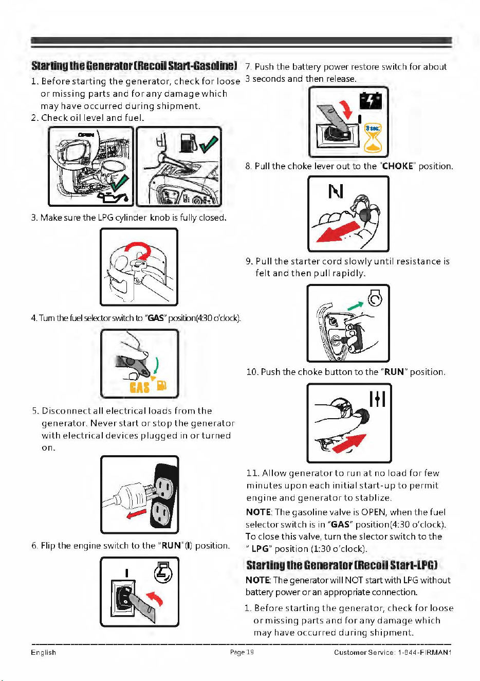
Starting
the
GenBl'atorlRecoU
Stan-GasOline)
7.
Push
the
battery power restore switch
for
about
1.
Before
starting
the
generator,
check
for
loose
3 seconds and then release.
or
missing
parts
and
for
any
damage
which
may
have
occurred
during
shipment.
2.
Check
oil
level
and
fuel.
3.
Make sure
the
LPG
cylinder knob
is
fully closed.
4.
Tum
the
fuel
selector
switch
to
"GAS"
positi:m(4:30
o'clock).
5.
Disconnect
all
electrical
loads
from
the
generator.
Never
start
or
stop
the
generator
with
electrical
devices
plugged
in
or
turned
on.
6.
Flip
the
engine switch
to
the
"RUN"(I) position.
8.
Pull
the
choke lever
out
to
the
"CHOKE"
position.
9. Pull
the
starter
cord
slowly
until
resistance
is
felt
and
then
pull
rapidly.
10. Push
the
choke
button
to
the
"RUN" position.
11.
Allow
generator
to
run
at
no
load
for
few
minutes
upon
each
initial
start-up
to
permit
engine
and
generator
to
stablize.
NOTE: The
gasoline
valve
is
OPEN,
when
the
fuel
selector
switch
is
in
"GAS"
position(4:30 o'clock).
To close
this
valve,
turn
the
slector
switch
to
the
"LPG"
position
(1:30 o'clock).
Starling
the
Generator
IRecoil
Start-lPGJ
NOTE: The generator
will
NOT start with
LPG
without
battery power
or
an appropriate connection.
L
Before
starting
the
generator,
check
for
loose
or
missing
parts
and
for
any
damage
which
may
have
occurred
during
shipment.
English
Page
19 Cus
tomer
Service
1 -844
-FIRMAN
1
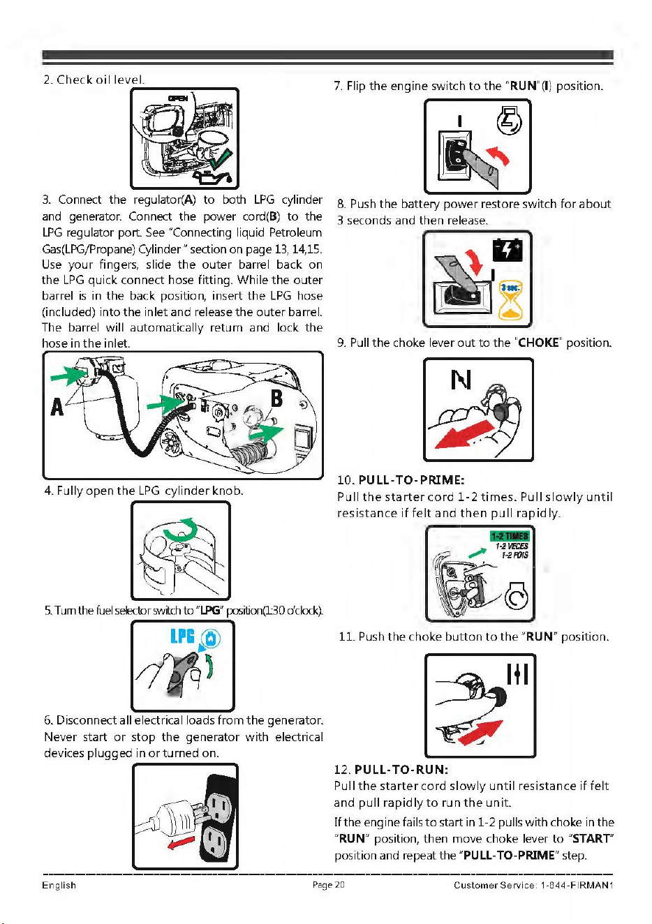
3.
Connect the regulator(A)
to
both
LPG
cylinder
and generator. Connect the power
cord(B)
to
the
LPG
regulator port.
See
"Connecting liquid Petroleum
Gas(LPG/Propane)
Cylinder" section on page
13,
14,15.
Use
your fingers, slide
the
outer
barrel back on
the
LPG
quick connect hose fitting. While
the
outer
barrel
is
in
the
back position, insert
the
LPG
hose
(included) into
the
inlet and release
the
outer
barrel.
The barrel will automatically return and lock
the
hose
in
the
inlet.
4. Fully
open
the
LPG
cylinder knob.
5.
Turn
the
fuel
selector
swtch
to
"LPG"
position(l30
o'clock).
6.
Disconnect all electrical loads
from
the
generator.
Never start
or
stop
the
generator
with
electrical
devices plugged in
or
turned on.
7.
Flip
the
engine switch
to
the
"RUN"(I) position.
8.
Push
the
battery power restore switch
for
about
3 seconds and then release.
9.
Pull
the
choke lever
out
to
the
"CHOKE"
position.
10.
PULL-TO-PRIME:
Pull
the
starter
cord
1-2
times.
Pull
slowly
until
resistance
if
felt
and
then
pull
rapidly.
-
1·2VB:ES
.,,,,,,
1-21'1}/S
11.
Push
the
choke
button
to
the
"RUN" position.
12.
PULL-TO-RUN:
Pull
the
starter
cord
slowly
until
resistance
if
felt
and
pull
rapidly
to
run
the
unit.
If
the engine fails
to
start in 1-2 pu
lls
with choke in the
"RUN" position, then move choke lever
to
"START"
position and repeat the "PULL-TO-PRIME" step.
English
Page
20
Cus
tomer
Service
1-
8
44-FIRMAN
1
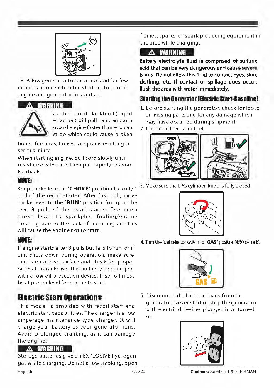
13.
Allow
generator
to
run
at
no
load
for
few
minutes
upon
each
initial
start-up
to
permit
engine
and
generator
to
stablize.
A
WARNING
~
Starter
cord
kickback(rapid
d '
~
retraction)
will
pull
hand
and
arm
A
~
toward
engine
faster
than
you
can
(~
'"'---
~'
let
go
which
could
cause
broken
bones, fractures, bruises,
or
sprains
resulting
in
serious injury.
When
starting
engine,
pull
cord
slowly
until
resistance
is
felt
and
then
pull
rapidly
to
avoid
kickback.
Keep
choke
lever
in
"CHOKE"
position
for
only
1
pull
of
the
recoil
starter.
After
first
pull
,
move
choke
lever
to
the
"RUN"
position
for
up
to
the
next
3
pulls
of
the
recoil
starter.
Too
much
choke
leads
to
sparkplug
fouling/engine
flooding
due
to
the
lack
of
incoming
air.
This
will
cause
the
engine
not
to
start.
NIITE;
If
engine
starts
after
3
pulls
but
fails
to
run,
or
if
unit
shuts
down
during
operation,
make
sure
unit
is
on
a
level
surface
and
check
for
proper
oil
level
in
crankcase. This
unit
may
be
equipped
with
a
low
oil
protection
device.
If
so,
oil
mu
st
be
at
proper
level
for
engine
to
start.
Electric
Start
Operations
This
model
is
provided
with
recoil
start
and
electric
start
capabilities.
The
charger
is a
low
amperage
maintenance
type
charger.
It
will
charge
your
battery
as
your
generator
runs.
Avoid
prolonged
cranking,
as
it
can
damage
the
engine
,
A
WARNING
Storage
batteries
give
off
EXPLOSIVE
hydrogen
gas
while
charging.
Do
not
allow
smoking,
open
flames,
sparks,
or
spark
producing
equipment
in
the
area
while
charging.
A
WARNING
Battery
electrolyte
fluid
is
comprised
of
sulfuric
acid
that
can
be
very
dangerous
and
caus
e
severe
burns.
Do
not allow
this
fluid
to contact
eyes,
skin,
clothing,
etc.
If
contact or spillage
does
occur,
flush
the
area
with
water immediately.
s1arling
lhe
Genennor
meclric
s1an~Gasoln11J
L
Before
starting
the
generator,
check
for
loose
or
missing
parts
and
for
any
damage
which
may
have
occurred
during
shipment.
2.
Check
oi
I
level
and
fuel.
3. Make sure the
LPG
cylinder knob
is
fully
closed.
4.
Tum
the
fuel
selectorsw~ch
to
"GAS"
positbn(4:30 dcbck).
~
IAI
i1
S.
Disconnect
all
electrical
loads
from
the
generator.
Never
start
or
stop
the
generator
with
electrical
devices
pl
u
gged
in
or
turned
on.
English
Pag
e
21
Cus
tomer
Service
1 -8
44-FIRMAN
1
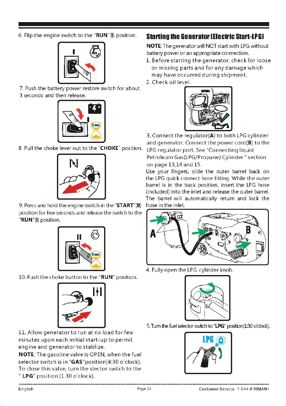
6.
Flip
the
engine switch
to
the
"RUN"(I) position.
•©
~
7.
Push
the battery power restore switch
for
about
3 seconds and then release.
8.
Pull
the
choke lever
out
to
the
"CHOKE"
position.
~
~
-<J
9.
Press
and hold
the
engine switch in
the
"START'
(II)
position
for
few seconds and release the switch
to
the
"RUN"(I) position.
II
CC)
~
10. Push
the
choke
button
to
the
"RUN" position.
11.
Allow
generator
to
run
at
no
load
for
few
minutes
upon
each
initial
start-up
to
permit
engine
and
generator
to
stablize.
NOTE: The
gasoline
valve is OPEN,
when
the
fuel
selector
switch
is
in
"GAS"position(4:30
o'clock).
To
close
this
valve,
turn
the
slector
switch
to
the
"LPG"
position
(1.30
o'clock).
Staning
the
Generator
(Electric
Start-LPGJ
NOTE:
The generator will NOT start with
LPG
without
battery power
or
an
appropriate connection.
L
Before
starting
the
generator,
check
for
loose
or
missing
parts
and
for
any
damage
which
may
have
occurred
during
shipment.
2.
Check
oil
level.
3.
Connect
the
regulator(A)
to
both
LPG
cylinder
and
generator.
Connect
the
power
cord(B)
to
the
LPG
regulator
port.
See
"Connecting
liquid
Petroleum
Gas(LPG/Propane)
Cylinder"
section
on
page
13,14
and
15.
Use
your
fingers, slide
the
outer
barrel back on
the
LPG
quick
connect hose fitting.
While
the
outer
barrel
is
in
the
back position, insert
the
LPG
hose
(included)
into
the
inlet and release
the
outer
barrel.
The barrel will automatically return and lock
the
hose in
the
inlet.
4. Fully
open
the
LPG
cylinder
knob.
S.
Tum
the
fuel
selector
sv.ntr:h
to
"LPG"
positbn(l30
o'clock).
English
Page
22
Customer
Service
1 -844
-FIRMAN
1
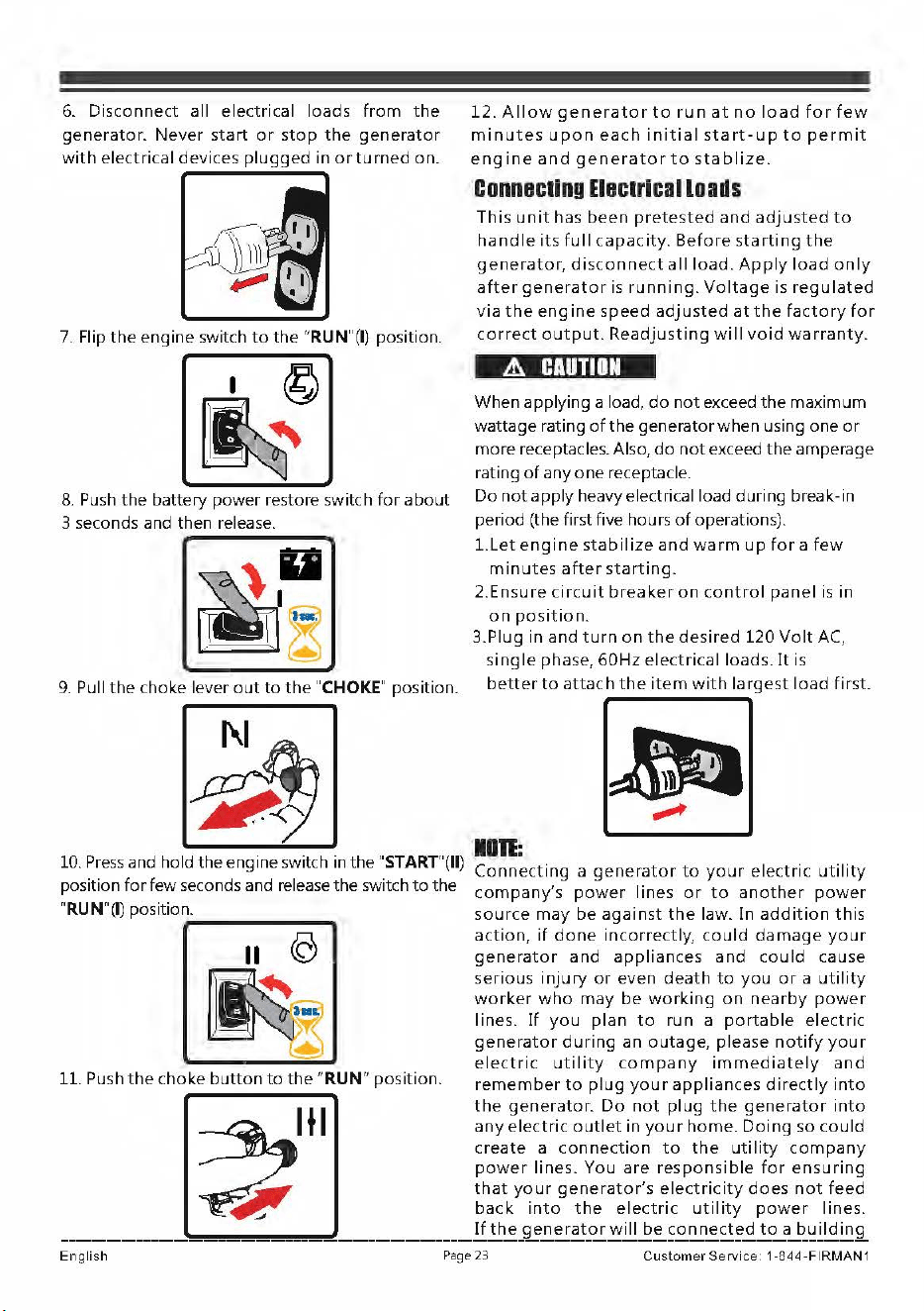
6.
Disconnect
all
electrical
loads
from
the
generator.
Never
start
or
stop
the
generator
with
electrical
devices
plugged
in
or
turned
on.
7.
Flip
the
engine
switch
to
the
"RUN"(I) position.
8.
Push
the
battery
power
restore switch
for
about
3 seconds and then release.
9.
Pull
the
choke lever
out
to
the
"CHOKE" position.
10.
Press
and hold
the
engine switch in the "START"(II)
position
for
few
seconds and release
the
switch
to
the
"RUN"(I) position.
-------
11
e
~
11. Push
the
choke
button
to
the
"RUN"
position.
12.
Allow
generator
to
r u n
at
no
load
for
few
minutes
upon
each
initial
start-up
to
permit
engine
and
generator
to
stablize
.
ConnBCling
EIBClrical
loads
This
unit
has
been
pretested
and
adjusted
to
handle
its
full
capacity.
Before
starting
the
generator,
disconnect
all
load.
Apply
load
only
after
generator
is
running.
Voltage
is
regulated
via
the
engine
speed
adjusted
at
the
factory
for
correct
output.
Readjusting
will
void
warranty.
A
CAUTION
When
applying a load,
do
not
exceed
the
ma
x
imum
wattage
rating
of
the
generator
when
using
one
or
more
receptacles. Also,
do
not
exceed
the
amperage
rating
of
anyone
receptacle.
Do
not
apply
heavy electrical load
during
break-in
period (the first five hours
of
operations).
Llet
engine
stabilize
and
warm
up
for
a
few
minutes
after
starting.
2.Ensure
circuit
breaker
on
control
panel
is in
on
position.
3.Plug
in
and
turn
on
the
desired
120
Volt
AC,
single
phase,
60Hz
electrical
loads.
It
is
better
to
attach
the
item
with
largest
load
first.
~
.,,,,,,,,,
1111:
Connecting
a
generator
to
your
electric
utility
company's
power
lines
or
to
another
power
source
may
be
against
the
law.
In
addition
this
action,
if
done
incorrectly,
could
damage
your
generator
and
appliances
and
could
cause
serious
injury
or
even
death
to
you
or
a
utility
worker
who
may
be
working
on
nearby
power
lines.
If
you
plan
to
run
a
portable
electric
generator
during
an
outage,
please
notify
your
electric
utility
company
immediately
and
remember
to
plug
your
appliances
directly
into
the
generator
.
Do
not
plug
the
generator
into
any
electric
outlet
in
your
home.
Doing
so
could
create
a
connection
to
the
utility
company
power
lines.
You
are
responsible
for
ensuring
that
your
generator's
electricity
does
not
feed
back
into
the
electri
c
utility
power
lines
.
If
the
generator
will
be
connected
to
a
building
English
Pag
e
23
Cu
s
tomer
Servic
e 1 ·844
·FIRMAN
1
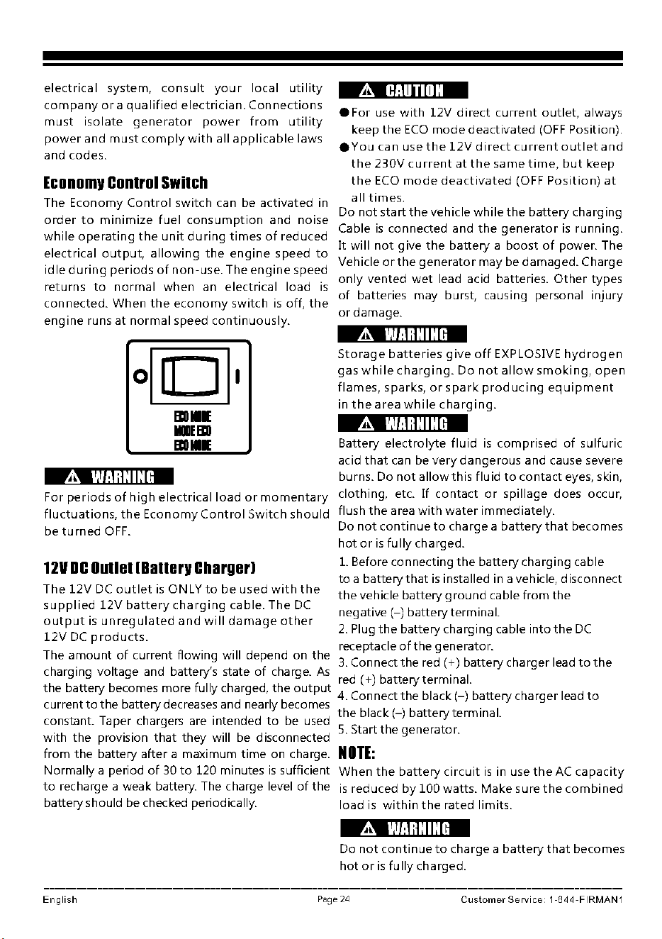
electrical
system,
consult
your
local
utility
company
or
a
qualified
electrician.
Connections
must
isolate
generator
power
from
utility
power
and
must
comply
with
all
applicable
laws
and
codes.
Economv
Control
Switch
.it.
CAUTION
eFor
use
with
12V
direct
current
outlet,
always
keep
the
ECO
mode
deactivated
(OFF
Position).
•
You
can use
the
12V
direct
current
outlet
and
the
230V
current
at
the
same
time,
but
keep
the
ECO
mode
deactivated
(OFF
Position)
at
The
Economy
Control
switch
can be
activated
in
all
times.
Do
not
start
the
vehicle
while
the
battery
charging
order
to
minimize
fuel
consumption
and
noise
while
operating
the
unit
during
times
of
reduced
Cable
is
connected
and
the
generator
is
running.
It
will
not
give
the
battery
a
boost
of
power. The
electrical
output,
allowing
the
engine
speed
to
Vehicle
or
the
generator
may
be
damaged.
Charge
idle
during
periods
of
non-use.
The
engine
speed
returns
to
normal
when
an
electrical
load
is
only
vented
wet
lead acid batteries.
Other
types
of
batteries
may
burst, causing personal
injury
connected.
When
the
economy
switch
is
off,
the
or
damage.
engine
runs
at
normal
speed
continuously.
.it.
WARNING
Bll
■
IE
IIIIIBII
Bll
■
IE
For
periods
of
high
electrical
load
or
momentary
fluctuations,
the
Economy
Control
Switch
should
be
turned
OFF.
12VDC
Outlet
IBatterv
Charger!
The
12V
DC
outlet
is
ONLY
to
be
used
with
the
supplied
12V
battery
charging
cable.
The
DC
output
is
unregulated
and
will
damage
other
12V
DC
products.
The
amount
of
current
flowing will depend on
the
A
WARNING
Storage
batteries
give
off
EXPLOSIVE
hydrogen
gas
while
charging.
Do
not
allow
smoking,
open
flames,
sparks,
or
spark
producing
equipment
in
the
area
while
charging.
A
WARNING
Battery
electrolyte
fluid
is
comprised
of
sulfuric
acid
that
can be
very
dangerous
and cause severe
burns. Do
not
allow
this
fluid
to
contact
eyes, skin,
clothing,
etc.
If
contact
or
spillage
does occur,
flush
the
area
with
water
immediately.
Do
not
continue
to
charge
a
battery
that
becomes
hot
or
is
fully
charged.
1.
Before
connecting
the
battery
charging
cable
to
a
battery
that
is
installed in a vehicle,
disconnect
the
vehicle
battery
ground
cable
from
the
negative(-)
battery
terminal.
2.
Plug
the
battery
charging
cable
into
the
DC
receptacle
of
the
generator.
3.
Connect
the
red
(+)battery
charger
lead
to
the
charging
voltage
and battery's state
of
charge.
As
d I ) b .
1
re
+
atteryterm1na.
the
battery
becomes
more
fully charged,
the
output
4
. Connect
the
black(-)
battery
charger
lead
to
currentto
the
battery
decreases and nearly becomes
the
black(-)
battery
terminal.
constant. Taper chargers are intended
to
be used
5.
Start
the
generator.
with
the
provision
that
they
will be disconnected
from
the
battery
after
a
maximum
time
on charge.
NOTE:
Normally
a period
of
30
to
120 minutes
is
sufficient
When
the
battery
circuit
is
in use
the
AC
capacity
to
recharge a weak battery. The charge level
of
the
is
reduced
bylO0watts.
Make
sure
the
combined
battery
should be checked periodically.
load
is
within
the
rated
limits
.
English
.it.
WARNING
Do
not
continue
to
charge
a
battery
that
becomes
hot
or
is
fully
charged.
Page
2'1
CustomerService
1-844-FIRMAN1
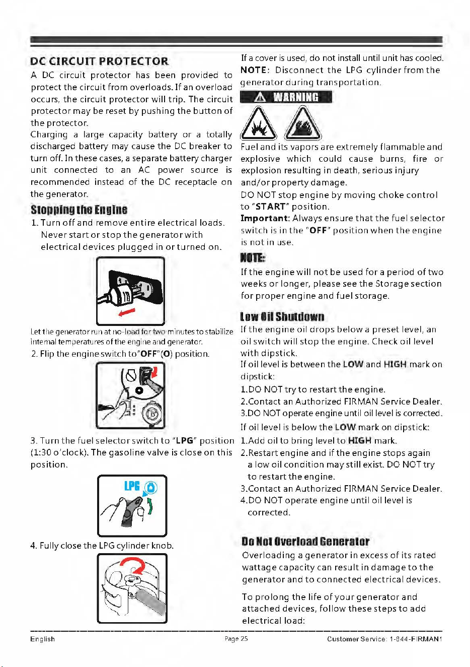
DC
CIRCUIT
PROTECTOR
If
a cover
is
used,
do
not
install until
unit
has
cooled.
A DC
circuit
protector
has
been
provided
to
NOTE:
Disconnect
the
LPG
cylinder
from
the
generator
during
transportation.
protect
the
circuit
from
overloads.
If
an
overload
occurs,
the
circuit
protector
will
trip.
The
circuit
protector
may
be
reset
by
pushing
the
button
of
the
protector.
Charging
a
large
capacity
battery
or
a
totally
discharged
battery
may
cause
the
DC
breaker
to
turn
off.
In
these
cases, a separate
battery
charger
unit
connected
to
an
AC
power
source
is
recommended
instead
of
the
DC
receptacle
on
the
generator.
Stopping
the
Engine
1.
Turn
off
and
remove
entire
electrical
loads.
Never
start
or
stop
the
generator
with
electrical
devices
plugged
in
or
turned
on.
Let
the
generator run
at
no-load
for
tw
o minutes
to
stabilize
internal temperatures
of
the engine and generator.
2.
Flip
the
engine
switch to"OFF"(O) position.
~
3.
Turn
the
fuel
selector
switch
to
"LPG"
position
(1:30
o'clock).
The
gasoline
valve
is
close
on
this
position.
4. Fully close
the
LPG
cylinder
knob.
A
WARNING
Fuel
and
its
vapors
are
extremely
flammable
and
explosive
which
could
cause
burns
,
fire
or
explosion
resulting
in
death,
serious
injury
and/or
property
damage.
DO
NOT
stop
engine
by
moving
choke
control
to
"START"
position.
Important:
Always
ensure
that
the
fuel
selector
switch
is
in
the
"OFF"
position
when
the
engine
is
not
in
use.
HIE:
If
the
engine
will
not
be
used
for
a
period
of
two
weeks
or
longer,
please
see
the
Storage
section
for
proper
engine
and
fuel
storage.
low
Iii
Shutdown
If
the
engine
oil
drops
below
a
preset
level,
an
oil
switch
will
stop
the
engine.
Check
oil
level
with
dipstick.
If
oil
level
is
between
the
LOW and
HIGH
mark
on
dipstick:
1.DO
NOT
try
to
restart
the
engine.
2.Contact
an
Authorized
FIRMAN Service Dealer.
3.DO NOT operate engine until oil level
is
corrected.
If
oil
level
is
below
the
LOW
mark
on
dipstick:
1.Add
oil
to
bring
level
to
HIGH
mark.
2.Restart
engine
and
if
the
engine
stops
again
a
low
oil
condition
may
still
exist. DO NOT
try
to
restart
the
engine.
3.Contact
an
Authorized
FIRMAN Service Dealer.
4.DO
NOT
operate
engine
until
oil
level
is
corrected.
Do
Nol
overload
Generator
Overloading
a
generator
in
excess
of
its
rated
wattage
capacity
can
result
in
damage
to
the
generator
and
to
connected
electrical
devices.
To
prolong
the
life
of
your
generator
and
attached
devices,
follow
these
steps
to
add
electrical
load:
English
P
ag
e
25
Customer
Service
1
-844-FIRMAN
1
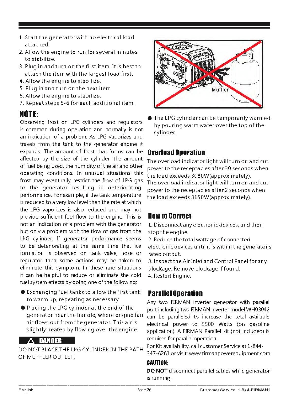
1.
Start
the
generator
with
no
electrical
load
attached.
2.
Allow
the
engine
to
run
for
several
minutes
to
stabilize.
3.
Plug
in
and
turn
on
the
first
item.
It
is
best
to
attach
the
item
with
the
largest
load
first.
4.
Allow
the
engine
to
stabilize.
5.
Plug
in
and
turn
on
the
next
item.
6.
Allow
the
engine
to
stabilize.
7.
Repeat
steps
5-6
for
each
additional
item.
NOTE:
Observing frost
on
LPG
cylinders and regulators
is
common
during
operation
and normally
is
not
an indication
of
a problem. As
LPG
vaporizes and
travels
from
the
tank
to
the
generator
engine
it
expands. The
amount
of
frost
that
forms can
be
affected
by
the
size
of
the
cylinder,
the
amount
of
fuel being used,
the
humidity
of
the
air
and
other
operating conditions. In unusual situations
this
frost may eventually restrict
the
flow
of
LPG
gas
to
the
generator
resulting
in
deteriorating
performance. For example,
if
the
tank
temperature
is
reduced
to
a
very
low
level
then
the
rate
at
which
the
LPG
vaporizes
is
also reduced and may
not
provide
sufficient fuel
flow
to
the
engine. This
is
not
an indication
of
a
problem
with
the
generator
but
only
a
problem
with
the
flow
of
gas
from
the
LPG
cylinder.
If
generator
performance seems
to
be deteriorating
at
the
same
time
that
ice
formation is observed
on
tank
valve, hose
or
regulator
then
some actions may
be
taken
to
eliminate this
symptom.
In
these rare situations
it
can be
helpful
to
reduce
or
eliminate
the
cold
fuel system effects
by
doing
one
of
the
following:
•
Exchanging
fuel
tanks
to
allow
the
first
tank
to
warm
up,
repeating
as
necessary
•
Placing
the
LPG
cylinder
at
the
end
of
the
generator
near
the
handle,
where
engine
fan
air
flows
out
from
the
generator.
This
air
is
slightly
heated
by
flowing
over
the
engine.
A
DANGER
DO
NOT
PLACE THE
LPG
CYLINDER
IN
THE PATH
OF
MUFFLER OUTLET.
•
The
LPG
cylinder
can
be
temporarily
warmed
by
pouring
warm
water
over
the
top
of
the
cylinder.
Overload
Operalion
The
overload
indicator
light
will
turn
on
and
cut
power
to
the
receptacles
after
30
seconds
when
the
load
exceeds
3080W(approximately).
The
overload
indicator
light
will
turn
on
and
cut
power
to
the
receptacles
after
2
seconds
when
the
load
exceeds
3150W(approximately).
How
to
Correct
1.
Disconnect
any
electronic
devices,
and
then
stop
the
engine.
2. Reduce
the
total
wattage
of
connected
electronic
devices
until
it
is
within
the
generator's
rated
output.
3.
Inspect
the
Air
Inlet
and
Control
Panel
for
any
blockage.
Remove
blockage
if
found.
4.
Restart Engine.
Parallel
Operalion
Any
two
FIRMAN inverter generator
with
parallel
port
including
two
FIRMAN inverter model WH03042
can be paralleled
to
increase
the
total
available
electrical
power
to
5500 Watts (on gasoline
application). A FIRMAN Parallel kit
(not
included)
is
required
for
parallel operation.
For Kit availability, call
customer
Service
at
1-844-
347-6261
or
visit: www.firmanpowerequipment.com.
CAUTION:
DO
NOT
disconnect
parallel cables
while
generator
is
running.
English
Page
26
Customer
Service
1 -844
-FIRMAN
1
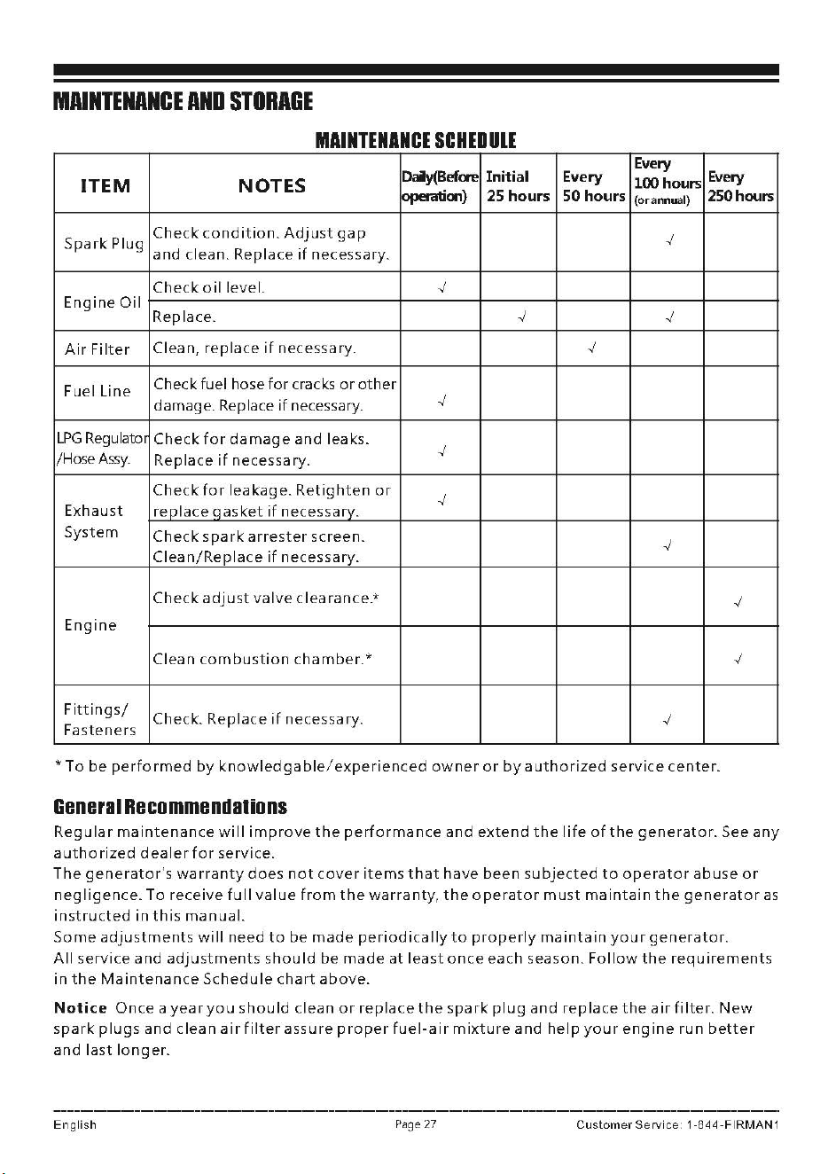
MAINTENANCE
AND
STORAGE
MAINTENANCE
SCHEDllE
Daiy(Befa-e
Initial Every
Every
Every
ITEM
NOTES
lOOhours
operatia,)
25 hours
50
hours
(or
annual)
250hours
Spark
Plug
Check
condition.
Adjust
gap
-./
and
clean.
Replace
if
necessary.
Check
oil
level.
-./
Engine
Oil
Replace.
-./
-./
Air
Filter
Clean,
replace
if
necessary.
-./
Fuel
Line
Check fuel hose
for
cracks
or
other
damage.
Replace
if
necessary.
-./
LPG
Regulato,
Check
for
damage
and
leaks.
-./
/HoseAssy.
Replace
if
necessary.
Check
for
leakage.
Retighten
or
-./
Exhaust
replace
qasket
if
necessary.
System
Check
spark
arrester
screen.
-./
Clean/Repla
ce
if
necessary.
Check
adjust
valve
clearance.*
-./
Engine
Clean
combustion
chamber.*
-./
Fittings/
Check.
Replace
if
necessary.
-./
Fasteners
*Tobe
performed
by
knowledgable
/
experienced
owner
or
by
authorized
service
c
ente
r.
Ganaral
Racommandalions
Regular
maintenance
will
improve
the
performance
and
extend
the
life
of
the
generator.
See
any
authorized
dealer
for
service.
The
generator
's
warranty
does
not
cover
items
that
have
been
subjected
to
operator
ab
use
or
negligence.
To
receive
full
value
from
the
warranty,
the
operator
m u
st
maintain
the
generator
as
instructed
in
this
manual.
Some
adjustments
will
need
to
be
made
periodically
to
properly
maintain
your
generator.
All
service
and
adjustments
should
be
made
at
least
once
each
season.
Follow
the
requirements
in
the
Maintenance
Schedule
chart
above.
Notice
Once
a
year
you
should
clean
or
replace
the
spark
plug
and
replace
the
air
filter.
New
spark
plugs
and
clean
air
filter
assure
proper
fuel-air
mixture
and
help
your
engine
run
better
and
last
longer.
English
P
age
27
Custom
er Se
rvic
e 1 -844
-FIRMAN
1
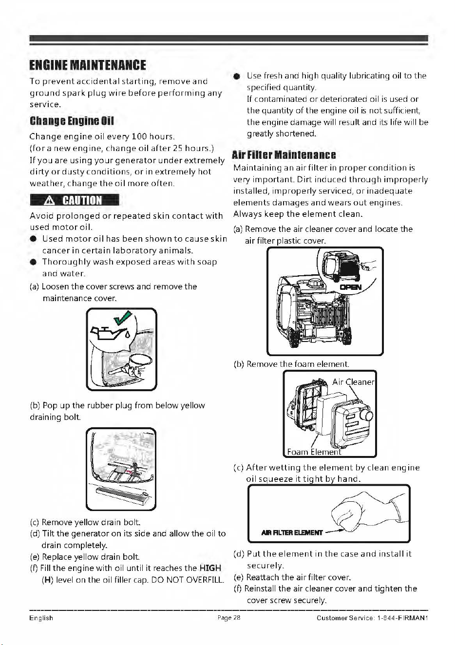
ENGINE
MAINTENANCE
To
prevent
accidental
starting,
remove
and
ground
spark
plug
wire
before
performing
any
service.
Change
Engine
Oil
Change
engine
oil
every
100
hours.
(for
a
new
engine,
change
oil
after
25
hours.)
If
you
are
using
your
generator
under
extremely
dirty
or
dusty
conditions
,
or
in
extremely
hot
weather,
change
the
oil
more
often.
&
CAUTION
Avoid
prolonged
or
repeated
skin
contact
with
used
motor
oil.
• Used
motor
oil
has
been
shown
to
cause
skin
cancer
in
certain
laboratory
animals.
•
Thoroughly
wash
exposed
areas
with
soap
and
water.
(a)
Loosen
the
cover screws and remove
the
maintenance cover.
(b) Pop
up
the
rubber
plug
from
below
yellow
draining
bolt.
(c) Remove yellow drain bolt.
(d)
Tilt
the
generator
on
its side and
allow
the
oil
to
drai
n completely.
(e)
Replace
yellow
drain bolt.
(f) Fill
the
engine
with
oil
until
it
reaches
the
HIGH
(H) level
on
the
oil
filler
cap. DO NOT
OVERFILL.
• Use fresh and
high
quality
lubricating oil
to
the
specified quantity.
If
contaminated
or
deteriorated
oil
is
used
or
the
quantity
of
the
engine
oil
is
not
sufficient,
the
engine
damage
will
result and its life
will
be
greatly
shortened.
Air
Filler
Maintenance
Maintaining
an
air
filter
in
proper
condition
is
very
important.
Dirt
induced
through
improperly
installed,
improperly
serviced,
or
inadequate
elements
d
amages
and
wears
out
engines.
Always
keep
the
element
clean.
(a)
Remove
the
air cleaner cover and locate
the
air
filter plastic cover.
(c)
After
wetting
the
element
by
clean
engine
oil
squ
eeze
it
tight
by
hand.
All
FIL
lER
ELEMENT
(d)
Put
the
element
in
the
case
and
install
it
securely.
(e)
Reattach
the
air
filter
cover.
(
f)
Reinstall
the
air cleaner cover and
tighten
the
cover screw securely.
Engli
sh
Pa
ge 28
Cu
s
tomer
Se
rvic
e 1 -844
·FIRMAN
1
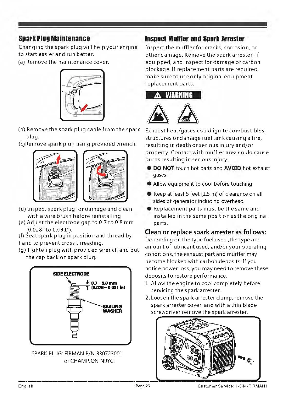
Spark
Plug
Mainumanca
Changing
the
spark
plug
will
help
your
engine
to
start
easier
and
run
better.
(a)
Remove
the
maintenance
cover.
IDSPBCI
MUfllBr
and
Spark
ArrBSIBr
Inspect
the
muffler
for
cracks,
corrosion
,
or
other
damage.
Remove
the
spark
arrester,
if
equipped,
and
inspect
for
damage
or
carbon
blockage.
If
replacement
parts
are
required,
make
sure
to
use
only
original
equipment
replacement
parts.
A
WARNING
(b) Remove
the
spark
plug
cable
from
the
spark
Exhaust
heat/gases
could
ignite
combustibles,
plug.
structures
or
damage
fuel
tank
causing
a
fire,
(c)Remove
spark
plur_i
using
provided
wrench.
~
-
-~•
~
. ,l!
- ~
(d)
Inspect
spark
plug
for
damage
and
clean
with
a
wire
brush
before
reinstalling
(e)
Adjust
the
electrode
gap
to
0.7
to
0.8
mm
(0.028"
to
0.031").
(f)
Seat
spark
plug
in
position
and
thread
by
hand
to
prevent
cross
threading.
(g)
Tighten
plug
with
provided
wrench
and
put
the
cap
back
on
spark
plug.
SIDE
ELECTIIODE
SEALING
WASHER
SPARK
PLUG:
FIRMAN P/N 330723001
or
CHAMPION
N9YC.
resulting
ind
eath
or
serious
injury
and/or
property.
Contact
with
muffler
area
could
cause
burns
resulting
in
serious
injury.
e
DO
NOT
touch
hot
parts and
AVOID
hot
exhaust
gases.
•
Allow
equipment
to
cool before touching.
• Keep at least 5 feet (LS m)
of
clearance on all
sides
of
generator including overhead.
•
Replacement
parts
must
be
the
same
and
installed
in
the
same
position
as
the
original
parts.
Clean
or
replace
spark
arrester
as
follows:
Depending
on
the
type
fuel used
,the
type
and
amount
of
lubricant
used,
and/or
your
operating
conditions,
the
exhaust
part
and
muffler
may
become
blocked
with
carbon
deposits.
If
you
notice
power
loss,
you
may
need
to
remove
these
deposits
to
restore
performance.
1.
Allow
the
engine
to
cool
completely
before
servicing
the
spark
arrester.
2. Loosen
the
spark
arrester
clamp,
remove
the
spark
arrester
cover,
and
with
a
thin
blade
screwdriver
remove
the
spark
arrester.
English
Page
29
Customer
Service
1-844-FIRMAN
1
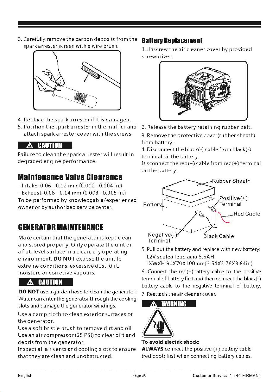
3.
Carefully
remove
the
carbon
deposits
from
the
Batterv
Replacement
spark
arrester
screen
with
a
wire
brush.
4.
Replace
the
spark
arrester
if
it
is
damaged.
LU
nscrew
the
air
cleaner
cover
by
provided
screwdriver.
5.
Position
the
spark
arrester
in
the
muffler
and
2. Release
the
battery
retaining
rubber
belt.
attach
spark
arrester
cover
with
the
screws.
A
CAUTION
Fa
ii u
re
to
clean
the
spark
arrester
wi
II
res u
It
in
degraded
engine
performance.
Maintenance
Valve
Clearance
-
Intake:
0.06
- 0.12
mm
(0.002 -
0.004
in.)
- Exhaust:
0.08
-
0.14
mm
(0.003 - 0.005 in.)
To
be
performed
by
knowledgable/experienced
owner
or
by
authorized
service
center.
GENERATOR
MAINTENANCE
Make
certain
that
the
generator
is
kept
clean
and
stored
properly.
Only
operate
the
unit
on
a
flat,
level
surface
in
a clean,
dry
operating
environment.
DO
NOT
expose
the
unit
to
extreme
conditions,
excessive
dust,
di
rt,
moisture
or
corrosive
vapours.
&.
CAUTION
DO
NOT
use a garden hose
to
clean
the
generator.
Water
can
enter
the
generatorthrough
the cooling
slots and damage
the
generator
windings.
Use a
damp
c
loth
to
clean
exterior
surfa
c
es
of
the
generator.
Use a
soft
bristle
brush
to
removed
irt
and
oil.
Use an
air
compressor
(25 PSI)
to
clear
dirt
and
debris
from
the
generator.
Inspect
all
air
vents
and
cooling
slots
to
ensure
that
they
are clean
and
unobstructed.
3.
Remove
the
protective
cover(rubber
sheath)
from
battery.
4.
Disconnect
the
black(-) cable
from
black(-)
terminal
on
the
battery.
Disconnect
the
red
(+)cable
from
red (+)
terminal
on
the
battery.
Battery
Red
Cable
5.
Pull
out
the
battery and replace
with
new
battery:
12V
sealed lead acid 5.5AH
LXWXH:90X70X100mm(3.54X2.76X3.84in)
6.
Connect
the
red (+)battery cable
to
the positive
terminal
of
battery first and then connect
the
black(-)
battery cable
to
the
negative terminal
of
battery.
7.
Reattach
the
air cleaner cover.
&.
WARNING
To
avoid
electric shock:
ALWAYS connect
the
positive(
+) battery cable
(red boot) first when connecting battery cables.
English
Page
30
Customer
Servic
e 1 -844
-FIRMAN
1
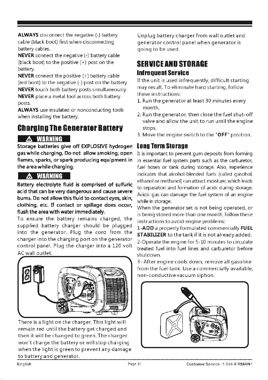
ALWAYS disconnect
the
negative(-) battery
cable (black boot) first
when
disconnecting
battery cables.
NEVER connect
the
negative (-) battery cable
(black boot)
to
the
positive ( +) post
on
the
battery.
NEVER connect
the
positive ( +) battery cable
(red boot)
to
the
negative (-) post on
the
battery.
NEVER touch both battery posts simultaneously.
NEVER place a metal
tool
across
both
battery
posts.
ALWAYS use insulated
or
nonconducting tools
when installing
the
battery.
Charging
The
Generator
Batterv
A
WARNING
Storage batteries give
off
EXPLOSIVE hydrogen
gas while charging. Do
not
allow smoking, open
flames, sparks,
or
spark producing
equipment
in
the
area while charging.
&
WARNING
Battery electrolyte fluid
is
comprised
of
sulfuric
acid that can be very dangerous and cause severe
burns.
Do
not
allow this fluid
to
contact eyes, skin,
clothing, etc.
If
contact
or
spillage does occur,
flush the area with water immediately.
To
ensure
the
battery
remains charged,
the
supplied
battery
charger
should
be
plugged
into
the
generator.
Plug
the
cord
from
the
charger
into
the
charging
port
on
the
generator
control
panel. Plug
the
charger
into
a
120
volt
AC
wall
outlet.
There
is
a
light
on
the
charger.
This
light
will
remain
red
until
the
battery
get
charged
and
then
it
will
be
changed
to
green.
The
charger
won't
charge
the
battery
or
will
stop
charging
when
the
light
is
green
to
prevent
any
damage
to
battery
and
generator.
Unplug
battery
charger
from
wall
outlet
and
generator
control
panel
when
generator
is
going
to
be
used.
SERVICE
AND
STORAGE
lnlrequent
Service
If
the
unit
is
used
infrequently,
difficult
starting
may
result.
To
eliminate
hard
starting,
follow
these
instructions:
1. Run
the
generator
at
least
30
minutes
every
month.
2.
Run
the
generator,
then
closet
he fuel
shut-off
valve
and
allow
the
unit
to
run
until
the
engine
stops.
3.
Move
the
engine
switch
to
the
"OFF"
position.
long
Term
Storage
It
is
important
to
prevent
gum
deposits from forming
in essential fuel system parts such
as
the carburetor,
fuel
hoses
or
tank during storage. Also, experience
indicates that alcohol-blended fuels
(called
gasohol,
ethanol
or
methanol)
can
attract moisture, which
leads
to
separation and formation
of
acids during storage.
Acidic gas
can
damage the fuel system
of
an
engine
while in storage.
When
the
generator
set
is
not
being operated,
or
is being stored
more
than
one
month,
follow
these
instructions
to
avoid engine problems:
1-ADD
a
properly
formulated
commercially
FUEL
STABILIZER
to
the
tank
if it
is
not
already
added.
2-Operate
the
engine
for
5-10 minutes
to
circulate
treated fuel
into
fuel lines and
carburetor
before
shutdown.
3-
After
engine
cools
down,
remove
all
gasoline
from
the
fuel
tank.
Use a
commercially
available,
non-conductive
vacuum
siphon.
English
Page 31
Customer
Service
1-844-FIRMAN
1
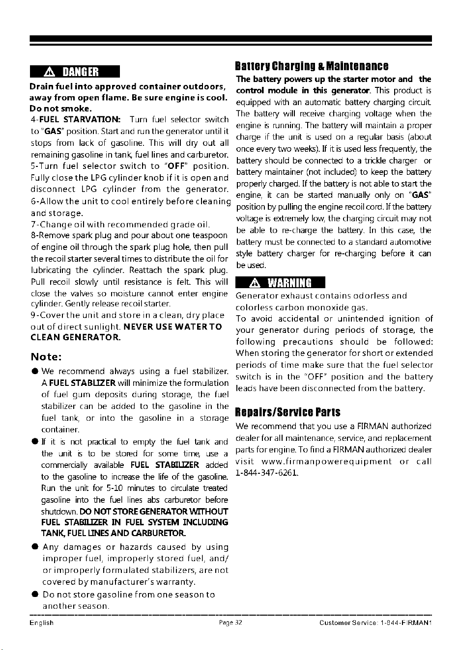
.1l.
DANGER
Drain
fuel
into
approved
container
outdoors,
away
from
open
flame.
Be
sure
engine
is
cool.
Do
not
smoke.
4-FUEL STARVATION: Turn fuel selector switch
Batterv
Charging
&
Maintenance
The battery powers
up
the starter
motor
and the
control module
in
this generator. This product
is
equipped with
an
automatic battery charging circuit
The battery will receive charging voltage when the
engine
is
running. The battery will maintain a proper
charge
if
the unit
is
used
on a regular
basis
(about
once every
two
weeks).
If
it
is
used
less
frequently, the
battery should be connected
to
a trickle charger
or
battery maintainer (not included)
to
keep the battery
properly charged.
If
the battery
is
not able
to
start the
to
"GAS"
position. Start and run
the
generator until
it
stops
from
lack
of
gasoline. This will
dry
out
all
remaining gasoline in tank, fuel lines and carburetor.
5-Turn
fuel
selector
switch
to
"OFF"
position.
Fully
close
the
LPG
cylinder
knob
if
it
is
open
and
disconnect
LPG
cylinder
from
the
generator.
engine, it
can
be started manually only on
"GAS"
6-Allow
the
unit
to
cool
entirely
before
cleaning
position by pulling the engine recoil cord.
If
the battery
and
storage.
voltage
is
extremely
low,
the charging circuit may
not
7-Change
oil
with
recommended
grade
oil.
be
able
to
re-charge the battery. In this
case,
the
8-Remove spark plug and
pour
about
one teaspoon
battery must
be
connected
to
a standard automotive
of
engine oil
through
the
spark plug hole, then pull
the
recoil starter several times
to
distribute the oil
for
style battery charger for re-charging before it
can
lubricating
the
cylinder. Reattach
the
spark plug.
Pull recoil slowly until resistance
is
felt. This will
close
the
valves so moisture cannot
enter
engine
cylinder. Gently release recoil starter.
9-Cover
the
unit
and
store
in
a
clean,
dry
place
out
of
direct
sunlight.
NEVER
USE
WATER TO
CLEAN GENERATOR.
Note:
be
used.
&
WARNING
Generator
exhaust
contains
odorless
and
colorless
carbon
monoxide
gas.
To avoid
accidental
or
unintended
ignition
of
your
generator
during
periods
of
storage,
the
following
precautions
should
be
followed:
When
storing
the
generator
for
short
or
extended
periods
of
time
make
sure
that
the
fuel
selector
• We recommend always using a fuel stabilizer.
switch
is
in
the
"OFF"
position
and
the
battery
A
FUEL
STABLlZER
will minimize
the
formulation
leads have been
disconnected
from
the
battery.
of
fuel
gum
deposits
during
storage,
the
fuel
stabilizer can be added
to
the
gasoline in
the
Repairs/Service
Parts
fuel tank,
or
into
the
gasoline in a storage
container.
• If it
is
not practical
to
empty the
fuel
tank and
the unit
is
to
be
stored for some time,
use
a
We recommend
that
you
use a FIRMAN authorized
dealer
for
all maintenance, service, and replacement
parts
for
engine. To find a FIRMAN authorized dealer
commercially available
FUEL
STABILIZER
added
visit
www.firmanpowerequipment
or
call
to
the gasoline
to
increase
the life
of
the gasoline.
1
-
844
-
347
-
626
1.
Run
the unit for 5-10 minutes
to
circulate treated
gasoline into the fuel
lines
abs
carburetor before
shutdown.
DO
NOT
SlORE
GENERATOR
WITHOUT
FUEL
STABILIZER
IN
FUEL
SYSTEM
INCLUDING
TANK.
FUEL
UNES
AND
CARBURETOR.
•
Any
damages
or
hazards
caused
by
using
improper
fuel,
improperly
stored
fuel,
and/
or
improperly
formulated
stabilizers,
are
not
covered
by
manufacturer's
warranty.
•
Do
not
store
gasoline
from
one
season
to
another
season.
English
Page
32
Customer
Service: 1-844-FIRMAN1
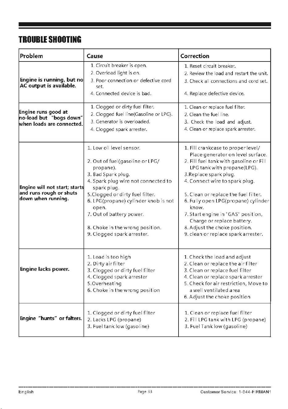
TROUBLE
SHOOTING
Problem Cause Correction
1.
Ci
r
cuit
breaker is open.
1. Reset cir
cuit
breaker.
2.
Overload
light
is on.
2.
Review
the
load and restart
the
unit.
Engine
is
running,
but
no
3.
Poor connection
or
defective cord
3.
Check all connections and cord set.
AC
output
is
available.
set.
4. Connected device is bad. 4. Replace defective
dev
i
ce.
1. Clogged
or
dirty
fuel filter.
1.
Clean
or
re
place fuel filter.
Engine runs good
at
2.
Clogged fuel line(Gasoline
or
LPG).
2.
Clean
the
fuel
l"ine.
no-load
but
"bogs down"
3.
Gener
ato
r
is
overloaded.
3. Check
the
load and adjust.
lwhen
loads are connected.
4. Clogged spark arrester.
4.
Clean
or
re
place spark arrester.
1.
Low
oil
level
sensor.
1. Fill
cran
kcase
to
pro
p
er
level/
Place
generator
on
level
surface.
2.
Out
of
fuel(gasoline
or
LPG/ 2. Fill
fuel
tank
with
gaso
l
ine
or
Fill
propane).
LPG
tank
with
propane(LPG).
3. Bad
Spark
pl
ug.
3.Replace
spark
plug.
4. Spark
plug
wire
not
connected
to
4.
Connect
wire
to
spa
rk
plug.
Engine will not start; start,
spark
plug.
and runs rough
or
shuts
5.Clogged
or
dirty
fuel
fi
l
ter.
5.
Clean
or
replace
the
fuel
fi
l
ter.
down when running.
6. LPG(pr
opane)
cylinder
knob
is
not
6.
Fully
open
LPG(propane
)
cylinder
open.
know.
7.
Out
of
battery
powe
r.
7.
Start
engine
in
"GAS"
position,
Char
ge
or
r
eplace
battery.
8.
Choke
in
the
wrong
position.
8.
Adjust
t he
choke
position.
9.
Clogged
spark
ar
r
ester.
9.
clean
o r
rep
I
ace
spa rk arr
ester.
1. Load
is
too
high
1.
Check
the
load
and
adjust
2.
Dirty
ai
r
filter
2.
Clean
o r r
eplace
the
ai
r
filte
r
Engine lacks
power.
3.
Clogged
or
di
r
ty
fuel
fi
lte
r 3.
Clean
o r
replace
fuel
fi
l
ter
4.
Clogged
spark
ar
rester
4.
CI
ean
or
replace
spark
ar
r
este
r
5.Overheating
5.
Check
for
air
restrict
ion,
Move
to
6.
Choke
in
the
wrong
position
a
well
ventilated
area
6.
Adjust
the
choke
posit
i
on
1.
Clogged
or
di
r
ty
fuel
fi
lter
1. Clean
or
replace
fuel
filter
Engine "hunts" or falters.
2. Lacks
LPG
(propane)
2. Fill
LPG
tank
with
LPG
(pr
opane)
3. Fuel
tank
low
(gasoline)
3. Fuel T
ank
l
ow
(gasoline)
English
Pa
ge
33
Customer
Servic
e 1
·844
·FIRMAN
1
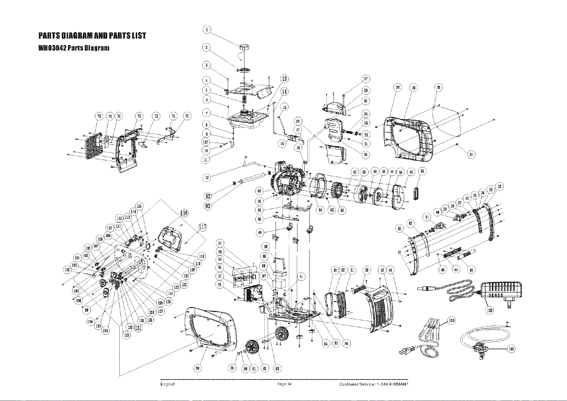
PARTS
DIAGRAM
AND
PARTS
UST
WII03042
Paris
Diagram
(76
1
/iY?4'1
\--)
\~
_
_/
"-;-/
I I I
' I I
,-F
Englisl1
Page
3'1
(i;
',--/
I
I
I
I
I
I
Customer
Service: 1-S44-F-:RMAN1
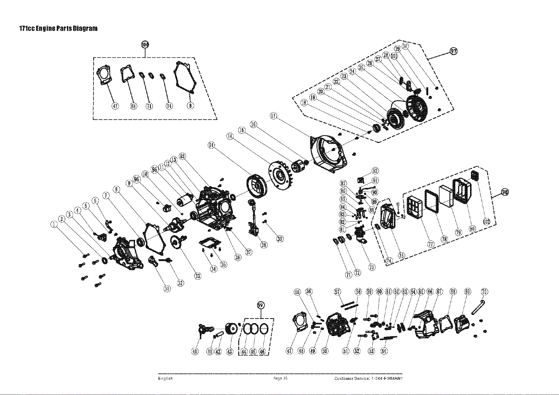
171cc
Engine
Parts
Diagram
,P
,P
,P
Englisl1
,.
Page
35
Customer
Service: 1-S44-F-:RMAN1
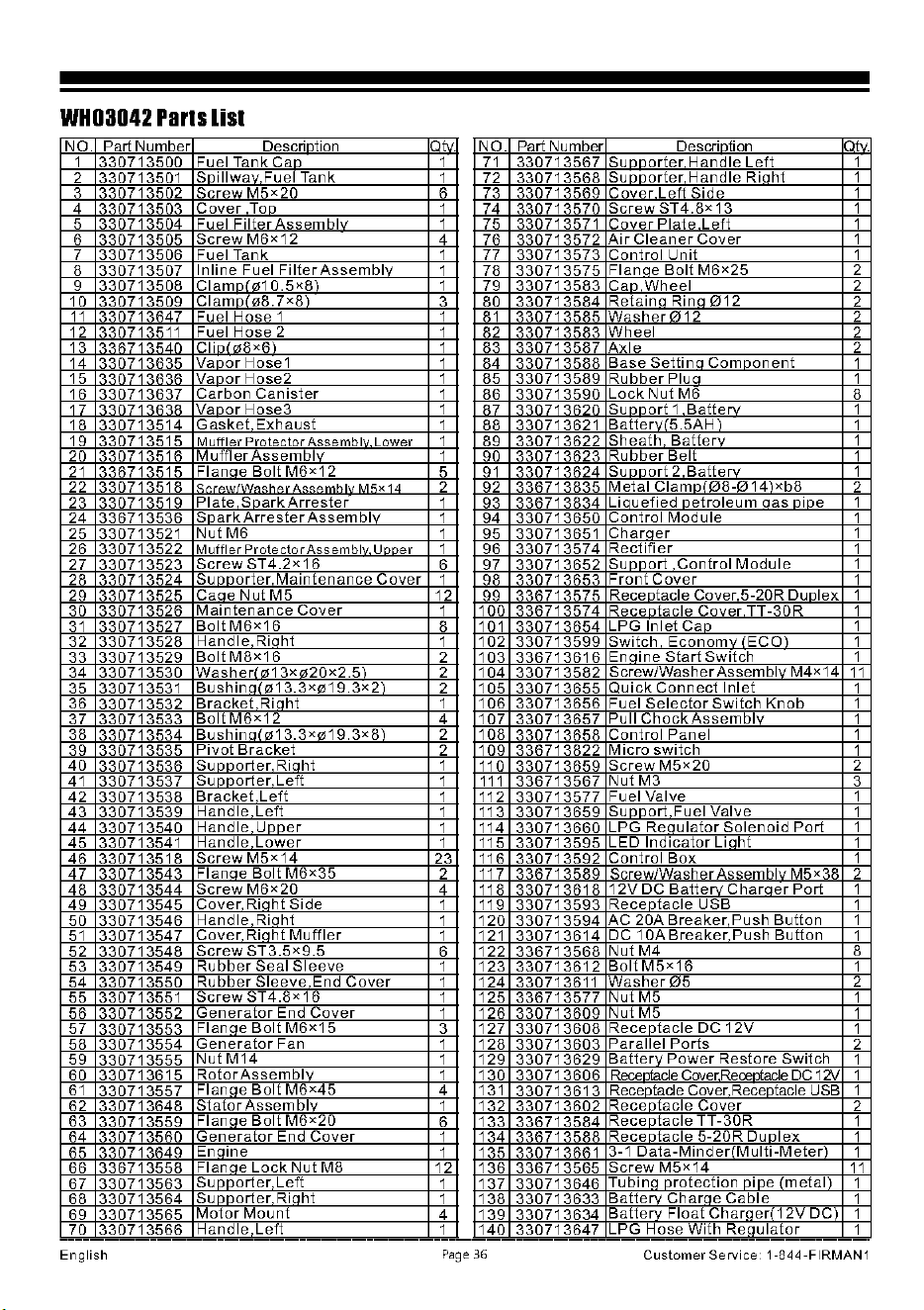
WHD3042
Parts
list
NO. Part Number
Descrintion
1 330713500
Fuel Tank Can
2 330713501
Snillwav.Fuel
Tank
3 330713502
Screw
M5x2Q
4 330713503
Cover
Too
5 330713504 Fuel
Filter
Assembl
6 330713505
ScrewM6x12
7 330713506 Fuel Tank
8 330713507
In
line Fuel
Filter
Assemblv
9 330713508
Clam
10.5x8l
10 330713509
Clamnl08.7x8\
11
330713647 Fuel Hose 1
12 330713511
Fuel Hose 2
13 Cli
8<6
14 330713635
Vanor
Hose1
15
Vanor
Hose2
16 330713637
Carbon
Canister
17
Vanor
Hose3
18 330713514
Gasket
Exhaust
19 330713515
Muffler
Protector
Assemblv
Lower
20 330713516
Muffler
Assemblv
21
336713515
Flanae
Bolt
M6x12
22 330713518
""
23 330713519
Plate
SnarkArrester
24 336713536
S
ark
Arrester
Assemblv
25 330713521
Nut
M6
26 330713522
Muffler
Protector
Assemblv
Unner
27 330713523
ScrewST4.2x16
28
330713524
Sc
orter
Maintenance
Cover
29
330713525
Caae
Nut
M5
30
330713526
Maintenance
Cover
31
330713527
Bolt
M6x16
32
330713528
Handle
Rinht
33
330713529
Bolt
M8x16
34
330713530
Washer(
m13xm20x2.5l
35 330713531
Bush
in
a/
013.3x019.3x2\
36
330713532
Bracket
Riaht
37
330713533
Bolt
M6x12
38
330713534
Bush
in
a(
013.3x019.3x8
l
39
330713535
Pivot
Bracket
40
330713536
Sc
orter
Rinht
41
330713537
Sc
orter
Left
42
330713538
Bracket
Left
43
330713539
Handle
Left
44
330713540
Handle
U
e,
45 330713541
Handle
Lower
46
330713518
ScrewM5x14
47
330713543
Flanne
Bolt
M6x35
48
330713544
Screw
M6x20
49
330713545
Cover
Rinht Side
50
330713546
Handle
Rinht
51
330713547
Cover
Riaht
Muffler
52
330713548
Screw
ST3.5x9.5
53
330713549
Rubber
Seal
Sleeve
54
330713550
Rubber
Sleeve
End
Cover
55 330713551
ScrewST4.8x16
56
330713552
Generator
End
Cover
57
330713553
Flan e
Bolt
M6x15
58
330713554
Generator
Fan
59
330713555
Nut
M14
60
330713615
Rotor
Assemblv
61
330713557
Flanae
Bolt
M6x45
62
330713648
Stator
Assemblv
63
330713559
Flanae
Bolt
M6x20
64
330713560
Generator
End
Cover
65
330713649
En
ine
66
336713558
Flan e
Lock
Nut
M8
67
330713563
Sc
orter
Left
68
330713564
Sc
orter
Riaht
69
330713565
Motor
Mount
70
330713566
Handle
Left
- - - - -
English
1
1
6
1
1
4
1
1
1
3
1
1
1
1
1
1
1
1
1
1
5
2
1
1
1
1
6
1
12
1
8
1
2
2
2
1
4
2
2
1
1
1
1
1
1
23
2
4
1
1
1
6
1
1
1
1
3
1
1
1
4
1
6
1
1
12
1
1
4
1
- -
NO. Part Number Descrintion 1t".
71
330713567
Su
orter
Handle
Left
1
72
330713568
Su
orter
Handle
Riaht
1
73
330713569
Cover
Left
Side
1
74
330713570
ScrewST4.8x13
1
75 330713571
Cover
Plate
Left
1
76
330713572
Air
Cleaner
Cover
1
77
330713573
Control
Unit 1
78
330713575
Flanne
Bolt
M6x25
2
79
330713583
Can
Wheel
2
80
330713584
Retain a Rina
012
2
81
330713585
Washer012
2
82
330713583
Wheel
2
83
330713587
Axle
2
84
330713588
Base
Settinn
Comnonent
1
85
330713589
Rubber
Plun
1
86
330713590
Lock
Nut
M6 8
Su
ort
1
Batterv
1
88
330713621
Battervl5.5AH
l 1
89
330713622
Sheath
Batterv
1
90
330713623
Rubber
Belt
1
91
330713624
Su
ort
2
Batterv
1
92
336713835
Metal
Clamn108-014
xb8 2
93
336713834
Linuefied
netroleum
nas
nine
1
94
330713650
Control
Module
1
95
330713651
Charner
1
96
330713574
Rectifier
1
97
330713652
Su ort
Control
Module
1
98
330713653
Front
Cover
1
99
336713575
Receotacle Cover 5-20R
Duolex
1
100
336713574
Recentacle
CoverTT-30R
1
101
330713654
LPG Inlet Can 1
102
330713599
Switch
Economv
ECO 1
103
336713616
En
nine
Start
Switch
1
104
330713582
Screw/WasherAssemblvM4x14
11
105
330713655
Quick
Connect
Inlet
1
106
330713656
Fuel
Selector
Switch
Knob
1
107
330713657
Pull
ChockAssemblv
1
108
330713658
Control
Panel
1
109
336713822
Micro
switch
1
110
330713659
ScrewM5x20
2
111
336713567
NutM3
3
112
330713577
Fuel Valve 1
113
330713659
Su ort Fuel
Valve
1
114
330713660
LPG
ReaulatorSolenoid
Port
1
115
330713595
LED
lndicatorLiaht
1
116
330713592
Control
Box
1
117
336713589
Screw/Washer
Assembl"
M5x38
2
118
330713618
12VDC
BattentCharnerPort
1
119
330713593
Recentacle
USB 1
120
330713594
AC 20A
Breaker
Push
Button
1
121
330713614
DC 1
OABreaker
Push
Button
1
122
336713568
Nut
M4 8
123
330713612
Bolt
M5x16
1
124
330713611
Washer05
2
125
336713577
Nut
M5 1
126
330713609
Nut
M5 1
127
330713608
Recentacle
DC
12V
1
128
330713603
Parallel
Ports
2
129
330713629
Batterv
Power
Restore Switch 1
130
330713606
Rece
cle
CoverRecentacle
DC
1'N
1
131
330713613
Recentacle Cover Recentacle
USB
1
132
330713602
Receotacle
Cover
2
133
336713584
Receotacle
TT-30R
1
134
336713588
Recentacle
5-20R
Dunlex
1
135
330713661
3-1
Data-Minder
Multi-Meter1 1
136
336713565
ScrewM5x14
11
137
330713646
Tubina
nrotection
nine
/metal\
1
138
330713633
Batterv
Charae
Cable
1
139
330713634
Batterv
Float
Charaer!
12V
DC 1
140
330713647
LPG Hose With
Reaulator
1
-
--
-
--
-
Page
36
Customer
Service: 1-844-FIRMAN1
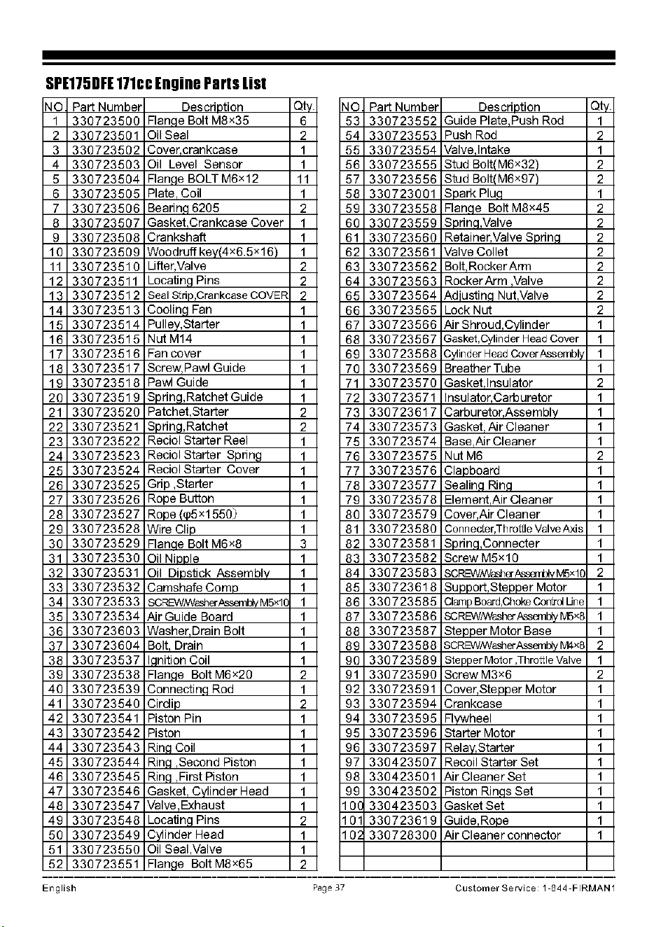
SPE175DH
171cc
Engine
Parts
list
NO
Part Number
Descrintion
Qtv.
NO
Part Number
Descrintion
Qtv.
1
330723500
Flanae Bolt M8x35
6 53
330723552
Guide Plate Push Rod
1
2 330723501
Oil Seal
2 54
330723553
Push Rod
2
3
330723502
Cover crankcase
1 55
330723554
Valve Intake
1
4
330723503
Oil Level Sensor
1 56
330723555
Stud
Bolt/M6x32\
2
5
330723504
Flanae BOLT M6x12
11
57
330723556
Stud
Bolt/M6x97\
2
6
330723505
Plate Coil
1 58 330723001
Spark
Plua
1
7
330723506
Bearina 6205
2 59
330723558
Flanae Bolt M8x45
2
8
330723507
Gasket Crankcase Cover
1 60
330723559
Sorina.Valve
2
9
330723508
Crankshaft
1
61
330723560
Retainer Valve Snrina
2
10
330723509
Woodruff kev(4x6.5x16)
1 62 330723561
Valve Collet
2
11
330723510
Lifter,Valve
2 63
330723562
Bolt Rocker Arm
2
12 330723511
Locatina Pins
2 64
330723563
Rocker Arm Valve 2
13
330723512
Seal strio,Crankcase COVER
2 65
330723564
Adiustina Nut Valve
2
14
330723513
Coolina
Fan
1 66
330723565
Lock Nut 2
15
330723514
Pullev,Starter
1 67
330723566
Air Shroud Cvlinder
1
16
330723515
Nut
M14
1 68
330723567
Gasket,Cylinder Head Cover
1
17
330723516
Fan
cover
1 69
330723568
Cv1inder Head CoverAssemblv
1
18
330723517
Screw,Pawl Guide
1 70
330723569
Breather Tube 1
19
330723518
Pawl Guide
1
71
330723570
Gasket Insulator 2
20
330723519
Sprina,Ratchet Guide
1 72
330723571 Insulator Carburetor 1
21
330723520
Patchet,Starter
2 73
330723617
Carburetor Assemblv
1
22
330723521
Sprinq,Ratchet
2 74
330723573
Gasket, Air Cleaner
1
23
330723522
Reciol Starter Reel
1 75
330723574
Base Air Cleaner 1
24
330723523
Reciol Starter Sprinq
1 76
330723575
Nut
M6
2
25
330723524
Reciol Starter Cover
1 77
330723576
Clanboard
1
26
330723525
Grip ,Starter
1 78
330723577
Sealina Rina 1
27
330723526
Rope Button
1 79
330723578
Element Air Cleaner 1
28
330723527
Rope /w5x1550)
1 80
330723579
Cover,Air Cleaner
1
29
330723528
Wire Clin
1
81
330723580
Connecier,Throttle Valve
Axis
1
30
330723529
Flanae Bolt M6x8
3 82
330723581 Sorina,Connecter 1
31
330723530
OilNinnle
1 83
330723582
Screw
M5x1Q
1
32
330723531
Oil Diostick Assemblv 1 84
330723583
SCREI/\/Mfasherli~,M5x1Q
2
33
330723532
Camshafe Cornn
1 85
330723618
Sunnort Stenner Motor
1
34
330723533
SCREI/\/Mlasher ftssemttv M5x10
1 86
330723585
Clamp Board,Choke Confrd Line
1
35
330723534
Air Guide Board 1 87
330723586
SCREl/\/!Washer
ftssemH>,
M5x8
1
36
330723603
Washer Drain Bolt
1 88
330723587
Stenner Motor Base
1
37
330723604
Bolt Drain
1 89
330723588
SCREI/\/IWasherAssemH>
1
M4x8
2
38
330723537
lanition Coil
1 90
330723589
Stenner
Motor
,Throttle Valve
1
39
330723538
Flanae Bolt M6x2Q
2
91
330723590
ScrewM3x6
2
40
330723539
Connectina Rod
1
92 330723591
Cover,Stenner Motor
1
41
330723540
Cirdin
2
93
330723594
Crankcase 1
42 330723541 Piston Pin
1
94
330723595
Flvwheel
1
43
330723542
Piston
1
95
330723596
Starter Motor 1
44
330723543
Rina Coil
1
96
330723597
Relav,Starter
1
45
330723544
Rina Second Piston
1
97
330423507
Recoil Starter Set 1
46
330723545
Rina First Piston
1
98 330423501 Air Cleaner Set 1
47
330723546
Gasket Cvlinder Head
1
99
330423502
Piston Rinas Set
1
48 33072354 7
Valve,Exhaust
1
101
330423503
Gasket Set 1
49
330723548
Locatina Pins
2
101
330723619
Guide Rone
1
50
330723549
Cylinder Head
1
1 O'
330728300
Air Cleaner connector 1
51
330723550
Oil
Seal,Valve
1
52 330723551
Flanqe Bolt M8x65
2
English
Page
37
Customer
Service: 1-844-FIRMAN1
SERVICE
INFORMATION
CONTACT
THE
FIRMAN
PRODUCT
SERVICE
DEPARTMENT
AT
1-844-347-6261
or
at
www.
fi
rma
npowereq
ui
pment.com
to
obtain
warranty
service
information
or
to
order
replacement
parts
or
accessories.
HOW
TO
ORDER
REPlACEMENT
PARTS
Even
quality built equipment
such
as
the electric
generator
you
have purchased
might
need
occasional replacement parts
to
maintain
it
in
good
condition
over
the
years. To
order
replacement parts, please give the following
information:
WARRANTY
FIRMAN
Three
131
Year
limited
Warrantv
Warranty Qualifications
FIRMAN
GENERATOR
wil I registerthe warranty u pan
receipt
of
your Warranty Registration
Card
and a
copy
of
your
sales receipt from one
of
FIRMAN's
retail locations
as
proof
of
purchase. Please
submit
yourwarranty
registration and
your
proof
of
purchase
within ten
(10)
days
of
the date
of
purchase.
Repair/Replacement
Warranty
FIRMAN
warrants
to
the
orig
in al
purchaser
that
the
mechanical
and
electrical
components
will
be
free
of
defects
in
material
and
workmanship
for
a
period
of
one
(1)
year
(parts
and
labor)
and
three
(3) years
(parts)
from
the
orig
in al
date
of
purchase
90 days
[parts
and
labor]
and
180
days
[parts]
for
commercial
&
industrial
use.
Transportation
charges
on
product
submitted
for
repair
or
replacement
under
this
warranty
are
the
sole
responsibility
of
the
purchaser.
This
warranty
only
applies
to
the
original
purchaser
and
is
not
transferable.
1.
Model
No.
,Rev. Level and Serial
No.
and all
Do
Not
Return
the
Unit
to
the
Place
specifications
shown
on
the
Model
No./Serial
of
Purchase
No.
plate.
Contactthe
FIRMAN Service
Center
and
FIRMAN
2.
Parts
number
or
numbers
as
shown
in
the
Parts List
section.
3.
A
brief
description
of
the
trouble
with
the
generator.
( REGISTER
YOUR
PRODUCT)
Register
your
Firman
generator
on
Ii
ne
at
www.firmanpowerequipment.com
will
troubleshoot
any issue via
phone
ore-mail.
If
the
problem
is
not
corrected
by
this
method,
FIRMAN
will,
at
its
option,
authorize
evaluation,
repair
or
replacement
of
the
defective
part
or
component
at
a FIRMAN Service
Center.
FIRMAN
will
provide
you
with
a case
number
for
warranty
service. Please
keep
it
for
future
reference.
Repairs
or
replacements
without
prior
authoriz
-ation,
or
at
an
unauthorized
repair
facility,
will
not
be
covered
by
this
warranty.
Warranty
Exclusions
This
warranty
does
not
cover
the
following
repairs
and
equipment:
Normal
Wear
Your
product
needs
periodic
parts
and
service
to
perform
well.
This
warranty
does
not
cover
repair
when
normal
use
has
exhausted
the
life
of
a
part
or
the
equipment
as
a
whole.
English
Page
38
Customer
Service: 1-844-FIRMAN1
Installation, Use and Maintenance
This
warranty
will
not
apply
to
parts
and/or
labor
if
your
product
is
deemed
to
have
been
misused,
neglected,
involved
in
an
accident,
abused,
loaded
beyond
the
generator's
limits,
modified,
installed
improperly
or
connected
incorrectly
to
any
electrical
component.
Normal
maintenance
is
not
covered
by
this
warranty.
Other Exclusions
This
warranty
excludes:
-
cosmetic
defects
such as
paint,
decals,
etc.
-
wear
items
- accessory parts
-failures
due
to
acts
of
God
and
other
force
majeure
events
beyond
the
manufacturer's
control
-
problems
caused
by
parts
that
are
not
original
FIRMAN
parts
-
units
used
for
prime
power
in
place
of
existing
utility
power
where
utility
is
present
or
in
place
of
utility
power
where
utility
power
service
does
not
normally
exist.
Limits
of
Implied Warranty and
Consequential Damage
FIRMAN disclaims any obligation to cover any
loss
of
time, use
of
this product, freight,
or
any
incidental or consequential claim by anyone
from using this product. THIS WARRANTY IS
IN
LIEU
OF
ALL
OTHER WARRANTIES,
EXPRESS
OR
IMPLIED,
INCLUDING
WARRANTIES
OF
MERCHANTABILITY
OR
FITNESS
FOR A
PARTICULAR
PURPOSE.
A
unit
provided
as
an
exchange will
be
subject
to
the
warranty
of
the
original unit. The length
of
the
warranty governing
the
exchanged unit
will remain calculated by reference
to
the
purchase date
of
the
original unit.
This
warranty
gives
you
certain
legal
rights
which
may
change
from
state
to
state.
Your
state
may
also
have
other
rights
you
may
be
entitled
to
that
are
not
listed
within
this
warranty.
Contact
Information
You
may
contact Fl
RMAN
at:
Address
Firman
Power
Equipment
Attn:
Customer
Service
8716
West
Ludlow
Dr.
Suite
#6
Peoria,
AZ
85381
www.fi
rma
npowereq
uipment.com
IM!
are
RRMAN POWER• And 1-.e
ate
here
for)OU.
Gustomer
SeMce Desk•
1..lJ44..347~261(1-844-RRMAN1)
ten
PST(9am
EST)
until
8pm
EST(Spm
PST)
TechnicalSeMceDesk-1-844--347~261(1-844-FIRMAN1)
ten
PST(9am
EST)
until
8pm
EST(Spm
PST)
2417
Tech
Support·
1-844--347~61(1-844-FIRMAN1)
English
Page
39
Customer
Service
1 -844
-FIRMAN
1
FIRMAN
POWER
EQUIPMENT
INC.
Emission
Control
System
Warranty
CALIFORNIA
AND
FEDERAL EXHAUST
AND
EVAPORATIVE EMISSIONS CONTROL WARRANTY STATEMENT
YOUR WARRANTY RIGHTS
AND
OBLIGATIONS
The
California
Air
Resources
Board,
US
Environmental
Protection
Agency
("US
EPA") and
FIRMAN
POWER
EQUIPMENT
INC.(FIRMAN)
are
pleased
to
explain
the
emissions
control
systems
warranty
on
your
2021-2022
or
later
Small
Off-Road
Engine
("SORE")
and
engine
powered
equipment.
In
California,
new
equipment
that
use
small
off-road
engines
must
be
designed,
built
and
equipped
to
meet
the
State's
stringent
anti-smog
standards.
FIRMAN
must
warrant
the
emissions
control
systems
on
your
SORE
and
engine
powered
equipment
for
the
periods
of
time
listed
below
provided
there
has
been
no
abuse,
neglect
or
improper
maintenance
of
your
small
off-road
engine
or
equipment
leading
to
the
failure
of
the
emissions
control
system.
Your
emissions
control
system
may
include
parts
such
as
the
carburetor
or
fuel-injection
system,
the
ignition
system,
catalytic
converter,
fuel
tanks,
fuel
lines
(for
liquid
fuel
and
fuel
vapors),
fuel
caps,
valves,
canisters,
filters,
clamps
and
other
associated
components.
Also
included
may
be
hoses,
belts,
connectors,
and
other
emission-related
assemblies.
Where
a
warrantable
condition
exists,
FIRMAN
will
repair
your
SORE
and
engine
powered
equipment
at
no
cost
to
you
including
diagnosis,
parts
and
labor.
MANUFACTURER'S
WARRANTY
COVERAGE:
The
exhaust
and
evaporative
emissions
control
system
on
your
small
off-road
engine
and
engine
powered
equipment
is
warranted
for
two
years.
If
any
emissions-related
part
on
your
smal I
off-road
engine
and
engine
powered
equipment
is
defective,
the
pa
rt
wi
II
be
repaired
or
replaced
by
FIRMAN.
OWNER'S
WARRANTY
RESPONSIBILITIES:
As
the
SORE
and
engine
powered
equipment
owner,
you
are
responsible
for
the
performa
nee
of
the
required
maintenance
listed
in
your
owner's
manual.
FIRMAN
recommends
that
you
retain
all
receipts
covering
maintenance
on
your
SORE
and
engine
powered
equipment,
but
FIRMAN
cannot
deny
warranty
coverage
solely
for
the
lack
of
receipts
or
for
your
failure
to
ensure
the
performance
of
al
I
scheduled
maintenance.
As
the
SORE
and
engine
powered
equipment
owner,
you
should
however
be
aware
that
FIRMAN
may
deny
you
warranty
coverage
if
your
small
off-road
engine
or
engine
powered
equipment
ora
part
has
failed
due
to
abuse,
neglect,
or
improper
maintenance
or
unapproved
modifications.
You are
responsible
for
presenting
your
small
off-road
engine
and
engine
powered
equipment
to
a FIRMAN
distribution
center
or
service
center
as
soon
as
the
problem
exists. The
warranty
repairs
shall be
completed
in a
reasonable
amount
oftime,
not
to
exceed
30
days.
If
you
have
any
questions
regarding
your
warranty
rights
and
responsibilities,
you
shou Id
contact
FIRMAN
at
1-844-347-6261
or
FIRMAN
Emission Control Defects
Warranty
Provisions
The
warranty
period
begins on
the
date
the
engine/equipment
is
delivered
to
an
ultimate
purchaser. FIRMAN warrants
to
the
ultimate
purchaser and each subsequent purchaser
that
the
engine
is:
Designed,
built,
and
equipped
so
as
to
conform
with
all
applicable
regulations
adopted
by
the
Air
Resources Board
and
US
EPA;
and
Free
from
defects
in
materials
and
workmanship
that
cause
the
failure
of
a
warranted
part
to
be
identical
in all
material
respects
to
the
part
as
described
in
the
engine
manufacturers
application
for
certification.
The warranty
on
emissions-related
parts is as
follows:
(1)
Any
warranted
part
that
is
not
scheduled
for
replacement
as
required
maintenance
in
the
owner's
manual
supplied,
is
warranted
for
the
warranty
period
stated
above.
If
any
such pa
rt
fai
Is
during
the
period
of
warranty
coverage,
the
part
wi
II
be
repaired
or
replaced
by
FIRMAN
at
no
charge
to
the
owner.
Any
such
part
repaired
or
replaced
under
the
warranty
will
be
warranted
for
the
remaining
warranty
period.
(2)
Any
warranted
part
that
is
scheduled
only
for
regular
inspection
in
the
owner's
manua
I
supplied,
is
warranted
for
the
warranty
period
stated
above.
Any
such
part
repaired
or
replaced
under
warranty
will
be
warranted
for
the
remaining
warranty
period.
(3)
Any
warranted
part
that
is
scheduled
for
replacement
as re
qui
red
maintenance
in
the
owner's
ma
nu
al
supplied,
is
warranted
for
the
period
of
time
prior
to
the
first
scheduled
replacement
point
for
that
part.
If
the
part
fai
Is
prior
to
the
first
scheduled
replacement,
the
part
will
be
repaired
or
replaced
by
FIRMAN
at
no
charge
to
the
owner.
Any
such
part
repaired
or
replaced
under
warranty
wi
II
be
warranted
for
the
remainder
of
the
period
prior
to
the
ti
rst
scheduled
replacement
po
int
for
the
part.
(4) Repair
or
replacement
of
any
warranted
part
under
the
warranty
must
be
performed
at
no
charge
to
the
owner
at
a
warranty
station.
(5)
Notwithstanding
the
provisions
of
Subsection
(4)
above,
warranty
services
or
repairs
must
be
provided
by
FIRMAN
that
are
franchised
to
service
the
subject
engines.
(6) The
owner
must
not
be
charged
for
diagnostic
labor
that
leads
to
the
determination
that
a
warranted
part
is
in
fact
defective,
provided
that
such
diagnostic
work
is
performed
at
a
warranty
station.
(7) FIRMAN is
liable
for
damages
to
other
engine
components
proximately
caused
by
a
failure
under
warranty
of
any
warranted
part.
English
Page 40
Customer
Service:
1-844-FIRMAN
1
(8)
Through
ou
t
the
emissions
warranty
period
de
f
ined
in
Subsection
(b)(2), FIRMAN
will
main
t
ain
a
supply
of
warranted
parts
sufficient
to
meet
the
expec
ted
demand
for
such
parts.
(9)
Any
replacement
pa
rt
may
be
used
in
the
performa
nee
of
any
warranty
main
t enance
or
repairs
and
must
be
provided
without
charge
to
t he
owner.
Such use
will
no
t
reduce
the
warranty
obligations
of
the
manufacturer.
(10)
Add-on
or
modified
parts
that
are
not
exempted
by
the
Air
Resources Board
may
not
be
used.
The
use
of
any
non-exempted
add-on
or
modified
par
t s
by
the
ultima
t e
purchaser
will
be
grounds
ford
isallowing
a
warranty
claim.
The
manufacturer
will
not
be
liable
to
warran
t
failures
of
warranted
parts
caused
by
the
use
of
an
on-exempted
add-on
or
modified
part.
PARTS
COVERED
BY
WARRANTY
Listed
below
are
the
parts
(if
equipped)
covered
by
the
Federal and
California
Emission
Control
System
Warranty.
l.Ignition
system
including:
-
Spark
plug
-Ignition
coil
2.
Fuel
metering
system:
- Fuel
tank
- Fuel cap
- Fuel
lines
(for
liquid
fuel
and
fuel
vapors)
and
related
fittings/clamps
- Fuel
regulator,
carburetor
and
internal
parts.
3.
Catalytic
muffler
assembly
including:
- Exhaust
manifold
-
Catalytic
converter
-
Muffler
gasket
-pulse
valve
Limitations
4.
Air
induction
system
including:
-
lnta
ke
pipe/manifold
-
Air
cleaner
5. Cra nkcase
breather
assembly
in
eludin
g:
-
Breather
connection
tube
6. Fuel
tank
evaporative
emission
control
system
including:
- Purge valves
-
Carbon
canister
- Va
por
hoses and
fit
t
ing/clamps
This
Emiss
ion
Control
System
Warranty
sha II
not
cover
any
of
the
following:
(a}
Con
sequential
damages
such
as
loss
oftime,
in
convenience
, loss
of
use
of
the
engine
or
equipment
,
etc.
(b)
Diagnosis
and
inspection
fees
that
do
not
result
in
eligible
warranty
service
bein
g
performed.
FIRMAN
POWER EQUIPMENT I
NC.
Emai
I:
sup
port@fi
rmanpowerequi
pment.co
m
www.fi
rma
npowe
req
uip
me
nt.co
m
English
Page 41
Customer
Service
1-844-FIRMAN
1

r
Firman
Power
Equipment
Inc.
8716
West
Ludlow
Dr.
Suite
#6
Peoria,
AZ
85381
www.firmanpowerequipment.com
All
righ1B
.....,no,d, /vry
111printing
or unauthorimd
uae
wilhout
Iha
wr111Bn
pannlNIDn
lo
axpraaoly
prohlbllad.
P/N:3307~5~71
Rev
01