
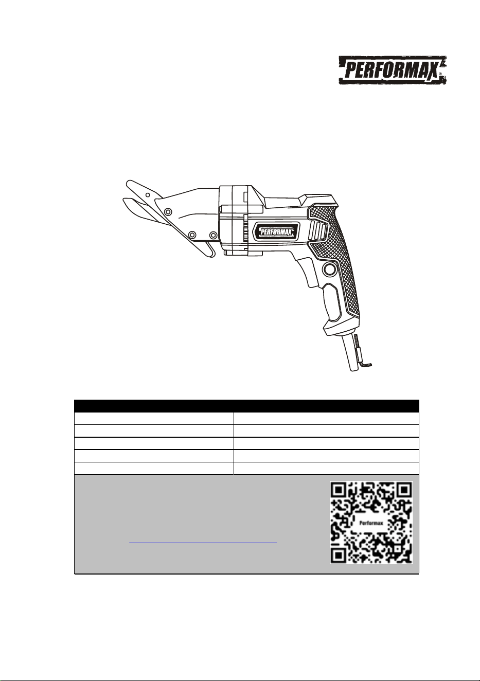
FIBER CEMENT SIDING SHEAR
241-0997
Owner’s Manual
PRODUCT SPECIFICATIONS
Rating: 120 V, 60 Hz, AC
Amperes: 4.8 AMP
Speed: 0-2,700 SPM (no load)
Maximum cutting thickness: 5/16" (8 mm)
Weight: 4.9 lbs
Need Assistance?
• Technical questions
• Replacement parts
• Parts missing from package
Email us at:
Call us on our toll-free customer support line:1-866-349-8665
(9-5pm Monday-Friday EST)
Scan here for support

2
Product specifications ………….…………………………………………………….
1
Table of contents ……………………………………………………………………...
2
General safety warnings ……………………………………………………………..
3–4
Eye, ear & lung protection ……………………………………………………………
3–4
Electrical safety ……………………………………………………………………….
4
Power tool safety ……………………………………………………………………...
5–6
General safety rules …………………………………………………………………..
5
Work area ………………………………………………………………….…………..
5
Electrical safety ……………………………………………………………………….
5
Personal safety ………………………………………………………………………..
5–6
Power tool use and care .…………………………………………………………….
6
Service …………………………………………………………………………………
6
Specific safety rules …………………………………………………………………..
7
Extension cord safety ………………………………………………………….……..
8
Symbols ………………………………………………………………………………..
9
Know your siding shear ……………………………………………………………….
10
Assembly and operating ……………………………………………………………..
11–12
Adjusting the 360° swivel head ……………………………………………………..
11
Trigger switch & lock-on button ……………………………………………
11
Cutting ………………………………………………………………………………….
12
Maintenance …………………………………………………………………………..
13
Exploded view …………………………………………………………………………
14
Parts list ………………………………………………………………………………..
15
Warranty ……………………………………………………………………….………
16
TABLE OF CONTENTS

3
EYE, EAR & LUNG PROTECTION
SAVE THESE INSTRUCTIONS FOR REFERENCE
This instruction manual includes the following:
• General Safety Rules
•
Specific Safety Rules and Symbols
•
Functional Description
•
Assembly
•
Operation
•
Maintenance
•
Accessories
WARNING: Use hearing protection, particularly during extended
periods of operation of the tool, or if the operation is noisy.
!
SAVE THESE INSTRUCTIONS FOR REFERENCE
GENERAL SAFETY WARNINGS
WARNING:
Before using this tool or any of its accessories, read this
manual and follow all Safety Rules and Operating Instructions. The important
precautions, safeguards and instructions appearing in this manual are not
meant to cover all possible situations. It must be understood that common
sense and caution are factors which cannot be built into the product.
!
!
ALWAYS WEAR EYE PROTECTION THAT CONFORMS WITH CSA
REQUIREMENTS or ANSI SAFETY STANDARD Z87.1
FLYING DEBRIS can cause permanent eye damage. Prescription
eyeglasses ARE NOT a replacement for proper eye protection.
WARNING: Non-compliant eyewear can cause serious injury if
broken during the operation of a power tool.
4
EYE, EAR & LUNG PROTECTION – cont’d
ELECTRICAL SAFETY
WEAR A DUST MASK THAT IS DESIGNED TO BE USED WHEN
OPERATING A POWER TOOL IN A DUSTY ENVIRONMENT.
WARNING: Dust that is created by power sanding, sawing, grinding,
drilling, and other construction activities may contain chemicals that are
known to cause cancer, birth defects, or other genetic abnormalities. These
chemicals include:
Lead from lead-based paints
Crystalline silica from bricks, cement, and other masonry products
Arsenic and chromium from chemic
ally treated lumber
The level of risk from exposure to these chemicals varies, according to how
often this type of work is performed. In order to reduce exposure to these
chemicals, work in a well-ventilated area, and use approved safety
equipment, such as a dust mask that is specifically designed to filter out
microscopic particles.
!
SAVE THESE INSTRUCTIONS FOR REFERENCE
WARNING: To avoid electrical hazards, fire hazards or damage to
the tool, use proper circuit protection.
This tool is wired at the factory for 120 V AC operation. It must be
connected to a 120 V AC, 15 A circuit that is protected by a time-delayed
fuse or circuit breaker. To avoid shock or fire, replace power cord
immediately if it is worn, cut or damaged in any way.
GENERAL SAFETY WARNINGS

5
WARNING: Read all safety warnings and
all instructions. Failure to follow the warnings
and instructions may result in electric shock, fire
and/or serious injury.
Save all warnings and instructions for future
reference.
Work area safety
Keep work area clean and well lit. Cluttered or
dark areas invite accidents.
Do not operate power tools in explosive
atmospheres, such as in the presence of
flammable liquids, gases or dust. Power tools
create sparks which may ignite th
e dust or
fumes.
Keep children and bystanders away while
operating a power tool. Distractions can cause
you to lose control.
Electrical safety
Power tool plugs must match the outlet.
Never modify the plug in any way. Do not
use any adapter plugs with earthed
(grounded) power tools. Unmodified plugs and
matching outlets will reduce risk of electric
shock.
Avoid body contact with earthed or
grounded surfaces such as pipes, radiators,
ranges and refrigerators. There is an
increased risk of electric
shock if your body is
earthed or grounded.
Do not expose power tools to rain or wet
conditions. Water entering a power tool will
increase the risk of electric shock.
Do not abuse the cord. Never use the cord
for carrying, pulling or unplugging the power
tool. Keep cord away from heat, oil, sharp
edges or moving parts. Damaged or
entangled cords increase the risk of electric
shock.
When operating a power tool outdoors, use
an extension cord suitable for outdoor use.
Use of a cord suitable
for outdoor use reduces
the risk of electric shock.
If operating a power tool in a damp location
is unavoidable, use a ground fault circuit
interrupter (GFCI) protected supply. Use of a
ground fault circuit interrupter (GFCI) reduces
the risk of electric shock.
Personal safety
Stay alert, watch what you are doing and use
common sense when operating a power tool.
Do not use a power tool while you are tired
or under the influence of drugs, alcohol or
medication. A mome
nt of inattention while
operating power tools may result in serious
personal injury.
Use personal protective equipment. Always
wear eye protection. Protective equipment
such as dust mask, non-skid safety shoes, hard
hat, or hearing protection used for appropriate
conditions will reduce personal injuries.
Prevent unintentional starting. Ensure the
switch is in the off-position before
connecting to power source and/or battery
pack, picking up or carrying the tool.
Carrying power tools with your finger
on the
switch or energizing power tools that have the
switch on invites accidents.
Remove any adjusting key or wrench before
turning the power tool on. A wrench or a key
left attached to a rotating part of the power tool
may result in personal injury.
Do not overreach. Keep proper footing and
balance at all times. This enables better
control of the power tool in unexpected
situations.
POWER TOOL SAFETY
SAVE THESE INSTRUCTIONS FOR REFERENCE
!

6
PERSONAL SAFETY – cont’d
Dress properly. Do not wear loose clothing
or jewelry. Keep your hair, clothing and
gloves away from moving parts. Loose
clothes, jewelry or long hair can be caught in
moving parts.
If devices are provided for the connection of
dust extraction and collection facilities,
ensure these are connected and properly
used. Use of dust collection can reduce dust-
related hazards.
Power tool use and care
Do not force the power tool. Use the correct
power tool for your ap
plication. The correct
power tool will do the job better and safer at the
rate for which it was designed.
Do not use the power tool if the switch does
not turn it on and off. Any power tool that
cannot be controlled with the switch is
dangerous and must be repaired.
Disconnect the plug from the power source
and/or the battery pack from the power tool
before making any adjustments, changing
accessories, or storing power tools. Such
preventive safety measures reduce the risk of
starting the power tool ac
cidentally.
Store idle power tools out of the reach of
children and do not allow persons unfamiliar
with the power tool or these instructions to
operate the power tool. Power tools are
dangerous in the hands of untrained users.
Maintain power tools. Check for
misalignment or binding of moving parts,
breakage of parts and any other condition
that may affect the power tool’s operation. If
damaged, have the power tool repaired
before use. Many accidents are caused by
poorly maintained power tools.
Keep cutting tools sharp and clean. Properly
maintained cutting tools with sharp cutting
edges are less likely to bind and are easier to
control.
Use the power tool, accessories and tool bits
etc. in accordance with these instructions,
taking into account the working conditions
and the work to be performed. Use of the
power tool for operations different from those
intended could result in a hazardous situation.
Service
Have your power tool serviced by a qualified
repair person using only identica
l
replacement parts. This will ensure that the
safety of the power tool is maintained.
POWER TOOL SAFETY
SAVE THESE INSTRUCTIONS FOR REFERENCE

7
WARNING: Know your siding shear. Do
not plug the siding shear into the power
source until you have read and understand
this Instruction Manual. Learn the tool’s
applications and limitations, as well as the
specific potential hazards related to this tool.
Following this rule will reduce the risk of electric
shock, fire, or serious injury.
WARNING: Always wear
eye protection. Any power tool
can throw foreign objects into
your eyes and cause permanent
eye damage. ALWAYS wear a sa
fety shield (not
glasses) that comply with ANSI safety standard
Z87.1. Everyday glasses have only impact
resistant lenses. They ARE NOT safety glasses.
WARNING: Glasses, goggles or safety
shields not in compliance with ANSI Z87.1
could cause serious injury when they break.
WARNING: Always wear hearing
protection.
WARNING: Always use a dust mask that
is designed to be used when working with
cement dust.
WARNING: Always wear appropriate
protective gloves, long sleeved
shirt and
blue jeans when using the siding shear. Any
cuttings contacting your skin may result in
serious cuts.
WARNING: Always keep your hands out of
the path of the cutting blades. Avoid awkward
hand positions where a sudden slip could cause
your hand to move into the path of the cutting
blades.
Always remove the plug from the power source
before adjusting or changing the blades or
rotating the swivel head.
The warnings, precautions and instructions
discussed in this Owner’s M
anual cannot cover
all possible conditions and situations that may
occur. It must be understood by the operator
that common sense and caution are factors
which cannot be built into this product, but must
be supplied by the operator.
SAVE THESE INSTRUCTIONS FOR REFERENCE
SPECIFIC SAFETY RULES
!
!
!
SAVE THESE INSTRUCTIONS FOR REFERENCE
!
!
!
!

8
WARNING:
Keep the extension cord
clear of the working area. Position the cord so
it will not get caught on the workpiece, tools or
any other obstructions while you are working
with the power tool.
Make sure any extension cord used with this
tool is in good condition. When using an
extension cord, be sure to use one of heavy
enough gauge to carry the current the tool will
draw. An undersized cord will cause a drop in
line voltage resulting in loss of power and
overheating.
The table at the bottom of the page shows the
correct size to use according to cord length and
nameplate ampere rating. If in doubt, use the
next heavier gauge. The smaller the gauge
number the heavier the cord.
Be sure your extension cord is properly wired
and in good condition. Always replace a
damaged extension cord or have it repaired by a
qualified electrician before using it. Protect your
extension cord from sharp objects, excessive
heat and damp or wet areas.
Use a separate electrical circuit for your powe
r
tools. This circuit must not be less than 14
gauge wire and should be protected with either
a 15 A time delayed fuse or circuit breaker.
Before connecting the power tool to the power
source, make sure the switch is in the OFF
position and the power source is the same as
indicated on the nameplate. Running at lower
voltage will damage the motor.
MINIMUM GAUGE (AWG)
EXTENSION CORDS (120 V use only)
Amperage
rating
Total length
More
than
Not
more
than
25'
(7.5 m)
50'
(15 m)
100'
(30 m)
150'
(45 m)
0
6
18
16
16
14
6
10
18
16
14
12
10
12
16
16
14
12
12
16
14
12
Not Applicable
EXTENSION CORD SAFETY
!
SAVE THESE INSTRUCTIONS FOR REFERENCE
9
V
Volts
A
Amperes
Hz
Hertz
W
Watts
kW
Kilowatts
Microfarads
L
Litres
kg
Kilograms
H
Hours
N/cm
2
Newtons per square
centimetre
Pa
Pascals
OPM
Oscillations per minute
Min
Minutes
S
Seconds
or a.c.
Alternating current
Three-phase alternating
current
Three-phase alternating
current with neutral
Read all safety warnings
and instructions
Direct current
No load speed
Alternating or direct
current
Class II construction
Splash-proof
construction
Watertight construction
Protective grounding at
grounding terminal,
Class I tools
Revolutions or
reciprocations per
minute
Diameter
Off position
Directional arrow
Warning symbol
Wear your safety
glasses
Wear hearing protection
Wear dust mask
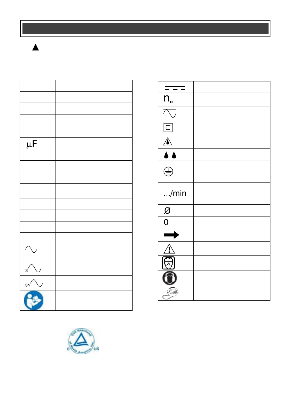
SYMBOLS
WARNING:
Some of the following symbols may appear on the siding shear. Study
these symbols and learn their meaning. Proper interpretation of these symbols will
allow for more efficient and safer operation of this tool.
!
This symbol designates that this tool is
li
sted with U.S. requirements by
TÜV R
heinland.
Co
nforms to UL Std. 60745-1 and
6074
5-2-8.
JD2035U
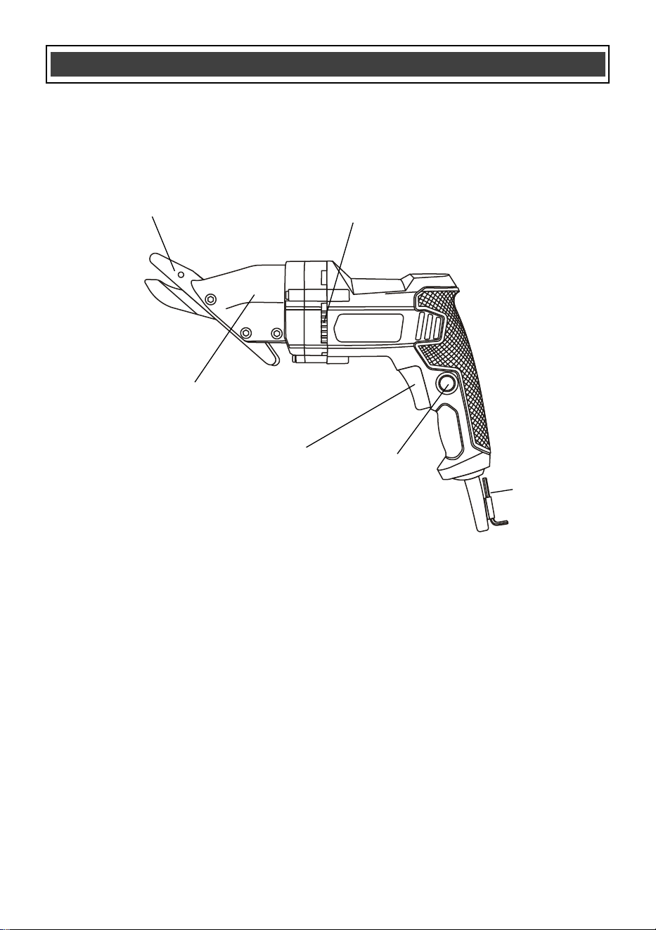
10
KNOW YOUR CEMENT FIBER SIDING SHEAR
Lock-on
button
Variable speed
trigger switch
Cutting blade
set
360° Swivel head
Air vents
4 mm
Hex key
11
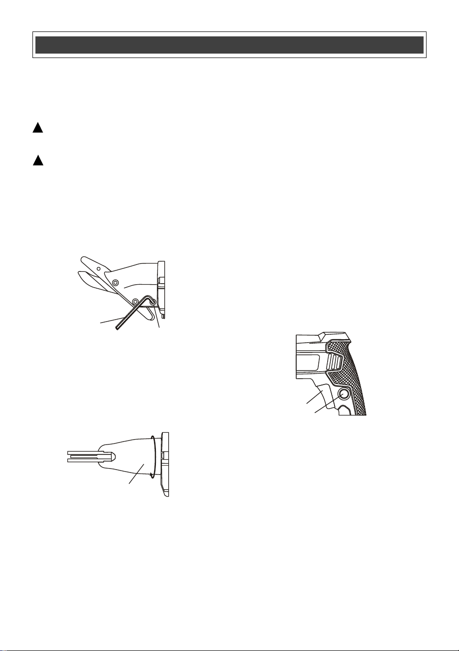
ADJUSTING THE 360° SWIVEL HEAD
The cutting head can be rotated through 360° to
allow the handle to be positioned so it will not
interfere with the cutting area.
WARNING:
Remove the plug from the
power source before adjusting the swivel head.
WARNING: Wear heavy duty protective
gloves when adjusting the cutting head. The
blades are sharp and can pinch your fingers,
causing serious injury.
1. Loosen the swivel head screw (1) using the
4 mm hex key (2) (Fig. 1).
NOTE: Rotate t
he screw two turns counter
clockwise.
2. Grasp the body of the tool with one hand
and the body of the swivel head (3) with
the other hand and rotate the swivel head
to the desired position.
3. Re-tighten the swivel head screw.
TRIGGER SWITCH & LOCK-ON BUTTON
The siding shear has a variable speed trigger
switch (1) (Fig. 3).
1. To start the tool at the lowest speed, gently
squeeze the trigger switch. To increase the
speed, squeeze the trigger switch harder.
2. To
stop the tool. Release the trigger switch.
When operating the tool for extended periods of
time at its fastest speed, the lock-on button can
be used to lock the trigger switch ON.
3. To lock the trigger ON, squeeze the trigger
until the tool is running at its fastest speed.
While squeezing the trigger, press the
lock-on button (2) into the handle. While
holding the lock-on button into the handle,
release the trigger. The tool will continue to
run at its fastest speed.
4. To turn the tool OFF, squeeze and then
releas
e the trigger.
ASSEMBLY AND OPERATING
!
!
Fig. 1
1
2
Fig. 2
3
Fig. 3
1
2
12
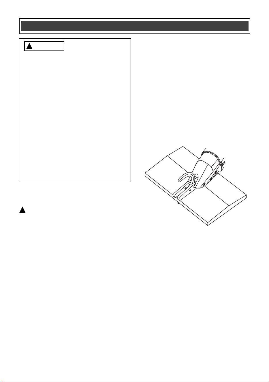
CUTTING
WARNING: Before beginning to cut, make
sure the work area is clear of any foreign
objects and the cutting line is clearly marked on
the workpiece. Secure small workpieces in a
vise or to a stable platform.
Before cutting the "good" workpiece, make
practice cuts on a "scrap" workpiece until you
are comfortable with operating the tool and with
your ability to follow cutting lines.
1. Place the cutting jaws of the tool a
t the
edge of the workpiece.
NOTE: Make sure the cutting jaws are
aligned with the cutting mark, allowing for
adequate room for the material being cut
away. The cut will be at least 1/16" wide.
2. Squeeze the switch trigger and gradually
move the cutting blades into the workpiece
(Fig. 4).
NOTE: The scrap piece that is being
removed will normally curl out of the way.
3. When cutting a large workpiece or cutting
curves, you may wish to rotate the cutting
head to reduce the interference with
the
tool handle. Refer to "ADJUSTING THE
360° SWIVEL HEAD" (Fig. 1).
ASSEMBLY AND OPERATING
!
Fig. 4
For safety reasons, the operator must
read the sections of this Owner’s Manual
entitled "GENERAL SAFETY
WARNINGS", "POWER TOOL SAFETY",
"SPECIFIC SAFETY RULES",
"EXTENSION CORD SAFETY" and
"SYMBOLS" before using this siding
shear.
Verify the following every time the siding
shear is used:
1. Dust mask is being worn.
2. Safety shield, hearing protection,
heavy gloves and protective clothing
are being worn.
3. The blades are sharp and in good
condition.
Failure to observe these saf
ety rules will
significantly increase the risk of injury.
WARNING
!
13
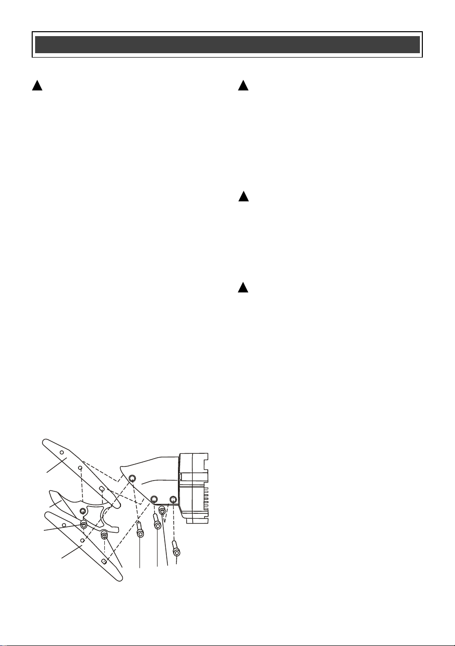
REPLACING THE CUTTING BLADES
WARNING: Remove the plug from the
power source before removing or installing
cutting blades. Use caution when handling the
cutting blades, as they are sharp and can cause
serious injury.
After considerable use, the cutting blades will
become worn and will have to be replaced. The
following instructions detail how to remove and
replace the blades.
Removing old cutting blades
1. Remove all three blade screws (1) (Fig. 5).
NOTE: Turn the
screws counter clockwise
using the 4 mm hex key.
2. Remove all three blades (2, 3 & 4).
NOTE: Do not lose the two short spacers
(5 & 6) and the lone spacer (7).
Installing new cutting blade set 236-0994
(Available at your nearest Menards store)
3. Install the new in the reverse order of
"removing old blades" above.
NOTES:
a. The left blade (2) has two slotted holes.
The right blade (4) has one slotted hole
and one round hole.
b. Place the long spacer (7) to the rear of the
c
utting head
c. Make sure the blade screw nuts are
properly nested in the swivel housing
before tightening the blade screws. Do not
over tighten the screws.
GENERAL
WARNING: When servicing, use only
identical replacement parts. The use of any
other part may create a hazard or cause
product damage.
DO NOT use solvents when cleaning plastic
parts. Plastics are susceptible to damage from
various types of commercial solvents and may
be damaged by their use. Use a clean cloth to
remove
dirt, dust, oil, grease etc.
WARNING: Do not allow brake fluids,
gasoline, petroleum-based products,
penetrating oils, etc. to come into contact
with plastic parts. They contain chemicals
that can damage, weaken or destroy plastic.
DO NOT abuse power tools. Abusive practices
can damage the tool and the workpiece.
WARNING: DO NOT attempt to modify
tools or create accessories. Any such
alteration or modification is misuse and
could result in a hazardous condition
leadi
ng to possible serious injury. It will also
void the warranty.
LUBRICATION
All of the bearings in this tool are lubricated with
a sufficient amount of high-grade lubricant for
the life of the unit under normal conditions.
Therefore, no further lubrication is required.
MAINTENENCE
!
!
!
!
Fig. 5
1
2
7
1
1
6
5
3
4
14
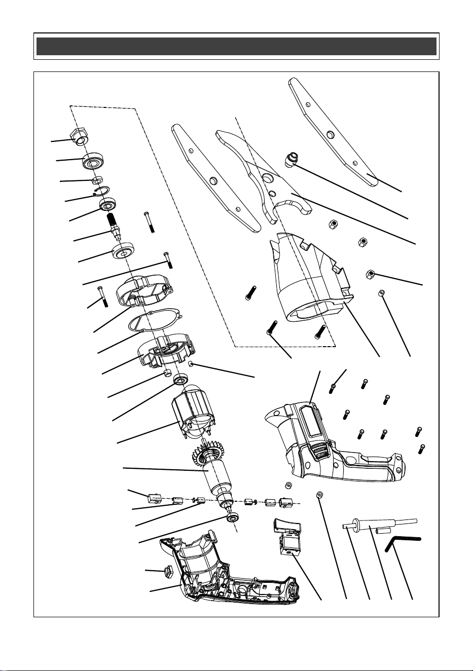
EXPLODED VIEW
5
4
3
2
1
6
7
8
9
10
11
12
13
14
15
16
17
18
19
20
21
22
23
24
25
26
27
28
29
6
30
31
32
33
34
35
36

15
WARNING: When servicing, use only original equipment replacement parts. The use of any other
parts may create a safety hazard or cause damage to the siding shear.
Any attempt to repair or replace electrical parts on this siding shear may create a safety hazard unless
repairs are performed by a qualified technician. For more information, call the Toll-free Helpline, at
1-866-349-8665.
Always order by PART NUMBER, not by key number.
Key #
Part #
Part Name
Quantity
1
6140020011
Hex key
1
2
3140010053
Cord guard
1
3
1190030069
UL plug and cord
1
4
3140060014
Buffer cap
2
5
1061020006
Switch
1
6
3011290001
Housing
2
7
3110010259
Decorative board
1
8
4010010035
Bearing
1
9
1230010103
Carbon brush
2
10
2030070004
Copper brush holder
2
11
3150060002
Brush box
2
12
1010300004
Rotator
1
13
1020300004
Stator
1
14
4010010048
Bearing
1
15
4010020036
Needle bearing
1
16
2020020037
Gear box back cover
1
17
3190060009
Gasket
1
18
2020020036
Gear box front cover
1
19
4030010128
Screw
2
20
4030010229
Screw
1
21
2040080038
Output gear
1
22
2040290077
Output shaft
1
23
4010010054
Bearing
1
24
4100010002
Circlip for hole
1
25
2030020271
Washer
1
26
4010010126
Bearing
1
27
2040290111
Eccentric wheel
1
28
3140060031
Buffer post
1
29
4020080076
Screw
3
30
4030010106
Screw
8
31
2020050099
Aluminum shell
1
32
2040310064
Bushing
1
33
4060090018
Nut
3
34
2040250034
Blade
1
35
2040310063
Bushing
1
36
2040250033
Blade
2
PARTS LIST
!

16
PERFORMAX
®
FIBER CEMENT SIDING SHEAR WARRANTY
2-YEAR LIMITED WARRANTY:
This PERFORMAX
®
brand power tool carries a 2-Year Limited Warranty to the
original purchaser. If, during normal use, this PERFORMAX
®
power tool breaks
or fails due to a defect in material or workmanship within two (2) years from the
date of original purchase, simply bring this tool with the original sales receipt
back to your nearest MENARDS® retail store. At its discretion, PERFORMAX
®
agrees to have the tool or any defective part(s) repaired or replaced with the
same or similar PERFORMAX
®
product or part free of charge, within the stated
warranty period, when returned by the original purchas
er with original sales
receipt. Not withstanding the foregoing, this limited warranty does not cover any
damage that has resulted from abuse or misuse of the Merchandise. This
warranty: (1) excludes expendable parts including but not limited to blades,
brushes, belts, bits, light bulbs, and/or batteries; (2) shall be void if this tool is
used for commercial and/or rental purposes; and (3) does not cover any losses,
injuries to persons/property or costs. This warranty does give you specific legal
rights and you may have other rights, which vary from state to state. Be careful,
tools are dangerous if improperly used or maintained. Seller’s employees
are
not qualified to advise you on the use of this Merchandise. Any oral
representation(s) made will not be binding on seller or its employees. The rights
under this limited warranty are to the original purchaser of the Merchandise and
may not be transferred to any subsequent owner. This limited warranty is in lieu
of all warranties, expressed or implied including warranties or merchantability
and fitness for a particular purpose. Seller shall not be liable for any special,
incidental, or consequential damages. The sole exclusive remedy against the
seller will be for the replacement of any defects as provided herein, as long as
the seller is willing or able to replace this product or is wil
ling to refund the
purchase price as provided above. For insurance purposes, seller is not allowed
to demonstrate any of these power tools for you.
For questions / comments, technical assistance or repair parts –
Please Call Toll Free at: 1-866-349-8665 (9-5pm Monday-Friday EST)
Or email us at: customerservice@powertoolsplus.ca
SAVE YOUR RECEIPTS. THIS WARRANTY IS VOID WITHOUT THEM.
Rev 1.5 15/07/2025
Distributed by: Menard, Inc., Eau Claire, WI 54703