
1
Technical Support and E-Warranty Certificate
www.vevor.com/support
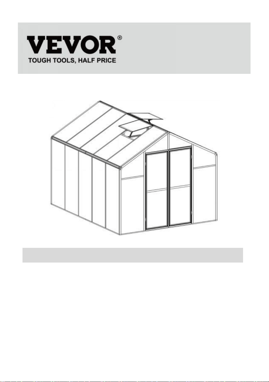
POLYCARBONATE GREENHOUSE
USER MANUAL
We continue to be committed to provide you tools with competitive price.
"Save Half", "Half Price" or any other similar expressions used by us only
represents an estimate of savings you might benefit from buying certain tools
with us compared to the major top brands and does not necessarily mean to cover
all categories of tools offered by us. You are kindly reminded to verify carefully
when you are placing an order with us if you are actually Saving
Half in comparison with the top major brands.

1
1
Model
:
AM035
NEED HELP? CONTACT US!
Have product questions? Need technical support? Please feel free to contact
us:
Technical Support and E-Warranty Certificate
www.vevor.com/support
This is the original instruction, please read all manual instructions carefully before
operating. VEVOR reserves a clear interpretation of our user manual. The
appearance of the product shall be subject to the product you received. Please
forgive us that we won't inform you again if there are any technology or software
updates on our product.
POLYCARBONATE
GREENHOUSE

2
INSTRUCTIONS
Thank you very much for choosing this product. Please read all the instructions before using
it.The information will help you achieve the best possible results.
PLEASE NOTE! Drawings in this manual are for illustration purposes only and in some
details may differ from the actual product.
ATTENTION! Read all safety warnings and all instructions. Failure to follow the warnings
and instructions may result in serious injury or even death. The device or product used in
the warning instructions is referred to Polycarbonate greenhouse.
This product is not a toy or a toy chest. Do not allow children to play with this item. Please
place in a position that children cannot climb to avoid injury from falling from a height.
USAGE SAFETY
1. Two people are required to assemble this product.
2. Some components have sharp metal edges. Please be careful when handling metal
components. Please wear gloves, shoes and safety goggles during assembly.
3. Select an area for assembly that is clean and free of any debris that might cause persons
working on the assembly to trip.
4. Do not climb or stand on the roof. Heavy articles should not be leaned against the
greenhouse.
5. Preview the assembly instructions in your operator’s manual before proceeding further.
6. After completing assembly, thoroughly inspect the machine to be sure that all nuts, bolts,
hydraulic fittings or any other fastener assemblies have been thoroughly tightened.
67. This product is not a play facility or tent and should not be used for purposes other than
polycarbonate greenhouses.
8. The polycarbonate greenhouse must be checked to ensure that it is in proper working
order and is operating safely prior to use. Otherwise , the appliance must not be used.
9. We recommend placing the bottom frame in a pre-dug trench after securing the board
with expansion screws (include) to the ground for greater stability and temperature chamber
wind resistance.
10. Recommend to apply glass glue to the connection between PC board and frame for
better water protection.
11. When the weather is bad, we recommend that the precious items in the greenhouse be
removed to avoid unnecessary property loss and do not use greenhouse during that time.
12. Keep the roof clear of snow & leaves. Allowing snow to build up on the roof may damage

3
the product.
Before using the product - if you have any questions regarding the proper assembly or
operation, contact your dealer or representative.
13. When your product needs cleaning, use a mild detergent solution and rinse with cold
clean water. Do not use acetone, abrasive cleaners or strong detergents to clean the
panels.
SAVE THESE INSTRUCTIONS
TECHNICAL PARAMETERS
Model
AM035
Color
Black aluminum
Material
Aluminum, Polycarbonate sheet
Product size
236*289*206cm
4
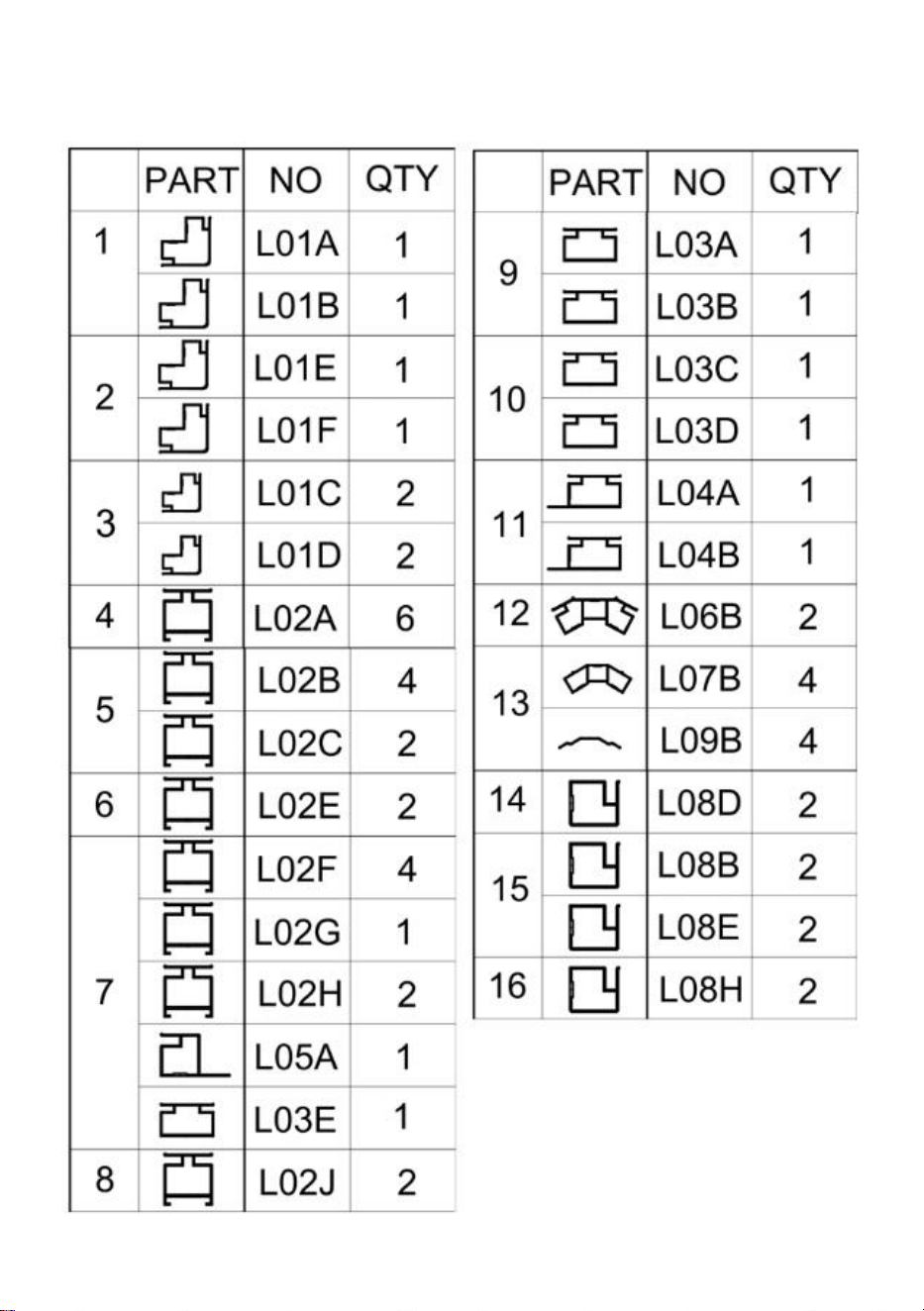
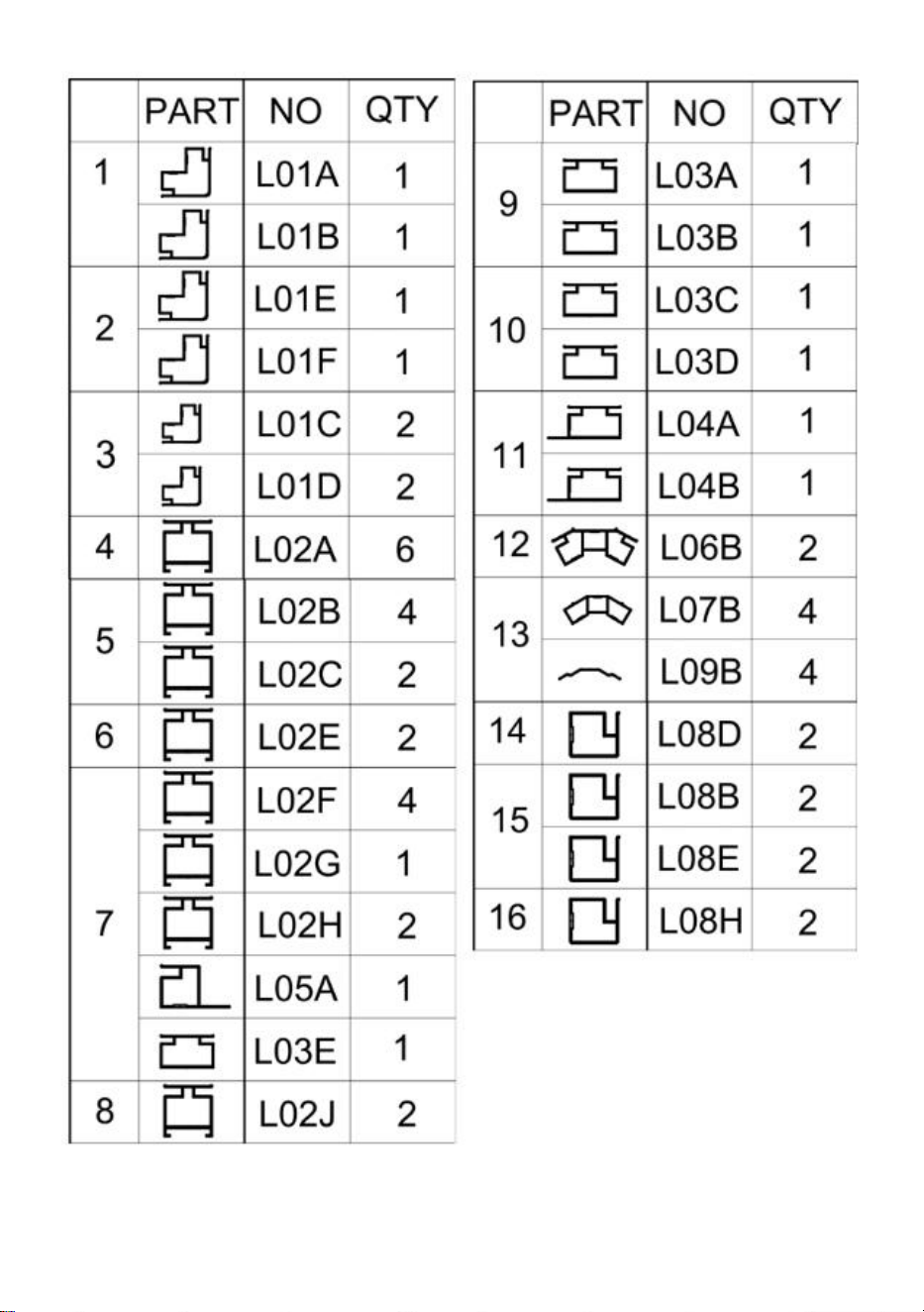
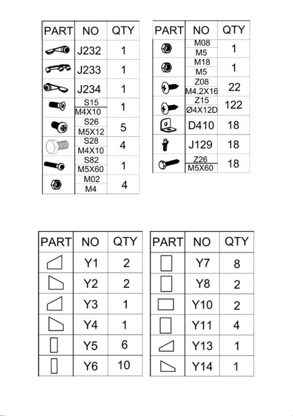
Part List

5

6
PC Board List
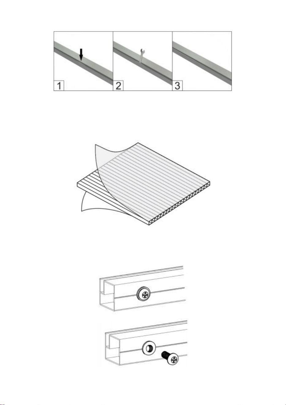
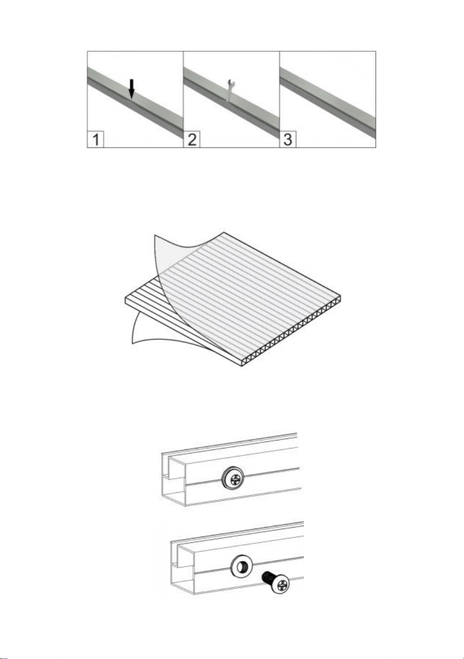
If the aluminum part is curved as in below pic, pls use the wrench to restore it.
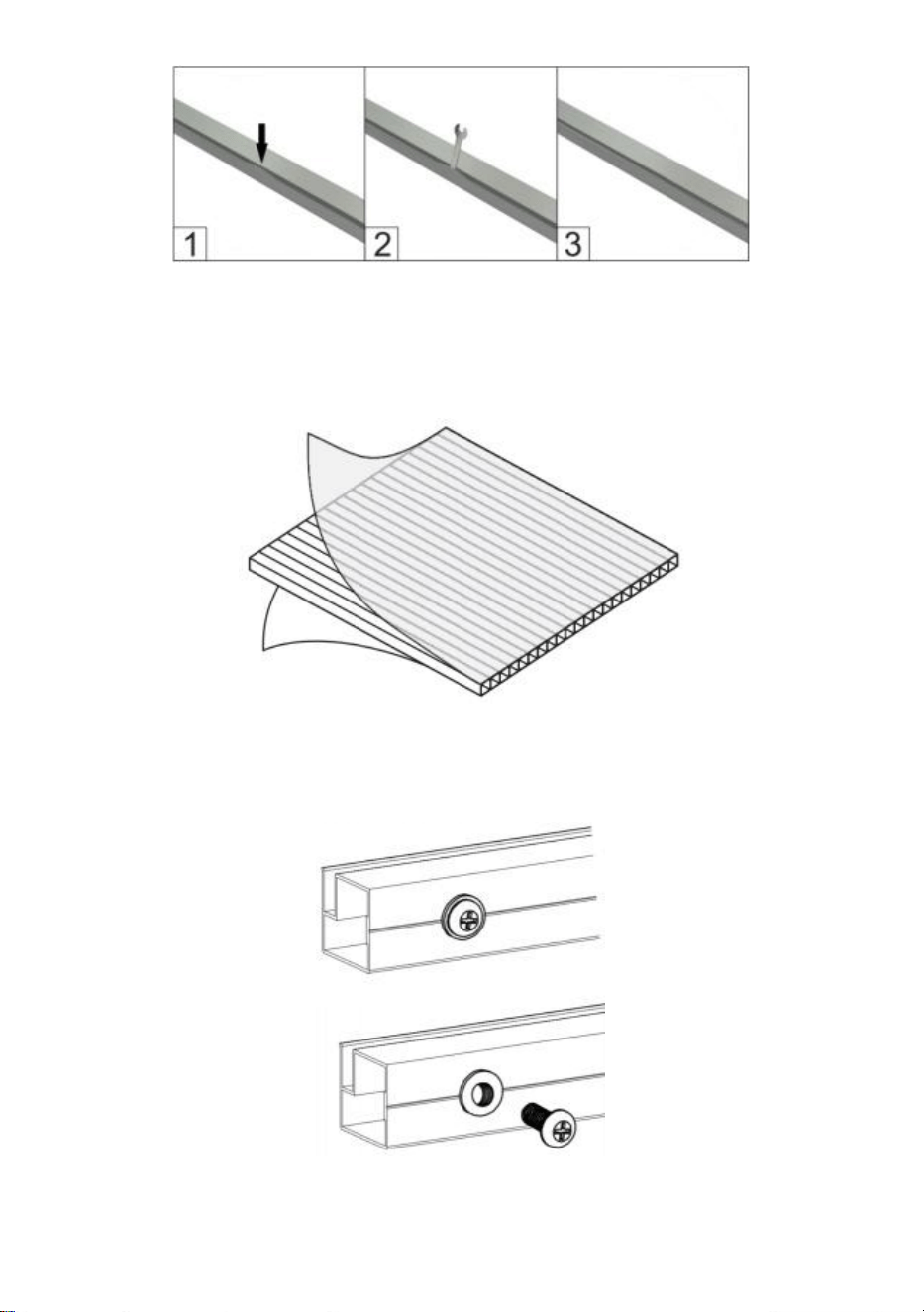
7
Remove approximately 2 inches of film from all sheet edges before installing and remove all
film immediately after the construction is completed. Please ensure that the side with the
white film faces outwards.
Attention: Most of the parts "S26" are installed on the aluminum, and need to be removed
before installation according to the instructions.
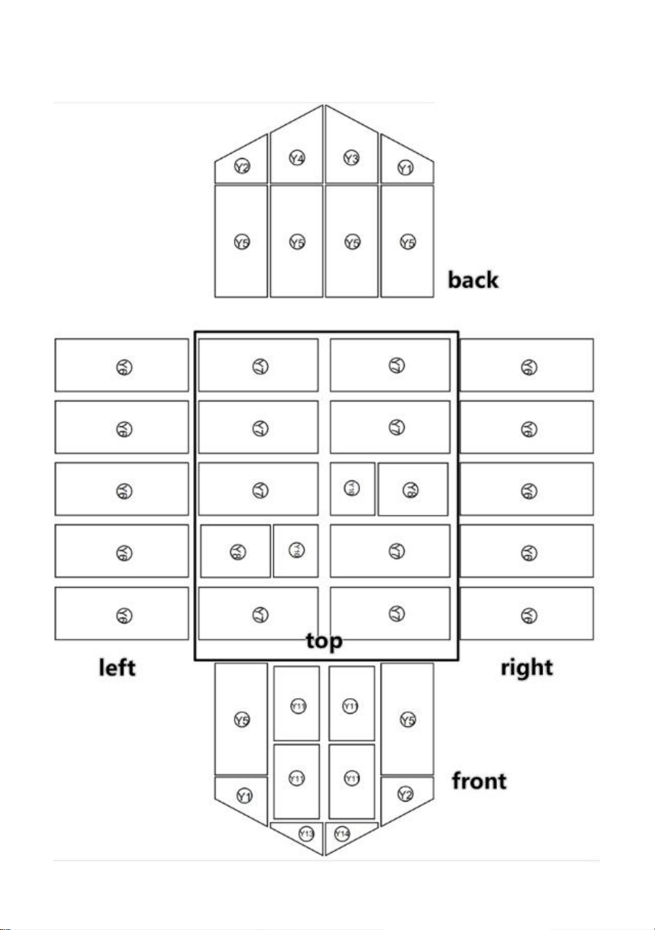
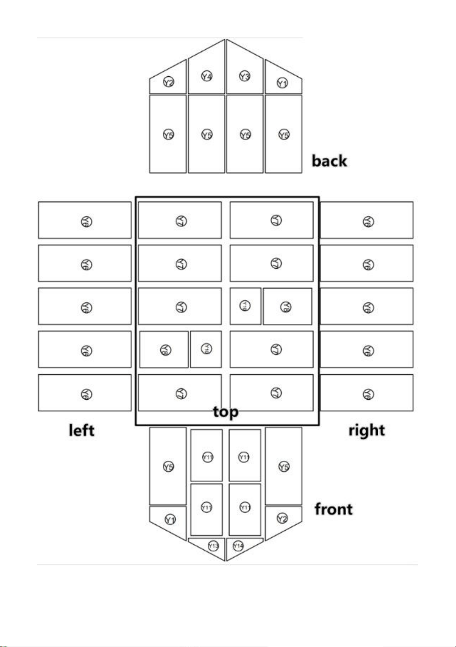
8
PC board distribution
9
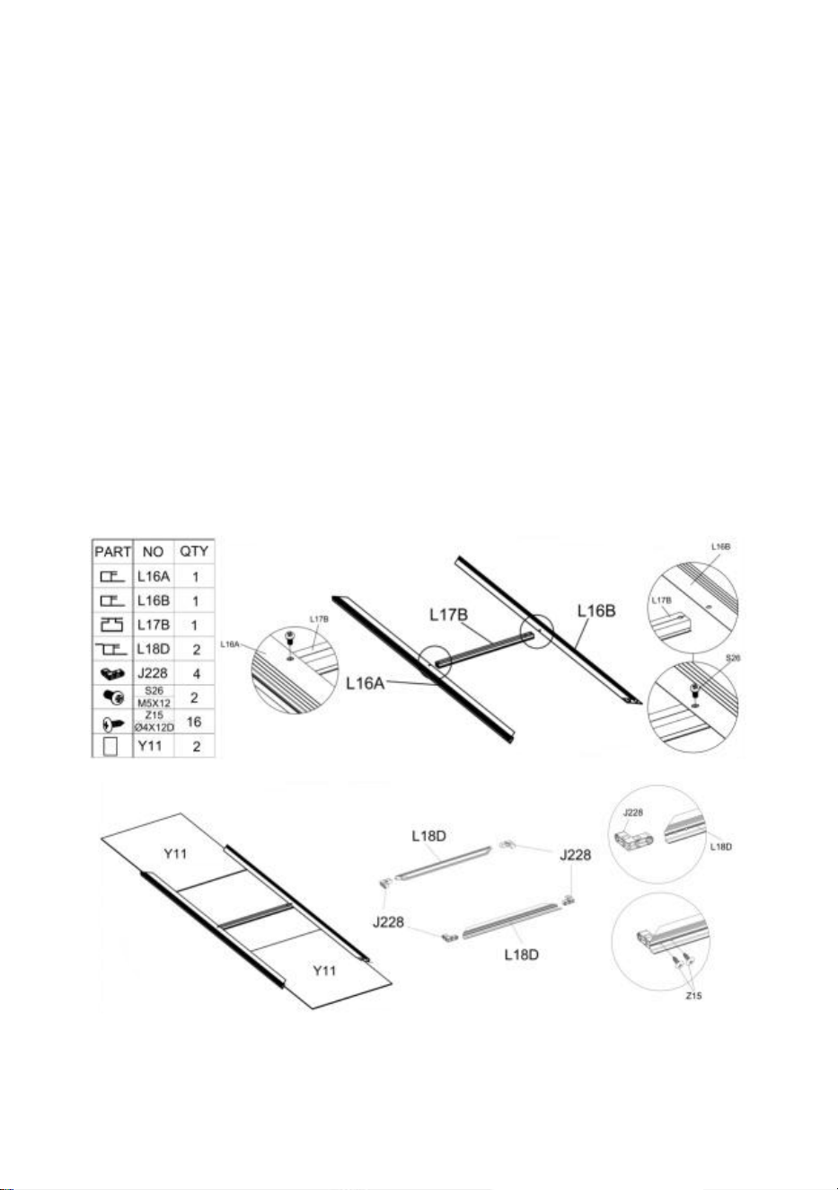
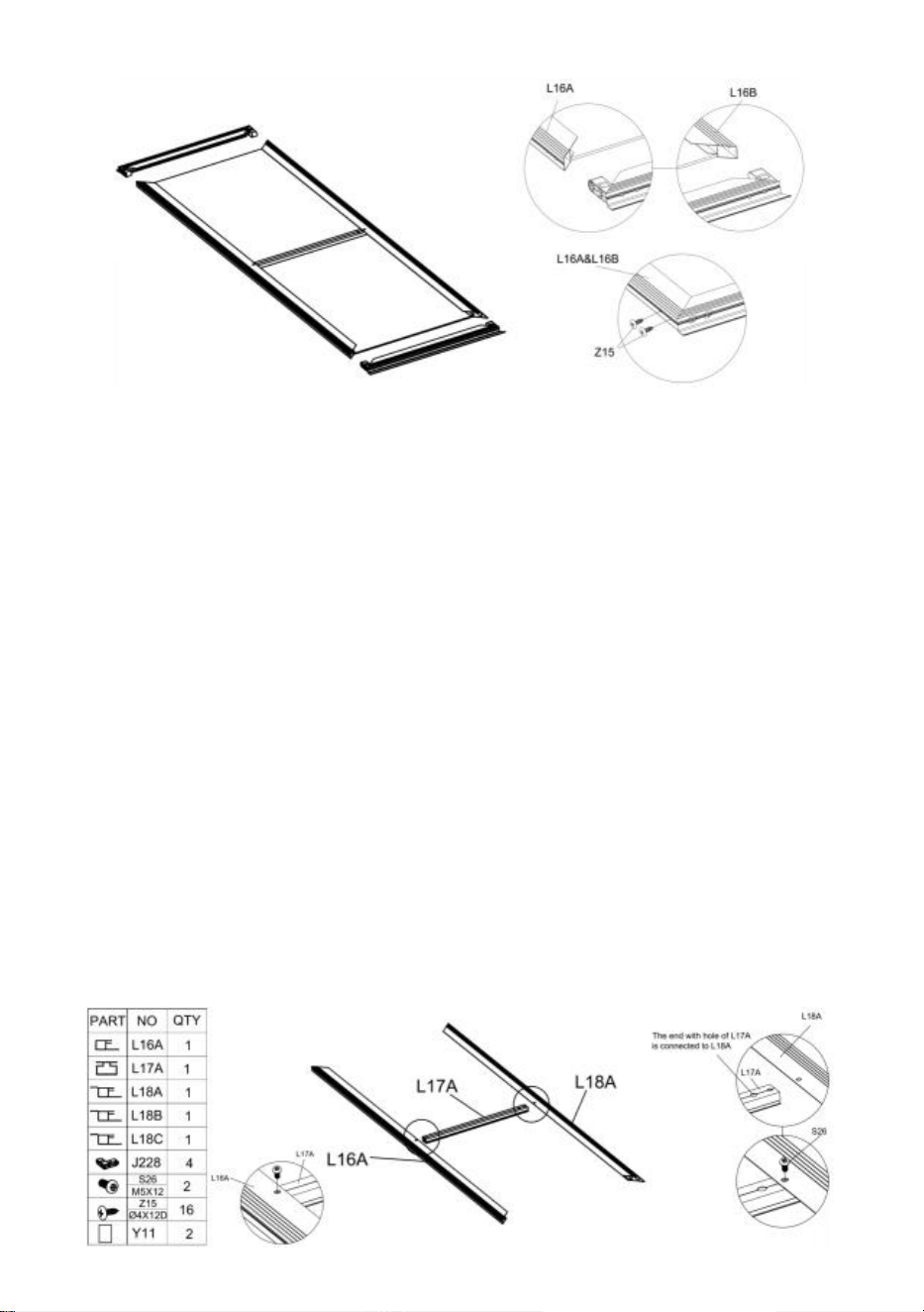
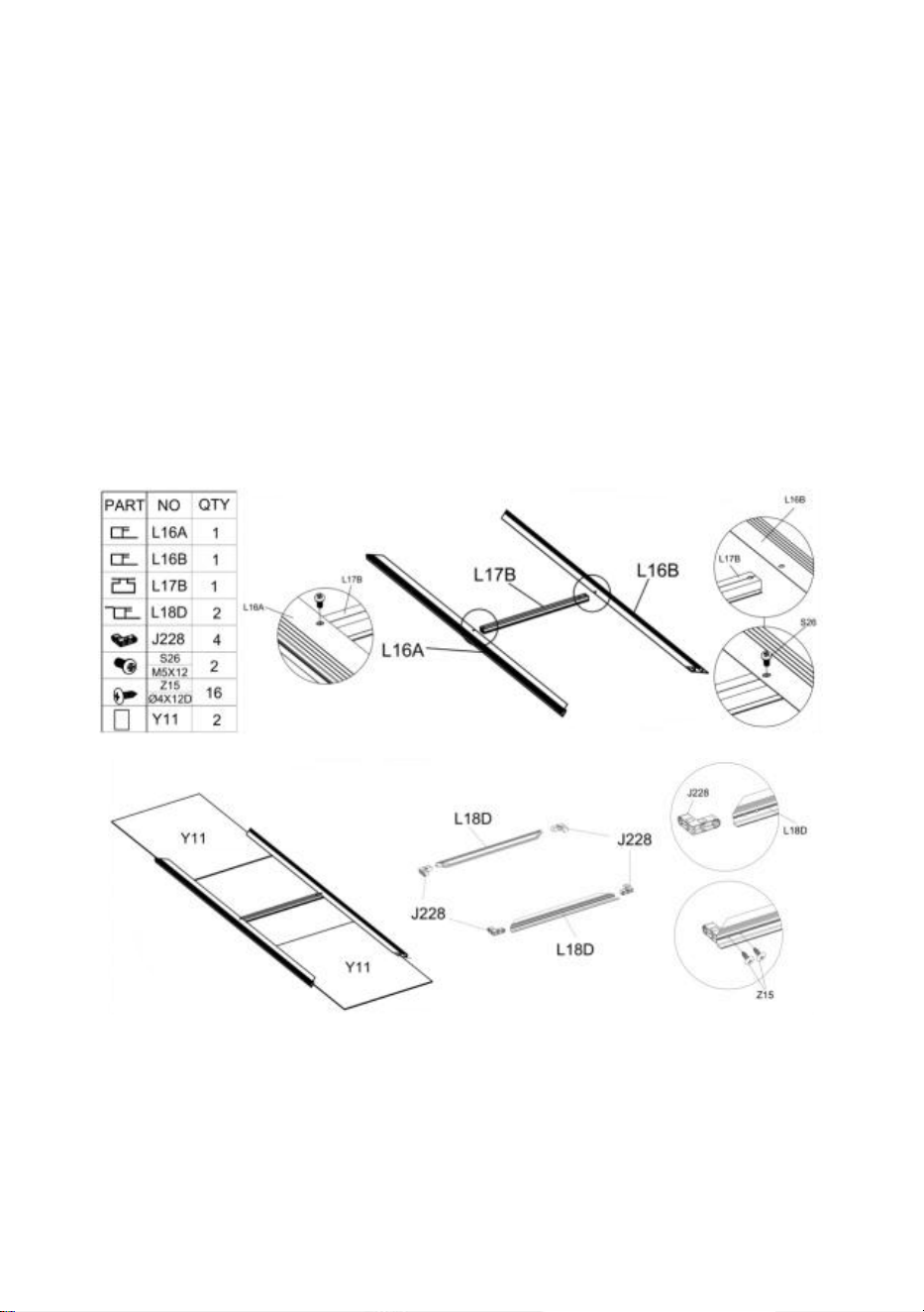
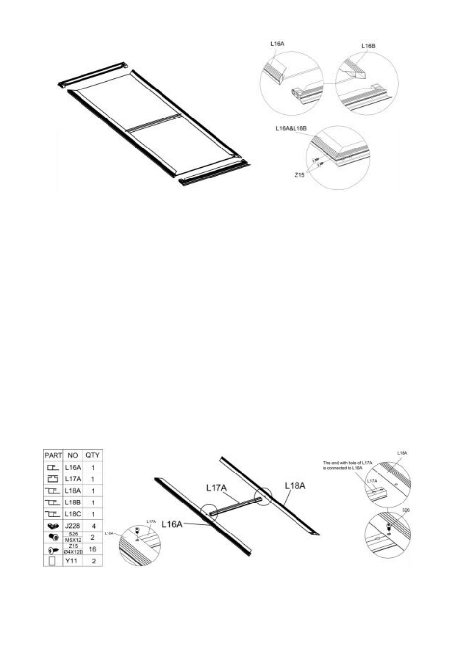
Left Door Assembly
Step 1
:
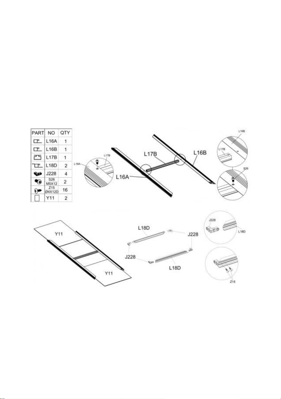
Assemble parts "L17B", "L16A" and "L16B" with part "S26" as shown in the figure. Place
Part "Y11" into the frame.
Step 2
:
Place Part “J228” in the corresponding position of Part “L18D” according to the picture, and
use Part “Z15” to fix it.
Step 3
:
Install the "L18" component assembled in step 2 into the frame according to the figure. After
the component is assembled in place, secure it using Part "Z15".
10
Right Door Assembly
Step 1
:
Assemble parts "L17A", "L16A" and "L16A" with part "S26" as shown in the figure. Place
Part "Y11" into the frame.
Step 2
:
Place Part "J228" in the corresponding position of Part "L18B" & "L18C" according to the
picture, and use Part "Z15" to fix it.
Step 3
:
Install the "L18" component assembled in step 2 into the frame according to the figure. After
the component is assembled in place, secure it using Part "Z15".

11
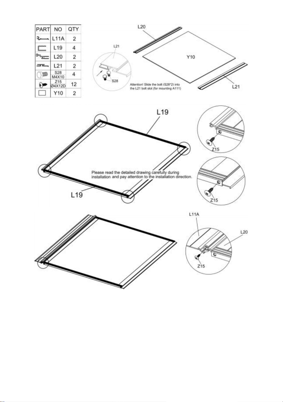
Window Assembly
Step 1
:
Slide Part "S28" into Part "L21" as shown in the figure. Then assemble Part "L20" , "L21"
& "Y10" together.
Step 2
:
Use part "Z15" to assemble Part "L19" with the components completed in the previous step.
Step 3
:
Use part "Z15" to assemble Part "L11A" with the components completed in step 2.
Attention
:
There is 2 Windows in total.

12

13
Greenhouse Assembly
Step 1
:
Please refer to the picture for the location of the parts required for installation in this step.
Corner: Assemble Part "J217" & "L08" using Part "Z15".
Aluminum bar connection: After the two aluminum bars are connected using Part "J222" ,
they are fixed with Part "Z15".
14
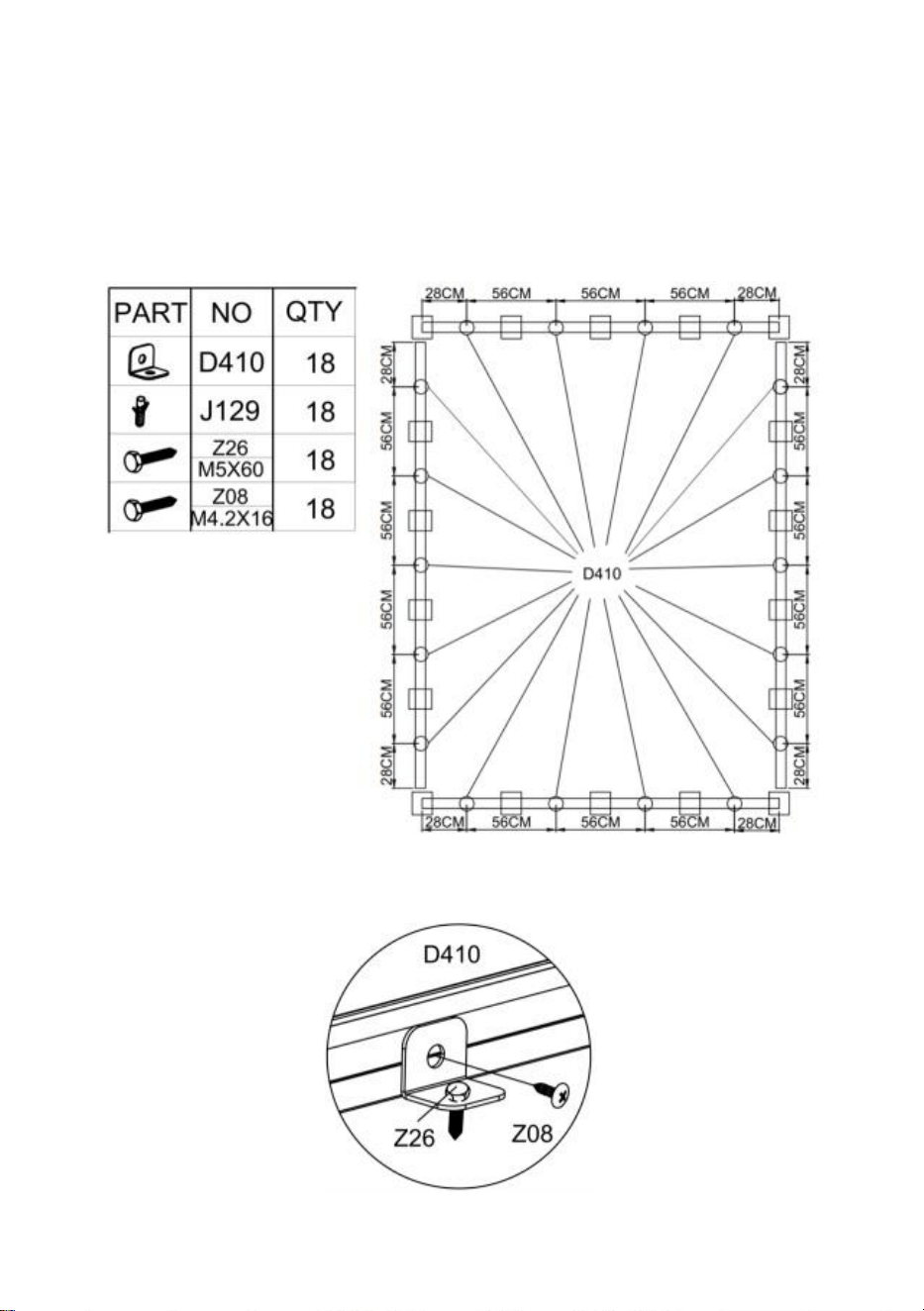
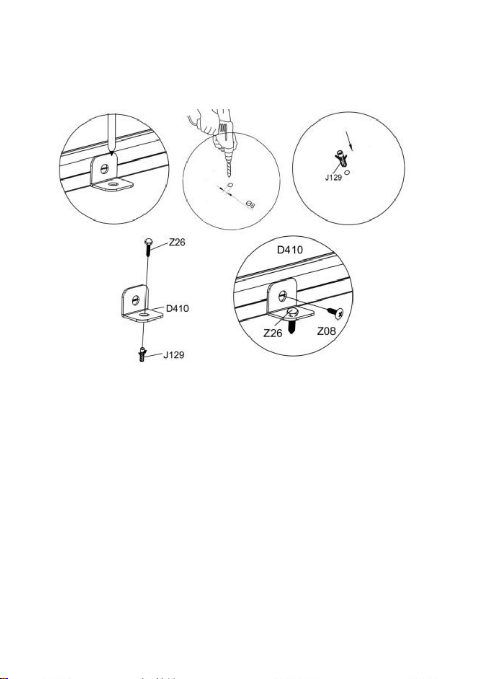
Step 2
:
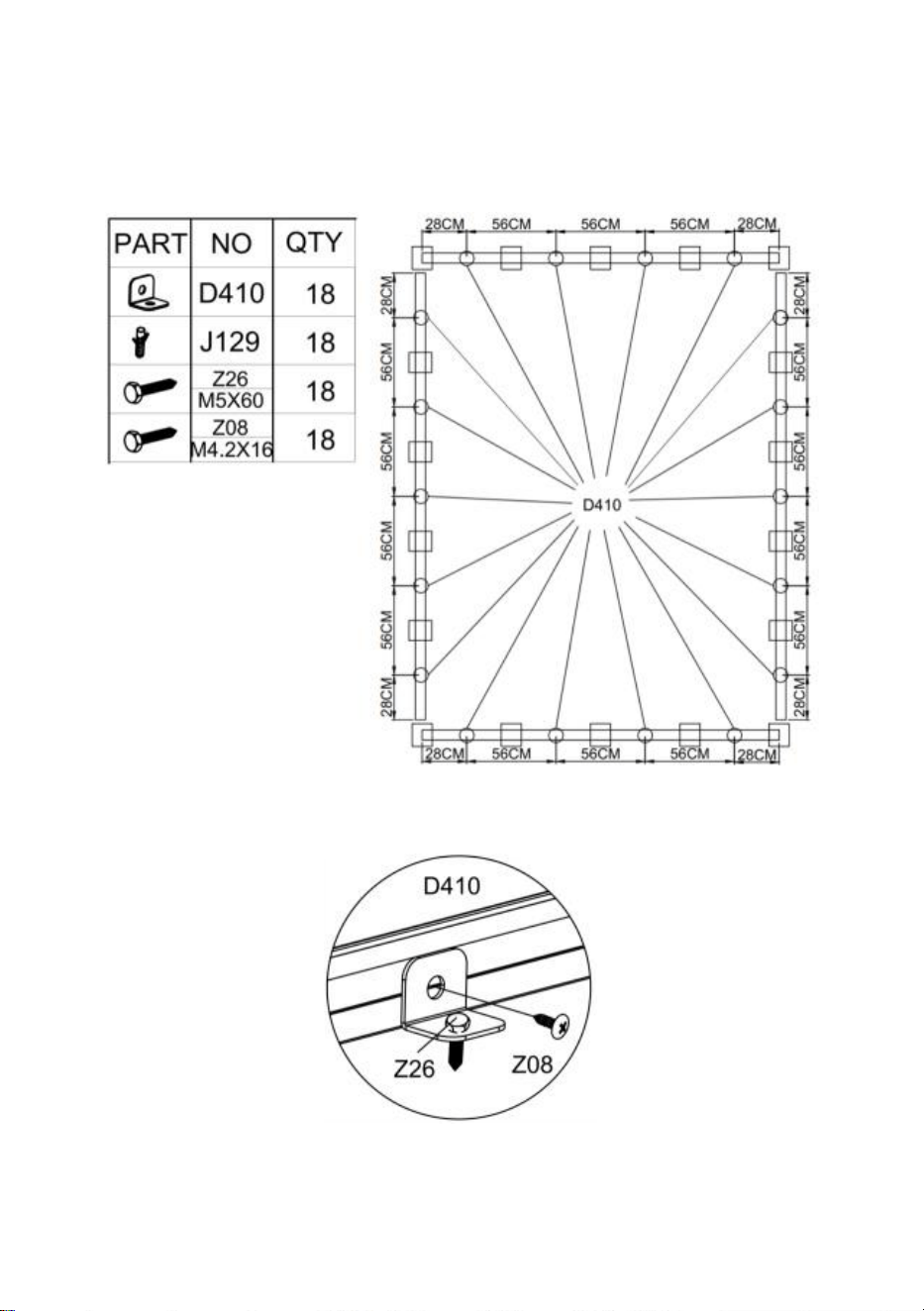
If you plan to attach your greenhouse to solid ground, you can follow this step to make your
greenhouse more secure.
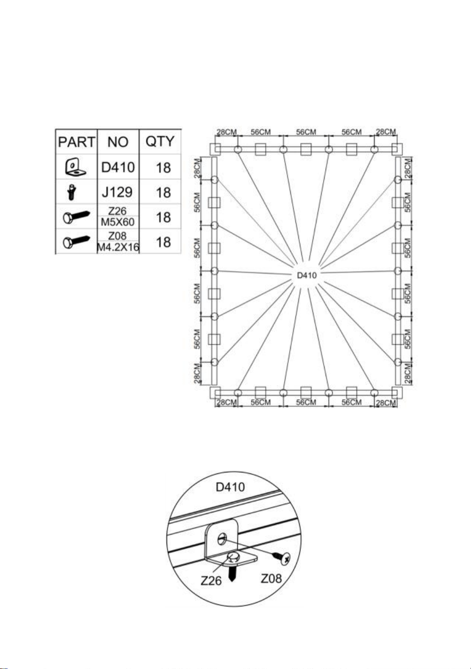
The installation position of connector Part "D410" is shown in the following figure.
If you plan to fix the greenhouse to the wood floor, refer to the figure below to connect the
wood floor to the greenhouse using Part "D410" , "Z08" & "Z26".
15
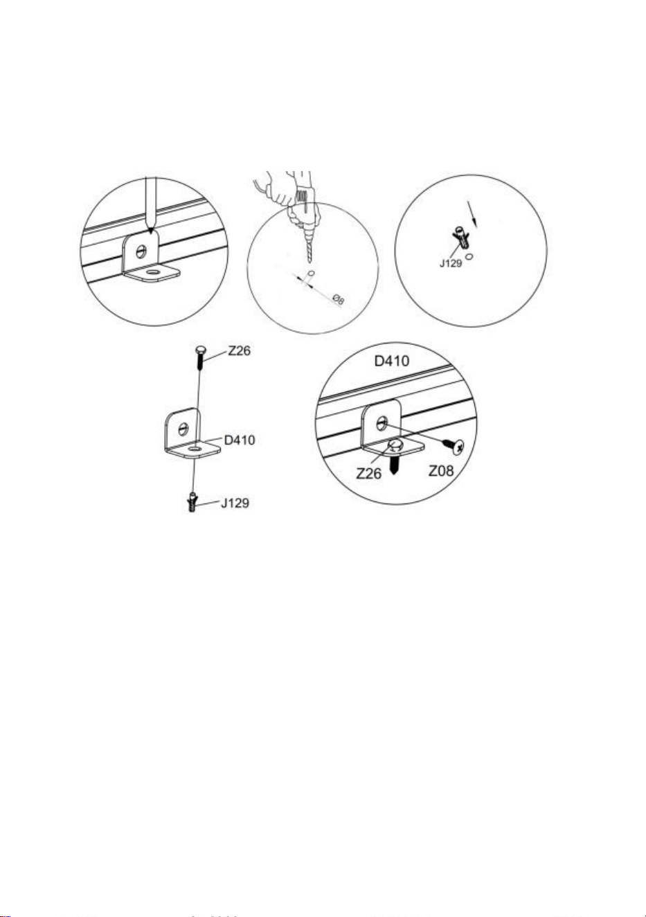
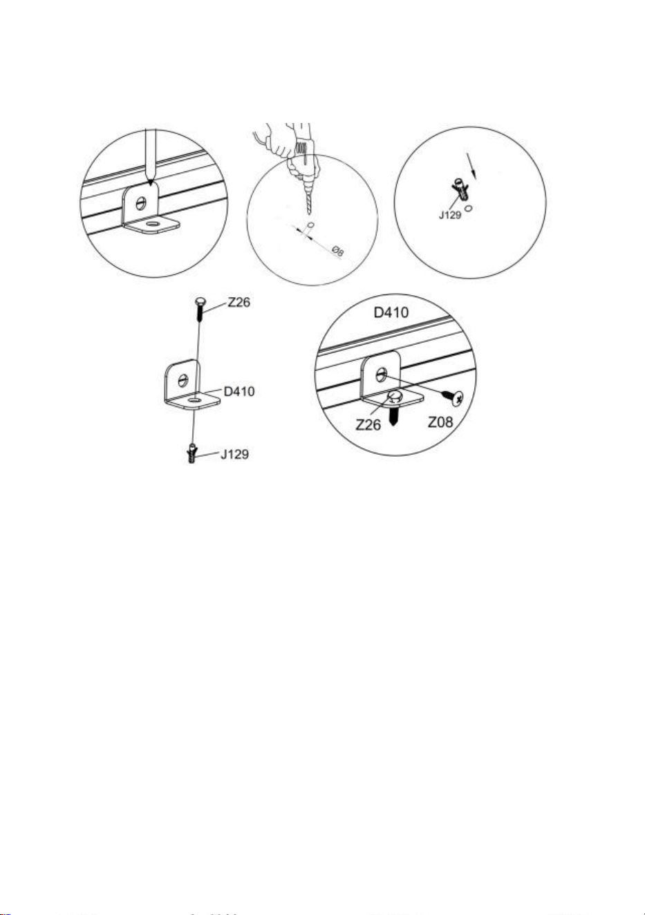
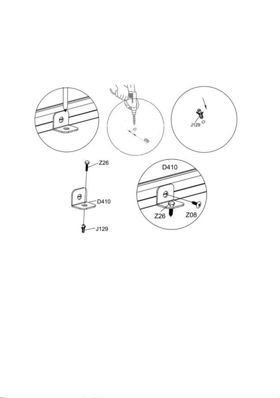
If you plan to install it on a solid floor, such as concrete. Please first determine the location
of the hole to be drilled, use the power tool to drill the 8mm diameter hole, use a hammer or
similar tool to knock Part "J129" into the ground, and finally use Part "D410", "Z26" & "Z08"
to connect the floor to the greenhouse.
16
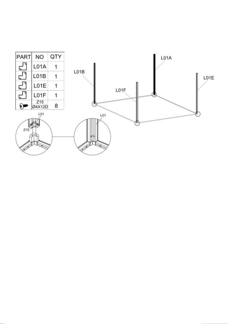
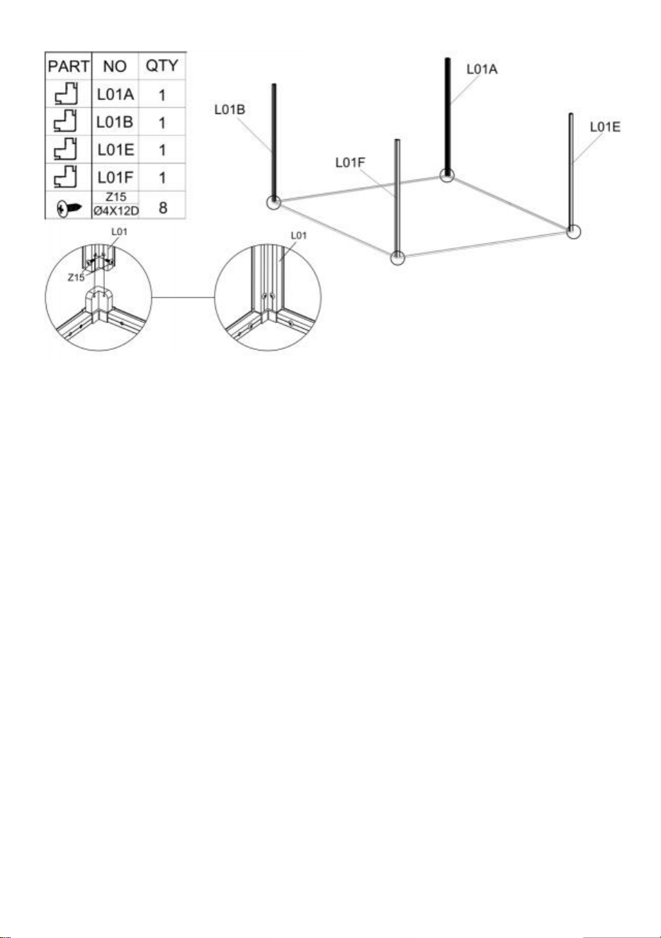
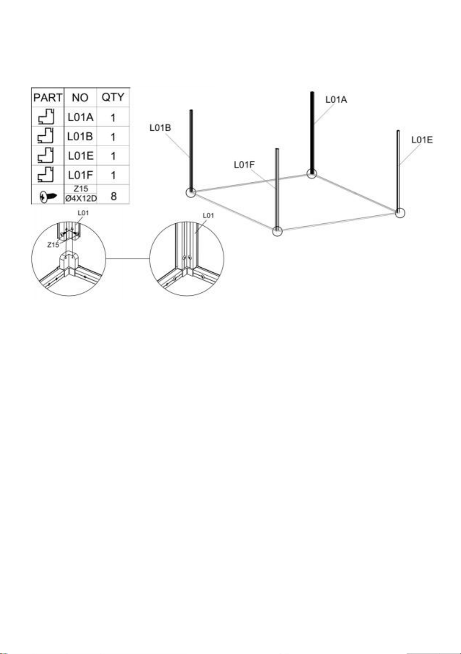
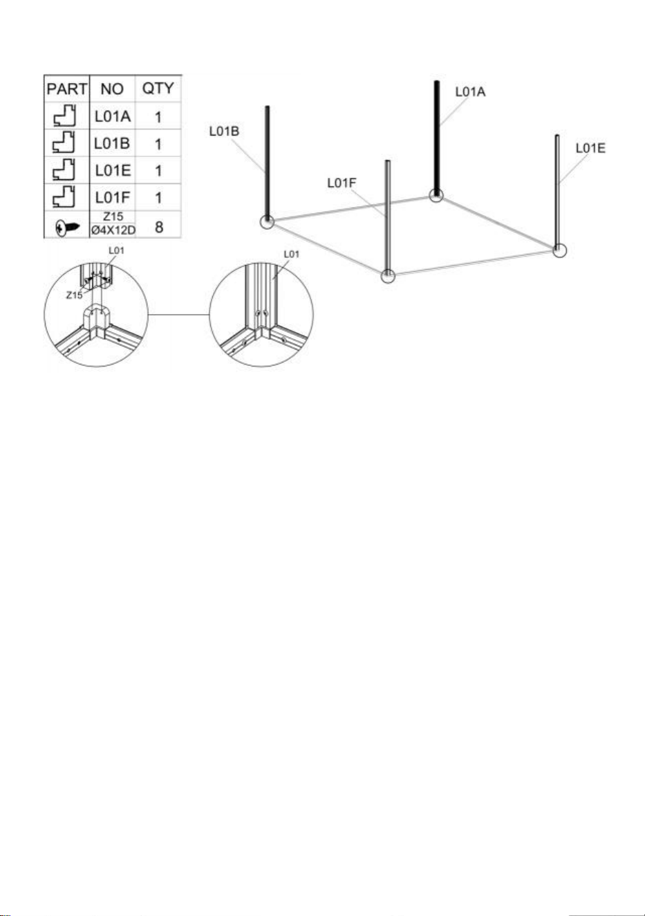
Step 3
:
Assemble Part "L01A" , " L01B ", " L01E " & " L01F " to the components completed in step 1
using Part "Z15".
17
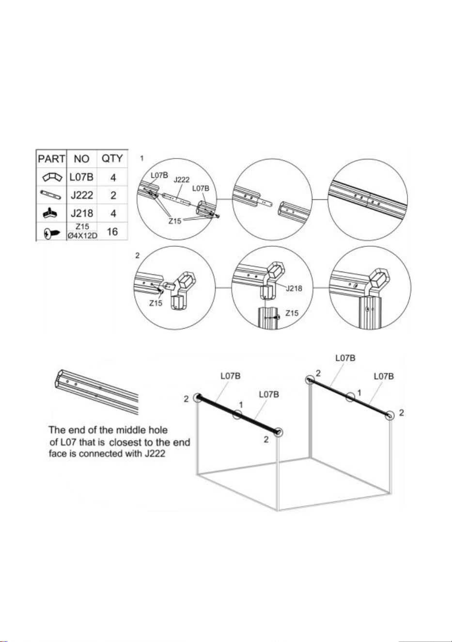
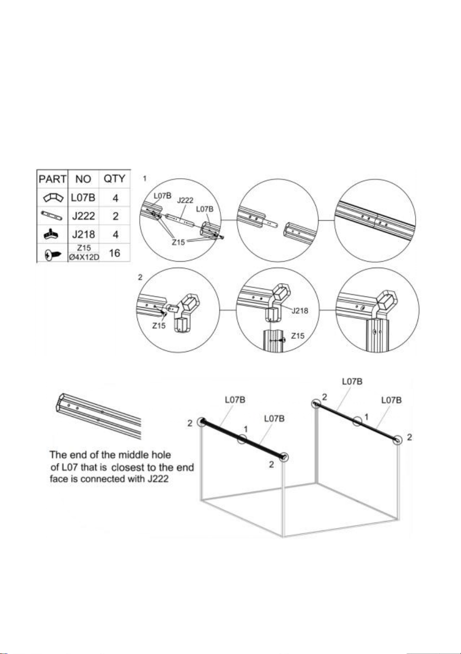
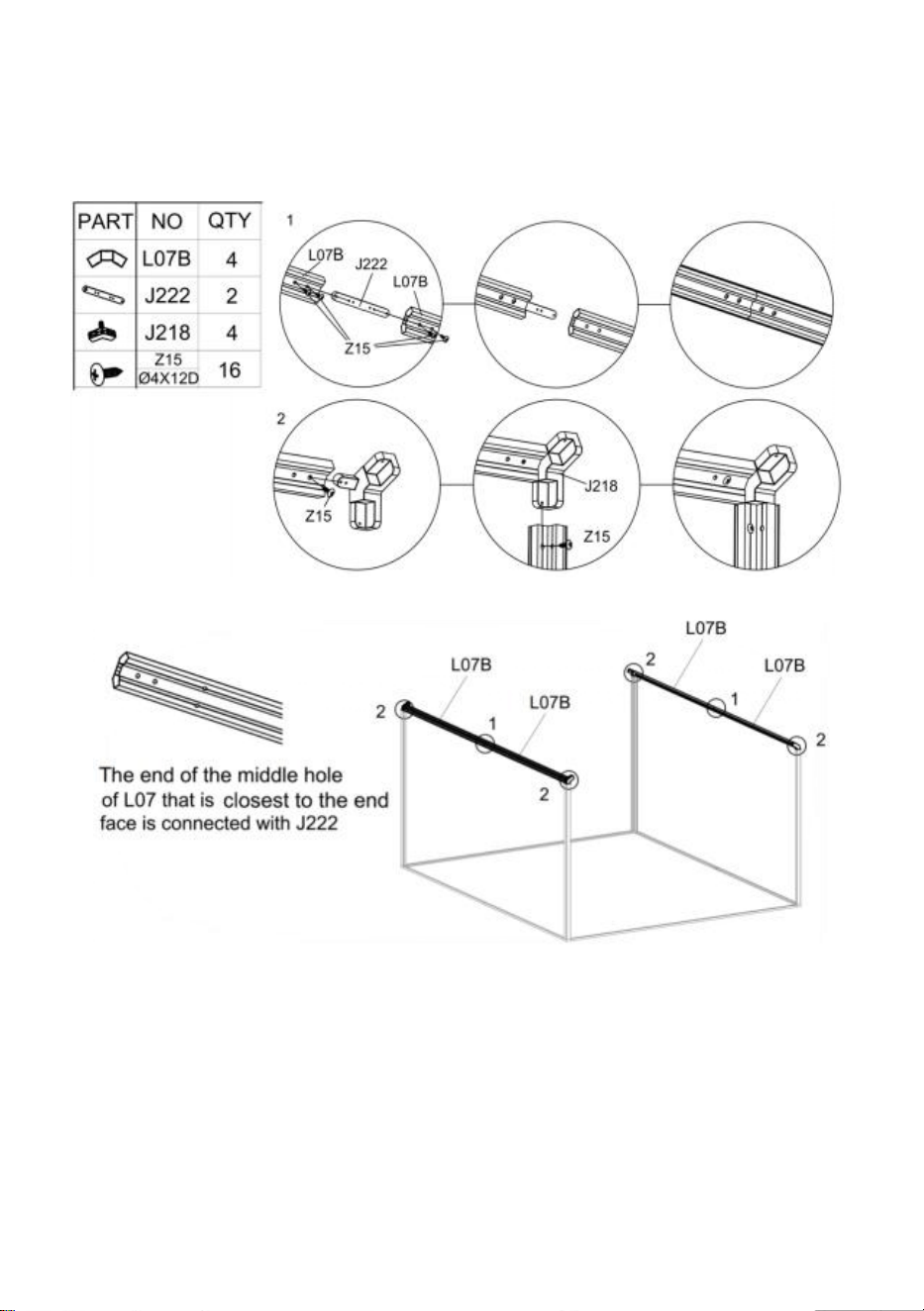
Step 4:
After the two Parts "L07B" are connected using Part "J222" , they are fixed with Part
"Z15".After two Parts "L07B" are connected, install them together with Part "J218"
according to the end of the diagram, and secure them with Part "Z15".
After the installation of the "L07" component, install it on the frame completed in the
previous step according to the figure.
18
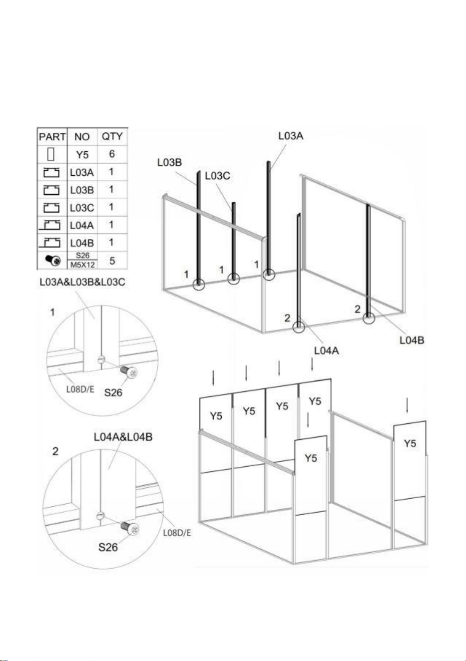
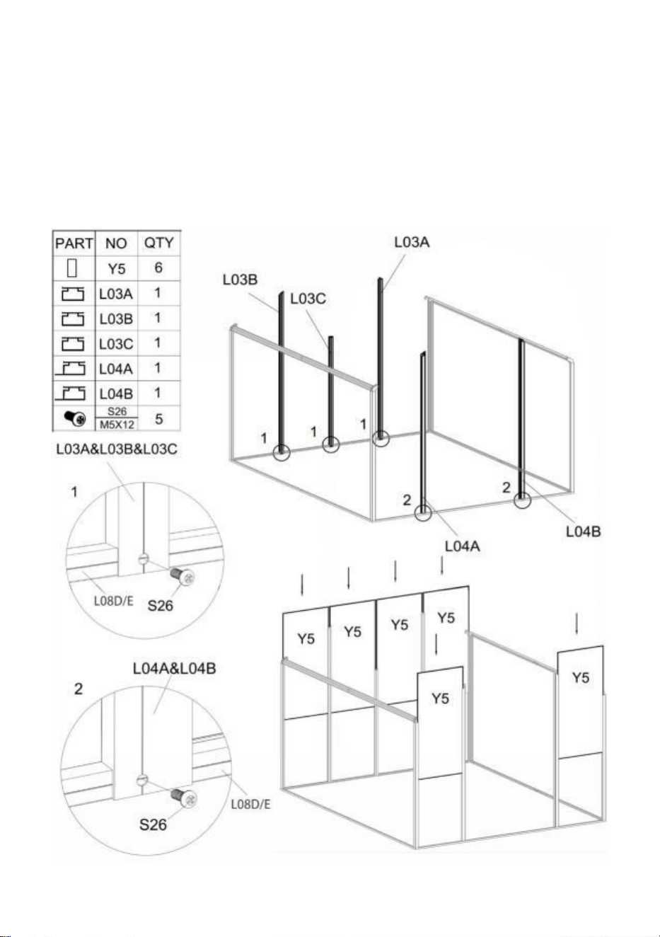
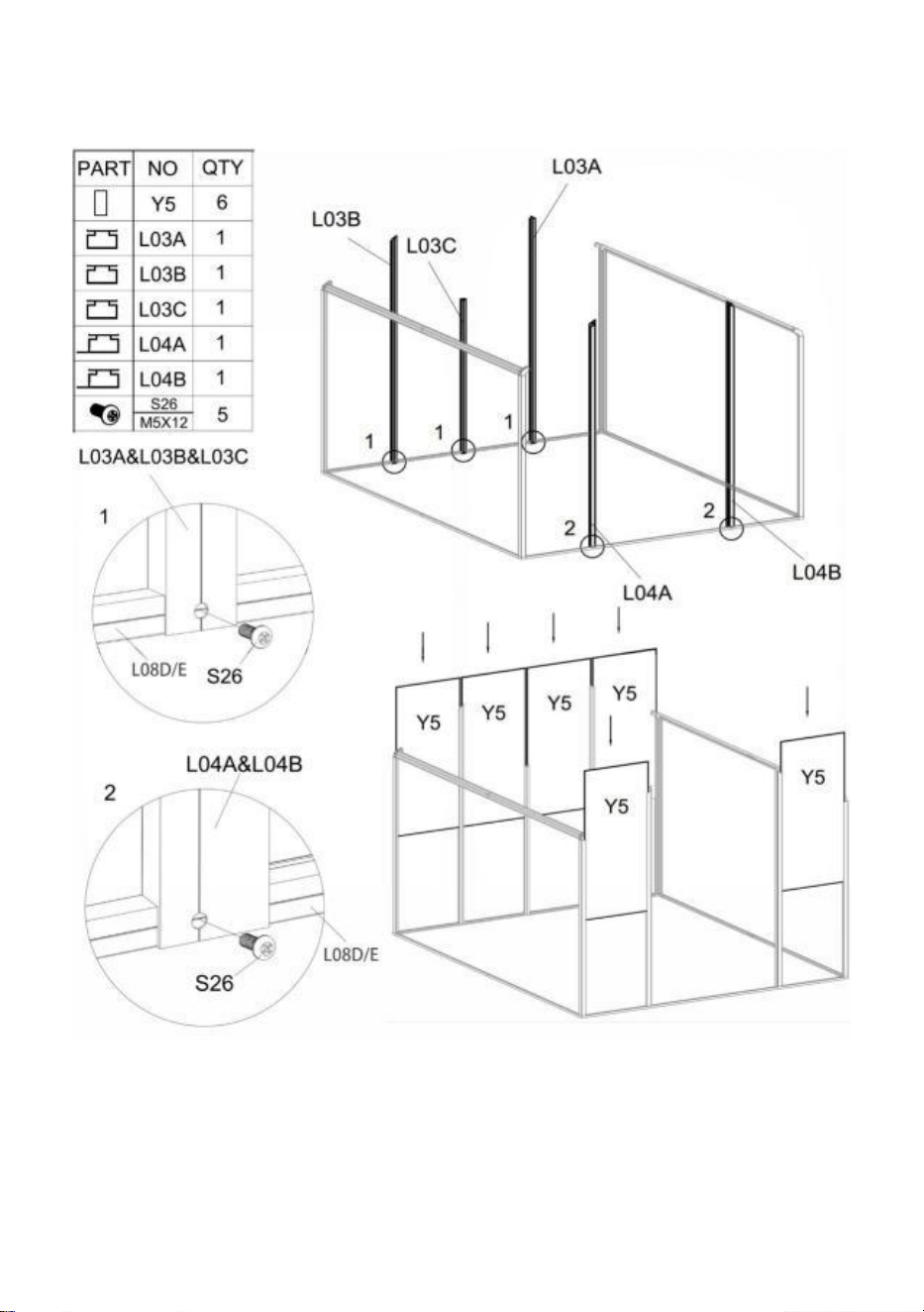
Step 5:
Using Part "S26", install Part "L03A","L03B","L03C","L04A" & "L04B" with the components
completed in last step.
Insert Part "Y5" into the corresponding position as shown.

19
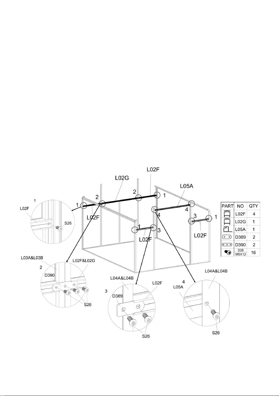
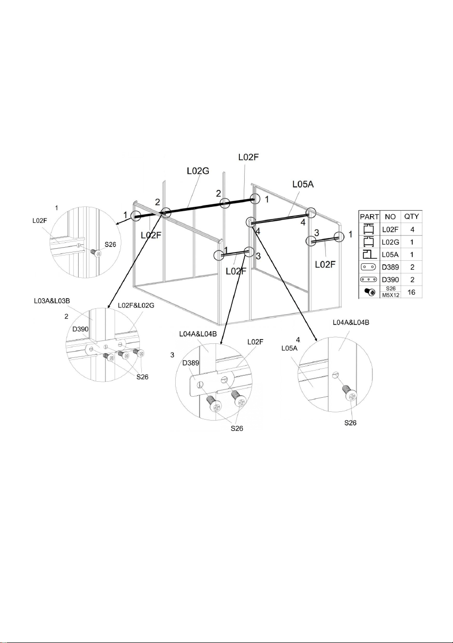
Step 6:
Using Part "S26", install Part "L02F","L02G" & "L05A" with the components completed in
last step.
Detail Figure 1: Using one Part "S26" to connect Part "L02F" & frame.
Detail Figure 2: Using Part "S26" & "D390" to connect Part "L02F" , "L02G" & frame.
Detail Figure 3: Using Part "S26" & "D389" to connect Part "L02F" & frame.
Detail Figure 4: Using one Part "S26" to connect Part "L05A" & frame.
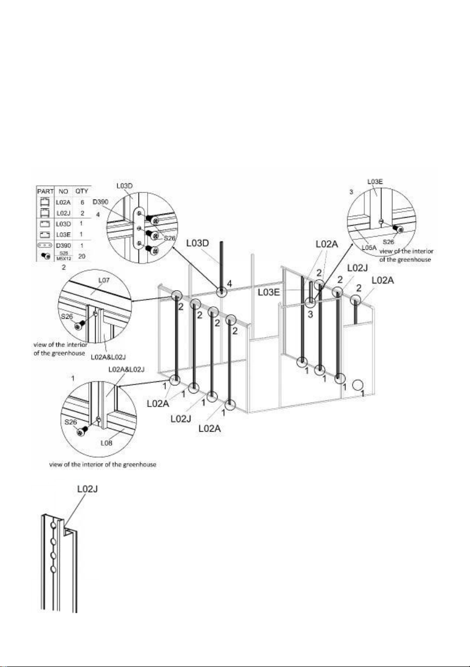
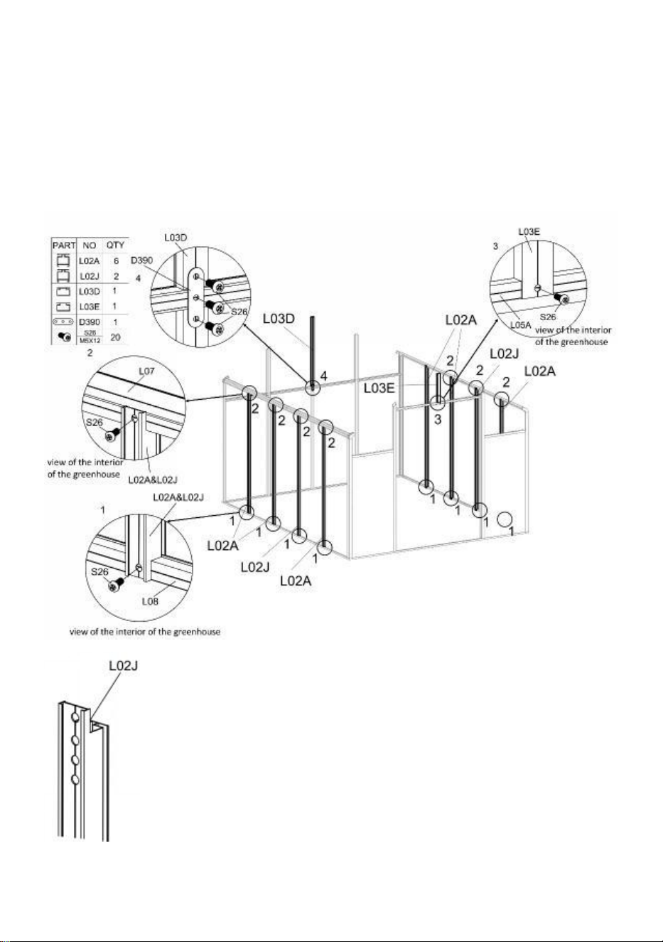
20
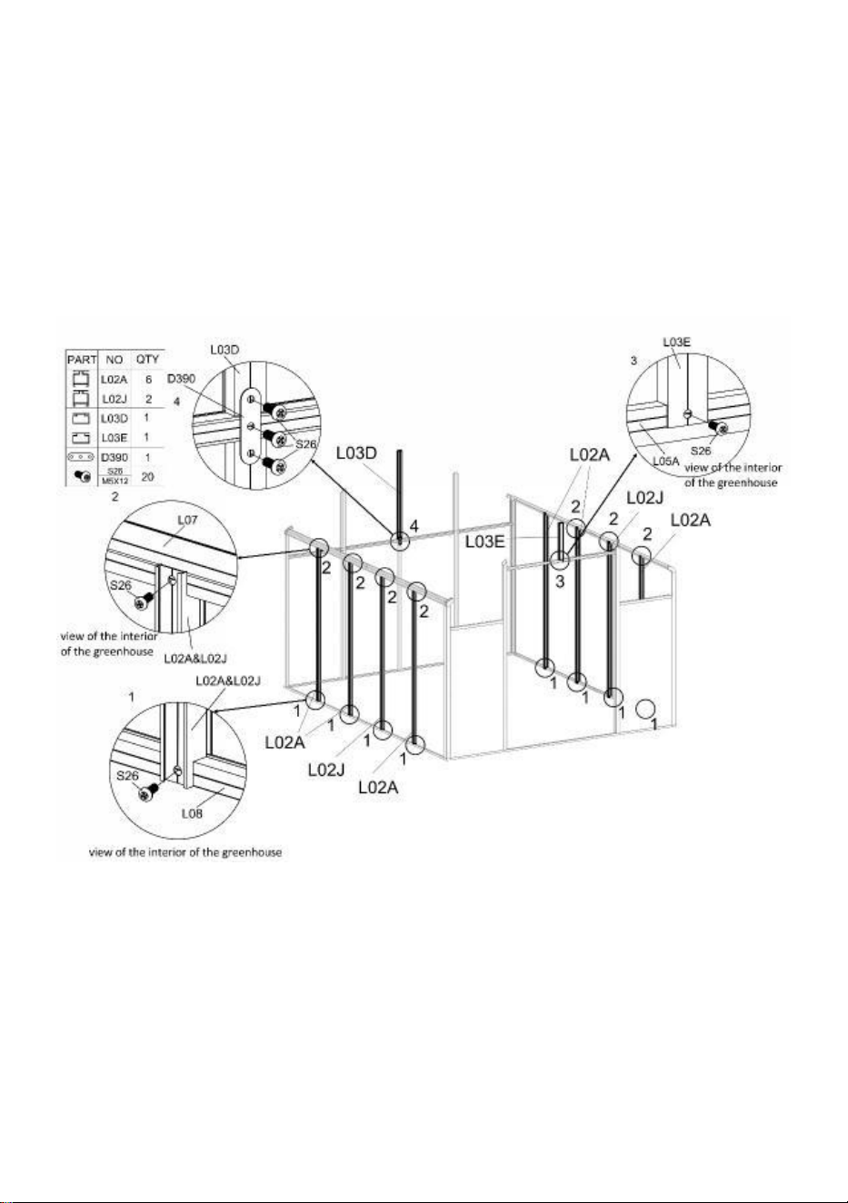
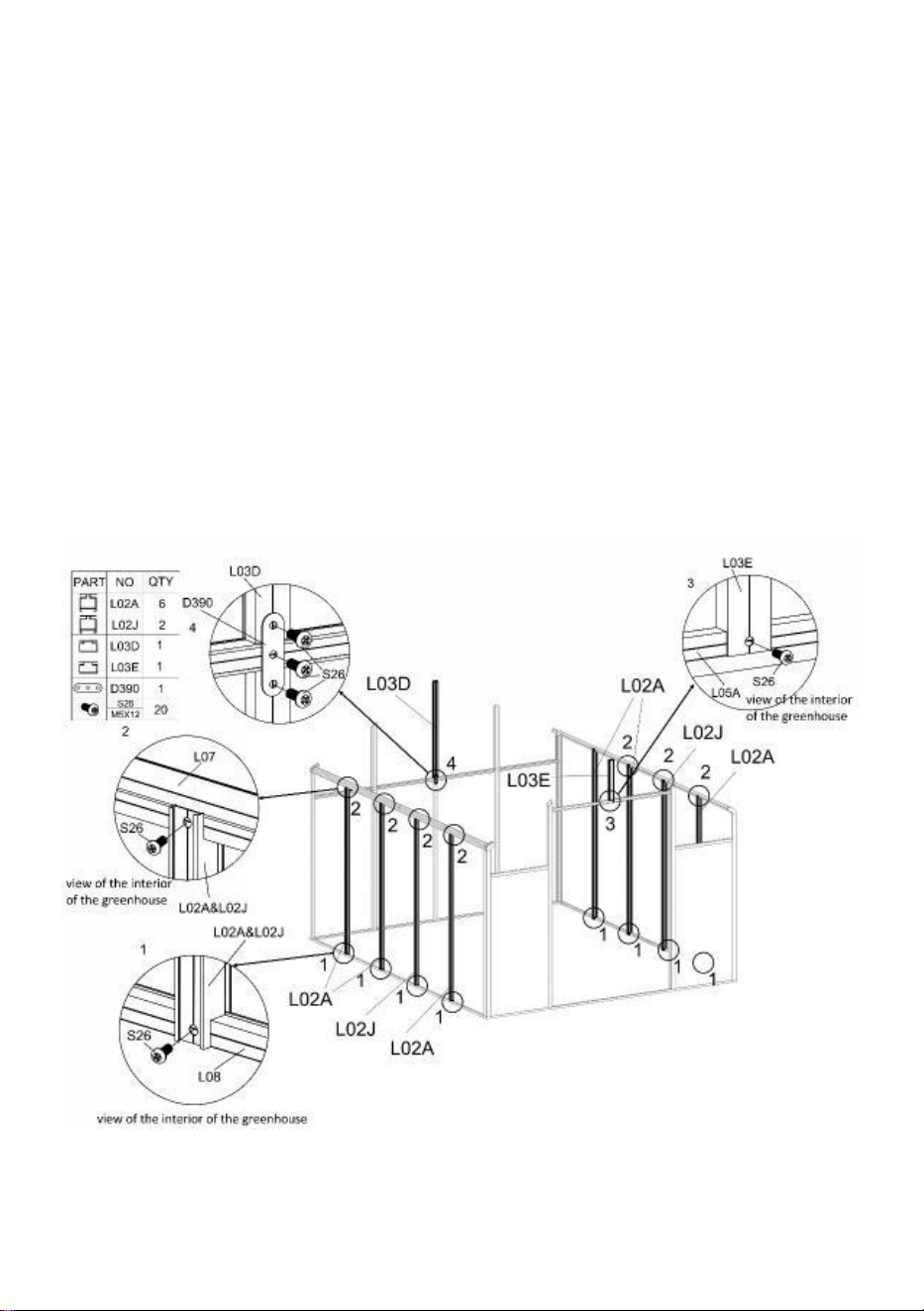
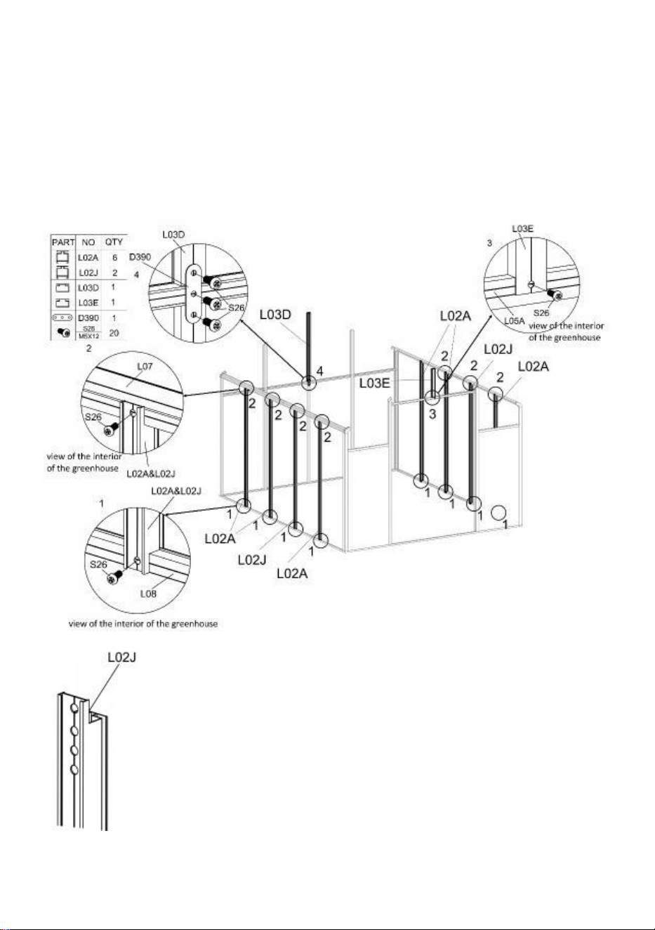
Step 7:
Attention
:
Please be careful to check the position of parts "L02A" and "L02J", which
will affect the subsequent installation of Windows.
Using Part "S26" to connect Part "L02A" or "L02J" & frame.
Using Part "S26" to connect Part "L03E" & frame.
Using Part "S26" & "D390" to connect Part "L03D" & frame.
21
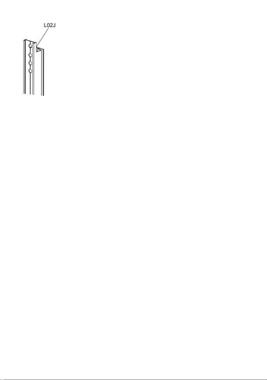
Attention
:
install Part “L02J” with the end with more holes facing upwards.
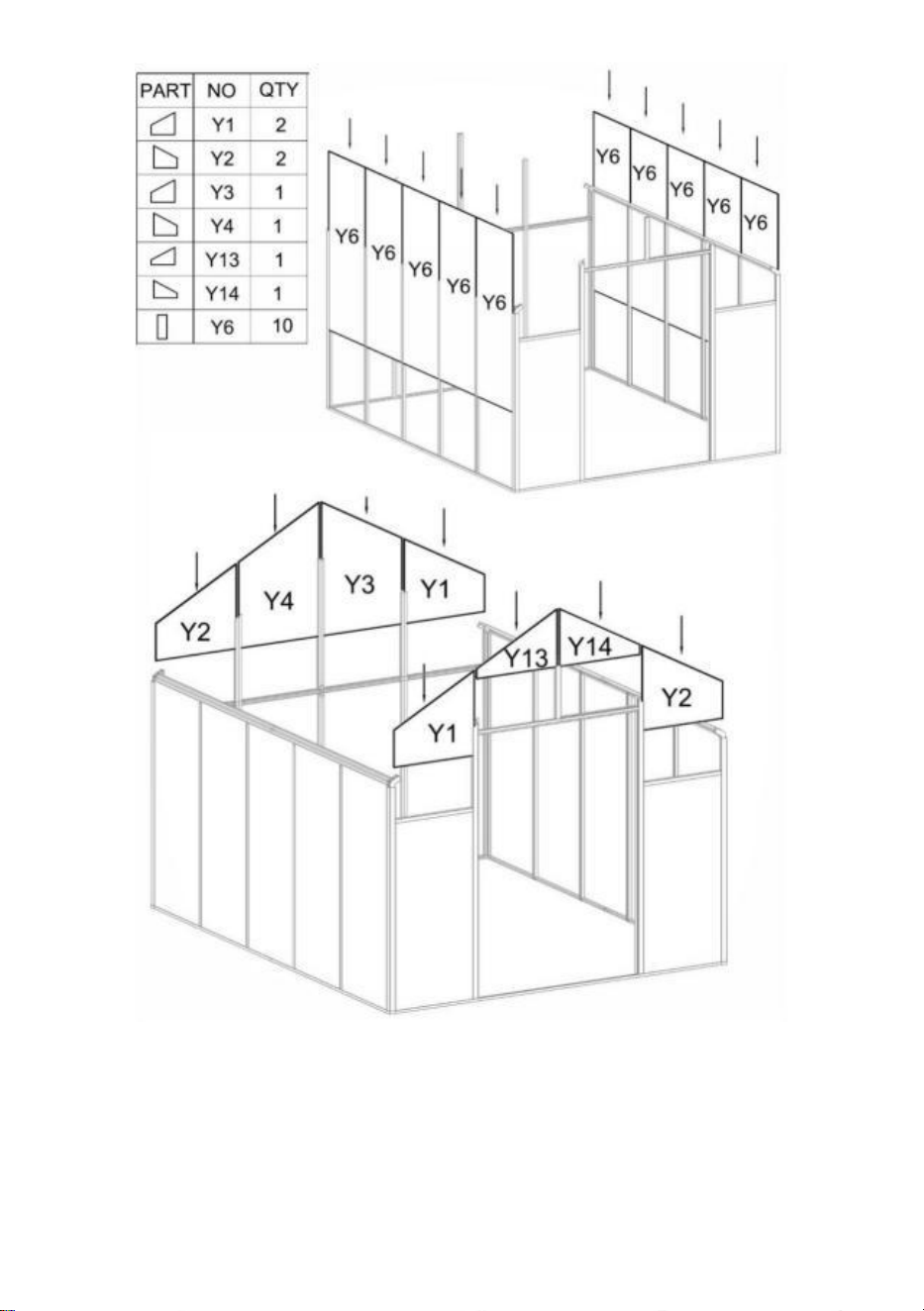
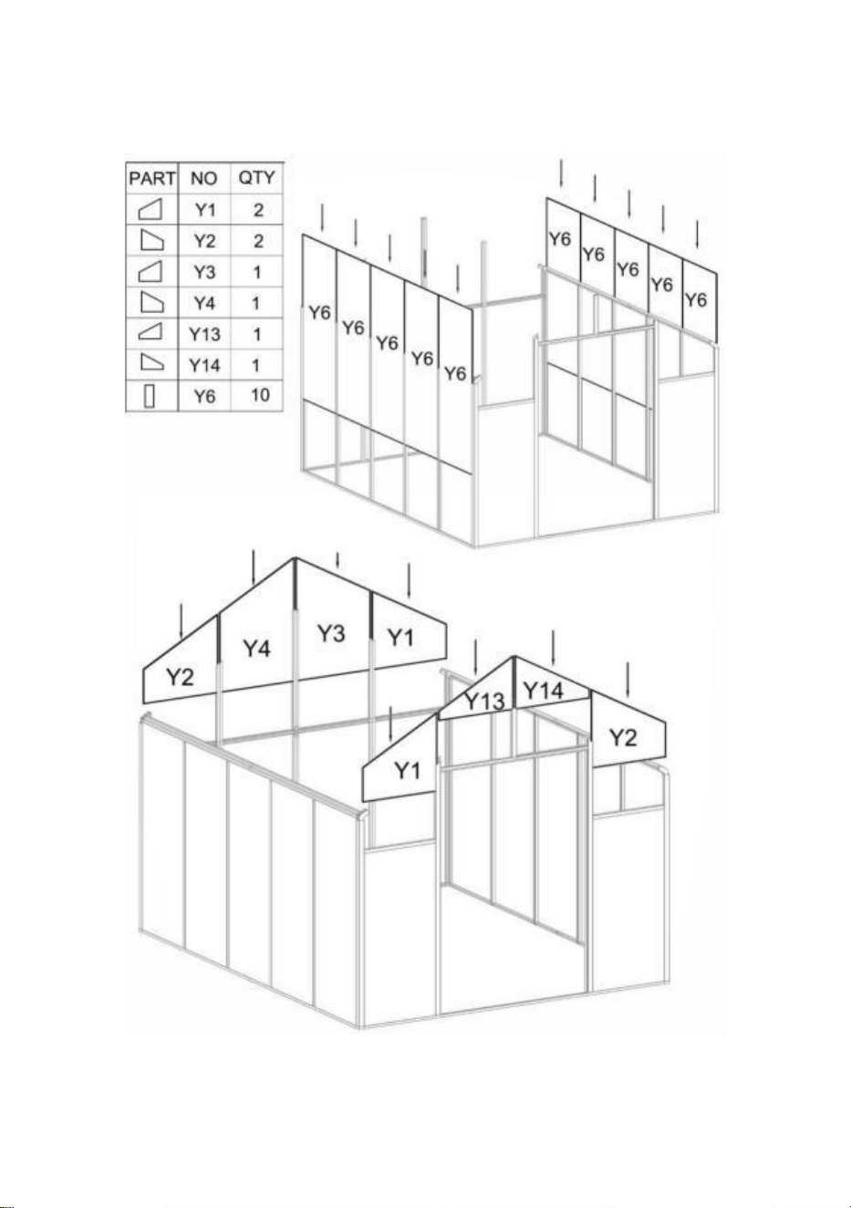
Step 8:
Insert Part "Y1","Y2","Y3","Y4","Y13","Y14" & "Y6"into the corresponding position as shown.

22
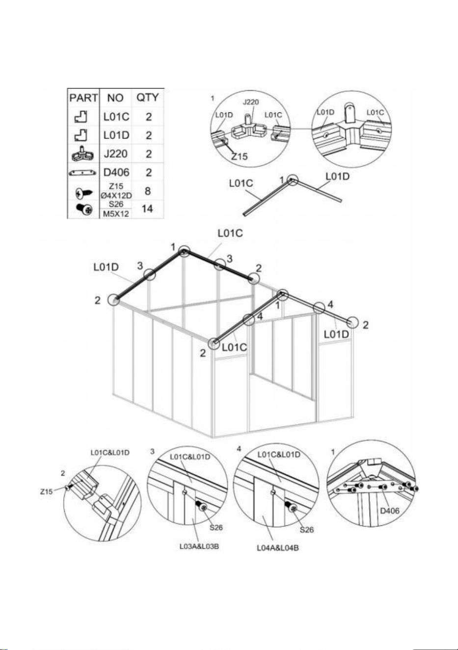
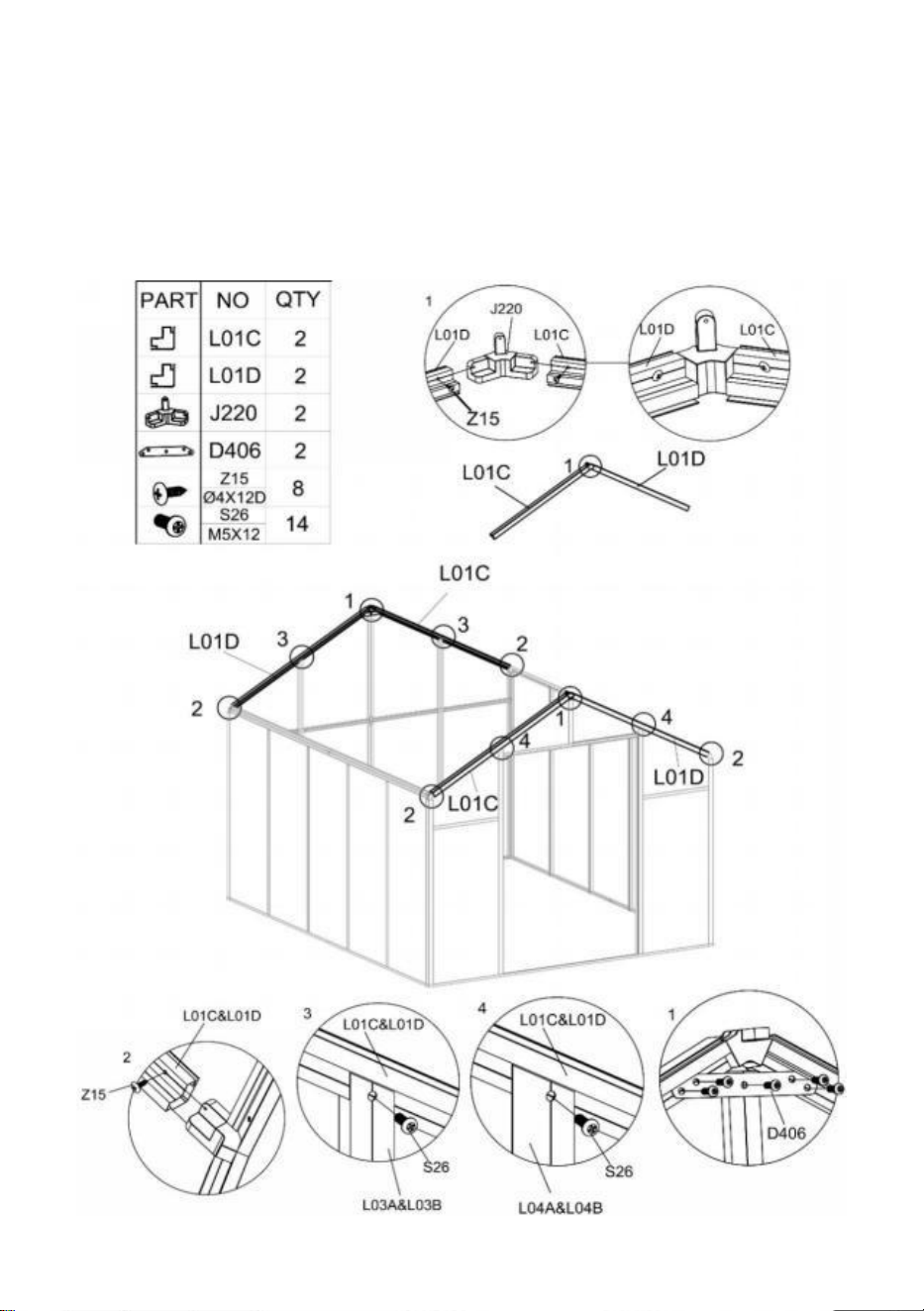
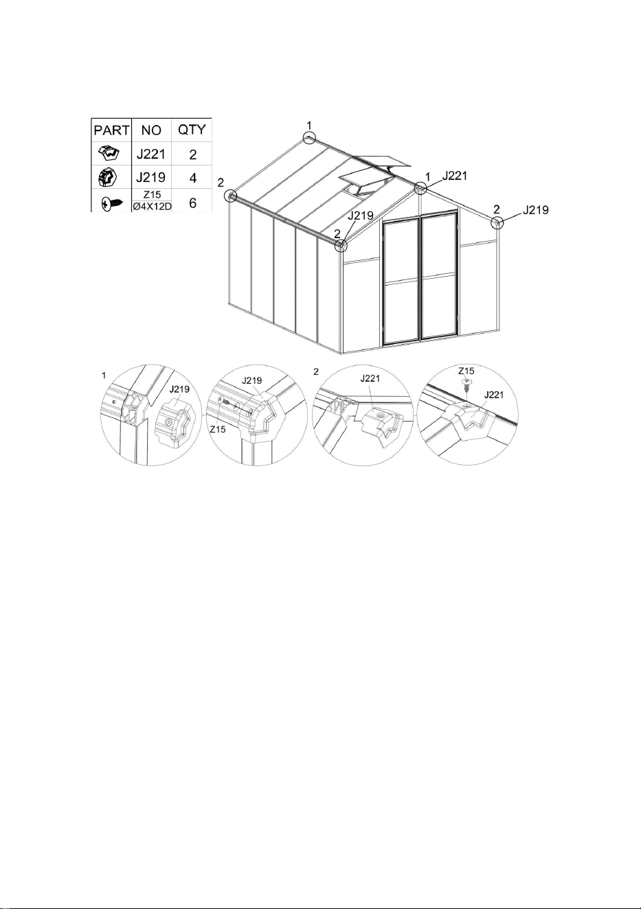
Step 9:
After Parts "L01C" & "L01D" are connected using Part "J220" , they are fixed with Part
"Z15".

23
Install the L01 component on the frame completed in step 8 according to the figure, and use
Part "Z15" and "S26" to lock it after connection.
Install Part "D406" to the component of L01 using Part "S26".
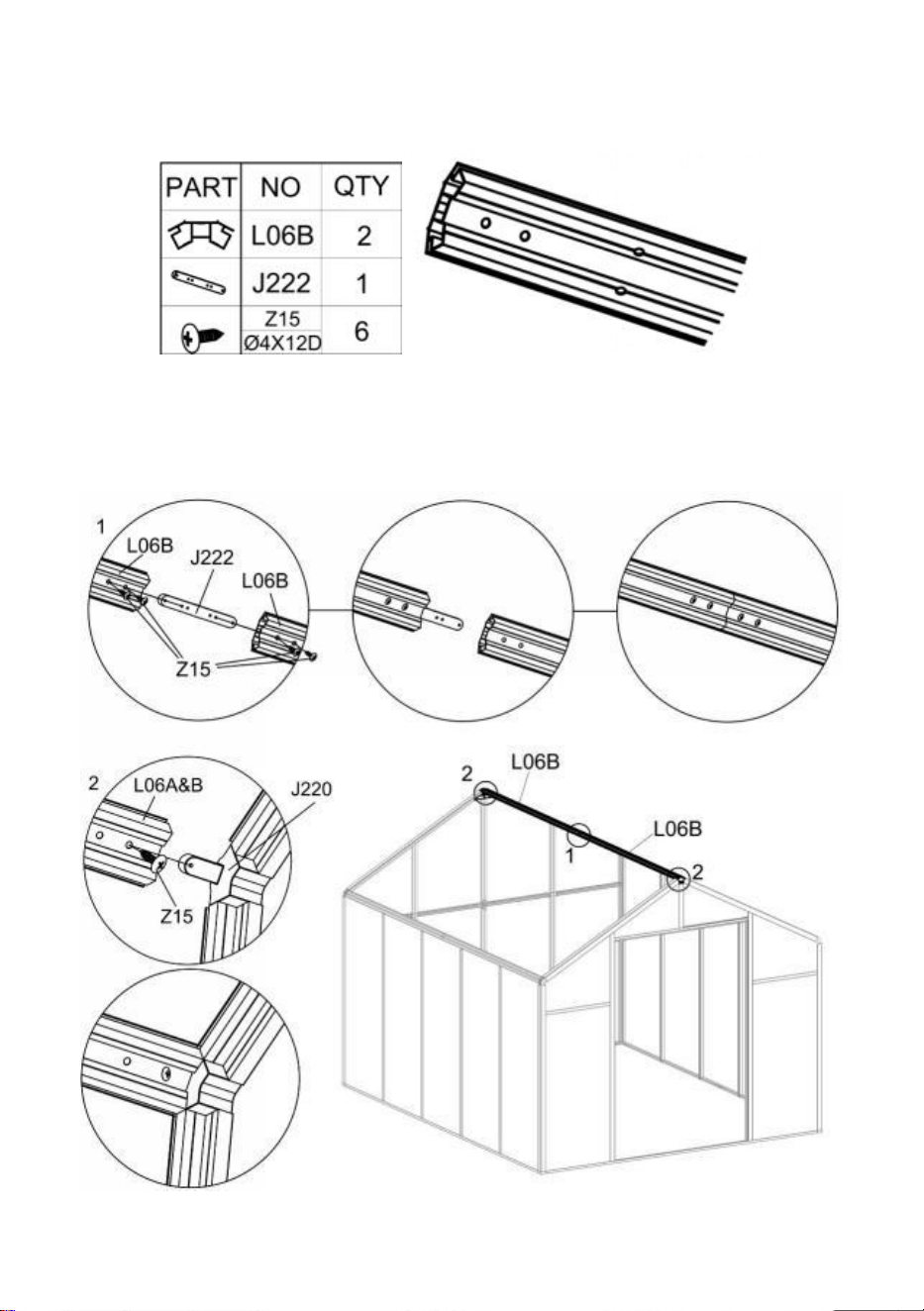
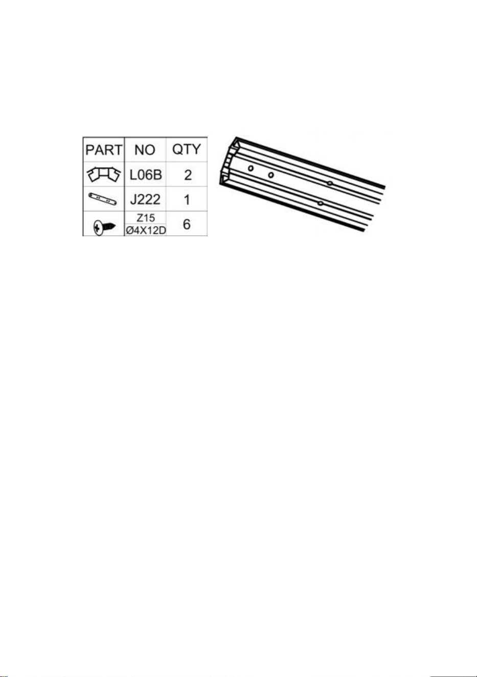
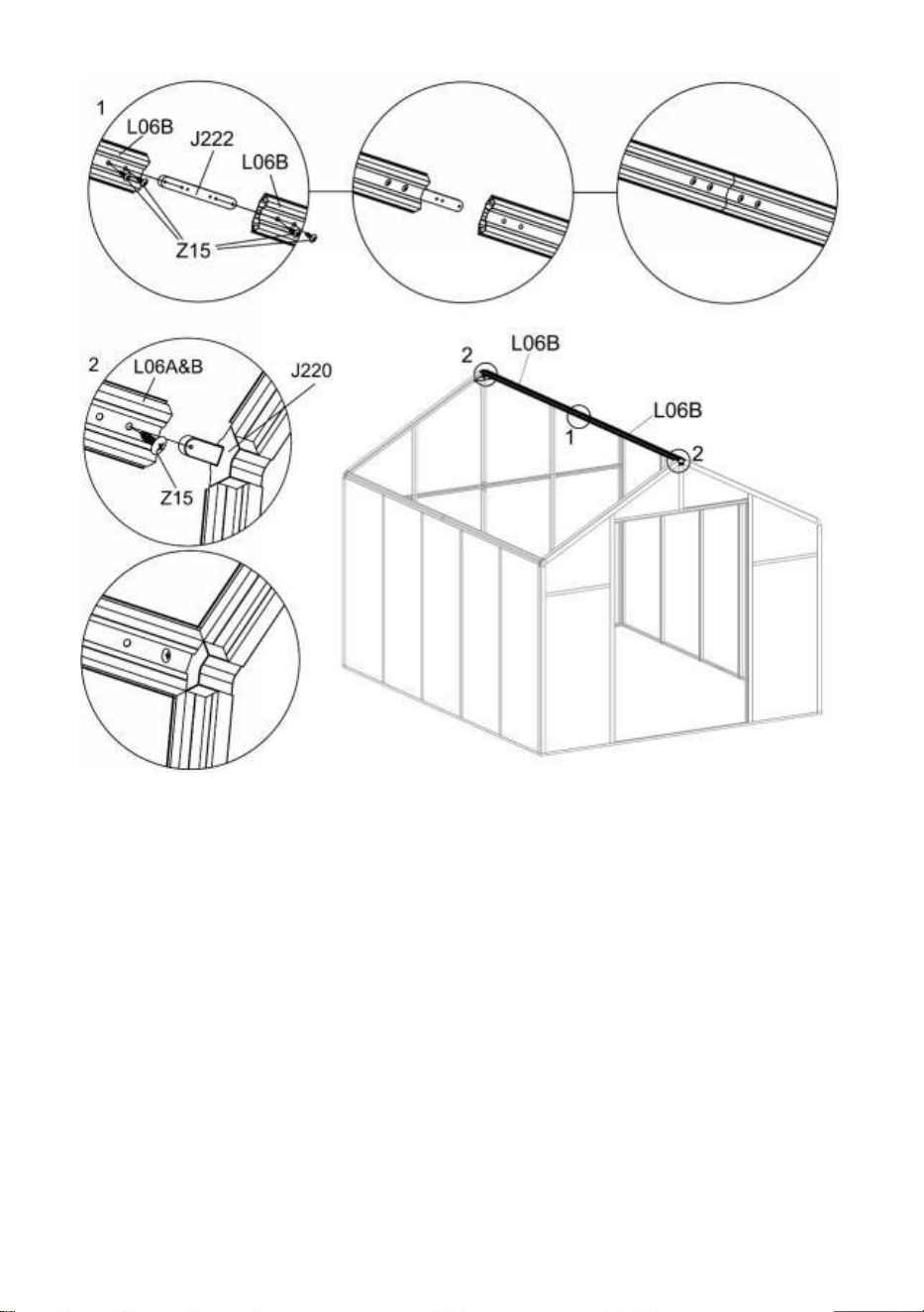
Step 10:
After the two Parts "L06B" are connected using Part "J222" , they are fixed with Part "Z15".
After the installation of the "L06" component, install it on the frame completed in the
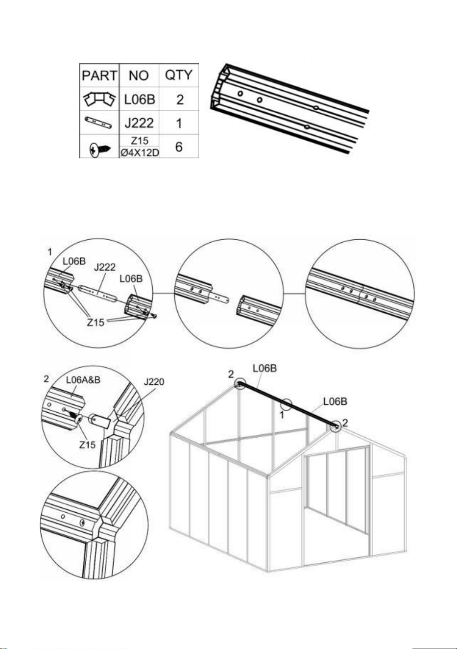
24
previous step according to the figure, and fixed with Part "Z15".
Attention
:
The end of the middle hole of Part “L06” that is closest to the end face is
connected with Part “J222”.
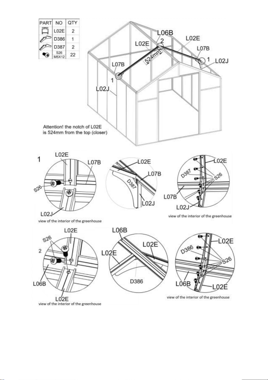
Step 11:
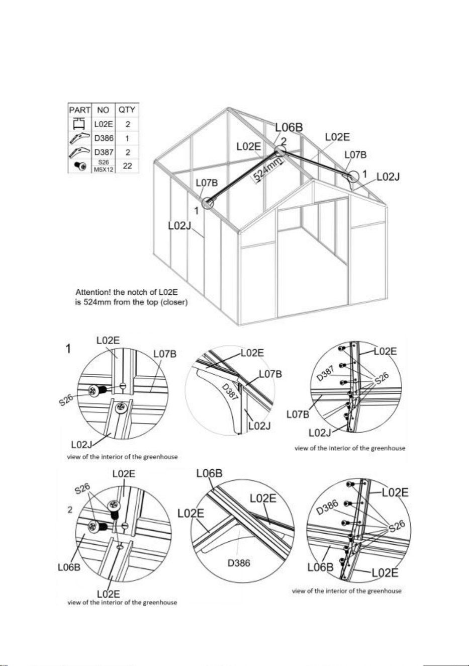
25
In the interior of the greenhouse, place Part "L02E" between parts "L06B" and "L07B"
according to the drawing, and fasten them together with "S26".
Connect Part "L02J" and "L02E" using "D387" with Part "S26".
Connect two Parts "L02E" using "D386" with Part "S26".
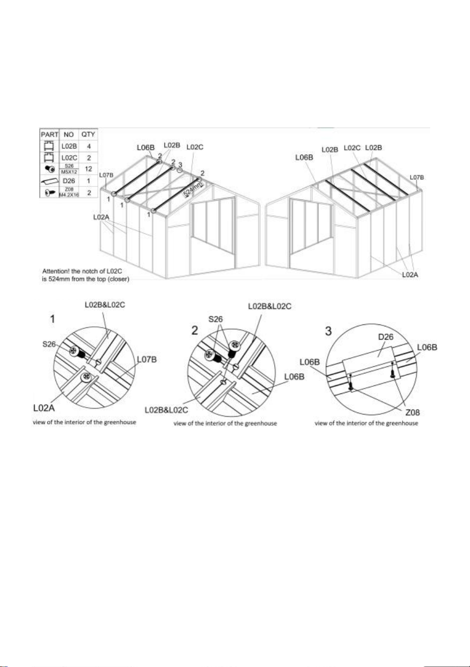
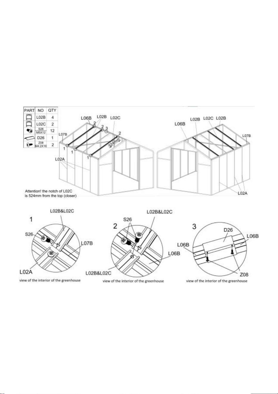
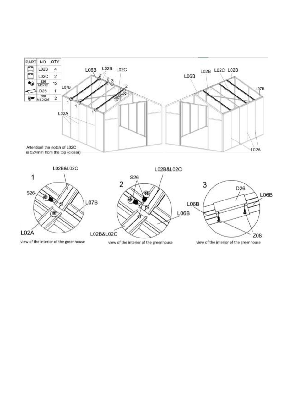
Step 12:
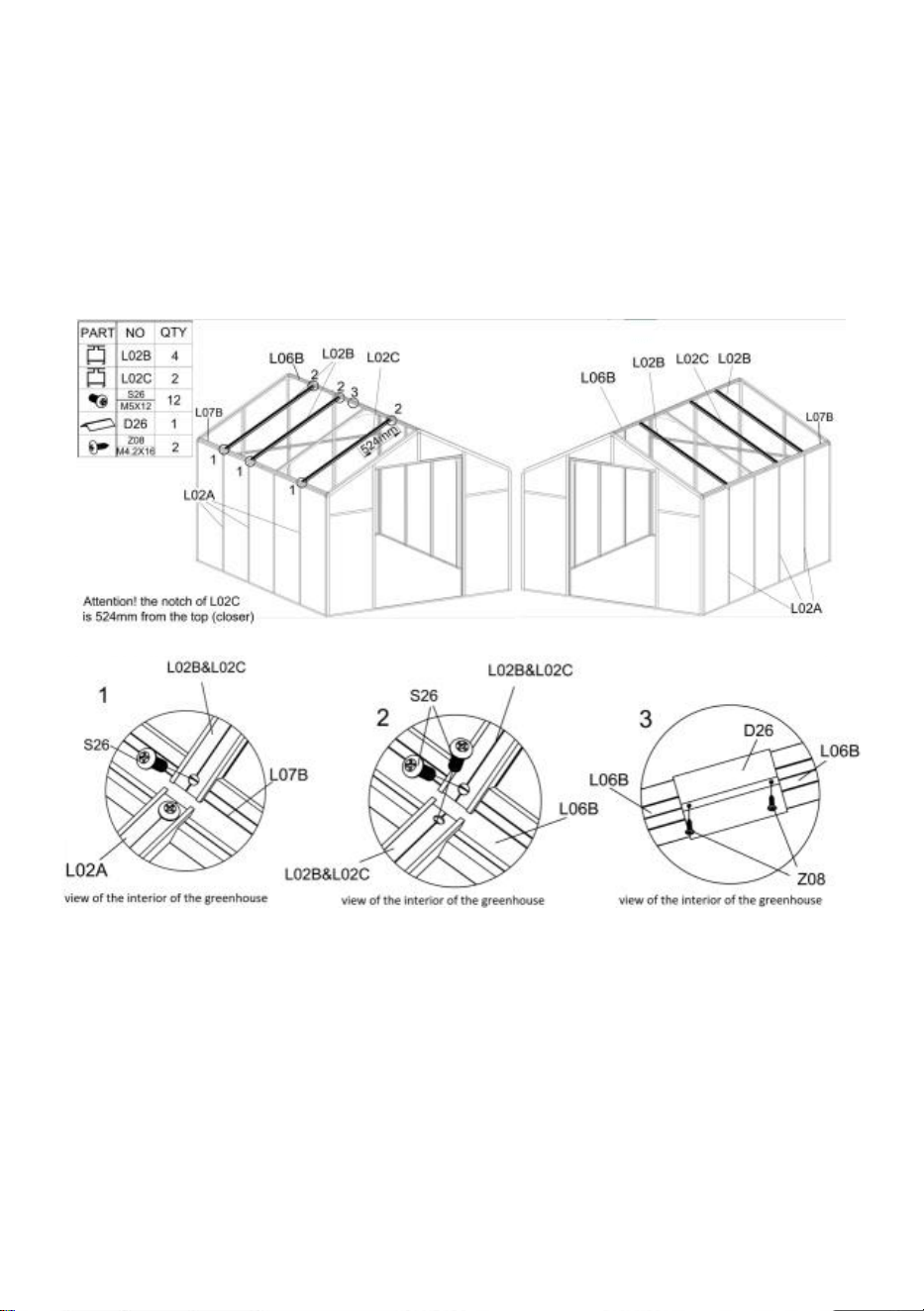
26
In the interior of the greenhouse, place Part "L02B" or "L02C" between parts "L06B" and
"L07B" according to the drawing, and fasten them together with "S26".
Attention
:
Part "L02B" and "L02C" must be installed in accordance with the position shown,
otherwise it will affect the subsequent window assembly!
After the parts "L02B" and "L02C" are firmly installed, use "D26" to connect the two "L06B",
and use "Z08" to secure.
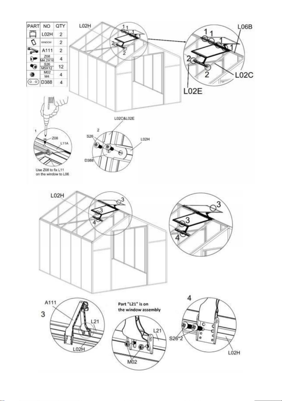
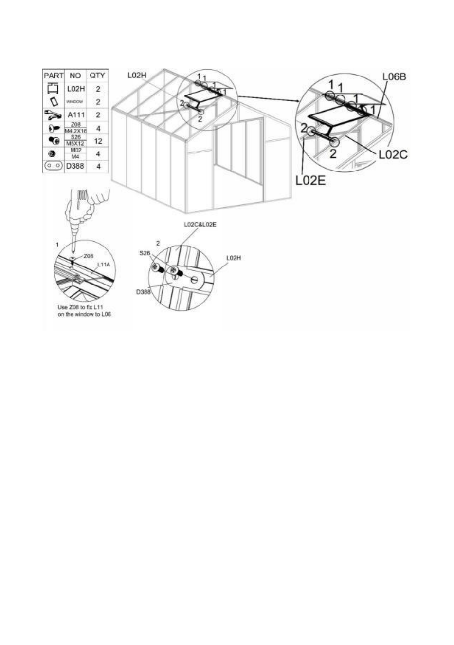
Step 13:
Install the window assembly "L11A" onto the frame completed in Step 12 above using Part
"Z08".
Use Parts "S26" & "D388" to install "L02H" on the frame.
Use the Part "M02" and "S26", and connect the window to the frame with the Part "A111".
Attention
:
When installing Part "A111", open and close the window and lock the screws &
nuts at the same time. Otherwise, the window may not switch smoothly after being fixed.
27
28
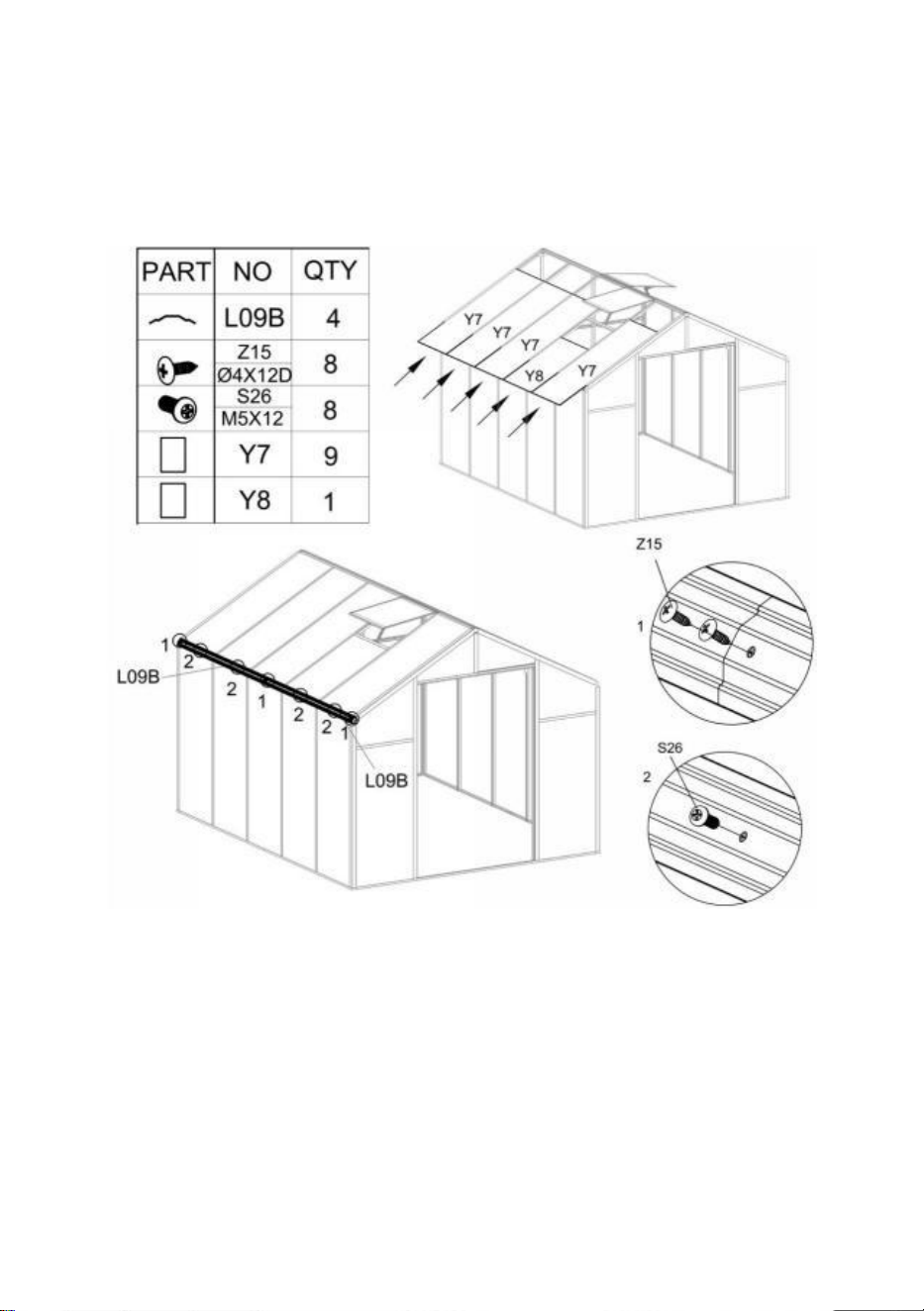
Step 14:
Insert Part "Y7" & "Y8" into the corresponding position as shown.
Use parts "Z15" and "S26" to install "L09B" in the shown position. Note: The screws used in
Figure 1 and 2 will be different.

29
Step 15:
Install "L09B" to the frame using parts "Z15" and "S26".

30
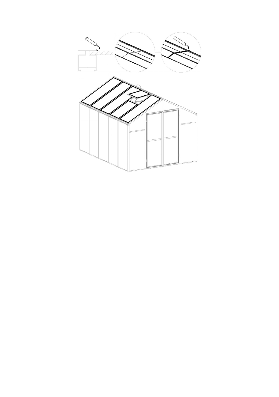
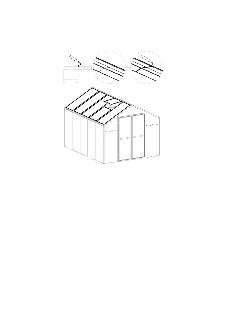
Step 16:
According to customer needs, silicone is applied to the gaps between the aluminum and the
plate at the top of the product, and the gaps between the aluminum to achieve
waterproofing.

31
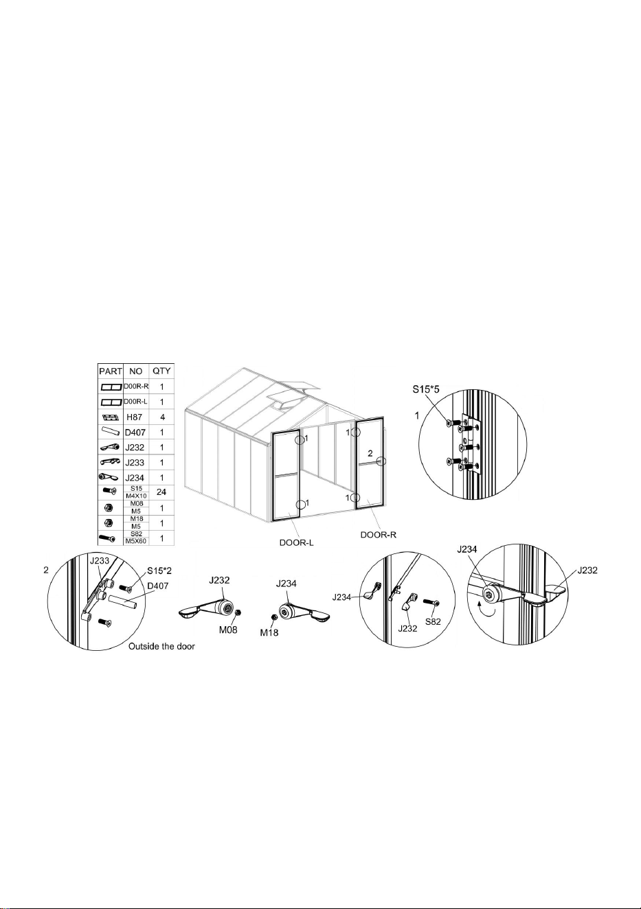
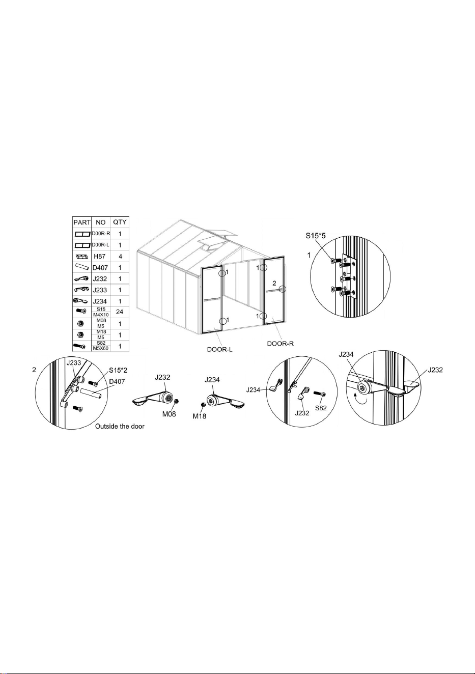
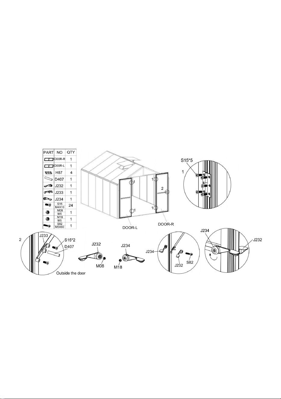
Step 17:
Install the door to the frame using parts "S15" and "H87".
Note: When installing the door, mainly adjust the position, try to open and close the door
during the installation, ensure that the door opens and closes smoothly and then lock the
screws.
Use Part "S15" to install J233 on the outside of the door as shown, then Insert Part "D407"
into the corresponding hole of "J233".
Place the part "M08" and "M18" into the corresponding holes of "J232" and "J234"
respectively.
Use Part "S82" to install "J232" and "J234" on both sides of the door according to the figure.
If Part "J232" and "J234" are still loose after being connected, press "J232" and turn "J234"
clockwise.

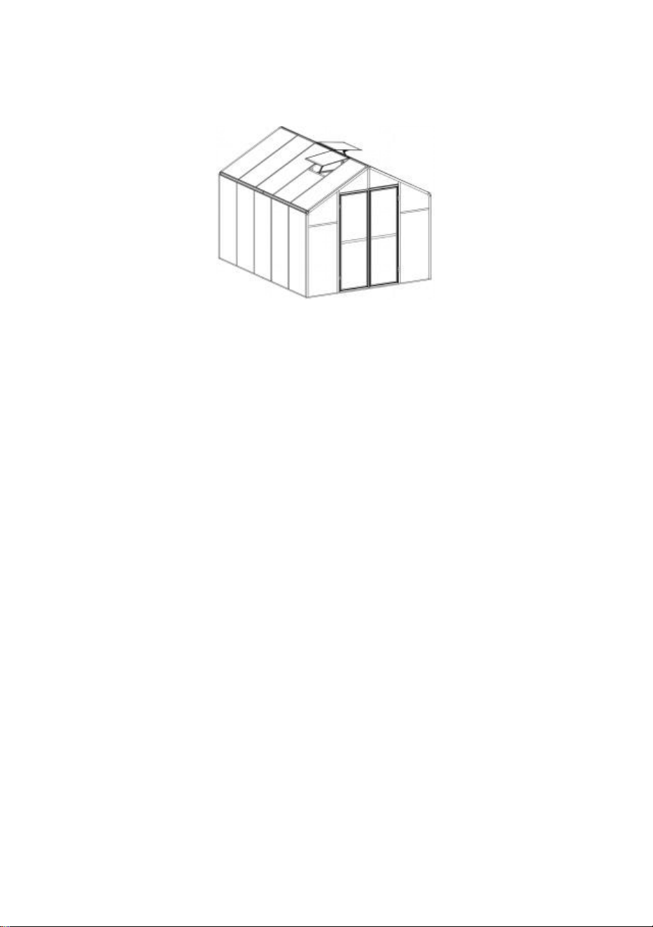
32
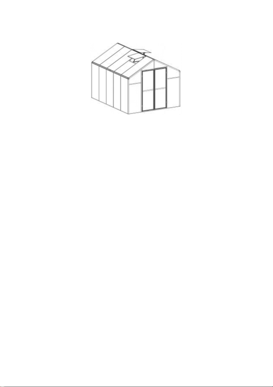
Now, the installation of greenhouse has been completed. Enjoy it!

Manufacturer:Shanghaimuxinmuyeyouxiangongsi
Address: Shuangchenglu 803nong11hao1602A-1609shi, baoshanqu,
shanghai 200000 CN.
Imported to AUS: SIHAO PTY LTD. 1 ROKEVA STREETEASTWOOD
NSW 2122 Australia
Imported to USA: Sanven Technology Ltd. Suite 250, 9166 Anaheim
Place, Rancho Cucamonga, CA 91730


2
Technique Assistance et certificat de garantie électronique
www.vevor.com/support
SERRE EN POLYCARBONATE
UTILISATEUR MANUEL
Nous continuons à nous engager à vous fournir des outils à des prix compétitifs.
"Économisez la moitié", "Moitié prix" ou toute autre expression similaire utilisée uniquement par nous
représente une estimation des économies dont vous pourriez bénéficier en achetant certains outils
avec nous par rapport aux grandes marques et ne signifie pas nécessairement couverture
toutes les catégories d'outils que nous proposons. Nous vous rappelons de bien vouloir vérifier
soigneusement
lorsque vous passez une commande chez nous si vous êtes réellement Économie
Moitié en comparaison avec les plus grandes marques.

3

1

1
Modèle : AM035
BESOIN D'AIDE ? CONTACTEZ-NOUS!
Vous avez des questions sur les produits ? Besoin d'une assistance technique ?
N'hésitez pas à nous contacter :
Assistance technique et certificat de garantie électronique
www.vevor.com/support
Il s'agit des instructions originales, veuillez lire attentivement toutes les
instructions du manuel avant de l'utiliser. VEVOR se réserve une interprétation
claire de notre manuel d'utilisation. L'apparence du produit dépend du produit que
vous avez reçu. Veuillez nous pardonner que nous ne vous informerons plus s'il y
a des mises à jour technologiques ou logicielles sur notre produit.
POLYCARBONATE
GREENHOUSE

2
INSTRUCTIONS
Merci beaucoup d'avoir choisi ce produit . Veuillez lire toutes les instructions avant de
l'utiliser. Les informations vous aideront à obtenir les meilleurs résultats possibles.
VEUILLEZ NOTER! Les dessins de ce manuel sont destinés à titre d'illustration uniquement
et dans certains détails, peut diffèrent du produit réel.
ATTENTION! Lisez tous les avertissements de sécurité et toutes les instructions. Le
non-respect des avertissements et des instructions peut entraîner des blessures graves,
voire la mort. L'appareil ou le produit utilisé dans les instructions d'avertissement fait
référence à la serre en polycarbonate .
Ce produit n'est pas un jouet ni un coffre à jouets. Ne laissez pas les enfants jouer avec cet
article. Veuillez le placer dans une position que les enfants ne peuvent pas grimper pour
éviter les blessures causées par une chute de hauteur .
SÉCURITÉ D'UTILISATION
1. Deux personnes sont nécessaires pour assembler ce produit.
2. Certains composants présentent des bords métalliques coupants. Soyez prudent lorsque
vous manipulez du métal composants. Veuillez porter des gants, des chaussures et des
lunettes de sécurité pendant assemblée.
3. Sélectionnez une zone d'assemblage propre et exempte de tout débris susceptible de
faire trébucher les personnes travaillant sur l'assemblage.
4. Ne grimpez pas et ne vous tenez pas debout sur le toit. Les objets lourds ne doivent pas
être appuyés contre la serre.
5. Prévisualisez les instructions d'assemblage dans votre manuel d'utilisation avant de
continuer.
6. Une fois l'assemblage terminé, inspectez minutieusement la machine pour vous assurer
que tous les écrous, boulons, raccords hydrauliques ou tout autre ensemble de fixations ont
été bien serrés.
67. Ce produit n'est pas une installation de jeu ni une tente et ne doit pas être utilisé à des
fins autres que les serres en polycarbonate.
8. La serre en polycarbonate doit être vérifiée pour s'assurer qu'elle est en bon état de
fonctionnement et qu'elle fonctionne en toute sécurité avant utilisation. Sinon , l'appareil ne
doit pas être utilisé.
9. Nous vous recommandons de placer le cadre inférieur dans une tranchée pré-creusée
après avoir fixé la planche au sol avec des vis d'expansion (incluses) pour une plus grande

3
stabilité et une plus grande résistance au vent de la chambre de température .
10. Il est recommandé d'appliquer de la colle à verre sur la connexion entre le circuit
imprimé et le cadre pour une meilleure protection contre l'eau .
11. Lorsque le temps est mauvais, nous recommandons de retirer les objets précieux de la
serre pour éviter des pertes de biens inutiles et de ne pas utiliser la serre pendant cette
période .
12. Gardez le toit exempt de neige et de feuilles. Laisser la neige s'accumuler sur le toit
peut endommager le produit.
A vant d'utiliser le produit - si vous avez des questions concernant le montage ou le
fonctionnement correct, contactez votre revendeur ou représentant.
14. Lorsque votre produit a besoin d'être nettoyé, utilisez une solution détergente douce et
rincez à l'eau froide et propre. N'utilisez pas d'acétone, de nettoyants abrasifs ou de
détergents puissants pour nettoyer les panneaux.
CONSERVEZ CES INSTRUCTIONS
PARAMÈTRES TECHNIQUES
Modèle
AM035
Couleur
Aluminium noir
Matériel
Aluminium , Feuille de polycarbonate
Taille du produit
236*289*206cm

4
Liste des pièces
5

6
7
Liste des cartes PC
Si la pièce en aluminium est courbée comme sur la photo ci-dessous, veuillez utiliser la clé

8
pour la restaurer.
Retirez environ 2 pouces de film de tous les bords de la feuille avant l'installation et retirez
tout le film immédiatement une fois la construction terminée. Veuillez vous assurer que le
côté avec le film blanc est tourné vers l'extérieur.
Attention : La plupart des pièces "S26" sont installées sur l'aluminium, et doivent être
retirées avant l'installation selon les instructions.

9
Distribution de cartes PC
10
Assemblage de la porte gauche
11
Étape 1 :
Assemblez les pièces "L17B", "L16A" et "L16B" avec la pièce "S26" comme indiqué sur la
figure. Placez la pièce "Y11" dans le cadre.
Étape 2 :
Placez la pièce « J228 » dans la position correspondante de la pièce « L18D » selon
l'image et utilisez la pièce « Z15 » pour la fixer.
Étape 3 :
Installez le composant « L18 » assemblé à l'étape 2 dans le cadre selon la figure. Une fois
le composant assemblé en place, fixez-le à l'aide de la pièce « Z15 ».

12
Assemblage de la porte droite
Étape 1 :
Assemblez les pièces "L17 A ", "L16A" et "L16 A " avec la pièce "S26" comme indiqué sur la
figure. Placez la pièce "Y11" dans le cadre.
Étape 2 :
Placez la pièce "J228" dans la position correspondante de la pièce "L18 B " et "L18 C "
selon l'image, et utilisez la pièce "Z15" pour le réparer.
Étape 3 :
Installez le composant « L18 » assemblé à l'étape 2 dans le cadre selon la figure. Une fois
le composant assemblé en place, fixez-le à l'aide de la pièce « Z15 ».

13
Assemblage de fenêtre
Étape 1 :
Faites glisser la pièce "S28" dans la pièce "L21" comme indiqué sur la figure. Assemblez
ensuite les pièces "L20", "L21" et "Y10" ensemble.
Étape 2 :
Utilisez la pièce "Z15" pour assembler la pièce "L19" avec les composants complétés à
l'étape précédente.
Étape 3 :
Utilisez la pièce "Z15" pour assembler la pièce "L11A" avec les composants complétés à
l'étape 2.
Attention : il y a 2 fenêtres au total.

14

15
Assemblage de serre
Étape 1 :
Veuillez vous référer à l'image pour connaître l'emplacement des pièces requises pour
l'installation à cette étape.
Coin : Assemblez les pièces "J217" et "L08" à l'aide de la pièce "Z15" .
Connexion de la barre en aluminium : Une fois les deux barres en aluminium connectées à
l'aide de la pièce « J222 » , ils sont fixés avec la pièce "Z15".
Étape 2 :
16
Si vous envisagez de fixer votre serre à un sol solide, vous pouvez suivre cette étape pour
rendre votre serre plus sécurisée.
La position d'installation du connecteur pièce « D410 » est illustrée dans la figure suivante.
Si vous envisagez de fixer la serre au plancher de bois, référez-vous à la figure ci-dessous
pour relier le plancher de bois à la serre à l'aide de la pièce « D410 ». , "Z08" et "Z26".
Si vous envisagez de l'installer sur un sol solide , comme du béton. Veuillez d'abord
déterminer l'emplacement du trou à percer, utilisez l'outil électrique pour percer le trou de 8
17
mm de diamètre, utilisez un marteau ou un outil similaire pour enfoncer la pièce "J129"
dans le sol, et enfin utilisez la pièce "D410", "Z26". & "Z08" pour relier le sol à la serre.
Étape 3 :
Assemblez les pièces « L01A » , « L01B » , « L01E » et « L01F » aux composants
complétés à l'étape 1 à l'aide de la pièce « Z15 » .
18
Étape 4 :
Après les deux parties " L07B " sont connectés à l'aide de la pièce "J222" , ils sont fixés
avec la pièce "Z15". Une fois les deux pièces "L07B" connectées, installez-les avec la pièce
"J218" selon la fin du schéma et fixez-les avec la pièce "Z15".

19
Après l'installation du composant "L07", installez-le sur le châssis réalisé à l'étape
précédente selon la figure.
Étape 5 :
À l'aide de la pièce « S26 », installez la pièce " L03A " , " L03B " , " L03C " , " L04A " et "
L04B " avec les composants complétés à la dernière étape .
Insérez la pièce « Y5 » dans la position correspondante, comme indiqué.

20
Étape 6 :
À l'aide de la pièce « S26 », installez la pièce " L02F " , " L02G " et " L05A " avec les
composants complétés à la dernière étape .

21
Détail Figure 1 : Utilisation d'une pièce « S26 » pour connecter la pièce « L02F » et le
cadre.
Détail Figure 2 : Utilisation des pièces « S26 » et « D390 » pour connecter les pièces «
L02F » , « L02G » et le cadre.
Détail Figure 3 : Utilisation des pièces « S26 » et « D389 » pour connecter la pièce « L02F »
et le cadre.
Détail Figure 4 : Utilisation d'une pièce « S26 » pour connecter la pièce « L05A » et le
cadre.
22
Étape 7 :
Attention : veillez à vérifier la position des pièces « L02A » et « L02J », ce qui
affectera l'installation ultérieure de Windows.
Utilisation de la pièce « S26 » pour connecter la pièce « L02A » ou « L02J » et le cadre.
Utilisation de la pièce « S26 » pour connecter la pièce « L03E » et le cadre.
Utilisation des pièces « S26 » et « D390 » pour connecter la pièce « L03D » et le cadre.
Attention : installez la pièce « L02J » avec l'extrémité avec plus de trous tournée

23
vers le haut.
Étape 8 :
Insérez les pièces "Y 1 " , " Y 2 " , " Y 3 " , " Y 4 " , " Y 13 " , " Y 14 " et " Y 6 " dans la position
correspondante comme indiqué.

24
Étape 9 :
Après les parties « L01C » et « L01D » sont connectés à l'aide de la pièce "J22 0 " , ils sont
fixés avec la pièce "Z15".
Installez le composant L01 sur le cadre terminé à l'étape 8 selon la figure, et utilisez les
pièces "Z15" et "S26" pour le verrouiller après la connexion.
Installez la pièce « D406 » sur le composant de L01 à l'aide de la pièce « S26 ».

25
Étape 10 :
Après les deux parties " L06B " sont connectés à l'aide de la pièce "J222" , ils sont fixés
avec la pièce "Z15".
Après l'installation du composant "L0 6 ", installez-le sur le châssis réalisé à l'étape
précédente selon la figure , et fixé avec la pièce "Z15".

26
Attention : l'extrémité du trou central de la pièce « L06 » qui est la plus proche de la
face d'extrémité est reliée à la pièce « J222 » .
Étape 11 :
A l'intérieur de la serre, placez la pièce "L02E" entre les pièces "L06B" et "L07B" selon le
dessin et fixez-les ensemble avec "S26".

27
Connectez les pièces "L02J" et "L02E" en utilisant "D387" avec la pièce "S26".
Connectez deux parties "L02 E " en utilisant "D38 6 " avec la partie "S26".
Étape 1 2 :
A l'intérieur de la serre, placez la pièce "L02 B " ou "L02 C " entre les pièces "L06B" et
"L07B" selon le dessin, et fixez-les ensemble avec "S26".
28
Attention
:
Les pièces « L02B » et « L02C » doivent être installées conformément à la
position indiquée, sinon cela affectera le montage ultérieur de la fenêtre !
Une fois les pièces « L02B » et « L02C » fermement installées, utilisez « D26 » pour
connecter les deux « L06B » et utilisez « Z08 » pour sécuriser.
Étape 1 3 :
Installez l'assemblage de fenêtre « L11A » sur le cadre terminé à l'étape 12 ci-dessus à
l'aide de la pièce « Z08 ».
Utilisez les pièces "S26" et "D388" pour installer "L02H" sur le cadre.
Utilisez les pièces "M02" et "S26", et connectez la fenêtre au cadre avec la pièce "A111".
Attention
:
Lors de l'installation de la pièce « A111 » , ouvrez et fermez la fenêtre et
verrouillez les vis et les écrous en même temps. Sinon, la fenêtre risque de ne pas basculer
en douceur après avoir été réparée.

29

30
Étape 1 4 :
Insérez les pièces "Y 7 " et "Y 8 " dans la position correspondante comme indiqué.
Utilisez les pièces "Z15" et "S26" pour installer "L09B" dans la position indiquée. Remarque :
Les vis utilisées dans les figures 1 et 2 seront différentes.

31
Étape 1 5 :
Installez "L09B" sur le cadre à l'aide des pièces "Z15" et "S26".

32
Étape 1 6 :
Selon les besoins du client, du silicone est appliqué sur les espaces entre l'aluminium et la
plaque en haut du produit, ainsi que sur les espaces entre l'aluminium pour réaliser
l'étanchéité.
33
Étape 1 7 :
Installez la porte sur le cadre à l'aide des pièces " S 15" et " H87 ".
Note: Lors de l'installation de la porte, ajustez principalement la position, essayez d'ouvrir et
de fermer la porte pendant l'installation, assurez-vous que la porte s'ouvre et se ferme en
douceur, puis verrouillez les vis.
Utilisez la pièce "S15" pour installer J233 à l'extérieur de la porte comme indiqué , puis
insérez la pièce "D407" dans le trou correspondant de "J233".
Placez les pièces "M08" et "M18" dans les trous correspondants de "J232" et "J234"
respectivement.
Utilisez la pièce "S82" pour installer "J232" et "J234" des deux côtés de la porte selon la
figure. Si les pièces « J232 » et « J234 » sont toujours desserrées après avoir été
connectées, appuyez sur « J232 » et tournez « J234 » dans le sens des aiguilles d'une
montre.
34
Aujourd’hui, l’installation de la serre est terminée. Profitez -en !

Fabricant : Shanghaimuxinmuyeyouxiangongsi
Adresse : Shuangchenglu 803nong11hao1602A-1609shi, baoshanqu,
Shanghai 200000 CN.
Importé en Australie : SIHAO PTY LTD. 1 ROKEVA STREETASTWOOD
NSW 2122 Australie
Importé aux États-Unis : Sanven Technology Ltd. Suite 250, 9166
Anaheim
Lieu, Rancho Cucamonga, CA 91730


2
Technisch Support und E-Garantie-Zertifikat
www.vevor.com/support
POLYCARBONAT-GEWÄCHSHAUS
BENUTZER HANDBUCH
Wir sind weiterhin bestrebt, Ihnen Werkzeuge zu wettbewerbsfähigen Preisen anzubieten.
"Sparen Sie die Hälfte", "Halber Preis" oder andere ähnliche Ausdrücke, die wir nur verwenden
stellt eine Schätzung der Einsparungen dar, die Sie durch den Kauf bestimmter Werkzeuge erzielen
können
mit uns im Vergleich zu den großen Top-Marken und bedeutet nicht unbedingt, Abdeckung
alle von uns angebotenen Werkzeugkategorien. Wir möchten Sie bitten, zu überprüfen sorgfältig
wenn Sie bei uns eine Bestellung aufgeben, wenn Sie tatsächlich Speichern
Hälfte im Vergleich mit den Top-Großmarken.

3

1

1
Modell: AM035
Brauchen Sie Hilfe? Kontaktieren Sie uns!
Sie haben Fragen zu unseren Produkten? Sie benötigen technischen Support?
Dann kontaktieren Sie uns gerne:
Technischer Support und E-Garantie-Zertifikat
www.vevor.com/support
Dies ist die Originalanleitung. Bitte lesen Sie alle Anweisungen sorgfältig durch,
bevor Sie das Gerät in Betrieb nehmen. VEVOR behält sich eine klare Auslegung
unserer Bedienungsanleitung vor. Das Erscheinungsbild des Produkts richtet sich
nach dem Produkt, das Sie erhalten haben. Bitte verzeihen Sie uns, dass wir Sie
nicht erneut informieren, wenn es Technologie- oder Software-Updates für unser
Produkt gibt .
POLYCARBONATE
GREENHOUSE

2
ANWEISUNGEN
Vielen Dank, dass Sie sich für dieses Produkt entschieden haben . Bitte lesen Sie vor der
Verwendung alle Anweisungen sorgfältig durch. Die Informationen helfen Ihnen, die
bestmöglichen Ergebnisse zu erzielen.
BITTE BEACHTEN! Die Zeichnungen in diesem Handbuch dienen dienen lediglich
Illustrationszwecken und können in einigen vom tatsächlichen Produkt abweichen.
ACHTUNG! Lesen Sie alle Sicherheitshinweise und Anweisungen. Die Nichtbeachtung der
Hinweise und Anweisungen kann zu schweren Verletzungen oder sogar zum Tod führen.
Das in den Warnhinweisen verwendete Gerät oder Produkt bezieht sich auf
Gewächshäuser aus Polycarbonat .
Dieses Produkt ist kein Spielzeug und auch keine Spielzeugkiste. Erlauben Sie Kindern
nicht, mit diesem Artikel zu spielen. Bitte stellen Sie es an einer Stelle auf, an der Kinder
nicht hochklettern können, um Verletzungen durch Stürze aus großer Höhe zu vermeiden .
SICHERHEIT BEI DER VERWENDUNG
1. Für die Montage dieses Produkts sind zwei Personen erforderlich.
2. Einige Komponenten haben scharfe Metallkanten. Bitte seien Sie vorsichtig beim
Umgang mit Metall Komponenten. Bitte tragen Sie Handschuhe, Schuhe und Schutzbrille
während Montage.
3. Wählen Sie für die Montage einen Bereich aus, der sauber und frei von Fremdkörpern
ist , über die an der Montage arbeitende Personen stolpern könnten.
4. Klettern oder stehen Sie nicht auf dem Dach. Lehnen Sie keine schweren Gegenstände
an das Gewächshaus.
5. Sehen Sie sich die Montageanleitung in Ihrer Bedienungsanleitung an, bevor Sie
fortfahren.
6. Überprüfen Sie die Maschine nach Abschluss der Montage gründlich, um sicherzustellen,
dass alle Muttern, Schrauben, Hydraulikanschlüsse und sonstigen Befestigungselemente
ordnungsgemäß festgezogen wurden.
67. Bei diesem Produkt handelt es sich nicht um eine Spielanlage oder ein Zelt und es darf
nur für den Einsatz in Polycarbonat-Gewächshäusern verwendet werden.
8. Vor der Inbetriebnahme muss das Polycarbonat-Gewächshaus auf seine
ordnungsgemäße Funktion und Betriebssicherheit überprüft werden. Ansonsten , Das
Gerät darf nicht benutzt werden.
9. Wir empfehlen, den Bodenrahmen in einem vorgegrabenen Graben zu platzieren,

3
nachdem Sie die Platte mit Dehnschrauben (im Lieferumfang enthalten) am Boden
befestigt haben, um eine höhere Stabilität und Windbeständigkeit der Temperaturkammer
zu erreichen .
10. Für einen besseren Wasserschutz empfehlen wir, Glaskleber auf die Verbindung
zwischen PC-Platine und Rahmen aufzutragen .
11. Bei schlechtem Wetter empfehlen wir, die wertvollen Gegenstände aus dem
Gewächshaus zu entfernen, um unnötigen Sachschaden zu vermeiden, und das
Gewächshaus während dieser Zeit nicht zu benutzen .
12. Halten Sie das Dach frei von Schnee und Blättern. Wenn sich Schnee auf dem Dach
ansammelt, kann das Produkt beschädigt werden.
Bevor Sie das Produkt verwenden
–
wenn Sie Fragen zur ordnungsgemäßen Montage
oder Bedienung haben, wenden Sie sich an Ihren Händler oder Vertreter.
15. Wenn Ihr Produkt gereinigt werden muss, verwenden Sie eine milde Reinigungslösung
und spülen Sie mit kaltem, klarem Wasser nach. Verwenden Sie zum Reinigen der Paneele
kein Aceton, keine Scheuermittel oder starke Reinigungsmittel.
BEWAHREN SIE DIESE ANWEISUNGEN AUF
TECHNISCHE PARAMETER
Modell
AM035
Farbe
Schwarzes Aluminium
Material
Aluminium , Polycarbonatplatte
Produktgröße
236*289*206cm

4
Stückliste

5

6

7
PC-Board-Liste
Wenn das Aluminiumteil wie im Bild unten gebogen ist , verwenden Sie bitte den
8
Schraubenschlüssel, um es wiederherzustellen.
Entfernen Sie vor der Montage ca. 5 cm Folie an allen Plattenrändern und entfernen Sie die
gesamte Folie sofort nach Abschluss der Montage. Achten Sie darauf, dass die Seite mit
der weißen Folie nach außen zeigt.
Achtung : Die meisten Teile „S26“ sind auf Aluminium montiert und müssen vor der Montage
gemäß Anleitung entfernt werden.

9
Verteilung der PC-Platine

10
Linke Türbaugruppe

11
Schritt 1:
Montieren Sie die Teile „L17B“, „L16A“ und „L16B“ mit Teil „S26“ wie in der Abbildung
gezeigt. Legen Sie Teil „Y11“ in den Rahmen.
Schritt 2:
Platzieren Sie Teil „J228“ gemäß Abbildung an der entsprechenden Position von Teil
„L18D“ und befestigen Sie es mit Teil „Z15“.
Schritt 3:
Montieren Sie das in Schritt 2 montierte Bauteil „L18“ gemäß der Abbildung in den Rahmen.
Nachdem das Bauteil montiert ist, befestigen Sie es mit Teil „Z15“.

12
Baugruppe rechte Tür
Schritt 1:
Montieren Sie die Teile „L17 A “, „L16A“ und „L16 A “ mit Teil „S26“ wie in der Abbildung
gezeigt. Setzen Sie Teil „Y11“ in den Rahmen ein.
Schritt 2:
Platzieren Sie das Teil „J228“ an der entsprechenden Position der Teile „L18 B “ und „L18 C
“. gemäß der Abbildung und verwenden Sie Teil „Z15“, um es zu befestigen.
Schritt 3:
2 montierte Bauteil „L18“ gemäß der Abbildung in den Rahmen. Nachdem das Bauteil
montiert ist, befestigen Sie es mit Teil „Z15“.

13
Fenstermontage
Schritt 1:
Schieben Sie Teil „S28“ in Teil „L21“, wie in der Abbildung gezeigt. Setzen Sie dann Teil
„L20“, „L21“ und „Y10“ zusammen.
Schritt 2:
Verwenden Sie Teil „Z15“, um Teil „L19“ mit den im vorherigen Schritt fertiggestellten
Komponenten zusammenzusetzen.
Schritt 3:
Verwenden Sie Teil „Z15“, um Teil „L11A“ mit den in Schritt 2 fertiggestellten Komponenten
zusammenzubauen.
Achtung: Es gibt insgesamt 2 Fenster.

14

15
Gewächshausmontage
Schritt 1:
Die Position der für die Installation in diesem Schritt erforderlichen Teile entnehmen Sie
bitte der Abbildung.
Ecke: Montieren Sie Teil „J217“ und „L08“ mit Teil „Z15“ .
Aluminiumstangenverbindung: Nachdem die beiden Aluminiumstangen mit dem Teil
„J222“ verbunden wurden , die Befestigung erfolgt mit Teil „Z15“.
Schritt 2:
16
Wenn Sie vorhaben, Ihr Gewächshaus auf festem Boden zu verankern, können Sie mit
diesem Schritt Ihr Gewächshaus sicherer machen.
Die Einbaulage des Steckerteils
„
D410“ ist in der nachfolgenden Abbildung dargestellt.
Wenn Sie das Gewächshaus am Holzboden befestigen möchten, verwenden Sie zur
Befestigung des Holzbodens am Gewächshaus Teil „D410“ und folgen Sie dabei der
Abbildung unten. , „Z08“ und „Z26“.
17
Boden wie Beton installieren möchten , bestimmen Sie bitte zuerst die Stelle des zu
bohrenden Lochs, bohren Sie mit dem Elektrowerkzeug das Loch mit 8 mm Durchmesser,
schlagen Sie Teil „J129“ mit einem Hammer oder einem ähnlichen Werkzeug in den Boden
und verwenden Sie schließlich die Teile „D410“, „Z26“ und „Z08“, um den Boden mit dem
Gewächshaus zu verbinden.
18
Schritt 3:
Montieren Sie die Teile „ L01A “ , „ L01B “ , „ L01E “ und „ L01F “ mit den in Schritt 1
fertiggestellten Komponenten unter Verwendung von Teil „Z15“ .
Schritt 4 :
19
Nach den beiden Teilen " L07B " werden über Teil „J222“ angeschlossen , werden sie mit
Teil
„
Z15
“
befestigt . Nachdem zwei Teile „L07B“ angeschlossen sind, installieren Sie sie
zusammen mit Teil „J218“ gemäß dem Ende des Diagramms und sichern Sie sie mit Teil
„Z15“.
Nach der Installation der Komponente „L07“ montieren Sie diese gemäß der Abbildung am
im vorigen Schritt fertiggestellten Rahmen.
20
Schritt 5 :
Installieren Sie Teil „ S26 “ mit Teil „ L03A “ , „ L03B “ , „ L03C “ , „ L04A “ und „ L04B
“
mit
den im letzten Schritt fertiggestellten Komponenten .
Setzen Sie das Teil „Y5“ wie gezeigt an der entsprechenden Position ein.
21
Schritt 6 :
Installieren Sie Teil „ S26 “ mit Teil " L02F " , " L02G " und " L05A " mit den im letzten Schritt
fertiggestellten Komponenten .
Detailabbildung 1 : Verwenden eines Teils „ S26 “ zum Verbinden von Teil „ L02F “ und
Rahmen.
Detailabbildung 2: Verwenden der Teile „ S26 “ und „ D390 “ zum Verbinden der Teile „ L02F
“ , „ L02G “ und des Rahmens.
Detailabbildung 3: Verwenden der Teile „ S26 “ und „ D389 “, um die Teile „ L02F “ und den
Rahmen zu verbinden .
Detailabbildung 4: Verwenden eines Teils „ S26 “ zum Verbinden von Teil „ L05A “ und
Rahmen.
22
Schritt 7 :
Achtung : Bitte überprüfen Sie sorgfältig die Position der Teile „L02A“ und „L02J“,
da diese Auswirkungen auf die nachfolgende Installation von Windows haben.
Verwenden Sie Teil „ S26 “ , um Teil „ L02A “ oder „ L02J “ und den Rahmen zu verbinden.
Verwenden Sie Teil „ S26 “ , um Teil „ L03E “ und Rahmen zu verbinden.
Verwenden Sie Teil „ S26 “ und „ D390 “, um Teil „ L03D “ und Rahmen zu verbinden.

23
Achtung : Installieren Sie Teil „L02J“ mit dem Ende mit den meisten Löchern nach
oben.
Schritt 8 :
Setzen Sie die Teile „Y 1 “ , „Y 2 “ , „Y 3 “ , „Y 4 “ , „Y 13 “ , „Y 14 “ und „Y 6 “ wie gezeigt in
die entsprechende Position ein.
24
Schritt 9 :
Nach den Teilen " L01C " und " L01D " werden über Teil „J22 0 “ angeschlossen , die
Befestigung erfolgt mit Teil „Z15“.
25
Installieren Sie die Komponente L01 am Rahmen, der in Schritt 8 gemäß der Abbildung und
verwenden Sie die Teile „Z15“ und „S26“, um es nach dem Anschließen zu verriegeln.
Installieren Sie Teil „D406“ mithilfe von Teil „S26“ an der Komponente von L01.
Schritt 10 :
Nach den beiden Teilen " L06B " werden über Teil „J222“ angeschlossen , die Befestigung
erfolgt mit Teil „Z15“.
26
Nach der Montage des Bauteils „L0 6 “ wird dieses gemäß Abbildung auf dem im vorigen
Schritt fertiggestellten Rahmen montiert und mit dem Teil „Z15“ befestigt .
Achtung : Das Ende des mittleren Lochs von Teil „ L06 “ , das der Endfläche am
nächsten liegt, ist mit Teil „ J222 “ verbunden .
Schritt 11 :

27
Im Innenbereich des Gewächshauses das Teil „L02E“ gemäß Zeichnung zwischen die Teile
„L06B“ und „L07B“ setzen und mit „S26“ befestigen.
Verbinden Sie Teil „L02J“ und „L02E“ mithilfe von „D387“ mit Teil „S26“.
Verbinden Sie zwei Teile „L02 E “ mittels „D38 6 “ mit dem Teil „S26“.
Schritt 1 2 :
28
Im Innenbereich des Gewächshauses wird das Teil „L02 B “ bzw. „L02 C “ gemäß
Zeichnung zwischen die Teile „L06B“ und „L07B“ gesetzt und mit „S26“ befestigt.
Aufmerksamkeit
:
Teil „L02B“ und „L02C“ müssen entsprechend der gezeigten Position
eingebaut werden, da es sonst zu Beeinträchtigungen bei der nachfolgenden
Fenstermontage kommt!
Nachdem die Teile „L02B“ und „L02C“ fest installiert sind, verbinden Sie die beiden
„L06B“ mit „D26“ und sichern Sie sie mit „Z08“.
Schritt 1 3 :
Installieren Sie die Fensterbaugruppe „L11A“ mit Teil „Z08“ auf dem in Schritt 12 oben
fertiggestellten Rahmen.
Verwenden Sie die Teile „S26“ und „D388“, um „L02H“ am Rahmen zu installieren.
Verwenden Sie die Teile „M02“ und „S26“ und verbinden Sie das Fenster mit dem Teil
„A111“ mit dem Rahmen.
Achtung
: Öffnen und schließen Sie
beim Einbau von Teil „ A111 “ das Fenster und ziehen
Sie gleichzeitig die Schrauben und Muttern fest. Andernfalls lässt sich das Fenster nach der
29
Befestigung möglicherweise nicht reibungslos bewegen.

30
Schritt 1 4 :
Setzen Sie die Teile „Y 7 “ und „Y 8 “ wie gezeigt in die entsprechende Position ein.
Verwenden Sie die Teile „Z15“ und „S26“, um „L09B“ in der gezeigten Position zu
installieren. Hinweis: Die in Abbildung 1 und 2 verwendeten Schrauben sind
unterschiedlich.

31
Schritt 1 5 :
Installieren Sie „L09B“ mit den Teilen „Z15“ und „S26“ am Rahmen.

32
Schritt 1 6 :
Je nach Kundenwunsch wird Silikon auf die Lücken zwischen dem Aluminium und der
Platte oben am Produkt sowie auf die Lücken zwischen dem Aluminium aufgetragen, um
33
eine Abdichtung zu erreichen.
Schritt 1 7 :
Befestigen Sie die Tür mit den Teilen
„
S 15“ und „ H87
“
am Rahmen .
34
Notiz: Achten Sie beim Einbau der Tür vor allem auf die Justierung der Position, versuchen
Sie während des Einbaus, die Tür zu öffnen und zu schließen, stellen Sie sicher, dass sich
die Tür reibungslos öffnet und schließt und ziehen Sie dann die Schrauben fest.
Verwenden Sie Teil „S15“, um J233 wie gezeigt an der Außenseite der Tür zu installieren ,
und stecken Sie dann Teil „D407“ in das entsprechende Loch von „J233“.
Platzieren Sie die Teile „M08“ und „M18“ in den entsprechenden Löchern von „J232“ bzw.
„J234“.
Verwenden Sie Teil „S82“, um „J232“ und „J234“ gemäß der Abbildung auf beiden Seiten
der Tür zu installieren. Sollten die Teile „J232“ und „J234“ nach dem Verbinden immer noch
lose sein, drücken Sie auf „J232“ und drehen Sie „J234“ im Uhrzeigersinn.
Nun ist die Installation des Gewächshauses abgeschlossen. Genießen Sie es !

35

Hersteller: Shanghaimuxinmuyeyouxiangongsi
Adresse: Shuangchenglu 803nong11hao1602A-1609shi, baoshanqu,
Shanghai 200000 CN.
Nach AUS importiert: SIHAO PTY LTD. 1 ROKEVA
STREETEASTWOOD NSW 2122 Australien
Importiert in die USA: Sanven Technology Ltd. Suite 250, 9166 Anaheim
Ort, Rancho Cucamonga, CA 91730


2
Tecnico Supporto e certificato di garanzia elettronica
www.vevor.com/support
SERRA IN POLICARBONATO
UTENTE MANUALE
Continuiamo a impegnarci per fornirvi strumenti a prezzi competitivi.
"Risparmia la metà", "Metà prezzo" o qualsiasi altra espressione simile utilizzata solo da noi
rappresenta una stima del risparmio che potresti trarre dall'acquisto di determinati strumenti
con noi rispetto ai principali marchi più importanti e non significa necessariamente farlo copertina
tutte le categorie di strumenti da noi offerti. Si ricorda gentilmente di verificare accuratamente
quando effettui un ordine con noi, se lo sei effettivamente Risparmio
Metà rispetto ai principali marchi.

1

1
Modello: AM035
HAI BISOGNO DI AIUTO? CONTATTACI!
Hai domande sul prodotto? Hai bisogno di supporto tecnico? Non esitate a
contattarci:
Supporto tecnico e certificato di garanzia elettronica
www.vevor.com/support
Queste sono le istruzioni originali, leggere attentamente tutte le istruzioni del
manuale prima dell'uso. VEVOR si riserva una chiara interpretazione del nostro
manuale d'uso. L'aspetto del prodotto sarà soggetto al prodotto ricevuto. Ti
preghiamo di perdonarci se non ti informeremo più se sono presenti
aggiornamenti tecnologici o software sul nostro prodotto.
POLYCARBONATE
GREENHOUSE

2
ISTRUZIONI
Grazie mille per aver scelto questo prodotto . Si prega di leggere tutte le istruzioni prima di
utilizzarlo. Le informazioni ti aiuteranno a ottenere i migliori risultati possibili.
NOTARE CHE! I disegni contenuti in questo manuale servono solo a scopo illustrativo e in
alcuni dettagli differire dal prodotto reale.
ATTENZIONE! Leggere tutte le avvertenze di sicurezza e tutte le istruzioni. La mancata
osservanza delle avvertenze e delle istruzioni può provocare lesioni gravi o addirittura la
morte. Il dispositivo o prodotto utilizzato nelle istruzioni di avvertenza si riferisce alla serra in
policarbonato .
Questo prodotto non è un giocattolo o una cesta portagiochi. Non permettere ai bambini di
giocare con questo oggetto. Si prega di posizionarlo in una posizione in cui i bambini non
possano arrampicarsi per evitare lesioni dovute a cadute dall'alto .
SICUREZZA D'USO
1. Per assemblare questo prodotto sono necessarie due persone.
2. Alcuni componenti hanno bordi metallici affilati. Si prega di fare attenzione quando si
maneggia il metallo componenti. Si prega di indossare guanti, scarpe e occhiali protettivi
durante l'attività assemblaggio.
3. Selezionare un'area per l'assemblaggio che sia pulita e priva di detriti che potrebbero far
inciampare le persone che lavorano sull'assemblaggio.
4. Non salire o salire sul tetto. Gli articoli pesanti non devono essere appoggiati alla serra.
5. Visualizza in anteprima le istruzioni di montaggio nel manuale dell'operatore prima di
procedere ulteriormente.
6. Dopo aver completato il montaggio, ispezionare attentamente la macchina per accertarsi
che tutti i dadi, i bulloni, i raccordi idraulici o qualsiasi altro gruppo di fissaggio siano stati
serrati accuratamente.
67. Questo prodotto non è una struttura da gioco o una tenda e non deve essere utilizzato
per scopi diversi dalle serre in policarbonato.
8. La serra in policarbonato deve essere controllata per garantire che sia in condizioni di
funzionamento adeguate e funzioni in sicurezza prima dell'uso. Altrimenti , l'apparecchio
non deve essere utilizzato.
9. Si consiglia di posizionare il telaio inferiore in una trincea pre-scavata dopo aver fissato il
pannello con viti ad espansione (incluse) al terreno per una maggiore stabilità e resistenza
al vento della camera termica .

3
10. Si consiglia di applicare la colla per vetro al collegamento tra la scheda PC e il telaio per
una migliore protezione dall'acqua .
11. Quando il tempo è brutto, si consiglia di rimuovere gli oggetti preziosi nella serra per
evitare inutili perdite di proprietà e di non utilizzare la serra durante quel periodo .
12. Mantenere il tetto libero da neve e foglie. Lasciare accumulare neve sul tetto potrebbe
danneggiare il prodotto.
Prima di utilizzare il prodotto, in caso di domande relative al corretto montaggio o
funzionamento, contattare il rivenditore o il rappresentante.
16. Quando è necessario pulire il prodotto, utilizzare una soluzione detergente delicata e
risciacquare con acqua pulita fredda. Non utilizzare acetone, detergenti abrasivi o
detergenti aggressivi per pulire i pannelli.
CONSERVA QUESTE ISTRUZIONI
PARAMETRI TECNICI
Modello
AM035
Colore
Alluminio nero
Materiale
Alluminio , lastra di policarbonato
Dimensioni del prodotto
236*289*206 centimetri

4
Elenco delle parti

5

6

7
Elenco schede PC
Se la parte in alluminio è curva come nella foto sotto, utilizzare la chiave per ripristinarla.

8
Rimuovere circa 2 pollici di pellicola da tutti i bordi della lastra prima dell'installazione e
rimuovere tutta la pellicola immediatamente dopo il completamento della costruzione.
Assicurati che il lato con la pellicola bianca sia rivolto verso l'esterno.
Attenzione : la maggior parte delle parti "S26" sono installate sull'alluminio e devono essere
rimosse prima dell'installazione secondo le istruzioni.

9
Distribuzione schede PC
10
Gruppo porta sinistra
Passaggio 1:
Assemblare le parti "L17B", "L16A" e "L16B" con la parte "S26" come mostrato in figura.
Posiziona la parte "Y11" nel telaio.
Passaggio 2:
Posiziona la parte "J228" nella posizione corrispondente della parte "L18D" secondo
l'immagine e usa la parte "Z15" per fissarla.
Passaggio 3:
Installare il componente "L18" assemblato al punto 2 nel telaio come in figura. Una volta
assemblato il componente, fissarlo utilizzando la parte "Z15".
11
Gruppo porta destra
Passaggio 1:
Assemblare le parti "L17 A ", "L16A" e "L16 A " con la parte "S26" come mostrato in figura.
Posiziona la parte "Y11" nel telaio.
Passaggio 2:
Posiziona la parte "J228" nella posizione corrispondente della parte "L18 B " e "L18 C "
secondo l'immagine e utilizzare P art "Z15" per risolverlo.
Passaggio 3:
Installare il componente "L18" assemblato al punto 2 nel telaio come in figura. Una volta
assemblato il componente, fissarlo utilizzando la parte "Z15".

12
Assemblaggio finestre
Passaggio 1:
Far scorrere la parte "S28" nella parte "L21" come mostrato in figura. Quindi assemblare
insieme le parti "L20", "L21" e "Y10".
Passaggio 2:
Utilizzare la parte "Z15" per assemblare la parte "L19" con i componenti completati nel
passaggio precedente.
Passaggio 3:
Utilizzare la parte "Z15" per assemblare la parte "L11A" con i componenti completati al
punto 2.
Attenzione: ci sono 2 finestre in totale.
13

14
Assemblea della serra
Passaggio 1:
Fare riferimento all'immagine per la posizione delle parti necessarie per l'installazione in
questo passaggio.
Angolo: assemblare la parte "J217" e "L08" utilizzando la parte "Z15" .
Collegamento della barra di alluminio: dopo aver collegato le due barre di alluminio
utilizzando la parte "J222" , sono fissati con la Parte "Z15".
Passaggio 2:

15
Se intendi fissare la serra a un terreno solido, puoi seguire questo passaggio per renderla
più sicura.
La posizione di installazione del connettore Parte "D410" è mostrata nella figura seguente.
Se si prevede di fissare la serra al pavimento in legno, fare riferimento alla figura seguente
per collegare il pavimento in legno alla serra utilizzando la Parte "D410" , "Z08" e "Z26".
Se prevedi di installarlo su un pavimento solido , come il cemento. Determinare innanzitutto
la posizione del foro da praticare, utilizzare l'utensile elettrico per praticare il foro da 8 mm di
16
diametro, utilizzare un martello o uno strumento simile per battere la parte "J129" nel
terreno e infine utilizzare la parte "D410", "Z26" & "Z08" per collegare il pavimento alla
serra.
Passaggio 3:
Assemblare la parte " L01A " , " L01B " , " L01E " e " L01F " ai componenti completati nel

17
passaggio 1 utilizzando la parte "Z15" .
Passaggio 4 :
Dopo le due parti " L07B " sono collegati utilizzando la parte "J222" , sono fissati con la
Parte "Z15". Dopo aver collegato le due Parti "L07B", installarle insieme alla Parte "J218"

18
secondo la fine dello schema e fissarle con la Parte "Z15".
Dopo l'installazione del componente "L07", installarlo sul telaio completato nel passaggio
precedente secondo la figura.
Passaggio 5 :
Utilizzando la Parte " S26 ", installare la Parte art " L03A " , " L03B " , " L03C " , " L04A " e "
L04B " con i componenti completati nell'ultimo passaggio .
19
Inserire la parte "Y5" nella posizione corrispondente come mostrato.
Passaggio 6 :
Utilizzando la Parte " S26 ", installare la Parte art " L02F " , " L02G " e " L05A " con i

20
componenti completati nell'ultimo passaggio .
Dettaglio Figura 1 : utilizzo di una parte " S26 " per collegare la parte " L02F " e il telaio.
Dettaglio Figura 2: Utilizzo della parte " S26 " e " D390 " per collegare la parte " L02F " , "
L02G " e il telaio.
Dettaglio Figura 3: Utilizzo della parte " S26 " e " D389 " per collegare la parte " L02F " e il
telaio.
Dettaglio Figura 4: utilizzo di una parte " S26 " per collegare la parte " L05A " e il telaio.
21
Passaggio 7 :
Attenzione : fare attenzione a controllare la posizione delle parti "L02A" e "L02J", che
influenzeranno la successiva installazione di Windows.
Utilizzare la parte " S26 " per collegare la parte " L02A " o " L02J " e il telaio.
Utilizzando la parte " S26 " per collegare la parte " L03E " e il telaio.
Utilizzando la parte " S26 " e " D390 " per collegare la parte " L03D " e il telaio.
Attenzione : installare la parte “L02J” con l'estremità con più fori rivolta verso l'alto.
Passaggio 8 :

22
Inserire la parte "Y 1 " , "Y 2 " , "Y 3 " , "Y 4 " , "Y 13 " , "Y 14 " e "Y 6 " nella posizione
corrispondente come mostrato.

23
Passaggio 9 :
Dopo le parti " L01C " e " L01D " sono collegati utilizzando la Parte "J22 0 " , sono fissati
con la Parte "Z15".
Installare il componente L01 sul telaio completato al passo 8 secondo la figura e utilizzare
la parte "Z15" e "S26" per bloccarlo dopo il collegamento.
Installare la parte "D406" sul componente L01 utilizzando la parte "S26".
24
Passaggio 10 :
Dopo le due parti " L06B " sono collegati utilizzando la parte "J222" , sono fissati con la
Parte "Z15".
Dopo l'installazione del componente "L0 6 ", installarlo sul telaio completato nel passaggio
precedente secondo la figura e fissato con la Parte "Z15".
Attenzione : l'estremità del foro centrale della parte “ L06 ” più vicina alla faccia finale
è collegata alla parte “ J222 ” .

25
Passaggio 11 :
All'interno della serra, posizionare la parte "L02E" tra le parti "L06B" e "L07B" secondo il
disegno e fissarle insieme con "S26".
Collegare la parte "L02J" e "L02E" utilizzando "D387" con la parte "S26".
Collegare due parti "L02 E " utilizzando "D38 6 " con la parte "S26".
26
Passaggio 1 2 :
All'interno della serra, posizionare la parte "L02 B " o "L02 C " tra le parti "L06B" e "L07B"
secondo il disegno e fissarle insieme con "S26".
Attenzione
:
Le parti "L02B" e "L02C" devono essere installate secondo la posizione
mostrata, altrimenti ciò influenzerà il successivo montaggio della finestra!

27
Dopo aver installato saldamente le parti "L02B" e "L02C", utilizzare "D26" per collegare i
due "L06B" e utilizzare "Z08" per fissarli.
Passaggio 13 :
Installare il gruppo finestra "L11A" sul telaio completato al punto 12 sopra utilizzando la
parte "Z08".
Utilizzare le parti "S26" e "D388" per installare "L02H" sul telaio.
Utilizzare la Parte "M02" e "S26", e collegare la finestra al telaio con la Parte "A111".
Attenzione
:
durante l'installazione della parte " A111 " , aprire e chiudere la finestra e
contemporaneamente bloccare viti e dadi. In caso contrario, la finestra potrebbe non
cambiare agevolmente dopo essere stata riparata.

28

29
Passaggio 14 :
Inserire la parte "Y 7 " e "Y 8 " nella posizione corrispondente come mostrato.
Utilizzare le parti "Z15" e "S26" per installare "L09B" nella posizione mostrata. Nota: le viti
utilizzate nelle Figure 1 e 2 saranno diverse.

30
Passaggio 15 :
Installare "L09B" sul telaio utilizzando le parti "Z15" e "S26".
31
Passaggio 16 :
In base alle esigenze del cliente, il silicone viene applicato negli spazi tra l'alluminio e la
piastra nella parte superiore del prodotto e negli spazi tra l'alluminio per ottenere
l'impermeabilità.

32
Passaggio 17 :
Installare la porta sul telaio utilizzando i particolari " S 15" e " H87 ".
Nota: Quando si installa la porta, regolare principalmente la posizione, provare ad aprire e
chiudere la porta durante l'installazione, assicurarsi che la porta si apra e si chiuda senza
problemi, quindi bloccare le viti.
Utilizzare la parte "S15" per installare J233 all'esterno della porta come mostrato , quindi
inserire la parte "D407" nel foro corrispondente di "J233".
Posizionare la parte "M08" e "M18" rispettivamente nei fori corrispondenti di "J232" e
"J234".
Utilizzare la parte "S82" per installare "J232" e "J234" su entrambi i lati della porta secondo
la figura. Se le parti "J232" e "J234" sono ancora allentate dopo essere state collegate,
premere "J232" e ruotare "J234" in senso orario.

33
Ora l'installazione della serra è stata completata. Divertirsi !

Produttore: Shanghaimuxinmuyeyouxiangongsi
Indirizzo: Shuangchenglu 803nong11hao1602A-1609shi, baoshanqu,
shanghai 200000 CN.
Importato in AUS: SIHAO PTY LTD. 1 ROKEVA STREETEASTWOOD
NSW 2122 Australia
Importato negli Stati Uniti: Sanven Technology Ltd. Suite 250, 9166
Anaheim
Luogo, Rancho Cucamonga, CA 91730


2
Técnico Certificado de soporte y garantía electrónica
www.vevor.com/support
INVERNADERO DE POLICARBONATO
USUARIO MANUAL
Seguimos comprometidos a proporcionarle herramientas a precios competitivos.
"Ahorre a mitad de precio", "A mitad de precio" o cualquier otra expresión similar utilizada únicamente
por nosotros
representa una estimación de los ahorros que podría beneficiarse al comprar ciertas herramientas
con nosotros en comparación con las principales marcas principales y no necesariamente significa
cubrir
todas las categorías de herramientas que ofrecemos. Se le recuerda amablemente verificar con
cuidado
cuando realiza un pedido con nosotros si realmente está Ahorro
Medio en comparación con las principales marcas.

3

1
1
Modelo: AM035
¿NECESITAR AYUDA? ¡CONTÁCTANOS!
¿Tiene preguntas sobre el producto? ¿Necesita soporte técnico? No dude en
contactarnos:
Soporte técnico y certificado de garantía electrónica
www.vevor.com/support
Estas son las instrucciones originales; lea atentamente todas las instrucciones del
manual antes de operar. VEVOR se reserva una interpretación clara de nuestro
manual de usuario. La apariencia del producto estará sujeta al producto que
recibió. Perdone que no le informaremos nuevamente si hay actualizaciones de
tecnología o software en nuestro producto.
POLYCARBONATE
GREENHOUSE

2
INSTRUCCIONES
Muchas gracias por elegir este producto . Lea todas las instrucciones antes de usarlo. La
información le ayudará a lograr los mejores resultados posibles.
¡TENGA EN CUENTA! Los dibujos de este manual son para Sólo con fines ilustrativos y en
algunos detalles puede difieren del producto real.
¡
ATENCIÓN! Lea todas las advertencias de seguridad y todas las instrucciones. El
incumplimiento de las advertencias e instrucciones puede provocar lesiones graves o
incluso la muerte. El dispositivo o producto utilizado en las instrucciones de advertencia se
refiere a invernadero de policarbonato .
Este producto no es un juguete ni un baúl de juguetes. No permita que los niños jueguen
con este artículo. Colóquelo en una posición donde los niños no puedan trepar para evitar
lesiones al caer desde una altura .
SEGURIDAD DE USO
1. Se necesitan dos personas para montar este producto.
2. Algunos componentes tienen bordes metálicos afilados. Tenga cuidado al manipular
metal. componentes. Utilice guantes, zapatos y gafas de seguridad durante asamblea.
3. Seleccione un área para el ensamblaje que esté limpia y libre de residuos que puedan
causar tropiezos a las personas que trabajan en el ensamblaje.
4. No trepe ni se pare en el techo. No se deben apoyar objetos pesados contra el
invernadero.
5. Revise las instrucciones de montaje en el manual del operador antes de continuar.
6. Después de completar el ensamblaje, inspeccione minuciosamente la máquina para
asegurarse de que todas las tuercas, pernos, accesorios hidráulicos o cualquier otro
conjunto de sujetadores hayan sido apretados completamente.
67. Este producto no es una instalación de juego ni una tienda de campaña y no debe
utilizarse para fines distintos a los invernaderos de policarbonato.
8. Se debe revisar el invernadero de policarbonato para garantizar que esté en buenas
condiciones de funcionamiento y que funcione de manera segura antes de su uso. De lo
contrario , el aparato no debe utilizarse.
9. Recomendamos colocar el marco inferior en una zanja previamente excavada después
de asegurar el tablero con tornillos de expansión (incluidos) al suelo para mayor estabilidad
y resistencia al viento de la cámara de temperatura .

3
10. Se recomienda aplicar pegamento para vidrio a la conexión entre la placa de PC y el
marco para una mejor protección contra el agua .
11. Cuando hace mal tiempo, recomendamos retirar los objetos valiosos del invernadero
para evitar pérdidas innecesarias de propiedad y no utilizar el invernadero durante ese
tiempo .
12. Mantenga el techo libre de nieve y hojas. Permitir que se acumule nieve en el techo
puede dañar el producto.
Antes de usar el producto: si tiene alguna pregunta sobre el montaje o el funcionamiento
adecuado, comuníquese con su distribuidor o representante.
17. Cuando su producto necesite limpieza, use una solución de detergente suave y
enjuáguelo con agua fría y limpia. No utilice acetona, limpiadores abrasivos ni detergentes
fuertes para limpiar los paneles.
GUARDE ESTAS INSTRUCCIONES
PARÁMETROS TÉCNICOS
Modelo
AM035
Color
Aluminio negro
Material
Aluminio , lámina de policarbonato.
Tamaño del producto
236*289*206cm

4
Lista de piezas

5

6

7
Lista de placas de PC
Si la pieza de aluminio está curvada como se muestra en la imagen de abajo, utilice la llave

8
para restaurarla.
Retire aproximadamente 2 pulgadas de película de todos los bordes de la hoja antes de
instalarla y retire toda la película inmediatamente después de completar la construcción.
Asegúrese de que el lado con la película blanca mire hacia afuera.
Atención : La mayoría de las piezas "S26" están instaladas en aluminio y deben retirarse
antes de la instalación según las instrucciones.

9
Distribución de placas de PC

10
Conjunto de puerta izquierda

11
Paso 1:
Ensamble las piezas "L17B", "L16A" y "L16B" con la pieza "S26" como se muestra en la
figura. Coloque la pieza "Y11" en el marco.
Paso 2:
Coloque la pieza “J228” en la posición correspondiente de la pieza “L18D” según la imagen
y utilice la pieza “Z15” para fijarla.
Paso 3:
Instale el componente "L18" ensamblado en el paso 2 en el marco según la figura.
Después de ensamblar el componente en su lugar, asegúrelo usando la pieza "Z15".

12
Conjunto de puerta derecha
Paso 1:
Ensamble las piezas "L17 A ", "L16A" y "L16 A " con la pieza "S26" como se muestra en la
figura. Coloque la pieza "Y11" en el marco.
Paso 2:
Coloque la pieza "J228" en la posición correspondiente de la pieza "L18 B " y "L18 C " de
acuerdo con la imagen y use P art "Z15" para arreglarlo.
Paso 3:
Instale el componente "L18" ensamblado en el paso 2 en el marco según la figura.
Después de ensamblar el componente en su lugar, asegúrelo usando la pieza "Z15".

13
Montaje de ventana
Paso 1:
Deslice la pieza "S28" en la pieza "L21" como se muestra en la figura. Luego ensamble las
piezas "L20", "L21" y "Y10".
Paso 2:
Utilice la pieza "Z15" para ensamblar la pieza "L19" con los componentes completados en
el paso anterior.
Paso 3:
Utilice la pieza "Z15" para ensamblar la pieza "L11A" con los componentes completados en
el paso 2.
Atención: Hay 2 ventanas en total.

14

15
Asamblea de invernadero
Paso 1:
Consulte la imagen para conocer la ubicación de las piezas necesarias para la instalación
en este paso.
Esquina: Ensamble las piezas "J217" y "L08" usando la pieza "Z15" .
Conexión de barra de aluminio: después de conectar las dos barras de aluminio usando la
pieza "J222" , se fijan con la Parte "Z15".
Paso 2:

16
Si planea fijar su invernadero a tierra firme, puede seguir este paso para que su
invernadero sea más seguro.
La posición de instalación del conector pieza "D410" se muestra en la siguiente figura.
Si planea fijar el invernadero al piso de madera, consulte la figura a continuación para
conectar el piso de madera al invernadero usando la pieza "D410". , "Z08" y "Z26".
Si planeas instalarlo sobre un piso sólido , como por ejemplo concreto. Primero determine
la ubicación del orificio a perforar, use la herramienta eléctrica para perforar el orificio de 8

17
mm de diámetro, use un martillo o herramienta similar para clavar la pieza "J129" en el
suelo y, finalmente, use la pieza "D410", "Z26". & "Z08" para conectar el suelo al
invernadero.
Paso 3:
Ensamble las piezas " L01A " , " L01B " , " L01E " y " L01F " a los componentes
18
completados en el paso 1 usando la pieza "Z15" .
Paso 4 :
Después de las dos partes " L07B " están conectados usando la Parte "J222" , se fijan con
la pieza "Z15". Después de conectar dos piezas "L07B", instálelas junto con la pieza "J218"
19
según el final del diagrama y asegúrelas con la pieza "Z15".
Después de la instalación del componente "L07", instálelo en el marco completado en el
paso anterior según la figura.
Paso 5 :
Usando la pieza " S26 ", instale la pieza " L03A " , " L03B " , " L03C " , " L04A " y " L04B "
con los componentes completados en el último paso .

20
Inserte la pieza "Y5" en la posición correspondiente como se muestra.
Paso 6 :
Usando la pieza " S26 ", instale la pieza " L02F " , " L02G " y " L05A " con los componentes
21
completados en el último paso .
Detalle Figura 1 : Uso de una pieza " S26 " para conectar la pieza " L02F " y el marco.
Detalle Figura 2: Uso de las piezas " S26 " y " D390 " para conectar las piezas " L02F " , "
L02G " y el marco.
Detalle Figura 3: Uso de la pieza " S26 " y " D389 " para conectar la pieza " L02F " y el
marco.
Detalle Figura 4: Uso de una pieza " S26 " para conectar la pieza " L05A " y el marco.
22
Paso 7 :
Atención : Tenga cuidado al verificar la posición de las piezas "L02A" y "L02J", lo
que afectará la instalación posterior de Windows.
Usando la pieza " S26 " para conectar la pieza " L02A " o " L02J " y el marco.
Usando la pieza " S26 " para conectar la pieza " L03E " y el marco.
Usando la pieza " S26 " y " D390 " para conectar la pieza " L03D " y el marco.
Atención : instale la pieza “L02J” con el extremo con más orificios hacia arriba.
Paso 8 :
23
Inserte la pieza "Y 1 " , "Y 2 " , "Y 3 " , "Y 4 " , "Y 13 " , "Y 14 " y "Y 6 " en la posición
correspondiente como se muestra.
24
Paso 9 :
Después de las partes " L01C " y " L01D " están conectados usando la pieza "J22 0 " , se
fijan con la Parte "Z15".
Instale el componente L01 en el marco completado en el paso 8 según la figura y utilice las
piezas "Z15" y "S26" para bloquearlo después de la conexión.
Instale la pieza "D406" en el componente de L01 usando la pieza "S26".

25
Paso 10 :
Después de las dos partes " L06B " están conectados usando la Parte "J222" , se fijan con
la Parte "Z15".
Después de instalar el componente "L0 6 ", instálelo en el marco completado en el paso
anterior según la figura y fíjelo con la pieza "Z15".
Atención : El extremo del orificio central de la pieza “ L06 ” que está más cerca de la
cara del extremo está conectado con la pieza “ J222 ” .
26
Paso 11 :
En el interior del invernadero colocar la pieza "L02E" entre las piezas "L06B" y "L07B"
según dibujo, y fijarlas entre sí con "S26".
Conecte la pieza "L02J" y "L02E" usando "D387" con la pieza "S26".
Conecte dos piezas "L02 E " usando "D38 6 " con la pieza "S26".

27
Paso 1 2 :
En el interior del invernadero colocar la pieza "L02 B " o "L02 C " entre las piezas "L06B" y
"L07B" según dibujo, y fijarlas entre sí con "S26".
Atención
:
Las piezas "L02B" y "L02C" deben instalarse de acuerdo con la posición que se
muestra; de lo contrario, afectará el montaje posterior de la ventana.
28
Después de que las piezas "L02B" y "L02C" estén firmemente instaladas, use "D26" para
conectar los dos "L06B" y use "Z08" para asegurar.
Paso 1 3 :
Instale el conjunto de ventana "L11A" en el marco completado en el paso 12 anterior
usando la pieza "Z08".
Utilice las piezas "S26" y "D388" para instalar "L02H" en el marco.
Utilice la pieza "M02" y "S26" y conecte la ventana al marco con la pieza "A111".
Atención
:
Al instalar la pieza " A111 " , abra y cierre la ventana y bloquee los tornillos y
tuercas al mismo tiempo. De lo contrario, es posible que la ventana no cambie suavemente
después de repararla.

29

30
Paso 1 4 :
Inserte las piezas "Y 7 " y "Y 8 " en la posición correspondiente como se muestra.
Utilice las piezas "Z15" y "S26" para instalar "L09B" en la posición que se muestra. Nota:
Los tornillos utilizados en las Figuras 1 y 2 serán diferentes.
31
Paso 1 5 :
Instale "L09B" en el marco utilizando las piezas "Z15" y "S26".

32
Paso 1 6 :
Según las necesidades del cliente, se aplica silicona en los huecos entre el aluminio y la
placa en la parte superior del producto, y en los huecos entre el aluminio para conseguir la
impermeabilización.
33
Paso 1 7 :
Instale la puerta al marco usando las piezas " S 15" y " H87 ".
Nota: Al instalar la puerta, ajuste principalmente la posición, intente abrir y cerrar la puerta
durante la instalación, asegúrese de que la puerta se abra y cierre suavemente y luego
bloquee los tornillos.
Utilice la pieza "S15" para instalar J233 en el exterior de la puerta como se muestra , luego
inserte la pieza "D407" en el orificio correspondiente de "J233".
Coloque la pieza "M08" y "M18" en los orificios correspondientes de "J232" y "J234"
respectivamente.
Utilice la pieza "S82" para instalar "J232" y "J234" en ambos lados de la puerta según la
figura. Si las piezas "J232" y "J234" aún están sueltas después de conectarlas, presione
"J232" y gire "J234" en el sentido de las agujas del reloj.
34
Ahora se ha completado la instalación del invernadero. Disfrútala !

Fabricante: Shanghaimuxinmuyeyouxiangongsi
Dirección: Shuangchenglu 803nong11hao1602A-1609shi, baoshanqu,
shanghai 200000 CN.
Importado a AUS: SIHAO PTY LTD. 1 ROKEVA STREET ASTWOOD
NSW 2122 Australia
Importado a EE. UU.: Sanven Technology Ltd. Suite 250, 9166 Anaheim
Lugar, Rancho Cucamonga, CA 91730


2
Techniczny Certyfikat wsparcia i e-gwarancji
www.vevor.com/support
SZKLARNIA Z POLIWĘGLANU
U SER PODRĘCZNIK
Nadal dokładamy wszelkich starań, aby zapewnić Państwu narzędzia w konkurencyjnej cenie.
„Zaoszczędź pół ceny”, „Zaoszczędź połowę ceny” lub inne podobne wyrażenia używane wyłącznie
przez nas
reprezentuje szacunkową oszczędność, jaką możesz zyskać kupując określone narzędzia
z nami w porównaniu z głównymi, najlepszymi markami i niekoniecznie to oznacza okładka
wszystkie kategorie oferowanych przez nas narzędzi. Przypominamy o weryfikacji ostrożnie
kiedy składasz u nas zamówienie, jeśli faktycznie tak jest Oszczędność
Połowa w porównaniu z czołowymi markami.

3

1

1
Model: AM035
POTRZEBUJESZ POMOCY? SKONTAKTUJ SIĘ Z NAMI!
Masz pytania dotyczące produktu? Potrzebujesz wsparcia technicznego?
Zapraszamy do kontaktu z nami:
Wsparcie techniczne i certyfikat e-gwarancji
www.vevor.com/support
To jest oryginalna instrukcja. Przed przystąpieniem do obsługi prosimy o dokładne
zapoznanie się ze wszystkimi instrukcjami. VEVOR zastrzega sobie jasną
interpretację naszej instrukcji obsługi. Wygląd produktu zależy od produktu, który
otrzymałeś. Proszę wybaczyć nam, że nie będziemy ponownie informować
Państwa, jeśli pojawią się jakieś aktualizacje technologii lub oprogramowania
naszego produktu.
POLYCARBONATE
GREENHOUSE

2
INSTRUKCJE
Dziękuję bardzo za wybór tego produktu . Przed użyciem przeczytaj całą instrukcję.
Informacje te pomogą Ci osiągnąć najlepsze możliwe rezultaty.
UWAGA! Rysunki w tej instrukcji służą do: wyłącznie w celach ilustracyjnych i w niektórych
szczegółach może różnią się od rzeczywistego produktu.
UWAGA! Przeczytaj wszystkie ostrzeżenia dotyczące bezpiecze
ń
stwa i wszystkie instrukcje.
Niezastosowanie się do ostrzeże
ń
i instrukcji może spowodować poważne obrażenia, a
nawet śmierć. Urządzenie lub produkt użyte w instrukcjach ostrzegawczych odnosi się do
szklarni z poliwęglanu .
Ten produkt nie jest zabawką ani skrzynią na zabawki. Nie pozwalaj dzieciom bawić się tym
przedmiotem. Aby uniknąć obrażeń spowodowanych upadkiem z wysokości, należy
ustawić go w pozycji niedostępnej dla dzieci .
BEZPIECZEŃSTWO UŻYTKOWANIA
1. Do montażu tego produktu potrzebne są dwie osoby.
2. Niektóre elementy mają ostre metalowe krawędzie. Należy zachować ostrożność
podczas obchodzenia się z metalem komponenty. Podczas wykonywania czynności należy
nosić rękawiczki, buty i okulary ochronne montaż.
3. Wybierz miejsce do montażu, które jest czyste i wolne od zanieczyszczeń , które
mogłyby spowodować potknięcie się osób pracujących przy montażu.
4. Nie wspinaj się ani nie stój na dachu. Ciężkich przedmiotów nie należy opierać o
szklarnię.
5. Przed kontynuowaniem przejrzyj instrukcje montażu w instrukcji obsługi.
6. Po zakończeniu montażu dokładnie sprawdź maszynę, aby upewnić się, że wszystkie
nakrętki, śruby, złącza hydrauliczne i inne elementy złączne zostały dokładnie dokręcone.
67. Ten produkt nie jest placem zabaw ani namiotem i nie powinien być używany do celów
innych niż szklarnie z poliwęglanu.
8. Przed użyciem szklarnię z poliwęglanu należy sprawdzić, czy jest w dobrym stanie i czy
działa bezpiecznie. W przeciwnym razie , urządzenia nie wolno używać.
9. Zalecamy umieszczenie ramy dolnej we wcześniej wykopanym rowie po przymocowaniu
płyty za pomocą wkrętów rozporowych (w zestawie) do podłoża, aby zapewnić większą
stabilność i odporność komory temperaturowej na wiatr .

3
10. Zalecamy nałożenie kleju do szkła na połączenie płytki drukowanej z ramą, aby
zapewnić lepszą ochronę przed wodą .
11. W przypadku złej pogody zalecamy usunięcie cennych przedmiotów znajdujących się w
szklarni, aby uniknąć niepotrzebnej utraty mienia i nieużywanie w tym czasie szklarni .
12. Utrzymuj dach wolny od śniegu i liści. Dopuszczenie do gromadzenia się śniegu na
dachu może spowodować uszkodzenie produktu.
Przed użyciem produktu
–
jeśli masz jakiekolwiek pytania dotyczące prawidłowego
montażu lub obsługi, skontaktuj się ze sprzedawcą lub przedstawicielem.
18. Jeśli produkt wymaga czyszczenia, użyj łagodnego roztworu detergentu i spłucz zimną,
czystą wodą. Do czyszczenia paneli nie należy używać acetonu, ściernych środków
czyszczących ani silnych detergentów.
ZACHOWAJ TE INSTRUKCJE
PARAMETRY TECHNICZNE
Model
AM035
Kolor
Czarne aluminium
Tworzywo
Aluminium , płyta poliwęglanowa
Rozmiar produktu
236*289*206cm

4
Lista części

5

6

7
Lista płytek PC
Jeśli część aluminiowa jest zakrzywiona jak na poniższym zdjęciu, użyj klucza, aby ją
8
przywrócić.
Przed montażem usuń około 2 cale folii ze wszystkich krawędzi arkusza i usuń całą folię
natychmiast po zakończeniu montażu. Upewnij się, że strona z białą folią jest skierowana
na zewnątrz.
Uwaga : Większość części „S26” jest montowana na aluminium i przed montażem należy je
zdemontować zgodnie z instrukcją.

9
Dystrybucja płytek PC

10
Zespół lewych drzwi

11
Krok 1:
Zmontuj części „L17B”, „L16A” i „L16B” z częścią „S26”, jak pokazano na rysunku. Umieść
część „Y11” w ramie.
Krok 2:
Umieść część „J228” w odpowiedniej pozycji części „L18D” zgodnie z rysunkiem i użyj
części „Z15”, aby ją naprawić.
Krok 3:
Zamontuj element „L18” zmontowany w kroku 2 w ramie zgodnie z rysunkiem. Po
zmontowaniu elementu na miejscu, zabezpiecz go za pomocą części „Z15”.
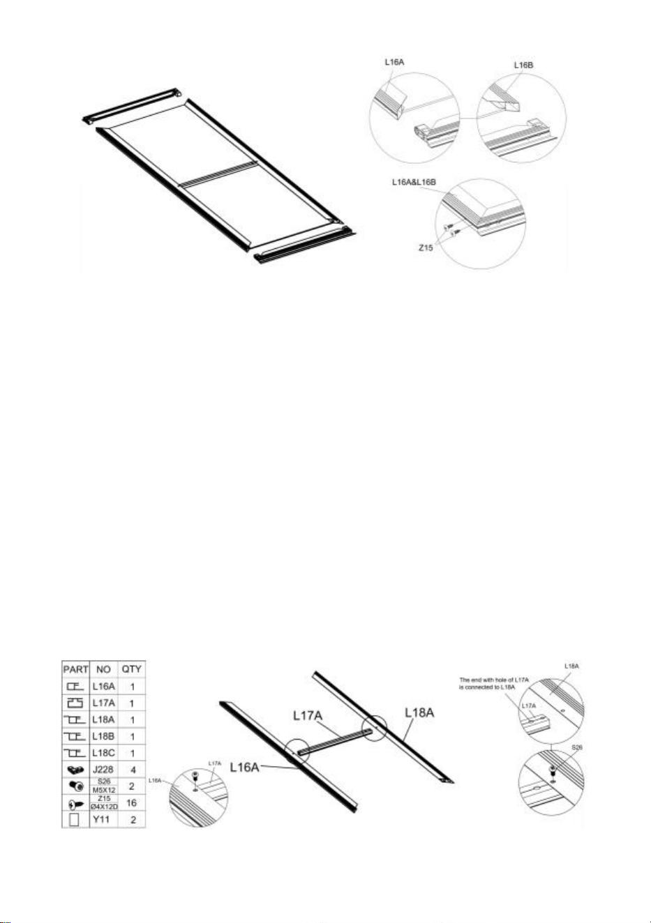
12
Zespół prawych drzwi
Krok 1:
Zmontuj części „L17 A ”, „L16A” i „L16 A ” z częścią „S26”, jak pokazano na rysunku.
Umieść część „Y11” w ramie.
Krok 2:
Umieść część „J228” w odpowiedniej pozycji części
„
L18 B ” i „L18 C ” zgodnie z
rysunkiem i użyj części „Z15”, aby to naprawić.
Krok 3:
Zamontuj element „L18” zmontowany w kroku 2 w ramie zgodnie z rysunkiem. Po
zmontowaniu elementu na miejscu, zabezpiecz go za pomocą części „Z15”.

13
Montaż okna
Krok 1:
Wsuń część „S28” do części „L21”, jak pokazano na rysunku. Następnie zmontuj razem
części „L20”, „L21” i „Y10”.
Krok 2:
Użyj części „Z15”, aby złożyć część „L19” z komponentami wykonanymi w poprzednim
kroku.
Krok 3:
Użyj części „Z15”, aby złożyć część „L11A” z komponentami wykonanymi w kroku 2.
Uwaga: w sumie są 2 okna.

14

15
Montaż szklarni
Krok 1:
Proszę zapoznać się z ilustracją, aby zapoznać się z lokalizacją części wymaganych do
montażu w tym kroku.
Narożnik: Zmontuj część „J217” i „L08”, używając części „Z15” .
Połączenie prętów aluminiowych: Po połączeniu dwóch prętów aluminiowych za pomocą
części „J222” , są one mocowane za pomocą części „Z15”.
Krok 2:

16
Jeśli planujesz przymocować szklarnię do stałego podłoża, możesz wykonać ten krok, aby
zwiększyć bezpieczeństwo szklarni.
Położenie montażowe złącza
„
D410” pokazano na poniższym rysunku.
Jeśli planujesz przymocować szklarnię do drewnianej podłogi, zapoznaj się z poniższym
rysunkiem, aby połączyć drewnianą podłogę ze szklarnią za pomocą części „D410” , „Z08” i
„Z26”.

17
Jeśli planujesz zainstalować go na solidnej podłodze , takiej jak beton. Najpierw określ
lokalizację otworu, który ma zostać wywiercony, użyj elektronarzędzia do wywiercenia
otworu o średnicy 8 mm, użyj młotka lub podobnego narzędzia, aby wbić część „J129” w
ziemię, a na koniec użyj części „D410”, „Z26” & „Z08” do połączenia podłogi ze szklarnią.
Krok 3:

18
Zmontuj część „ L01A ” , „ L01B ” , „ L01E ” i „ L01F ” z komponentami wykonanymi w kroku
1 , używając części „Z15” .
Krok 4 :
Po dwóch częściach „ L07B ” są połączone za pomocą części „J222” , są one mocowane za
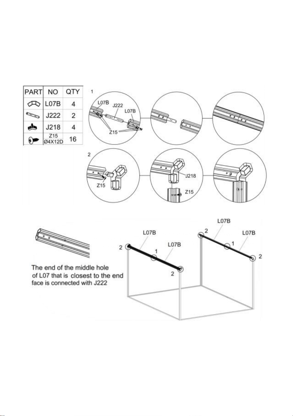
19
pomocą części
„
Z15
”
. Po połączeniu dwóch części
„
L07B
”
, należy je zamontować razem
z częścią „J218” zgodnie z końcem schematu i zabezpieczyć częścią „Z15”.
Po zamontowaniu elementu „L07” należy go zamontować na ramie wykonanej w
poprzednim kroku zgodnie z rysunkiem.
Krok 5 :
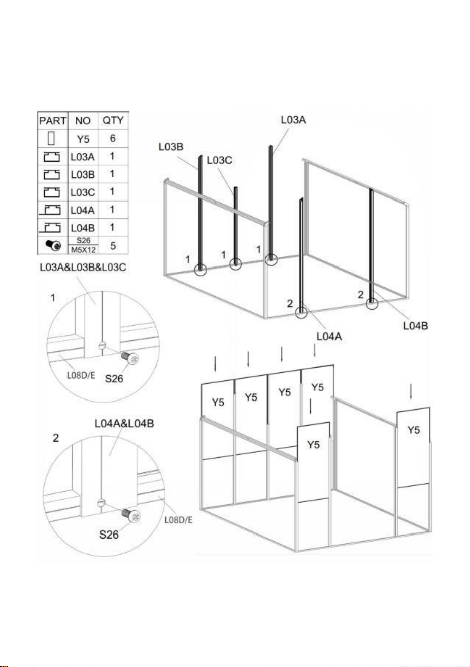
20
Używając części „ S26 ”, zainstaluj część art „ L03A ” , „ L03B ” , „ L03C ” , „ L04A ” i „ L04B ”
z komponentami ukończonymi w ostatnim kroku .
Włóż część „Y5” w odpowiednie miejsce, jak pokazano.
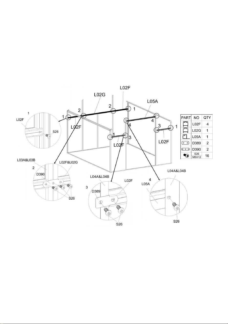
21
Krok 6 :
Używając części „ S26 ”, zainstaluj część art „ L02F ” , „ L02G ” i „ L05A ” z komponentami
ukończonymi w ostatnim kroku .
Szczegół Rysunek 1 : Użycie jednej części „ S26 ” do połączenia części „ L02F ” i ramy.
Szczegół Rysunek 2: Użycie części „ S26 ” i „ D390 ” do połączenia części „ L02F ” , „
L02G ” i ramy.
Szczegół Rysunek 3: Użycie części „ S26 ” i „ D389 ” do połączenia części „ L02F ” i ramy.
Szczegół Rysunek 4: Użycie jednej części „ S26 ” do połączenia części „ L05A ” i ramy.

22
Krok 7 :
Uwaga : Proszę dokładnie sprawdzić położenie części „L02A” i „L02J”, co będzie
miało wpływ na późniejszą instalację systemu Windows.
Użycie części „ S26 ” do połączenia części „ L02A ” lub „ L02J ” i ramy.
Użycie części „ S26 ” do połączenia części „ L03E ” i ramy.
Użycie części „ S26 ” i „ D390 ” do połączenia części „ L03D ” i ramy.
Uwaga : zainstaluj część „L02J” końcem z większą liczbą otworów skierowanym do
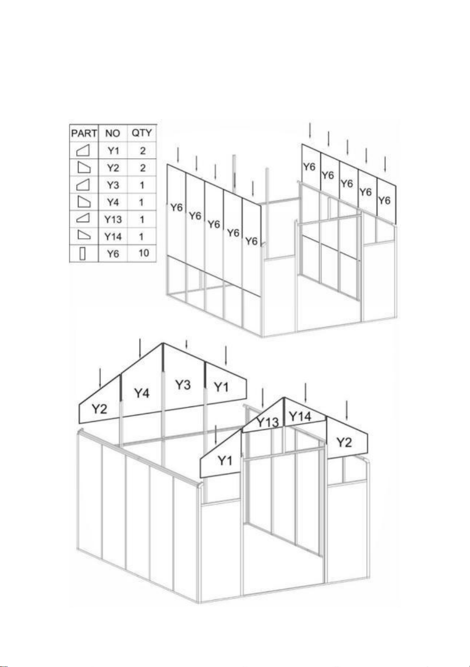
23
góry.
Krok 8 :
Włóż części „Y 1 ” , „Y 2 ” , „Y 3 ” , „Y 4 ” , „Y 13 ” , „Y 14 ” i „Y 6 ” w odpowiednie miejsce, jak
pokazano.

24
Krok 9 :
Części zamienne „ L01C ” i „ L01D ” są połączone za pomocą części „J22 0 ” , są one
mocowane za pomocą części „Z15”.
Zainstaluj komponent L01 na ramie, zgodnie z krokiem 8 zgodnie z rysunkiem i użyj części
„Z15” i „S26”, aby zablokować je po podłączeniu.
Zamontuj część „D406” na komponencie L01, używając części „S26”.
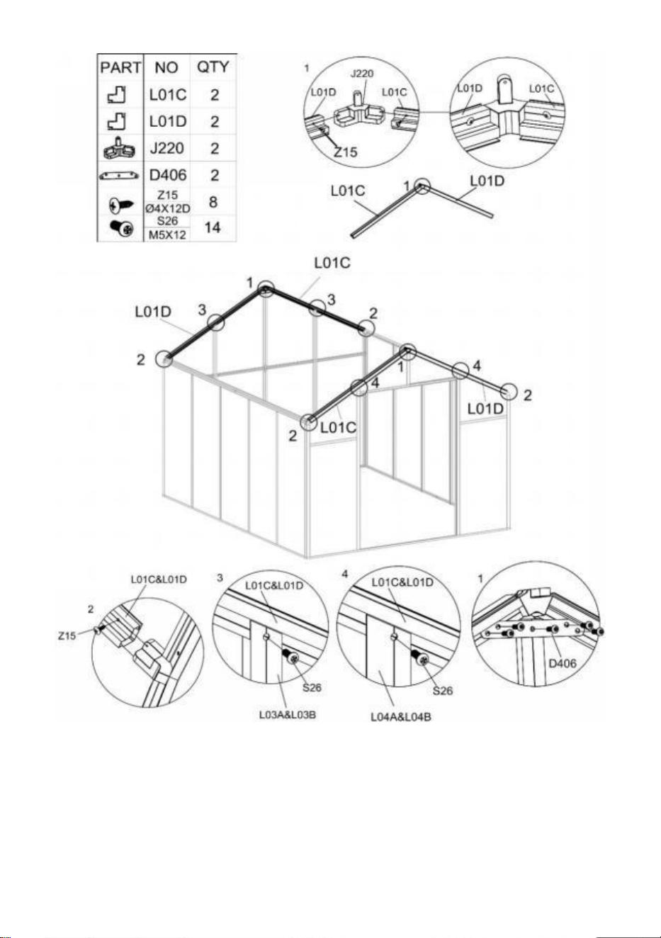
25
Krok 10 :
Po dwóch częściach „ L06B ” są połączone za pomocą części „J222” , są one mocowane za
pomocą części „Z15”.
Po zamontowaniu elementu „L0 6 ” należy go zamontować na ramie wykonanej w
poprzednim kroku zgodnie z rysunkiem i przymocowanej za pomocą części „Z15”.

26
Uwaga : Koniec środkowego otworu części „ L06 ” , który jest najbliżej powierzchni
czołowej, jest połączony z częścią „ J222 ” .
Krok 11 :
We wnętrzu szklarni umieść część „L02E” pomiędzy częściami „L06B” i „L07B” zgodnie z
rysunkiem i połącz je ze sobą za pomocą „S26”.
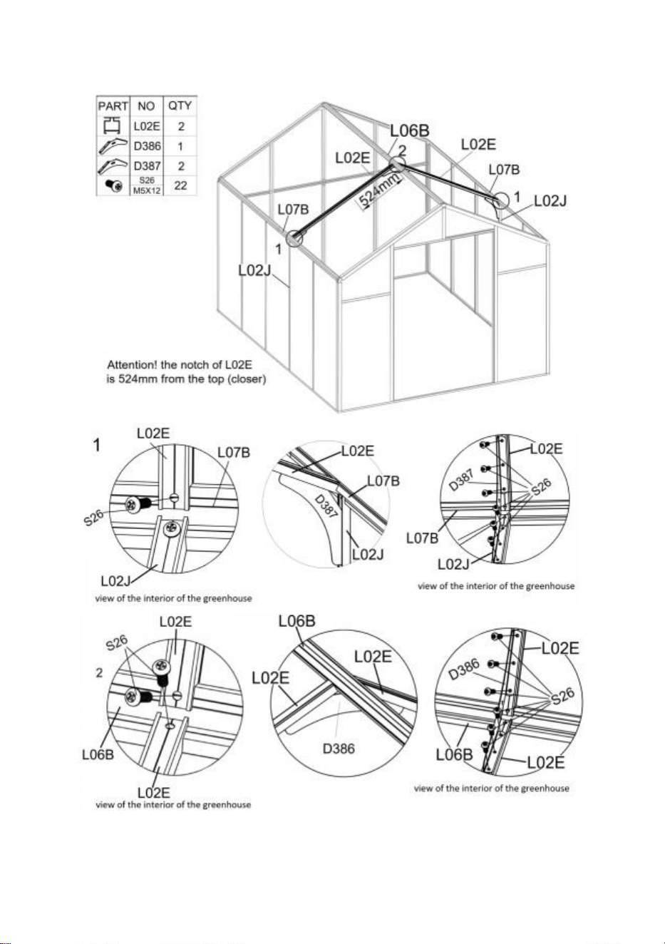
27
Połącz część „L02J” i „L02E” za pomocą „D387” z częścią „S26”.
Połącz dwie części „L02 E ” za pomocą „D38 6 ” z częścią „S26”.
Krok 1 2 :
We wnętrzu szklarni umieść część „L02 B ” lub „L02 C ” pomiędzy częściami „L06B” i
„L07B” zgodnie z rysunkiem i połącz je ze sobą za pomocą „S26”.

28
Uwaga
:
Części „L02B” i „L02C” należy zamontować zgodnie z pokazaną pozycją, w
przeciwnym razie będzie to miało wpływ na późniejszy montaż okna!
Po solidnym zamontowaniu części „L02B” i „L02C”, użyj „D26”, aby połączyć dwie części
„L06B” i użyj „Z08”, aby zabezpieczyć.
Krok 1 3 :
Zamontuj zespół okna „L11A” na ramie wykonanej w kroku 12 powyżej, używając części
„Z08”.
Użyj części „S26” i „D388”, aby zainstalować „L02H” na ramie.
Użyj części „M02” i „S26” i połącz okno z ościeżnicą za pomocą części „A111”.
Uwaga
:
Podczas montażu części „ A111 ” otwórz i zamknij okno, jednocześnie blokując
śruby i nakrętki. W przeciwnym razie po naprawie okno może nie przełączać się płynnie.

29

30
Krok 1 4 :
Włóż część „Y 7 ” i „Y 8 ” w odpowiednie miejsce, jak pokazano.
Użyj części „Z15” i „S26”, aby zainstalować „L09B” w pokazanej pozycji. Uwaga: śruby
użyte na rysunkach 1 i 2 będą się różnić.

31
Krok 1 5 :
Zamontuj „L09B” na ramie, używając części „Z15” i „S26”.
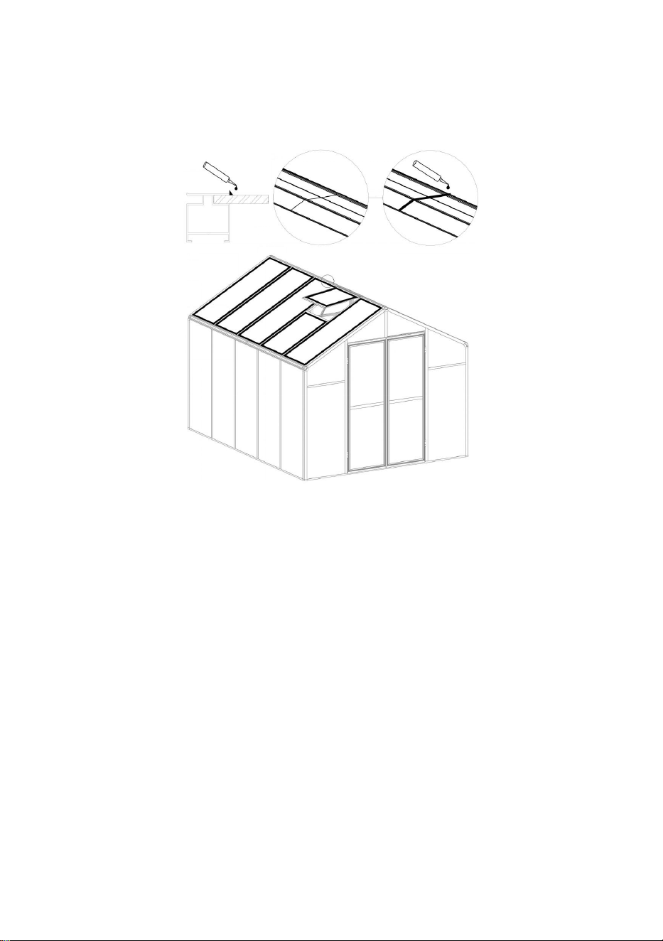
32
Krok 1 6 :
W zależności od potrzeb klienta na szczeliny pomiędzy aluminium a płytą w górnej części
produktu oraz na szczeliny pomiędzy aluminium nakłada się silikon w celu uzyskania
wodoodporności.
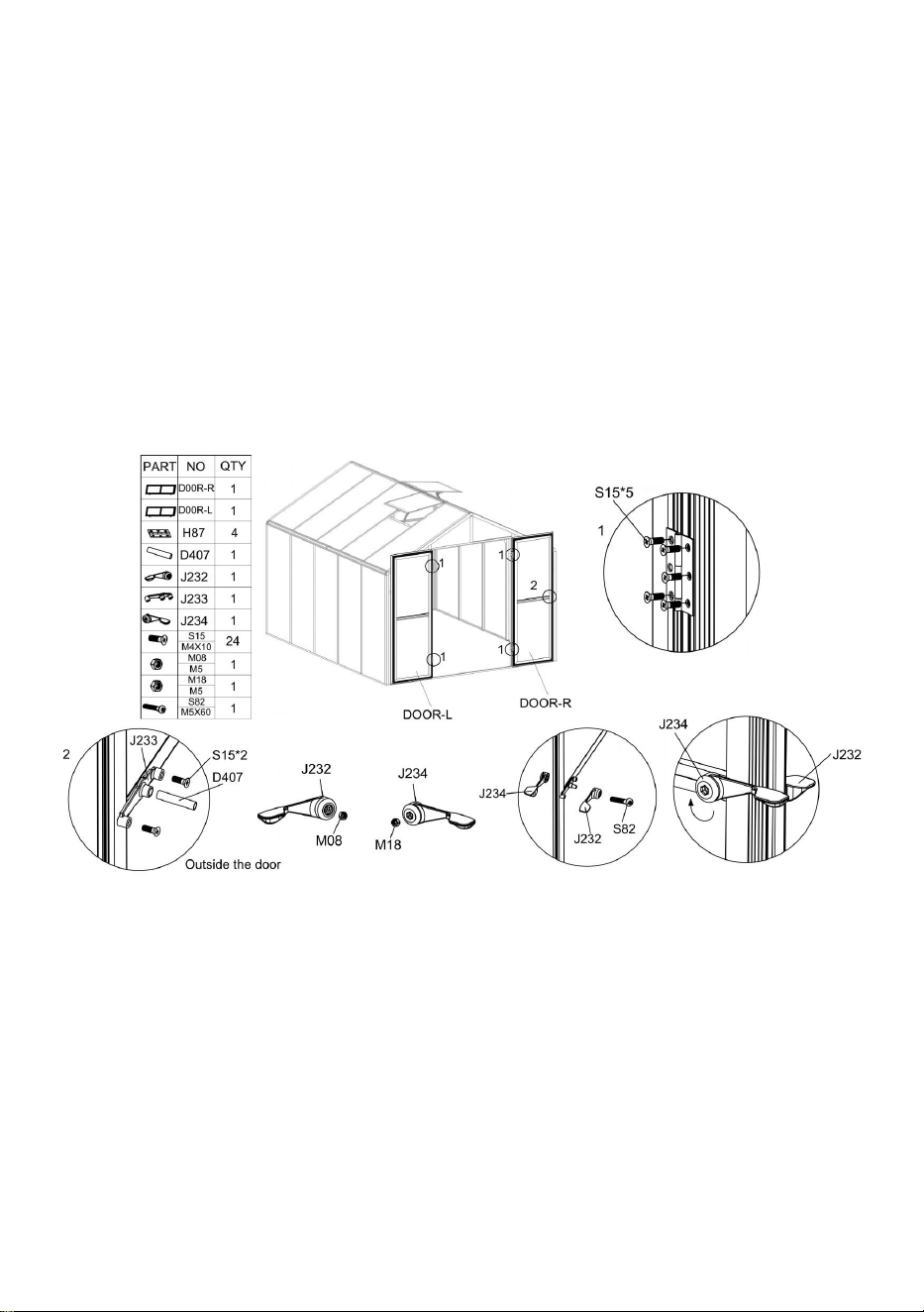
33
Krok 1 7 :
Zamontuj drzwi do ościeżnicy za pomocą części „ S 15” i „ H87 ”.
Notatka: Podczas instalowania drzwi należy przede wszystkim wyregulować położenie,
spróbować otworzyć i zamknąć drzwi podczas montażu, upewnić się, że drzwi otwierają się
i zamykają płynnie, a następnie zablokuj śruby.
Użyj części „S15”, aby zainstalować J233 na zewnętrznej stronie drzwi, jak pokazano , a
następnie włóż część „D407” do odpowiedniego otworu „J233”.
Umieść części „M08” i „M18” w odpowiednich otworach, odpowiednio, „J232” i „J234”.
Użyj części „S82”, aby zainstalować „J232” i „J234” po obu stronach drzwi, zgodnie z
rysunkiem. Jeśli części „J232” i „J234” nadal są luźne po podłączeniu, naciśnij „J232” i
obróć „J234” w prawo.
Obecnie zakończono montaż szklarni. Ciesz się tym !
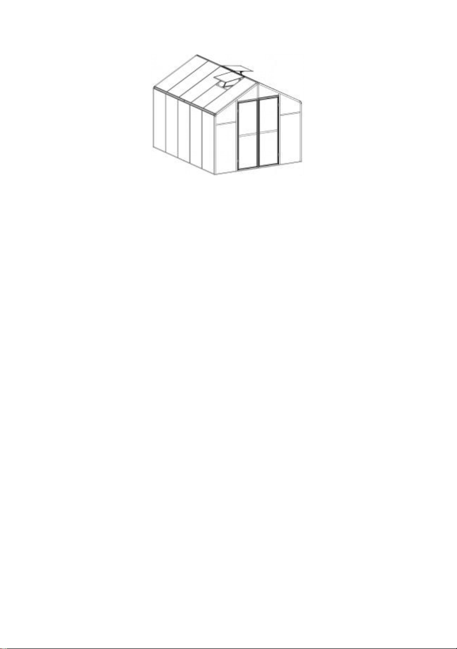
34

Producent: Shanghaimuxinmuyeyouxiangongsi
Adres: Shuangchenglu 803nong11hao1602A-1609shi, baoshanqu,
szanghaj 200000 CN.
Import do AUS: SIHAO PTY LTD. 1 ROKEVA STREETEASTWOOD NSW
2122 Australia
Import do USA: Sanven Technology Ltd. Suite 250, 9166 Anaheim
Place, Rancho Cucamonga, Kalifornia 91730


2
Technisch Ondersteuning en e-garantiecertificaat
www.vevor.com/support
POLYCARBONAAT BROEIKAS
GEBRUIKER HANDMATIG
We blijven ons inzetten om u gereedschap tegen een concurrerende prijs te bieden.
"Bespaar de helft", "Halve prijs" of andere soortgelijke uitdrukkingen die alleen door ons worden
gebruikt
vertegenwoordigt een schatting van de besparingen die u zou kunnen opleveren als u bepaalde
hulpmiddelen koopt
bij ons vergeleken met de grote topmerken en dat hoeft niet per se zo te zijn omslag
alle categorieën tools die door ons worden aangeboden. U wordt er vriendelijk aan herinnerd om dit te
verifiëren voorzichtig
wanneer u bij ons een bestelling plaatst, als u dat daadwerkelijk doet Besparing
Half in vergelijking met de belangrijkste grote merken.

3

1

1
Model: AM035
HULP NODIG? NEEM CONTACT MET ONS OP!
Heeft u productvragen? Technische ondersteuning nodig? Neem gerust contact
met ons op:
Technische ondersteuning en e-garantiecertificaat
www.vevor.com/support
Dit is de originele instructie. Lees alle instructies in de handleiding zorgvuldig door
voordat u ermee aan de slag gaat. VEVOR behoudt zich een duidelijke
interpretatie van onze gebruikershandleiding voor. Het uiterlijk van het product is
afhankelijk van het product dat u heeft ontvangen. Vergeef ons alstublieft dat we u
niet opnieuw informeren als er technologie- of software-updates zijn voor ons
product.
POLYCARBONATE
GREENHOUSE

2
INSTRUCTIES
Hartelijk dank voor het kiezen van dit product . Lees alle instructies voordat u het gebruikt.
De informatie zal u helpen de best mogelijke resultaten te bereiken.
LET OP! De tekeningen in deze handleiding zijn bedoeld voor alleen ter illustratie en in
sommige details mogelijk afwijken van het daadwerkelijke product.
AANDACHT! Lees alle veiligheidswaarschuwingen en alle instructies. Het niet opvolgen
van de waarschuwingen en instructies kan leiden tot ernstig letsel of zelfs de dood. Het
apparaat of product dat in de waarschuwingsinstructies wordt gebruikt, wordt verwezen
naar Polycarbonaatkas .
Dit product is geen speelgoed of speelgoedkist. Laat kinderen niet met dit artikel spelen.
Plaats het apparaat in een positie waarin kinderen niet kunnen klimmen om letsel door
vallen van een hoogte te voorkomen .
GEBRUIKSVEILIGHEID
1. Er zijn twee mensen nodig om dit product te monteren.
2. Sommige onderdelen hebben scherpe metalen randen. Wees voorzichtig bij het
hanteren van metaal componenten. Draag tijdens de werkzaamheden handschoenen,
schoenen en een veiligheidsbril montage.
3. Kies een plaats voor de montage die schoon is en vrij van vuil waardoor personen die
aan de montage werken kunnen struikelen.
4. Klim of sta niet op het dak. Zware voorwerpen mogen niet tegen de kas worden geleund.
5. Bekijk een voorbeeld van de montage-instructies in de gebruikershandleiding voordat u
verder gaat.
6. Nadat de montage is voltooid, inspecteert u de machine grondig om er zeker van te zijn
dat alle moeren, bouten, hydraulische fittingen of andere bevestigingsmiddelen goed zijn
vastgedraaid.
67. Dit product is geen speelvoorziening of tent en mag niet worden gebruikt voor andere
doeleinden dan polycarbonaatkassen.
8. De polycarbonaatkas moet vóór gebruik worden gecontroleerd om er zeker van te zijn
dat deze in goede staat verkeert en veilig functioneert. Anders , het apparaat mag niet
worden gebruikt.
9. We raden aan om het onderframe in een voorgegraven greppel te plaatsen nadat u de
plank met expansieschroeven (meegeleverd) aan de grond hebt bevestigd voor meer
stabiliteit en windweerstand in de temperatuurkamer .

3
10. Aanbevolen wordt om glaslijm aan te brengen op de verbinding tussen de printplaat en
het frame voor een betere bescherming tegen water .
11. Bij slecht weer adviseren wij om de kostbare spullen in de kas te verwijderen om
onnodig verlies van eigendommen te voorkomen en de kas gedurende die tijd niet te
gebruiken .
12. Houd het dak sneeuw- en bladvrij. Als er zich sneeuw op het dak ophoopt, kan het
product beschadigd raken.
Voordat u het product gebruikt: als u vragen heeft over de juiste montage of bediening,
neem dan contact op met uw dealer of vertegenwoordiger.
19. Als uw product moet worden gereinigd, gebruik dan een mild schoonmaakmiddel en
spoel af met koud, schoon water. Gebruik geen aceton, schurende schoonmaakmiddelen of
sterke schoonmaakmiddelen om de panelen schoon te maken.
BEWAAR DEZE INSTRUCTIES
TECHNISCHE PARAMETERS
Model
AM035
Kleur
Zwart aluminium
Materiaal
Aluminium , polycarbonaatplaat
Productgrootte
236*289*206cm

4
Onderdelenlijst

5
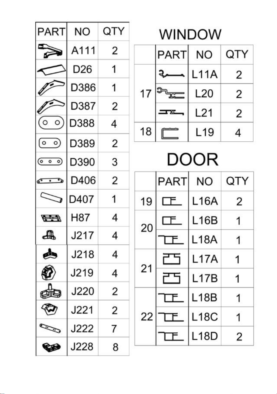
6

7
Lijst met pc-kaarten
Als het aluminium onderdeel gebogen is zoals op onderstaande foto, gebruik dan de sleutel

8
om het te herstellen.
Verwijder ongeveer 5 cm folie van alle plaatranden voordat u het installeert en verwijder alle
folie onmiddellijk nadat de constructie is voltooid. Zorg ervoor dat de kant met de witte folie
naar buiten wijst.
Let op : De meeste onderdelen "S26" zijn op het aluminium geïnstalleerd en moeten vóór
installatie worden verwijderd volgens de instructies.

9
Distributie van printplaten

10
Montage linkerdeur

11
Stap 1:
Monteer de onderdelen "L17B", "L16A" en "L16B" met onderdeel "S26" zoals weergegeven
in de afbeelding. Plaats onderdeel "Y11" in het frame.
Stap 2:
Plaats onderdeel “J228” in de overeenkomstige positie van onderdeel “L18D” volgens de
afbeelding, en gebruik onderdeel “Z15” om het te repareren.
Stap 3:
Installeer het onderdeel "L18", gemonteerd in stap 2, in het frame volgens de afbeelding.
Nadat het onderdeel op zijn plaats is gemonteerd, zet u het vast met onderdeel "Z15".

12
Montage rechterdeur
Stap 1:
Monteer de onderdelen "L17 A ", "L16A" en "L16 A " met onderdeel "S26" zoals
weergegeven in de afbeelding. Plaats onderdeel "Y11" in het frame.
Stap 2:
Plaats onderdeel "J228" in de overeenkomstige positie van onderdeel "L18 B " & "L18 C "
volgens de afbeelding en gebruik onderdeel "Z15" om het te repareren.
Stap 3:
Installeer het onderdeel "L18", gemonteerd in stap 2, in het frame volgens de afbeelding.
Nadat het onderdeel op zijn plaats is gemonteerd, zet u het vast met onderdeel "Z15".

13
Raammontage
Stap 1:
Schuif onderdeel "S28" in onderdeel "L21" zoals weergegeven in de afbeelding. Monteer
vervolgens onderdeel "L20", "L21" en "Y10" samen.
Stap 2:
Gebruik onderdeel "Z15" om onderdeel "L19" samen te stellen met de componenten die in
de vorige stap zijn voltooid.
Stap 3:
Gebruik onderdeel "Z15" om onderdeel "L11A" te monteren met de componenten voltooid
in stap 2.
Let op: Er zijn in totaal 2 vensters.

14
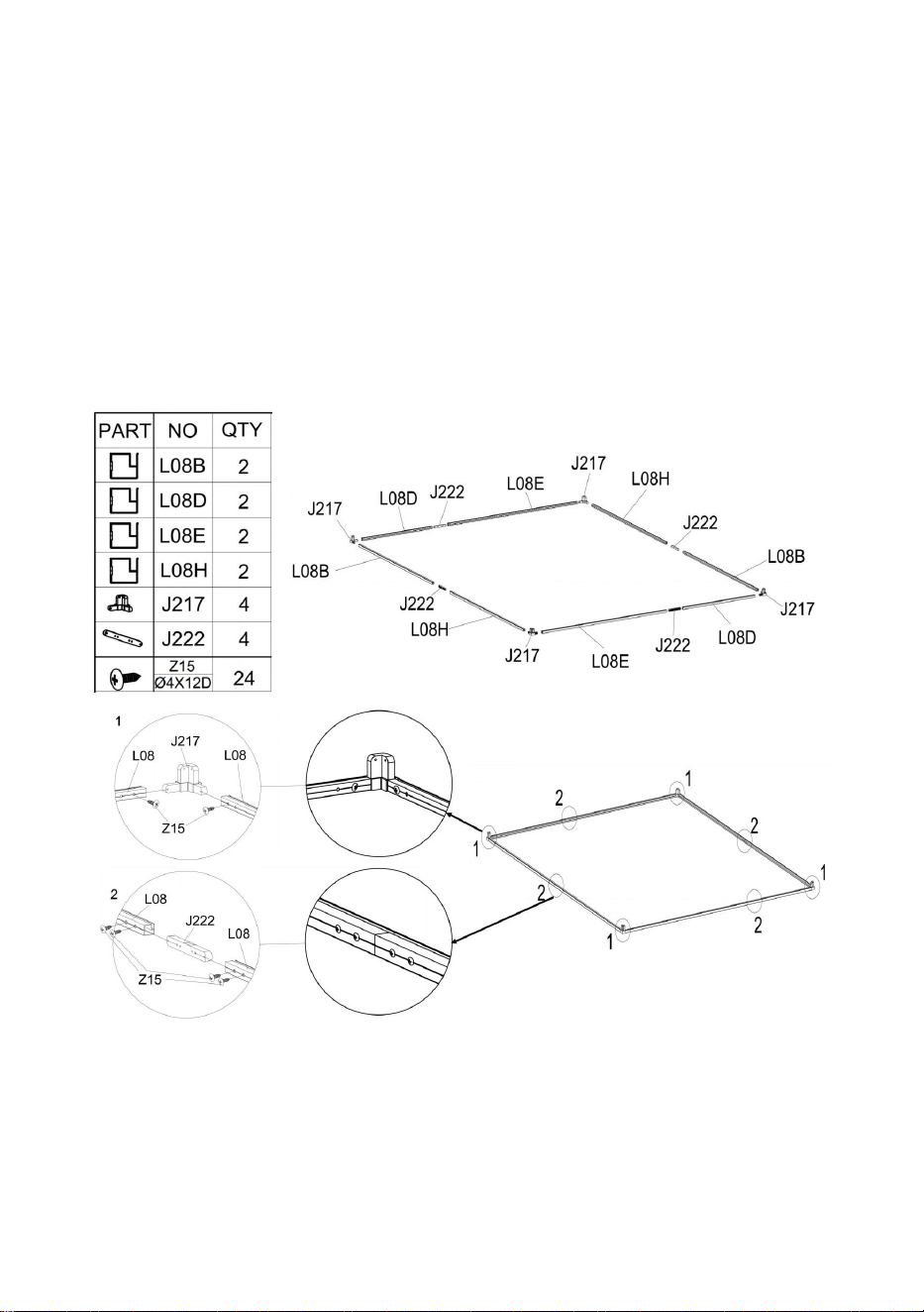
15
Kasvergadering
Stap 1:
Raadpleeg de afbeelding voor de locatie van de onderdelen die nodig zijn voor installatie in
deze stap.
Hoek: Monteer onderdeel "J217" en "L08" met behulp van onderdeel "Z15" .
Aluminium staafverbinding: Nadat de twee aluminium staven zijn verbonden met behulp
van onderdeel "J222" , ze zijn opgelost met onderdeel "Z15".
Stap 2:

16
Als u van plan bent uw kas op vaste grond te bevestigen, kunt u deze stap volgen om uw
kas veiliger te maken.
De inbouwpositie van connectoronderdeel " D410" wordt weergegeven in de volgende
afbeelding.
Als u van plan bent de kas aan de houten vloer te bevestigen, raadpleeg dan de
onderstaande afbeelding om de houten vloer aan de kas te bevestigen met behulp van
onderdeel "D410" , "Z08" en "Z26".

17
vloer , zoals beton, te installeren . Bepaal eerst de locatie van het te boren gat, gebruik het
elektrisch gereedschap om het gat met een diameter van 8 mm te boren, gebruik een
hamer of soortgelijk gereedschap om onderdeel "J129" in de grond te slaan en gebruik ten
slotte onderdeel "D410", "Z26" & "Z08" om de vloer met de kas te verbinden.
Stap 3:
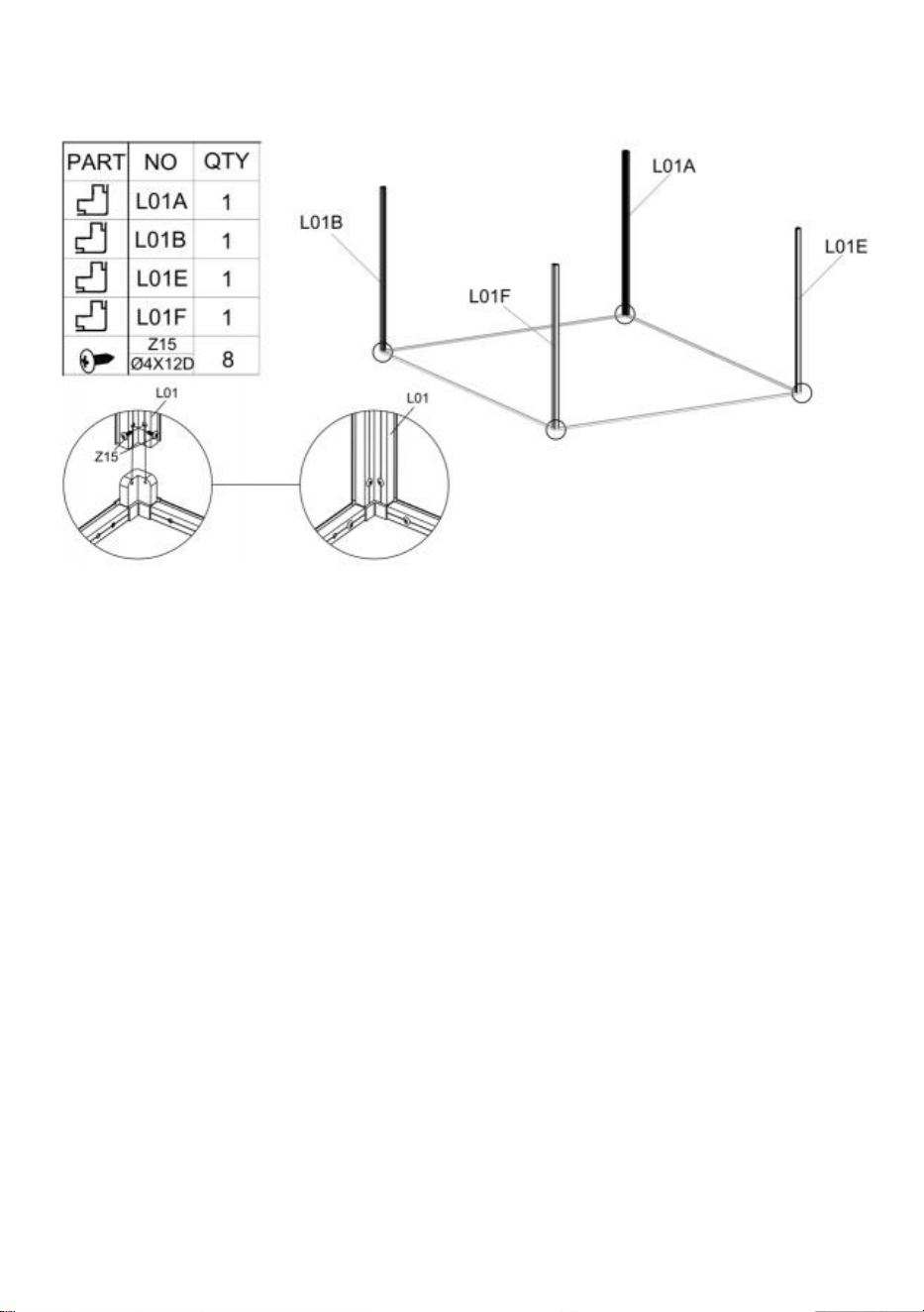
18
Monteer onderdeel " L01A " , " L01B " , " L01E " en " L01F " met de componenten voltooid in
stap 1 met behulp van onderdeel "Z15" .
Stap 4 :
Na de twee delen " L07B " zijn aangesloten via onderdeel "J222" worden ze vastgezet met

19
onderdeel "Z15". Nadat twee onderdelen "L07B" zijn aangesloten, installeert u ze samen
met onderdeel "J218" volgens het einde van het diagram, en zet u ze vast met onderdeel
"Z15".
Na de installatie van het onderdeel "L07" installeert u het op het frame dat u in de vorige
stap hebt voltooid, volgens de afbeelding.
Stap 5 :

20
Gebruik onderdeel " S26 ", installeer onderdeel art " L03A " , " L03B " , " L03C " , " L04A " en
" L04B " met de componenten die in de laatste stap zijn voltooid .
Plaats onderdeel "Y5" in de overeenkomstige positie, zoals weergegeven.
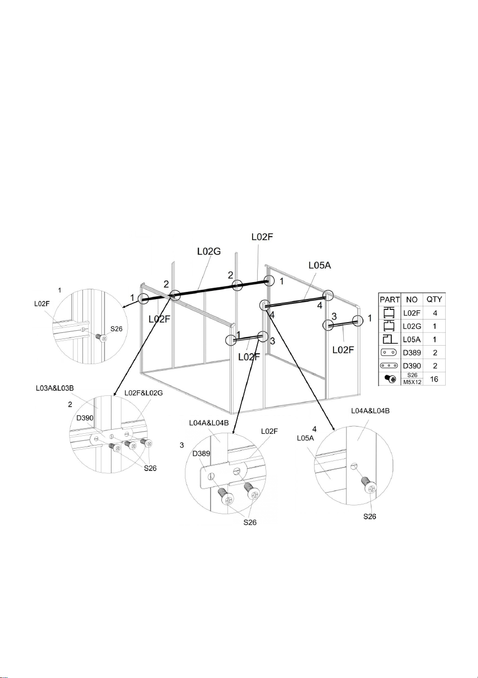
21
Stap 6 :
Gebruik onderdeel " S26 ", installeer onderdeel art " L02F " , " L02G " en " L05A " met de
componenten die in de laatste stap zijn voltooid .
Detail Figuur 1 : Eén onderdeel " S26 " gebruiken om onderdeel " L02F " en frame aan te
sluiten.
Detail Afbeelding 2: Gebruik onderdeel " S26 " en " D390 " om onderdeel " L02F " , " L02G "
en frame aan te sluiten.
Detail Afbeelding 3: Gebruik onderdeel " S26 " en " D389 " om onderdeel " L02F " en frame
aan te sluiten.
Detail Afbeelding 4: Eén onderdeel " S26 " gebruiken om onderdeel " L05A " en frame aan
te sluiten.
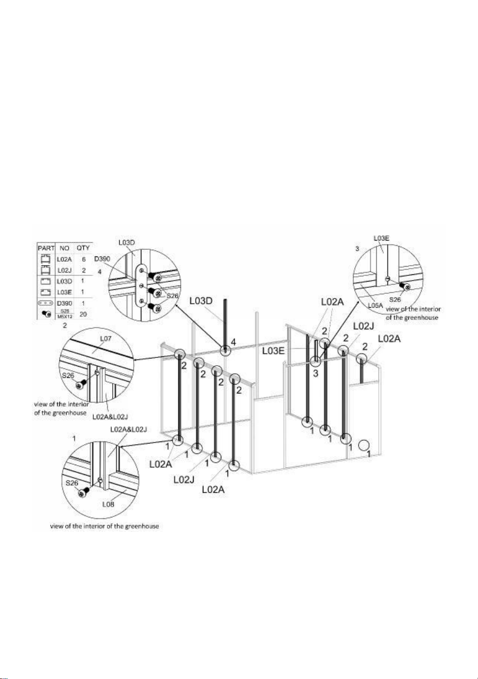
22
Stap 7 :
Let op: Controleer zorgvuldig de positie van de onderdelen "L02A" en "L02J", die de
daaropvolgende installatie van Windows zullen beïnvloeden.
Gebruik onderdeel " S26 " om onderdeel " L02A " of " L02J " en frame aan te sluiten.
Gebruik onderdeel " S26 " om onderdeel " L03E " en frame te verbinden.
Gebruik onderdeel " S26 " & " D390 " om onderdeel " L03D " en frame te verbinden.
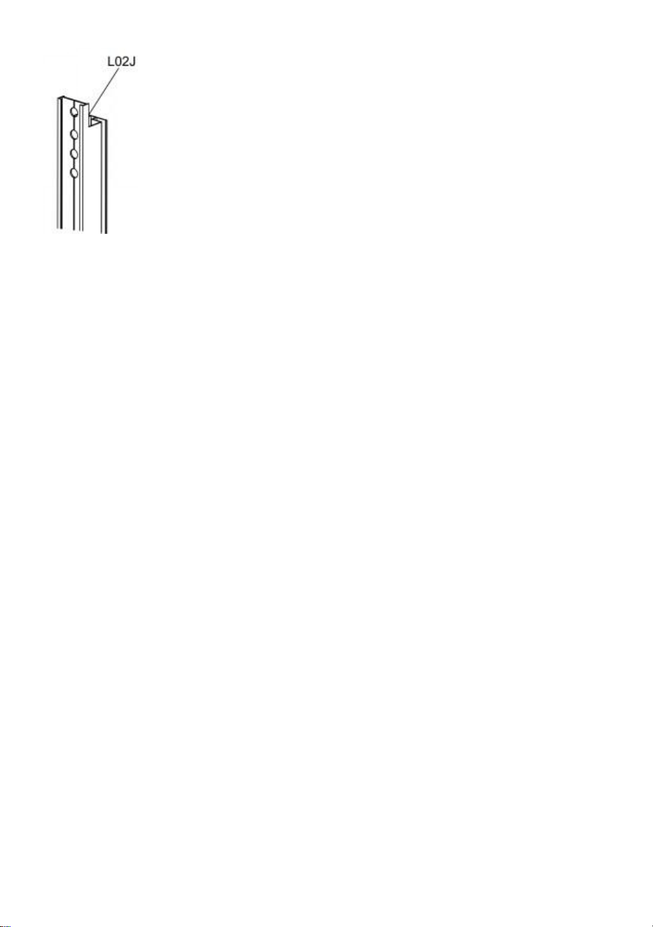
23
Let op: installeer onderdeel “L02J” met het uiteinde met de meer gaten naar boven
gericht.
Stap 8 :
Plaats onderdeel "Y 1 " , "Y 2 " , "Y 3 " , "Y 4 " , "Y 13 " , "Y 14 " en "Y 6 " in de
overeenkomstige positie, zoals weergegeven.

24
Stap 9 :
Na deel s " L01C " & " L01D " zijn aangesloten via onderdeel "J22 0 " , ze zijn opgelost met
onderdeel "Z15".
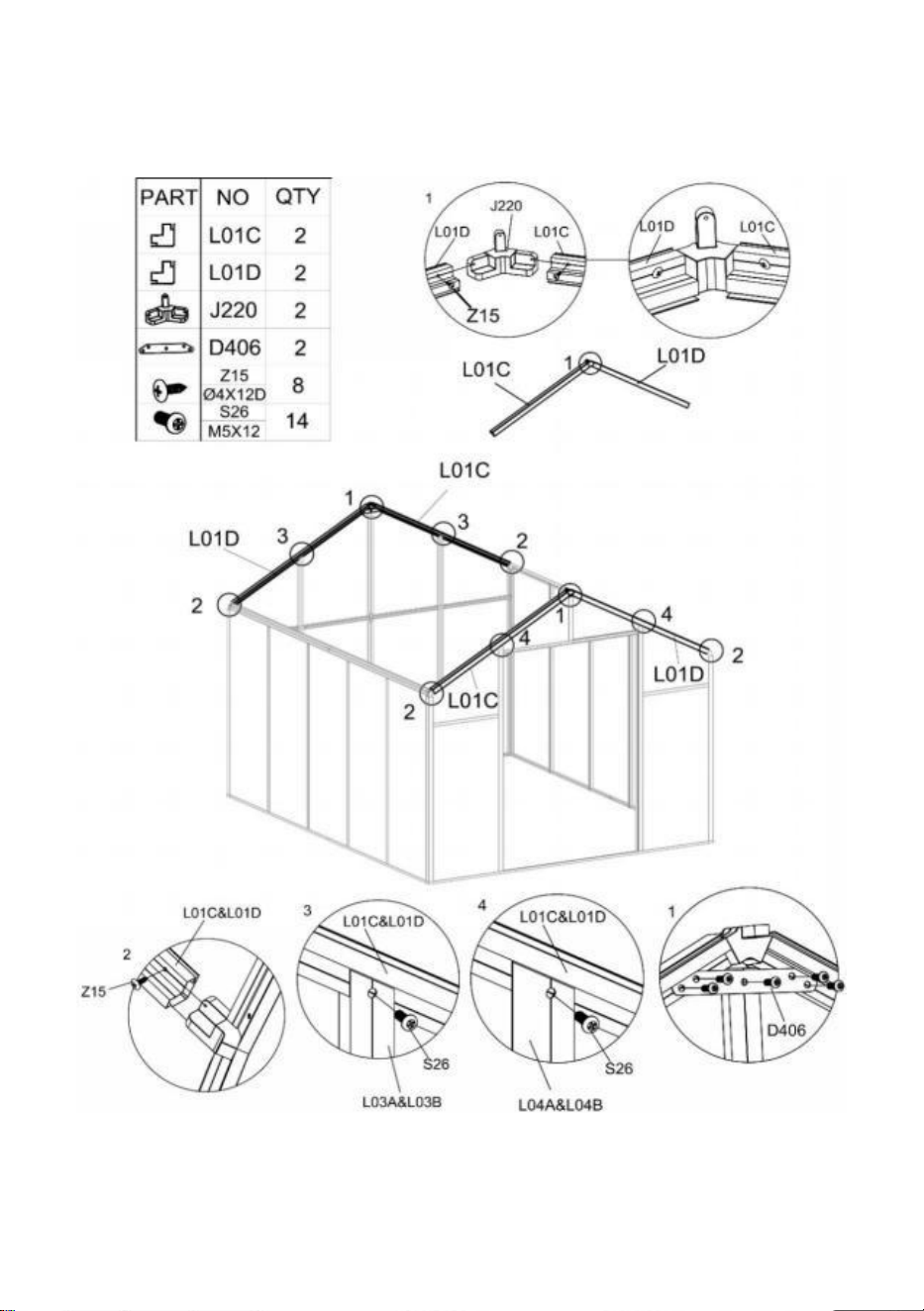
25
Installeer het L01-onderdeel op het frame dat u in stap hebt voltooid 8 volgens de
afbeelding, en gebruik onderdeel "Z15" en "S26" om het na aansluiting te vergrendelen.
Installeer onderdeel "D406" op de component van L01 met behulp van onderdeel "S26".
Stap 10 :
Na de twee delen " L06B " zijn aangesloten via onderdeel "J222" , ze zijn opgelost met
onderdeel "Z15".

26
Na de installatie van het onderdeel "L0 6 ", installeert u het op het frame dat u in de vorige
stap hebt voltooid, volgens de afbeelding en vastgezet met onderdeel "Z15".
Let op: Het uiteinde van het middelste gat van onderdeel “ L06 ” dat het dichtst bij het
eindvlak ligt, is verbonden met onderdeel “ J222 ” .
Stap 11 :
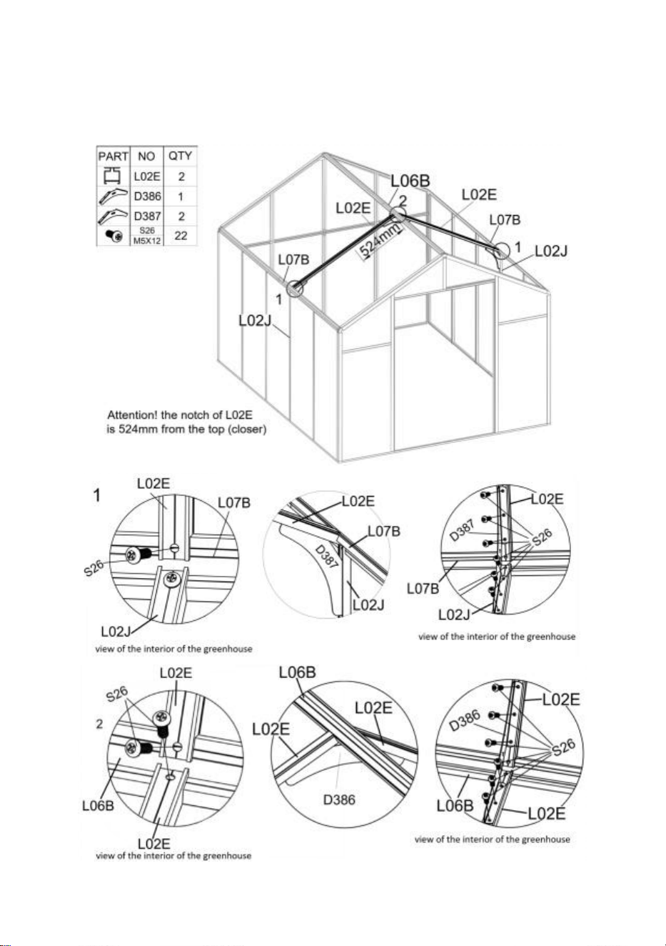
27
Plaats binnenin de kas onderdeel "L02E" tussen de onderdelen "L06B" en "L07B" volgens
de tekening en bevestig ze aan elkaar met "S26".
Verbind onderdeel "L02J" en "L02E" met behulp van "D387" met onderdeel "S26".
Verbind twee onderdelen "L02 E " met behulp van "D38 6 " met onderdeel "S26".
Stap 1 2 :

28
Plaats binnen in de kas onderdeel "L02 B " of "L02 C " tussen de onderdelen "L06B" en
"L07B" volgens de tekening en zet ze samen vast met "S26".
Aandacht
:
Onderdeel "L02B" en "L02C" moeten worden geïnstalleerd in overeenstemming
met de weergegeven positie, anders heeft dit invloed op de daaropvolgende raammontage!
Nadat de onderdelen "L02B" en "L02C" stevig zijn geïnstalleerd, gebruikt u "D26" om de
twee "L06B" te verbinden en gebruikt u "Z08" om ze vast te zetten.
Stap 1 3 :
Installeer de raamconstructie "L11A" op het frame dat u in stap 12 hierboven hebt voltooid,
met behulp van onderdeel "Z08".
Gebruik onderdelen "S26" en "D388" om "L02H" op het frame te installeren.
Gebruik onderdeel "M02" en "S26" en verbind het raam met het frame met onderdeel
"A111".
Let op
:
Bij het installeren van onderdeel " A111 " , open en sluit u het raam en vergrendelt u
tegelijkertijd de schroeven en moeren. Anders schakelt het raam mogelijk niet soepel nadat
het is gerepareerd.
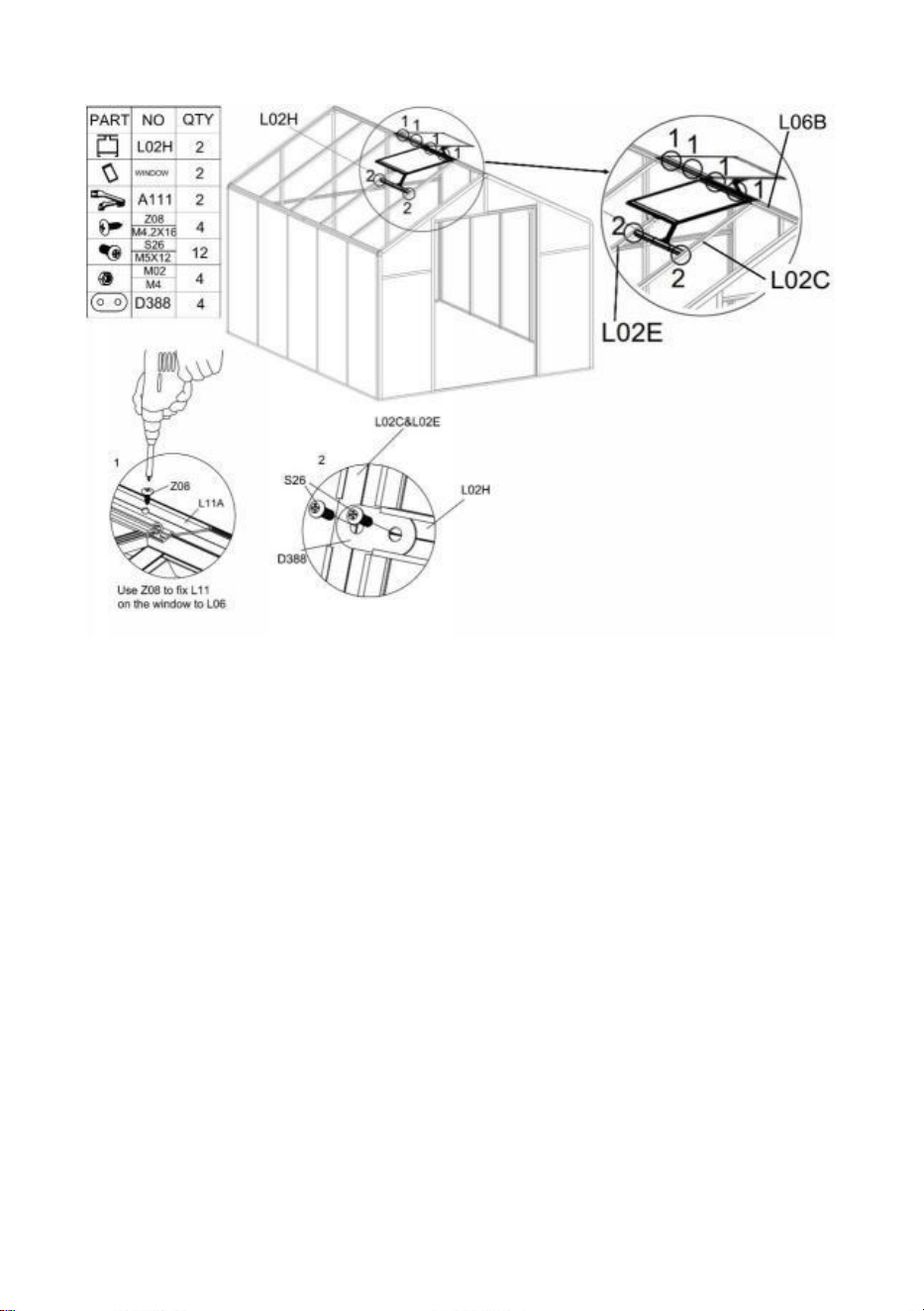
29
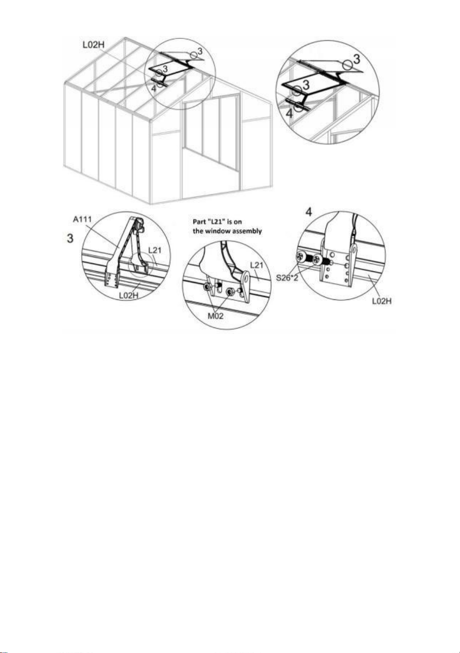
30
Stap 1 4 :
Plaats onderdeel "Y 7 " en "Y 8 " in de overeenkomstige positie, zoals weergegeven.
Gebruik onderdelen "Z15" en "S26" om "L09B" in de weergegeven positie te installeren.
Opmerking: De schroeven die in Figuur 1 en 2 worden gebruikt, zullen verschillend zijn.
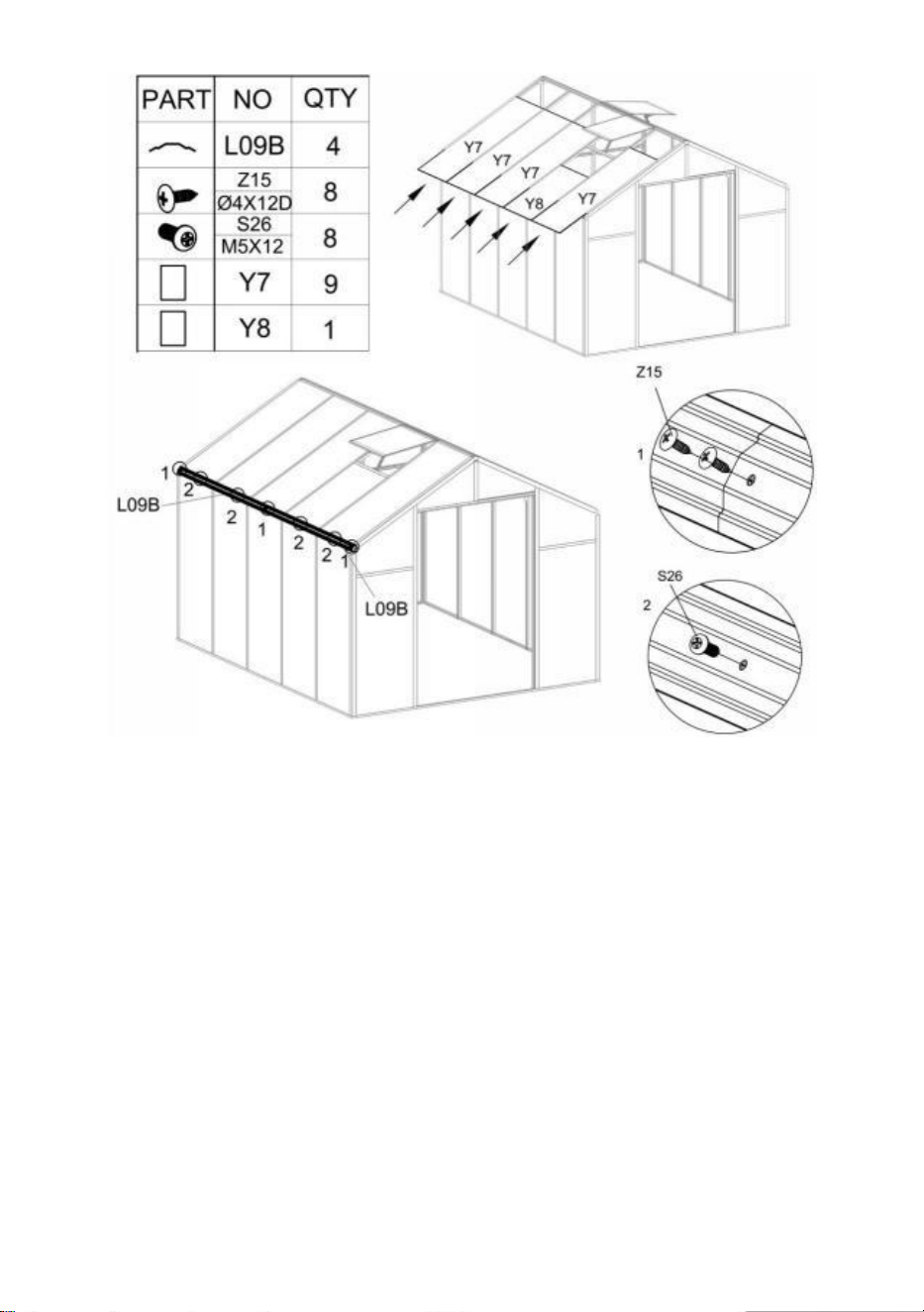
31
Stap 1 5 :
Installeer "L09B" op het frame met behulp van de onderdelen "Z15" en "S26".
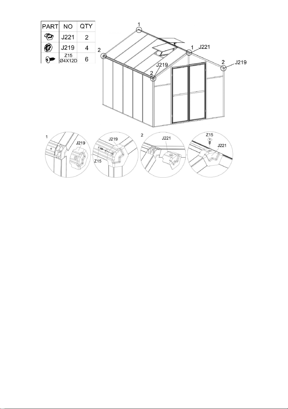
32
Stap 1 6 :
Afhankelijk van de behoeften van de klant wordt siliconen aangebracht op de openingen
tussen het aluminium en de plaat aan de bovenkant van het product, en op de openingen

33
tussen het aluminium om waterdichtheid te bereiken.
Stap 1 7 :
Installeer de deur op het frame met behulp van de onderdelen " S 15" en " H87 ".
Opmerking: Pas bij het installeren van de deur vooral de positie aan, probeer de deur
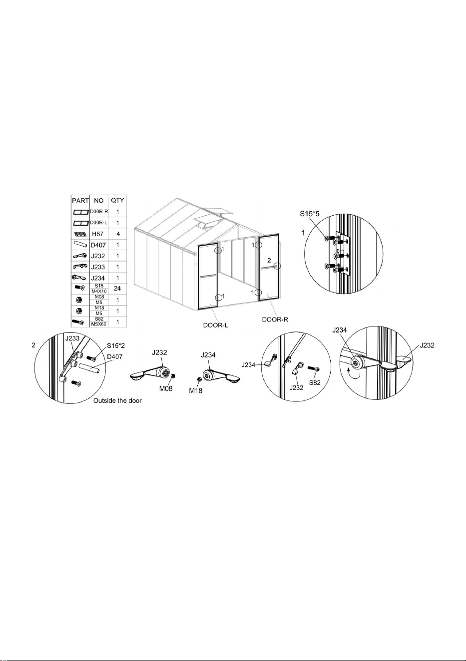
34
tijdens de installatie te openen en te sluiten, zorg ervoor dat de deur soepel opent en sluit
en vergrendel vervolgens de schroeven.
Gebruik onderdeel "S15" om J233 aan de buitenkant van de deur te installeren, zoals
afgebeeld , en plaats vervolgens onderdeel "D407" in het overeenkomstige gat van "J233".
Plaats het onderdeel "M08" en "M18" in de overeenkomstige gaten van respectievelijk
"J232" en "J234".
Gebruik onderdeel "S82" om "J232" en "J234" aan beide zijden van de deur te installeren,
zoals weergegeven in de afbeelding. Als onderdeel "J232" en "J234" nog steeds los zitten
nadat ze zijn aangesloten, drukt u op "J232" en draait u "J234" met de klok mee.
Nu is de installatie van de kas voltooid. Geniet ervan !

35

Fabrikant: Shanghaimuxinmuyeyouxiangongsi
Adres: Shuangchenglu 803nong11hao1602A-1609shi, baoshanqu,
shanghai 200000 CN.
Geïmporteerd naar AUS: SIHAO PTY LTD. 1 ROKEVA
STREETEASTWOOD NSW 2122 Australië
Geïmporteerd in de VS: Sanven Technology Ltd. Suite 250, 9166
Anaheim
Plaats, Rancho Cucamonga, CA 91730


2
Teknisk Support och e-garanticertifikat
www.vevor.com/support
POLYKARBONAT VÄXTHUS
ANVÄNDARE MANUELL
Vi fortsätter att vara engagerade i att ge dig verktyg till konkurrenskraftiga priser.
"Spara hälften", "Halva priset" eller andra liknande uttryck som endast används av oss
representerar en uppskattning av besparingar du kan dra nytta av att köpa vissa verktyg
med oss jämfört med de stora toppmärkena och betyder inte nödvändigtvis att täcka
alla kategorier av verktyg som erbjuds av oss. Du påminns vänligen om att verifiera försiktigt
när du gör en beställning hos oss om du faktiskt gör det Sparande
Halv i jämförelse med de främsta varumärkena.

1

1
Modell: AM035
BEHÖVER HJÄLP? KONTAKTA OSS!
Har du produktfrågor? Behöver du teknisk support? Kontakta oss gärna:
Teknisk support och e-garanticertifikat
www.vevor.com/support
Detta är den ursprungliga instruktionen, läs alla instruktioner noggrant innan du
använder den. VEVOR reserverar sig för en tydlig tolkning av vår användarmanual.
Utseendet på produkten är beroende av den produkt du fått. Ursäkta oss att vi inte
kommer att informera dig igen om det finns någon teknik eller
mjukvaruuppdateringar på vår produkt.
INSTRUKTIONER
POLYCARBONATE
GREENHOUSE

2
Tack så mycket för att du valde denna produkt . Läs alla instruktioner innan du använder
den. Informationen hjälper dig att uppnå bästa möjliga resultat.
OBS! Ritningar i denna handbok är till för endast i illustrationssyfte och i vissa detaljer kan
skiljer sig från den faktiska produkten.
UPPMÄRKSAMHET! Läs alla säkerhetsvarningar och alla instruktioner. Underlåtenhet att
följa varningarna och instruktionerna kan leda till allvarliga skador eller till och med dödsfall.
Enheten eller produkten som används i varningsinstruktionerna hänvisas till
polykarbonatväxthus .
Denna produkt är inte en leksak eller en leksakskrin. Tillåt inte barn att leka med detta
föremål. Vänligen placera i en position så att barn inte kan klättra för att undvika skador från
fall från höjd .
ANVÄNDNINGSSÄKERHET
1. Två personer krävs för att montera denna produkt.
2. Vissa komponenter har vassa metallkanter. Var försiktig när du hanterar metall
komponenter. Vänligen använd handskar, skor och skyddsglasögon under montering.
3. Välj ett område för montering som är rent och fritt från skräp som kan få personer som
arbetar på enheten att snubbla.
4. Klättra eller stå inte på taket. Tunga föremål ska inte lutas mot växthuset.
5. Förhandsgranska monteringsinstruktionerna i din bruksanvisning innan du fortsätter.
6. Efter avslutad montering, inspektera maskinen noggrant för att vara säker på att alla
muttrar, bultar, hydrauliska kopplingar eller andra fästanordningar har dragits åt ordentligt.
67. Denna produkt är inte en lekanläggning eller tält och bör inte användas för andra
ändamål än polykarbonatväxthus.
8. Växthuset av polykarbonat måste kontrolleras för att säkerställa att det är i gott skick och
fungerar säkert före användning. Annat , apparaten får inte användas.
9. Vi rekommenderar att du placerar bottenramen i ett förgrävt dike efter att du har fäst
brädan med expansionsskruvar (ingår) i marken för större stabilitet och
temperaturkammarens vindmotstånd .
10. Rekommendera att applicera glaslim på anslutningen mellan kretskort och ram för
bättre vattenskydd .
11. När vädret är dåligt rekommenderar vi att de dyrbara föremålen i växthuset tas bort för
att undvika onödig förlust av egendom och att inte använda växthuset under den tiden .
12. Håll taket rent från snö och löv. Att låta snö byggas upp på taket kan skada produkten.
Innan du använder produkten - om du har några frågor angående korrekt montering eller

3
användning, kontakta din återförsäljare eller representant.
20. När din produkt behöver rengöras, använd ett milt rengöringsmedel och skölj med kallt
rent vatten. Använd inte aceton, slipande rengöringsmedel eller starka rengöringsmedel för
att rengöra panelerna.
SPARA DESSA INSTRUKTIONER
TEKNISKA PARAMETRAR
Modell
AM035
Färg
Svart aluminium
Material
Aluminium , polykarbonatskiva
Produktstorlek
236*289*206 cm
Dellista

4

5

6
PC Board List
Om aluminiumdelen är böjd som på bilden nedan, använd skiftnyckeln för att återställa den.
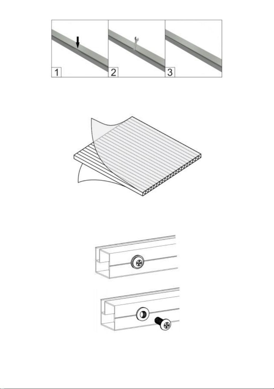
7
Ta bort cirka 2 tum film från alla arkkanter innan du installerar och ta bort all film omedelbart
efter att konstruktionen är klar. Se till att sidan med den vita filmen är vänd utåt.
Observera : De flesta av delarna "S26" är installerade på aluminiumet och måste tas bort
innan installation enligt instruktionerna.
PC-kort distribution

8
Vänster dörrmontering

9
Steg 1:
Montera delarna "L17B", "L16A" och "L16B" med delen "S26" enligt bilden. Placera del
"Y11" i ramen.
Steg 2:
Placera del “J228” i motsvarande position för del “L18D” enligt bilden och använd del “Z15”
för att fixa den.
Steg 3:
Installera "L18"-komponenten som monterades i steg 2 i ramen enligt bilden. Efter att
komponenten har monterats på plats, säkra den med del "Z15".

10
Höger dörrmontering
Steg 1:
Montera delarna "L17 A ", "L16A" och "L16 A " med delen "S26" enligt bilden. Placera del
"Y11" i ramen.
Steg 2:
Placera del "J228" i motsvarande position för del "L18 B " & "L18 C " enligt bilden och
använd P art "Z15" för att fixa det.
Steg 3:
Installera "L18"-komponenten som monterades i steg 2 i ramen enligt bilden. Efter att
komponenten har monterats på plats, säkra den med del "Z15".
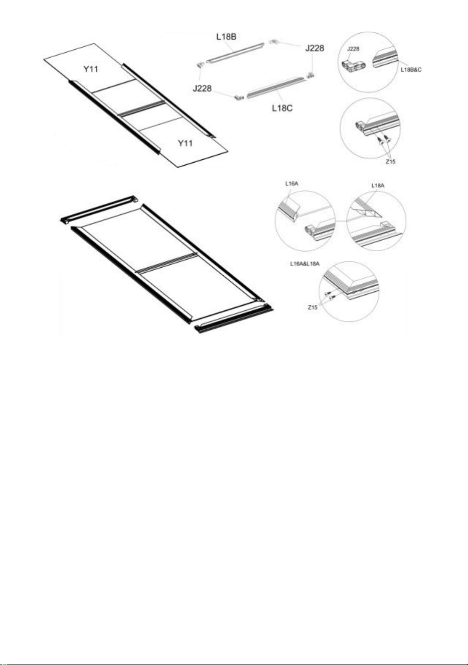
11
Fönstermontering
Steg 1:
Skjut in del "S28" i del "L21" som visas i figuren. Montera sedan del "L20", "L21" och "Y10"
tillsammans.
Steg 2:
Använd del "Z15" för att montera del "L19" med de komponenter som gjorts i föregående
steg.
Steg 3:
Använd del "Z15" för att montera del "L11A" med komponenterna som gjordes i steg 2.
Observera: Det finns 2 fönster totalt.

12
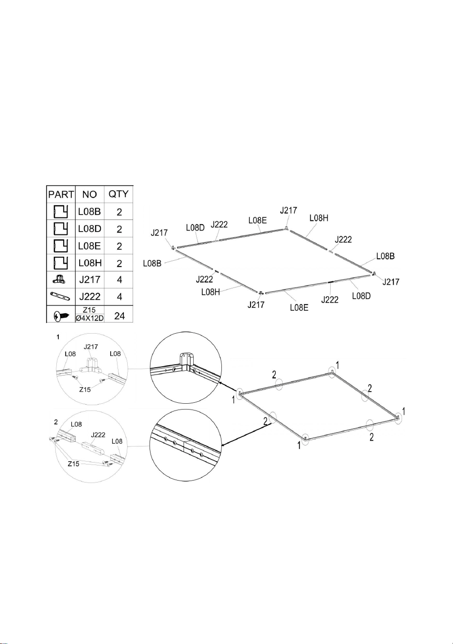
13
Växthusförsamling
Steg 1:
Se bilden för platsen för de delar som krävs för installation i detta steg.
Hörn: Montera del "J217" & "L08" med del "Z15" .
Anslutning av aluminiumstång: Efter att de två aluminiumstängerna är anslutna med del
"J222" , de är fixerade med del "Z15".
Steg 2:
Om du planerar att fästa ditt växthus på fast mark kan du följa det här steget för att göra ditt
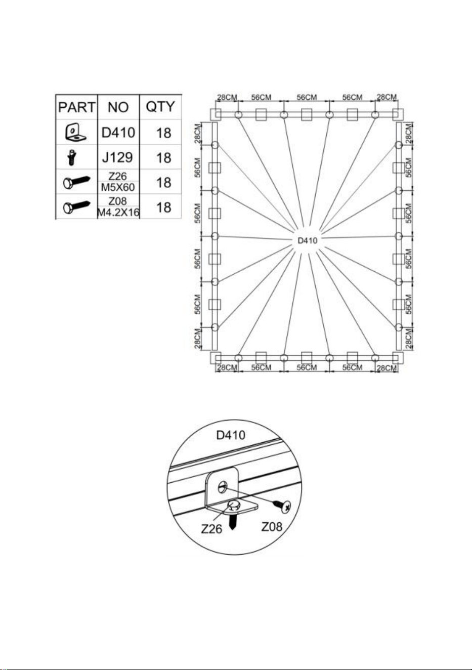
14
växthus säkrare.
Installationspositionen för anslutningsdelen " D410" visas i följande figur.
Om du planerar att fästa växthuset på trägolvet, se figuren nedan för att ansluta trägolvet till
växthuset med hjälp av del "D410" , "Z08" och "Z26".
Om du planerar att installera den på ett fast golv , till exempel betong. Bestäm först platsen
för hålet som ska borras, använd elverktyget för att borra hålet med en diameter på 8 mm,
använd en hammare eller liknande verktyg för att slå del "J129" i marken och använd
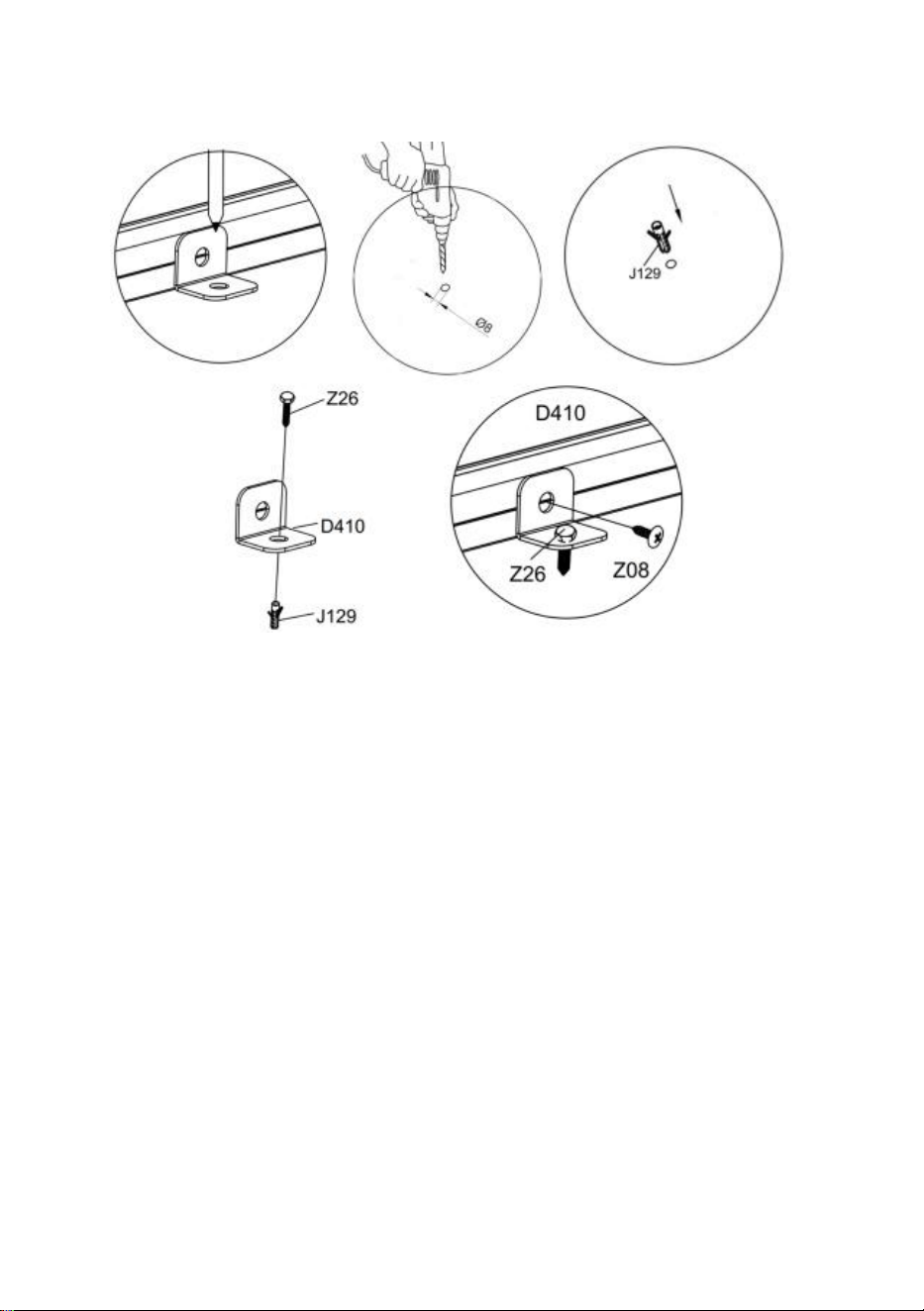
15
slutligen del "D410", "Z26" & "Z08" för att ansluta golvet till växthuset.
Steg 3:
Montera del " L01A " , " L01B " , " L01E " & " L01F " till komponenterna som slutfördes i steg
1 med del "Z15" .

16
Steg 4 :
Efter de två delarna " L07B " är anslutna med del "J222" , de är fixerade med del "Z15".
Efter att två delar "L07B" är anslutna, installera dem tillsammans med del "J218" enligt
slutet av diagrammet och säkra dem med del "Z15".
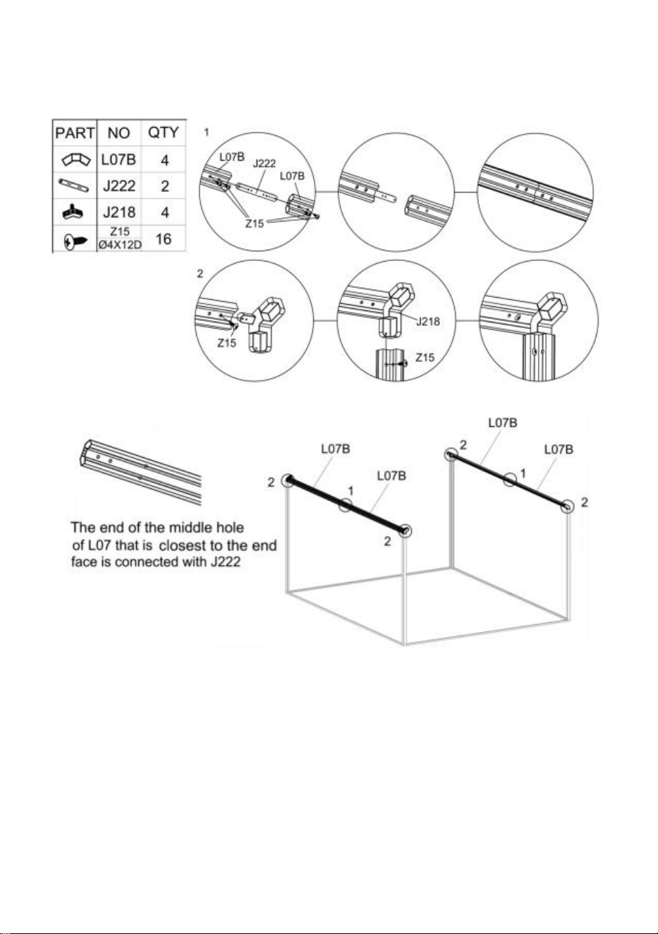
17
Efter installationen av "L07" -komponenten, installera den på ramen som slutfördes i
föregående steg enligt figuren.
Steg 5 :
Använd del " S26 " för att installera art " L03A " , " L03B " , " L03C " , " L04A " & " L04B " med
komponenterna färdigställda i det sista steget .
Sätt in del "Y5" i motsvarande position som visas.
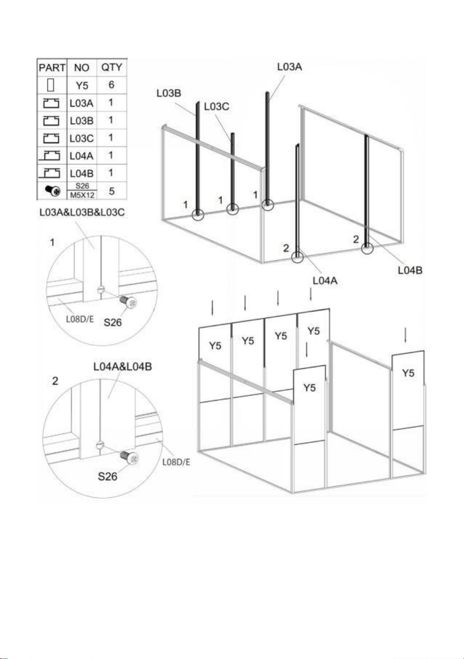
18
Steg 6 :
Använd del " S26 " för att installera art " L02F " , " L02G " och " L05A " med komponenterna
slutförda i det sista steget .
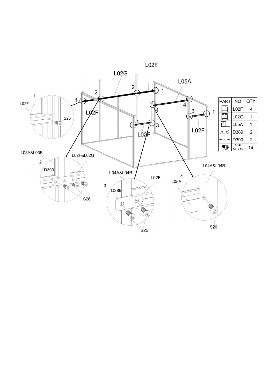
19
Detalj Figur 1 : Använd en del " S26 " för att ansluta del " L02F " och ram.
Detalj Figur 2: Använd del " S26 " & " D390 " för att ansluta del " L02F " , " L02G " och ram.
Detalj Figur 3: Använd del " S26 " & " D389 " för att ansluta del " L02F " och ram.
Detalj Figur 4: Använd en del " S26 " för att ansluta del " L05A " och ram.
Steg 7 :
Obs : Var noga med att kontrollera positionen för delarna "L02A" och "L02J", vilket
kommer att påverka den efterföljande installationen av Windows.
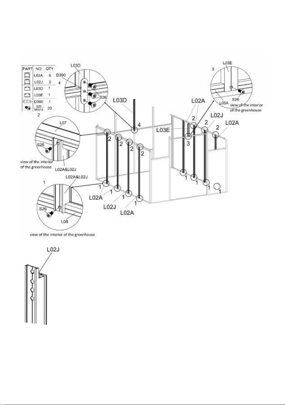
20
Använd del " S26 " för att ansluta del " L02A " eller " L02J " och ram.
Använd del " S26 " för att ansluta del " L03E " och ram.
Använd del " S26 " & " D390 " för att ansluta del " L03D " och ram.
OBS : installera del "L02J" med änden med fler hål vänd uppåt.
Steg 8 :
Sätt in del "Y 1 " , "Y 2 " , "Y 3 " , "Y 4 " , "Y 13 " , "Y 14 " & "Y 6 " i motsvarande position som
visas.

21
Steg 9 :
Efter del s " L01C " & " L01D " är anslutna med del "J22 0 " , de är fixerade med del "Z15".
Installera L01-komponenten på ramen färdig i steg 8 enligt figuren, och använd del "Z15"
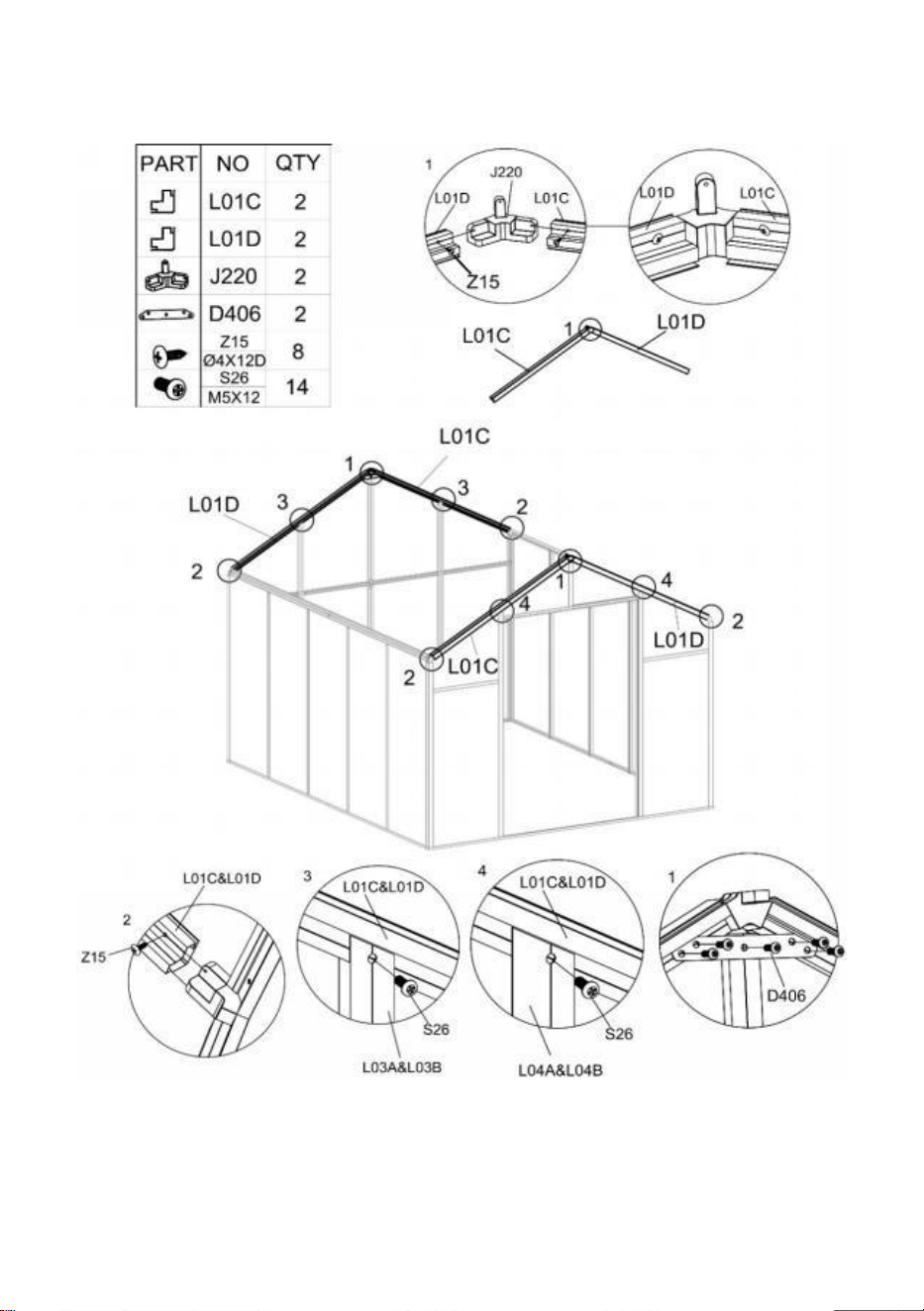
22
och "S26" för att låsa den efter anslutning.
Installera del "D406" på komponenten i L01 med del "S26".
Steg 10 :
Efter de två delarna " L06B " är anslutna med del "J222" , de är fixerade med del "Z15".
Efter installationen av "L0 6 " -komponenten, installera den på ramen som slutförts i
föregående steg enligt figuren och fixerad med del "Z15".
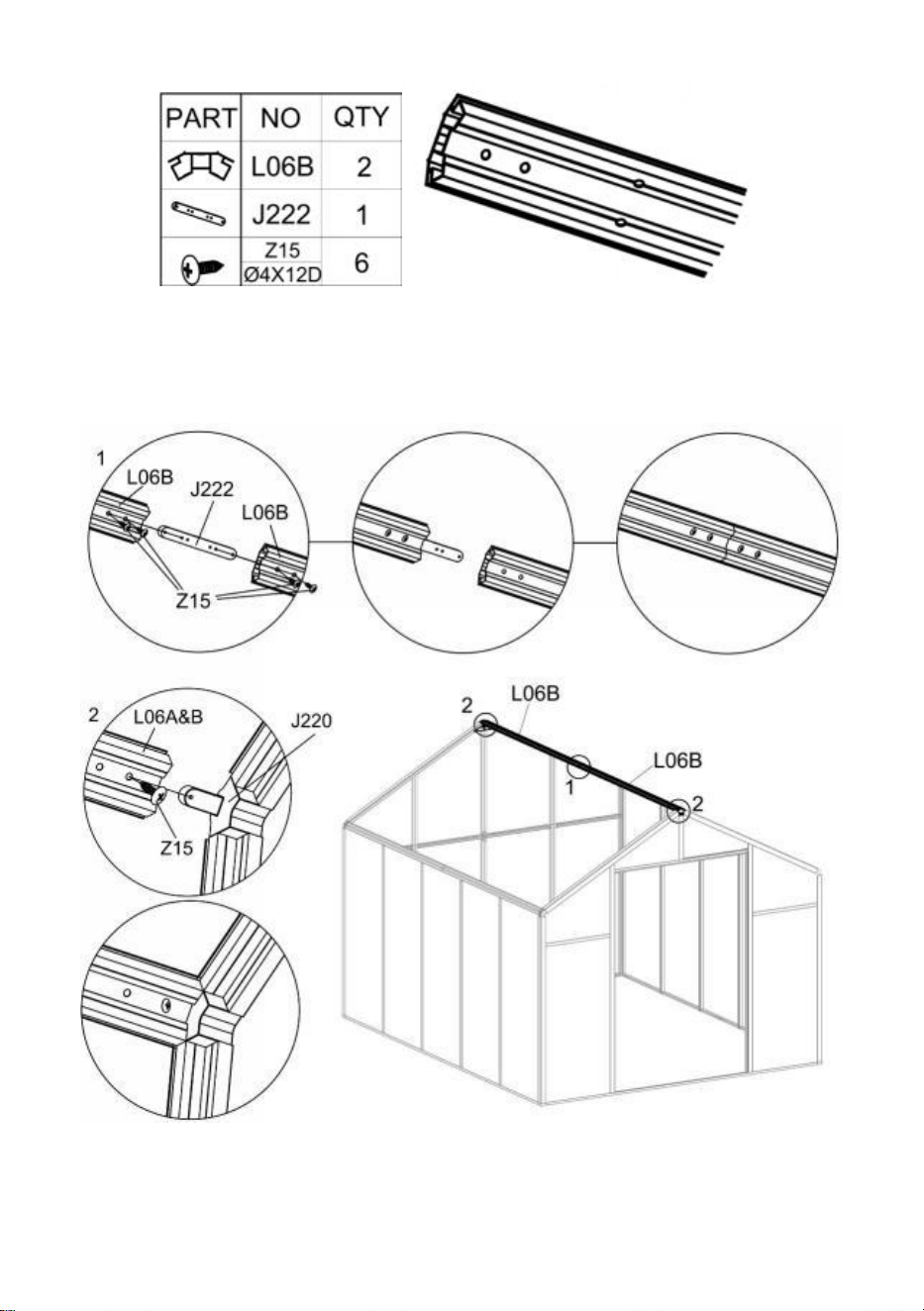
23
OBS : Änden av mitthålet på del “ L06 ” som är närmast ändytan är ansluten till del
“ J222 ” .
Steg 11 :
I det inre av växthuset, placera del "L02E" mellan delarna "L06B" och "L07B" enligt
ritningen, och fäst dem tillsammans med "S26".

24
Anslut del "L02J" och "L02E" med "D387" med del "S26".
Anslut två delar "L02 E " med "D38 6 " med del "S26".
Steg 1 2 :
I det inre av växthuset, placera del "L02 B " eller "L02 C " mellan delarna "L06B" och "L07B"
enligt ritningen, och fäst dem tillsammans med "S26".

25
Observera
:
Del "L02B" och "L02C" måste installeras i enlighet med den visade positionen,
annars kommer det att påverka den efterföljande fönstermonteringen!
Efter att delarna "L02B" och "L02C" är ordentligt installerade, använd "D26" för att ansluta
de två "L06B" och använd "Z08" för att säkra.
Steg 1 3 :
Installera fönsterenheten "L11A" på ramen som gjordes i steg 12 ovan med hjälp av del
"Z08".
Använd Delarna "S26" & "D388" för att installera "L02H" på ramen.
Använd delen "M02" och "S26" och anslut fönstret till ramen med delen "A111".
Observera
:
När du installerar delen " A111 " , öppna och stäng fönstret och lås skruvarna
och muttrarna samtidigt. Annars kan det hända att fönstret inte byter smidigt efter att det har
fixats.

26

27
Steg 1 4 :
Sätt in delen "Y 7 " & "Y 8 " i motsvarande position enligt bilden.
Använd delarna "Z15" och "S26" för att installera "L09B" i det visade läget. Obs: Skruvarna
som används i figur 1 och 2 kommer att vara olika.
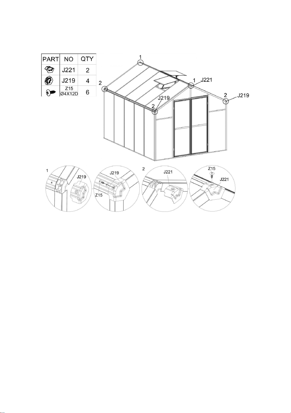
28
Steg 1 5 :
Montera "L09B" på ramen med hjälp av delarna "Z15" och "S26".
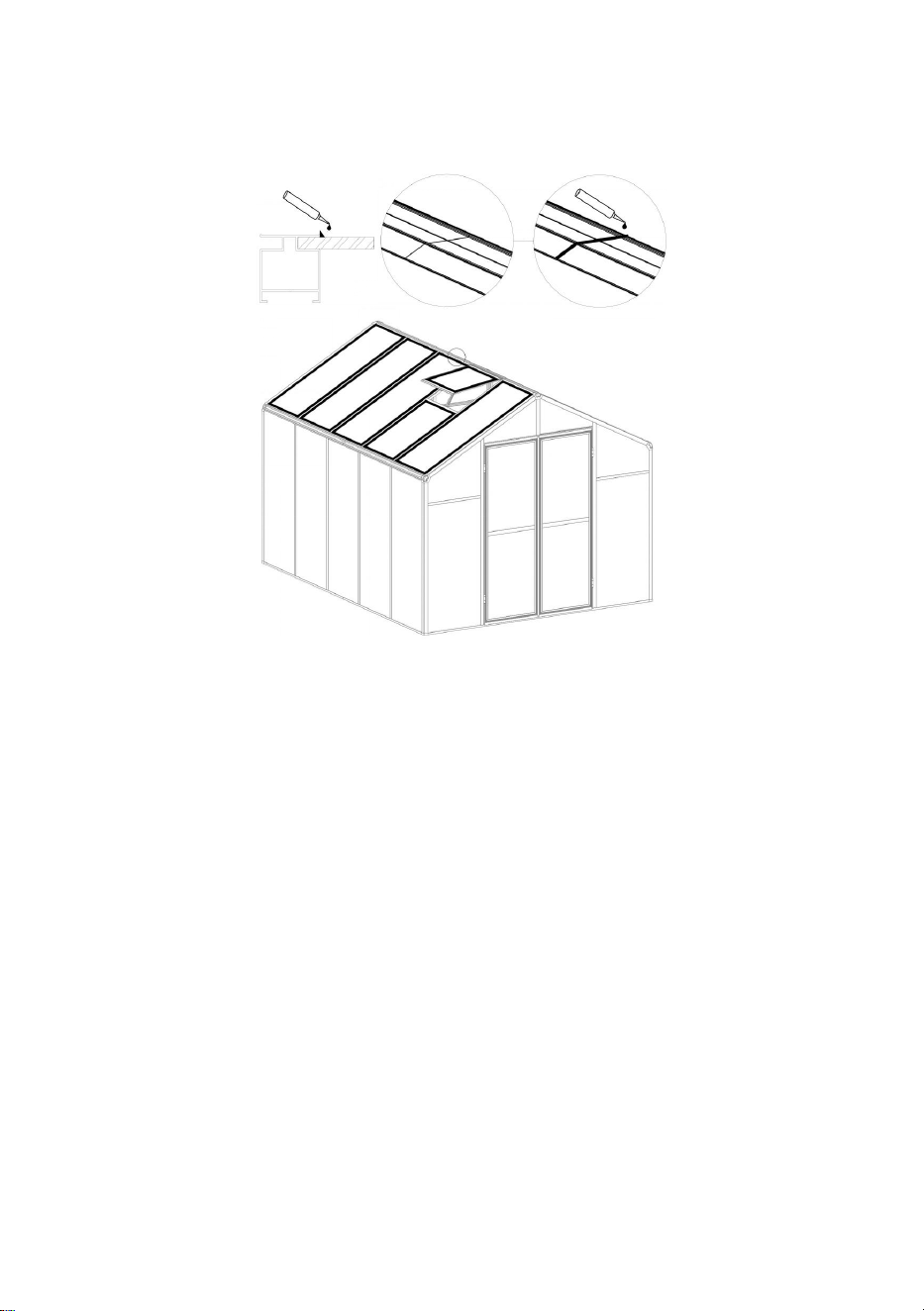
29
Steg 1 6 :
Enligt kundens behov appliceras silikon på mellanrummen mellan aluminiumet och plåten
på toppen av produkten, och mellanrummen mellan aluminiumet för att uppnå vattentäthet.
Steg 1 7 :
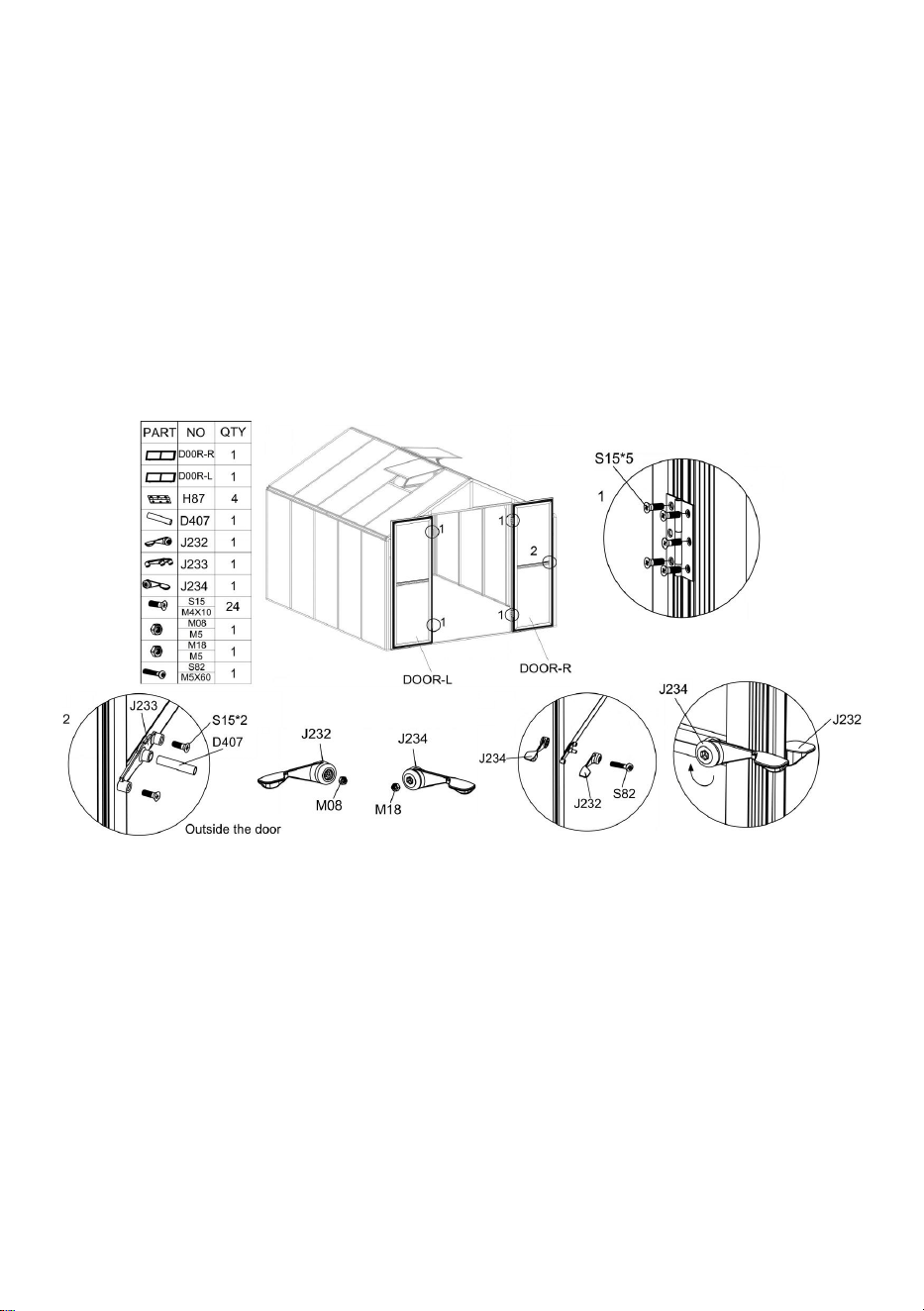
30
Montera dörren på karmen med hjälp av delarna " S 15" och " H87 ".
Notera: När du installerar dörren, justera främst positionen, försök att öppna och stänga
dörren under installationen, se till att dörren öppnas och stängs smidigt och lås sedan
skruvarna.
Använd del "S15" för att installera J233 på utsidan av dörren enligt bilden , sätt sedan in del
"D407" i motsvarande hål på "J233".
Placera delen "M08" och "M18" i motsvarande hål i "J232" respektive "J234".
Använd del "S82" för att installera "J232" och "J234" på båda sidor av dörren enligt figuren.
Om del "J232" och "J234" fortfarande är lösa efter att ha anslutits, tryck på "J232" och vrid
"J234" medurs.
Nu är installationen av växthuset klar. Njut av det !

31

Tillverkare: Shanghaimuxinmuyeyouxiangongsi
Adress: Shuangchenglu 803nong11hao1602A-1609shi, baoshanqu,
shanghai 200000 CN.
Importerad till AUS: SIHAO PTY LTD. 1 ROKEVA STREETEASTWOOD
NSW 2122 Australien
Importerad till USA: Sanven Technology Ltd. Suite 250, 9166 Anaheim
Place, Rancho Cucamonga, CA 91730