
Installation and User Manual
www.zlinekitchen.com
TOUCHSTONE REFRIGERATION
RWDO-GS-24, RWDPO-24, RBSO-GS-24,
RBSPO-24, RBSO-ST-24, RDSO-ST-24,
& RDSPO-24 MODELS

ZLINE Kitchen and Bath provides Attainable Luxury, where the kitchen and bath of your dreams
is never out of reach. Through our unique designs and unparalleled quality, we’re dedicated to
providing you an elevated experience in the heart of your home. With an endless selection of
features and finishes, our inspiration is your reality.

ZLINE is fueled by a passion for innovation; A relentless pursuit of bringing the
highest end luxury designs and professional features into everyone’s homes.
Because we continually strive to improve our products, we may change
specifications and designs without prior notice.
Scan the QR code to view the most up-to-date version of the Installation
Manual and User Manual.
WARNING: This product can expose you to chemicals including nickel, which is known to the
State of California to cause cancer. For more information, go to www.P65Warnings.ca.gov.

IMPORTANT SAFETY INSTRUCTIONS . . . . . . . . . . . . . . . . . . . . . . . . . . . . . .1
BEFORE INSTALLATION . . . . . . . . . . . . . . . . . . . . . . . . . . . . . . . . . . . . . . . . . .6
Product Specifications . . . . . . . . . . . . . . . . . . . . . . . . . . . . . . 6
Provided Materials . . . . . . . . . . . . . . . . . . . . . . . . . . . . . . .10
Materials Needed . . . . . . . . . . . . . . . . . . . . . . . . . . . . . . . .10
INSTALLATION . . . . . . . . . . . . . . . . . . . . . . . . . . . . . . . . . . . . . . . . . . . . . . . . 11
Built-In Cabinet Instructions . . . . . . . . . . . . . . . . . . . . . . . . . . .12
Installing the Anti-Tip System . . . . . . . . . . . . . . . . . . . . . . . . . .13
Reversing the Door Swing . . . . . . . . . . . . . . . . . . . . . . . . . . .14
Cooler Integrated Door Panel Installation . . . . . . . . . . . . . . . . . . .16
Drawer Integrated Door Panel Installation . . . . . . . . . . . . . . . . . . 20
Electrical Connection . . . . . . . . . . . . . . . . . . . . . . . . . . . . . 23
OPERATION . . . . . . . . . . . . . . . . . . . . . . . . . . . . . . . . . . . . . . . . . . . . . . . . . .24
Control Panel Layout and Operation . . . . . . . . . . . . . . . . . . . . . .24
Error Alarms . . . . . . . . . . . . . . . . . . . . . . . . . . . . . . . . . . .29
Energy-Saving Tips and Other Notes . . . . . . . . . . . . . . . . . . . . 30
CARE AND MAINTENANCE . . . . . . . . . . . . . . . . . . . . . . . . . . . . . . . . . . . . . 31
TROUBLESHOOTING . . . . . . . . . . . . . . . . . . . . . . . . . . . . . . . . . . . . . . . . . . .33
WARRANTY . . . . . . . . . . . . . . . . . . . . . . . . . . . . . . . . . . . . . . . . . . . . . . . . . . .34
TABLE OF CONTENTS

1
IMPORTANT SAFETY INSTRUCTIONS
• IMPORTANT: Read all instructions before using this appliance. Use this appliance
only for its intended purpose as described in this manual. Always exercise basic safety
precautions, as described below. After reading this manual, store it in an accessible
place where users and services can easily reference it.
• The purpose of these safety precautions is to ensure safe and correct use of the product to
minimize risks that could cause serious damage and injury to you or others. Precautions
are split into WARNINGS and CAUTIONS. Incidences where improper handling of
the unit could lead to death or serious injury are listed under the WARNING heading.
Incidences listed under CAUTION could lead to serious injury.
DANGER
Risk of fire or explosion. FLAMMABLE REFRIGERANT used.
• Do not use mechanical devices to defrost refrigerator.
• Do not puncture refrigerant tubing.
• This appliance is to be repaired only by trained service personnel.
• Consult the appliance’s user and installation manuals before attempting service.
• All safety precautions must be followed.
CAUTION
CAUTION - Risk of fire or explosion. Dispose of refrigerator properly in
accordance with the applicable federal or local regulations. Flammable
refrigerant used.
CAUTION
Risk of fire or explosion if refrigerant tubing is punctured. FLAMMABLE
REFRIGERANT used. Follow handling instructions carefully.
DANGER
DANGER - Risk of fire or explosion. Flammable refrigerant used. Do not use
mechanical devices to defrost refrigerator. Do not puncture refrigerant tubing.
WARNING
Do not use mechanical devices or other means to accelerate the defrosting
process, other than those recommended by the manufacturer.
WARNING
Keep ventilation openings, in the appliance enclosure or in the built-in structure,
clear of obstruction.
General Safety

2
IMPORTANT SAFETY INSTRUCTIONS
WARNING
Do not damage the refrigerant circuit.
WARNING
Do not use electrical appliances inside the food storage compartments of the
appliance unless they are explicitly recommended by the manufacturer.
DANGER
DANGER - Risk of fire or explosion. Flammable refrigerant used. To be repaired
only by trained service personnel. Use only manufacturer-authorized service
parts. Any repair equipment used must be designed for flammable refrigerants.
Follow all manufacturer repair instructions. Do not puncture refrigerant tubing.
CAUTION
CAUTION - Risk of fire or explosion due to puncture of refrigerant tubing; follow
handling instructions carefully. Flammable refrigerant used.
WARNING
WARNING: Do not locate multiple portable socket-outlets or portable power
supplies at the rear of the appliance.
WARNING
• Installation and service should be performed by a qualified installer. The appliance should
not be adjusted or repaired by anyone except qualified service personnel. Attempting to
perform these yourself could result in fire, malfunction, or injury.
• Never splash water directly onto the appliance or wash it with water without unplugging
it from power, as a short circuit could result. If the appliance is installed outdoors in a
humid or rainy environment, a water-proof covering is recommended.
• Never store flammable, explosive, or volatile substances inside or on top of the unit, as
an explosion and fire could result.
• Do not damage, modify, excessively bend, strain, twist or bundle the power cord. Avoid
hot, sharp, or aggressive surfaces. Placing heavy objects on the cord or binding it could
damage the cord, possibly resulting in electrical shock and/or fire.
• Use a dedicated wall outlet. Do not use an extension cord or multiple-outlet adapter, as
this could result in electrical shock, overheating, and fire.
General Safety

3
General Safety
IMPORTANT SAFETY INSTRUCTIONS
• Never use flammable spray cans or leave flammable substances near the unit. Sparks
from electrical switches could result in an explosion and/or fire.
• If a combustible gas is present near the appliance, turn off the source of the gas, then
open the windows and doors to allow the gas to dissipate. To avoid an explosion, do
not pull the plug or switch off the unit.
• The electrical socket must be properly grounded and the plug should always be
accessible. The ground wire cannot be connected with a gas pipe, heating pipe, water
pipe, telephone line, or lightning rod. It cannot be replaced with the neutral wire of
single-phase power.
• For standard indoor installation, it’s recommended that a dedicated electrical circuit
suitable for a NEMA 5-15 outlet serving only your appliance be used; please ensure
the outlet is easily accessible.
• In addition to the ground wire, an electrical leakage circuit breaker is required if the unit
is installed outdoors.
• An electrician-installed ground fault circuit interrupter (GFCI) electrical outlet is also
required for outdoor installation. If no GFCI is installed, electrical shock could result.
• Never climb onto or inside the unit. The unit could tip over or fall and cause material
damage or personal injury.
• Disconnect the power cord plug from the wall outlet before moving the unit and make
sure that the power cord is not damaged during transport. A damaged power cord
could result in electrical shock and/or fire.
• Never unplug the unit by pulling on the power cord. Always grip the plug firmly and
pull straight out from the outlet. Pulling the cord could cause wire breakage, possibly
resulting in overheating and fire. Never pull out plug when hands are wet.
• Have a qualified technician repair or replace any cord that is frayed or damaged. Do
not use a cord that shows cracks or abrasions along its length.

4
IMPORTANT SAFETY INSTRUCTIONS
• Keep the appliance’s ventilation openings, whether in the appliance enclosure or in the
built-in structure, clear of any obstruction.
CAUTION
• This unit must be properly installed in accordance with the installation instructions
including in this manual, along with adhering to all local government codes, before it is
used. See electrical instructions on page 23.
• This appliance can either be built-in or freestanding. Built-in units vent air out of the
grill located at the bottom front of the refrigerator. To ensure proper service access and
ventilation, all units should not have the grill openings covered. There are no additional
requirements for venting at the top, side or rear of the unit.
• Install the unit in a location where the floor is sturdy enough to support the load of the
unit. If the floor is not sturdy enough or installation is incorrectly performed, the unit could
tip over and cause personal injury. If the unit is placed on a stand, the front surface must
be 3" (76 mm) or more back from the edge of the stand to avoid accidental tipping of
the appliance during normal usage.
• Never place heavy objects or items containing water on top of the unit. Objects could
fall and cause injury, and spilled water or other liquids could cause the deterioration of
the insulation of electrical components and result in electrical shock.
• Disconnect the unit if it is behaving abnormally, and do not reconnect until the situation
is corrected. If normal troubleshooting measures do not work, contact ZLINE at
1-614-777-5004 for assistance.
• Unplug the appliance before doing any maintenance to avoid electric shock.
• This unit is not intended for the storage of medicines, vaccines, or chemical reagents.
• Keep all packing materials away from children.
WARNING
Risk of child entrapment. To avoid safety and suffocation risks for children or
pets, before you dispose of the appliance, take off the doors and drawers and
leave the shelves in place so children or pets may not climb inside.
General Safety

5
IMPORTANT SAFETY INSTRUCTIONS
Disposal Safety
• Condenser water from the appliance evaporator drains into a hole in the floor of the
storage compartment and is channeled into a drain pan located at the back of the
appliance on the compressor. Heat transferred from the compressor evaporates any
water that has collected in the pan. Be sure the drain hole in the floor of the unit is clear
and unobstructed.
• This appliance is CFC- and HFC-free and contains small quantities of isobutane (R600a),
an environmentally friendly refrigerant.
• During long absences, remove the unit’s contents, unplug the unit, clean it, and leave the
door open slightly to avoid possible formation of condensation, mold, or odors. Use a
cover to protect the unit and prolong its lifespan.
• Leave disassembly and disposal of the unit to qualified experts. The manufacturer will not
be responsible for any damage to property or to persons caused by incorrect installation,
improper use of the appliance, or failure to heed the warnings listed, and the warranty
will be voided.
• The manufacturer reserves the right to make changes to its products when considered
necessary and useful, without affecting the essential safety and operating characteristics.
• This appliance has been designed for non-commercial, domestic use only.
• Please observe all local, state, and national codes and ordinances. Please ensure the
appliance is properly grounded. The plug should always be accessible.
• Never use an appliance with a damaged cooling system. If system is damaged upon
arrival, contact ZLINE at 1-614-777-5004
DISPOSAL
The appliance cannot be treated as normal domestic trash and must be disposed of at a
collection point for recycling electric and electronic appliances. Your contribution to the
correct disposal of this product protects the environment. Further information about the
recycling of this product can be obtained from your local municipal authority.
6
Product Specifications
BEFORE INSTALLATION
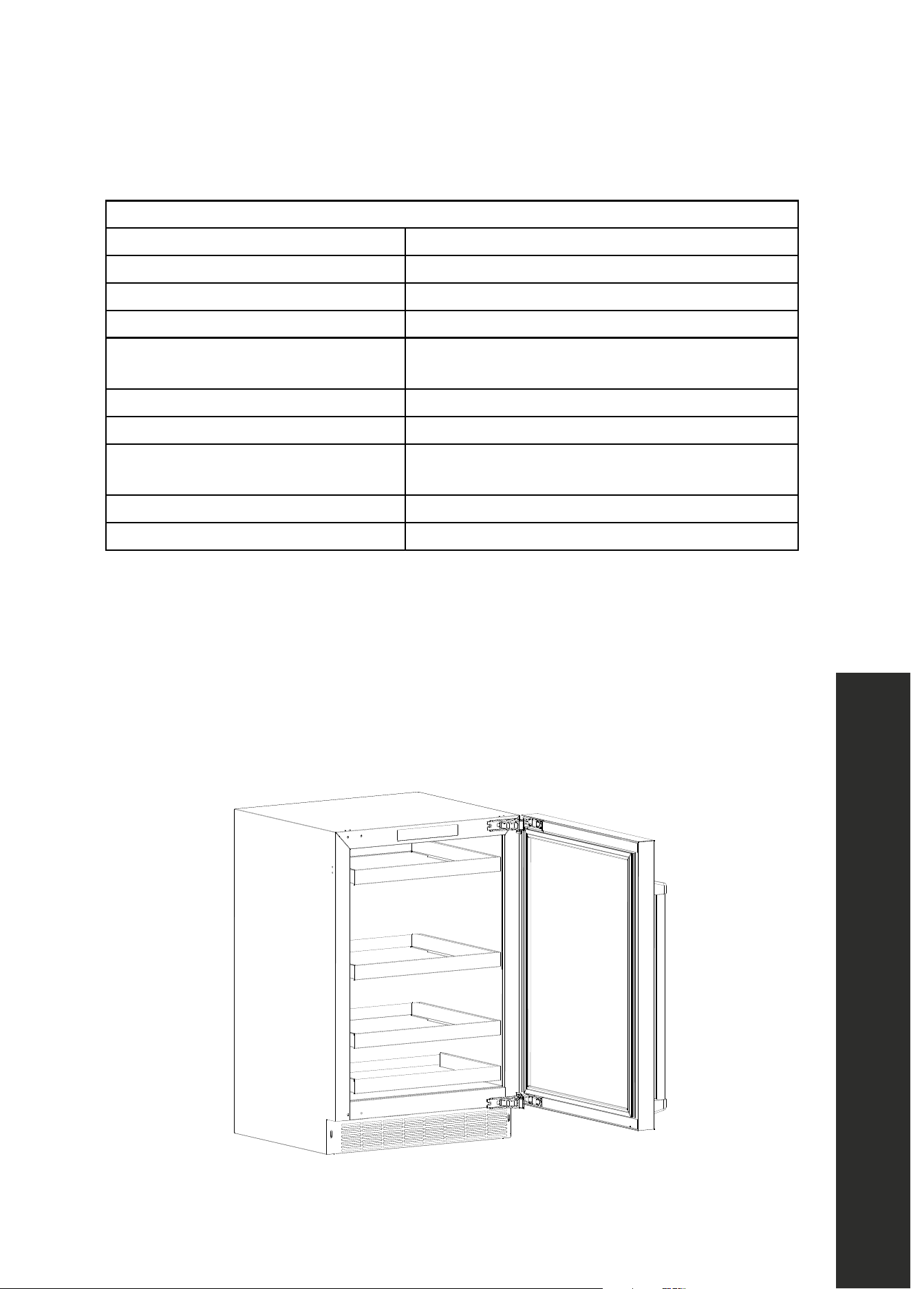
PRODUCT SPECIFICATIONS
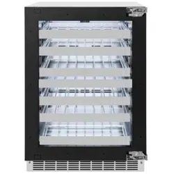
Model RWDO-GS-24 RWDPO-24
Description
Dual-Zone Wine Cooler
Stainless Steel Glass Door
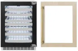
Dual-Zone Wine Cooler
Panel-Ready Glass Door
Weight 169 lb (77 kg) 161 lb (73 kg)
Voltage/Frequency/Max Amp Draw 115-120VAC/60Hz/15A
*Product Dimensions
23 7/8" W × 23 3/16" D × 34" H
606 mm W x 589 mm D x 864 mm H
Ambient Temperature Range 50 °F–110 °F (10 °C–43 °C)
Operating Temperature Range Both zones: 40 °F–65 °F (4 °C–18 °C)
Shelf Configuration
5 Full Depth Stainless Steel Wire Rack
1 Half Depth Stainless Steel Wire Rack (at bottom)
Interior Capacity 4.8 cu. ft.
Wine Storage Capacity 44 Bordeaux-style bottles (750 ml)
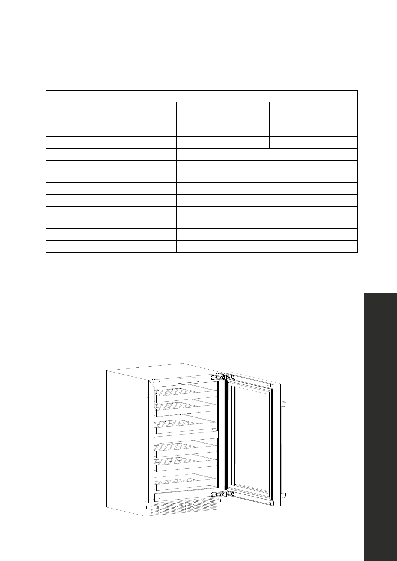
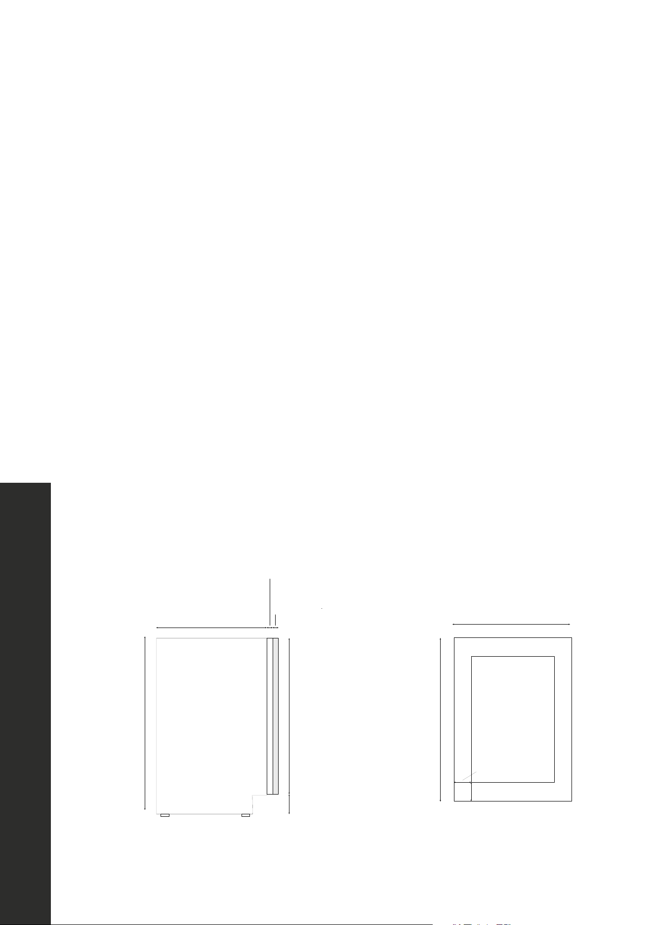
*PRODUCT DIMENSION NOTES:
• Height for both models varies depending on adjustable legs; 34" (864 mm) is the
minimum height with the legs at their lowest position. Max height is 34 15/16" (887 mm).
• The diagram below represents an RWDO-GS-24 model. The 23 3/16" (589 mm) depth
measurement is from back of the cooler to the front of the stainless steel door.
• For RWDPO-24, depth to the front of the panel-ready door is 22 3/8" (568 mm).
• Full depth including handle is 25 7/16" (646 mm).
7
BEFORE INSTALLATION
PRODUCT SPECIFICATIONS
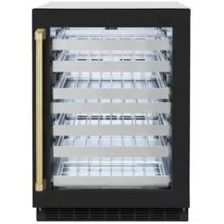
Model RBSO-GS-24 RBSPO-24
Description
Beverage Center
Stainless Steel Glass Door
Beverage Center
Panel-Ready Glass Door
Weight 154 lb (70 kg) 147 lb (67 kg)
Voltage/Frequency/Max Amp Draw 115VAC/60Hz/15A
*Product Dimensions
23 7/8" W × 23 3/16" D × 34" H
606 mm W x 589 mm D x 864 mm H
Ambient Temperature Range 50 °F–110 °F (10 °C–43 °C)
Operating Temperature Range 34 °F–65 °F (1 °C–18 °C)
Shelf Configuration
1 Full Depth Stainless-Steel Wire Rack
Glass Shelves: 2 Full Depth and 1 Half Depth
Interior Capacity 5.2 cu. ft.
Can/Bottle Storage Capacity 151 cans or 79 bottles (12 oz)
Wine Storage Capacity 8 Bordeaux-style bottles (750 ml)
*PRODUCT DIMENSION NOTES:
• Minimum height for both models is 34" (864 mm). Max height is 34 15/16" (887 mm).
• The diagram below represents an RBSO-GS-24 model. The 23 3/16" (589 mm) depth
measurement is from back of the cooler to the front of the stainless steel door.
• For RBSPO-24, depth to the front of the panel-ready door is 22 3/8" (568 mm).
• Full depth including handle is 25 7/16" (646 mm).
Product Specifications
8
Product Specifications
BEFORE INSTALLATION
PRODUCT SPECIFICATIONS
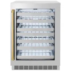
Model RBSO-ST-24
Description Stainless Steel Solid Door Refrigerator
Weight 139 lb (63 kg)
Voltage/Frequency/Max Amp Draw 115VAC/60Hz/15A
*Product Dimensions
23 7/8" W × 23 3/16" D × 34" H
606 mm W x 589 mm D x 864 mm H
Ambient Temperature Range 50 °F–110 °F (10 °C–43 °C)
Operating Temperature Range 34 °F–65 °F (1 °C–18 °C)
Shelf Configuration
3 Full Depth Glass Shelves
1 Half Depth Glass Shelf (at bottom)
Interior Capacity 5.2 cu. ft.
Can/Bottle Storage Capacity 151 cans or 103 bottles (12 oz)
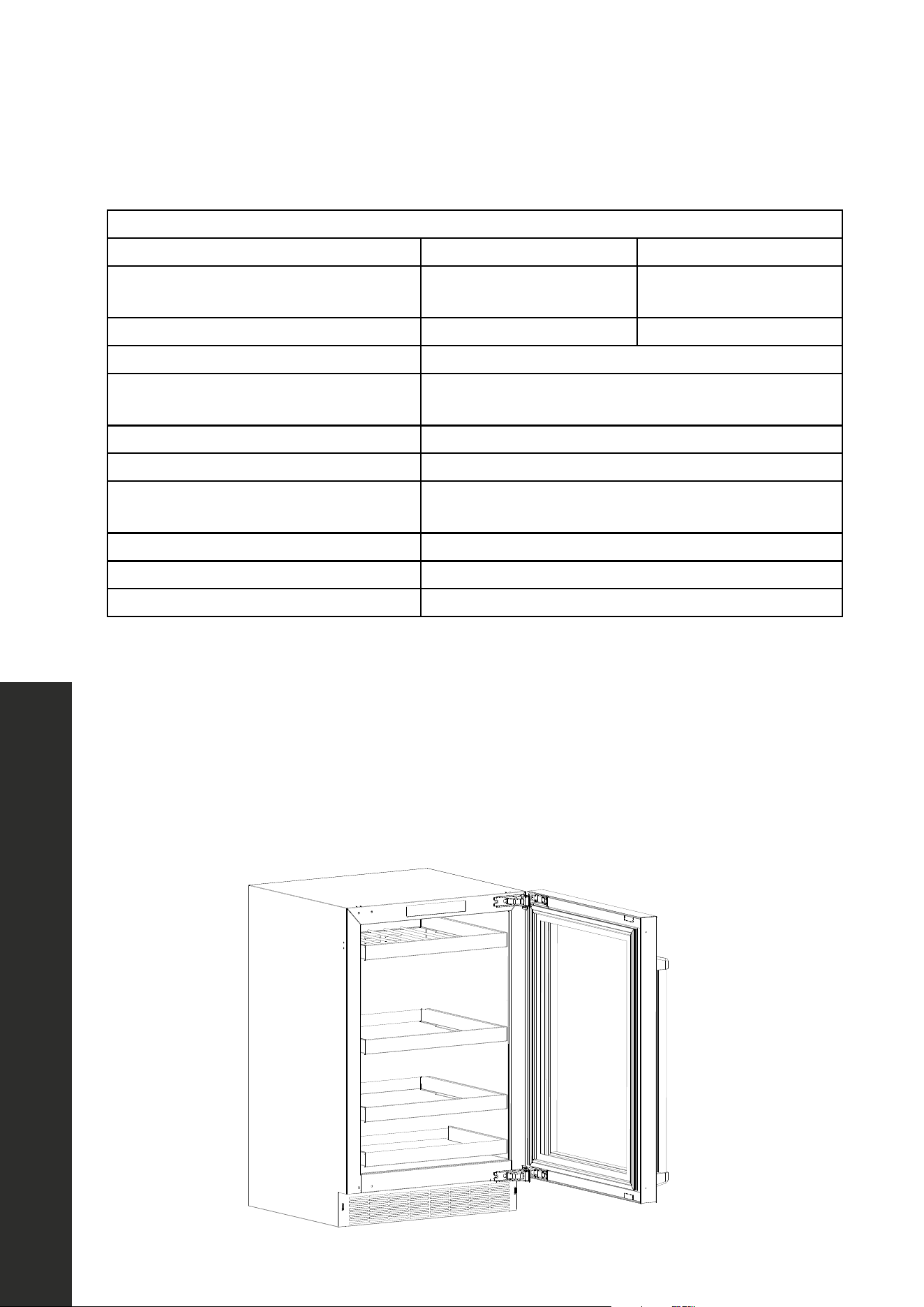
*PRODUCT DIMENSION NOTES:
• Minimum height for the refrigerator is 34" (864 mm).
• Max height is 34 15/16" (887 mm).
• The 23 3/16" (589 mm) depth measurement is from back of the cooler to the front of the
stainless steel door.
• Full depth including handle is 25 7/16" (646 mm).
9
BEFORE INSTALLATION
PRODUCT SPECIFICATIONS
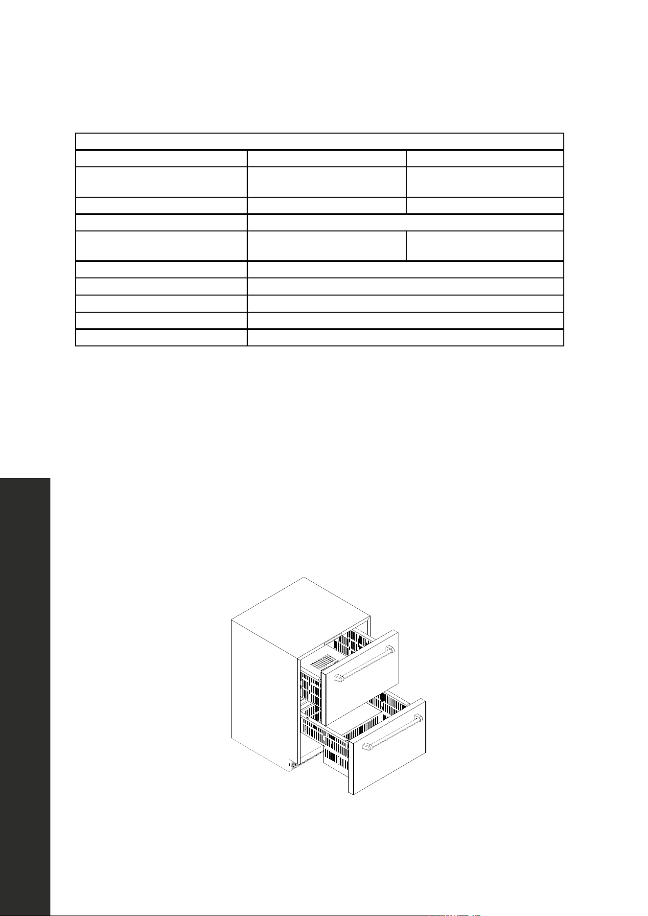
Model RDSO-ST-24 RDSPO-24
Description
Refrigerator Drawer
Solid Stainless Steel Door
Refrigerator Drawer
Panel-Ready Door
Weight 127 lb (58 kg) 122 lb (55 kg)
Voltage/Frequency/Max Amp Draw 115VAC/60Hz/15A
*Product Dimensions
23 7/8" W × 23 3/16" D × 34" H
606 mm W × 589 mm D × 864 mm H
23 7/8" W × 22 7/16" D × 34" H
606 mm W × 570 mm D × 864 mm H
Ambient Temperature Range 50 °F–110 °F (10 °C–43 °C)
Operating Temperature Range 34 °F–65 °F (1 °C–18 °C)
Shelf Configuration 2 Full Depth Stainless-Steel Drawers
Interior Capacity 4.6 cu. ft
Can/Bottle Storage Capacity 168 cans or 100 bottles (12 oz)
*PRODUCT DIMENSION NOTES:
• Max height is 34 15/16" (887 mm).
• For RDSO-ST-24, the depth of 23 3/16" (589 mm) is from back of the refrigerator to the
front of the stainless steel drawers.
• For RDSPO-24, the depth to the front of the panel-ready drawer is 22 3/8" (568 mm).
Depth with overlay panel is 23 1/8" (587 mm).
• Full depth including handle is 25 5/16" (643 mm).
• Depth of the refrigerator cabinet only is 20 5/8" (524 mm).
• Depth with the drawers open and including the handle is 41 1/16" (1043 mm).
Model RDSO-ST-24 RDSPO-24
Description 24'' Drawer Refrigerator
Weight 127lb (57.6Kg) 121lb (55Kg)
Voltage/Frequency/Max
Amp Draw
115VAC/60Hz/15A
*Product Dimensions
23 7/8" W × 23 3/16" D × 34" H
606mm W × 589mm D × 864mm H
23 7/8" W × 22 7/16" D × 34" H
606mm W × 570mm D × 864mm H
Ambient Temperature
Range:
50 °F–110 °F (10 °C–43 °C)
Operating Temperature
Range
34 °F–65 °F (1 °C–18 °C)
Drawer Configuration 2 Full Depth Stainless-Steel Drawer
Interior Capacity 4.5 cu.ft.
Can/Bottle Storage
Capacity
168 cans or 100 bottles (12 oz)
Product Specifications
10
Materials Provided and Needed
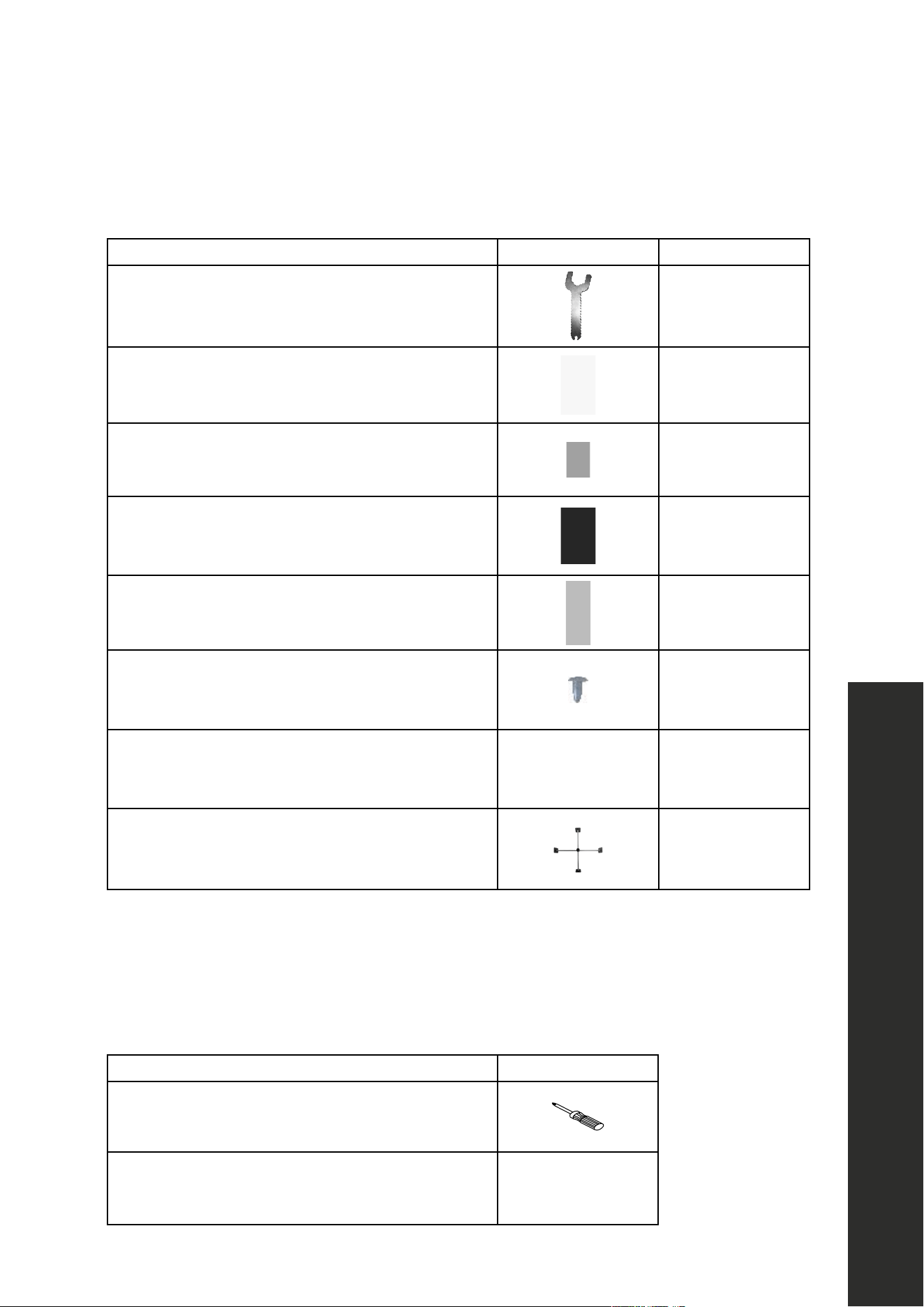
PROVIDED MATERIALS
DESCRIPTION IMAGE QUANTITY
Foot adjustment wrench
1
Anti-tip brackets
2
Screws for anti-tip brackets
6
*Door limiting pins
2
**Screws for custom panel installation
10
Decorative plugs
4
Allen key
1
Divider
1
*Not needed for RDSO-ST-24 and RDSPO-24 refrigerator drawer models.
**Not needed for stainless steel door models; see page 16 for panel-ready information.
MATERIALS NEEDED
DESCRIPTION IMAGE
Phillips-head screwdriver
Drill with Phillips-head bit
BEFORE INSTALLATION

11
INSTALLATION
BEFORE INSTALLING YOUR APPLIANCE
• Remove all exterior and interior packing and dispose appropriately.
• Before connecting the unit to the power source for the first time, let it stand upright for
approximately 4 hours. This will reduce the possibility of a malfunction in the sealed
cooling system from handling during transportation.
• Clean the interior surface with lukewarm water using a soft cloth and wipe dry.
INSTALLATION OF YOUR APPLIANCE
• This appliance is designed for freestanding, recessed, or built-in installation (fully
recessed). Built-in installation is recommend to reduce risk of tipping.
• Place your appliance on a floor that is strong enough to support it when it is fully loaded.
To level your appliance, adjust the front leveling legs at the bottom of the appliance with
the provided wrench. Legs can be adjusted up to 1" (25 mm).
• Install the appliance in a location away from direct sunlight and sources of heat (stove,
heater, radiator, etc.). Direct sunlight may affect the acrylic coating, and heat sources
may increase electrical consumption. Extreme cold ambient temperatures may also
cause the unit not to perform properly.
• Plug the appliance into a dedicated, properly installed and grounded outlet. Do not
under any circumstances cut or remove the third (ground) prong from the power cord.
Any questions concerning power and/or grounding should be directed toward a
certified electrician or an authorized ZLINE service provider.
• While appliances are approved for outdoor use, it’s recommended to avoid installing
units in overly moist or humid areas. Too much moisture in the air will cause frost to form
quickly on the evaporator requiring more frequent defrosting of the refrigerator.
• RWDO-GS-24, RWDPO-24, RBSO-GS-24, RBSPO-24, and RBSO-ST-24 units come
with doors installed at the pre-set maximum door swing of 135°. If you desire to limit the
door swing to 90°, insert the 2 provided door limiting pins into the pin hole on the top
and bottom door hinges, as show in the image below.
Door Limiting Pin Location
Pre-Installation Procedure
12
Cabinet Specifications
INSTALLATION
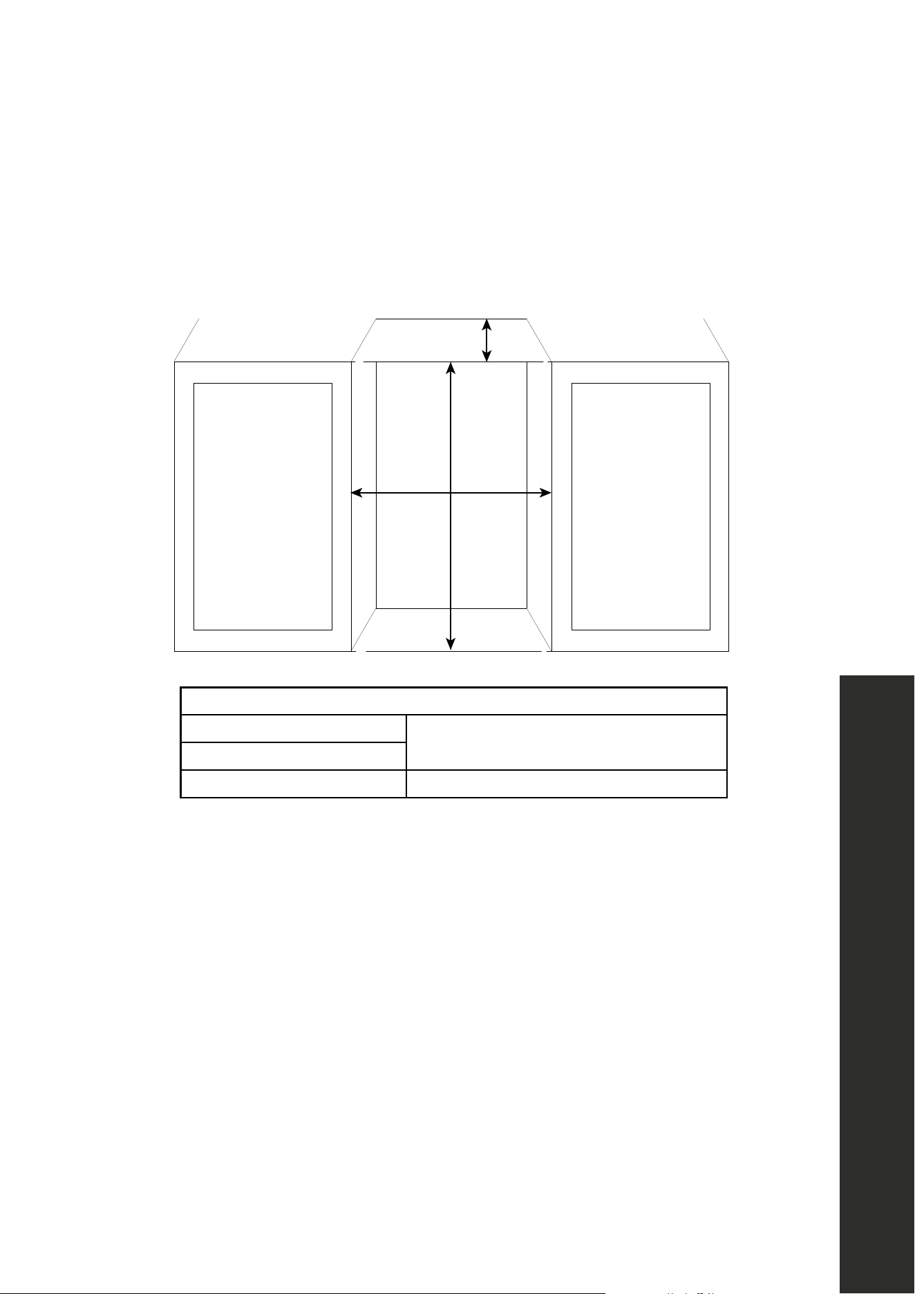
BUILT-IN CABINET INSTRUCTIONS
While this unit is designed for both built-in and freestanding installation, built-in installation
is recommended to reduce risk of tipping. If you plan to use this unit in a built-in application,
please follow the cabinet cutout requirements shown below.
Depth
Height
Width
RECOMMENDED CABINET OPENING DIMENSIONS
Width
24" (610 mm)
Depth
Height 34 1/8"–35 1/8" (867 mm–892 mm)
ADDITIONAL INSTALLATION NOTES:
• The height cut-out variance takes into account the minimum and maximum height of the
unit (34"–34 15/16" or 864 mm–887 mm) depending on the legs being at their lowest
and highest setting. Since kitchen cabinet layouts vary, consult a professional installation
technician when considering a built-in cabinet installation.
• Depth is based off standard cabinet depths of 24" (610 mm) and also allows for ample
space at the rear of the unit for the electrical cord to be plugged into a properly installed
dedicated wall outlet.
• RWDO-GS-24, RWDPO-24, RBSO-GS-24, RBSPO-24, and RBSO-ST-24 units should
be installed a minimum of 11" (280 mm) away from a side wall. This distance is required
to obtain full swing (135°) of the door.
• If using limiting pins to obtain a 90° door swing (for non refrigerator drawer models), the
minimum distance the appliance should be installed when adjacent to a wall is 2 3/4"
(70 mm); this ensures enough room for the handle to not hit the wall.
13
INSTALLATION
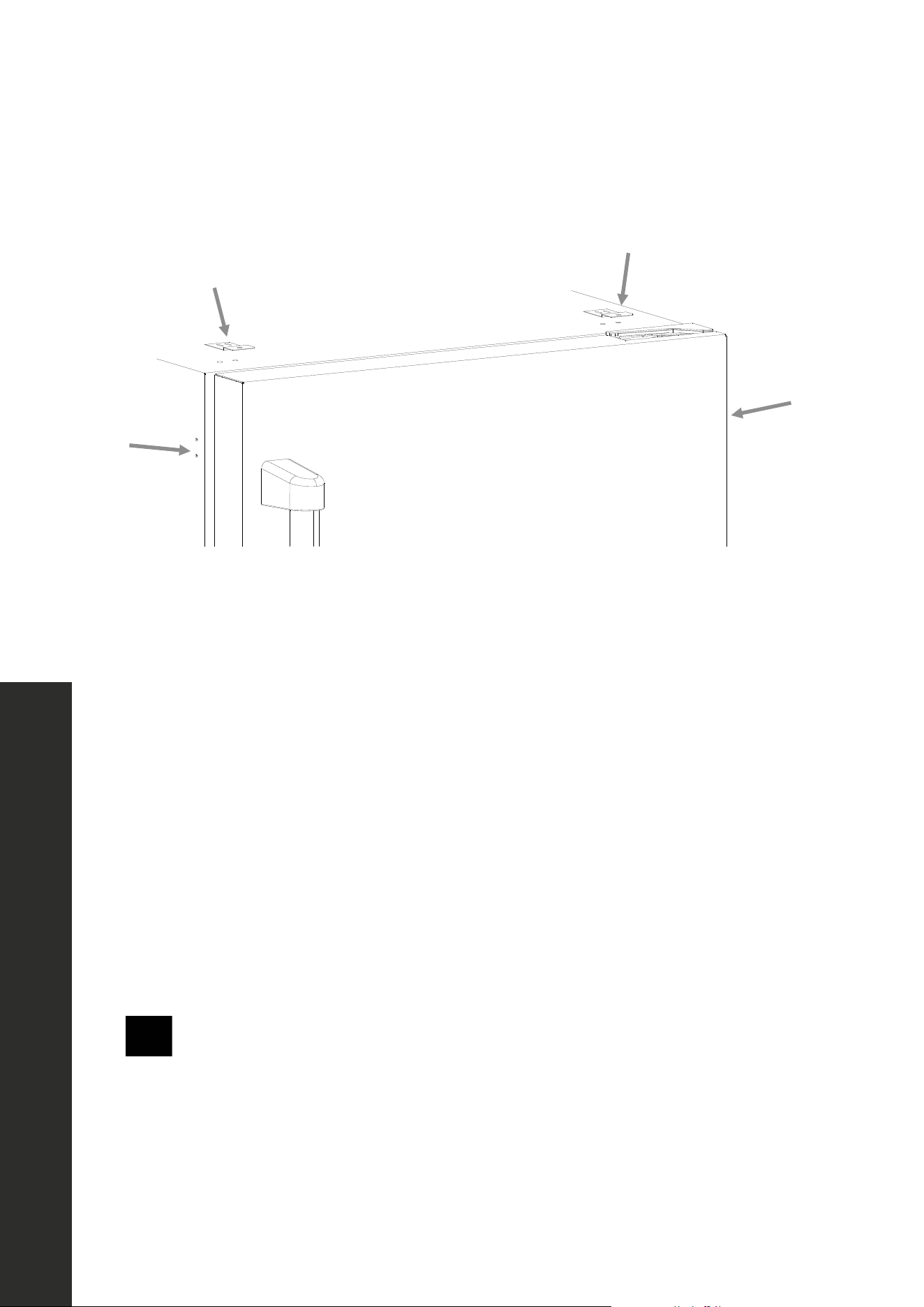
INSTALLING THE ANTI-TIP SYSTEM
1. Once you’ve determined the appropriate height and have ensured the appliance is
level, position the unit at the front of the cutout to install the anti-tip system, which is
necessary to reduce risk of tipping.
2. Using a Phillips-head screwdriver or drill, secure the 2 anti-tip brackets to the top of
the unit using 4 of the provided screws, 2 for each bracket, making sure the lips of the
brackets are facing up and out, as outlined in the image above.
3. Plug the power cord into the wall and push the unit into the cutout, using care to not
tangle or damage the power cord.
4. Once the appliance is in the cutout, secure the anti-tip brackets into the countertop above
using the last 2 screws.
5. If the brackets for the anti-tip system cannot be secured above the appliance and no
wood is available, relocate the brackets for the anti-tip system to the side of the appliance
for securing into an adjacent cabinet, using the same process as above.
WARNING
The anti-tip system must be properly engaged to avoid the unit tipping over and
increasing risk of serious injury or death.
NOTE: The above diagram shows the process on a RBSO-ST-24 model; the anti-tip
system installation process is the same for all models represented in this manual, including
RDSO-ST-24 and RDSPO-24 drawer units.
Anti-Tip System
14
INSTALLATION
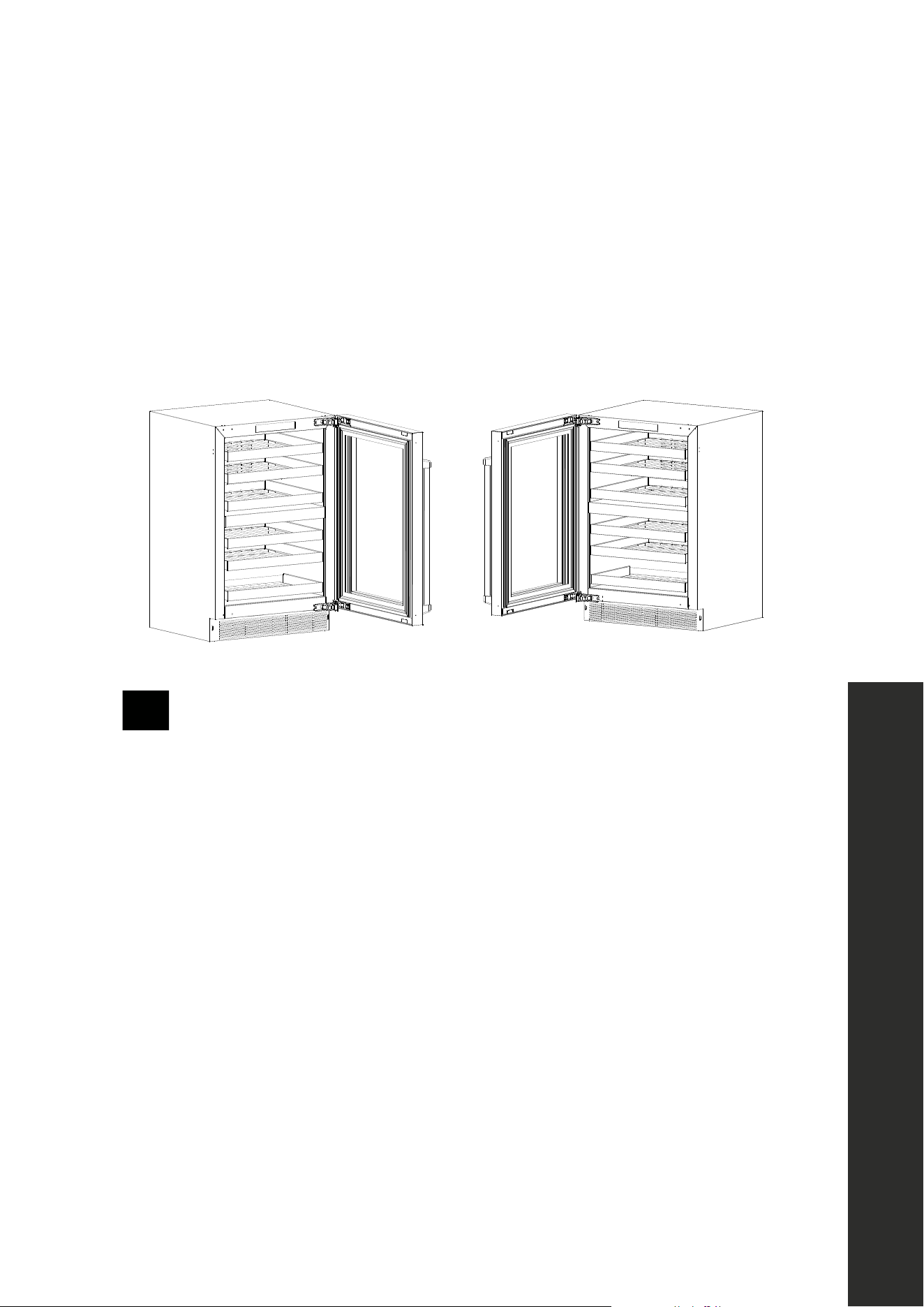
REVERSING THE DOOR SWING
RWDO-GS-24, RWDPO-24, RBSO-GS-24, RBSPO-24, RBSO-ST-24 MODELS ONLY
This appliance has the capability of the doors opening from either the left or right side. The
unit is delivered to you with the doors opening from the left side (Figure 1). Should you desire
to reverse the opening direction (Figure 2), follow the instructions below. NOTE: A second
person is recommended with this task due to the weight of the door.
Figure 1 Figure 2
Make sure the appliance is fully disconnected from power before performing
this task to avoid risk of electric shock.
WARNING
1. With the door open, use a drill or screwdriver to remove the 4 screws at the top and
bottom of the left side of the appliance cabinet face. Save the screws to reinstall once
the door reversal is complete.
2. Loosen the outer top and bottom screws on the right-side hinges. Do not fully remove
these screws to avoid the door falling and creating risk for injury.
3. Next, completely remove the inner top and bottom screws on the right-side hinges.
4. Initially secure the 2 removed screws about 3 turns into the left-side outer top and bottom
screw locations where the screws were removed in step 1.
5. Carefully slide the door from the 2 screw keyholes on the right-side hinges that were not
fully removed in step 2 and lift the door off the hinges.
6. Rotate the door 180° and slide the hinges on the 2 partially installed left-side screws
from step 4.
7. Remove the 2 screws loosened in step 2 from the right-side hinges and install them in the
open inner holes in the left-side hinge location. Tighten all screws.
8. Close the door and check for proper alignment. If needed, loosen the 4 screws enough
to slide the door as needed fine tune the alignment, then re-tighten all 4 screws.
9. Re-secure the 4 screws removed in step into the 4 open holes on the right side.
Reversing the Door Swing
15
Integrated Panel Installation
INSTALLATION
COOLER INTEGRATED DOOR PANEL INSTALLATION
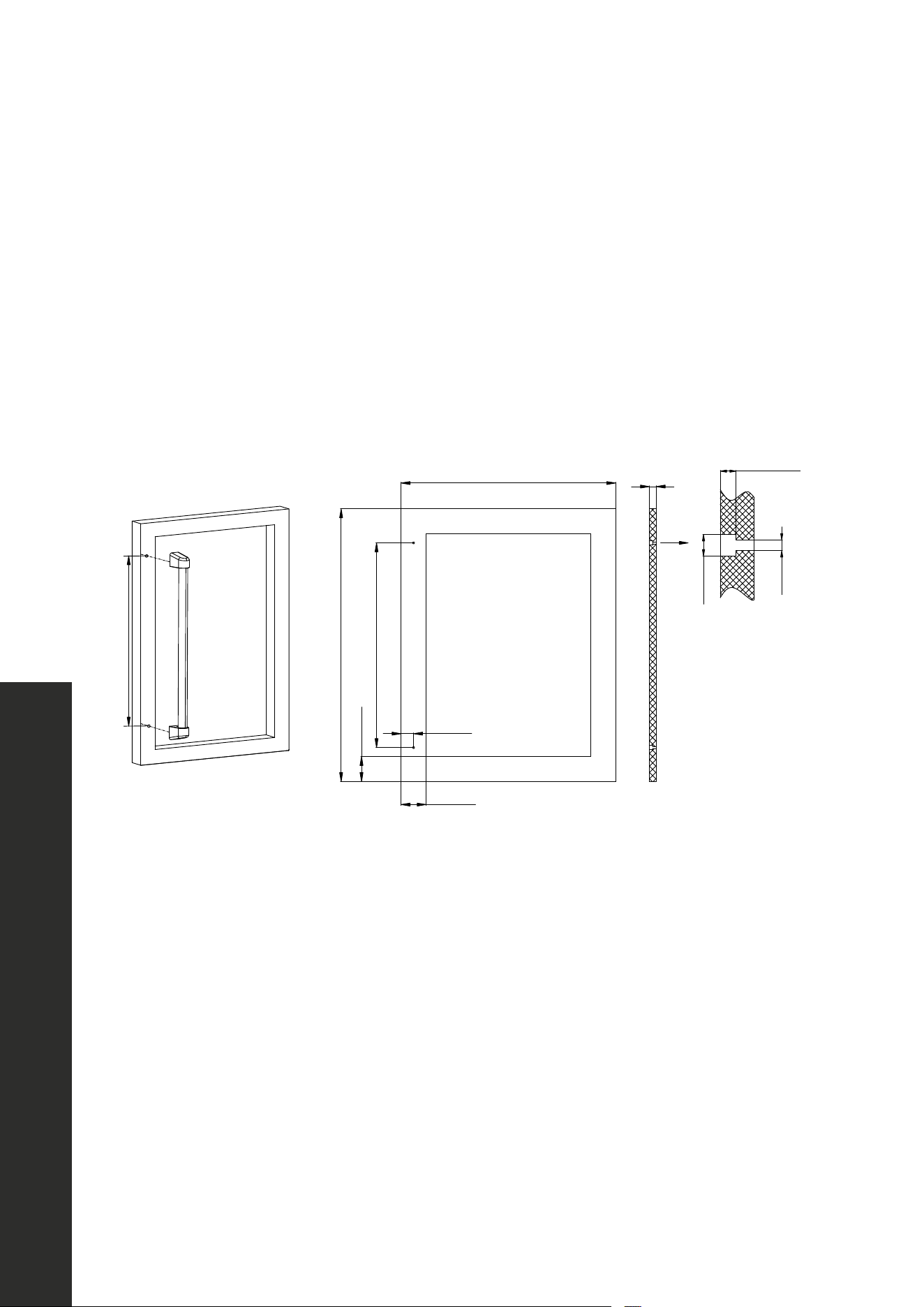
HANDLE INSTALLATION
Prior to installing a custom integrated panel around the glass door on RWDPO-24 and
RBSPO-24 models, handle(s) need to be affixed to the panel first. If you wish to install
a ZLINE Autograph Edition handle onto your custom panel, reference the measurements
displayed in the diagrams below regarding where to affix the mounting studs.
22 1/2" (572 mm)
30" (762 mm)
2 3/4" (70 mm)
22 1/2" (572 mm)
1 3/8" (35 mm)
23 5/8" (600 mm)
3/4"
(20 mm)
Ø1/2" (Ø12 mm)
Ø1/4" (Ø6 mm)
1/4"1/3"
(69 mm)
2 3/4" (70 mm)
16
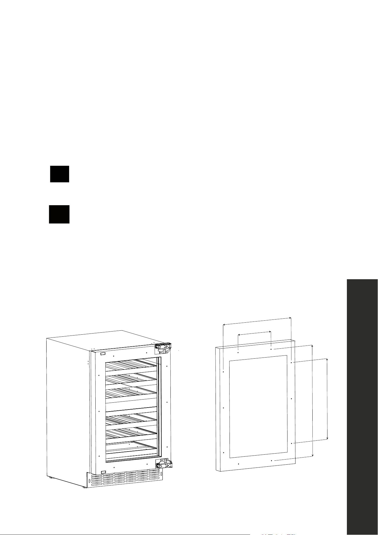
COOLER INTEGRATED DOOR PANEL INSTALLATION
RWDPO-24 and RBSPO-24 models are manufactured without door panels and handles.
To install a custom integrated panel around the glass door, follow the instructions and
dimensions below and on the next page. NOTE: Custom handles need to be affixed to the
panel prior to installing the panel onto the appliance (see page 15). Finish all sides of the
custom panel. They may be visible when the door is open.
WARNING
Make sure the appliance is fully disconnected from power before installing a
door panel to avoid risk of electric shock.
CAUTION
We recommend consulting a professional installer/carpenter when fabricating
a custom panel in wood or another material, as the dimensions provided must
be precisely followed to achieve optimal integration and appliance operation.
PREPARING THE INTEGRATED PANEL
The dimensions in the figure below represent precise distances between the middle of the
corresponding screw holes. When cutting/fabricating the panel, use these measurements so
the screw holes align to ensure a flush installation onto the panel-ready door.
23 5/8" (600 mm)
18 5/8" (472 mm)
Depth of unit behind door:
20 11/16" (526 mm)
Depth of door: 1 3/4" (44 mm)
Recommended depth of
integrated door panel:
3/4" (20 mm)
30"31 "
(762 mm787 mm)
2 3/4" (70 mm)
2 3/4" (70 mm)
Full product height:
34"35"
(864 mm889 mm)
3 3/4"
(95 mm)
30" (762 mm)
6 7/8" (175 mm)
21 1/4" (539 mm)
20 1/2" (520 mm)
27" (685 mm)
INSTALLATION
Integrated Panel Installation
17
INSTALLATION
COOLER INTEGRATED DOOR PANEL INSTALLATION
1. Remove the door from the unit as outlined in the steps on page 14.
2. By hand, remove the rubber door seal to access the panel mounting holes. Set the seal
aside and place the door face side up on a stable surface.
3. Place the panel onto the door and align the top to be flush with the top of the door.
4. Adjust the overlap of the panel — panel width (23 5/8" or 600 mm) is slightly smaller
than the product (23 7/8" or 606 mm) — so it is equal on both sides of the door.
5. Secure the custom door panel to the door using 10 provided wood screws — 3 on each
side and 2 apiece at top and bottom — using a drill or screwdriver, using the precise
measurements provided on page 16.
6. Once installed, replace the door seal by hand. Be sure the seal is properly sealed.
7. Reinstall the door to the unit as outlined in the steps on page 14.
INTEGRATED DOOR PANEL DIMENSIONS
• Reference the dimensions below when fabricating your custom integrated panel.
• Figure 1 is a side view of the unit, showing how the panel (in gray) fits over the panel-
ready door. A panel depth of no more than 3/4" (19 mm) is recommended.
• Figure 2 shows a front view of a custom panel; follow these precise specifications when
cutting/fabricating the panel to perfectly align with the panel-ready door.
23 5/8" (600 mm)
18 5/8" (472 mm)
Depth of unit behind door:
20 11/16" (526 mm)
Depth of door: 1 3/4" (44 mm)
Recommended depth of
integrated door panel:
3/4" (20 mm)
30"31 "
(762 mm787 mm)
2 3/4" (70 mm)
2 3/4" (70 mm)
Full product height:
34"35"
(864 mm889 mm)
3 3/4"
(95 mm)
30" (762 mm)
6 7/8" (175 mm)
21 1/4" (539 mm)
20 1/2" (520 mm)
27" (685 mm)
Figure 1
23 5/8" (600 mm)
18 5/8" (472 mm)
Depth of unit behind door:
20 11/16" (526 mm)
Depth of door: 1 3/4" (44 mm)
Recommended depth of
integrated door panel:
3/4" (20 mm)
30"31 "
(762 mm787 mm)
2 3/4" (70 mm)
2 3/4" (70 mm)
Full product height:
34"35"
(864 mm889 mm)
3 3/4"
(95 mm)
30" (762 mm)
6 7/8" (175 mm)
21 1/4" (539 mm)
20 1/2" (520 mm)
27" (685 mm)
Figure 2
Integrated Panel Installation

18
Integrated Panel Installation
INSTALLATION
COOLER INTEGRATED DOOR PANEL INSTALLATION
DOOR HINGE TIGHTENING
The appliance’s door hinges may loosen over time, which is normal with regular use. Use the
provided Allen key to loosen or tighten screws securing the hinges to the door as necessary,
as outlined in the image below for RWDPO-24 and RBSPO-24 models. For RBSO-GS-24,
RWDO-GS-24, and RBSO-ST-24 models, hinge screws are located behind the rubber
door seal. You can easily remove the upper corners of the seal by hand to access the screws.
19
Integrated Panel Installation
INSTALLATION
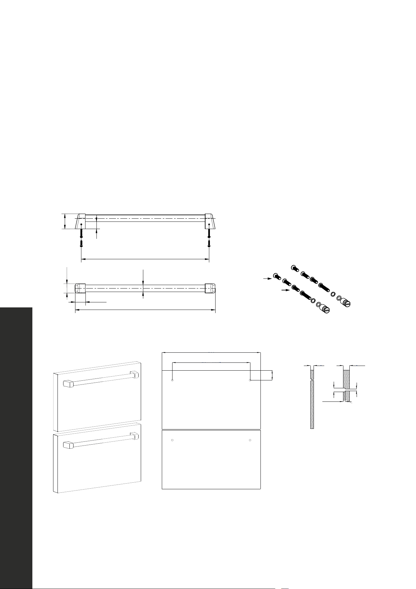
DRAWER INTEGRATED DOOR PANEL INSTALLATION
HANDLE INSTALLATION
Prior to installing a custom integrated panel on the doors of the RDSPO-24 model, handles
need to be affixed to the panel first. If you wish to install a ZLINE Autograph Edition handle
onto your custom panel, reference the measurements displayed in the diagrams below
regarding where to affix the mounting studs.
For Refrigerator Drawer
models, use the included
M5x20 to install the studs.
20 1/2" (520 mm)
1 1/2" (38 mm)
1 3/8" (34 mm)
Ø1" (Ø25 mm)
18 11/16" (474 mm)
2 3/16" (56 mm)
1 1/16" (27 mm)
20 1/2" (520 mm)
1 1/2" (38 mm)
1 3/8" (34 mm)
Ø1" (Ø25 mm)
18 11/16" (474 mm)
2 3/16" (56 mm)
1 1/16" (27 mm)
displayed in the diagrams below regarding where to affix mounting studs.
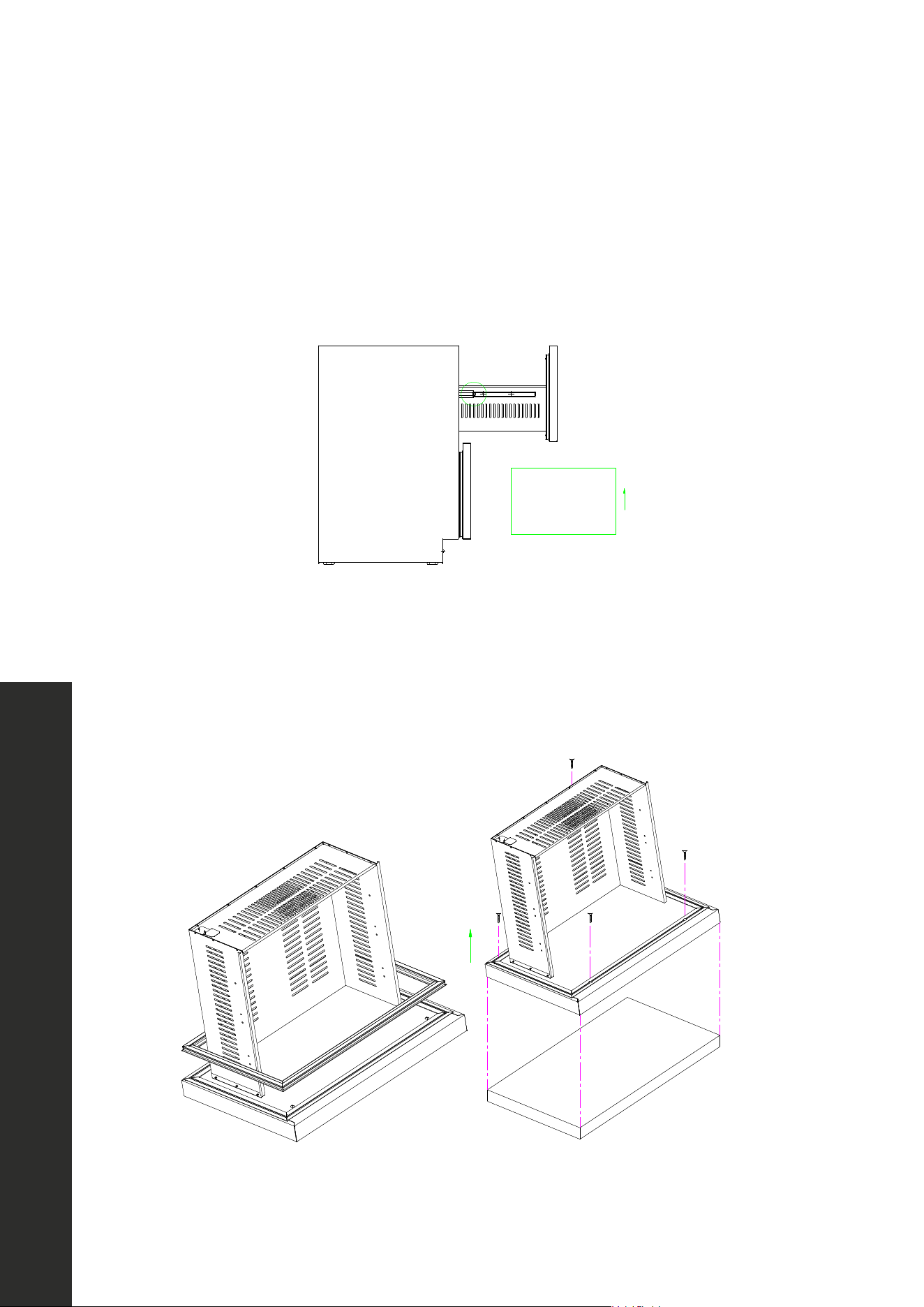
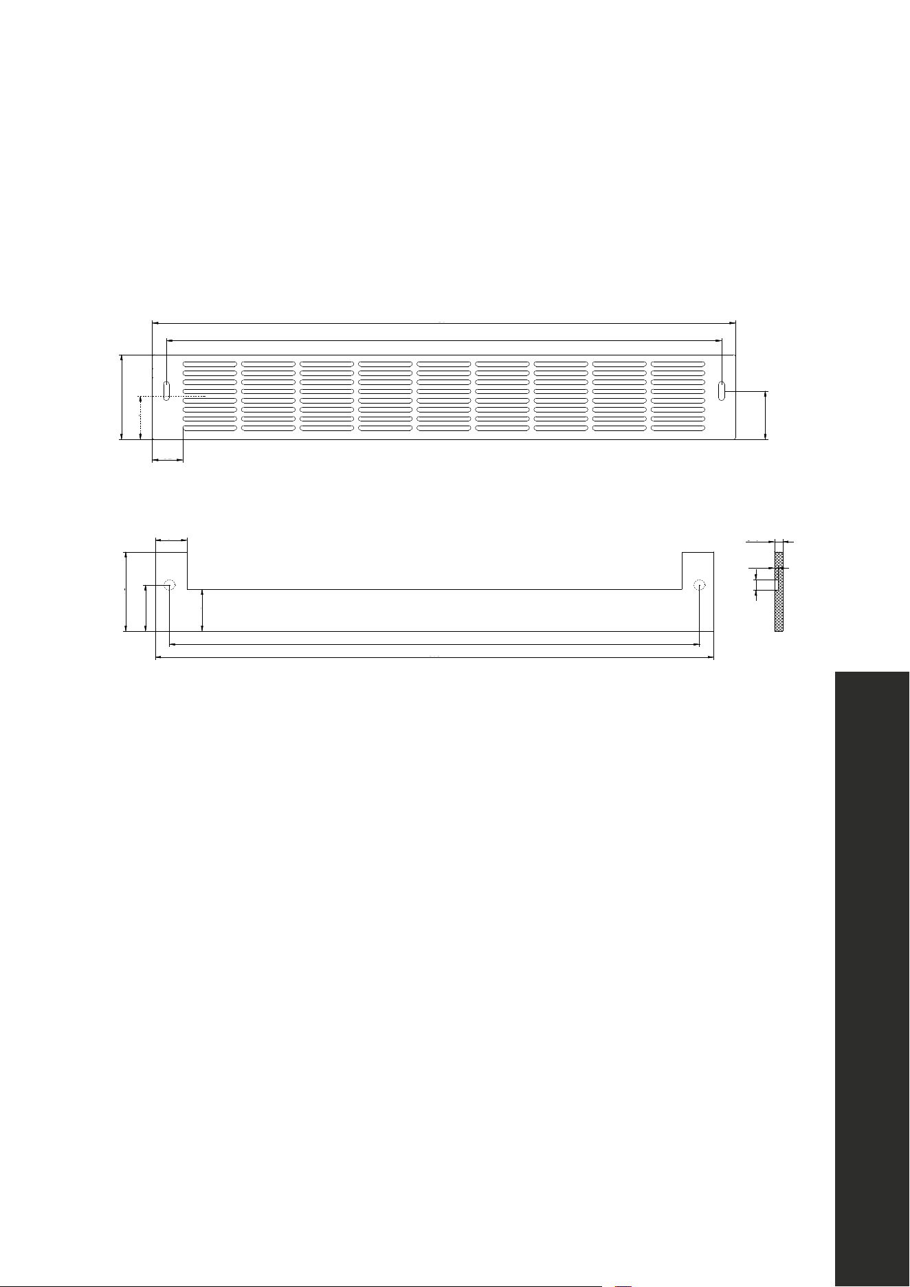
INTEGRATED GRILL/PLINTH
An integrated grill/plinth can be fabricated if desired. The thickness of the panel should be between
1/4 in. to 3/8 in. (6 mm to 9 mm) and the height will vary between 3-5/16 in to 4-5/16 in. (84 mm to
110 mm) depending on you grill grille/plinth height.
Kick plate
NOTE: When finishing the grill/plinth, be sure to stain front, back and all edges to prevent warping.
Apply double-sided tape to the surrounding edges of the integrated grill/plinth as shown in figure.
Remove the backing paper from the double-sided or hook and looptape. Carefully align the grill/plinth
22 5/8" (575 mm)
23 3/4" (604 mm)
23 5/8" (600 mm)
18 11/16" (474 mm)
3 11/16" (93 mm)
1 7/8" (48 mm)
3 9/16" (91 mm)
2 1/16" (53 mm)
1 1/4"
(32 mm)
1 5/16"
(34 mm)
1 7/8"
(48 mm)
2 1/16"
(53 mm)
22 5/8" (575 mm)
23 7/8" (606 mm)
1/4"~3/8"
(6~9 mm)
1/4"~3/16"
(3~4 mm)
1/2"
(12 mm)
2 1/2"
(64 mm)
3/4" (19 mm)
1/4" (6 mm)
1/2" (12 mm)
Ø1/4" (Ø6 mm)
3/4" (19 mm)
20
Integrated Panel Installation
INSTALLATION
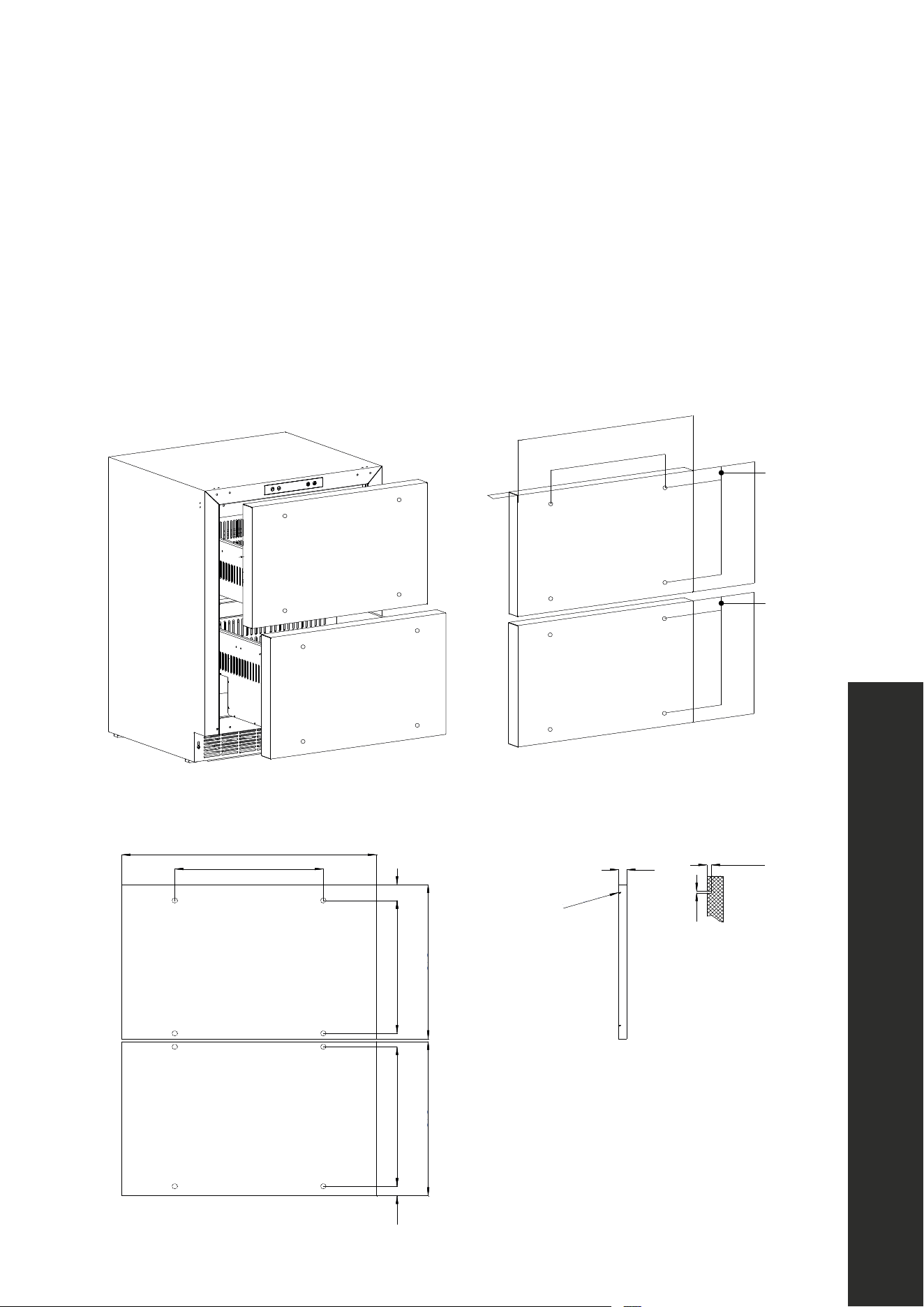
DRAWER INTEGRATED DOOR PANEL INSTALLATION
PREPARING THE PANEL
RDSPO-24 models are manufactured without drawer door panels and handles. The
dimensions in the figure below represent precise distances between the middle of the
corresponding screw holes. When cutting/fabricating the panel, use these measurements
so the screw holes align to ensure a flush installation onto the panel-ready door.
Drawer Refrigerator’s Panel Door Installation
PREPARING THE INTEGRATED PANEL
The dimensions in the figure below represent precise distances between the middle of the
corresponding screw holes. When cutting/fabricating the panel, use these measurements so the screw
holes align to ensure a flush installation onto the panel-ready door.
13 3/4" (350 mm)
1 9/16" (39 mm)
15/16"
(23 mm)
23 5/8" (600 mm)
13 3/4" (350 mm)
23 5/8" (600 mm)
13 3/4" (326 mm)
14 7/8" (378 mm)
13 7/16" (342 mm)
14 7/8" (378 mm)
13 3/4" (326 mm)
3/4"
(19 mm)
3/4" (19 mm)
Ø1/16"
(Ø2 mm)
3/16"-Ø1/16" x 3/16
(4-Ø2x5 mm)
3/16" (5 mm)
14 7/8" (378 mm)
13 7/16" (342 mm)
14 7/8" (378 mm)
1 9/16"
(39 mm)
1/2"
(13 mm)
21
Integrated Panel Installation
INSTALLATION
DRAWER INTEGRATED DOOR PANEL INSTALLATION
DOOR PANEL INSTALLATION
1. Hold the clips on the slider to remove the upper drawer from the unit.
INTEGRATED DOOR PANEL INSTALLATION INSTRUCTIONS
1. Hold the clips on the slider to remove the upper drawer from the unit.
2. Peel off the door gasket from the corner.
3. Adjust the overlap of the custom door panel so it is equal on both sides of the door. Secure the custom door
panel to the door using wood screws. Then recover the door gasket.
4. Repeat the same process to install door panel for the lower drawer.
5. Install both drawers back.
HANDLE INSTALLATION
If you wish to install a ZLINE Autograph Edition handle onto your custom panel, reference the measurements
2. Gently pull the door gasket away from the door starting at the corner
3. Adjust the overlap of the custom door panel so it is equal on both sides of the door. Secure
the custom door panel to the door using wood screws. Then replace the door gasket.
4. Repeat the same process to install door panel for the lower drawer.
5. Install both drawers back.
INTEGRATED DOOR PANEL INSTALLATION INSTRUCTIONS
1. Hold the clips on the slider to remove the upper drawer from the unit.
2. Peel off the door gasket from the corner.
3. Adjust the overlap of the custom door panel so it is equal on both sides of the door. Secure the custom door
panel to the door using wood screws. Then recover the door gasket.
4. Repeat the same process to install door panel for the lower drawer.
5. Install both drawers back.
HANDLE INSTALLATION
If you wish to install a ZLINE Autograph Edition handle onto your custom panel, reference the measurements
22
Integrated Panel Installation
INSTALLATION
DRAWER INTEGRATED DOOR PANEL INSTALLATION
GRILL/PLINTH INSTALLATION
displayed in the diagrams below regarding where to affix mounting studs.
INTEGRATED GRILL/PLINTH
An integrated grill/plinth can be fabricated if desired. The thickness of the panel should be between
1/4 in. to 3/8 in. (6 mm to 9 mm) and the height will vary between 3-5/16 in to 4-5/16 in. (84 mm to
110 mm) depending on you grill grille/plinth height.
Kick plate
NOTE: When finishing the grill/plinth, be sure to stain front, back and all edges to prevent warping.
Apply double-sided tape to the surrounding edges of the integrated grill/plinth as shown in figure.
Remove the backing paper from the double-sided or hook and looptape. Carefully align the grill/plinth
22 5/8" (575 mm)
23 3/4" (604 mm)
23 5/8" (600 mm)
18 11/16" (474 mm)
3 11/16" (93 mm)
1 7/8" (48 mm)
3 9/16" (91 mm)
2 1/16" (53 mm)
1 1/4"
(32 mm)
1 5/16"
(34 mm)
1 7/8"
(48 mm)
2 1/16"
(53 mm)
22 5/8" (575 mm)
23 7/8" (606 mm)
1/4"~3/8"
(6~9 mm)
1/4"~3/16"
(3~4 mm)
1/2"
(12 mm)
2 1/2"
(64 mm)
3/4" (19 mm)
1/4" (6 mm)
1/2" (12 mm)
Ø1/4" (Ø6 mm)
3/4" (19 mm)
NOTE: When finishing the grill/plinth, be sure to stain front, back and all edges to prevent
warping. Apply double-sided tape to the surrounding edges of the integrated grill/plinth
as shown above. Remove the backing paper from the double-sided or hook and looptape.
Carefully align the grill/plinth over the integrated grill/plinth and press into position.

23
Electrical Connection
ELECTRICAL CONNECTION
• For your personal safety, this appliance must be properly grounded. In the event of an
electrical short circuit, grounding reduces the risk of shock by providing an escape wire
for the electric current.
• This appliance is equipped with a cord having a grounding wire and a grounded plug.
The plug must be inserted into an outlet that is properly grounded and installed. For
standard indoor installation, it’s recommended that a dedicated electrical circuit suitable
for a NEMA 5-15 outlet serving only your appliance be used; please ensure the outlet
is easily accessible.
• The ground wire cannot be connected to a gas pipe, heating pipe, water pipe, telephone
line or lightning rod.
• The grounding wire cannot be replaced with the neutral wire of single-phase power.
• In addition to the ground wire, an electrical leakage circuit breaker is also required.
Consult a qualified electrician if you do not completely understand these grounding
instructions.
• Using an outlet with a ground fault circuit interrupter (GFCI) is not recommended.
WARNING
Do not under any circumstances cut or otherwise remove the third (ground)
prong from the power cord. Doing so increases the risk of electric shock, injury,
and/or death.
WARNING
We do not recommend using an extension cord because of potential safety
hazards under certain conditions. If one is used on this appliance, it may void
the warranty.
• For outdoor installation, an electrical leakage circuit breaker is required. Further, if
outdoor installation in a moist or damp location is unavoidable, an electrician must
install a ground fault circuit interrupter (GFCI) electrical outlet.
WARNING
If no GFCI is properly installed, electrical shock, injury, and/or death could
result. Consult a qualified electrician if you do not completely understand these
grounding instructions.
INSTALLATION
24
Buttons and Indicators
OPERATION
PRIOR TO OPERATING THE UNIT
• While this unit is capable of operating in ambient temperatures between 50 °F–110 °F
(10 °C–43 °C), it is recommended you install the appliance in a place where the ambient
temperature is generally between 60 °F–90 F (16 °C–32 °C).
• If the ambient temperature is above or below these recommended temperatures, the
performance of the unit may be affected.
• For example, placing your unit in extreme cold or hot conditions may cause interior
temperatures to fluctuate. This means the desired interior temperature ranges may not be
reached. See more on page 30.
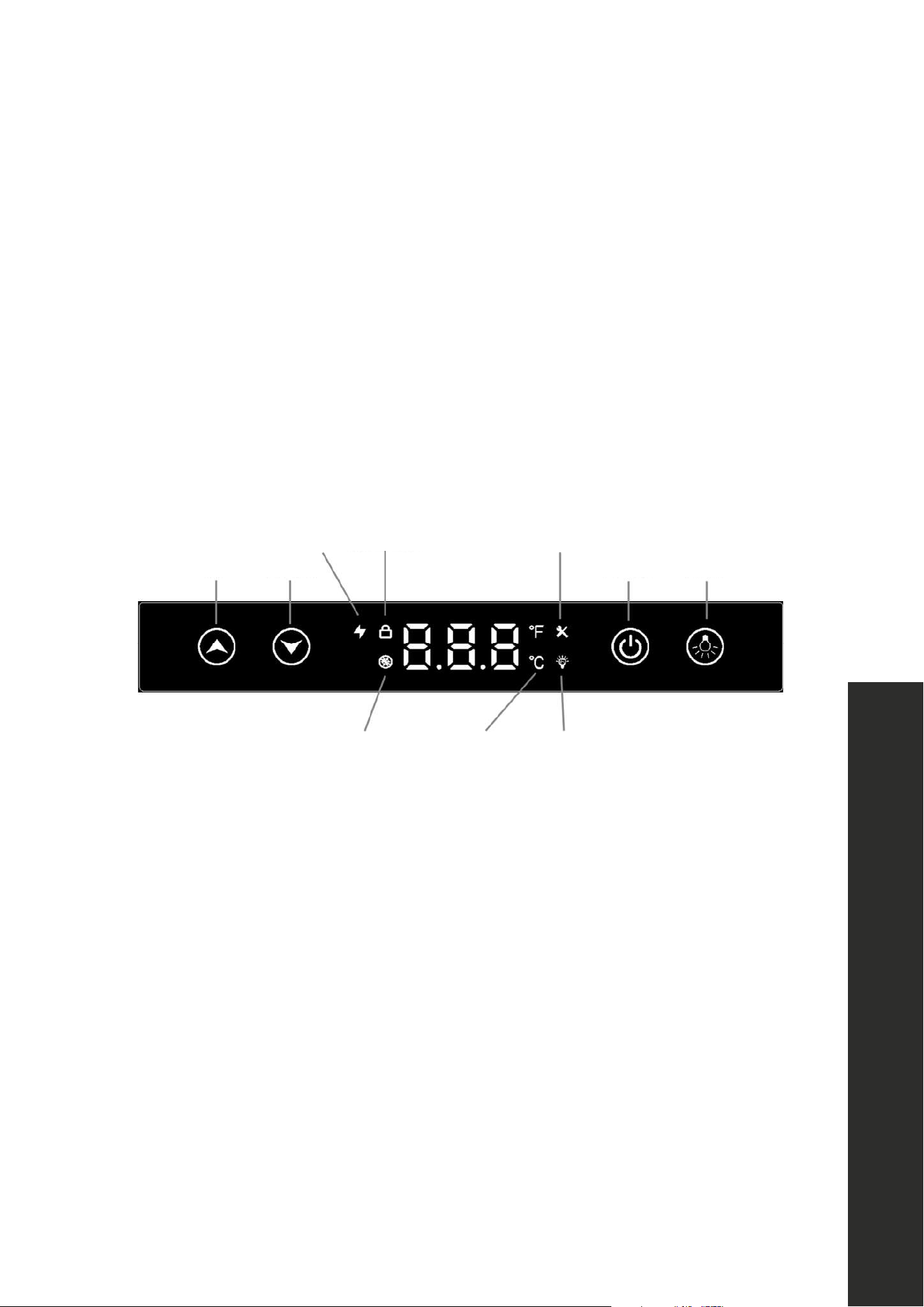
CONTROL PANEL LAYOUT AND OPERATION
Up Down Power Light
Fast cooling Screen lock Maintenance
LightingDefrosting Temp unit
25
Buttons and Indicators
OPERATION
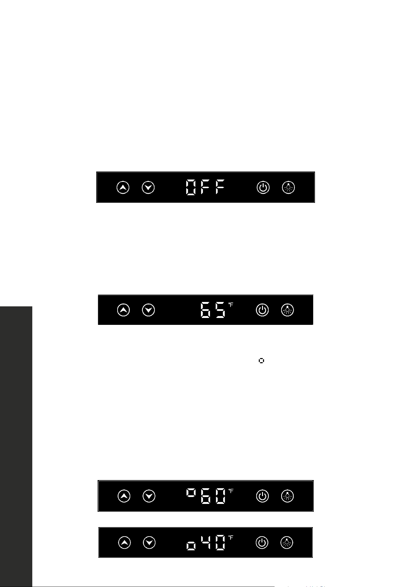
ON/OFF
After plugging in the appliance for the first time, it will be in “stand by” mode, and “OFF”
will display on the screen. Press the “POWER” button once to start the unit. Press and hold
“POWER” for 3 seconds to turn off the unit and return to “stand by” mode. The factory preset
temperature for all models is 38 °F (3 °C), except for wine cooler models. The preset for
wine cooler models is 45 °F (7 °C).
Up Down Power Light
Fast cooling Screen lock Maintenance
LightingDefrosting Temp unit
TEMPERATURE SETTING
Press “UP” or “DOWN” once to start the temperature setting. The current temperature setting
will start flashing. Then press “UP” or “DOWN” to increase or decrease the temperature
setting by 1 °F/ °C intervals. Settings will stop at the minimum and maximum levels once
you reach them. The setting value will auto save after 10 seconds or if the door is closed.
Up Down Power Light
Fast cooling Screen lock Maintenance
LightingDefrosting Temp unit
DUAL ZONE WINE COOLER TEMPERATURE SETTINGS
For models RWDO-GS-24 and RWDPO-24, this symbol
Up Down Power Light
Fast cooling Screen lock Maintenance
LightingDefrosting Temp unit
in front of the temperature
indicates the upper or lower zone temperature. Press “UP” or “DOWN” once to adjust
the temperature setting, then press “LIGHT” to toggle from the upper zone and lower
zone setting.
The default temperature setting for the upper and lower zones are 60 °F and 45 °F
(16 °C and 7 °C). Settings will stop at the minimum and maximum levels once you reach
them. The setting value will auto save after 10 seconds or if the door is closed.
Upper Zone
Lower Zone
26
Buttons and Indicators
OPERATION
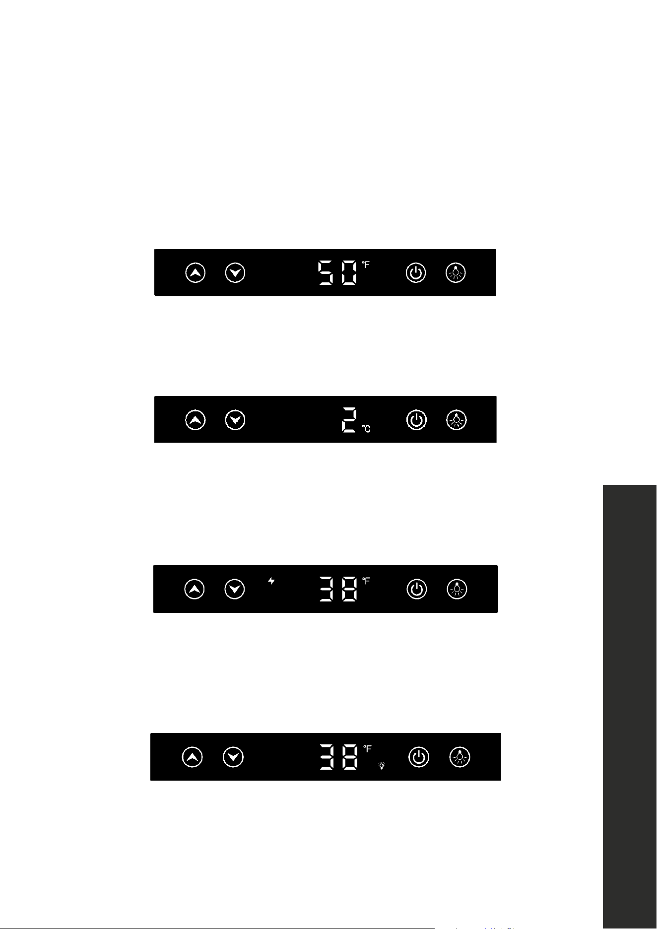
TEMPERATURE DISPLAY SETTING
Press and hold “UP” for 6 seconds to toggle the panel display temperature between the
setting temperature and the real-time temperature of the cabinet interior. The factory preset
temperature display mode is the setting temperature. For faster and more efficient cooling,
close the appliance door after setting the desired temperature.
Upper Zone
Lower Zone
TEMPERATURE UNIT SETTING
Press and hold “UP” and “DOWN” for 3 seconds to toggle the temperature unit to Celsius
or Fahrenheit. Press and hold again to revert.
Upper Zone
Lower Zone
SUPER COOL
Press and hold “UP” and “POWER” for 6 seconds to enter and exit the “super cool” mode,
which will more rapidly chill your appliance. This mode will auto exit after the desired
temperature is reached and the super cool symbol will disappear.
Upper Zone
Lower Zone
LIGHT CONTROL
Press “LIGHT” once to switch the light on/off when the door is open. Press and hold “LIGHT”
for 6 seconds to enter/exit the “light on” mode. In this mode, the light will stay on for 6
hours, with or without door open.
Upper Zone
Lower Zone
27
Buttons and Indicators
OPERATION
ANTI-SWEAT CONTROL (DRAWER MODELS ONLY)
Press and hold “DOWN” and “LIGHT” for 6 seconds to enter anti-sweat control. The anti-
sweat is off by default. Press “UP” or “DOWN” to switch on/off.
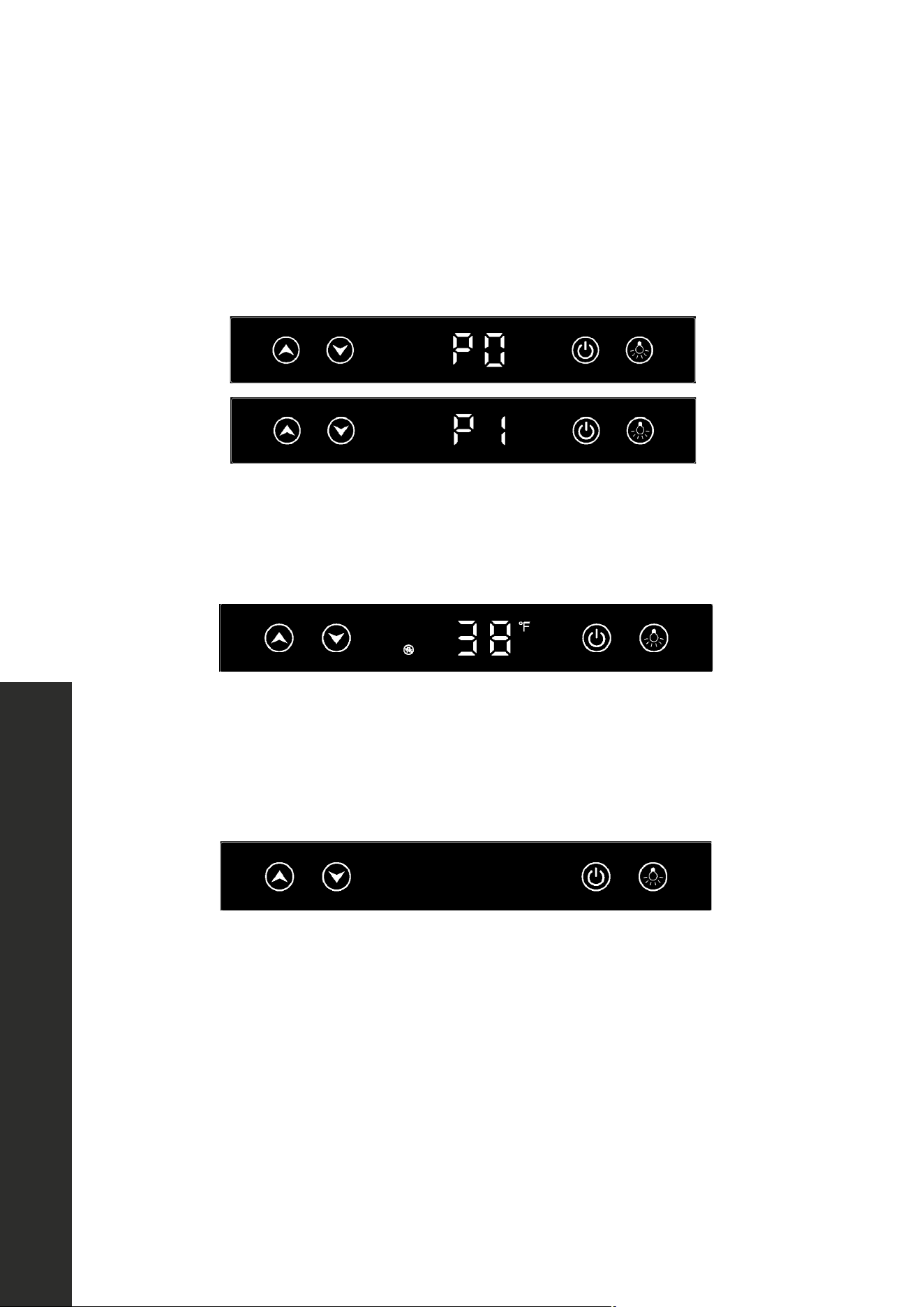
ANTI-SWEAT CONTROL
Press and hold ‘DOWN’ + ‘LIGHT’ for 6 seconds to enter anti-sweat control, the anti-sweat is
default off. press 'UP' or 'DOWN' to switch on/off.
P0 is OFF, P1 is ON. Setting will autosave and exit in 10 seconds.
AUTOMATIC DEFROSTING
Defrosting indicator light up, the compressor will stops for 30 mintunes every 6 hours of system
running.
SABBATH
Press and hold 'UP' + 'LIGHT' over 6 seconds to toggle on/off the sabbath mode.
This mode will shut off the screen display, the operating sounds, and light will be remained off while
the unit still running automaticly according to the previous setting.
SHOWROOM
Press and hold 'DOWN' + 'LIGHT' over 6 seconds to toggle on/off the SHOWROOM mode. The
SHOWROOM indicator will light up.
This mode is for dealers to display the unit, only the light and the evaporator fan will function in this
mode, all alarm will disable except the door open alarm.
SCREEN LOCK
Press and hold 'DOWN' over 6 seconds to lock/unlock the screen, this is to to prevent mis-operating.
is off,
ANTI-SWEAT CONTROL
Press and hold ‘DOWN’ + ‘LIGHT’ for 6 seconds to enter anti-sweat control, the anti-sweat is
default off. press 'UP' or 'DOWN' to switch on/off.
P0 is OFF, P1 is ON. Setting will autosave and exit in 10 seconds.
AUTOMATIC DEFROSTING
Defrosting indicator light up, the compressor will stops for 30 mintunes every 6 hours of system
running.
SABBATH
Press and hold 'UP' + 'LIGHT' over 6 seconds to toggle on/off the sabbath mode.
This mode will shut off the screen display, the operating sounds, and light will be remained off while
the unit still running automaticly according to the previous setting.
SHOWROOM
Press and hold 'DOWN' + 'LIGHT' over 6 seconds to toggle on/off the SHOWROOM mode. The
SHOWROOM indicator will light up.
This mode is for dealers to display the unit, only the light and the evaporator fan will function in this
mode, all alarm will disable except the door open alarm.
SCREEN LOCK
Press and hold 'DOWN' over 6 seconds to lock/unlock the screen, this is to to prevent mis-operating.
is on. Setting
will autosave and exit in 10 seconds.
ANTI-SWEAT CONTROL
Press and hold ‘DOWN’ + ‘LIGHT’ for 6 seconds to enter anti-sweat control, the anti-sweat is
default off. press 'UP' or 'DOWN' to switch on/off.
P0 is OFF, P1 is ON. Setting will autosave and exit in 10 seconds.
AUTOMATIC DEFROSTING
Defrosting indicator light up, the compressor will stops for 30 mintunes every 6 hours of system
running.
SABBATH
Press and hold 'UP' + 'LIGHT' over 6 seconds to toggle on/off the sabbath mode.
This mode will shut off the screen display, the operating sounds, and light will be remained off while
the unit still running automaticly according to the previous setting.
SHOWROOM
Press and hold 'DOWN' + 'LIGHT' over 6 seconds to toggle on/off the SHOWROOM mode. The
SHOWROOM indicator will light up.
This mode is for dealers to display the unit, only the light and the evaporator fan will function in this
mode, all alarm will disable except the door open alarm.
SCREEN LOCK
Press and hold 'DOWN' over 6 seconds to lock/unlock the screen, this is to to prevent mis-operating.
AUTOMATIC DEFROSTING
The automatic defrosting symbol will illuminate, as seen below. During automatic defrosting,
the unit’s compressor stops for 30 minutes for every 6 hours of the system running.
SABBATH MODE
Press and hold “UP” and “LIGHT” for 6 seconds to toggle on/off “Sabbath mode.” This mode
will shut off the screen display, operating sounds, and light while the unit still runs automatically
according to the previous temperature setting.
28
Buttons and Indicators
OPERATION
SHOWROOM MODE
To enable this function, first hold the power button for 3 seconds to enter standby mode.
When the display shows “OFF”, press and hold “DOWN” and “LIGHT” for 6 seconds
to toggle on/off the showroom mode. This functional can only be turned on/off when in
standby mode. The showroom indicator will light up. This mode is for dealers to display the
unit. Only the light and the evaporator fan will function in this mode. All alarms are disabled
except for the door open alarm.
ANTI-SWEAT CONTROL
Press and hold ‘DOWN’ + ‘LIGHT’ for 6 seconds to enter anti-sweat control, the anti-sweat is
default off. press 'UP' or 'DOWN' to switch on/off.
P0 is OFF, P1 is ON. Setting will autosave and exit in 10 seconds.
AUTOMATIC DEFROSTING
Defrosting indicator light up, the compressor will stops for 30 mintunes every 6 hours of system
running.
SABBATH
Press and hold 'UP' + 'LIGHT' over 6 seconds to toggle on/off the sabbath mode.
This mode will shut off the screen display, the operating sounds, and light will be remained off while
the unit still running automaticly according to the previous setting.
SHOWROOM
Press and hold 'DOWN' + 'LIGHT' over 6 seconds to toggle on/off the SHOWROOM mode. The
SHOWROOM indicator will light up.
This mode is for dealers to display the unit, only the light and the evaporator fan will function in this
mode, all alarm will disable except the door open alarm.
SCREEN LOCK
Press and hold 'DOWN' over 6 seconds to lock/unlock the screen, this is to to prevent mis-operating.
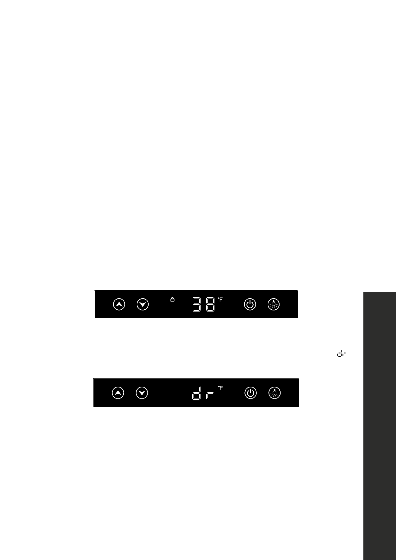
SCREEN LOCK
Press and hold “POWER” and “LIGHT” for over 6 seconds to lock/unlock the screen to
prevent children or others from operating the appliance. When locked, the symbol below
will illuminate.
DOOR OPEN ALARM
If the door has been left open for more than 5 minutes, the alarm will sound along with
flashing in the display. The alarm will stop by closing the door or press any key.
29
OPERATION
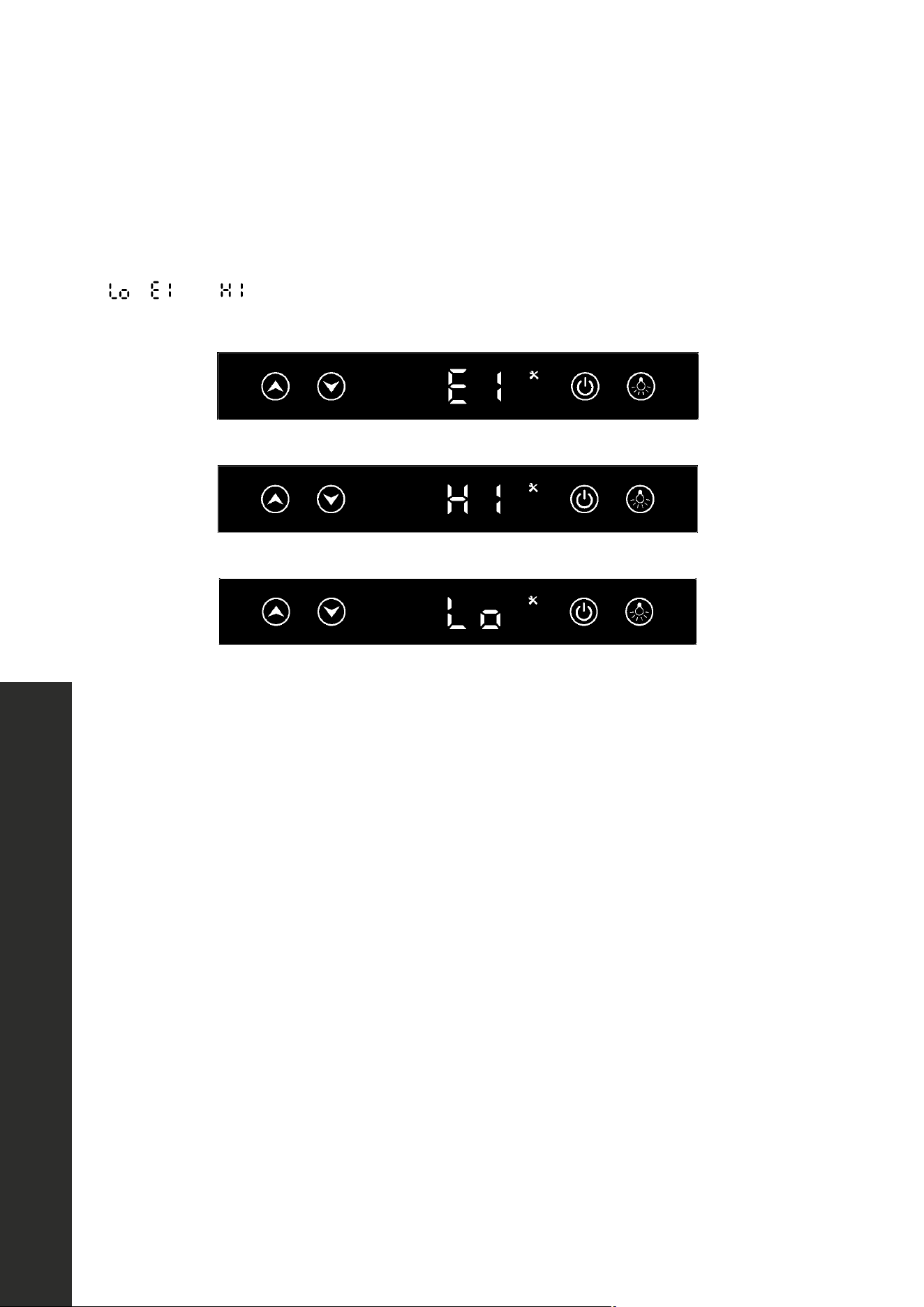
ERROR ALARMS
This refrigerator has built-in alarm system feature that activates when the unit detects any
malfunction in the sealed cooling system. If the temperature display window displays
, , or , and the “ALARM” indicator begins flashing, please proceed to
"Troubleshooting" on page 33.
WINE STORAGE TEMPERATURES
• While certain wines store best at temperatures between 56 °F–58 °F (13 °C–14 °C),
your unit also allows you to store wine at drinking temperatures.
• Generally, red wine should be kept at 60 °F–61 °F (16 °C) and white wine, which is
usually served chilled, is best kept at 54 °F –55 °F (12 °C).
• Sparkling wines should be kept at about 46° F (8 °C). For beer and soft drinks, choose
the temperature setting that is most agreeable to you and your guests.
Error Alarms

30
Energy-Saving Tips
OPERATION
ENERGY-SAVING TIPS AND OTHER NOTES
• Do not place the unit next to a heating vent, a range/oven, or in direct sunlight.
• Keep the door closed as much as possible, especially in hot, humid weather.
• Cover foods and beverages to reduce moisture buildup inside the appliance.
• A temperature sensor records the average temperature of the unit. Since cold air falls
and warm air rises, there will be a temperature variation from the bottom to the top of the
unit, meaning the bottom of the unit will always be slightly colder,
• The control panel controls the average temperature of the unit. The temperature displayed
on the control panel is the instantaneous average temperature of the unit; as such,
variations of anywhere from 1 to 6 degrees is normal.
• When fully loaded with room temperature product, the unit will operate continuously for
as long as 24 hours to reduce the temperature inside the cabinet to the desired point.
Under normal conditions, when the unit has been on for 6 hours, it will stop working for
about 30 minutes to defrost automatically.
CAUTION
Damages caused by ambient temperatures of 40 °F (4 °C) or below are not
covered by the warranty. To temporarily stop cooling, unplug the unit. To shut
down for longer periods, disconnect and leave the door partially open.
• While this unit is designed to operate between 50 °F and 110 °F (10 °C and 43 °C),
higher ambient temperatures may reduce the unit’s ability to reach low temperatures.
• Optimal results are obtained at temperatures between 65 °F and 80 °F (18 °C and
27 °C) for built-in models and between 65 °F and 90 °F (18 °C and 32 °C) for
freestanding models.
NOTE: If you unplug the refrigerator, allow at least 3 minutes before plugging it back in. The
unit may not restart in less than 3 minutes.
• The refrigerator section of the unit comes with a removable divider to help organize
groceries.
• To unlock the divider, turn the knob on top counterclockwise.
• Using the same knob, adjust the divider left to right and/or top to bottom to create
sections within the unit.
• To lock the divider, turn the knob on top clockwise.

31
WARNING
Make sure the appliance is fully disconnected from power before performing
any cleaning or maintenance to avoid risk of electric shock or injury.
NOTE: Periodic cleaning and proper maintenance will ensure efficiency, top performance,
and long life of the appliance.
CLEANING THE EXTERIOR
Clean the exterior stainless steel with a cloth dampened in mild soapy water. After cleaning,
dry thoroughly with a soft cloth and polish with a stainless steel cleaner. To clean the door
or drawer gasket, use only mild soapy water. Never use harsh cleansers or scouring pads
to clean any part of your unit.
CLEANING THE INSIDE
Remove any contents inside the refrigerator. Rinse the inside surfaces with plain water and
thoroughly dry the interior, including stainless steel racks and glass shelving. Avoid getting
excess water inside the machine since it will flow into the water trap near the compressor
and possibly overflow.
DEFROSTING THE UNIT
The unit uses an automatic defrost system in which the refrigerated surfaces of the unit defrost
automatically. Defrost water drains into a hole in the floor of the storage compartment and
is channeled into a drain pan located at the back of the unit near the compressor. Heat
transferred from the compressor evaporates any water that has collected in the pan. Be sure
the drain hole in the floor of the unit is clear and unobstructed.
START-UP AFTER LONG-TERM STORAGE
1. If stored outside, it is recommended that the unit again be thoroughly inspected per
the storage instructions above to address any dirt or debris from the weather and/or
animals/insects.
2. Once fully cleaned, connect the unit to electrical power.
3. Turn unit on and confirm your desired control settings.
4. Allow 24 hours for the unit to stabilize before loading contents.
CARE AND MAINTENANCE
Care and Maintenance

32
WINTERIZING YOUR UNIT
If an outdoor refrigerator will be exposed to temperatures of 40 °F (4 °C) or less, perform
the following steps to winterize the unit so it will keep it in good condition while facing the
winter elements. It is important to clean and dry this appliance to prevent severe mold and
mildew growth from engulfing the fridge’s interior.
1. Turn the unit OFF by pressing the POWER button on the control panel.
2. Remove all food and drink contents from the refrigerator.
3. Unplug the unit from the power outlet. It is also recommended that the power to the outlet
be turned-off if the circuit is not required for other appliances.
4. Place all cords in a small bag or tie them together with a plastic zip-tie.
5. If necessary, move the unit so you can gain access to the rear of the product.
6. Remove the front toe kick at the bottom of the unit by removing 2 Phillips-head screws on
each side. Then, use a brush and vacuum to clean dirt and debris from beneath the unit.
Thoroughly clean the toe kick and re-install on the unit.
7. Remove the screws securing the rear access cover and use a brush and vacuum to clean
dirt and debris from the machine compartment.
8. Check if the plastic defrost drain pan located near the compressor contains water; use a
sponge to remove as much water as possible.
9. Thoroughly clean the rear access cover and re-install on the unit.
10. Clean the exterior and interior of refrigerator thoroughly. Wipe down and dry the
refrigerator with cloths or paper towels after it has been cleaned. Ensure all water has
been removed from the unit.
11 . Leave the refrigerator door or drawers open to prevent formation of mold and mildew.
Open the door a minimum of 2" (51 mm) to provide the necessary ventilation.
12. It’s recommended to not cover up the unit during winterization, as this may trap
condensation. If you are concerned about exposure to the elements, use a synthetic
cover that will not hold moisture to protect the appliance, though the door should remain
open as much as possible.
13. After completion of the above, you may choose to store the unit indoors, although this is
not required.
CARE AND MAINTENANCE
Care and Maintenance
33
TROUBLESHOOTING
ISSUE POSSIBLE SOLUTION
Unit does not turn on
Not plugged in.
Fuse blown or circuit breaker tripped.
Press power button on control panel.
Noise or vibration Check that unit is level. If not, adjust leveling legs.
Unit is too warm
Check that door is properly closed and sealed.
Check temperature setting. To change the temperature
setting, follow the steps in "Control Panel Layout And
Operation" on page 24 of this manual.
Check if door has been opened frequently or recently filled
with product.
Unit develops
condensation on
external surfaces
Check that the unit is properly exposed to excessive
humidity. Moisture will dissipate as humidity levels decrease.
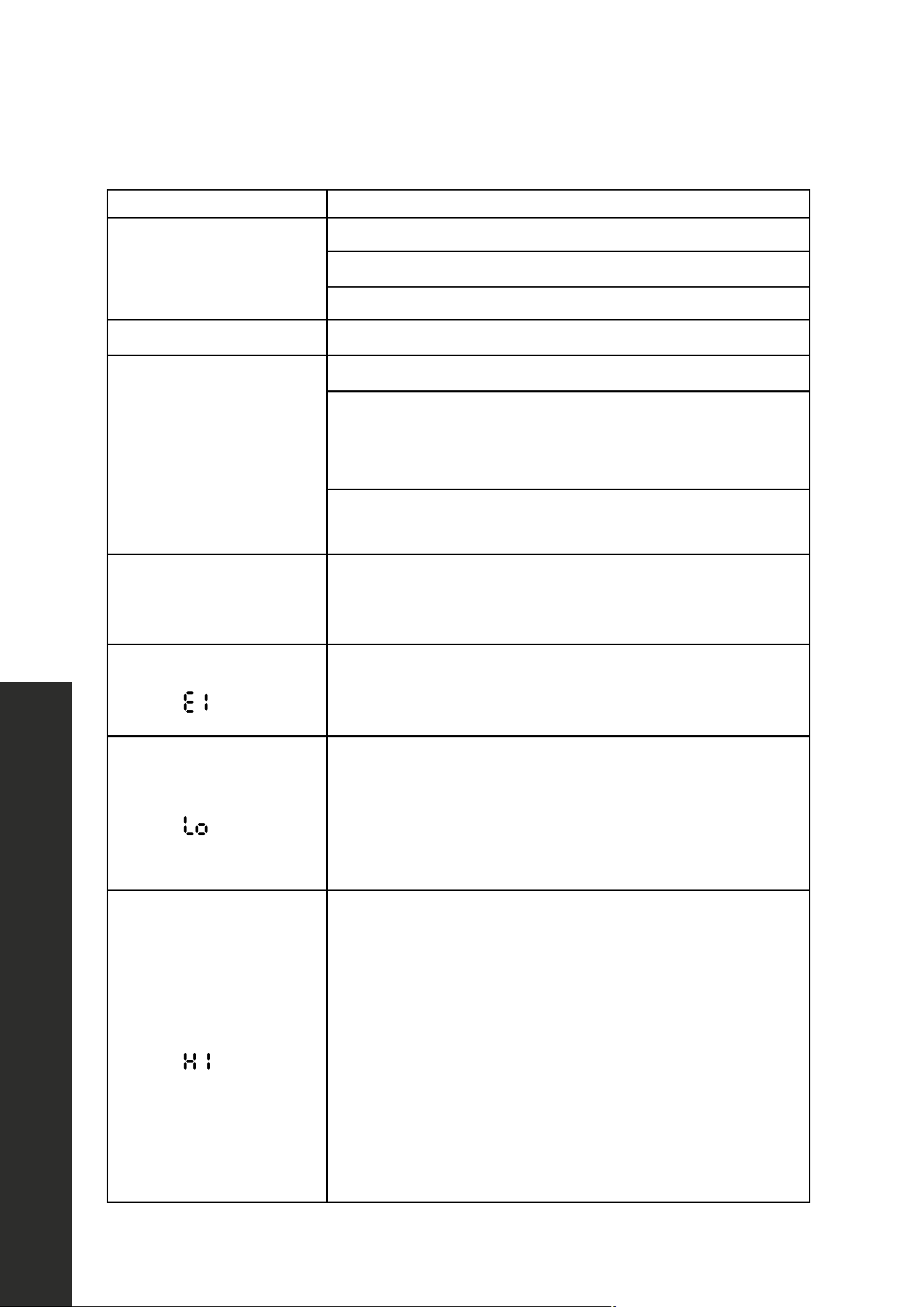
Temperature window
displays
This error code indicates the thermostatic sensor has
malfunctioned. Contact ZLINE Customer Service at
1-614-777-5004 for assistance.
Temperature window
displays
This error code indicates the actual temperature is much
lower than your set temperature. Try restarting. Unplug
the unit and wait at least 3 minutes before plugging back
in. If the problem isn’t fixed, contact 1-614-777-5004 for
assistance.
Temperature window
displays
This error code indicates the actual temperature is much
higher than your set temperature. Possible causes are:
• The door might not be fully closed.
• The refrigerant may have leaked.
• The unit may have been recently loaded with room
temperature product.
• The control panel may not be functioning properly and
should be replaced.
If you are certain the door is not the cause of the problem,
contact 1-614-777-5004 for assistance.
Troubleshooting

WARRANTY
COVERAGE
ZLINE Kitchen and Bath ("ZLINE") wine coolers and beverage refrigerators have a two year
parts and service warranty and a five year parts warranty on the unit's sealed cooling system.
ZLINE warranty periods begin from the original date of product delivery and solely cover
the original purchaser of the product, delivered new and in its original carton. The limited
warranty covers all parts and labor for necessary repairs if any part of the product, or the
product itself, proves to be defective in materials or workmanship.
The product must be deemed serviceable via troubleshooting with the ZLINE Customer
Experience team. All service on ZLINE products under warranty must be performed by
ZLINE-approved and ZLINE-certified service providers unless otherwise specified by ZLINE.
Service will be provided during normal business hours.
Products must be unobstructed and accessible to the service provider at the time of service.
ZLINE’s liability is limited to the original purchase price of the product. Additional injuries,
losses, damages, or other inconveniences caused by product malfunction or defects in
materials are not covered under the terms of this warranty.
TERMS
ZLINE warranties apply only to the original purchaser of a ZLINE product installed for normal
residential use. This is defined as a single-family, residential dwelling in a non-commercial
setting. Any warranty claim stemming from installation, operation, or any other use within a
commercial setting is not covered under this limited warranty. Commercial settings include,
but are not limited to: schools, churches, hotels, restaurants, vacation rentals such as Airbnb,
daycare centers, private clubs, fire stations, common areas in multi-family dwellings, nursing
homes, food service locations, and institutional food service locations such as hospitals or
correctional facilities.
This warranty is non-transferable and will not under any circumstance be extended based
on the date of installation — the warranty period takes effect from the date of delivery and
only covers the original purchaser. The warranty applies only to products installed in the
contiguous United States and the District of Columbia.

WARRANTY
Failure to secure certified warranty service per these terms will result in a forfeiture of the
remaining warranty. Out-of-pocket payments will not be reimbursed unless prior approval
is received from ZLINE and/or ZLINE-certified service contract partners. Unapproved out-
of-pocket payments for service will not be reimbursed. All warranty procedures must be
followed to maintain warranty coverage.
If a product qualifies within the service window provided under these warranty terms, and
ZLINE is unable to repair the product or a defective part of the product after a reasonable
number of attempts, ZLINE reserves the right to offer to replace the defective part or the
product or provide the original purchaser a full refund of the purchase price of the product
(not including installation, removal, or other charges that were not included in the original
purchase price).
The original purchaser of the product must provide the original proof of purchase, including
the purchase date, when filing a claim to obtain replacement parts, service, or refunds.
Additionally, the original purchaser of the product must provide the serial number of the
product when filing a claim to obtain replacement parts, service, or refunds.
This warranty shall not apply to any ZLINE product in which the original factory serial
number has been removed, altered, or cannot be readily determined for any reason. Further,
ZLINE is not responsible for damage resulting from, but not limited to: shipment, delivery, or
improper installation; negligence or improper maintenance, misuse, or abuse of the product;
unauthorized alteration, modification, or tampering with the product; accident, fire, floods,
pest infestations, pandemics, natural disasters, or any other unpreventable or unexplained
acts of nature, commonly referred to as “acts of God”; flare-up fires or damages caused
by improper electric supply, electrical line current, voltage, or power surges; and service
to correct installation not in accordance with the instructions contained in ZLINE’s product
manuals and/or with local government codes.
In the event service is dispatched, and it is discovered that the reported issue is not covered
under warranty based on the disclaimers above, the customer will be responsible for all service
fees. Failure to pay these fees will result in the forfeiture of remaining warranty coverage.

WARRANTY
Information contained within ZLINE’s installation and user manuals, in addition to product
information included on ZLINE’s website and all related digital listings, do not cover every
possible condition and situation that may occur during the installation or operation of
ZLINE products.
ZLINE reserves the right to make changes at any time to its products when considered safe,
necessary, and useful. Always check the ZLINE website for the most up-to-date version of its
product manuals: www.zlinekitchen.com/pages/manuals.
Do not install or operate any ZLINE product if it has missing or broken parts or if it arrives
damaged due to shipping. If ZLINE products arrive damaged, contact ZLINE Customer
Experience at 1-614-777-5004 for help. Failure to report a damaged appliance prior to
installation or operation may void the warranty.
ZLINE disclaims responsibility for damage or injury caused by improper installation or
use of any of its products. ZLINE is under no obligation, by law or otherwise, to provide
concessions, including repairs, prorates, rebates, discounts, or replacements, once the
warranty has expired.
SERIAL NUMBER LOCATION
Please write down the model number and serial number
of your appliance. The model number and serial
number are located on the rating label on the back of
your unit. In some models, the serial number may also
be located on the top center of the interior on your
appliance. See example of an RWDPO-24 to the left;
label locations are similar across all Touchstone
models. Both numbers are needed to obtain warranty
service. Do not remove permanently affixed labels,
warnings, or plates from the product. This will void the
warranty. You may also consider attaching your receipt
or proof of purchase to this manual.

WARRANTY
SERVICE
For warranty service, please contact our Customer Service team
at 1-614-777-5004 or visit www.zlinekitchen.com/contact to
utilize our online Customer Experience Portal.
Scan the QR code to view the most up-to-date version of our
Installation Manual and User Manual.
Need to purchase a part or accessory for your ZLINE
product? Visit www.zlineparts.com, ZLINE’s official parts
distribution partner.