www.peavey.com
PV
®
5300
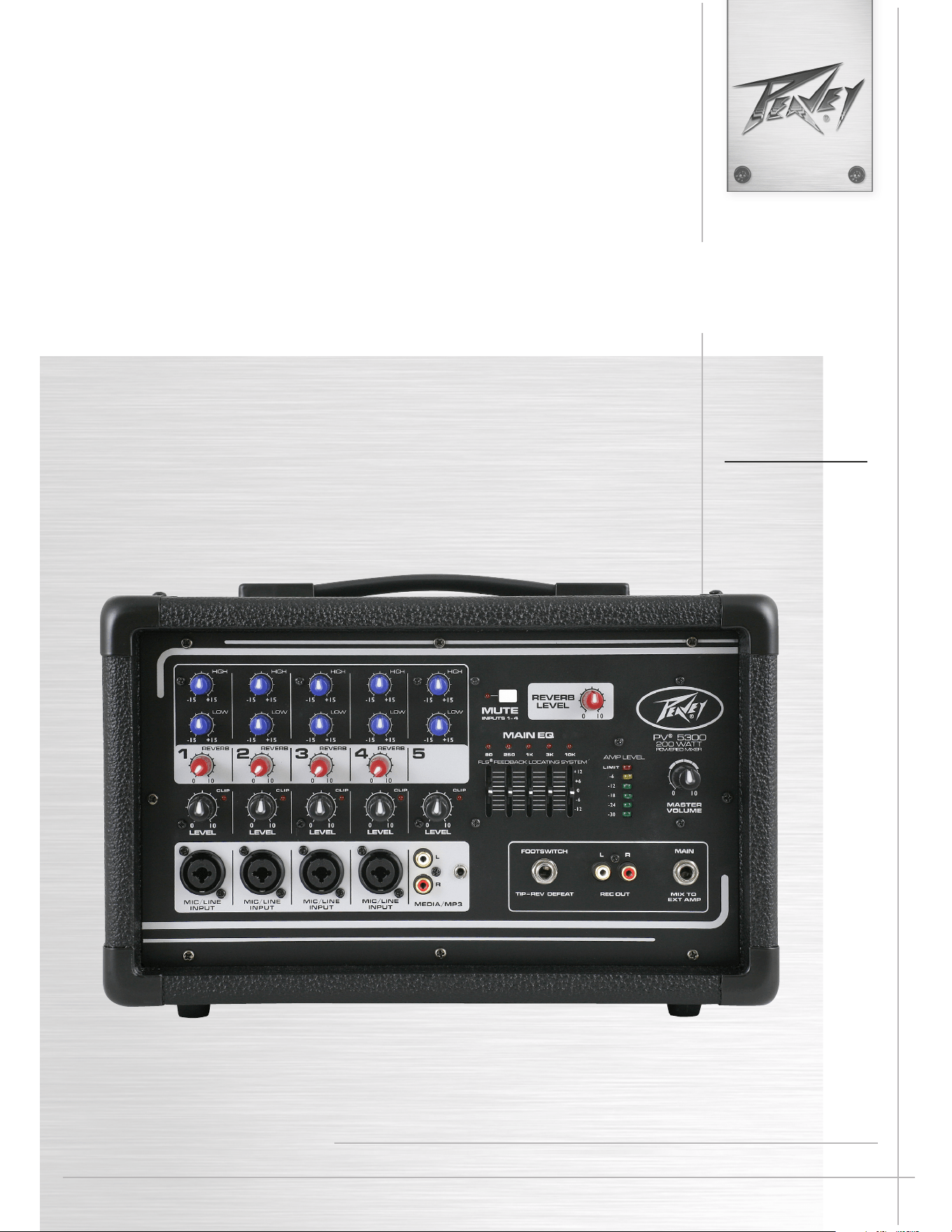
200-Watt, 5-Channel Mixer aMPlifier
Operating
Manual
Intended to alert the user to the presence of uninsulated “dangerous voltage” within the product’s enclosure that may be of sufcient magnitude to constitute
a risk of electric shock to persons.
Intended to alert the user of the presence of important operating and maintenance (servicing) instructions in the literature accompanying the product.
CAUTION: Risk of electrical shock — DO NOT OPEN!
CAUTION: To reduce the risk of electric shock, do not remove cover. No user serviceable parts inside. Refer servicing to qualied service personnel.
WARNING: To prevent electrical shock or re hazard, this apparatus should not be exposed to rain or moisture‚ and objects lled with liquids‚ such as vases‚
should not be placed on this apparatus. Before using this apparatus‚ read the operating guide for further warnings.
Protective earthing terminal. The apparatus should be connected to a mains socket outlet with a protective earthing connection.
SPANISHENGLISH
FINNISH
FRENCH
SWEDISH
GERMAN
Tarkoitettu kiinnittämään käyttäjän huomio sellaiseen eristämättömään vaaralliseen jännitteeseen tuotteen kotelossa, joka saattaa olla riittävän suuri
aiheuttaakseen sähköiskuvaaran.
Tarkoitettu kiinnittämään käyttäjän huomio tärkeisiin käyttö- ja huolto-ohjeisiin tuotteen mukana seuraavassa ohjeistuksessa.
VAROITUS: Sähköiskun vaara — ÄLÄ AVAA!
VAROITUS: Sähköiskuvaaran vuoksi älä poista kantta. Ei sisällä käyttäjän huollettavissa olevia osia. Huoltaminen tulee jättää pätevän huoltohenkilöstön
tehtäväksi.
VAARA: Sähköiskun tai tulipalon vaaran estämiseksi tätä laitetta ei saa altistaa sateelle tai kosteudelle, eikä sen päälle saa asettaa nesteellä täytettyjä
esineitä, kuten maljakoita. Ennen laitteen käyttöä lue muut varoitukset käyttöohjeesta.
Suojamaadoitus terminaali. Laite tulee kytkeä sähköverkkoon suojajohtimella.
Ce symbole est utilisé dans ce manuel pour indiquer à l’utilisateur la présence d’une tension dangereuse pouvant être d’amplitude sufsante pour constituer
un risque de choc électrique.
Ce symbole est utilisé dans ce manuel pour indiquer à l’utilisateur qu’il ou qu’elle trouvera d’importantes instructions concernant l’utilisation et l’entretien de
l’appareil dans le paragraphe signalé.
ATTENTION: Risques de choc électrique — NE PAS OUVRIR!
ATTENTION: An de réduire le risque de choc électrique, ne pas enlever le couvercle. Il ne se trouve à l’intérieur aucune pièce pouvant être reparée par
l’utilisateur. Conez I’entretien et la réparation de l’appareil à un réparateur Peavey agréé.
AVIS: Dans le but de reduire les risques d’incendie ou de decharge electrique, cet appareil ne doit pas etre expose a la pluie ou a l’humidite et aucun objet
rempli de liquide, tel qu’un vase, ne doit etre pose sur celui-ci. Avant d’utiliser de cet appareil, lisez attentivement le guide fonctionnant pour avertissements
supplémentaires.
Borne de terre de protection. L'appareil doit être connecté à une prise secteur avec une connexion à la terre.
Är avsedd att varna användaren för förekomsten av oisolerad ”farlig spänning” inom produktens hölje som kan vara av tillräcklig nivå för att personer ska
riskera elektrisk stöt.
Är avsedd att uppmärksamma användaren på förekomsten av viktiga handhavande- och underhållsinstruktioner (service) i den litteratur som medföljer
produkten.
OBSERVERA: Risk för elektrisk stöt – ÖPPNA INTE!
OBSERVERA: För att minska risken för elektrisk stöt, avlägsna inte höljet. Inga delar inuti kan underhållas av användaren. Låt kvalicerad servicepersonal
sköta servicen.
VARNING: För att förebygga elektrisk stöt eller brandrisk bör apparaten inte utsättas för regn eller fukt, och föremål fyllda med vätskor, såsom vaser, bör
inte placeras på denna apparat. Läs bruksanvisningen för ytterligare varningar innan denna apparat används.
Skyddsjordning terminalen. Apparaten skall anslutas till ett uttag med skyddande jordanslutning.
Dieses Symbol soll den Anwender vor unisolierten gefährlichen Spannungen innerhalb des Gehäuses warnen, die von Ausreichender Stärke sind, um einen
elektrischen Schlag verursachen zu können.
Dieses Symbol soll den Benutzer auf wichtige Instruktionen in der Bedienungsanleitung aufmerksam machen, die Handhabung und Wartung des Produkts
betreffen.
VORSICHT: Risiko — Elektrischer Schlag! Nicht öffnen!
VORSICHT: Um das Risiko eines elektrischen Schlages zu vermeiden, nicht die Abdeckung enfernen. Es benden sich keine Teile darin, die vom Anwender
repariert werden könnten. Reparaturen nur von qualiziertem Fachpersonal durchführen lassen.
WARNUNG: Um elektrischen Schlag oder Brandgefahr zu verhindern, sollte dieser Apparat nicht Regen oder Feuchtigkeit ausgesetzt werden und
Gegenstände mit Flüssigkeiten gefuellt, wie Vasen, nicht auf diesen Apparat gesetzt werden. Bevor dieser Apparat verwendet wird, lesen Sie bitte den
Funktionsführer für weitere Warnungen.
Schutzerdung Terminal. Das Gerät nur an Steckdose mit Schutzleiter angeschlossen werden.
Este símbolo tiene el propósito, de alertar al usuario de la presencia de “(voltaje) peligroso” sin aislamiento dentro de la caja del producto y que puede tener
una magnitud suciente como para constituir riesgo de descarga eléctrica.
Este símbolo tiene el propósito de alertar al usario de la presencia de instruccones importantes sobre la operación y mantenimiento en la información que
viene con el producto.
PRECAUCION: Riesgo de descarga eléctrica ¡NO ABRIR!
PRECAUCION: Para disminuír el riesgo de descarga eléctrica, no abra la cubierta. No hay piezas útiles dentro. Deje todo mantenimiento en manos del
personal técnico cualicado.
ADVERTENCIA: Para prevenir choque electrico o riesgo de incendios, este aparato no se debe exponer a la lluvia o a la humedad. Los objetos llenos de
liquidos, como los oreros, no se deben colocar encima de este aparato. Antes de usar este aparato, lea la guia de funcionamiento para otras advertencias.
Terminal de puesta a tierra de protección. El aparato debe estar conectado a una toma de corriente con conexión a tierra de protección.
三角形内带有箭头闪电状符号意在敬告用户,表明产品内部有非绝缘的“危险电压”存在,而且具有足以致人触电的危险。
三角形内的感叹号意在警告用户,表明与机器的操作和维护(维修)有关的重要说明。
警告 :触电危险—勿打开!
警告 :为了避免触电危险,请勿打开机壳。机内无用户可以维修的部件。需要维修时,请与指定的专业维修人员联系。
警告 :为了避免触电或火灾危险,请勿将本机置于雨中或潮湿之处。请勿将装满液体的物体,例如花瓶等置于本机之上。使用本机之前,请仔细阅读本操作说
明书中的安全说明。
保 保护接地端子。设备应该连接到带有保护接地连接的电源插座。
人体への電気ショックの危険が考えられる製品筐体内の非絶縁「危険電圧」の存在をユーザーに警告す るものです。
製品に付属している説明書に記載の重要な操作およびメンテナンス(サービス)要領の存在をユーザーに警告するものです。
注意: 電気ショックの危険あり — 開けないでください!
注意: 電気ショックの危険を低減するため、カバーを外さないでください。内部部品はユーザーによるサービス不可。資格のあるサービス要因のサービスを要請してくだ
さい。
警告:電気ショックまたは火災の危険を避けるため、この装置を雨または湿気にさらしてはなりません。ま た、過敏など液体を含む物をこの装置上に置いてはなりません。
この装置を使用する前に、警告事項につ いて操作ガイドをお読みください。
保護接地端子。装置は保護接地に接続している電源コンセントに接続する必要があります
CHINESEJAPANESE
ITALIAN PORTUGUESE
Atto ad avvisare l’utente in merito alla presenza “voltaggio pericoloso” non isolato all’interno della scatola del prodotto che potrebbe avere una magnitudo
sufciente a costituire un rischio di scossa elettrica per le persone.
Atto ad avvisare l’utente in merito alla presenza di istruzioni operative e di assistenza importanti (manutenzione) nel libretto che accompagna il prodotto.
ATTENZIONE: Rischio di scossa elettrica — NON APRIRE!
ATTENZIONE: per ridurre il rischio di scossa elettrica, non rimuovere il coperchio. Non vi sono parti utili all’utente all’interno. Fare riferimento a personale
addetto qualicato.
AVVERTENZA: per prevenire il rischio di scossa o il rischio di incendio, questo apparecchio non dovrebbe essere esposto a pioggia o umidità, e oggetti
riempiti con liquidi, come vasi, non dovrebbero essere posizionati sopra questo apparecchio. Prima di usare questo apparecchio, leggere la guida operativa
per ulteriori informazioni.
Morsetto di terra di protezione. L'apparecchio deve essere collegato a una presa di corrente di rete con un conduttore di terra.
Destinado a alertar o usuário da presença de “voltagem perigosa” não isolada dentro do receptáculo do produto que pode ser de magnitude suciente para
constituir um risco de choque elétrico a pessoas.
Destinado a alertar o usuário da presença de instruções importantes de operação e manutenção (conserto) na literatura que acompanha o produto.
CUIDADO: Risco de choque elétrico — NÃO ABRA!
CUIDADO: Para evitar o risco de choque elétrico, não remova a cobertura. Contém peças não reparáveis pelo usuário. Entregue todos os consertos apenas
a pessoal qualicado.
ADVERTÊNCIA: Para evitar choques elétricos ou perigo de incêndio, este aparelho não deve ser exposto à chuva ou umidade e objetos cheios de líquidos,
tais como vasos, não devem ser colocados sobre ele. Antes de usar este aparelho, leia o guia de operação para mais advertências.
Terminal de aterramento de proteção. O aparelho deve ser ligado a uma tomada eléctrica com ligação à terra de proteção .
NORWEGIAN DUTCH
Bedoeld om de gebruiker te attenderen op de aanwezigheid van ongeïsoleerde “gevaarlijke spanning” binnen de behuizing van het product dat van voldoende om-
vang kan zijn om een risico op elektrische schokken te vormen.
Bedoeld om de gebruiker te attenderen op de aanwezigheid van belangrijke gebruiks- en onderhoudsinstructies in de literatuur bij het product.
OPGELET: Risico op een elektrische schok - NIET OPENEN
OPGELET: Om het risico op elektrische schokken te verkleinen, verwijder niet het deksel. Er zijn geen voor de gebruiker bruikbare onderdelen binnenin aanwezig.
Verwijs onderhoud door naar gekwaliceerd onderhoudspersoneel.
WAARSCHUWING: Om elektrische schokken of brandgevaar te voorkomen, stel dit apparaat mag niet bloot aan regen of vocht ‘ en voorwerpen gevuld met vloei-
stoffen, zoals vazen mogen niet op dit apparaat worden geplaatst. Lees de gebruiksaanwijzingen voor nadere waarschuwingen voordat u dit apparaat gebruikt.
Beschermende aardklem. Het apparaat dient te worden aangesloten op een stopcontact met een beschermend aardcontact.
Har til hensikt å advare brukeren om tilstedeværelse av uisolert “farlig spenning” inne i produktet, som kan ha tilstrekkelig styrke til å medføre risiko for elek-
trisk støt for en person.
Har til hensikt å informere brukeren om tilstedeværelsen av viktige bruks- og vedlikeholds (service)-instruksjoner i litteraturen som følger med produktet.
ADVARSEL: Risiko for elektrisk støt — MÅ IKKE ÅPNES!
ADVARSEL: For å redusere risikoen for elektrisk støt må ikke dekslet fjernes. Det nnes ingen deler på innsiden som brukeren kan justere. Overlat service-
arbeidet til kvalisert servicepersonell.
ADVARSEL: For å hindre elektrisk støt eller brannfare må ikke dette apparatet utsettes for regn eller fuktighet‚ og gjenstander fylt med væske, som en vase,
må ikke settes på apparatet. Før du tar apparatet i bruk må du lese bruksanvisningen for ytterligere advarsler.
Beskyttende jordingsterminal. Apparatet må kobles til en elektrisk kontakt med et støpsel som har skjermet jordkontakt.
KOREAN ARABIC
제품의 케이스 내에 감전을 유발할 수 있는 절연되지 않은 " 위험한 전압 " 이 존재함을 사용자에게 알 립니다 . 제품과 함께 제공되는 인쇄물에 중요
한 작동 및 유지 보수 ( 서비스 ) 지침이 있음을 사용자에게 알립 니다 .
주의 : 감전 위험 — 열지 마십시오 !
주의 : 감전 위험을 낮추기 위해 덮개를 제거하지 마십시오 . 장치 내부에는 사용자가 직접 수리할 수 있는 부품이 없습니다 . 자격을 갖춘 서비스 요
원에게 서비스를 의뢰하십시오 .
경고 : 감전 또는 화재 위험을 예방하기 위해 본 기기를 비 또는 습기에 노출하거나 꽃병과 같이 액체 가 들어 있는 물체를 본 기기 위에 올려놓지 마
십시오 . 본 기기를 사용하기 전에 추가 경고 사항에 대 한 작동 설명서를 읽어 주십시오 .
보호 접지 단자.장치는 보호 접지 연결 전원 소켓 콘센트에 연결되어야
ةمدصل صاخشا ضرعت يف ببستتل ةيفاك نوكت دق يتلاو جتنملا تايوتحم لخاد ةلوزعم ريغ "ةرطخ ةيبرهك تارايت" دوجول مدختسملا هيبنتل ريشت
.ةيبرهك
.جتنملا اذه عم قفرملا بيتكلا لخاد ةمهم )ةنايص( ةنايصو ليغشت تاميلعت دوجول مدختسملا هيبنتل ريشت
!حتفت - ةيبرهك ةمدصل ضرعتلا رطخ :ريذحت
ىلع لوصحلل ةنايصلا ىلإ عجرا .لخادلاب مدختسملل لامعتسل ةلباق ءازجأ دجوت .ءاطغلا ةلازإب مقت ،ةيبرهك ةمدصل ضرعتلا رطاخم ليلقتل :ريذحت
.نيلهؤملا نيفظوملا نم ةمدخ
لثم ،لئاوسلاب ةءولمملا ءايشا عضو بجي و ،ةبوطرلا وأ رطملل زاهجلا اذه ضيرعت بجي ،قيرح رطاخم وأ ةيبرهك ةمدص ثودح عنمل :ريذحت
.تاريذحتلا نم ديزمل ليغشتلا ليلد أرقا ،زاهجلا اذه مادختسا لبق .هقوف ،تايرهزلا

ENGLISH
IMPORTANT SAFETY INSTRUCTIONS
WARNING: When using electrical products, basic cautions should always be followed, including the following:
1. Read these instructions.
2. Keep these instructions.
3. Heed all warnings.
4. Follow all instructions.
5. Do not use this apparatus near water.
6. Clean only with a dry cloth.
7. Do not block any of the ventilation openings. Install in accordance with manufacturer’s instructions.
8. Do not install near any heat sources such as radiators, heat registers, stoves or other apparatus (including amplifiers) that
produce heat.
9. Do not defeat the safety purpose of the polarized or grounding-type plug. A polarized plug has two blades with one wider than
the other. A grounding type plug has two blades and a third grounding plug. The wide blade or third prong is provided for your
safety. If the provided plug does not fit into your outlet, consult an electrician for replacement of the obsolete outlet.
10. Protect the power cord from being walked on or pinched, particularly at plugs, convenience receptacles, and the point they exit
from the apparatus.
11. Only use attachments/accessories provided by the manufacturer.
12. Use only with a cart, stand, tripod, bracket, or table specified by the manufacturer, or sold with the apparatus. When a cart is
used, use caution when moving the cart/apparatus combination to avoid injury from tip-over.
13. Unplug this apparatus during lightning storms or when unused for long periods of time.
14. Refer all servicing to qualified service personnel. Servicing is required when the apparatus has been damaged in any way, such
as power-supply cord or plug is damaged, liquid has been spilled or objects have fallen into the apparatus, the apparatus has
been exposed to rain or moisture, does not operate normally, or has been dropped.
15. Never break off the ground pin. Write for our free booklet “Shock Hazard and Grounding.” Connect only to a power supply of the
type marked on the unit adjacent to the power supply cord.
16. If this product is to be mounted in an equipment rack, rear support should be provided.
17. Note for UK only: If the colors of the wires in the mains lead of this unit do not correspond with the terminals in your plug‚
proceed as follows: a) The wire that is colored green and yellow must be connected to the terminal that is marked by the letter
E‚ the earth symbol‚ colored green or colored green and yellow. b) The wire that is colored blue must be connected to the
terminal that is marked with the letter N or the color black. c) The wire that is colored brown must be connected to the terminal
that is marked with the letter L or the color red.
18. This electrical apparatus should not be exposed to dripping or splashing and care should be taken not to place objects
containing liquids, such as vases, upon the apparatus.
19. The on/off switch in this unit does not break both sides of the primary mains. Hazardous energy can be present inside the
chassis when the on/off switch is in the off position. The mains plug or appliance coupler is used as the disconnect device, the
disconnect device shall remain readily operable.
20. Exposure to extremely high noise levels may cause a permanent hearing loss. Individuals vary considerably in susceptibility to
noise-induced hearing loss, but nearly everyone will lose some hearing if exposed to sufficiently intense noise for a sufficient
time. The U.S. Government’s Occupational Safety and Health Administration (OSHA) has specified the following permissible
noise level exposures:
Duration Per Day In Hours Sound Level dBA, Slow Response
8 90
6 92
4 95
3 97
2 100
1 1⁄2 102
1 105
1⁄2 110
1⁄4 or less 115
According to OSHA, any exposure in excess of the above permissible limits could result in some hearing loss. Earplugs or protectors to
the ear canals or over the ears must be worn when operating this amplification system in order to prevent a permanent hearing loss, if
exposure is in excess of the limits as set forth above. To ensure against potentially dangerous exposure to high sound pressure levels, it is
recommended that all persons exposed to equipment capable of producing high sound pressure levels such as this amplification system be
protected by hearing protectors while this unit is in operation.
SAVE THESE INSTRUCTIONS!

INSTRUCCIONES IMPORTANTES PARA SU SEGURIDAD
CUIDADO: Cuando use productos electrónicos, debe tomar precauciones básicas, incluyendo las siguientes:
1. Lea estas instrucciones.
2. Guarde estas instrucciones.
3. Haga caso de todos los consejos.
4. Siga todas las instrucciones.
5. No usar este aparato cerca del agua.
6. Limpiar solamente con una tela seca.
7. No bloquear ninguna de las salidas de ventilación. Instalar de acuerdo a las instrucciones del fabricante.
8. No instalar cerca de ninguna fuente de calor como radiadores, estufas, hornos u otros aparatos (incluyendo amplificadores) que
produzcan calor.
9. No retire la patilla protectora del enchufe polarizado o de tipo “a Tierra”. Un enchufe polarizado tiene dos puntas, una de ellas
más ancha que la otra. Un enchufe de tipo “a Tierra” tiene dos puntas y una tercera “a Tierra”. La punta ancha (la tercera ) se
proporciona para su seguridad. Si el enchufe proporcionado no encaja en su enchufe de red, consulte a un electricista para
que reemplaze su enchufe obsoleto.
10. Proteja el cable de alimentación para que no sea pisado o pinchado, particularmente en los enchufes, huecos, y los puntos que
salen del aparato.
11. Usar solamente añadidos/accesorios proporcionados por el fabricante.
12. Usar solamente un carro, pie, trípode, o soporte especificado por el fabricante, o vendido junto al aparato. Cuando se use
un carro, tenga cuidado al mover el conjunto carro/aparato para evitar que se dañe en un vuelco. No suspenda esta caja de
ninguna manera.
13. Desenchufe este aparato durante tormentas o cuando no sea usado durante largos periodos de tiempo.
14. Para cualquier reparación, acuda a personal de servicio cualificado. Se requieren reparaciones cuando el aparato ha
sido dañado de alguna manera, como cuando el cable de alimentación o el enchufe se han dañado, algún líquido ha sido
derramado o algún objeto ha caído dentro del aparato, el aparato ha sido expuesto a la lluvia o la humedad, no funciona de
manera normal, o ha sufrido una caída.
15. Nunca retire la patilla de Tierra.Escríbanos para obtener nuestro folleto gratuito “Shock Hazard and Grounding” (“Peligro de
Electrocución y Toma a Tierra”). Conecte el aparato sólo a una fuente de alimentación del tipo marcado al lado del cable de
alimentación.
16. Si este producto va a ser enracado con más equipo, use algún tipo de apoyo trasero.
17. Nota para el Reino Unido solamente: Si los colores de los cables en el enchufe principal de esta unidad no corresponden con
los terminales en su enchufe‚ proceda de la siguiente manera: a) El cable de color verde y amarillo debe ser conectado al
terminal que está marcado con la letra E‚ el símbolo de Tierra (earth)‚ coloreado en verde o en verde y amarillo. b) El cable
coloreado en azul debe ser conectado al terminal que está marcado con la letra N o el color negro. c) El cable coloreado en
marrón debe ser conectado al terminal que está marcado con la letra L o el color rojo.
18. Este aparato eléctrico no debe ser sometido a ningún tipo de goteo o salpicadura y se debe tener cuidado para no poner
objetos que contengan líquidos, como vasos, sobre el aparato.
19. El interruptor de en/lejos en esta unidad no rompe ambos lados de la red primaria. La energía peligrosa puede ser presente
dentro del chasis cuando el interruptor de en/lejos está en el de la posición. El tapón de la red o el acoplador del aparato son
utilizados como el desconecta dispositivo, el desconecta dispositivo se quedará fácilmente operable.
20. La exposición a altos niveles de ruido puede causar una pérdida permanente en la audición. La susceptibilidad a la pérdida de
audición provocada por el ruido varía según la persona, pero casi todo el mundo perderá algo de audición si se expone a un
nivel de ruido suficientemante intenso durante un tiempo determinado. El Departamento para la Salud y para la Seguridad del
Gobierno de los Estados Unidos (OSHA) ha especificado las siguientes exposiciones al ruido permisibles:
Duración por Día en Horas Nivel de Sonido dBA, Respuesta Lenta
8 90
6 92
4 95
3 97
2 100
1
1
⁄
2
102
1 105
1
⁄
2
110
1
⁄
4
o menos 115
De acuerdo al OSHA, cualquier exposición que exceda los límites arriba indicados puede producir algún tipo de pérdida en la audición.
Protectores para los canales auditivos o tapones para los oídos deben ser usados cuando se opere con este sistema de sonido para pre-
venir una pérdida permanente en la audición, si la exposición excede los límites indicados más arriba. Para protegerse de una exposición
a altos niveles de sonido potencialmente peligrosa, se recomienda que todas las personas expuestas a equipamiento capaz de producir
altos niveles de presión sonora, tales como este sistema de amplificación, se encuentren protegidas por protectores auditivos mientras esta
unidad esté operando.
GUARDE ESTAS INSTRUCCIONES!
SPANISH
FRENCH
INSTRUCTIONS IMPORTANTES DE SECURITE
ATTENTION: L’utilisation de tout appareil électrique doit être soumise aux precautions d’usage incluant:
1. Lire ces instructions.
2. Gardez ce manuel pour de futures références.
3. Prétez attention aux messages de précautions de ce manuel.
4. Suivez ces instructions.
5. N’utilisez pas cette unité proche de plans d’eau.
6. N’utilisez qu’un tissu sec pour le nettoyage de votre unité.
7. N’obstruez pas les systèmes de refroidissement de votre unité et installez votre unité en fonction des instructions de ce manuel.
8. Ne positionnez pas votre unité à proximité de toute source de chaleur.
9. Connectez toujours votre unité sur une alimentation munie de prise de terre utilisant le cordon d’alimentation fourni.
10. Protégez les connecteurs de votre unité et positionnez les cablages pour éviter toutes déconnexions accidentelles.
11. N’utilisez que des fixations approuvées par le fabriquant.
12. Lors de l’utilsation sur pied ou pole de support, assurez dans le cas de déplacement de l’ensemble enceinte/support de prévenir tout
basculement intempestif de celui-ci.
13. Il est conseillé de déconnecter du secteur votre unité en cas d’orage ou de durée prolongée sans utilisation.
14. Seul un technicien agréé par le fabriquant est à même de réparer/contrôler votre unité. Celle-ci doit être contrôlée si elle a subit des
dommages de manipulation, d’utilisation ou de stockage (humidité,…).
15. Ne déconnectez jamais la prise de terre de votre unité.
16. Si votre unité est destinée a etre montée en rack, des supports arriere doivent etre utilises.
17. Note pour les Royaumes-Unis: Si les couleurs de connecteurs du cable d’alimentation ne correspond pas au guide de la prise
secteur, procédez comme suit: a) Le connecteur vert et jaune doit être connectrer au terminal noté E, indiquant la prise de terre
ou correspondant aux couleurs verte ou verte et jaune du guide. b) Le connecteur Bleu doit être connectrer au terminal noté N,
correspondnat à la couleur noire du guide. c) Le connecteur marron doit être connectrer au terminal noté L, correspondant à la
couleur rouge du guide.
18. Cet équipement électrique ne doit en aucun cas être en contact avec un quelconque liquide et aucun objet contenant un liquide, vase
ou autre ne devrait être posé sur celui-ci. 1
9. L’interrupter (on-off) dans cette unité ne casse pas les deux côtés du primaire principal. L’énergie hasardeuse peut être preésente
dans châssis quand l’interrupter (on-off) est dans le de la position. Le bouchon principal ou atelage d’appareil est utilisé comme le
débrancher l’appareil restera facilement opérable.
20. Une exposition à de hauts niveaux sonores peut conduire à des dommages de l’écoute irréversibles. La susceptibilité au bruit varie
considérablement d’un individu à l’autre, mais une large majorité de la population expériencera une perte de l’écoute après une
exposition à une forte puissance sonore pour une durée prolongée. L’organisme de la santé américaine (OSHA) a produit le guide
ci-dessous en rapport à la perte occasionnée:
Durée par Jour (heures) Niveau sonore moyen (dBA)
8 90
6 92
4 95
3 97
2 100
1 1⁄2 102
1 105
1⁄2 110
1⁄4 ou inférieur 115
D’après les études menées par le OSHA, toute exposition au delà des limites décrites ce-dessus entrainera des pertes de l’écoute chez
la plupart des sujets. Le port de système de protection (casque, oreilette de filtrage,…) doit être observé lors de l’opération cette unité ou
des dommages irréversibles peuvent être occasionnés. Le port de ces systèmes doit être observé par toutes personnes susceptibles d’être
exposées à des conditions au delà des limites décrites ci-dessus.
GARDEZ CES INSTRUCTIONS!

WICHTIGE SICHERHEITSHINWEISE
SICHERHEITSHINWEISEACHTUNG: Beim Einsatz von Elektrogeräten müssen u.a. grundlegende Vorsichtsmaßnahmen befolgt werden:
1. Lesen Sie sich diese Anweisungen durch.
2. Bewahren Sie diese Anweisungen auf.
3. Beachten Sie alle Warnungen.
4. Befolgen Sie alle Anweisungen.
5. Setzen Sie dieses Gerät nicht in der Nähe von Wasser ein.
6. Reinigen Sie es nur mit einem trockenen Tuch.
7. Blockieren Sie keine der Lüftungsöffnungen. Führen Sie die Installation gemäß den Anweisungen des Herstellers durch.
8. Installieren Sie das Gerät nicht neben Wärmequellen wie Heizungen, Heizgeräten, Öfen oder anderen Geräten (auch Verstärkern),
die Wärme erzeugen.
9. Beeinträchtigen Sie nicht die Sicherheitswirkung des gepolten Steckers bzw. des Erdungssteckers. Ein gepolter Stecker weist zwei
Stifte auf, von denen einer breiter ist als der andere. Ein Erdungsstecker weist zwei Stifte und einen dritten Erdungsstift auf. Der breite
Stift bzw. der dritte Stift dient Ihrer Sicherheit. Sollte der beiliegende Stecker nicht in Ihre Steckdose passen, wenden Sie sich bitte an
einen Elektriker, um die ungeeignete Steckdose austauschen zu lassen.
10. Schützen Sie das Netzkabel, sodass niemand darauf tritt oder es geknickt wird, insbesondere an Steckern oder Buchsen und ihren
Austrittsstellen aus dem Gerät.
11. Verwenden Sie nur die vom Hersteller erhältlichen Zubehörgeräte oder Zubehörteile.
12. Verwenden Sie nur einen Wagen, Stativ, Dreifuß, Träger oder Tisch, der den Angaben des Herstellers entspricht oder zusammen
mit dem Gerät verkauft wurde. Wird ein Wagen verwendet, bewegen Sie den Wagen mit dem darauf befindlichen Gerät besonders
vorsichtig, damit er nicht umkippt und möglicherweise jemand verletzt wird.
13. Trennen Sie das Gerät während eines Gewitters oder während längerer Zeiträume, in denen es nicht benutzt wird, von der
Stromversorgung.
14. Lassen Sie sämtliche Wartungsarbeiten von qualifizierten Kundendiensttechnikern durchführen. Eine Wartung ist erforderlich, wenn
das Gerät in irgendeiner Art beschädigt wurde, etwa wenn das Netzkabel oder der Netzstecker beschädigt wurden, Flüssigkeit oder
Gegenstände in das Gerät gelangt sind, das Gerät Regen oder Feuchtigkeit ausgesetzt wurde, nicht normal arbeitet oder herunt-
ergefallen ist.
15. Der Erdungsstift darf nie entfernt werden. Auf Wunsch senden wir Ihnen gerne unsere kostenlose Broschüre „Shock Hazard and
Grounding“ (Gefahr durch elektrischen Schlag und Erdung) zu. Schließen Sie nur an die Stromversorgung der Art an, die am Gerät
neben dem Netzkabel angegeben ist.
16. Wenn dieses Produkt in ein Geräte-Rack eingebaut werden soll, muss eine Versorgung über die Rückseite eingerichtet werden.
17. Hinweis – Nur für Großbritannien: Sollte die Farbe der Drähte in der Netzleitung dieses Geräts nicht mit den Klemmen in Ihrem
Stecker übereinstimmen, gehen Sie folgendermaßen vor: a) Der grün-gelbe Draht muss an die mit E (Symbol für Erde) markierte
bzw. grüne oder grün-gelbe Klemme angeschlossen werden. b) Der blaue Draht muss an die mit N markierte bzw. schwarze Klemme
angeschlossen werden. c) Der braune Draht muss an die mit L markierte bzw. rote Klemme angeschlossen werden.
18. Dieses Gerät darf nicht ungeschützt Wassertropfen und Wasserspritzern ausgesetzt werden und es muss darauf geachtet werden,
dass keine mit Flüssigkeiten gefüllte Gegenstände, wie z. B. Blumenvasen, auf dem Gerät abgestellt werden.
19. Der Netzschalter in dieser Einheit bricht beide Seiten von den primären Haupleitungen nicht. Gerfährliche Energie kann anwesend
innerhalb des Chassis sein, wenn her Netzschalter im ab Poistion ist. Die Hauptleitungen stöpseln zu oder Gerätkupplung ist benutzt,
während das Vorrichtung abschaltet, das schaltet Vorrichtung wird bleiben sogleich hantierbar ab.
20. Belastung durch extrem hohe Lärmpegel kann zu dauerhaftem Gehörverlust führen. Die Anfälligkeit für durch Lärm bedingten
Gehörverlust ist von Mensch zu Mensch verschieden, das Gehör wird jedoch bei jedem in gewissem Maße geschädigt, der über
einen bestimmten Zeitraum ausreichend starkem Lärm ausgesetzt ist. Die US-Arbeitsschutzbehörde (Occupational and Health
Administration, OSHA) hat die folgenden zulässigen Pegel für Lärmbelastung festgelegt:
Dauer pro Tag in Stunden Geräuschpegel dBA, langsame Reaktion
8 90
6 92
4 95
3 97
2 100
1
1
⁄2 102
1 105
1
⁄2 110
1
⁄4oderweniger 115
Laut OSHA kann jede Belastung über den obenstehenden zulässigen Grenzwerten zu einem gewissen Gehörverlust führen. Sollte die Belastung
die obenstehenden Grenzwerte übersteigen, müssen beim Betrieb dieses Verstärkungssystems Ohrenstopfen oder Schutzvorrichtungen im
Gehörgang oder über den Ohren getragen werden, um einen dauerhaften Gehörverlust zu verhindern. Um sich vor einer möglicherweise
gefährlichen Belastung durch hohe Schalldruckpegel zu schützen, wird allen Personen empfohlen, die mit Geräten arbeiten, die wie dieses
Verstärkungssystem hohe Schalldruckpegel erzeugen können, beim Betrieb dieses Geräts einen Gehörschutz zu tragen.
BEWAHREN SIE DIESE SICHERHEITSHINWEISE AUF!
DEUTSCH

TÄRKEÄT TURVALLISUUSOHJEET
1. Lue nämä ohjeet.
2. Säilytä nämä ohjeet.
3. Huomioi kaikki varoitukset.
4. Noudata kaikkia ohjeita.
5. Älä käytä laitetta veden lähellä.
6. Puhdista vain kuivalla kankaalla.
7. Älä tuki mitään tuuletusaukkoja. Asenna valmistajan ohjeiden mukaisesti.
8. Älä asenna lämpölähteiden, kuten pattereiden, liesien tai muiden lämpöä tuottavien laitteiden (kuten vahvistinten) lähelle.
9. Älä poista polarisoidun tai maadoitustyyppisen tulpan suojausta. Polarisoidun tulpan toinen napa on leveämpi kuin toinen.
Maadoitustulpassa on kaksi napaa ja kolmas maadoitusnapa. Leveä napa ja maadoitusnapa on tarkoitettu turvaamaan laitteen
käyttöä. Jos mukana toimitettu tulppa ei sovi pistorasiaan, kutsu sähkömies vaihtamaan pistorasia, sillä se on vanhentunut.
10. Suojaa virtajohtoa päälle kävelemiseltä ja nipistykseltä, erityisesti pistotulppien, pistorasioiden sekä laitteen ulosvientien kohdalla.
11. Käytä vain valmistajan toimittamia lisälaitteita.
12. Käytä vain valmistajan määrittämän tai laitteen mukana myydyn vaunun, jalustan, kolmijalan, kiinnikkeen tai pöydän kanssa.
Käytettäessä vaunua liikuta vaunun ja laitteen yhdistelmää varovasti, jotta vältetään loukkaantumiset kaatumisesta johtuen.
13. Irrota laite sähköverkosta ukkosmyrskyjen aikana tai jos laitetta ei käytetä pitkään aikaan.
14. Huoltaminen tulee jättää pätevän huoltohenkilöstön tehtäväksi. Huoltoa tarvitaan, kun laite on jollakin tavoin vioittunut, esim.
virtalähteen johto tai pistoke on vioittunut, laitteen sisään on joutunut nestettä tai esineitä, laite on altistettu sateelle tai kosteudelle,
laite ei toimi normaalisti tai se on pudonnut.
15. Älä koskaan katkaise maadoitusnastaa. Ottamalla meihin yhteyttä saat kirjasen "Sähköiskuvaara ja maadoitus". Kytke vain
virtalähteeseen, joka vastaa laitteen virtajohdon viereen merkittyä tyyppiä.
16. Jos laite kiinnitetään laiteräkkiin, tulee se tukea takaosastaan.
17. Note for UK only: If the colors of the wires in the mains lead of this unit do not correspond with the terminals in your plug‚ proceed as
follows:
a) The wire that is colored green and yellow must be connected to the terminal that is marked by the letter E‚ the earth symbol‚
colored green or colored green and yellow.
b) The wire that is colored blue must be connected to the terminal that is marked with the letter N or the color black.
c) The wire that is colored brown must be connected to the terminal that is marked with the letter L or the color red.
18. Tätä sähkölaitetta ei tule altistaa nestetipoille tai roiskeille, eikä laitteen päälle saa asettaa nestettä sisältäviä esineitä, kuten
maljakoita.
19. Laitteen virtakytkin ei katkaise ensiövirran molempia puolia. Laitteen sisällä voi olla vaarallinen jännite, kun virtakytkin on pois-
asennossa. Virtajohto toimii pääkytkimenä, ja sen pitää olla aina käytettävissä.
20. Altistus erittäin korkeille äänitasoille voi aiheuttaa pysyvän kuulovaurion. Henkilöiden alttius melun aiheuttamille kuulovaurioille
vaihtelee, mutta lähes kaikkien kuulo vaurioituu altistuttaessa riittävän kovalle melulle riittävän kauan. Yhdysvaltain hallituksen
työturvallisuus- ja terveyshallinto (OSHA) on määrittänyt seuraavat hyväksyttävät melutasoaltistukset:
VAARA: Käytettäessä sähkölaitteita tulee aina huomioida mm. seuraavat turvallisuusohjeet:
OSHA:n mukaan altistus yo. tasoja korkeammalle määrälle voi aiheuttaa osittaisen kuulon menetyksen. Käytettäessä vahvistinjärjestelmää
tulee kuulovaurioiden estämiseksi käyttää korvatulppia tai kuulosuojaimia, mikäli altistus ylittää yllä asetetut rajat. Jotta vältetään mahdollisesti
vaarallinen altistus korkeille äänenpaineen tasoille, suositellaan, että kaikki korkeaa äänenpainetta tuottavien laitteiden, kuten tämän
vahvistimen, lähistöllä olevat henkilöt suojaavat kuulonsa, kun laite on käytössä.
Kesto päivää kohti tunteina Äänitaso dBA, hidas vaste
8 90
6 92
4 95
3 97
2 100
1 1⁄2 102
1 105
1⁄2 110
1⁄4 tai alle 115
SÄILYTÄ NÄMÄ OHJEET!
FINNISH

VIKTIGA SÄKERHETSINSTRUKTIONER
1. Läs dessa instruktioner.
2. Behåll dessa instruktioner.
3. Iakttag alla varningar.
4. Följ alla instruktioner.
5. Använd inte apparaten i närheten av vatten.
6. Rengör endast med en torr trasa.
7. Blockera inte ventilationsöppningarna. Installera i enlighet med tillverkarens instruktioner.
8. Installera inte i närheten av värmekällor som radiatorer, varmluftsventiler, spisar eller andra apparater (inklusive förstärkare) som ger
ifrån sig värme.
9. Motverka inte säkerhetsfunktionen hos en jordad stickkontakt. En jordad stickkontakt har två stift och metallbleck på sidorna.
Metallblecket finns där för din säkerhet. Kontakta en elektriker för utbyte av det föråldrade vägguttaget om den medföljande
stickkontakten inte passar i ditt vägguttag.
10. Skydda strömsladden från att klivas på eller klämmas, särskilt vid kontakten, grenuttag och platsen där den lämnar apparaten.
11. Använd enbart tillsatser/tillbehör som tillhandahålls av tillverkaren.
12. Använd endast med en kärra, ställ, trefot, fäste eller bord i enlighet med tillverkarens specikationer, eller som säljs tillsammans med
apparaten. Var försiktig när du använder en kärra så att inga personskador uppstår på grund av att kombinationen kärra-apparat
välter när den yttas.
13. Koppla ur apparaten vid åskväder eller när den inte används under en längre tid.
14. Låt kvalicerad servicepersonal sköta all service. Service krävs om apparaten har skadats på något vis, till exempel om strömsladden
eller stickkontakten har skadats, vätska har spillts eller föremål har fallit ner i apparaten, apparaten har utsatts för regn eller fukt, inte
fungerar normalt eller har tappats.
15. Anslut aldrig till ojordade uttag. Skriv till oss för vårt gratishäfte ”Stötrisk och jordning”. Anslut endast till en strömkälla av samma typ
som enhetens märkning anger (bredvid strömsladden).
16. Om produkten ska monteras i ett utrustningsrack bör bakre stöd användas.
17. Note for UK only: If the colors of the wires in the mains lead of this unit do not correspond with the terminals in your plug‚ proceed as
follows:
a) The wire that is colored green and yellow must be connected to the terminal that is marked by the letter E‚ the earth symbol‚
colored green or colored green and yellow.
b) The wire that is colored blue must be connected to the terminal that is marked with the letter N or the color black.
c) The wire that is colored brown must be connected to the terminal that is marked with the letter L or the color red.
18. Denna elektriska apparat bör inte utsättas för dropp eller stänk och försiktighet bör iakttas så att inte föremål som innehåller vätskor,
såsom vaser, placeras ovanpå apparaten.
19. Enhetens strömbrytare bryter inte båda sidor av strömkretsen. Farlig energi kan förekoma inuti höljet när strömbrytaren är i av-läget.
Stickkontakten eller apparatkontakten fungerar som bortkopplingsenhet, bortkopplingsenheten ska hållas lättillgänglig.
20. Extremt höga ljudnivåer kan orsaka permanent hörselskada. Olika personer skiljer sig åt i benägenhet att få hörselskador av
oljud, men i princip alla får hörselskador om de utsätts för tillräckligt höga ljud under tillräcklig tid. Den amerikanska regeringens
arbetsskydds- och hälsoförvaltning (OSHA) har angivit följande maxnivåer för tillåten exponering för oljud:
VARNING: När du använder elektriska produkter ska grundläggande försiktighetsåtgärder iakttas, inklusive följande:
Enligt OSHA kan exponering utöver ovanstående tillåtna gränser orsaka hörselskador. Öronproppar eller skydd för hörselgången eller
över öronen måste bäras när detta förstärkarsystem används för att förebygga permanenta hörselskador, om exponeringen överskrider
gränsvärdena enligt ovan. För att skydda mot potentiellt farlig exponering för höga ljudtrycksnivåer rekommenderas det att personer
som exponeras för utrustning som kan producera höga ljudtrycksnivåer såsom detta förstärkarsystem skyddas med hörselskydd när
enheten är i drift.
Längd per dag i timmar Ljudnivå dBA, långsam svarstid
8 90
6 92
4 95
3 97
2 100
1 1⁄2 102
1 105
1⁄2 110
1⁄4 eller mindre 115
SPARA DESSA INSTRUKTIONER!
SWEDISH

NORWEGIAN
VIKTIGE SIKKERHETSINSTRUKSJONER
ADVARSEL: Ved bruk av et elektrisk apparat må grunnleggende forsiktighetsregler følges, inklusive de følgende:
1. Les disse instruksjonene.
2. Ta vare på disse instruksjonene.
3. Følg alle advarslene.
4. Følg alle instruksjoner.
5. Ikke bruk apparatet i nærheten av vann.
6. Rengjør bare med en tørr klut.
7. Ikke blokker noen av ventilasjonsåpningene. Installer i henhold til produsentens instruksjoner.
8. Ikke installer i nærheten av en varmekilde som radiatorer, varmekanaler, ovn er eller andre apparater (inklusive forsterkere) som
utvikler varme.
9. Ikke reduserer sikkerhetshensiktene med polariserte eller jordede støpsler. Et polarisert støpsel har to blader, der det ene er
bredere enn det andre. Et støpsel med jording har to blader og en tredje jordingsplugg. Det brede bladet eller den tredje pluggen
er der for å gi deg beskyttelse. Hvis det medfølgende støpslet ikke passer inn i den elektriske kontakten der du bor, kontakt en
elektriker for å få støpslet skiftet.
10. Beskytt den elektriske ledningen mot å bli trådt på eller klemt, spesielt ved støpslet, stikkontakten og punktet der den kommer ut
av apparatet.
11. Bruk bare tilkoblinger/tilbehør som er levert av produsenten.
12. Bruk bare med vogn, stativ, tripod, brakett eller bord spesisert av produsenten eller solgt sammen med apparatet. Når det be-
nyttes en vogn, vis forsiktighet når vogn/apparat yttes for å unngå skade som følge av et velt.
13. Trekk ut ledningen til apparatet under tordenvær eller når det skal stå ubrukt over en lengre periode.
14. Overlat servicearbeidet til kvalisert servicepersonell. Service er påkrevet når apparatet har vært utsatt for skade, som at den
elektriske ledningen eller støpslet er skadet, væske er blitt sølt over apparatet eller en gjenstand har falt ned i apparatet, appara-
tet har vært utsatt for regn eller fuktighet, at det ikke virker normalt eller har falt i gulvet.
15. Bryt aldri av jordingspinnen. Skriv etter gratis hefte “Shock Hazard and Grounding” (Fare for elektrisk støt og jording). Tilkoble
bare elektriske anlegg av den typen som er angitt på enheten ved siden av den elektriske ledningen.
16. Hvis dette produktet skal plasseres i en utstyrsreol må det etableres støtte på baksiden.
17. Note for UK only: If the colors of the wires in the mains lead of this unit do not correspond with the terminals in your plug‚ pro-
ceed as follows: a) The wire that is colored green and yellow must be connected to the terminal that is marked by the letter E‚ the
earth symbol‚ colored green or colored green and yellow. b) The wire that is colored blue must be connected to the terminal that
is marked with the letter N or the color black. c) The wire that is colored brown must be connected to the terminal that is marked
with the letter L or the color red.
18. Dette elektriske apparatet må ikke utsettes for drypp eller sprut fra væske, og det må utvises forsiktighet slik at det ikke plasseres
gjenstander fylt med vann - som en vase - på apparatet.
19. På/av-bryteren på denne enheten bryter ikke begge sider av den primære strømkretsen. Farlig strøm kan nnes på innsiden av
chassiset også når På/Av-bryteren er i posisjon Av. Det elektriske støpslet eller utstyrskoblingen brukes som frakoblingsutstyr,
frakoblingsutstyret skal være lett å komme til og bruke.
20. Eksponering mot ekstremt høyt støynivå kan føre til permanent tap av hørsel. Det er betydelige individuelle forskjeller hva gjelder
den enkeltes ømntlighet hva gjelder støypåført tap av hørsel, men nesten alle vil tape noe hørsel dersom de utsettes for tilstrek-
kelig intens støy over en tilstrekkelig lang periode. U.S. Governments Occupational Safety and Health Administration (OSHA) har
spesisert følgende tillatte støynivåeksponeringer:
Varighet pr. dag i timer Lydnivå dBA, sakte respons
8 90
6 92
4 95
3 97
2 100
1 1⁄2 102
1 105
1⁄2 110
1⁄4 eller mindre 115
I henhold til OSHA vil enhver eksponering ut over de ovenstående tillatte grensene kunne føre til noe tap av hørsel. Ørepropper eller
beskyttelse av ørekanalene eller over ørene må anvendes når dette forsterkersystemet brukes for å hindre permanent tap av hørsel
dersom eksponeringen overskrider grensene som vises ovenfor. For å beskytte mot potensielt farlig eksponering til høyt lydtrykknivåer
anbefales det at alle personer som eksponeres mot utstyr som er i stand til å produsere høye lydtrykknivåer som dette forsterkersyste-
met må beskyttes av hørselsvern mens denne enheten er i bruk.
OPPBEVAR DISSE INSTRUKSJONENE

DUTCH
BELANGRIJKE VEILIGHEIDSINSTRUCTIES
WAARSCHUWING: Bij gebruik van elektrische producten, moeten elementaire voorzorgsmaatregelen altijd worden opgevolgd, waaron-
der het volgende:
1. Lees deze gebruiksaanwijzing.
2. Bewaar deze gebruiksaanwijzing.
3. Besteed aandacht aan alle waarschuwingen.
4. Volg alle instructies op.
5. Gebruik dit apparaat niet in de buurt van water.
6. Reinig het alleen met een droge doek.
7. Blokkeer geen ventilatieopeningen. Installeer volgens de instructies van de fabrikant.
8. Installeer niet in de buurt van warmtebronnen zoals radiatoren, kachels, ovens of andere apparaten (inclusief versterkers) die
warmte produceren.
9. Omzeil nooit de veiligheidsvoorziening van de gepolariseerde of geaarde stekker. Een gepolariseerde stekker heeft twee bladen,
waarvan er één breder is dan de andere. Een geaarde stekker heeft twee bladen en een derde aardingspen. Het bredere blad
of de derde pen is bedoeld voor uw veiligheid. Mocht de geleverde stekker niet in uw stopcontact passen, raadpleeg dan een
elektricien voor het vervangen van het verouderde stopcontact.
10. Bescherm het netsnoer zodat er niet over gelopen kan worden of bekneld kan raken, vooral bij stekkers, stopcontacten en het
punt waar ze het apparaat verlaten.
11. Gebruik alleen aansluitstukken/accessoires geleverd door de fabrikant.
12. Gebruik uitsluitend een wagentje, standaard, statief, beugel of tafel die door de fabrikant wordt aanbevolen of bij het apparaat
wordt verkocht. Wanneer u een wagentje gebruikt, wees dan voorzichtig bij het verplaatsen van de combinatie wagen/apparaat
en voorkom letsel door omvallen.
13. Haal de stekker van dit apparaat uit het stopcontact tijdens bliksem of wanneer het apparaat gedurende lange perioden niet
gebruikt wordt.
14. Laat al het onderhoud uitvoeren door gekwaliceerd onderhoudspersoneel. Onderhoud is nodig wanneer het apparaat op enige
wijze beschadigd is, zoals het netsnoer of de stekker is beschadigd, er vloeistof in het apparaat is gemorst of voorwerpen in zijn
terechtgekomen, het apparaat aan regen of vocht is blootgesteld, niet normaal werkt, of is gevallen.
15. Breek nooit de aardingspen af. Raadpleeg ons gratis boekje “Schokgevaar en aarding”. Sluit alleen op een voedingsspanning
aan van het type aangegeven op het apparaat naast het netsnoer.
16. Als dit product in een apparatuurrek gemonteerd moet worden, moet voor achterondersteuning worden verzorgd.
17. Note for UK only: If the colors of the wires in the mains lead of this unit do not correspond with the terminals in your plug‚ pro-
ceed as follows: a) The wire that is colored green and yellow must be connected to the terminal that is marked by the letter E‚ the
earth symbol‚ colored green or colored green and yellow. b) The wire that is colored blue must be connected to the terminal that
is marked with the letter N or the color black. c) The wire that is colored brown must be connected to the terminal that is marked
with the letter L or the color red.
18. Dit elektrisch apparaat mag niet aan druip- of spatwater worden blootgesteld en er moet op gelet worden dat geen voorwerpen
gevuld met vloeistoffen, zoals vazen, op het apparaat worden geplaatst.
19. De aan/uit-schakelaar van dit apparaat onderbreekt niet beide contacten van het lichtnet. Gevaarlijke spanning kan binnenin het
chassis aanwezig zijn ondanks dat de aan/uit-schakelaar op uit staat. De stekker van het apparaat wordt gebruikt als onderbre-
kingsmechanisme, het onderbrekingsmechanisme dient eenvoudig bedienbaar te blijven.
20. Blootstelling aan extreem hoge geluidsniveaus kan permanent gehoorverlies veroorzaken. Individuen verschillen in gevoeligheid
voor gehoorverlies door lawaai geïnduceerd, maar bijna iedereen zal enig gehoor verliezen indien voor een bepaalde duur aan
voldoende intens lawaai blootgesteld. De Occupational Safety and Health Administration (OSHA) van de Amerikaanse regering
heeft de volgende blootstellingen aan toelaatbaar lawaainiveau gespeciceerd:
Duur per dag In uren Geluidsniveau dBA, trage reactie
8 90
6 92
4 95
3 97
2 100
1 1⁄2 102
1 105
1⁄2 110
1⁄4 of minder 115
Volgens OSHA, kan elke blootstelling boven de bovengenoemde toelaatbare grenswaarden tot enige gehoorverlies leiden. Oordoppen of
-beschermers in de oorkanalen of over de oren moeten bij het bedienen van dit versterkersysteem worden gedragen om een permanent
gehoorverlies te voorkomen, indien blootstelling boven de grenzen zoals hierboven zijn vermeld. Om potentieel gevaarlijke blootstelling
aan hoge geluidsdruk te voorkomen, is het raadzaam om alle personen die aan apparatuur worden blootgesteld die in staat is om hoge
geluidsdruk te produceren, zoals dit versterkersysteem, met gehoorbeschermers te beschermen wanneer dit apparaat in bedrijf is.
BEWAAR DEZE INSTRUCTIES!

ITALIAN
IMPORTANTI NORME DI SICUREZZA:
ATTENZIONE: Durante uso di apparecchiature elettriche vanno osservate alcune precauzioni basilari, tra cui le seguenti:
1. Leggete queste istruzioni.
2. Conservate le istruzioni.
3. Rispettate tutte le avvertenze.
4. Seguite le istruzioni.
5. Non usate questo prodotto vicino all’acqua.
6. Pulite esclusivamente con un panno asciutto.
7. Non ostruite le fessure di ventilazione. Installate il dispositivo seguendo le istruzioni del produttore.
8. Il prodotto va collocato lontano da sorgenti di calore quali radiatori, pompe di calore, stufe o altri dispositivi che generano calore
(compresi gli amplificatori).
9. Non eliminate i dispositivi di sicurezza come spine polarizzate o con messa a terra. La spina polarizzata ha due lame, una
più grande dell’altra. La spina con messa a terra ha due contatti più un terzo per la terra. Il contatto più largo o terzo polo è
indispensabile per la vostra sicurezza. Se la spina fornita non adatta alla vostra presa, mettetevi in contatto con un elettricista
per la sostituzione della presa obsoleta.
10. Fate attenzione a non camminare o incastrare il cavo di alimentazione, soprattutto in prossimità della spina o del punto in cui si
collega all’apparecchiatura.
11. Usate solo accessori originali forniti dal costruttore.
12. L’apparato va usato esclusivamente con il supporto indicato dal produttore o venduto con l’apparato. Se intendete adoperare un
carrello su ruote, fate attenzione quando spostate apparecchio e supporto per evitare che la loro caduta possa causare danni a
cose o persone.
13. Scollegatelo l’apparecchio dalla presa di corrente durante un temporale con fulmini o quando non s’intende usare per un lungo
periodo.
14. L’assistenza va eseguita esclusivamente da personale autorizzato. È necessario ricorrere all’assistenza se il dispositivo ha
subito danni, per esempio si sono rovinati il cavo di alimentazione o la spina, all’interno è caduto del liquido o un oggetto, il
dispositivo è rimasto esposto alla pioggia o all’umidità, non funziona normalmente o è caduto a terra.
15 Non rimuovete lo spinotto della terra. Collegate il dispositivo esclusivamente a una presa di corrente del tipo indicato accanto
alla targhetta posta vicino al cavo di alimentazione.
16. Se questo prodotto deve essere montato a rack, è necessario sostenerlo anche nella parte posteriore.
17. Nota per UK: Se i colori dei fili nel cavo di alimentazione per questa unità non corrispondono con i terminali della vostra spina,
procedere come segue: a) Il filo di colore verde/giallo deve essere collegato al terminale che marcato con lettera E, o simbolo di
terra, o colore verde o verde/giallo. b) Il filo di colore blu deve essere collegato al terminale marcato con la lettera N o di colore
Nero. c) Il filo di colore marrone deve essere collegato al terminale marcato con la lettera L o di colore Rosso.
18. Questo apparato elettrico non deve essere esposto a gocce o schizzi, va in ogni caso evitato di appoggiare oggetti contenenti
liquidi, come bicchieri, sull'apparecchio.
19. L'interruttore on/off in questa unità non interrompe entrambi i lati della rete di alimentazione. All'interno dell'apparecchio può
essere presente elettricità anche con interruttore on/off in posizione off. La spina o il cavo di alimentazione è utilizzato come
sezionatore, il dispositivo di sezionamento deve restare sempre operativo.
20. L’esposizione a livelli di volume molto elevati può causare la perdita permanente dell’udito. La predisposizione alla perdita
dell’udito causata da livelli elevati di volume varia notevolmente da persona a persona, ma quasi tutti subiscono una perdita di
udito almeno parziale se soggetti a volume di livello elevato per un tempo sufficientemente lungo. L’ufficio Lavoro e Salute del
governo degli USA (OSHA) ha elaborato la seguente tabella di tolleranza ai rumori:
Esposizione giornaliera in ore Livello sonoro dBA, Slow response
8 90
6 92
4 95
3 97
2 100
1 1⁄2 102
1 110
1⁄4 o minore 115
Secondo l’OSHA, l’esposizione a livelli di volume al di sopra dei limiti stabiliti può causare una perdita almeno parziale dell’udito. Quando
si adopera questo sistema di amplificazione, è necessario indossare auricolari o apposite protezioni per il condotto auditivo, per evitare la
perdita permanente dell’udito se l’esposizione supera i limiti sopra riportati.Per evitare di esporvi al rischio di danni derivanti da elevati livelli
di pressione sonora, si raccomanda di adoperare delle protezioni per gli orecchi quando si usano attrezzature in grado di produrre elevati
livelli sonori, come quest’amplificatore.
CONSERVATE QUESTE ISTRUZIONI!

PORTUGUESE
INSTRUÇÕES IMPORTANTES DE SEGURANÇA
1. Leia estas instruções.
2. Mantenha estas instruções.
3. Preste atenção a todas as advertências.
4. Siga todas as instruções.
5. Não use este aparelho perto d’água.
6. Limpe somente com um pano seco.
7. Não obstrua nenhuma das aberturas de ventilação. Instale de acordo com as instruções do fabricante.
8. Não instale perto de nenhuma fonte de calor tais como radiadores, registros de calor, fogões ou outros aparelhos (incluindo
amplicadores) que produzam calor.
9. Não desae o propósito de segurança do plugue polarizado ou do tipo aterrado. Um plugue polarizado tem duas lâminas com uma
mais larga que a outra. Um plugue do tipo aterrado tem duas lâminas e um terceiro plugue terra. A lâmina larga ou o terceiro pino
são fornecidos para sua segurança. Se o plugue disponibilizado não couber em sua tomada, consulte um eletricista para troca da
tomada obsoleta.
10. Proteja o cabo de energia para não ser pisado ou espremido principalmente em plugues, recipientes e o ponto de onde sai do
aparelho.
11. Use apenas conexões/acessórios fornecidos pelo fabricante.
12. Use apenas um carrinho, banqueta, tripé, suporte, ou mesa especicado pelo fabricante, ou vendido com o aparelho. Quando um
carrinho for usado, tome cuidado ao mover a combinação carrinho/aparelho para evitar ferimentos por tombamento.
13. Tire esse aparelho da tomada durante tempestades de raios ou quando for car sem usar por longos períodos de tempo.
14. Entregue todos os consertos apenas a pessoal qualificado. O conserto é necessário quando o aparelho tiver sofrido qualquer
dano, tais como o cabo de energia ou plugue estiverem danicados, líquidos tenham sido derramados ou objetos tenham caído no
aparelho, o aparelho tenha sido submetido à chuva ou umidade, não funcionar normalmente, ou tenha sido deixado cair.
15. Nunca quebre fora o pino terra. Escreva pedindo nosso livreto grátis “Perigos de Choque e Aterramento.” Ligue apenas a um
suprimento de energia do tipo marcado na unidade adjacente ao o de fornecimento de energia.
16. Se este produto for ser montado em uma estante para equipamentos, deve ser montado um suporte traseiro.
17. Note for UK only: If the colors of the wires in the mains lead of this unit do not correspond with the terminals in your plug‚ proceed as
follows:
a) The wire that is colored green and yellow must be connected to the terminal that is marked by the letter E‚ the earth symbol‚
colored green or colored green and yellow.
b) The wire that is colored blue must be connected to the terminal that is marked with the letter N or the color black.
c) The wire that is colored brown must be connected to the terminal that is marked with the letter L or the color red.
18. Este aparelho elétrico não deve ser exposto a pingos ou respingos e deve ser tomado cuidado para não colocar objetos contendo
líquidos, tais como vasos, sobre o aparelho.
19. O comutador liga/desliga nesta unidade não interrompe ambos os lados da rede elétrica primária. Energia perigosa pode estar
presente dentro do chassi quando o comutador liga/desliga estiver na posição desligado. O plugue de alimentação ou um dispositivo
de união é usado como dispositivo de desligamento, o dispositivo de desligamento deve permanecer pronto para funcionar.
20. Exposição a níveis de barulho extremamente altos podem causar perda permanente de audição. As pessoas variam
consideravelmente em susceptibilidade a perda de audição causada por ruídos, mas quase todo mundo vai perder algo da audição
se exposto a ruído sucientemente intenso por tempo suciente. A Administração de Segurança Ocupacional e Saúde americana
(OSHA) especicou os seguintes níveis permissíveis de exposição a ruído:
ADVERTÊNCIA: Ao usar eletrodomésticos, precauções básicas devem sempre ser seguidas, incluindo as seguintes:
De acordo com a OSHA, qualquer exposição excedente aos limites permissíveis acima pode resultar em alguma perda de audição. Tampões de
ouvido ou protetores sobre os canais do ouvido ou sobre as orelhas precisam ser usados ao operar este sistema de amplicação para poder evitar
uma perda permanente de audição, se a exposição for em excesso aos limites acima estabelecidos. Para assegurar contra exposição perigosa
potencial a níveis de alta pressão de ruído, é recomendado que todas as pessoas expostas a equipamento capaz de produzir níveis de alta pressão
de ruído tais como este sistema de amplicação estejam protegidas por protetores de ouvido enquanto esta unidade estiver em funcionamento.
Duração Por Dia Em Horas dBA de Nível de Som, Resposta Lenta
8 90
6 92
4 95
3 97
2 100
1 1⁄2 102
1 105
1⁄2 110
1⁄4 ou menos 115
GUARDE ESSAS INSTRUÇÕES!
安全のための重要事項
警告: 電気製品を使用するときは、次の項目を含め、基本的な注意事項を常にお守りください。
1. 本書の指示内容をお読みください。
2. 本書は保管してください。
3. すべての警告に注意してください。
4. すべての指示に従ってください。
5. 本装置を水の近くで使用しないでください。
6. お手入れには乾いた布をお使いください。
7. 開口部をふさがないでください。メーカーの指示に従って設置してください。
8. ラジエータ、ストーブなど (アンプを含む)、発熱体の近くに設置しないでください。
9. 分極プラグや接地プラグの安全性を損なわないようにしてください。分極プラグの2つのブレードは、一方が他より幅広くなっています。
接地式のプラグには2つのブレードと接地プラグがあります。幅広のブレードや接地プラグは安全のために付けられています。所定のプ
ラグがコンセントなどに合わない場合、旧式のコンセントなどの交換について技術者に問い合わせてください。
10. 電源コードを踏んだり挟んだりしないように保護してください。特にプラグ、コンセント、装置から出る部分を保護してください。
11. 備品/付属品はメーカーのものを使用してください。
12. カート、スタンド、三脚、ブラケット、テーブルなどは、メーカー指定のもの、または装置とともに販売されているもの使用してください。カ
ートを使用するときは、カートと装置を動かしたときに横転などでケガをしないよう注意してください。
13. 落雷の恐れのある嵐のとき、または長期間使用しないときは本装置の電源を外してください。
14. 保守作業はすべて資格のあるサービス担当者に依頼してください。保守作業が必要になるのは、装置が故障した場合、たとえば、電源
コードやプラグが破損、装置に液体がかかる。物が落ちる、雨など湿度の影響を受ける、正常に動作しない、落下した場合などです。
15. グランドピン(接地ピン)は決して取り外さないでください。フリーブックレット「感電と接地」を入手してください。装置の電源コードの横
に記載されているタイプの電源にのみ接続してください。
16. 本製品をラックに載せる場合は、背面を支持するものが必要です。
17. Note for UK only: If the colors of the wires in the mains lead of this unit do not correspond with the terminals in your plug‚ proceed as
follows: a) The wire that is colored green and yellow must be connected to the terminal that is marked by the letter E‚ the earth symbol‚
colored green or colored green and yellow. b) The wire that is colored blue must be connected to the terminal that is marked with the letter
N or the color black. c) The wire that is colored brown must be connected to the terminal that is marked with the letter L or the color red.
18. 電気機器に水がかからないようにしてください。花瓶など液体の入ったものを装置に置かないように注意してください。
19. オン/オフスイッチは、主電源のどちらの側も切断しません。オン/オフスイッチがオフ位置のとき、シャシー内部のエネルギー(高電圧)
は危険なレベルにあります。主電源プラグまたは機器のカプラが切断装置になっています。切断装置はすぐに動作し使用できる状態に
しておく必要があります。
20. 極めて高い騒音レベルは聴覚を永久に損なう原因になることがあります。騒音による聴覚障害の可能性は人によって異なりますが、十
分に高い騒音を十分長い時間浴びた場合には、ほぼすべての人が何らかの障害を被ります。米国労働安全衛生庁 (OSHA) は、許容
できるノイズレベル(騒音暴露レベル)を次のように定めています。
1日当たりの時間 サウンドレベルdBA、スローレスポンス
8 90
6 92
4 95
3 97
2 100
1½ 102
1 105
½ 110
1⁄4以下 115
OSHAによると、上記許容限度を超える場合は聴覚障害の原因になります。騒音が上記限度を超える場合は、永久的な聴覚障害を避けるため、このアンプシステ
ムの操作時に、外耳道または耳全体にイヤプラグやプロテクタを装着する必要があります。高音圧レベルによる危険な状態を避けるため、このアンプシステムのよ
うな高音圧レベルを出力する機器に触れる人はすべて、本機を使用中はプロテクタにより聴覚を保護することをおすすめします。
本書は保管してください!
JAPANESE

重要安全事项
1. 阅读说明书。
2. 妥善保管说明书。
3. 注意所有安全警告。
4. 按照要求和指示操作。
5. 请勿在靠近水(或其它液体)的地方使用本机。
6. 本机只能用干燥布料擦拭。
7. 请勿遮盖任何通散热口。确实依照本说明书安装本机。
8. 请勿将本机安装在任何热源附近,例如电暖器、蓄热器件、火炉或其他发热电器(包括功率放大器)。
9. 请勿破坏两脚型插头或接地型插头的安全装置。两脚型插头有两个不同宽度的插头片,一个窄,另一个宽一点。接地型插头有两个相同
的插头片和一个接地插脚。两脚型插头中宽的插头片和接地型插头接地插脚起着保障安全的作用。如果所附带的插头规格与您的插座不
匹配,请让电工更换插座以保证安全。
10. 请勿踩踏或挤压电源线,尤其是插头、插座、设备电源输入接口或者电源线和机身连接处。
11. 本机只可以使用制造商指定的零件 / 配件。
12. 本机只可以使用与本机搭售或由制造商指定的机柜、支架、三角架、托架或桌子。使用机柜时,请小心移动已安装设备的机柜,以避免
机会推翻造成身体伤害。
13. 在雷雨天或长期不使用的情况下,请拔掉电源插头。
14. 所有检查与维修都必须由指定的专业维修人员进行。如本机的任何形式的损伤都须检修,例如电源线或插头受损,有液体或物体落入机
身内,曾暴露于雨天或潮湿的地方,不能正常运作,或曾掉落后损坏等。
15. 不得拔出接地插脚。请写信索取免费手册《 Shock Hazard and Grounding》。使用前,请仔细检查确认所使用的电源电压是否匹配设备
上标注的额定电压。
16. 如果本机装在机柜中 , 其后部也应给予相应的支撑固定。
17.
Note for UK only: If the colors of the wires in the mains lead of this unit do not correspond with the terminals in your plug‚ proceed as
follows:
a) The wire that is colored green and yellow must be connected to the terminal that is marked by the letter E‚ the earth symbol‚
colored green or colored green and yellow.
b) The wire that is colored blue must be connected to the terminal that is marked with the letter N or the color black.
c) The wire that is colored brown must be connected to the terminal that is marked with the letter L or the color red.
18. 本机不得暴露于滴水或溅水中。请勿将诸如花瓶等装有液体的物体放置于本机上。
19. 本机电源开关不能同时断开两端的电源,完全切断外部电源。因此当开关位于“OFF”位置时,本机外壳仍有可能带有触电的危险。电
源插头或耦合器能够与设备或者电源容易分开,保证电源的完全切断,从而保证安全。
20. 声压级较高的噪音容易造成听力的永久性损失。因噪声而造成的听力损失程度 , 个体间的差异较大 , 但几乎每个人在声压级较高的噪音
环境里一定时间,都会有不同程度的听力损失。美国政府职业安全与保健管理局(OSHA)就此规定了下列容许噪声级 :
警告 :操作电器产品时,请务必遵守基本安全注意事项,包括 :
据 OSHA, 任何超出以上所允许的范围 , 都会造成部分听力的损失。使用本功放系统时,必须佩戴如耳塞等保护耳朵的器件,防止长时间处于上述
限制级以上的环境而引起永久性听力受损。本机运行时,如果超过上述所规定的最大限制,为了抵御较高的声压对于听受损所造成的潜在危险,建
议使用诸如功放系统等引起高声压级噪声的所有人均佩戴保护耳朵的器件。
每天持续小时数 声压级(dBA)慢反应
8 90
6 92
4 95
3 97
2 100
1
½
102
1 105
½
110
¼
或更少 115
请妥善保管本说明书!
CHINESE

중요 안전 지침
경고: 전기 제품 사용 시 다음 사항을 포함해 기본적인 주의 사항을 항상 따라야 합니다.
1. 이 지침을 읽어 주십시오.
2. 이 지침을 준수하여 주십시오.
3. 모든 경고 사항에 주의해 주십시오.
4. 모든 지침을 따라 주십시오.
5. 물기가 있는 근처에서 이 기기를 사용하지 마십시오.
6. 마른 헝겊으로만 청소해 주십시오.
7. 통풍구를 막지 마십시오. 제조업체의 지침에 따라 설치해 주십시오.
8. 라디에이터, 가열기, 난로 또는 열을 발산하는 기타 기기(앰프 포함) 근처에 설치하지 마십시오.
9. 극성 플러그나 접지형 플러그의 안전 용도를 무시하지 마십시오. 극성 플러그는 한쪽 날이 다른 쪽보다 더 넓습니다. 접지형
플러그에는 2개의 날과 1개의 접지 플러그가 있습니다. 넓은 날 또는 1개의 접지 플러그는 안전을
위해 제공됩니다. 제공된
플러그가 사용자의 콘센트에 맞지 않으면 구식 콘센트의 교체에 대해 전기 기술자에게 문의하십시오.
10. 전원 코드 특히, 플러그, 소켓 및 기기에서 나오는 지점이 밟히거나 집히지 않도록 보호하십시오.
11. 제조업체에서 제공하는 부착 장치/액세서리만을 사용하십시오.
12. 제조업체에서 지정하거나 기기와 함께 판매되는 카트, 스탠드, 삼각대, 브래킷 또는 테이블만을 사용하십시오. 카트 사용 시
카트/기기 결합물을 움직일 때 전복으로 인해 부상을 입지 않도록 주의해 주십시오.
13. 번개와 폭풍이 올 때 그리고 장기간 사용하지 않을 때는 이 기기의 플러그를 뽑아 놓으십시오.
14. 자격을 갖춘 서비스 요원에게 모든 서비스를 의뢰하십시오. 전원 공급 코드 또는 플러그가 손상되거나 액체
를 엎지르거나 기
기 안에 이물질을 떨어뜨리거나 비 또는 습기에 기기를 노출하거나 정상적으로 작동하지 않거나 기기를 떨어뜨린 경우와 같
이 기기가 손상된 경우에는 서비스를 받아야 합니다.
15. 접지 핀을 제거하지 마십시오. 당사의 무료 소책자인 “감전 위험 및 접지”을 우편으로 주문해 주십시오. 전원 공급 코드의 기
기에 표시된 유형의 전원 공급 장치만 연결해 주십시오.
16. 이 제품을 장비 랙에 장착할 경우에는 후면 지지대를 설비해야 합니다.
17. Note for UK only: If the colors of the wires in the mains lead of this unit do not correspond with the terminals in your plug‚ proceed as
follows: a) The wire that is colored green and yellow must be connected to the terminal that is marked by the letter E‚ the earth symbol‚
colored green or colored green and yellow. b) The wire that is colored blue must be connected to the terminal that is marked with the letter
N or the color black. c) The wire that is colored brown must be connected to the terminal that is marked with the letter L or the color red.
18.
전기 기기가 비나 물방울에 노출되지 않도록 주의하고 꽃병과 같이 용액이 들어 있는 물체를 기기 위에 놓지 않도록 주의해
주십시오.
19. 본 기기의 ON/OFF 스위치는 양쪽의 주 기기 전원을 차단하지 않습니다. ON/OFF 스위치가
OFF 위치에 있더라도 섀시 내부
에 위험한 전기가 흐를 수 있습니다. 기본 플러그 또는 기기 커플러는 분리 장치로 사용됩니다. 분리 장치는 바로 사용 가능
한 상태로 두어야 합니다.
20. 매우 높은 소음에 노출되면 영구적으로 청각이 손상될 수 있습니다. 소음으로 인한 청각 손상 가능성은 개인별로 매우 다르
지만 장시간 매우 강한 소음에 노출되면 거의 모든 사람들에게 어느 정도의 청각 손상이 발생합니다. 미국 정부의 OSHA(작
업 안전 및 건강 관리국)은 다음과 같이 용인 가능한 소음 노출을 규정하고 있습니다.
일별 지속 시간 소음 수준 dBA, 저속 반응
8 90
6 92
4 95
3 97
2 100
1½ 102
1 105
½ 110
¼ 이하 115
OSHA에 따르면 용인 가능한 위 제한 수치를 초과하여 노출된 경우 일부 청각이 손상될 수 있습니다. 위에 명시된 제한치를 초과하여
노출되는 경우 영구적인 청각 손상을 예방하려면 이 앰프 시스템 사용 시 귀마개 또는 귀 전체를 덮는 보호구를 착용해야 합니다. 잠
재적으로 위험한 높은 음압에 노출되지 않도록 하려면 이 앰프 시스템과 같이 높은 음압을 생성할 수 있는 장비에 노출되는 모든 사람
이 기기가 작동하는 동안 청각 보호구를 착용하는 것이 좋습니다.
이 지침을 잘 보관해 주십시오!
KOREAN

ARABIC
ﺔﻤﻬﻤﻟﺍ ﻥﺎﻣﻷﺍ ﺕﺎﻤﻴﻠﻌﺗ
.ﺕﺎﻤﻴﻠﻌﺘﻟﺍ ﻩﺬﻫ ﺓءﺍﺮﻗ .1
.ﺕﺎﻤﻴﻠﻌﺘﻟﺍ ﻩﺬﻫ ﻰﻠﻋ ﻅﺎﻔﺤﻟﺍ .2
.ﺕﺍﺮﻳﺬﺤﺘﻟﺍ ﻊﻴﻤﺠﻟ ﻩﺎﺒﺘﻧﻻﺍ .3
.ﺕﺎﻤﻴﻠﻌﺘﻟﺍ ﻩﺬﻫ ﻉﺎﺒﺗﺍ .4
.ءﺎﻤﻟﺍ ﻦﻣ ﺔﺑﺮﻘﻣ ﻰﻠﻋ ﺯﺎﻬﺠﻟﺍ ﺍﺬﻫ ﻡﺍﺪﺨﺘﺳﺍ ﻡﺪﻋ .5
.ﺔﻓﺎﺟ ﺵﺎﻤﻗ ﺔﻌﻄﻘﺑ ﻂﻘﻓ ﻒﻈﻨﻳ .6
.ﻊﻨﺼﻤﻟﺍ ﺕﺎﻤﻴﻠﻌﺘﻟ ﺎﻘﻓﻭ ﺖﻴﺒﺜﺘﻟﺍ ﻢﺘﻳ .ﺔﻳﻮﻬﺗ ﺕﺎﺤﺘﻓ ﻱﺃ ﺪﺴﺑ ﻢﻘﺗ ﻻ .7
.ﺓﺭﺍﺮﺣ ﺎﻬﻨﻋ ﺭﺪﺼﻳ ﻲﺘﻟﺍ (ﺕﻮﺼﻟﺍ ﺕﺍﺮﺒﻜﻣ ﺎﻬﻴﻓ ﺎﻤﺑ) ﻯﺮﺧﺃ ﺓﺰﻬﺟﺃ ﻱﺃ ﻭﺃ ﺪﻗﺍﻮﻤﻟﺍ ﻭﺃ ،ﺕﺂﻓﺪﻤﻟﺍﻭ ،ﺕﺍﺩﺮﺒﻤﻟﺍ ﻞﺜﻣ ﺓﺭﺍﺮﺣ ﺭﺩﺎﺼﻣ ﻱﺃ ﻦﻣ ﺏﺮﻘﻟﺎﺑ ﺯﺎﻬﺠﻟﺍ ﻊﻀﺗ ﻻ .8
ﻲﺿﺭﺃ ﺲﺑﺎﻗﻭ ﻥﺎﻨﺳ ﻪﺑ ﻲﺿﺭﻷﺍ ﻉﻮﻨﻟﺍ ﻦﻣ ﺲﺑﺎﻘﻟﺍ .ﻲﻧﺎﺜﻟﺍ ﻦﻣ ﺽﺮﻋﺃ ﺎﻤﻫﺪﺣﺃ ﻥﺎﻨﺳ ﻪﺑ ﻲﺒﻄﻘﻟﺍ ﺲﺑﺎﻘﻟﺍ .ﻲﺿﺭﻷﺍ ﻉﻮﻨﻟﺍ ﻦﻣ ﻭﺃ ﻲﺒﻄﻘﻟﺍ ءﺎﺑﺮﻬﻜﻟﺍ ﺲﺑﺎﻗ ﻥﺎﻣﺃ ﻦﻣ ﺽﺮﻐﻟﺍ ﻞﺸﻓ ﻲﻓ ﺐﺒﺴﺘﺗ ﻻ .9
.ﻢﻳﺪﻘﻟﺍ ﺲﺒﻘﻤﻟﺍ ﻝﺍﺪﺒﺘﺳﻻ ءﺎﺑﺮﻬﻛ ﻲﻨﻓ ﺮﺸﺘﺳﺍ ،ﻚﺑ ﺹﺎﺨﻟﺍ ﻂﺋﺎﺤﻟﺍ ﺲﺒﻘﻣ ﺚﻟﺎﺜﻟﺍ ﺲﺑﺎﻘﻟﺍ ﺐﺳﺎﻨﻳ ﻢﻟ ﺍﺫﺇ .ﻚﺘﻣﻼﺳ ﻞﺟﺃ ﻦﻣ ﺚﻟﺎﺜﻟﺍ ﻦﺴﻟﺍ ﺮﻴﻓﻮﺗ ﻢﺘﻳ ﻭﺃ ﺔﻀﻳﺮﻋ ﻦﺴﺑ ﺩﻭﺰﻣ ﺲﺑﺎﻘﻟﺍ .ﺚﻟﺎﺛ
.ﺯﺎﻬﺠﻟﺍ ﻦﻣ ﺎﻬﺟﻭﺮﺧ ﻊﺿﻮﻣﻭ ،ﺔﻤﺋﻼﻤﻟﺍ ﺲﺑﺎﻘﻤﻟﺍﻭ ،ﺲﺑﺍﻮﻘﻟﺍ ﻲﻓ ﺔﺻﺎﺧ ،ﻪﻄﻐﺿ ﻭﺃ ﻪﻴﻠﻋ ﻲﺸﻤﻟﺍ ﻦﻣ ءﺎﺑﺮﻬﻜﻟﺍ ﻞﺒﻛ ﺔﻳﺎﻤﺤﺑ ﻢﻗ .10
.ﻂﻘﻓ ﻊﻨﺼﻤﻟﺍ ﻦﻣ ﺔﻣﺪﻘﻤﻟﺍ ﺕﺎﻘﺤﻠﻤﻟﺍ / ﺕﺎﻘﻓﺮﻤﻟﺍ ﻡﺪﺨﺘﺳﺍ .11
ﺯﺎﻬﺠﻟﺍ ﺔﻋﻮﻤﺠﻣ / ﺔﺑﺮﻌﻟﺍ ﻚﻳﺮﺤﺗ ﺪﻨﻋ ﻙﺭﺬﺣ ﺬﺧ ،ﺔﺑﺮﻌﻟﺍ ﻡﺍﺪﺨﺘﺳﺍ ﺪﻨﻋ .ﺯﺎﻬﺠﻟﺍ ﻊﻣ ﻉﺎﺒﺗ ﻲﺘﻟﺍ ﻭﺃ ،ﻊﻨﺼﻤﻟﺍ ﺎﻫﺩﺪﺣ ﻲﺘﻟﺍ ﺔﻟﻭﺎﻄﻟﺍ ﻭﺃ ،ﺪﻨﺴﻤﻟﺍﻭ ،ﻞﻤﺤﻤﻟﺍﻭ ،ﺓﺪﻀﻨﻤﻟﺍﻭ ،ﻞﻣﺎﺤﻟﺍ ﻊﻣ ﻂﻘﻓ ﻪﻣﺪﺨﺘﺳﺍ .12
.ﺏﻼﻘﻧﻻﺍ ﺪﻨﻋ ﻚﺘﺑﺎﺻﺇ ﺐﻨﺠﺘﻟ
.ﺔﻠﻳﻮﻃ ﺕﺍﺮﺘﻔﻟ ﻪﻣﺍﺪﺨﺘﺳﺍ ﻡﺪﻋ ﺪﻨﻋ ﻭﺃ ﻕﺮﺒﻟﺍ ﻒﺻﺍﻮﻋ ءﺎﻨﺛﺃ
ﺯﺎﻬﺠﻟﺍ ﺲﺑﺎﻗ ﻉﺰﻧﺍ .13
ﻰﻠﻋ ءﺎﻴﺷﺃ ﻭﺃ ﻞﺋﺎﺳ ﻁﻮﻘﺳ ﺪﻨﻋ ﻭﺃ ،ﺲﺑﺎﻘﻟﺍ ﻭﺃ ءﺎﺑﺮﻬﻜﻟﺍ ﺩﻭﺰﻣ ﻞﺒﻛ ﻒﻠﺗ ﻞﺜﻣ ،ﺔﻘﻳﺮﻃ ﻱﺄﺑ ﻒﻠﺘﻠﻟ ﺯﺎﻬﺠﻟﺍ ﺽﺮﻌﺗ ﺪﻨﻋ ﺔﻧﺎﻴﺼﻟﺍ ءﺍﺮﺟﺇ ﺐﺠﻳ .ﻦﻴﻠﻫﺆﻤﻟﺍ ﻦﻴﻔﻇﻮﻤﻠﻟ ﺔﻧﺎﻴﺼﻟﺍ ﻝﺎﻤﻋﺃ ﻊﻴﻤﺟ ﻲﻓ ﻊﺟﺭﺍ .14
.ﺽﺭﻷﺍ ﻰﻠﻋ ﻪﻃﻮﻘﺳ ﺔﻟﺎﺣ ﻲﻓﻭﺃ ،ﺔﻴﻌﻴﺒﻃ ﺓﺭﻮﺼﺑ ﻞﻤﻌﻳ ﻢﻟ ﺍﺫﺇ ﻭﺃ ،ﺔﺑﻮﻃﺮﻠﻟ ﻭﺃ ﺮﻄﻤﻠﻟ ﺯﺎﻬﺠﻟﺍ ﺽﺮﻌﺗ ﺪﻨﻋ ﻭﺃ ،ﺯﺎﻬﺠﻟﺍ
ﻉﻮﻨﻟﺍ ﻦﻣ ءﺎﺑﺮﻬﻛ ﺩﻭﺰﻤﺑ ﻂﻘﻓ ﺯﺎﻬﺠﻟﺍ ﻞﺻﻭ .ﺎﻨﺑ ﺹﺎﺨﻟﺍ ﻲﻧﺎﺠﻤﻟﺍ "ﺔﻴﺿﺭﻷﺍ ﺔﻴﺑﺮﻬﻜﻟﺍ ﻑﺍﺮﻃﻷﺍﻭ ﻖﻋﺍﻮﺼﻟﺎﺑ ﺔﺑﺎﺻﻹﺍ ﺮﻄﺧ" ﺐﻴﺘﻛ ﻰﻠﻋ ﻝﻮﺼﺤﻠﻟ ﺎﻨﻠﺳﺍﺭ .ﻲﺿﺭﻷﺍ ﻞﺻﻮﻤﻟﺍ ﻊﻄﻘﺑ ﺍﺪﺑﺃ ﻢﻘﺗ ﻻ .15
.ﺔﻗﺎﻄﻟﺍ ﺩﻭﺰﻣ ﻞﺒﻜﻟ ﺓﺭﻭﺎﺠﻤﻟﺍ ﺓﺪﺣﻮﻟﺍ ﻰﻠﻋ ﺩﺪﺤﻤﻟﺍ
.ﺕﺍﺪﻌﻣ ﻑﺭ ﻰﻠﻋ ﺯﺎﻬﺠﻟﺍ ﺐﻴﻛﺮﺗ ﺪﻨﻋ ﻲﻔﻠﺨﻟﺍ ﻢﻋﺪﻟﺍ ﺮﻴﻓﻮﺗ ﺐﺠﻳ .16
:ﻲﻠﻳ ﺎﻣ ﻊﺒﺗﺍ ،ﻚﺑ ﺹﺎﺨﻟﺍ ﺲﺒﻘﻤﻟﺍ ﻲﻓ ﻑﺍﺮﻃﻸﻟ ﺓﺩﺪﺤﻤﻟﺍ ﺔﻧﻮﻠﻤﻟﺍ ﺕﺎﻣﻼﻌﻟﺍ ﻊﻣ ﻖﻓﺍﻮﺘﺗ ﻻ ﺓﺪﺣﻮﻟﺍ ﻩﺬﻬﻟ ﺔﻴﺴﻴﺋﺮﻟﺍ ﻑﺍﺮﻃﻷﺍ ﻲﻓ ﻙﻼﺳﻷﺍ ﻥﺍﻮﻟﺃ ﺖﻧﺎﻛ ﺍﺫﺇ :ﻂﻘﻓ ﺓﺪﺤﺘﻤﻟﺍ ﺔﻜﻠﻤﻤﻠﻟ ﺔﻈﺣﻼﻣ .17
.ﺮﻔﺻﻷﺍﻭ ﺮﻀﺧﻷﺍ ﻭﺃ ﺮﻀﺧﻷﺎﺑ ﻥﻮﻠﻤﻟﺍ ﻭﺃ ﻲﺿﺭﻷﺍ ﺰﻣﺭ ﻭﺃ ،E ﻑﺮﺤﻟﺎﺑ ﺰﻴﻤﻤﻟﺍ ﻑﺮﻄﻟﺎﺑ ﺮﻔﺻﻷﺍﻭ ﺮﻀﺧﻷﺎﺑ ﻥﻮﻠﻤﻟﺍ ﻚﻠﺴﻟﺍ ﻞﻴﺻﻮﺗ ﺐﺠﻳ (ﺃ
.ﺩﻮﺳﻷﺍ ﻥﻮﻠﻟﺍ ﻭﺫ ﻭﺃ ،N ﻑﺮﺤﻟﺎﺑ ﺰﻴﻤﻤﻟﺍ ﻑﺮﻄﻟﺎﺑ ﻕﺭﺯﻷﺍ ﻥﻮﻠﻟﺎﺑ ﻥﻮﻠﻤﻟﺍ ﻚﻠﺴﻟﺍ ﻞﻴﺻﻮﺗ ﺐﺠﻳ (ﺏ
.ﺮﻤﺣﻷﺍ ﻥﻮﻠﻟﺍ ﻭﺫ ﻭﺃ ،L ﻑﺮﺤﻟﺎﺑ ﺰﻴﻤﻤﻟﺍ ﻑﺮﻄﻟﺎﺑ ﻲﻨﺒﻟﺎﺑ ﻥﻮﻠﻤﻟﺍ ﻚﻠﺴﻟﺍ ﻞﻴﺻﻮﺗ ﺐﺠﻳ (ﺝ
.ﺯﺎﻬﺠﻟﺍ ﻕﻮﻓ ،ﺕﺎﻳﺮﻫﺰﻟﺍ ﻞﺜﻣ ،ﻞﺋﺍﻮﺳ ﻰﻠﻋ ﻱﻮﺘﺤﺗ ﻲﺘﻟﺍ ءﺎﻴﺷﻷﺍ ﻊﺿﻭ ﻡﺪﻌﺑ ﻪﺑ ﺔﻳﺎﻨﻌﻟﺍ ﺐﺠﻳ ﺎﻤﻛ ،ﻞﺋﺍﻮﺴﻟﺍ ﺵﺭ ﻭﺃ ﻂﻴﻘﻨﺘﻟ ﻲﺑﺮﻬﻜﻟﺍ ﺯﺎﻬﺠﻟﺍ
ﺍﺬﻫ ﺾﻳﺮﻌﺗ ﺐﺠﻳ ﻻ .18
.ﻑﺎﻘﻳﻹﺍ ﻊﺿﻭ ﻲﻓ ﻑﺎﻘﻳﻹﺍ/ﻞﻴﻐﺸﺘﻟﺍ ﺡﺎﺘﻔﻣ ﻥﻮﻜﻳ ﺎﻣﺪﻨﻋ ﺯﺎﻬﺠﻟﺍ ﻞﻜﻴﻫ ﻞﺧﺍﺩ ﺓﺮﻄﺧ ﺔﻴﺑﺮﻬﻛ ﺕﺎﻨﺤﺷ ﺪﺟﻮﺗ ﺪﻗ .ﺔﻴﻟﻭﻷﺍ ﺔﻴﺴﻴﺋﺮﻟﺍ ﻑﺍﺮﻃﻷﺍ ﻲﺒﻧﺎﺟ ﺓﺪﺣﻮﻟﺍ ﻩﺬﻬﺑ ﻑﺎﻘﻳﻹﺍ/ﻞﻴﻐﺸﺘﻟﺍ ﺡﺎﺘﻔﻣ ﻞﻄﻌﻳ ﻻ .19
.ﻞﻴﻐﺸﺘﻠﻟ ﻞﺑﺎﻗ ﻞﻈﻳ ﻥﺃ ﺐﺠﻳ ﻱﺬﻟﺍ ،ﻝﺎﺼﺗﻻﺍ ﻊﻄﻗ ﺯﺎﻬﺠﻛ ﺯﺎﻬﺠﻟﺍ ﺔﻠﺻﻭ ﻭﺃ ﺔﻴﺴﻴﺋﺮﻟﺍ ﻑﺍﺮﻃﻷﺍ ﺲﺑﺎﻗ ﻡﺍﺪﺨﺘﺳﺍ ﻢﺘﻳ
ﺺﺨﺸﻟﺍ ﺪﻘﻔﻳ ﺪﻗ ﺎﺒﻳﺮﻘﺗ ﻦﻜﻟ ،ﺪﻴﻌﺑ ﺪﺤﻟ ﻊﻤﺴﻟﺍ ﻥﺍﺪﻘﻔﻟ ﻱﺩﺆﺗ ﻲﺘﻟﺍ ءﺎﺿﻮﻀﻠﻟ ﻢﻬﺘﻴﺳﺎﺴﺣ ﻱﺪﻣ ﻲﻓ ﺹﺎﺨﺷﻷﺍ ﻒﻠﺘﺨﻳ .ﻢﺋﺍﺩ ﻊﻤﺳ ﻥﺍﺪﻘﻓ ﻰﻟﺇ ﺍﺪﺟ ﺔﻴﻟﺎﻋ ءﺎﺿﻮﺿ ﺕﺎﻳﻮﺘﺴﻤﻟ ﺽﺮﻌﺘﻟﺍ ﺐﺒﺴﻳ ﺪﻗ .20
:ءﺎﺿﻮﻀﻠﻟ ﻪﺑ ﺡﻮﻤﺴﻤﻟﺍ ﺽﺮﻌﺘﻟﺍ ﻱﻮﺘﺴﻣ ﺔﻴﻜﻳﺮﻣﻷﺍ ﺔﻣﻮﻜﺤﻟﺎﺑ ﻲﻨﻬﻤﻟﺍ ﻥﺎﻣﻷﺍﻭ ﺔﺤﺼﻟﺍ ﺓﺭﺍﺩﺇ ﺕﺩﺪﺣ ﺪﻗﻭ .ﻲﻓﺎﻛ ﺖﻗﻮﻟ ﻚﻟﺫﻭ ﺓﺪﻳﺪﺸﻟﺍ ءﺎﺿﻮﻀﻟﺍ ﻦﻣ ﻲﻓﺎﻛ ﺭﺪﻘﻟ ﺽﺮﻌﺗ ﺍﺫﺇ ﻪﻌﻤﺳ ﻦﻣ ﺾﻌﺑ
:ﻲﻟﺎﺘﻟﺍ ﻞﻤﺸﺗ ﻲﺘﻟﺍﻭ ،ﺎﻤﺋﺍﺩ ﺔﻴﺳﺎﺳﻷﺍ ﺕﺎﻃﺎﻴﺘﺣﻻﺍ ﻉﺎﺒﺗﺍ ﺐﺠﻳ ،ﺔﻴﺑﺮﻬﻜﻟﺍ ﺕﺎﺠﺘﻨﻤﻟﺍ ﻡﺍﺪﺨﺘﺳﺍ ﺪﻨﻋ :ﺮﻳﺬﺤﺗ
ﻞﻴﻐﺸﺗ ﺪﻨﻋ ﻥﺫﻷﺍ ﻕﻮﻓ ﻭﺃ ﻥﺫﻷﺍ ﺕﺍﻮﻨﻗ ﺕﺎﻴﻗﺍﻭ ﻭﺃ ﻥﺫﻷﺍ ﺕﺍﺩﺍﺪﺳ ءﺍﺪﺗﺭﺍ ﺐﺠﻳ .ﻊﻤﺴﻠﻟ ﻲﺋﺰﺟ ﻥﺍﺪﻘﻓ ﻰﻟﺇ ﻱﺩﺆﻳ ﻥﺃ ﻦﻜﻤﻳ ﺎﻬﺑ ﺡﻮﻤﺴﻤﻟﺍ ﺩﻭﺪﺤﻟﺍ ﻦﻣ ﻰﻠﻋﺃ ﺽﺮﻌﺗ ﻱﺃ ﻥﺈﻓ ،ﻲﻨﻬﻤﻟﺍ ﻥﺎﻣﻷﺍﻭ ﺔﺤﺼﻟﺍ ﺓﺭﺍﺩﻹ ﺎﻘﻓﻭ
،ﺔﻴﻟﺎﻋ ﻲﺗﻮﺻ ﻂﻐﺿ ﺕﺎﻳﻮﺘﺴﻤﻟ ﻞﻤﺘﺤﻤﻟﺍ ﺮﻄﺨﻟﺍ ﺽﺮﻌﺘﻟﺍ ﻦﻣ ﻥﺎﻤﻀﻠﻟ .ﻩﻼﻋﺃ ﺔﻌﺑﺍﺮﻟﺍ ﺔﻄﻘﻨﻟﺍ ﻲﻓ ﺎﻬﺿﺮﻋ ﻢﺗ ﻲﺘﻟﺍ ﺩﻭﺪﺤﻟﺍ ﻰﻠﻋ ﺪﻳﺰﻳ ﺽﺮﻌﺘﻟﺍ ﻥﺎﻛ ﺍﺫﺇ ،ﻢﺋﺍﺪﻟﺍ ﻊﻤﺴﻟﺍ ﻥﺍﺪﻘﻓ ﻊﻨﻤﻟ ﻚﻟﺫﻭ ﺕﻮﺼﻟﺍ ﺮﻴﺒﻜﺗ ﺔﻤﻈﻧﺃ
.ﻞﻴﻐﺸﺘﻟﺍ ءﺎﻨﺛﺃ ﻢﻬﺘﻳﺎﻤﺤﻟ ﻥﺫﻷﺍ ﺕﺎﻴﻗﺍﻭ ﺍﻮﻣﺪﺨﺘﺴﻳ ﻥﺃ ﺕﻮﺼﻟﺍ ﺕﺍﺮﺒﻜﻣ ﺔﻤﻈﻧﺃ ﻞﺜﻣ ﺔﻴﻟﺎﻋ ﻲﺗﻮﺻ ﻂﻐﺿ ﺕﺎﻳﻮﺘﺴﻣ ﺭﺍﺪﺻﺇ ﻰﻠﻋ ﺓﺭﺩﺎﻗ ﺕﺍﺪﻌﻤﻟ
ﻦﻴﺿﺮﻌﻤﻟﺍ ﺹﺎﺨﺷﻷﺍ ﻊﻴﻤﺟ ﺢﺼﻨﻳ
ﺕﺎﻋﺎﺴﻟﺎﺑ ﺎﻴﻣﻮﻳ ﺓﺪﻤﻟﺍ ﺔﻴﺠﻳﺭﺪﺘﻟﺍ ﺔﺑﺎﺠﺘﺳﻻﺍ ،ﻞﺒﻴﺴﻳﺪﻟﺎﺑ ﺕﻮﺼﻟﺍ ﻱﻮﺘﺴﻣ
8 90
6 92
4 95
3 97
2 100
21 1 102
1 105
21 110
ﻞﻗﺃ ﻭﺃ 41 115
!ﺕﺎﻤﻴﻠﻌﺘﻟﺍ ﻩﺬﻫ ﻆﻔﺣﺍ
Correct Disposal of this product. This marking indicates that this
product should not be disposed with other house hold wastes
throughout the EU. To prevent possible harm to the environment or
human health from uncontrolled waste disposal, recycle it responsibly
to promote the sustainable reuse of material resources. To return your
used device, please use the return and collection systems, or contact
the retailer where the product was purchased. They can take this
product for environmental safe recycling.
Hävittäminen tästä tuotteesta. Tämä merkintä tarkoittaa, että
tuotetta ei tule hävittää muun talo pitää jätteitä kaikkialla EU: ssa.
Ehkäistä mahdollista haittaa ympäristölle tai ihmisten terveydelle
haitat, kierrätettävä asianmukaisesti edistää kestävää materiaalien
uudelleenkäyttöä. Palauttaaksesi käytetty laite, käytä keräys-tai
palautuspisteeseen, tai ota yhteyttä jälleenmyyjään, jolta tuote
on ostettu. He voivat käyttää tätä tuotetta ympäristön turvallinen
kierrätys.
Élimination correcte de ce produit. Ce marquage indique que ce
produit ne doit pas être jetés avec les autres déchets de prise de
maison dans toute l’UE. Pour prévenir les dommages possibles
pour l’environnement ou la santé humaine élimination incontrôlée
des déchets, le recycler de façon responsable pour promouvoir la
réutilisation durable des ressources matérielles. Pour revenir sur
votre appareil utilisé, s’il vous plaît utiliser les systèmes de retour et
de collecte, ou contactez le revendeur où le produit a été acheté. Ils
peuvent prendre ce produit pour un recyclage sûr l’environnement.
Lo smaltimento corretto di questo prodotto. Questo marchio indica
che il prodotto non deve essere smaltito con altri riuti casa tenere
tutta l’UE. Per evitare eventuali danni all’ambiente o alla salute umana
smaltimento dei riuti, riciclare è responsabile per favorire il riutilizzo
sostenibile delle risorse materiali. Per restituire il dispositivo utilizzato,
si prega di utilizzare il servizio di raccolta e, o contattare il rivenditore
presso il quale è stato acquistato il prodotto. Possono prendere questo
prodotto per l’ambiente riciclaggio sicuro.
Eliminación correcta de este producto. Esta marca indica que este
producto no debe eliminarse junto con otros residuos tienen casa en
toda la UE. Para evitar posibles daños al medio ambiente oa la salud
humana eliminación incontrolada de residuos, su reciclaje de forma
responsable para promover la reutilización sostenible de recursos
materiales. Para devolver el dispositivo utilizado, por favor use el
regreso y los sistemas de recogida, o póngase en contacto con el
establecimiento donde se adquirió el producto. Se puede tomar este
producto para el reciclaje seguro ambiental.
orrekt avfallshantering av denna produkt. Denna märkning anger
att produkten inte ska kastas med annat avfall hus håll i hela EU.
För att förhindra eventuell skada på miljön eller människors hälsa på
grund av okontrollerad avfallshantering, återvinning ansvarsfullt sätt
som främjar en hållbar återanvändning av materiella resurser. För att
återgå din begagnade enhet, använd retur-och insamlingssystem,
eller kontakta återförsäljaren där produkten köptes. De kan ta detta
läkemedel för miljö-och återvinnas.
Korrekte Entsorgung dieses Produkts. Diese Markierung zeigt an, dass
dieses Produkt nicht mit anderen Haus halten Abfälle in der gesamten
EU entsorgt werden. Um mögliche Schäden für die Umwelt oder die
menschliche Gesundheit nicht durch unkontrollierte Abfallentsorgung,
Recycling es um die nachhaltige Wiederverwertung von stofichen
Ressourcen zu fördern. Für die Rückgabe Ihres Gerätes verwenden
Sie bitte das Rückgabe-und Sammelsysteme, oder kontaktieren Sie
den Händler, bei dem die Ware gekauft wurde. Sie können dieses
Produkt für die Umwelt recyceln können.
Logo referenced in Directive 2002/96/EC Annex
I(OJ(L)37/38,13.02.03 and dened in EN 50419: 2005
The bar is the symbol for marking of new waste and is applied
only to equipment manufactured after 13 August 2005
Logo viitataan direktiivin 2002/96/EY liitteen IV (EUVL (L)
37/38, 13.02.03 ja määritelty EN 50419: 2005
Baari on symboli merkintä uutta jätettä ja käytetään vain
laitteita valmistetaan 13. elokuuta 2005 jälkeen
Logo référencé dans la directive 2002/96/CE Annexe IV (JO (L)
37/38, 13/02/03 et dénie dans la norme EN 50419: 2005
Le bar est le symbole pour le marquage de nouveaux déchets
et il est appliqué uniquement aux équipements fabriqués après
le 13 août 2005
Logo fa riferimento alla direttiva 2002/96/CE, allegato IV (GU
(L) 37 / 38, 13.02.03 e denito in EN 50419: 2005
Il bar è il simbolo per la marcatura di nuovi riuti e si applica
solo alle apparecchiature fabbricate dopo il 13 agosto 2005
Logo de referencia en la Directiva 2002/96/CE Anexo IV (DO (L)
37/38, 13/02/03 y denido en la norma EN 50419: 2005
El bar es el símbolo de marcado de los nuevos residuos y se aplica
sólo a los equipos fabricados después del 13 de agosto 2005
Logo refereras i direktiv 2002/96/EG bilaga IV (EGT (L) 37/38,
13.02.03 och som denieras i EN 50419: 2005
Baren är symbolen för märkning av nytt avfall och är endast
tillämpas på utrustning som tillverkats efter 13 augusti 2005
Logo der Richtlinie 2002/96/EG Anhang IV (ABl. (L) 37/38,
13.02.03 verwiesen und deniert in EN 50419: 2005
Die Bar ist das Symbol für die Markierung von neuen Abfall
und ist nur für Geräte, die nach dem 13. August 2005
hergestellt angewendet
FCC Compliancy Statement
This device complies with Part 15 of the FCC rules. Operation is subject to the following two conditions: (1) this device may not cause harmful interference, and (2) this device must accept any
interference received, that may cause undesired operation.
Warning: Changes or modications to the equipment not approved by Peavey Electronics Corp. can void the user’s authority to use the equipment.
Note - This equipment has been tested and found to comply with the limits for a Class B digital device, pursuant to Part 15 of the FCC Rules. These limits are designed to provide reasonable protection
against harmful interference in a residential installation. This equipment generates, uses and can radiate radio frequency energy and, if not installed and used in accordance with the instructions, may
cause harmful interference to radio communications. However, there is no guarantee that interference will not occur in a particular installation. If this equipment does cause harmful interference to radio or
television reception, which can be determined by turning the equipment off and on, the user is encouraged to try and correct the interference by one or more of the following measures.
• Reorient or relocate the receiving antenna.
• Increase the separation between the equipment and receiver.
• Connect the equipment into an outlet on a circuit different from that to which the receiver is connected.
• Consult the dealer or an experienced radio/TV technician for help.
Responsible Party:
Peavey Electronics Corporation • 5022 Hartley Peavey Drive • Meridian, MS • 39305
(601) 483-5365 • FAX (601) 486-1278 • www.peavey.com • 80305780 • ©2011

PV
®
5300
Powered Mixer
Congratulations on the purchase of your new PV powered mixer from Peavey
®
. The Peavey PV 5300 is an all-in-one
powered mixer, providing up to four combination XLR and 1/4" inputs using premium Peavey mic preamps, and
200 watts of peak power for crystal clear audio reproduction. The Peavey PV 5300 uses exclusive and patented
features to accurately help improve tone and clarity of vocals. Our patented and revolutionary FLS
®
Feedback
Locating System quickly and easily identifies and removes feedback. Footswitchable, built-in reverb complements
the already feature-packed unit. Connect almost anything to this versatile mixer via the onboard 1/4", RCA and
1/8" mini jacks.
Before you begin using your powered mixer, it is very important to ensure that the product has the
proper AC voltage supplied. You can find the proper voltage for your amp printed next to the IEC line
(power) cord on the rear panel of the unit.
Features:
• FLS
®
Feedback Locating System
• On-board digital reverb
• Combination XLR and 1/4" input jack
• 5-band graphic EQ with FLS
®
• Master mute for channels 1-4
• Footswitchable effects defeat
• RCA, 1/8" media input
• Dual power amp section
• RCA record outputs
• LED meter bridge
• Power amp sub-sonic filtering
VENTILATION: For proper ventilation, allow 6" (15.5 cm) clearance on all sides.
English
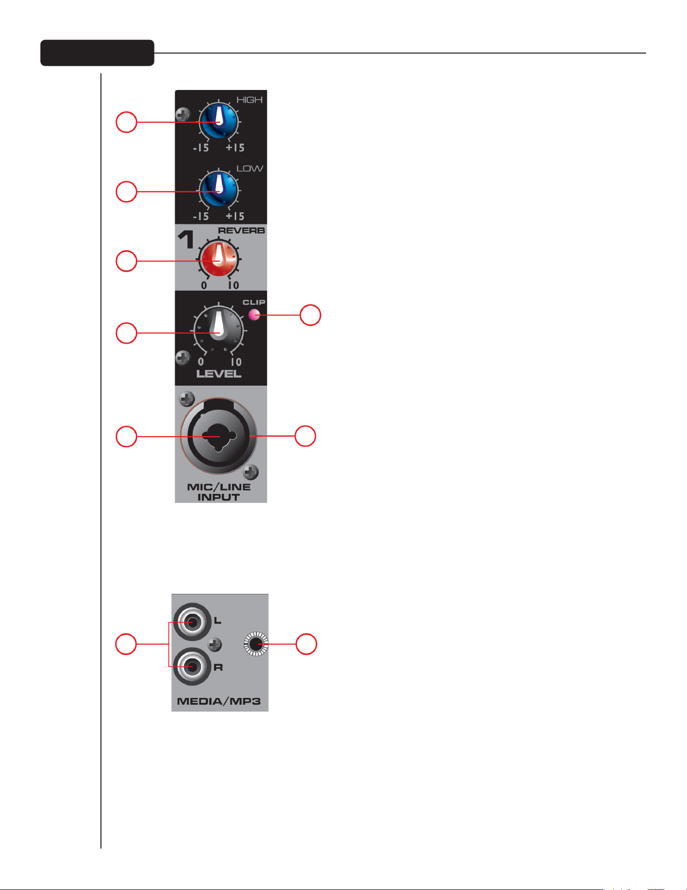
(1) HIGH (TREBLE) TONE CONTROL
An active tone control (shelving type: ±15 dB) that varies the level
of the high frequency range.
(2) LOW (BASS) TONE CONTROL
An active tone control (shelving type: ±15 dB) that varies the level of
the low frequency range.
Caution: Excessive low frequency boost causes greater power
consumption and increases the possibility of speaker damage.
(3) REVERB CONTROL
This is used as a send control to the effects bus. It controls the
amount of reverberation added to the input signals.
(4) LEVEL CONTROL
The level control for each channel sends the signal to the master
mix bus. Typical operation is between 4 and 8 (dependent upon
the input devices) but should be lower than the master level.
Please remember that this acts like a preamp, so if you are using
a device that has a volume output control (i.e., a tape or CD
player) you will need to match the levels by adjusting the level
controls on each unit.
(5) CLIP LED
Indicates when the signal level is within 3 dB of clipping.
(6) 3-PIN (XLR) LOW-IMPEDANCE MICROPHONE INPUT
This input is for typical balanced, low-impedance microphones.
It will automatically provide 15V phantom power for condenser
mics or active direct boxes. This has an input impedance of 1k
ohms. The connector is wired as: Pin 1=shield; Pin 2=positive
(hot); Pin 3=negative (cold).
(7) 1/4" LINE
The 1/4" line input connector is used to connect line-level
sources to the channel input. The line input is typically used for
sources like keyboards and CD players and can be used with the
high level output of wireless microphone receivers. When this
input is used, the XLR mic input is disconnected.
(8A) AND (8B) MEDIA INPUT
These inputs, RCA (8A) and 1/8" (8B) accept a stereo input from
the output of an MP3 player, CD player, tape deck or other similar
device.
Mic/Line Input
1
2
3
4
5
67
8A 8B

8
7
9 10
(7) FLS
®
FEEDBACk LOCATING SYSTEM
The patent FLS Feedback Locating System is a quick and easy way to removing feedback from the system. When
feedback occurs, the LED that corresponds to the frequency band causing feedback will illuminate over the slider
to be adjusted. Slowly bring that slider down until feedback is gone. The LED will remain illuminated for a few
seconds after the feedback is gone. It is normal for the lights to occasionally turn on during a performance. This
does not necessarily mean feedback is occurring.
(8) GRAPHIC EQ
These 5-band EQs are designed for 12dB cut or boost. These EQs are used to make minor adjustments to the
overall mix and should be used sparingly.
(9) AMP LEVEL LED LADDER
These LEDs indicate the signal level going to the power amplifier. The top LED indicates LIMIT and activation of
our revolutionary DDT
™
speaker protection circuit, which is built into the PV 5300 and activates automatically to
maximize the power amplifier without fear of distortion.
(10) MASTER VOLUME
The master level control for the main mix and the overall volume of the powered mixer.
Main EQ / Master Volume
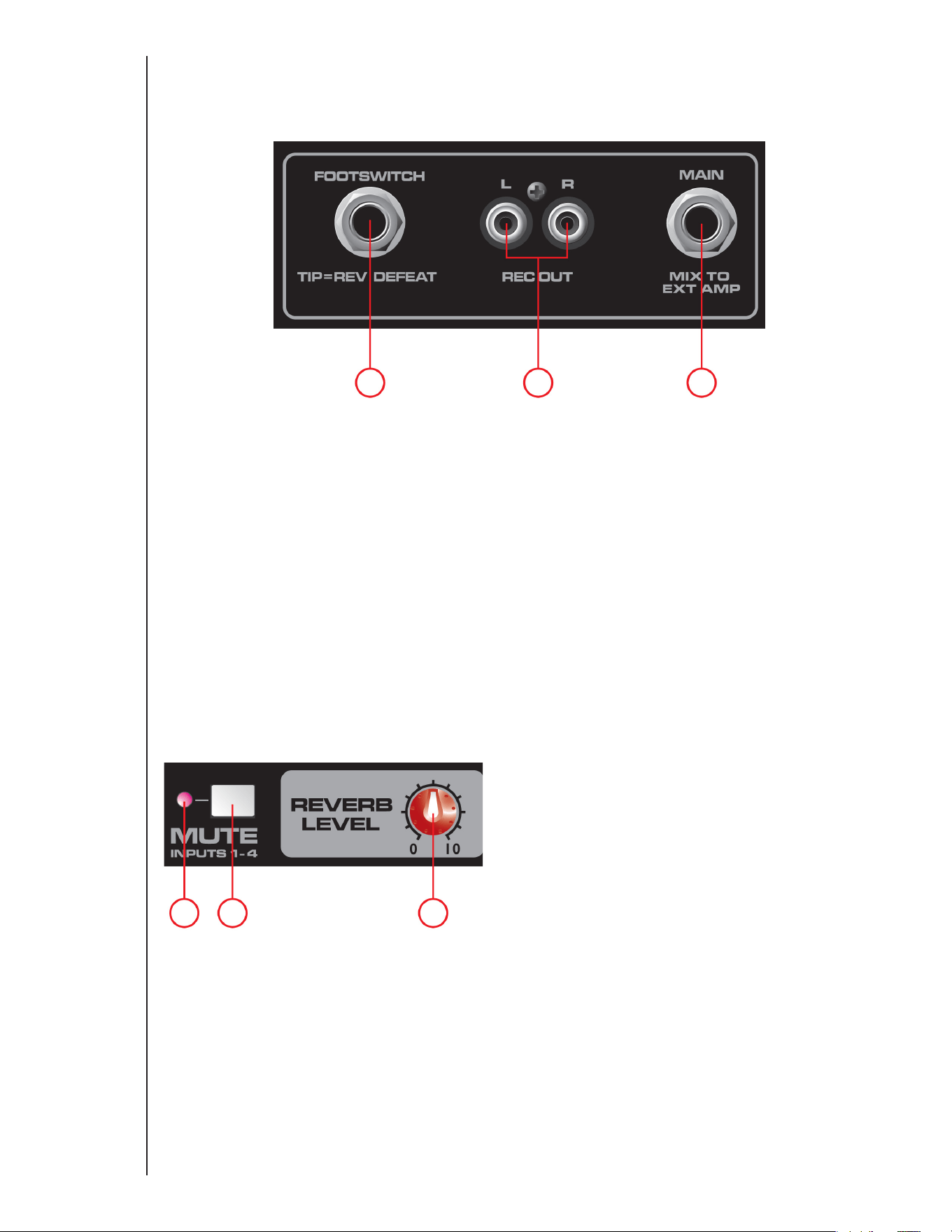
11
14 15 16
12 13
(11) FOOTSWITCH
This 1/4" jack accepts a 1/4" footswitch (Peavey part number
03051000) designed to defeat the Reverb effect on all channels.
(12) REC OUT
This RCA output provides a signal to the recording inputs of a CD
recorder, stereo tape deck or other recording device.
NOTE: Do not connect a single device to both the Rec
Out and Media Input (8A/8B) simultaneously this
setup could create a loop which could cause severe
feedback, potentially damaging your system.
(13) MAIN OUT
This 1/4" jack provides a signal from the main mix (after the
graphic EQ) for an external power amplifier.
(14) MUTE LED
When this LED is illuminated it indicates channels 1-4 are muted
and not passing signal to the power amplifier.
(15) MUTE SWITCH
Depressing this button mutes channels 1-4 preventing signal
from passing to the power amplifier. This button does not
effect channel 5. This function is convenient for breaks between
performances, allowing music to be played through the sound
system while muting the line/mic channels.
(16) MASTER REVERB
Overall level of the Reverb effect on corresponding channels.
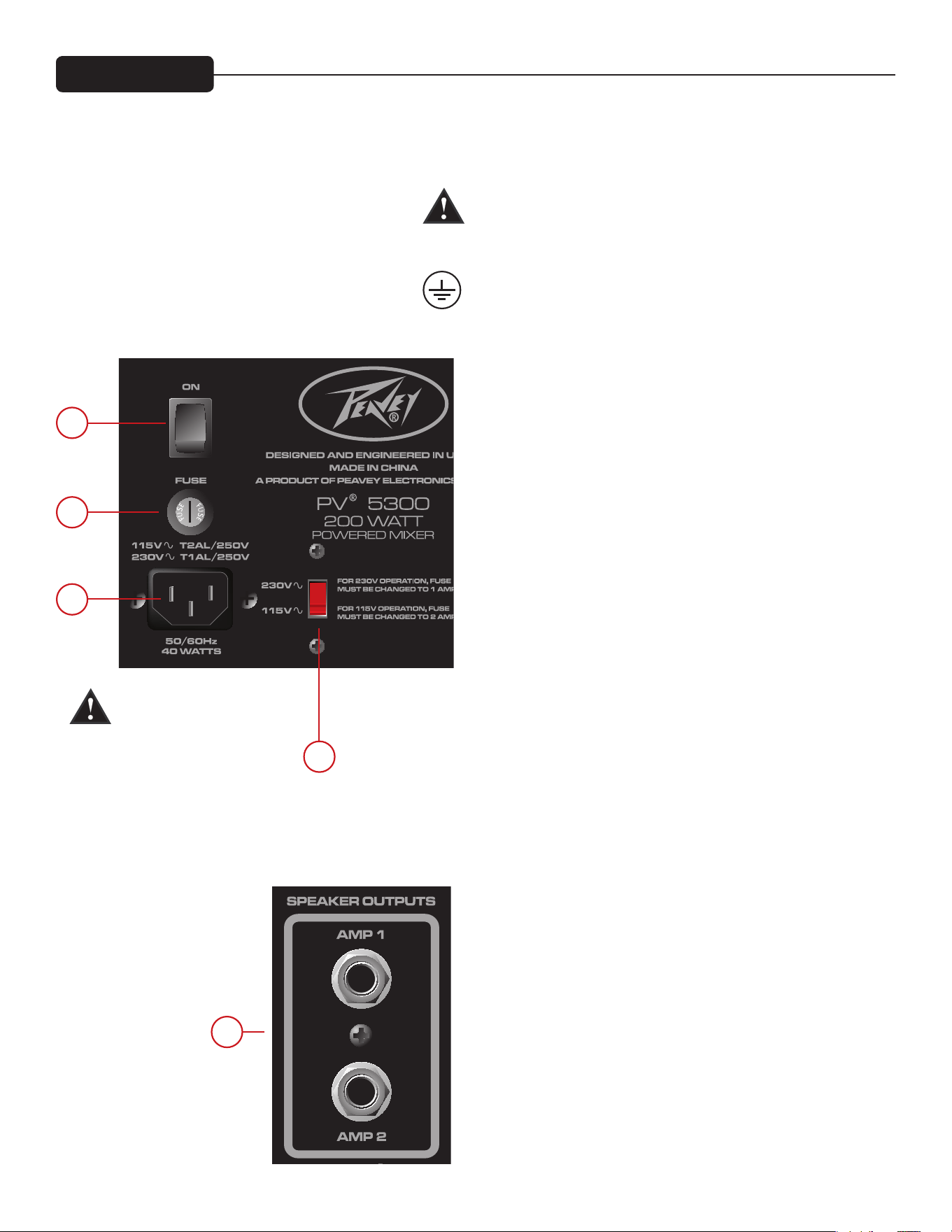
17
18
19
21
20
Back Panel
(17) POWER SWITCH
This is the main power switch.
(18) AC POWER INLET:
This is the receptacle for an IEC line cord, which provides AC
power to the unit. Connect the line cord to this connector to
provide power to the unit. Damage to the equipment may result if
improper line voltage is used. (See line voltage marking on unit)
Never break off the ground pin on any equipment. It is provided
for your safety. If the outlet used does not have a ground pin, a
suitable grounding adapter should be used and the third wire
should be grounded properly.
To prevent the risk of shock or fire hazard, always make sure
that the amplifier and all associated equipment is properly
grounded.
NOTE: FOR U.k. ONLY
As the colors of the wires in the mains lead of this apparatus
may not correspond with the colored markings identifying the
terminals in your plug, proceed as follows:
(1) The wire which is colored green and yellow must be connected
to the terminal which is marked by the letter E, or by the Earth
symbol, or colored green or green and yellow. (2) The wire which
is colored blue must be connected to the terminal which is
marked with the letter N, or the color black. (3) The wire which
is colored brown must be connected to the terminal which is
marked with the letter L, or the color red.
(19) FUSE
This is the main safety fuse for the AC line voltage. Only replace
with a fuse of the exact type and rating. If the fuse continues to
fail, do not replace the fuse again. Take the unit to an authorized
Peavey service center.
NOTE: If the main AC voltage is changed, the fuse must also be
changed to one of the appropriate rating for the voltage you are
switching to.
(20) VOLTAGE SELECTOR SWITCH
This switch allows the user to select between 115VAC / 60Hz or
230VAC / 50Hz. To change the voltage selector, you must first
unscrew and remove the plastic cover that protects the switch.
After changing the voltage, please replace the plastic cover to
ensure the voltage level is not inadvertently altered.
NOTE: The fuse MUST be changed to the appropriate value to
match the voltage you have selected. Please see the note on the
back of the mixer for the correct value.
(21) SPEAkER OUTPUTS
These are two-conductor 1/4" speaker outputs. Each one is rated
at 4 ohms minimum impedance. You may connect either one
4-ohm, one 8-ohm or two 8-ohm speakers to each output. Do not
operate below rated minimum impedance. For maximum power
transfer, be sure to use speaker cables and not instrument cables
to connect to the speakers. We recommend the use of 18-gauge
or larger speaker wire.
NOTE: Before changing
voltage or fuse value, make
sure unit is disconnected
from AC power.
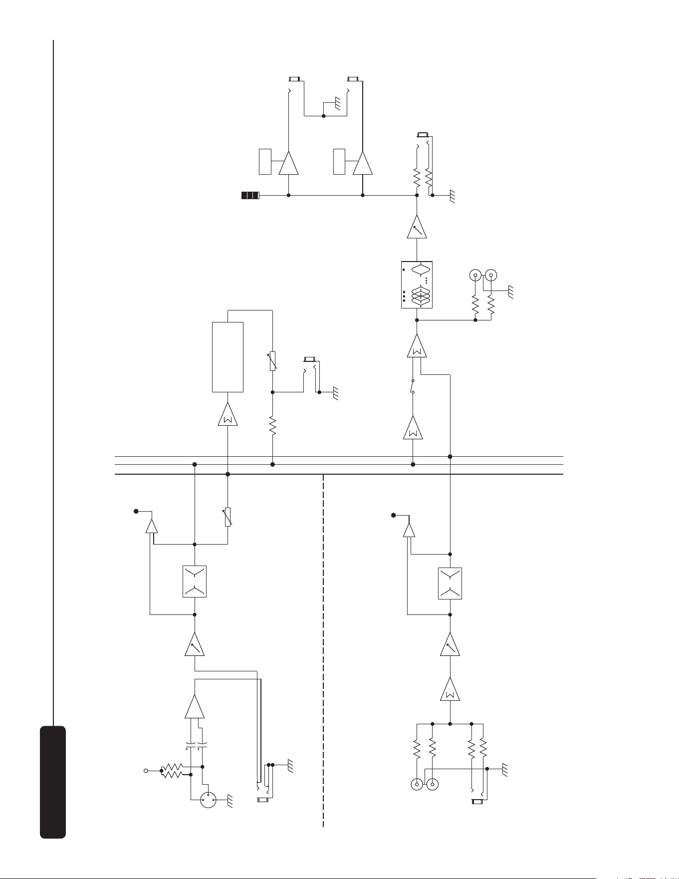
EQ
LO
HI
+15V
EQ
LO
HI
Graphic EQ with FLS
EQ
CLIP
LEFT
MP3 IN
RIGHT
EFX
CLIP
XLR
LINE
MIC PRE
LINE
LEVELSUM
CHANNEL 5
CH 1-4
CH 1-4
CH 5
EQ
MUTE
LEVEL
VOLUME
REC OUT
MASTER5 - BAND EQ
AMP1
AMP2
AMP LEVEL
SPEAKER
OUTPUTS
AMP1
AMP2
CHANNEL 1 - 4
REV
REV LEVEL
REV FOOTSWITCH
MAIN OUT
DIGITAL REVERB
LIMITER
LIMITER
2
3
1
Block Diagram
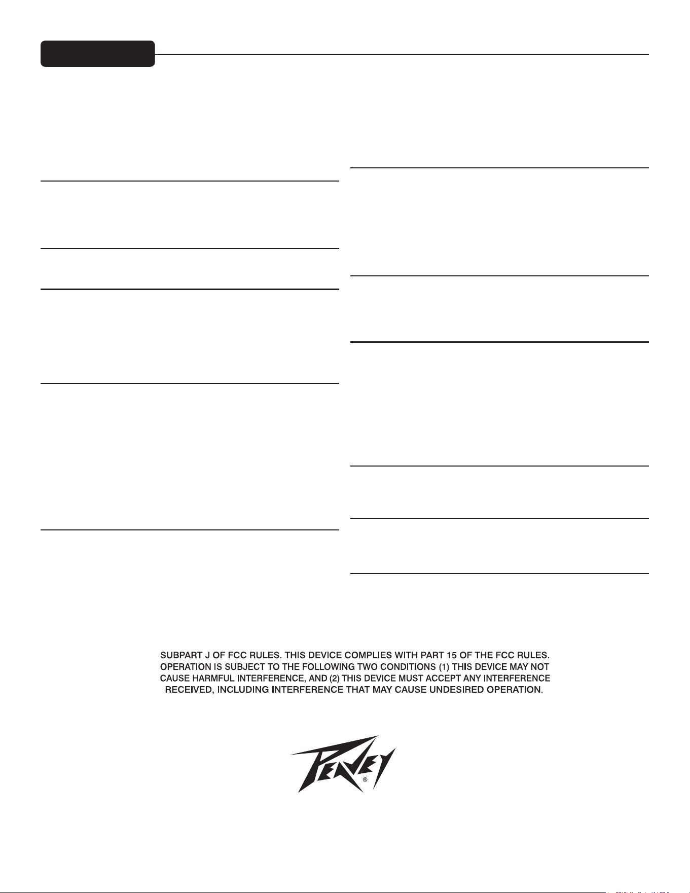
Features and specifications subject to change without notice.
Peavey Electronics Corporation • 5022 Hartley Peavey Drive • Meridian, MS • 39305
(601) 483-5365 • FAX (601) 486-1278 • www.peavey.com • EX 000130 • ©2011
INPUT SENSITIVITY:
Mic In to full power at the power amp. Master Volume Nom.
Full Nominal
-48 dBu -28 dBu
Line In to full power at the power amp. Master Volume Nom.
Full Nominal
-18 dBu +3 dBu
CHANNEL EQ:
Shelving EQ
Low EQ 80 Hz ±15 dB
High EQ 12 kHz ±15 dB
CLIP LED:
Clip LEDs come on 3dB before clipping.
FREQUENCY RESPONSE:
All controls nominal (detent)
Mic to Main 30 Hz – 20 kHz +0, -1 dB
Line to Main 20 Hz – 30 kHz +0, -1 dB
Mic to Amp 50 Hz – 20 kHz +0, -3 dB
Line to Amp 40 Hz – 20 kHz +0, -3 dB
NOISE:
Main = Main line output, 22 – 22kHz filter
Amp 1 = Amplifier output, loaded at 4 ohms, through AP
AUX-0025 switching amplifier filter
All controls full down.
Main <-95 dBu
Amp 1 <-70 dBu
Master Volume nominal
Main <-90 dBu
Amp 1 <-67 dBu
THD:
All controls nominal
<0.01% @ main line output, -30 dBu in mic input
<0.09% @ amp 1 with output adjusted to 45 Watts
All controls nominal
<0.005% @ main line output, +4 dBu in line input
<0.08% @ amp 1 with output adjusted to 45 Watts
MASTER EQ:
80 Hz +/-12 dB
250 Hz +/-12 dB
1 kHz +/-12 dB
3 kHz +/-12 dB
10 kHz +/-12 dB
METER ARRAY:
LIMIT
-6 dB
-12 dB
-18 dB
-24 dB
-30 dB
AMP LIMITER:
Limits amplifier power just before clipping. The limiter holds the amp
power without clipping and can be driven up to 18 dB past maximum
output.
AMPLIFIER OUTPUT POWER:
120VAC
Both channels loaded at 8 ohms: 30 Watts RMS per ch
60 Watts Peak per ch
Both channels loaded at 4 ohms: 50 Watts RMS per ch
100 Watts Peak per ch
POWER REQUIREMENTS:
Domestic: 120VAC 50/60Hz 40 Watts Nominal
Export: 230VAC 50/60Hz 40 Watts Nominal
SIZE:
Dimensions: H x W x D
9” x 14” x 9”
WEIGHT: 14 lbs.
Specifications

2
Mezclador y amplificador
PV
®
5300
Felicitaciones por la compra de su nuevo mezclador y amplificador PV de Peavey
®
. El PV 5300 de Peavey es un
mezclador y amplificador todo en uno, que proporciona hasta cuatro combinaciones de XLR y entradas de 1/4"
mediante los preamplificadores para micrófonos Peavey de primera calidad, y 200 vatios de potencia máxima
de reproducción de sonido claro como un cristal. El PV 5300 de Peavey utiliza funciones exclusivas y patentadas
para ayudar a mejorar con precisión los tonos y la claridad de la voz. El FLS
®
Feedback Locating System identifica
rápida y fácilmente y elimina la retroalimentación. La entrada para un pedal y los complementos incorporados
de reverberación complementan la unidad ya llena de funciones. Conecte casi cualquier cosa a este mezclador
versátil a través de mini conectores de 1/4", RCA y de 1/8" integrados.
Antes de comenzar a usar el mezclador, es muy importante asegurar que el producto reciba un voltaje
de CA apropiado. Puede encontrar el voltaje adecuado para el amplificador impreso al lado del cable
de corriente IEC en el panel posterior de la unidad.
Características:
• FLS
®
Feedback Locating System
• Reverberación digital incorporada
• Combinación de XLR y conectores de entrada de 1/4"
• Ecualizador gráfico de 5 bandas con FLS®
• Silenciador maestro para 1 a 4 canales
• Anulación de efectos con la entrada para pedal
• Entrada de medios de 1/8" RCA
• Sección del amplificador de doble potencia
• Salidas de grabación RCA
• Puente medidor con LED
• Filtrado subsónico del amplificador de potencia
VENTILACION: Para una ventilación adecuada, permita un espacio de 6" (15,5 cm) en todos los lados.
Español
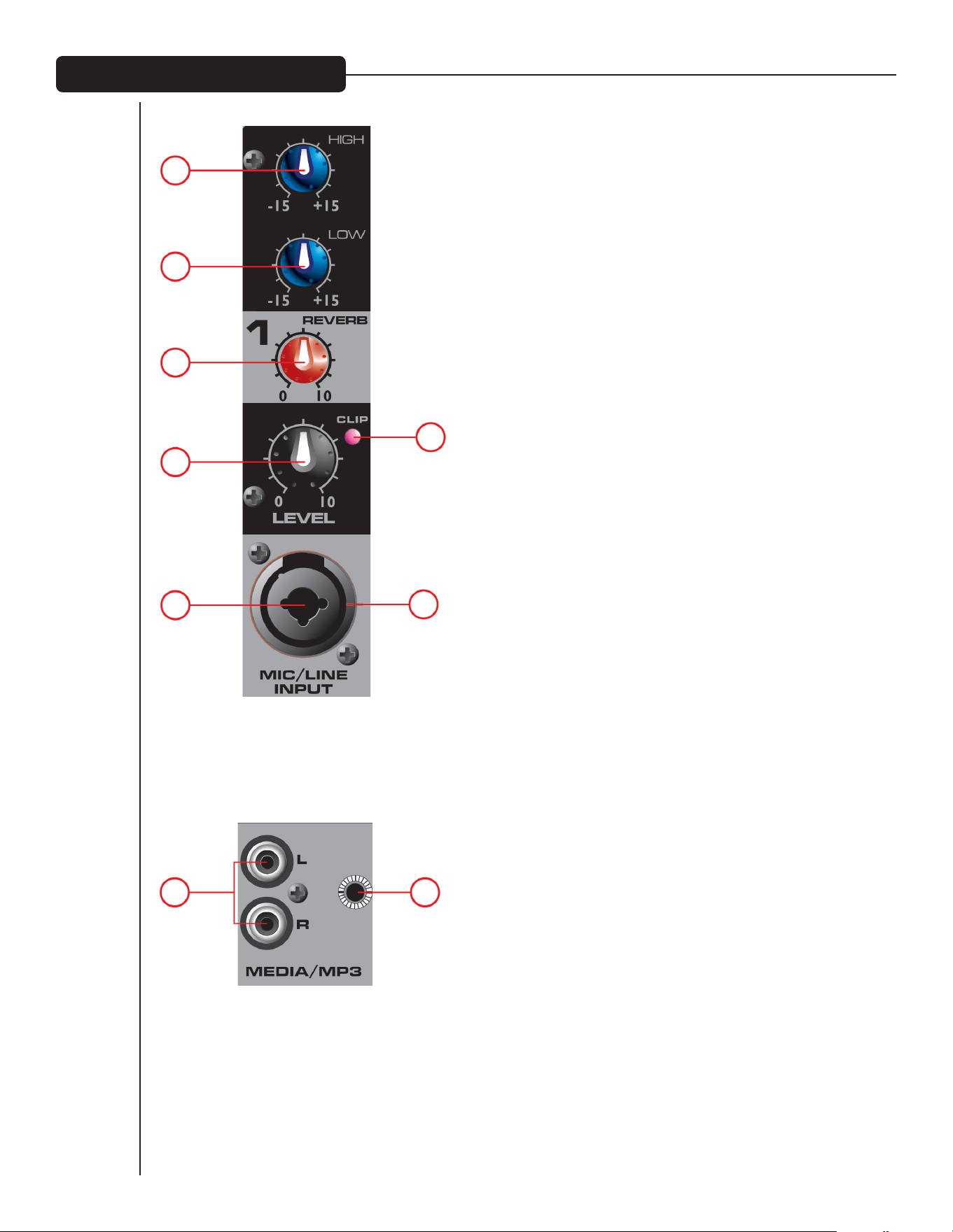
3
(1) CONTROL DE TONO HIGH (TRIPLE)
Un control de tono activo (tipo estantería: ±15 dB) que varía el
nivel del alto rango de frecuencias.
(2) CONTROL DE TONO LOW (BAJO)
Un control de tono activo (tipo estantería: ±15 dB) que varía el nivel
del alto rango de frecuencias.
Precaución: Los aumentos excesivos de bajas frecuencias provocan
mayor consumo de energía y aumenta la posibilidad de daños en los
altoparlantes.
(3) CONTROL REVERB
Este se usa como un control de envío al bus de efectos. Controla
la cantidad de reverberación añadida a las señales de entrada.
(4) CONTROL LEVEL
El control de nivel de cada canal envía la señal al bus de mezcla
maestra. El nivel está entre 4 y 8 (según de los dispositivos de
entrada), pero será inferior al nivel maestro. Éste actúa como
un preamplificador, así que si se usa un dispositivo que tiene
un control de salida del volumen (es decir, una tocacintas o
reproductor de CD) se adecuarán los niveles al ajustar los
controles de nivel de cada unidad.
(5) LED CLIP
Indica cuando la de señal está en 3 dB de mutilación.
(6) MICROPHONE INPUT DE 3 PATITAS (XLR) DE BAJA IMPEDANCIA
Esta entrada es para micrófonos balanceados y de baja
impedancia. Esto proporciona automáticamente una alimentación
fantasma de 15V para micrófonos condensadores o cuadros
directos activos. Esta tiene una impedancia de entrada de 1k
ohmios. El conector está cableado como sigue: Pin 1=protección;
Pin 2=positivo (caliente); Pin 3=negativo (frío).
(7) LINE DE 1/4"
El conector de entrada de línea de 1/4" se usa para conectar
fuentes a nivel de línea al canal de entrada. La entrada de línea
se usa para fuentes como teclados y reproductores de CD y
puede usarse con la salida de alto nivel de los receptores de
micrófonos inalámbricos. Cuando se usa esta entrada, la entrada
del micrófono XLR está desconectada.
ENTRADAS L/R (8A) Y MEDIA (8B)
Estas entradas, RCA (8A) y de 1/8" (8B) aceptan la entrada de
un reproductor de MP3, reproductor de CD, tocacintas u otro
dispositivo similar.
Entrada de línea y del micrófono
1
2
3
4
5
67
8A 8B

4
8
7
9 10
(7) FLS
®
FEEDBACK LOCATING SYSTEM
El FLS Feedback Locating System patentado es una manera rápida y fácil de eliminar la retroalimentación del
sistema. Cuando se produce una retroalimentación, el LED que corresponde a la banda de frecuencia que causa
retroalimentación se iluminará en el control deslizante a ajustarse. Mueva el deslizador lentamente hacia abajo
hasta que desaparezca la retroalimentación. El LED quedará iluminado durante unos segundos después de haber
desaparecido la retroalimentación. Es normal que las luces se enciendan ocasionalmente en funcionamiento.
Esto no significa que se está produciendo una retroalimentación.
(8) EQ GRÁFICO
Estos EQs de 5 bandas están diseñados para mutilaciones o aumentos de 12dB. Estos EQs se utilizan para
realizar pequeños ajustes en la mezcla general y deben usarse con moderación.
(9) ESCALERA DE LED AMP LEVEL
Estos LED indican el nivel de señal que va al amplificador de potencia. El LED superior indica LIMIT y la activación
automática del revolucionario circuito de protección de altoparlantes DDT
™
, que está integrado en el PV 5300
para maximizar el amplificador de potencia sin temor de distorsión.
(10) MASTERVOLUME
El control del nivel maestro sirve para la mezcla principal y el volumen total del mezclador.
Ecualizador principal / Volumen maestro
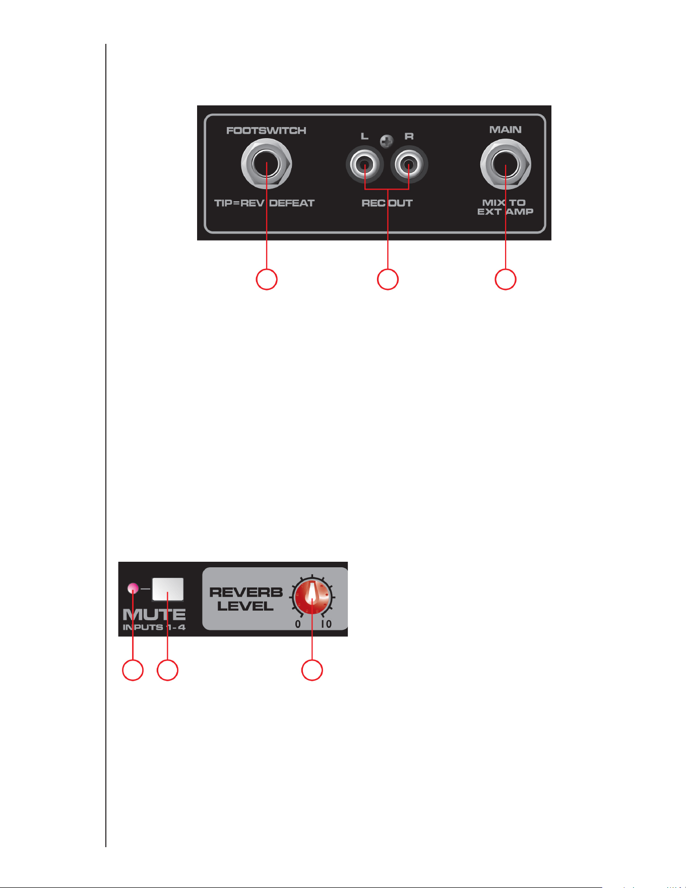
5
11
14 15 16
12 13
(11) FOOT INTERRUPTOR
Este conector de 1/4" jack acepta una entrada para pedal de 1/4" (Parte
número 03051000 de Peavey) y está diseñado para anular el efecto de
reverberación en todos los canales.
(12) REC OUT
Esta salida RCA proporciona una señal a las entradas de grabación de
una grabadora de CD, tocacintas estereofónico u otro dispositivo de
grabación.
NOTA: No conecte un dispositivo tanto a la salida
de grabación como a la salida de medios (8A/ 8B)
simultáneamente ya que esto puede crear un bucle que
causará retroalimentaciones graves que pueden dañar su
sistema.
(13) SALIDA MAIN
Este conector de 1/4" proporciona una señal de la mezcla principal
(después del EQ gráfico) para un amplificador de potencia externa.
(14) LED MUTE
Cuando este LED se ilumina, indica que los canales 1 a 4 están en silencio
y que no se está pasando señal al amplificador de potencia.
(15) INTERRUPTOR MUTE
Presionar este botón silenciará los canales 1 a 4 para que no pase
ninguna señal al amplificador de potencia. Este botón no afecta al canal
5. Esta función es útil para pausas convenientes entre interpretaciones
lo que permite que la música se escuche en el sistema de sonido
mientras se silencian los canales de línea y micrófono.
(16) REVERB MAESTRO
Nivel general del efecto de reverberación en los canales correspondientes.

6
17
18
19
21
20
Panel posterior
(17) INTERRUPTOR DE ELECTRICIDAD
Este es el interruptor principal.
(18) ENTRADA DE ALIMENTACIÓN DE CA:
Este es el receptáculo para un cable de corriente IEC, con un
adaptador de CA a la unidad. Conecte el cable de corriente que
provee CA a la unidad. Se pueden causar daños al equipo si se
utiliza un voltaje de línea inapropiado. (Consulte la marca de
voltaje de la línea en la unidad).
Nunca rompa la patita de conexión a tierra en ningún equipo. Se
proporciona por su seguridad. Si el enchufe no tiene una patita
de conexión a tierra, se usará un adaptador adecuado y el tercer
cable de conectarse a tierra apropiadamente.
Para prevenir el riesgo de riesgo de incendio, siempre asegúrese
de que el amplificador y todos los equipos estén debidamente
conectados.
NOTE: FOR U.K. ONLY
As the colors of the wires in the mains lead of this apparatus
may not correspond with the colored markings identifying the
terminals in your plug, proceed as follows:
(1) The wire which is colored green and yellow must be connected
to the terminal which is marked by the letter E, or by the Earth
symbol, or colored green or green and yellow. (2) The wire
which is colored blue must be connected to the terminal which
is marked with the letter N, or the color black. (3) The wire which
is colored brown must be connected to the terminal which is
marked with the letter L, or the color red.
(19) FUSE
Este es el fusible principal de seguridad para el voltaje de línea
de CA. Sólo cámbielo con un fusible del tipo exacto. Si el fusible
se abre otra vez, no lo cambie. Lleve la unidad al centro de
servicio autorizado de Peavey.
NOTA: Si se cambia el voltaje de CA principal, el fusible también
se cambiará con uno del tipo apropiado para el voltaje que piensa
cambiar.
(20) INTERRUPTOR SELECTOR DE VOLTAJE
Este interruptor le permite al usuario seleccionar entre 115VCA
/ 60Hz o 230VCA / 50Hz. Para cambiar el selector de voltaje,
se debe primero destornillar y quitar la cubierta plástica que
protege al interruptor. Después de cambiar el voltaje, cambie la
cubierta plástica para garantizar el nivel de voltaje no se haya
alterado inadvertidamente.
NOTA: El fusible DEBE cambiarse al valor apropiado para que
coincida con el voltaje que ha seleccionado. Por favor lea la nota
en la parte posterior del mezclador para el valor correcto.
(21) SPEAKER OUTPUTS
Estas son dos salidas para altoparlantes de 1/4" de dos conductores.
Cada una se clasifica con 4 ohmios de impedancia mínima. Se
podrán conectar un altoparlante de 4 ohmios, uno de 8 ohmios
o dos de 8 ohmios a cada salida. No las utilice por debajo de la
impedancia nominal mínima. Para lograr la máxima transferencia
de potencia, asegúrese de usar cables de altoparlantes y no cables
de instrumentos para conectar los altoparlantes. Se recomienda
usar cables de calibre 18 o superior.
NOTA: Antes de cambiar
el voltaje o el valor del
fusible, asegúrese de
desconectar la unidad de
la fuente de alimentación
de CA.

Características y especificaciones sujetas a cambios sin previo aviso.
Peavey Electronics Corporation • 5022 Hartley Peavey Drive • Meridian, MS • 39305
(601) 483-5365 • FAX (601) 486-1278 • www.peavey.com • EX 000130 • ©2011
SENSIBILIDAD DE ENTRADA:
Mic In para potencia total en el amp. Vol. maestro normal.
Total Nominal
-48 dBu -28 dBu
Line In para potencia total en el amp. Vol. maestro normal.
Total Nominal
-18 dBu +3 dBu
EQ DE CANAL:
EQ de estantería
EQ bajo 80 Hz ±15 dB
EQ alto 12 kHz ±15 dB
LED DE MUTILACIÓN:
Los LED de mutilación vienen en 3dB antes de la mutilación.
RESPUESTA DE FRECUENCIA:
Todos los controles nominales (detente)
Mic. al principal 30 Hz – 20 kHz +0, -1 dB
Línea al principal 20 Hz – 30 kHz +0, -1 dB
Mic. al amplificador 50 Hz – 20 kHz +0, -3 dB
Línea al amplificador 40 Hz – 20 kHz +0, -3 dB
RUIDO:
Principal = salida de línea principal, filtro de 22 - 22kHzr
Amp 1 = salida del amplificador, cargadi a 4 ohmios, por AP
Filtro del amplificador cambiante AUX-0025
Todos los controles totalmente abajo.
Princiapal <-95 dBu
Amp 1 <-70 dBu
Volumen maestro nominal
Principal <-90 dBu
Amp 1 <-67 dBu
THD:
Todos los controles nominales
<0,01% @ salida de línea princ., -30 dBu en entrada mic.
<0,09% @ amp 1 sin salida ajustada a 45 vatios
Todos los controles nominales
<0,005% @ salida línea prin., +4 dBu en salida de línea entrada
<o,o8% @ amp 1 sin salida ajustada a 45 vatios
EQ MAESTRO:
80 Hz +/-12 dB
250 Hz +/-12 dB
1 kHz +/-12 dB
3 kHz +/-12 dB
10 kHz +/-12 dB
ARREGLO DEL MEDIDOR:
LÍMITE
-6 dB
-12 dB
-18 dB
-24 dB
-30 dB
LIMITADOR DEL AMPLIFICADOR:
Limita la potencia del amplificador antes de la mutilación. El limitador
mantiene al amplificador sin mutilación y puede llevarse a una salida
máxima de 18 dB.
POTENCIA DE SALIDA DEL AMPLIFICADOR:
120VAC
Dos canales cargados a 8 ohmios: 30 vatios RMS por canal
60 vatios máx. por canal
Dos canales cargados a 8 ohmios: 50 vatios RMS por canal
100 vatios máx. por canal
REQUISITOS DE ENERGIA:
Nacional: 120VCA 50/60HZ 4o vatios Nominal
Exportación: 230VCA 50/60HZ 4o vatios Nominal
TAMAÑO:
Dimensiones: Alto x Ancho x Profundidad
9" x 14" x 9"
PESO: 14 libras
Especificaciones
SUBPARTE J DE LAS REGLAS DE FCC. ESTE DISPOSITIVO CUMPLE CON LA
SECCIÓN 15 DE LAS REGLAS DE FCC. SU FUNCIONAMIENTO ESTÁ SUJETO A LAS
DOS CONDICIONES SIGUIENTES: (1) ESTE DISPOSITIVO NO PUEDE CAUSAR
INTERFERENCIAS DAÑINAS, Y (2) ESTE DISPOSITIVO DEBE ACEPTAR CUALQUIER
INTERFERENCIA RECIBIDA, INCLUSO LA INTERFERENCIA QUE PUEDA CAUSAR UN
FUNCIONAMIENTO NO DESEADO.

2
Amplificateur table de mixage
PV
®
5300
Félicitation pour l'achat de votre nouvel amplificateur table de mixage PV de chez Peavey
®
. Le Peavey PV 5300
est un amplificateur table de mixage tout-en-un, offrant quatre entrées combinés XLR et 1/4" mettant en œuvre
des préamplificateurs de microphone de haute qualité Peavey, et avec une puissante de crête de 200 watts pour
une reproduction audio claire comme du cristal. Le Peavey PV 5300 met en œuvre des fonctionnalités exclusives
et brevetées pour aider à améliorer fidèlement le ton et la clarté du chant. Notre système FLS
®
(Feedback Locating
System ou Système de détection d'effet Larsen) identifie et élimine rapidement et facilement la rétroaction
acoustique (effet Larsen). L'effet de réverbération intégré, à commande au pied, complémente l'appareil déjà
riche en fonctionnalités. Il est possible de brancher presque tout à cet amplificateur table de mixage polyvalent à
l'aide des prises intégrées de 1/4", RCA et 1/8" mini.
Avant d'utiliser vote amplificateur table de mixage, il est important de vous assurer que le produit est
configuré avec la tension d'alimentation CA correcte. La tension correcte pour votre amplificateur est
indiquée près de la prise IEC du cordon d'alimentation sur le panneau arrière de l'appareil.
Caractéristiques :
• FLS
®
Feedback Locating System (système de détection d'effet Larsen)
• Effet numérique de réverbération intégré
• Combinaison de prise d'entrée XLR et 1/4"
• Égaliseur (EQ) graphique à 5 bandes graphique avec système FLS
®
• Fonction Mute (Muet) principale pour les canaux 1-4
• Annulation des effets par pédale
• Entrée multimédia 1/8" RCA
• Amplificateur de puissant à double section
• Sorties d'enregistrement RCA
• Vumètre en rail à diodes lumineuses
• Filtrage subsonique de l'amplificateur de puissance
AÉRATION : Pour une correcte ventilation, laissez un espace libre de 15,5 cm (6") sur tous les côtés.
Français

3
(1) COMMANDE DE TONALITÉ (AIGU) - HIGH
Une commande de tonalité active (de type à correction en
dégradé : ±15 dB) qui modifie le niveau de la plage des hautes
fréquences.
(2) COMMANDE DE TONALITÉ (GRAVE) - LOW
Une commande de tonalité active (de type à correction en dégradé :
±15 dB) qui modifie le niveau de la plage des basses fréquences.
Attention : Une amplification excessive des fréquences basses
augmente fortement la consommation électrique et le risque de
détérioration des haut-parleurs.
(3) COMMANDE DE RÉVERBÉRATION - REVERB
Cette commande est utilisée comme une commande de départ du
bus d'effet. Elle contrôle la quantité de réverbération ajoutée aux
signaux d'entrée.
(4) COMMANDE DE NIVEAU - LEVEL
Cette commande de niveau pour chaque voie envoie le signal au
bus de mixage principal. La commande est typiquement entre
4 et 8 (en fonction des dispositifs d'entrée) mais elle doit être
inférieure au niveau principal. Veuillez vous souvenir qu'elle agit
comme un préamplificateur, donc si vous utilisez un dispositif qui
a une commande de sortie de volume (c.à.d. un lecteur CD ou de
cassette), vous aurez besoin d'adapter les niveaux en ajustant
les commandes de niveau de chaque appareil.
(5) VOYANT LUMINEUX D'ÉCRÊTAGE - CLIP
Il indique que le niveau de signal atteint 3 dB d'écrêtage.
(6) ENTRÉE DE MICROPHONE À FAIBLE IMPÉDANCE À 3 BROCHES
(XLR) - MICROPHONE INPUT
Cet entrée est conçue typiquement pour les microphones à
faible impédance et balancée. Elle fournira automatiquement
une alimentation fantôme de 15 V pour les microphones à
condensateur ou les boîtiers d'adaptation actifs. L'entrée
d'impédance est de 1k ohms. Le câblage du connecteur est :
Broche 1 = blindage; Broche 2 = positif (chaud); Broche 3 =
négatif (froid).
(7) ENTRÉE DE LIGNE 1/4" - LINE
Le connecteur d'entrée de ligne est utilisé pour connecter les
sources de niveau ligne à la voie d'entrée. L'entrée de ligne est
utilisée typiquement pour les sources comme les claviers et les
lecteurs CD et peut être utilisée avec la sortie de niveau élevé
des récepteurs de microphone sans fil. Quand cette entrée est
utilisée, l'entrée de microphone XLR est déconnectée.
(8A) ET (8B) ENTRÉE MULTIMÉDIA - MEDIA
Ces entrées par fiche RCA (8A) et 1/8" (8B) acceptent une entrée
stéréo comme la sortie d'un lecteur MP3, d'un lecteur CD, de
magnétophone ou d'autre dispositif similaire.
Entrée de ligne / microphone
1
2
3
4
5
67
8A 8B
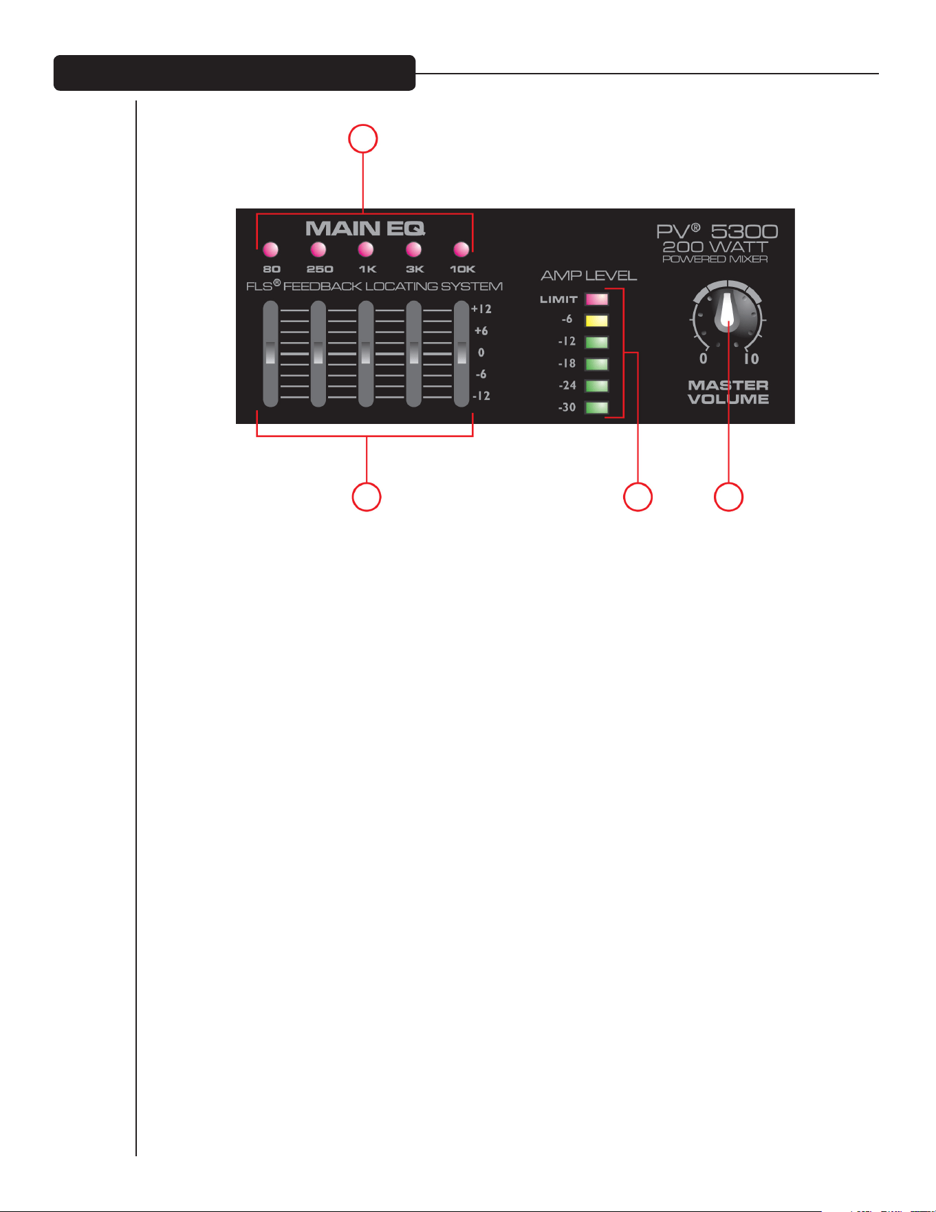
4
8
7
9 10
(7) FLS
®
FEEDBACK LOCATING SYSTEM
Le système breveté FLS Feedback Locating System (Système de détection d'effet Larsen) est un moyen rapide
et facile d'éliminer la rétroaction acoustique du système. Lorsqu'un effet Larsen est produit, le voyant lumineux
qui correspond à la bande de fréquence de cette rétroaction acoustique s'allumera au-dessus du potentiomètre
linéaire à ajuster. Abaissez lentement ce gradateur jusqu'à ce que l'effet Larsen disparaisse. Le voyant reste
allumé pendant quelques secondes après la disparition de l'effet Larsen. Il est normal que le voyant s'éclaire
occasionnellement lors d'une exécution. Le voyant n'indique pas nécessairement la présence d'une rétroaction
acoustique.
(8) ÉGALISEUR GRAPHIQUE - EQ
Cet égaliseur EQ à 5 bandes est conçu pour des amplifications ou des atténuations à 12dB. Cet égaliseur EQ est
utilisé pour corriger légèrement le mixage global et doit être utilisé avec modération.
(9) VUMÈTRE À DIODE DE NIVEAU D'AMPLIFICATION - AMP LEVEL
Ces voyants lumineux indiquent le niveau de signal destiné à l'amplificateur de puissance. Le voyant lumineux
du haut LIMIT indique l'activation de notre circuit révolutionnaire de protection de haut-parleur DDT
™
, intégré
à l'amplificateur table de mixage PV 5300. Le circuit s'active automatiquement pour optimiser la puissance de
l'amplificateur sans craindre la distorsion.
(10) VOLUME PRINCIPAL – MASTER VOLUME
C'est la commande de niveau principal du mixage principal et du volume globale de l'amplificateur table de
mixage.
Égaliseur (EQ) principal / Volume principal

5
11
14 15 16
12 13
(11) COMMANDE PAR PÉDALE - FOOTSWITCH
Cette prise 1/4" accepte une pédale 1/4" (Numéro de pièce Peavey
03051000) conçu pour annuler l'effet de réverbération sur tous les
canaux.
(12) SORTIE D'ENREGISTREMENT - REC OUT
Cette sortie RCA fournit un signal aux entrées d'enregistrement de graveur
de CD, de magnétophone ou d'autre dispositif d'enregistrement.
NOTE : Ne pas connecter un même appareil à la fois à
la sortie Rec Out et à l'entrée multimédia (Media input)
simultanément. Cette configuration pourrait créer une boucle
qui pourrait produire d'importantes rétroactions acoustiques
qui risqueraient d'endommager votre système.
(13) SORTIE PRINCIPALE - MAIN OUT
Cette prise 1/4" délivre un signal du mixage principal (après l'égaliseur
EQ graphique) pour un amplificateur de puissance externe.
(14) VOYANT LUMINEUX DE COUPURE DU SON - MUTE
Quand le voyant est allumé, il indique que le son des voies 1-4 est coupé
et que le signal n'est pas délivré à l'amplificateur de puissance.
(15) COMMUTATEUR DE COUPURE DU SON - MUTE
Si vous enfoncez ce bouton, le son des voies 1-4 est coupé, empêchant
le signal d'atteindre l'amplificateur de puissance. Ce bouton n'a aucun
effet sur la voie 5. Cette fonction est pratique lors des pauses entre les
exécutions, autorisant la musique à être jouée par le système sonore
alors que le son des voies de ligne ou de microphone est coupé.
(16) FONCTION REVERB PRINCIPAL
Elle commande le niveau global de l'effet de réverbération des voies
correspondantes.

6
17
18
19
21
20
Panneau arrière
(17) COMMUTATEUR D'ALIMENTATION
C'est le commutateur principal d'alimentation.
(18) PRISE D'ALIMENTATION CA :
C'est la fiche de branchement du cordon d'alimentation IEC, qui
fournit l'alimentation électrique à l'appareil. Connecter le cordon à
ce connecteur pour alimenter l'appareil. Si la tension d'alimentation
utilisée n'est pas correcte, des dommages à l'équipement peuvent en
résulter. (Voir l'étiquette de tension d'alimentation sur l'appareil)
Ne jamais supprimer la broche de mise à la terre d'un équipement. Elle
est prévue pour votre sécurité. Si la prise utilisée ne possède pas de
broche de mise à la terre, un adaptateur de mise à la terre adéquat doit
être utilisé et le troisième fil doit être relié à la terre correctement.
Pour éviter tout risque de choc électrique ou d'incendie, assurez-vous
toujours que l'amplificateur et tous les équipements associés sont
correctement mis à la terre.
NOTE: FOR U.K. ONLY
As the colors of the wires in the mains lead of this apparatus may not
correspond with the colored markings identifying the terminals in your
plug, proceed as follows:
(1) The wire which is colored green and yellow must be connected to
the terminal which is marked by the letter E, or by the Earth symbol, or
colored green or green and yellow. (2) The wire which is colored blue
must be connected to the terminal which is marked with the letter N, or
the color black. (3) The wire which is colored brown must be connected
to the terminal which is marked with the letter L, or the color red.
(19) FUSE
C'est le fusible de protection principal de tension d'alimentation CA.
Remplacez-le uniquement par un fusible de même type et de même
ampérage. Si le fusible continue à griller, ne pas insister. Portez
l'appareil à un centre de réparation autorisé Peavey.
NOTE : Si la tension de secteur CA est modifiée, le fusible doit aussi être
changé par un autre approprié à l'ampérage et à la nouvelle tension.
(20) COMMUTATEUR DE SÉLECTION DE TENSION
Ce commutateur permet à l'utilisateur de choisir entre la tension
d'alimentation 115 V CA / 60 Hz et 230 V CA / 50 Hz. Pour modifier le
sélecteur de tension, vous devez d'abord dévissez et retirez le couvercle
en plastique qui protège le commutateur. Après avoir modifié la tension,
veuillez remonter le couvercle en plastique afin de veiller à ce que la
valeur de tension ne soit pas altérée par inadvertance.
NOTE : Le fusible DOIT être remplacé par un autre de valeur appropriée,
correspondant à la tension que vous avez sélectionnée. Veuillez lire
les précautions sur l'arrière de l'amplificateur table de mixage pour
identifier la valeur correcte.
(21) SPEAKER OUTPUTS
Deux conducteurs 1/4" de sorties de haut-parleurs sont présents.
Chacun est dimensionné à 4 ohms d'impédance minimale. Vous pouvez
brancher soit un haut-parleur de 4 ohms, soit un de 8 ohms ou deux de
8 ohms à chaque sortie. Ne pas utiliser des haut-parleurs en-dessous
de l'impédance minimale nominale. Pour une puissance de transfert
maximale, assurez-vous d'utiliser des câbles de haut-parleur et non
des câbles d'instrument pour connecter les haut-parleurs. Nous vous
recommandons l'utilisation de câble pour haut-parleur de 1 mm ou
plus.
NOTE: Avant de changer
la valeur de tension ou
le fusible, assurez-vous
d'avoir débranché
l'appareil de l'alimentation
électrique CA.

Les fonctionnalités et les spécifications sont soumises à modification sans avis.
Peavey Electronics Corporation • 5022 Hartley Peavey Drive • Meridian, MS • 39305
(601) 483-5365 • FAX (601) 486-1278 • www.peavey.com • EX 000130 • ©2011
SENSIBILITÉ D'ENTRÉE :
Entrée micro à pleine puissance de l'ampli. de puissance. Volume
principal normalisé.
Plein Nominal
-48 dBu -28 dBu
Entrée de ligne à pleine puissance de l'ampli. de puissance. Volume
principal normalisé.
Plein Nominal
-18 dBu +3 dBu
ÉGALISEUR (EQ) DE VOIE :
Égaliseur à correction en dégradé
Bande basses fréquences 80 Hz ±15 dB
Bande hautes fréquences 12 kHz ±15 dB
VOYANT D'ÉCRÊTAGE :
Le voyant s'allume à 3 dB avant l'écrêtage.
RÉPONSE EN FRÉQUENCE :
Toutes les commandes nominales (cran d'arrêt)
Du microphone au bus principal 30 Hz – 20 kHz +0, -1 dB
De ligne au bus principal 20 Hz – 30 kHz +0, -1 dB
Du microphone à l'amplificateur 50 Hz – 20 kHz +0, -3 dB
De ligne à l'amplificateur 40 Hz – 20 kHz +0, -3 dB
BRUIT :
Principal = Sortie de ligne principale, filtre 22 - 22 kHz
Amp 1 = Sortie amplifiée, avec une charge de 4 ohms, à travers tous
les filtres (All Pass)
Filtre de commutation d'amplificateur AUX-0025
Toutes les commandes baissées.
Principal <-95 dBu
Amp 1 <-70 dBu
Volume principal nominal
Principal <-90 dBu
Amp 1 <-67 dBu
TAUX DE DISTORSION HARMONIQUE (THD) :
Toutes les commandes nominales
<0,01 % en sortie de ligne principale, -30 dBu en entrée de micro
<0,09 % sur Amp 1 avec sortie ajustée à 45 Watts
Toutes les commandes nominales
<0,005 % en sortie de ligne principale, +4 dBu en entrée de ligne
<0,08 % sur Amp 1 avec sortie ajustée à 45 Watts
ÉGALISEUR (EQ) PRINCIPAL :
80 Hz +/-12 dB
250 Hz +/-12 dB
1 kHz +/-12 dB
3 kHz +/-12 dB
10 kHz +/-12 dB
ÉCHELLE DU VUMÈTRE
LIMITE (LIMIT)
-6 dB
-12 dB
-18 dB
-24 dB
-30 dB
AMPLIFICATEUR ÉCRÊTEUR
Il limite la puissance de l'amplificateur juste avant l'écrêtage. Le
limiteur support la puissance de l'amplificateur sans écrêtage et peut
prendre en charge au-delà de 18 dB de la sortie maximale.
PUISSANCE DE SORTIE DE L'AMPLIFICATEUR :
120 V CA
2 canaux chargés sous 8 ohms : 30 Watts RMS par voie
60 Watts RMS par voie
2 canaux chargés sous 4 ohms : 50 Watts RMS par voie
100 Watts RMS par voie
ALIMENTATION :
Domestique : 120 V CA 50 / 60HZ 40 Watts Nominal
Exportation : 30 V CA50 / 60HZ 40 Watts Nominal
DIMENSION :
Dimensions : Hauteur x Largeur x Profondeur
22,9 cm x 35,6 cm x 22,9 cm
POIDS : 6,4 kg
Spécifications
SOUS-PARTIE J DU RÈGLEMENT DE LA FCC. CET APPAREIL EST CONFORME À L'ARTICLE 15 DU RÈGLE-
MENT DE LA FCC. L'UTILISATION EST SUJETTE AUX DEUX CONDITIONS SUIVANTES (1) CET APPAREIL NE
DOIT PAS ENGENDRER DES INTERFÉRENCES NUISIBLES, ET (2) CET APPAREIL DOIT ACCEPTER TOUTE
INTERFÉRENCE REÇUE, Y COMPRIS LES INTERFÉRENCES QUI POURRAIENT AVOIR DES EFFETS NON
DÉSIRÉS SUR SON FONCTIONNEMENT.

2
PV
®
5300
Aktives Mischpult
Herzlichen Glückwunsch zum Kauf Ihres neuen aktiven PV-Mischpults von Peavey®. Das Peavey PV 5300 ist ein
aktives All-in-One Mischpult und bietet bis zu vier Kombinationen XLR- und 1/4-Zoll-Eingänge mit Premium Peavey
Mikrofon-Vorverstärkern und 200 Watt Spitzenleistung für kristallklare Audiowiedergabe. Das Peavey PV 5300
benutzt exklusive und patentierte Funktionen zur genauen Verbesserung von Ton und Klarheit der Gesangsstimmen.
Unser patentiertes und revolutionäres FLS® Feedback Locating System identifiziert Rückkopplungen schnell
und schaltet sie aus. Fußschaltbar und integrierter Hall ergänzen das bereits funktionsgeladene Gerät. Sie
können nahezu alles an diesem vielseitigen Mischpult über die 1/4-Zoll-, RCA- (Cinch-) und 1/8-Zoll-Miniklinken
anschließen.
Bevor Sie Ihr aktives Mischpult benutzen, muss unbedingt die korrekte Netzspannung eingestellt
werden. Die korrekte Spannung für Ihren Verstärker ist neben dem IEC-Netzanschluss auf der
Rückseite des Geräts aufgedruckt.
Ausstattungsmerkmale:
• FLS
®
Feedback Locating System
• Digitaler Hall
• Kombination XLR- und 1/4-Zoll-Eingänge
• 5-Band grafischer EQ mit FLS
®
• Master-Stummschaltung für Kanäle 1-4
• Fußschaltbare Effekte
• RCA, 1/8-Zoll-Medieneingang
• Dualer Verstärkerabschnitt
• RCA-Aufnahmeausgänge
• LED-Meter
• Verstärker Trittschallfilterung
VENTILATION: Für ausreichende Ventilation lassen Sie ringsum 15,5 cm Abstand an allen Seiten.
Deutsch
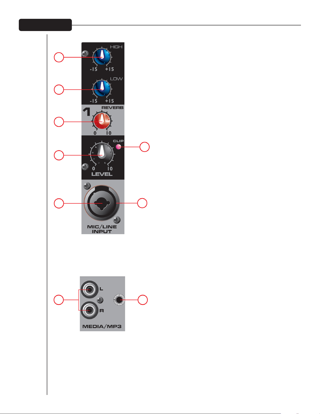
3
(1) HIGH (HÖHEN) KLANGSTEUERUNG
Eine aktive Klangsteuerung (Shelving Typ: ±15 dB) zur Änderung
des Pegels des hohen Frequenzbereichs.
(2) LOW (BASS) KLANGSTEUERUNG
Eine aktive Klangsteuerung (Shelving Typ: ±15 dB) zur Änderung des
Pegels des unteren Frequenzbereichs.
Vorsicht: Übermäßige Niederfrequenzverstärkung führt zu größerer
Leistungsaufnahme und erhöht die Gefahr der Beschädigung von
Lautsprechern.
(3) REVERB STEUERUNG
Dies wird als Send-Steuerung zum Effektbus benutzt. Steuert die
Menge zugefügten Halls in den Eingangssignalen.
(4) LEVEL STEUERUNG
Pegelsteuerung für jeden Kanal sendet das Signal an den
Master-Mixbus. Typischer Betrieb ist zwischen 4 und 8 (abhängig
von Eingangsgeräten), sollte jedoch niedriger als der Masterpegel
sein. Bitte bedenken Sie, dass dies wie ein Vorverstärker
wirkt, daher müssen Sie bei der Benutzung eines Gerätes mit
Lautstärkeausgangsregelung (wie Bandgerät oder CD-Player)
die Pegel durch Einstellung der Pegelsteuerungen auf jedem der
Geräte abgleichen.
(5) CLIP LED
Anzeige, wenn der Signalpegel innerhalb von 3 dB der Begrenzung
ist.
(6) 3-PIN (XLR) MICROPHONE INPUT MIT NIEDRIGER
IMPEDANZ
Dieser Eingang ist für typische symmetrische Mikrofone mit
niedriger Impedanz. Es liegen automatisch 15 V Phantomspeisung
für Kondensatormikrofone oder aktive Direct Boxes an. Die
Eingangsimpedanz beträgt 1 kOhm. Der Anschluss ist wie
folgt verkabelt: Pin 1=Abschirmung; Pin 2=positiv (heiß); Pin
3=negativ (kalt).
(7) 1/4-Zoll LINE
Der 1/4-Zoll Line-Eingang dient dem Anschluss von
Line-Level-Quellen am Kanaleingang. Der Line-Eingang
wird gewöhnlich für Quellen wie Keyboards und CD-Player
benutzt und kann für den Hochpegelausgang von Drahtlos-
Mikrofonempfängern benutzt werden. Bei Benutzung dieses
Eingangs ist der XLR-Mikrofoneingang abgetrennt.
(8A) UND (8B) MEDIA EINGANG
Diese Eingänge, RCA (8A) und 1/8-Zoll (8B) nehmen einen
Stereoeingang vom Ausgang eines MP3-Players, CD-Players,
Kassettengeräts oder ähnlichen Geräts auf.
Mic/ Line Eingang
1
2
3
4
5
67
8A 8B

4
8
7
9 10
(7) FLS
®
FEEDBACK LOCATING SYSTEM
Das patentierte FLS Feedback Locating System ist ein schneller und einfacher Weg, Rückkopplungen aus dem
System zu entfernen. Wenn es zu Rückkopplungen kommt, leuchtet die LED des entsprechenden Frequenzbandes
über dem Schieberegler zur Einstellung auf. Ziehen Sie den Schieberegler langsam nach unten, bis die
Rückkopplung verschwunden ist. Die LED leuchtet für einige Sekunden weiter, nachdem die Rückkopplung
entfernt ist. Es ist völlig normal, dass die Anzeige während eines Auftritts gelegentlich aufleuchtet. Das bedeutet
nicht unbedingt, dass es zu einer Rückkopplung kommt.
(8) GRAFISCHER EQ
Diese 5-Band EQs sind für 12 dB Cut oder Boost konzipiert. Diese EQs dienen der Einstellung kleiner Anpassungen
des Gesamtmixes und sollten zurückhaltend benutzt werden.
(9) AMP LEVEL LED-LEITER
Diese LEDs zeigen den Signalpegel an, der zum Verstärker geht. Die obere LED zeigt das LIMIT und die Aktivierung
unseres revolutionären DDT
™
Lautsprecher-Schutzschaltkreises an, der im PV 5300 integriert ist und automatisch
aktiviert wird, um die Verstärkerleistung zu maximieren, ohne sich um die Verzerrung sorgen zu müssen.
(10) MASTERVOLUME
Die Mastersteuerung für den Hauptmix und die Gesamtlautstärke des aktiven Mischpults.
Main EQ / Master Volume

5
11
14 15 16
12 13
(11) FOOTSWITCH
Diese 1/4-Zoll-Buchse nimmt einen 1/4-Zoll-Fußschalter (Peavey
Teilenummer 03051000) auf, der zur Unterdrückung der Halleffekte auf
allen Kanälen konzipiert ist.
(12) REC OUT
Dieser RCA-Ausgang liefert ein Signal an die Aufnahmeeingänge
eines CD-Rekorders, Stereo-Kassettengeräts oder eines anderen
Aufnahmegeräts.
HINWEIS: Schließen Sie nicht ein einzelnes Gerät an beiden
Anschlüssen REC OUT und MEDIA (8A/8B) gleichzeitig an.
Diese Schaltung kann zu einer Schleife mit erheblicher
Rückkopplung führen, die Ihr System potenziell beschädigen
kann.
(13) MAIN OUT
Diese 1/4-Zoll-Buchse liefert ein Signal vom Hauptmix (hinter dem
grafischen EQ) für einen externen Verstärker.
(14) MUTE LED
Leuchtet diese LED, so wird angezeigt, dass die Kanäle 1-4
stummgeschaltet sind und kein Signal an den Verstärker weiterleiten.
(15) MUTE SCHALTER
Mit Tastendruck schalten Sie die Kanäle 1-4 stumm, kein Signal wird an
den Verstärker weitergeleitet. Die Taste hat keinen Einfluss auf Kanal
5. Diese Funktion ist praktisch für Pausen während der Vorstellung,
wenn Musik über das Soundsystem gespielt wird und die Line-/
Mikrofonkanäle stummgeschaltet sind.
(16) MASTER REVERB
Gesamtpegel des Halleffekts auf den entsprechenden Kanälen.

6
17
18
19
21
20
Back Panel
(17) HAUPTSCHALTER
Hauptschalter zum Ein- und Ausschalten des Geräts.
(18) NETZEINGANG
Anschlussbuchse für IEC-Netzkabel. Schließen Sie das Netzkabel
hier an. Bei falscher Netzspannung kann es zu Schäden am Gerät
kommen (siehe Netzspannung auf dem Gerät).
Entfernen Sie keinesfalls den Erdungsanschluss. Er dient Ihrer
eigenen Sicherheit. Ist die Steckdose nicht geerdet, so muss ein
geeigneter Erdungsadapter benutzt werden.
Zur Vermeidung von Feuer und Stromschlag achten Sie stets
darauf, dass der Verstärker und alle angeschlossenen Geräte
ordnungsgemäß geerdet sind.
NOTE: FOR U.K. ONLY
As the colors of the wires in the mains lead of this apparatus
may not correspond with the colored markings identifying the
terminals in your plug, proceed as follows:
(1) The wire which is colored green and yellow must be connected
to the terminal which is marked by the letter E, or by the Earth
symbol, or colored green or green and yellow. (2) The wire
which is colored blue must be connected to the terminal which
is marked with the letter N, or the color black. (3) The wire which
is colored brown must be connected to the terminal which is
marked with the letter L, or the color red.
(19) FUSE
Dies ist die Hauptsicherung für den Netzeingang. Tauschen
Sie die Sicherung nur gegen eine gleichwertige Sicherung
aus. Brennt die Sicherung mehrfach durch, so erhöhen Sie
keinesfalls die Kapazität. Wenden Sie sich an einen autorisierten
Peavey-Kundendienst.
HINWEIS: Wird die Netzspannung umgestellt, dann muss
ebenfalls die Sicherung ausgetauscht werden. Diese Sicherung
muss der neuen Netzspannung entsprechen.
(20) SPANNUNGSUMSCHALTER
Hier schalten Sie die Netzspannung zwischen 115 V AC / 60
Hz und 230 V AC / 50 Hz um. Zum Umschalten müssen Sie
zunächst die Kunststoffabdeckung abschrauben, die den Schalter
schützt. Nach dem Umschalten der Spannung setzen Sie bitte
die Kunststoffabdeckung zurück, damit die Netzspannung nicht
versehentlich umgeschaltet werden kann.
HINWEIS: Die Sicherung MUSS ausgetauscht werden, damit
sie der gewählten Spannung entspricht. Siehe Hinweis auf der
Rückseite des Mischpults für den korrekten Wert.
(21) SPEAKER OUTPUTS
Dies sind zweiadrige 1/4-Zoll Lautsprecherausgänges. Jeder
hat eine Nenn-Impedanz von 4 Ohm. Sie können entweder
einen 4-Ohm-, einen 8-Ohm- oder zwei 8-Ohm-Lautsprecher
je Ausgang anschließen. Nehmen Sie keine Anschlüsse mit
geringerer Impedanz vor. Für maximale Leistung benutzen
Sie Lautsprecherkabel und nicht Gerätekabel zum Anschluss
der Lautsprecher. Wir empfehlen AWG18 oder stärkere
Lautsprecherkabel.
HINWEIS: Bitte ziehen Sie
den Netzstecker, bevor
Sie die Netzspannung
umschalten.

2
PV
®
5300
Mikserivahvistin
Onnittelut uuden Peavey
®
PV -mikserivahvistimen ostosta. Peavey PV 5300 on yhdysrakenteinen aktiivimikseri,
jossa on jopa neljä XLR- ja 1/4" tulon yhdistelmää huipputason Peavey-mikrofoniesivahvistimilla sekä 200 W
huipputeho kristallinkirkkaaseen äänentoistoon. Peavey PV 5300 käyttää ainutlaatuisia, patentoituja ominaisuuksia
parantaakseen laulun sävyä ja kirkkautta. Patentoitu, vallankumouksellinen FLS
®
-järjestelmämme (Feedback
Locating System) tunnistaa ja poistaa kierron nopeasti ja helposti. Jalalla kytkettävä, sisään rakennettu kaiku
täydentää monipuolisen laitteen ominaisuudet. Tähän monipuoliseen mikseriin voi kytkeä melkein mitä tahansa
sen 1/4"-, RCA- ja 1/8" miniliitinten kautta.
Ennen kuin aloitat aktiivivahvistimen käytön, on tärkeää varmistaa, että tuotteeseen on kytketty
oikea vaihtovirtajännite. Vahvistimen oikea jännite lukee IEC-liittimen (virtaliitin) vieressä laitteen
takapaneelissa.
Ominaisuudet:
• FLS
®
Feedback Locating System -järjestelmä
• Sisäänrakennettu digitaalikaiku
• Yhdistelmäliitin, XLR ja 1/4" tuloliitin
• Viisialueinen graafinen taajuuskorjain FLS
®
-tekniikalla
• Mykistys kanaville 1-4
• Jalalla ohjattava efektien poiskytkentä
• RCA, 1/8" liitin
• Kaksoispäätevahvistinosio
• RCA-tallennuslähdöt
• LED-mittarisilta
• Päätevahvistimen aliäänisuodatus
ILMANVAIHTO: Ilmanvaihdon varmistamiseksi jätä vähintään 6" (15,5 cm) ilmatilaa joka sivulle.
Suomi
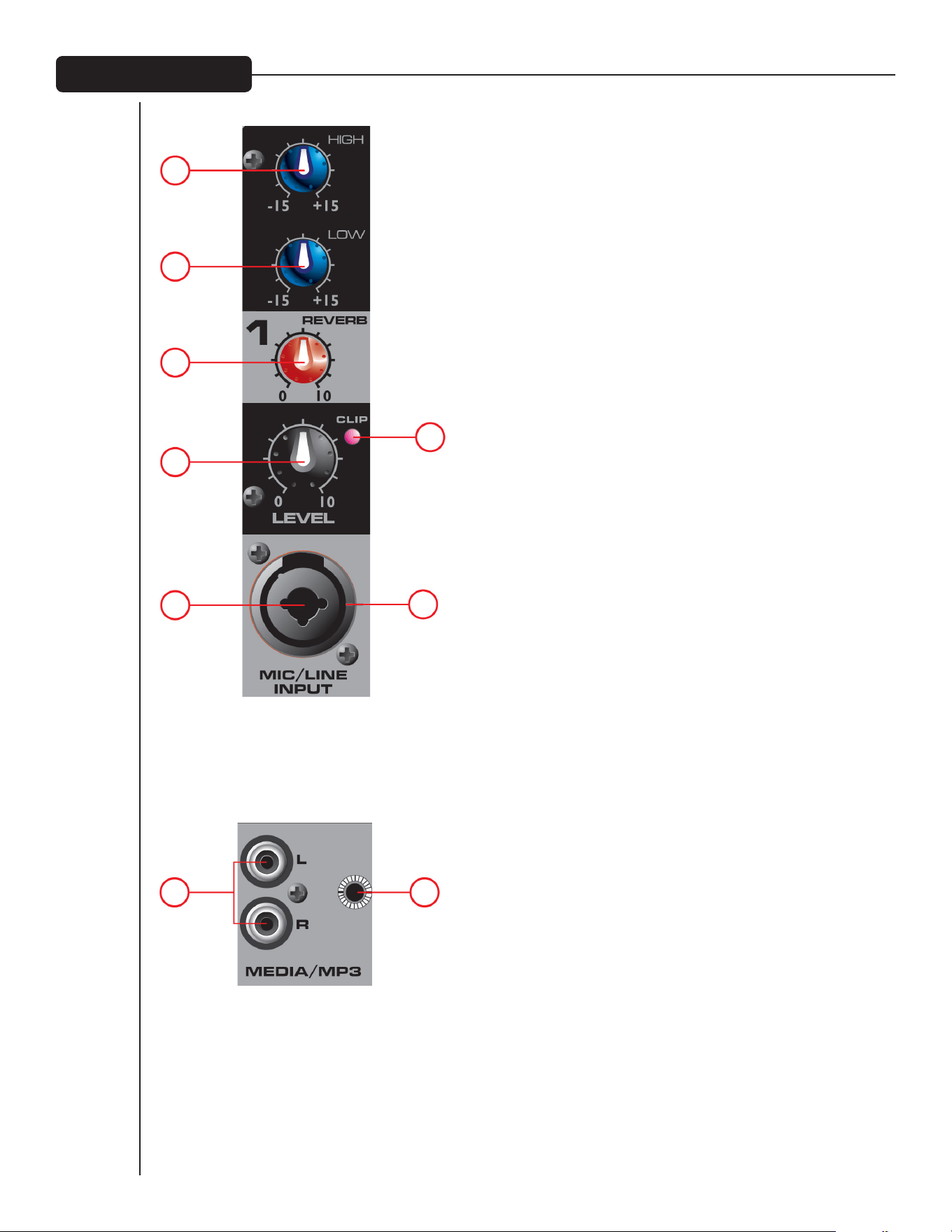
3
(1) HIGH (DISKANTTI) -SÄVYSÄÄTÖ
Aktiivinen äänensävyhallinta (kalteva: ±15 dB) diskanttiäänialueen
tason muuttamiseen.
(2) LOW (BASSO) -SÄVYSÄÄTÖ
Aktiivinen äänensävyhallinta (kalteva: ±15 dB) bassoäänialueen tason
muuttamiseen.
Varoitus: Alaäänialueen liiallinen korostaminen lisää tehon kulutusta
ja kasvattaa kaiuttimien vahingoittumisen mahdollisuutta.
(3) REVERB -SÄÄDIN
Tätä käytetään efektiväylän lähtösäätimenä. Se säätää syöttö-
signaaliin lisätyn kaiun määrää.
(4) LEVEL -SÄÄDIN
Kunkin kanavan tasosäädin lähettää signaalin miksauksen
master-väylään. Tyypillinen käyttötaso on 4–8 (riippuen laitteista),
mutta tason tulee olla master-tasoa alempi. Muista, että tämä
toimii esivahvistimen tavoin, joten jos käytät äänenvoimakkuuden
säädöllä varustettua laitetta (ts. kasetti- tai CD-soitinta), äänenvoi-
makkuustasot tulee kohdistaa säätämällä kunkin laitteen
tasosäätimiä.
(5) CLIP -LED
Ilmaisee, milloin signaalitaso on 3 dB päässä leikkaamisesta.
(6) 3-NASTAINEN (XLR) MATALAN IMPEDANSSIN
MIKROFONITULO, MICROPHONE INPUT
Tämä tulo tyypillisille, balansoiduille, matalan impedanssin
mikrofoneille. Se syöttää automaattisesti 15V phantom-virran
kondensaattorimikrofoneille tai aktiivisille DI-bokseille. Tulon
impedanssi on 1 kilo-ohmi. Liittimen johdot ovat seuraavat: Nasta
1=runko; Nasta 2=positiivinen (kuuma); Nasta 3=negatiivinen
(kylmä).
(7) 1/4" LINE
1/4" linjatuloliitännällä voidaan kytkeä kanavatuloon linjatasoisia
lähteitä. Linjatuloa käytetään yleensä kosketinsoittimien
tai CD-soittimien kaltaisille lähteille, ja sitä voidaan käyttää
langattomien mikrofonivastaanottimien korkean tason lähdön
kassa. Kun tämä tulo on käytössä, XLR-mikrofonitulo kytketään
pois.
(8A) JA (8B) MEDIA-TULO
Nämä tulot, RCA (8A) ja 1/8" (8B) ovat stereotuloja, joihin voidaan
kytkeä MP3-soitin, CD-soitin, kasettinauhuri tai muu vastaava
laite.
Mikrofoni-/Linjatulo
1
2
3
4
5
67
8A 8B
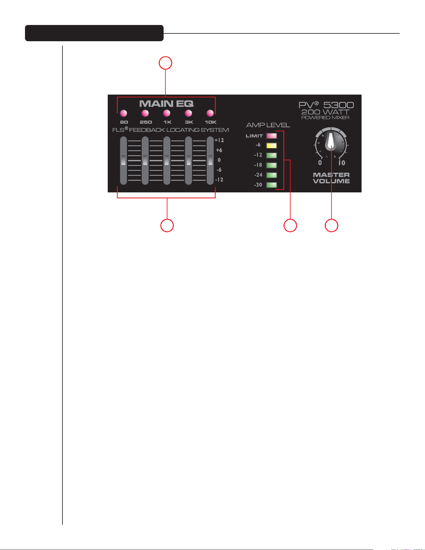
4
8
7
9 10
(7) FLS
®
FEEDBACK LOCATING SYSTEM -JÄRJESTELMÄ
Patentoitu FLS Feedback Locating System -järjestelmä on nopea ja helppo tapa poistaa kierto järjestelmästä. Jos
kiertoa esiintyy, LED syttyy ko. taajuusalueen kohdalla ja ilmaisee, mitä liukusäädintä tulee käyttää. Laske ko.
säädintä hitaasti, kunnes kierto häviää. LED palaa muutaman sekunnin ajan vielä kierron hävittyä. On normaalia,
että valot syttyvät ajoittain esityksen aikana. Tämä ei välttämättä tarkoita, että ääni kiertää.
(8) GRAAFINEN EQ
5-kanavaisessa EQs-korjaimessa on 12dB vaimennus tai tehostus. EQs -säätimillä tehdään pieniä säätöjä
kokonaismiksaukseen; niitä tulee käyttää säästeliäästi.
(9) AMP LEVEL -LED-PORTAIKKO
Nämä LED-valot ilmaisevat päätevahvistimelle menevän signaalitason. Ylin LED tarkoittaa, että raja LIMIT on
saavutettu, ja että PV 5300:n sisään rakennettu käänteentekevä DDT
™
-kaiutinsuojaus aktivoituu ja maksimoi
vahvistimen tehon ilman säröytymisen vaaraa.
(10) MASTER VOLUME
Master-tasosäädin päämiksaukselle ja aktiivimikserin äänenvoimakkuussäädin.
Taajuuskorjain / Äänenvoimakkuus

5
11
14 15 16
12 13
(11) FOOTSWITCH
Tähän 1/4" liitäntään voidaan kytkeä 1/4" jalkakytkin (Peaveyn
osanumero 03051000), joka on suunniteltu sammuttamaan kaikkien
kanavien kaikuefekti.
(12) REC OUT
Tämä RCA-lähtö antaa signaalin CD-tallentimen, stereokasetti-
soittimen tai muun tallennuslaitteen tuloihin.
HUOMAA: Älä kytke samaa laitetta sekä Rec Out- että
Media Input (8A/8B) -liittimiin samanaikaisesti; tästä
voi seurata silmukka, joka voi aiheuttaa kiertoa ja
vahingoittaa järjestelmääsi.
(13) MAIN-LÄHTÖ
Tämä 1/4" liitin antaa signaalin päämiksauksesta (graafisen EQ-
korjaimen jälkeen) ulkoiselle päätevahvistimelle.
(14) MUTE -LED
Kun tämä LED palaa, se ilmaisee, että kanavat 1-4 on mykistetty,
eivätkä ne välitä signaalia päätevahvistimelle.
(15) MUTE -KYTKIN
Tämän painikkeen painaminen mykistää kanavat 1-4 ja estää signaalin
siirron päätevahvistimelle. Tämä painike ei vaikuta kanavaan 5. Toiminto
on kätevä pidettäessä taukoja esitysten välillä, jolloin musiikkia
voidaan soittaa järjestelmän läpi, vaikka linja- ja mikrofonikanavat on
mykistetty.
(16) MASTER REVERB
Kaikuefektin yleistaso vastaavilla kanavilla.

6
17
18
19
21
20
Takapaneeli
(17) VIRTAKYTKIN
Tämä on päävirtakytkin.
(18) VERKKOVIRTATULO:
Tämä liitin on IEC-virtajohdolle, joka syöttää laitteeseen AC-virtaa.
Kytke laitteen virta kytkemällä virtajohto tähän liittimeen. Väärän
verkkojännitteen käytöstä voi seurata laitteen vaurioituminen.
(Katso laitteessa olevaa verkkojännitteen merkintää)
Älä koskaan katkaise maadoitusjohdinta. Se on tarkoitettu
turvallisuutesi takaamiseen. Laitteen saa liittää vain maadoitettuun
pistorasiaan.
Sähköisku- ja tulipalovaaran välttämiseksi tulee aina varmistaa,
että vahvistin ja siihen kytketyt laitteet on maadoitettu.
NOTE: FOR U.K. ONLY
As the colors of the wires in the mains lead of this apparatus
may not correspond with the colored markings identifying the
terminals in your plug, proceed as follows:
(1) The wire which is colored green and yellow must be connected
to the terminal which is marked by the letter E, or by the Earth
symbol, or colored green or green and yellow. (2) The wire which
is colored blue must be connected to the terminal which is marked
with the letter N, or the color black. (3) The wire which is colored
brown must be connected to the terminal which is marked with
the letter L, or the color red.
(19) FUSE
Tämä on verkkojännitteen pääsulake. Vaihda sulake vain tyypiltään ja
arvoiltaan täsmälleen samanlaiseen. Jos sulake palaa uudelleen, älä
vaihda sitä suurempaan. Vie laite valtuutettuun Peavey-huoltoon.
HUOMAA: Jos verkkojännite muuttuu, myös sulake on vaihdettava
soveltumaan jännitteeseen, johon vaihdat.
(20) JÄNNITTEEN VALINTAKYTKIN
Tällä kytkimellä käyttäjä voi valita 115VAC / 60Hz tai 230VAC /
50Hz. Jotta jännitteen valitsinta voi käyttää, on ensin avattava ja
poistettava kytkintä suojaava muovikuori. Jännitteen vaihtamisen
jälkeen aseta muovikuori takaisin, jotta varmistetaan, ettei
jännitetasoa muuteta vahingossa.
HUOMAA: Sulake TÄYTYY vaihtaa oikeaan arvoon valitsemallesi
jännitteelle. Katso oikea arvo mikserin takana olevasta merkinnästä.
(21) SPEAKER OUTPUTS -LIITTIMET
Nämä ovat kaksijohtimisia 1/4" kaiutinlähtöjä. Kummankin
vähimmäisimpedanssi on 4 ohmia. Voit kytkeä kumpaankin lähtöön
joko yhden 4 ohmin kaiuttimen, yhden 8 ohmin kaiuttimen tai kaksi
8 ohmin kaiutinta. Älä käytä alle ilmoitetun minimi-impedanssin.
Varmista paras tehonsiirto käyttämällä kaiutinten kytkemiseen
kaiutinkaapeleita, ei soitinkaapeleita. Suosittelemme vähintään
1 mm
2
kaiutinjohtoa.
NOTE: Before changing
voltage or fuse value,
make sure unit is
disconnected from AC
power.

Ominaisuudet ja tiedot voivat muuttua ilman eri ilmoitusta.
Peavey Electronics Corporation • 5022 Hartley Peavey Drive • Meridian, MS • 39305
(601) 483-5365 • FAX (601) 486-1278 • www.peavey.com • EX 000130 • ©2011
TULON HERKKYYS:
Mic In -tulosta täyteen tehoon päätevahvistimessa. Master Volume norm.
Täysi Nimellinen
-48 dBu -28 dBu
Line In -tulosta täyteen tehoon päätevahvistimessa. Master Volume norm.
Täysi Nimellinen
-18 dBu +3 dBu
KANAVA-EQ:
Kalteva EQ
Matala EQ 80 Hz ±15 dB
Korkea EQ 12 kHz ±15 dB
CLIP -LED:
Leikkaus-LED syttyy 3dB ennen leikkausta.
TAAJUUSVASTE:
Kaikki säätimet nimellisasennoissaan (lukittu)
Mic – Main 30 Hz – 20 kHz +0, -1 dB
Line – Main 20 Hz – 30 kHz +0, -1 dB
Mic – Amp 50 Hz – 20 kHz +0, -3 dB
Line – Amp 40 Hz – 20 kHz +0, -3 dB
KOHINA:
Main = Main-linjatulo, 22 - 22kHz suodatin
Amp 1 = Vahvistinlähtö, kuormitettu 4 ohmiin, AP
AUX-0025 -vahvistinsuodattimen kautta
Kaikki säätimet alhaalla.
Main <-95 dBu
Amp 1 <-70 dBu
Master Volume nimellinen
Main <-90 dBu
Amp 1 <-67 dBu
KOKONAISSÄRÖ:
Kaikki säätimet nimellisasennoissaan
<0,01% @ päälinjatulossa, -30 dBu mikrofonitulossa
<0,09% @ amp 1, lähtö säädettynä 45 W
Kaikki säätimet nimellisasennoissaan
<0,005% @ päälinjalähdössä, +4 dBu linjatulossa
<0,08% @ amp 1, lähtö säädettynä 45 W
MASTER EQ:
80 Hz +/-12 dB
250 Hz +/-12 dB
1 kHz +/-12 dB
3 kHz +/-12 dB
10 kHz +/-12 dB
MITTARINAUHA:
RAJA
-6 dB
-12 dB
-18 dB
-24 dB
-30 dB
VAHVISTIMEN RAJOITIN:
Rajoittaa vahvistintehon juuri ennen leikkausta. Rajoitin pitää vahvistintehon
ilman leikkausta, ja se voidaan ohjata jopa 18 dB yli enimmäistehon.
VAHVISTIMEN LÄHTÖTEHO:
120VAC
Molemmat kanavat kuormattuna 8 ohmiin: 30 W RMS / kanava
60 W Peak / kanava
Molemmat kanavat kuormattuna 4 ohmiin: 50 W RMS / kanava
100 W Peak / kanava
TEHOVAATIMUKSET:
USA: 120VAC 50/60Hz 40 W nimellinen
Kansainväliset mallit: 230VAC 50/60Hz 40 W nimellinen
KOKO:
Mitat: K x L x S
9” x 14” x 9”
PAINO: 14 lbs.
Tekniset tiedot
FCC:N SÄÄNTÖJEN ALAKOHTA J TÄMÄ LAITE NOUDATTAA FCC-SÄÄNTÖJEN
OSAA 15. TOIMINTAA KOSKEVAT SEURAAVAT EHDOT: (1) TÄMÄ LAITE EI SAA
AIHEUTTAA HAITALLISIA HÄIRIÖITÄ, JA (2) TÄMÄN LAITTEEN TULEE OTTAA
VASTAAN HÄIRIÖT, MUKAAN LUKIEN VIRHEELLISTÄ TOIMINTAA AIHEUTTAVAT.

2
PV
®
5300
Powered Mixer
Gratulerar till inköpet av en PV ”powered mixer” från Peavey
®
. Peavey PV 5300 är en allt-i-ett ”powered mixer”
som ger upp till fyra kombinerade XLR- och 1/4-tumsingångar med Peaveys förstklassiga förförstärkare och
200 watt toppeffekt för kristallklar ljudåtergivning. Peavey PV 5300 använder exklusiva och patenterade
funktioner för att hjälpa till att förbättra röstens ton och renhet. Vårt patenterade FLS
®
(Feedback Locating
System) identifierar snabbt och enkelt rundgång och tar bort den. Inbyggt reverb som kan skötas med fotpedal
kompletterar den redan funktionsfyllda enheten. Du kan ansluta nästan vad som helst till denna mångsidiga mixer
via de inbyggda 1/4-tums-, RCA- och 1/8-tumsingångarna.
Innan du börjar använda din ”powered mixer” är det viktigt att du kontrollerar att produkten får
korrekt växelspänning. Förstärkarens rätta spänning står tryckt bredvid IEC-nätsladden på enhetens
bakpanel.
Funktioner:
• FLS
®
(Feedback Locating System)
• Inbyggt digitalt reverb
• Kombinerade XLR- och 1/4 -tumsingångar
• Fembands grafisk equalizer med FLS
®
• Master mute för kanalerna 1-4
• Fotpedalsstyrda effekter
• RCA, 1/8-tums mediaingång
• Dubbel effektförstärkarsektion
• RCA inspelningsutgångar
• Mätarbro med lysdioder
• Subsoniskt filter i effektförstärken
VENTILATION: För att få ordentlig ventilation krävs cirka 15, 5 cm fritt utrymme runt alla sidor.
Svenska
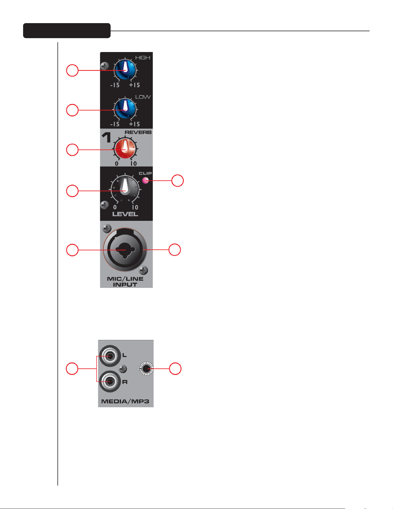
3
(1) TONKONTROLL HIGH (DISKANT)
En aktiv tonkontroll (shelving-typ ±15 dB) som varierar nivån på
högfrekvensområdet.
(2) TONKONTROLL LOW (BAS)
En aktiv tonkontroll (shelving-typ ±15 dB) som varierar nivån på
lågfrekvensområdet.
Obs: Överdriven höjning av låga frekvenser ger högre strömförbrukning
och ökar risken för skador på högtalarna.
(3) REVERBKONTROLL
Används som sändningskontroll till effektbussen. Kontrollerar
mängden reverb som läggs på ingångs¬signalerna.
(4) LEVELKONTROLL (NIVÅ)
Level-kontrollen för respektive kanal sänder signalen
till mastermixbussen. Normal inställning är mellan 4 och 8
(beroende på de inkopplade apparaterna) men ska vara lägre än
masternivån. Kom ihåg att detta fungerar som en förförstärkare,
så om du använder en apparat med utgångsvolymkontroll (dvs.
band- eller CD-spelare) måste du matcha nivåerna genom att
justera nivåkontrollerna på respektive enhet.
(5) LYSDIOD FÖR CLIP (KLIPPNING)
Indikerar när signalnivån ligger inom 3 dB från att klippas.
(6) MICROPHONE INPUT (MIKROFONINGÅNG), 3 STIFT (XLR)
LÅGIMPEDANS
Denna ingång är för typiska balanserade lågimpedans-
mikrofoner. Den tillhandahåller automatiskt 15 V fantom ström
för kondensator mikrofoner eller aktiva direktboxar. Den har en
ingångsimpedans på 1 kohm. Anslutningen är kopplad så här:
stift 1=hylsa; stift 2=positiv (strömförande); stift 3=negativ (ej
strömförande).
(7) 1/4-tums LINE
1/4-tums linjeingången används för anslutning av linjenivåkällor
till kanalingången. Linjeingången används typiskt för källor som
klaviatur och CD-spelare och kan användas med högnivåutsignalen
från trådlösa mikrofonmottagare. När denna ingång används
kopplas XLR-mikrofoningången bort.
(8A) OCH (8B) MEDIAINGÅNG
Dessa ingångar, RCA (8A) och 1/8–tums (8B), accepterar
stereoingång från utgången från MP3-spelare, CD-spelare,
kassettdäck eller andra liknande enheter.
Mikrofon-/linjeingång
1
2
3
4
5
67
8A 8B
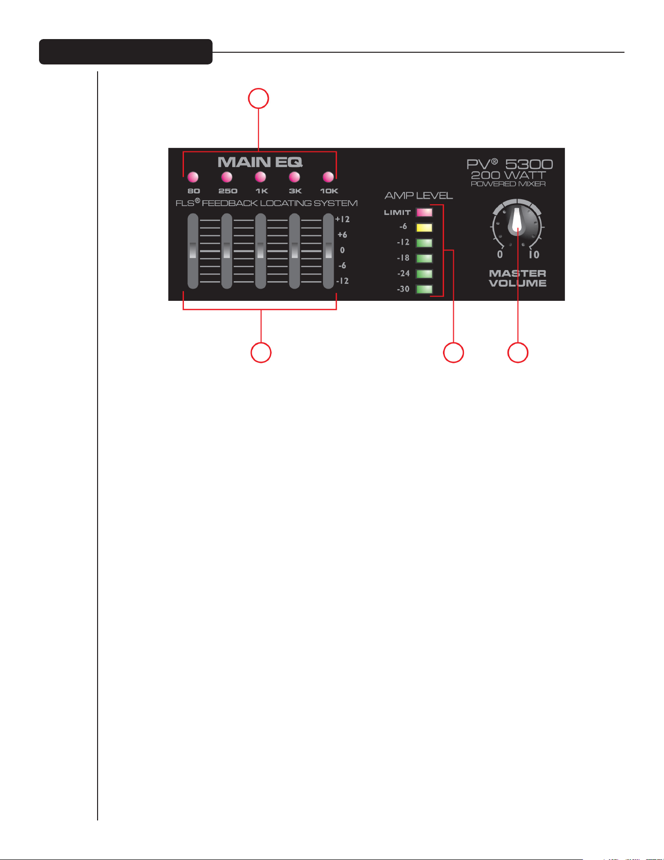
4
8
7
9 10
(7) FLS
®
FEEDBACK LOCATING SYSTEM
Det patenterade FLS (Feedback Locating System) är ett snabbt och enkelt sätt att ta bort rundgång från
systemet. När det uppstår rundgång tänds lysdioden ovanför skjutreglaget till det frekvensband där rundgången
uppstått för enkel justering. Sänk långsamt skjutreglaget tills rundgången är borta. Lysdioden fortsätter lysa
ett par sekunder efter det att rundgången försvunnit. Det är normalt att lysdioderna tänds då och då under ett
framträdande. Detta betyder inte nödvändigtvis att rundgång har uppstått.
(8) GRAFISK EQ
Dessa 5-bands EQ är konstruerade för att kapa eller höja 12 dB. Dessa EQ används för att göra mindre justeringar
av den totala mixen och bör användas sparsamt.
(9) LYSDIODSTEGE FÖR AMP LEVEL (FÖRSTÄRKARNIVÅ)
Dessa lysdioder indikerar signalnivån som går till effektförstärkaren. Den översta lysdioden indikerar LIMIT
och aktivering av vår revolutionära DDT
™
-krets för högtalarskydd, som är inbyggd i PV 5300 och aktiveras
automatiskt för maximering av effektförstärkaren utan att du behöver oroa dig för distorsion.
(10) MASTERVOLUME (HUVUDVOLYM)
Huvudnivåkontrollen för huvudmixen och den totala volymen för din ”powered mixer”.
Huvud-EQ / Mastervolym

5
11
14 15 16
12 13
(11) FOOTSWITCH (FOTPEDAL)
Detta 1/4-tums uttag tar emot en 1/4-tums fotpedal (Peavey
artikelnummer 03051000) som är konstruerad för att stänga av
reverbeffekten på alla kanaler.
(12) REC OUT
Denna RCA-utgång ger en signal till inspelningsingångar på
CD-inspelare, stereokassettdäck eller andra inspelningsenheter.
OBS: Anslut inte en och samma enhet till både Rec Out
och mediaingången (8A/8B) samtidigt, det kan skapa
en loop som kan orsaka kraftig rundgång som kan
skada ditt system.
(13) MAIN UT
Detta 1/4-tumsuttag ger en signal från huvudmixen (efter den
grafiska EQ:n) till en extern effektförstärkare.
(14) LYSDIOD FÖR MUTE
När denna lysdiod lyser visar den att kanalerna 1-4 är dämpade
och inte sänder någon signal till effektförstärkaren.
(15) OMKOPPLARE FÖR MUTE
Om du trycker in den här knappen dämpar du kanalerna 1-4
och hindrar signalen att gå till effektförstärkaren. Den här
knappen påverkar inte kanal 5. Den här funktionen är praktisk
för pauser mellan uppträdanden, det går att spela musik genom
ljudsystemet medan linje-/mikrofonkanalerna är dämpade.
(16) MASTER REVERB
Totala nivån på reverbeffekten på motsvarande kanaler.
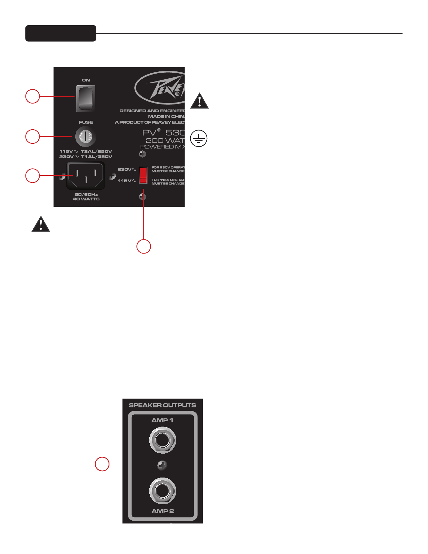
6
17
18
19
21
20
Bakre panelen
(17) STRÖMBRYTARE
Detta är huvudströmbrytaren.
(18) VÄXELSTRÖMSINGÅNG:
Detta är ett honuttag för en IEC-nätkabel, som förser enheten
med växelström. Anslut nätkabeln till detta uttag för att förse
enheten med ström. Om felaktig nätspänning används kan det
orsaka skador på utrustningen. (Se nätspännings¬märkningen
på enheten.)
Bryt aldrig av jordstiftet på någon utrustning. Det sitter där för
din säkerhets skull. Om du använder ett eluttag som saknar
jordstift ska en lämplig jordningsadapter användas, och den
tredje ledningen ska jordas ordentligt.
För att förhindra risken för elstötar eller eldsvåda ska du alltid
se till att förstärkaren och all tillhörande utrustning är ordentligt
jordade.
NOTE: FOR U.K. ONLY
As the colors of the wires in the mains lead of this apparatus
may not correspond with the colored markings identifying the
terminals in your plug, proceed as follows:
(1) The wire which is colored green and yellow must be connected
to the terminal which is marked by the letter E, or by the Earth
symbol, or colored green or green and yellow. (2) The wire
which is colored blue must be connected to the terminal which
is marked with the letter N, or the color black. (3) The wire which
is colored brown must be connected to the terminal which is
marked with the letter L, or the color red.
(19) FUSE (SÄKRING)
Detta är huvudsäkringen för växelspänningen. Byt endast ut mot
en säkring av exakt samma typ och märkning. Om säkringen
fortsätter att utlösas ska du inte sätta i en kraftigare säkring,
lämna istället in enheten till ett av Peaveys servicecenter.
OBS: Om nätspänningen ändras måste även säkringen bytas till
en säkring med motsvarande märkning för den spänning som du
byter till.
(20) SPÄNNINGSVÄLJARE
Med den här omkopplaren kan du välja mellan 115 VAC / 60 Hz
eller 230 VAC / 50 Hz. För att byta spänning måste du först skruva
loss och ta bort plastskyddet som sitter över omkopplaren. När
du har bytt spänning ska du skruva fast plastskyddet igen så att
spänningen inte ändras av misstag.
OBS: Säkringen MÅSTE bytas till en med motsvarande värde för
den spänning du har valt. Se noteringen på baksidan av mixern
för korrekt värde.
(21) SPEAKER OUTPUTS (HÖGTALARUTGÅNGAR)
Detta är 1/4-tums högtalarutgångar med tvåledare. Var och en är
märkt med minimiimpedansen 4 ohm. Du kan ansluta antingen
en 4-ohms, en 8-ohms eller två 8-ohms högtalare till respektive
utgång. Använd inte med lägre impedans än minimiimpedansen.
För bästa resultat ska du använda högtalarkablar och inte
instrumentkablar för att ansluta högtalarna. Vi rekommenderar
att du använder högtalarkablar av minst 18 gauge (1,02 mm)
tjocklek.
OBS: Innan du ändrar
värdet på spänningen eller
säkringen måste enheten
vara bortkopplad från
strömkällan.

Ändringar i funktioner och specifikationer förbehålles utan meddelande.
Peavey Electronics Corporation • 5022 Hartley Peavey Drive • Meridian, MS • 39305
(601) 483-5365 • FAX (601) 486-1278 • www.peavey.com • EX 000130 • ©2011
INGÅNGSKÄNSLIGHET:
Mikrofon in till full styrka på effektförstärkaren. Mastervolym nom.
Full Nominell
-48 dBu -28 dBu
Linje in till full styrka på effektförstärkaren. Mastervolym nom.
Full Nominell
-18 dBu +3 dBu
KANAL EQ:
Shelving EQ
Låg EQ 80 Hz ±15 dB
Hög EQ 12 kHz ±15 dB
LYSDIOD FÖR CLIP (KLIPPNING):
Lysdioden för klippning tänds 3 dB innan klippning.
FREKVENSÅTERGIVNING:
Alla kontroller nominella (spärrade)
Mikrofon till main 30 Hz – 20 kHz +0, -1 dB
Linje till main 20 Hz – 30 kHz +0, -1 dB
Mikrofon till förstärkare 50 Hz – 20 kHz +0, -3 dB
Linje till förstärkare 40 Hz – 20 kHz +0, -3 dB
BRUS:
Main = Main linjeutgång, 22 - 22kHz filter
Förstärkare 1 = Förstärkarutgång, belastad vid 4 ohm, genom AP
AUX-0025 kopplingsförstärkare filter
Alla kontroller helt nere.
Main <-95 dBu
Förstärkare 1 <-70 dBu
Mastervolym nominell
Main <-90 dBu
Förstärkare 1 <-67 dBu
THD:
Alla kontroller nominella
<0,01 % vid main linjeutgång, –30 dBu i mikrofoningång
<0,09 % vid förstärkare 1 med utsignal justerad till 45 watt
Alla kontroller nominella
<0,005 % vid main linjeutgång, +4 dBu i linjeingång
<0,08 % vid förstärkare 1 med utsignal justerad till 45 watt
MASTER EQ:
80 Hz +/-12 dB
250 Hz +/-12 dB
1 kHz +/-12 dB
3 kHz +/-12 dB
10 kHz +/-12 dB
MÄTARUPPSTÄLLNING:
LIMIT
-6 dB
-12 dB
-18 dB
-24 dB
-30 dB
FÖRSTÄRKARLIMITER:
Begränsar förstärkarens uteffekt precis innan klippning. Begränsaren
håller förstärkarens uteffekt utan att klippa och kan drivas upp till 18
dB över maximal uteffekt.
FÖRSTÄRKARENS UTEFFEKT:
120VAC
Båda kanalerna belastade vid 8 ohm: 30 watt RMS per kanal
60 watt peak per kanal
Båda kanalerna belastade vid 4 ohm: 50 watt RMS per kanal
100 watt peak per kanal
EFFEKTBEHOV:
Inhemsk: 120 VAC 50/60 Hz 40 watt nominellt
Export: 30 VAC 50/60 Hz 40 watt nominellt
STORLEK:
Mått: H x B x D
22,9 x 35,6 x 22,9 cm
VIKT: 6,35 kg
Specifikationer
KAPITEL J I FCC-BESTÄMMELSERNA. DENNA APPARAT ÖVERENSSTÄMMER MED
DEL 15 I FCC-REGLERNA. ANVÄNDNINGEN ÄR UNDERSTÄLLD FÖLJANDE TVÅ
VILLKOR (1) DENNA ENHET FÅR INTE ORSAKA SKADLIGA STÖRNINGAR, OCH (2)
DENNA ENHET MÅSTE ACCEPTERA ALLA MOTTAGNA STÖRNINGAR, INKLUSIVE
STÖRNINGAR SOM KAN ORSAKA OÖNSKAD DRIFT.

2
Mixer potenziato
PV
®
5300
Congratulazioni per aver comprato il vostro nuovo mixer potenziato PV di Peavey. Il Peavy PV 5300 è un mixer
potenziato tutto in uno, che fornisce fino a 4 combinazioni XLR ed entrate da 1/4" usando preamplificatori
microfonici Peavey di qualità superiore e 200 watt di potenza di picco per una riproduzione del suono chiara e
cristallina. Il Peavey PV 5300 utilizza caratteristiche esclusive e brevettate per aiutare con precisione a migliorare
il tono e la chiarezza delle voci. Il nostro Impianto di Localizzazione del Ritorno FLS
®
, brevettato e rivoluzionario,
identifica ed elimina il ritorno velocemente e con facilità. Il riverbero incorporato, attivabile con i piedi, completa
l’unità già ricca di funzioni. Connettete quasi qualsiasi cosa a questo mixer versatile tramite i mini jack integrati
da 1/4", RCA e da 1/8".
Prima che cominciate a utilizzare il vostro mixer alimentato, è molto importante che vi assicuriate che
il prodotto sia alimentato con la giusta tensione AC. Potete trovare la tensione adatta per il vostro
amplificatore stampata vicino al cavo di rete IEC (alimentazione) sul pannello posteriore dell’unità.
Caratteristiche:
• FLS
®
Impianto di Localizzazione del Ritorno
• Riverbero digitale integrato
• Combinazioni XLR e jack di entrata da 1/4"
• Equalizzatore grafico a 5 bande con FLS
®
• Muto del master per i canali 1-4
• Esclusione degli effetti tramite azionamento con un piede
• Ingresso RCA, 1/8" per sorgenti
• Sezione amplificatore a doppia alimentazione
• Uscite RCA di registrazione
• Meterbridge a LED
• Filtraggio subsonico per amplificatore di potenza
VENTILAZIONE: Per una corretta ventilazione, lasciate uno spazio di 6" (15,5 cm) su tutti i lati.
Italiano
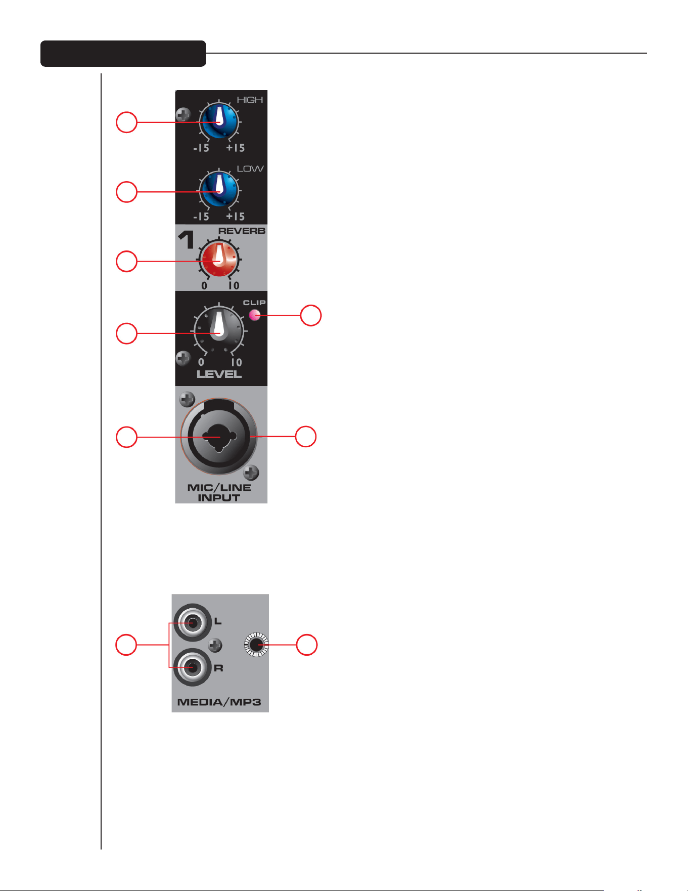
3
(1) CONTROLLO TONI HIGH (ACUTI)
Un controllo attivo dei toni (tipo di shelving: ±15 dB) che varia il
livello dell’alta gamma di frequenza.
(2) CONTROLLO TONI LOW (BASSI)
Un controllo attivo dei toni (tipo di shelving: ±15 dB) che varia il livello
della bassa gamma di frequenza.
Attenzione: un’eccessiva amplificazione della bassa frequenza causa
un maggiore consumo di elettricità e aumenta la possibilità di danni
agli altoparlanti.
(3) CONTROLLO REVERB
Questo viene utilizzato come un controllo di invio al bus degli
effetti. Controlla la quantità di riverbero aggiunta ai segnali in
ingresso.
(4) CONTROLLO LEVEL
Il controllo del livello per ogni canale invia il segnale al bus
di missaggio principale. Il funzionamento tipico è tra 4 e 8 (a
seconda dei dispositivi in ingresso) ma dovrebbe essere inferiore
al livello del master. Vi preghiamo di ricordarvi che funziona come
un preamplificatore, perciò se state utilizzando un apparecchio
che ha un controllo di uscita del volume (cioè un mangianastri
o un lettore CD) avrete bisogno di far corrispondere i livelli
regolando i controlli del livello su ogni unità.
(5) LED CLIP
Indica quando il livello del segnale è entro i 3 dB di distorsione.
(6) MICROPHONE INPUT A BASSA IMPEDENZA A 3 SPINE (XLR)
Questo ingresso è per microfoni tipicamente bilanciati e a
bassa impedenza. Fornirà automaticamente un’alimentazione
phantom a 15V per microfoni a condensatore o per casse
attive dirette. Ha un’impedenza di ingresso pari a 1k ohm.
Il connettore è collegato come: Spina 1=schermo; Spina
2=positivo (fase); Spina 3= negativo (controfase).
(7) LINE DA 1/4"
Il connettore di linea in ingresso da 1/4" viene utilizzato per
connettere sorgenti al livello di linea all’ingresso del canale.
L’ingresso di linea viene utilizzato tipicamente per sorgenti come
tastiere e lettori CD e può essere utilizzato con l’uscita ad alto
livello di ricevitori microfonici senza fili. Quando viene utilizzato
questo ingresso, l’ingresso microfonico XLR viene disconnesso.
INGRESSO MEDIA (8A) E (8B)
Questi ingressi, RCA (8A) e da 1/8" (8B) accettano un ingresso
stereo di un lettore MP3, un lettore CD, un mangianastri o un
apparecchio simile.
Ingresso Microfono/ Linea
1
2
3
4
5
67
8A 8B

4
8
7
9 10
(7) FLS
®
FEEDBACK LOCATING SYSTEM
Il FLS Feedback Locating System brevettato è un modo semplice e veloce di eliminare il ritorno dall’impianto.
Quando si verifica il ritorno, il LED che corrisponde alla banda di frequenza che causa la retroilluminazione si
illuminerà sul potenziometro che andrà regolato. Abbassate lentamente quel potenziometro finché il ritorno
non scompare. Il LED rimarrà illuminato per alcuni secondi dopo la scomparsa del ritorno. È normale che
occasionalmente le luci si accendano durante un’esecuzione. Questo non significa necessariamente che si stia
verificando un ritorno.
(8) EQ GRAFICO
Questi EQs a cinque bande sono progettati per il taglio o l’amplificazione a 12 dB. Questi EQs vengono utilizzati
per effettuare regolazioni di minore importanza sul mix generale e andrebbero utilizzati con moderazione.
(9) SCALA A LED AMP LEVEL
Questi LED indicano il livello di segnale che arriva all’amplificatore di potenza. Il LED in alto indica il LIMIT e
l’attivazione del nostro rivoluzionario circuito di protezione degli altoparlanti DDT
™
, integrato nel PV 5300 e che
si attiva automaticamente per massimizzare l’amplificatore di potenza senza temere una distorsione.
(10) MASTERVOLUME
Il controllo del livello del master per il mix principale e il volume generale del mixer alimentato.
EQ principale / Volume del Master

5
11
14 15 16
12 13
(11) FOOTSWITCH
Questo jack da 1/4" accetta un footswitch da 1/4" (numero di codice
Peavey 03051000) progettato per eliminare l’effetto Riverbero su tutti
i canali.
(12) REC OUT
Questa uscita RCA fornisce un segnale agli ingressi di registrazione di
un registratore di CD, un mangiacassette stereo o un altro apparecchio
di registrazione.
NOTA: Non connettete simultaneamente un singolo
apparecchio al Rec Out e all’ingresso Sorgenti (8A/8B),
questa configurazione potrebbe creare un circuito che
potrebbe causare un grave ritorno, che potenzialmente
potrebbe danneggiare il vostro impianto.
(13) USCITA MAIN
Questo jack da 1/4" jack fornisce un segnale dal mix principale (dopo
l’equalizzatore grafico) per un amplificatore di potenza esterno.
(14) LED PER IL MUTE
Quando questo LED si illumina indica che i canali 1-4 vengono
esclusi e non passano il segnale all’amplificatore di potenza.
(15) INTERRUTTORE MUTE
Premendo questo tasto si escludono i canali 1-4 evitando che il
segnale passi all’amplificatore di potenza. Il tasto non influenza
il canale 5. Questa funzione è utile tra un’esecuzione e un’altra,
permettendo di riprodurre musica tramite l’impianto audio
escludendo i canali linea/microfono.
(16) REVERB DEL MASTER
Livello generale dell’effetto Riverbero sui canali corrispondenti.
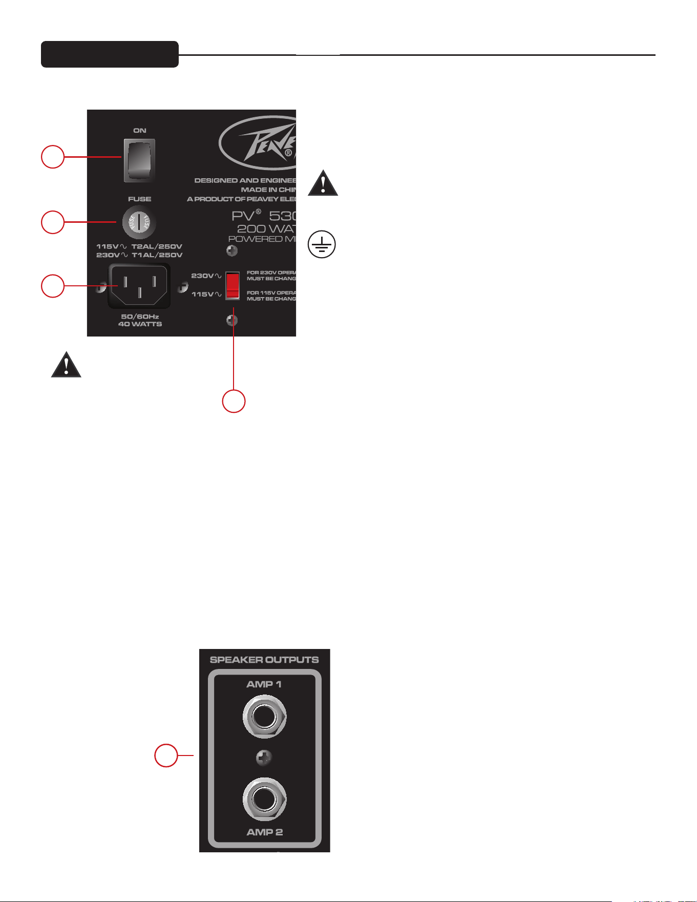
6
17
18
19
21
20
Pannello posteriore
(17) INTERRUTTORE DI ALIMENTAZIONE
Questo è l’interruttore dell’alimentazione principale.
(18) PRESA DELL’ALIMENTAZIONE AC:
Questa è una presa per un cavo di alimentazione IEC, che
fornisce alimentazione AC all’unità. Connettete il cavo di linea
a questo connettore per fornire alimentazione all’unità Se viene
utilizzata una tensione di linea inadeguata si può danneggiare
l’apparecchiatura. (Vedi l’etichetta di tensione sull’unità).
Non interrompete mai la spina della massa su qualsiasi
apparecchiatura. Essa viene fornita per la vostra sicurezza. Se la
presa non ha una spina della massa bisognerebbe utilizzare un
adattatore di massa adatto e il terzo filo andrebbe messo a terra
adeguatamente.
Per prevenire il rischio di scossa o il pericolo di incendio
assicuratevi sempre che l’amplificatore e tutta l’apparecchiatura
associata siano messi a terra in maniera adeguata.
NOTE: FOR U.K. ONLY
As the colors of the wires in the mains lead of this apparatus
may not correspond with the colored markings identifying the
terminals in your plug, proceed as follows:
(1) The wire which is colored green and yellow must be connected
to the terminal which is marked by the letter E, or by the Earth
symbol, or colored green or green and yellow. (2) The wire
which is colored blue must be connected to the terminal which
is marked with the letter N, or the color black. (3) The wire which
is colored brown must be connected to the terminal which is
marked with the letter L, or the color red.
(19) FUSE
Questo è il fusibile di sicurezza principale per la tensione di linea
AC. Se il fusibile continua ad aprirsi, non sul fusibile . Portate
l’unità a un centro di assistenza autorizzato Peavey.
NOTA: Se la tensione di alimentazione AC è cambiata, anche il
fusibile va cambiato con un campo appropriato per la tensione
alla quale state passando.
(20) INTERRUTTORE PER LA SELEZIONE DELLA SELEZIONE
Questo interruttore permette all’utente di scegliere tra 115VAC /
60Hz e 230VAC / 50Hz. Per cambiare il selettore della tensione,
dovete prima svitare e rimuovere il coperchio di plastica che
protegge l’interruttore. Dopo aver cambiato la tensione, vi
preghiamo di rimettere il coperchio di plastica per assicurare che
il livello di tensione non venga modificato inavvertitamente.
NOTA: Il fusibile DEVE essere cambiato con uno del valore
appropriato affinché corrisponda alla tensione che avete scelto.
Vi preghiamo di leggere la nota sul retro del mixer per individuare
il valore corretto.
(21) SPEAKER OUTPUTS
Queste sono uscite degli altoparlanti, a due conduttori, da 1/4".
Ognuna ha un valore di impedenza minima di 4ohm. Potete
connettere o un altoparlante da 4 ohm, o uno da 8 ohm o due da
8 ohm a ogni uscita. Non operate al di sotto del valore minimo di
impedenza. Per il massimo trasferimento di potenza, assicuratevi
di utilizzare i cavi dell’altoparlante e non i cavi dello strumento
per connettere gli altoparlanti. Raccomandiamo l’utilizzo di un
filo dell’altoparlante da 18 gauge o superiore.
NOTA: Prima di cambiare
il valore della tensione o
dei fusibili, assicuratevi
che l’unità sia disconnessa
dall’alimentazione AC.

Caratteristiche e specifiche soggette a cambiamento senza preavviso.
Peavey Electronics Corporation • 5022 Hartley Peavey Drive • Meridian, MS • 39305
(601) 483-5365 • FAX (601) 486-1278 • www.peavey.com • EX 000130 • ©2011
SENSIBILITA’ IN INGRESSO:
Mic In a piena potenza sull’amplificatore di potenza. Nom Volume Master.
Massimo Nominale
-48 dBu -28 dBu
Linea In a piena potenza sull’amplificatore di potenza. Nom Volume Master.
Massimo Nominale
-18 dBu +3 dBu
EQ CANALE:
Shelving EQ
EQ basso 80 Hz ±15 dB
EQ alto 12 kHz ±15 dB
LED DISTORSIONE:
I LED di distorsione arrivano a 3dB prima della distorsione.
RISPOSTA DI FREQUENZA:
Tutti i controlli sono nominali (arresto)
Da Mic ad Alimentazione 30 Hz – 20 kHz +0, -1 dB
Da Linea ad Alimentazione 20 Hz – 30 kHz +0, -1 dB
Da Mic ad Amplificatore 50 Hz – 20 kHz +0, -3 dB
Dalla Linea ad Amplificatore 40 Hz – 20 kHz +0, -3 dB
RUMORE:
Alimentatore = Uscita della linea di alimentazione, filtro 22 - 22kHz
Amp 1 = Uscita amplificatore, caricata a 4 ohm,
tramite il filtro di commutazione dell’amplificatore AP AUX-0025
Tutti i controlli abbassati del tutto.
Principale <-95 dBu
Amp 1 <-70 dBu
Volume Master nominale
Principale <-90 dBu
Amp 1 <-67 dBu
THD:
Tutti i controlli nominali
<0.01% @ uscita linea alimentazione, -30 dBu nell’ingresso mic
<0.09% @ amp 1 senza ingresso regolato a 45 Watt
Tutti i controlli nominali
<0.005% @ uscita linea alimentazione, +4 dBu ingresso in linea
<0.08% @ amp 1 senza uscita regolata a 45 Watt
EQ MASTER:
80 Hz +/-12 dB
250 Hz +/-12 dB
1 kHz +/-12 dB
3 kHz +/-12 dB
10 kHz +/-12 dB
GAMMA METRICA:
LIMIT
-6 dB
-12 dB
-18 dB
-24 dB
-30 dB
LIMITATORE DI AMPLIFICAZIONE:
Limita la potenza dell’amplificatore appena prima della distorsione.
Il limitatore trattiene la potenza dell’amplificatore senza distorcere e
può essere portato fino a 18 dB oltre l’uscita massima.
POTENZA IN USCITA DELL’AMPLIFICATORE:
120VAC
Entrambi i canali caricati a 8 ohm: 30 Watt RMS per can
60 Watt Picco per can
Entrambi i canali caricati a 4 ohm: 50 Watt RMS per can
100 Watt Picco per can
SPECIFICHE DI ALIMENTAZIONE:
Domestica: 120VAC 50/60HZ 40Watt Nominale
Esterna: 230VAC 50/60HZ 40Watt Nominale
DIMENSIONI:
Dimensioni: A x L x L
9" x 14" x 9"
PESO: 14 lbs.
Specifiche
SOTTOCAPITOLO J DELLE REGOLAMENTAZIONI FCC. QUESTO APPARECCHIO È
CONFORME CON IL CAPITOLO 15 DELLE REGOLAMENTAZIONI FCC. IL FUNZIONAMENTO
DIPENDE DA QUESTE DUE CONDIZIONI (1) QUESTO APPARECCHIO NON PUÒ CAUSARE
INTERFERENZA DANNOSA, E (2) QUESTO APPARECCHIO DEVE ACCETTARE QUALSIASI
INTERFERENZA RICEVUTA, COMPRESA UN’INTERFERENZA CHE PUÒ DETERMINARE UN
FUNZIONAMENTO NON DESIDERATO.

2
PV
®
5300
功放混音器
恭喜您购买了全新的Peavey PV功放混音器,这款Peavey PV 5300是一体化的功放混音器,可提供多达四种
采用高级的Preavey麦克风前置放大器的XLR和1/4英寸输入组合以及200瓦峰值功率,实现清晰的音频再
现。Peavey PV 5300利用其专利功能,能够准确地改善声音的音调和清晰度。而我公司的专利产品—— 革命
性的FLS回馈定位系统,能快速、简易地识别并去除回馈。可脚踏切换、内置回响与功能丰富的设备相辅相
成,可以通过机载1/4英寸、RCA和1/6英寸迷你插孔将任何其他设备连接到这台万能的混音器。
在使用功放混音器前,请确保产品的交流电压正确。用户可从设备背板上IEC线(电源)旁找到印有的
正确的放大器电压。
功能特性:
• FLS回馈定位系统
• 机载数字回响
• XLR和1/4英寸输入组合插孔
• 带FLS
®
的5段图形均衡
• 1-4声道主静音
• 脚踏切换音效降噪
•
RCa、1/8英寸媒体输入
• 双功放单元
• RCa录音输出
• LED表桥
• 功放亚音速过滤
通风:设备各面保持6英寸(15.5厘米)空隙以利于正确通风。
中文

3
(1) HIGH (高音)音调控制
主动音调控制(高频类型:±15 分贝),在高频范围内可变。
(2) LOW (低音)音调控制
主动音调控制(高频类型:±15 分贝),在低频范围内可变。
注意:过度低频增强会导致较大的电耗并增加扬声器损坏的可
能性。
(3) REVERB 控制
用作音效总线的发送控制,可控制添加到输入信号的回响量。
(4) LEVEL 控制
每个声道的音量制向主混音总线发送信号,一般设置在4到8之
间(根据输入设备而定),但应低于主声道音量。请牢记,这项
操作相当于前置放大,如果用户正使用带有音量输出控制的设
备(如磁带机或CD机),则需要调整每个设备上的音量控制与各
音量相匹配。
(5) CLIP LED
当信号大小在削波的3分贝内时亮起。
(6) 3-脚(XLR)低阻抗 MICROPHONE INPUT
该输入一般用于平衡式、低阻抗麦克风,可自动为电容式麦克
风或有源直驳盒提供15伏幻电,输入阻抗为1欧姆。连接孔连
线为:管脚1 = 屏蔽;管脚2 = 正极 (热);管脚3=负极(冷)。
(7) 1/4" LINE
1/4英寸输入连接头可将线路输入连接到声道输入。线输入一
般用于键盘和CD机,以及无线麦克风接收器的高音量输出。当
使用这种输入时,XLR麦克风输入是断开的。
(8a) aND (8B) MEDIa输入
RCA(8A)和1/8英寸(8B)输入可接受来自MP3播放器、CD播放
器、磁带机或其他类似设备的立体声输入。
麦克风/线路输入
1
2
3
4
5
67
8a 8B
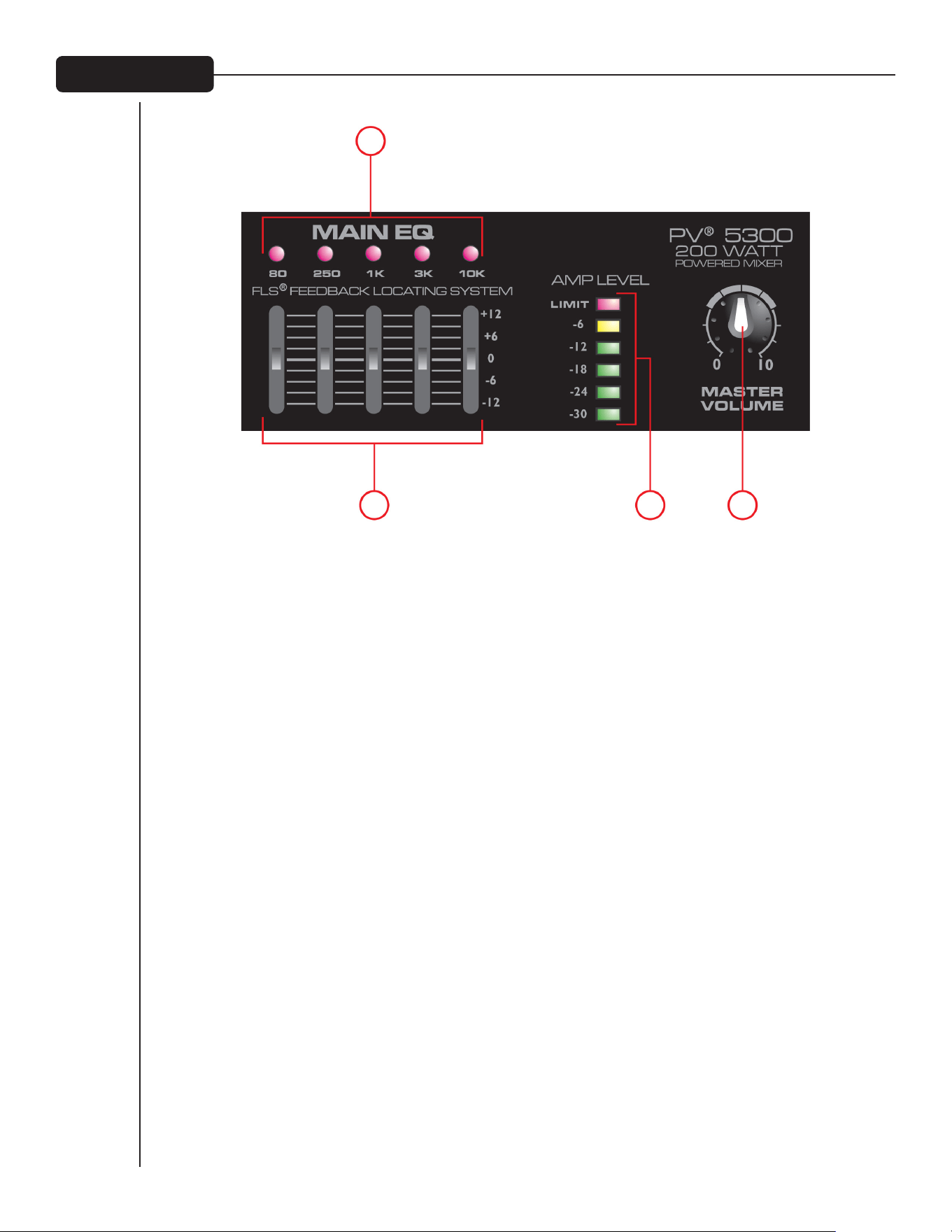
4
8
7
9 10
(7) FLS
®
FEEDBaCK LOCaTING SYSTEM
FLS Feedback Locating System 专利可简易快捷地从系统中去除回馈。当出现回馈时,与产生回馈频率波段相
对应的LED会在需调整的滑条上亮起,缓慢地将滑条向下拨动直到回馈消失,回馈消失后LED灯会继续亮几
秒钟。演出时LED灯偶尔会亮起是正常的,不一定就是出现了回馈。
(8) 图形EQ
5波段EQs是为12分贝切波或增强而设计的,用于对整个混音的微调,应少用。
(9) aMP LEVEL 梯度LED灯
这些LED灯表示进入功放器的信号大小,顶上的LED表示我公司革命性的DDT™扬声器保护电路的LIMIT以及
激活,该电路内置于PV 5300中并自动激活将功放器最大化,无需担心失真。
(10) MaSTERVOLUME
主混音以及功率混音器整体音量的主音量控制。
主均衡/主音量

5
11
14 15 16
12 13
(11) FOOTSWITCH
该1/4英寸插孔接收1/4英寸脚踏切换(Peavey零件号 03051000),
用于所有声道上回响音效的降噪。
(12) REC OUT
该RCA输出给CD录音机、立体声磁带机或其他录音设备的录音
输入提供信号。
注:不要将单个设备同时连接到录音输出和媒体输入
(8a/8B)。这样设置会产生一个回路,该回路将导致严
重回馈,有损坏用户设备的潜在危险。
(13) MaIN 输出
该1/4英寸插孔为外置功放器提供主混音(经图形EQ后)的信号。
(14) MUTE LED灯
当该灯亮起时表示声道1-4静音,不会向功放器传递信号。
(15) MUTE 开关
按下该按钮使 声道1-4静音,防止信号传递至功放器。该按钮
不会影响声道5。在演出间歇时该功能非常方便,它可以让音
乐在音响系统中播放,同时使线路/麦克风声道静音。
(16) 主 REVERB
对应声道上回响音效的整体大小。
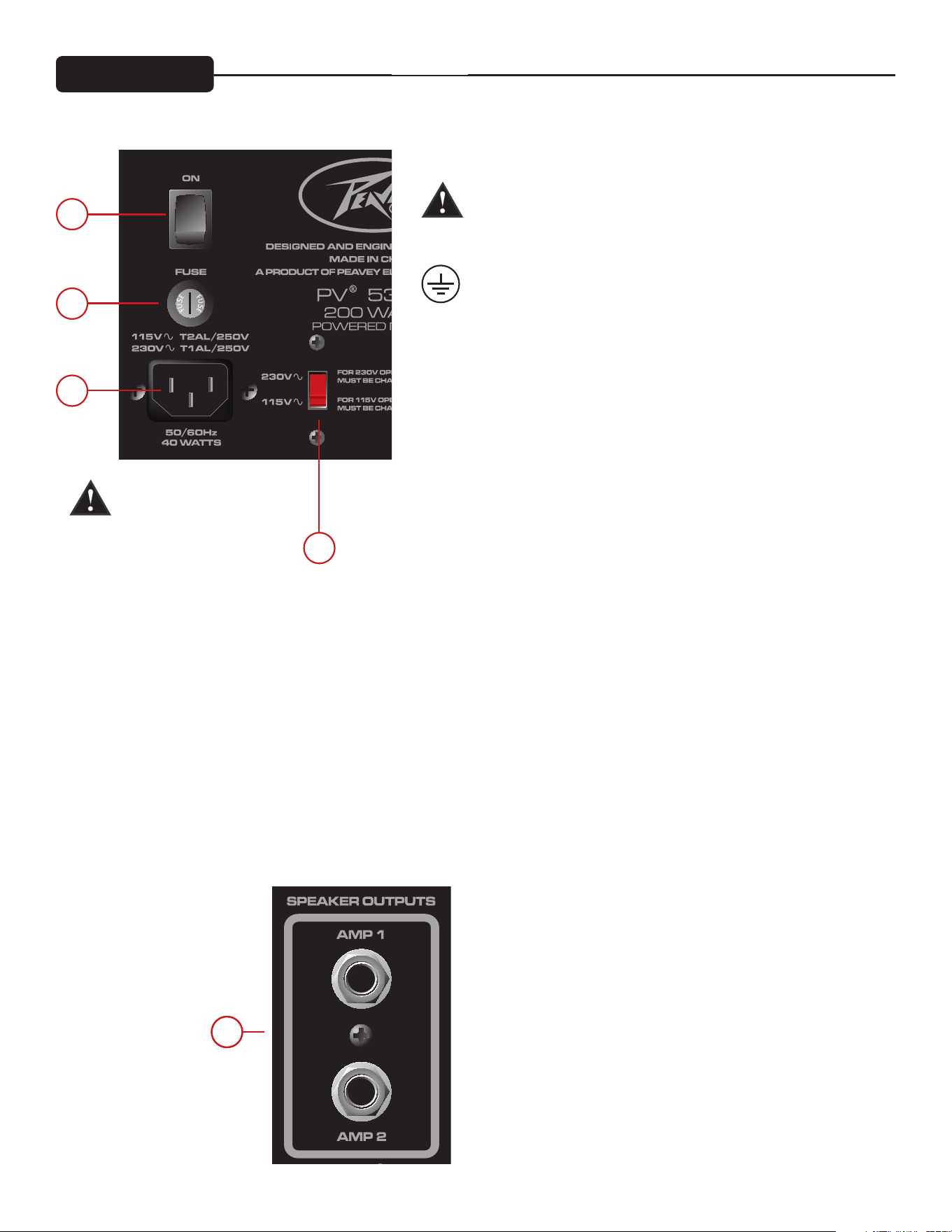
6
17
18
19
21
20
后面板
(17) 电源开关
这是主电源开关。
(18) 交流电源输入:
这是IEC线缆的接收插座,为设备提供交流电源,将线缆连接
到该插头为设备提供电源。如果使用了不正确的电压会损坏设
备(参见设备上的电压标示)。
为了用户安全,绝不能折断任何设备上的接地管脚。如果使用
的输出插座没有接地管脚,应采用适当的接地适配器且第三线
应正确接地。
为了防止电击或火灾的危险,请确保放大器和所有相关设备都
正确接地。
NOTE: FOR U.K. ONLY
As the colors of the wires in the mains lead of this apparatus
may not correspond with the colored markings identifying the
terminals in your plug, proceed as follows:
(1) The wire which is colored green and yellow must be connected
to the terminal which is marked by the letter E, or by the Earth
symbol, or colored green or green and yellow. (2) The wire
which is colored blue must be connected to the terminal which
is marked with the letter N, or the color black. (3) The wire which
is colored brown must be connected to the terminal which is
marked with the letter L, or the color red.
(19) FUSE
这是用于交流电压的主要安全保险丝,只能用相同类型和额定
值的保险丝更换。如果保险丝持续断开,请不要熔合保险丝,
而应将设备带到授权的Peavery维修中心。
注:如果改变了主交流电压,则必须更换保险丝,其额定值与
所用电压相匹配。
(20) 电压选择器开关
该开关允许用户在115VAC / 60Hz 或 230VAC / 50Hz之间选择。
如需改变电压,用户必须首先旋开并移去保护开关的塑料盖,
改变电压后请将塑料盖还原以确保电压值不会被随意改变。
注:保险丝也必须改变为适当的额定值以匹配用户所选电压。
正确值参见混音器后面的注释。
(21) SPEaKER OUTPUTS
这是双导体1/4英寸扬声器输出,每个具有额定的4欧姆最小阻
抗。用户可以连接一个4欧姆或一个8欧姆或两个8欧姆扬声器
到每个输出。不要在低于额定最小阻抗的情况下操作。为了实
现最大功率传输,连接扬声器时 请确保使用扬声器电缆而不是
仪器电缆。我公司推荐使用口径为18及以上的扬声器电缆。
注意: 改变电压或熔断值
前,确保组件从交流电源
断开。

性能与技术规格如有变更,恕不通知。
Peavey Electronics Corporation • 5022 Hartley Peavey Drive • Meridian, MS • 39305
(601) 483-5365 • FAX (601) 486-1278 • www.peavey.com • EX 000130 • ©2011
输入灵敏度:
麦克风输入至功率放大器的全功率主音量正常值
全功率 正常值
-48 dBu -28 dBu
线路输入至功率放大器的全功率主音量正常值
全功率 正常值
-18 dBu +3 dBu
声道均衡:
斜坡式均衡
低均衡 80 Hz ±15 dB
高均衡 12 kHz ±15 dB
削波灯
在削波频率的3分贝之前,削波灯亮起。
频率响应:
所有控制的正常值(止动)
麦克风到主输入 30 Hz – 20 kHz +0, -1 dB
线路到主输入 20 Hz – 30 kHz +0, -1 dB
麦克风到攻放 50 Hz – 20 kHz +0, -3 dB
线路到功放 40 Hz – 20 kHz +0, -3 dB
噪声:
主 = 主线路输出,22-22kHz过滤器
功放1 = 放大器输出,通过AP负荷为4欧姆
AUX-0025切换放大器过滤器
所有控制的最大值
主输入 <-95 dBu
放
大器1 <-70 dBu
主音量控制正常值
主输入 <-90 dBu
放大器1 <-67 dBu
总谐波失真:
所有控制正常值
<0.01% @主线源输出, -30 dBu麦克风输入
<0.09% @放大器1 输出调整为45瓦
所有控制正常值
<0.005% @主线路输出, +4 dBu线路输入
<0.08% @放大器1输出调整为45瓦
主均衡:
80 Hz +/-12 dB
250 Hz +/-12 dB
1 kHz +/-12 dB
3 kHz +/-12 dB
10 kHz +/-12 dB
计量组:
LIMIT 极值
-6 dB
-12 dB
-18 dB
-24 dB
-30 dB
放大器限幅器:
在削波前限制放大器功率,该限幅器无需削波并保持放大器功率,
并且能驱动至18分贝,超出最大输出。
放大器输出功率:
120VAC
两个声道负荷为8欧姆: 每声道30瓦RMS
每声道60瓦峰值
两个声道负荷为4欧姆: 每声道50瓦RMS
每声道100瓦峰值
功率要求:
国内: 120VAC 50/60HZ 40 Watts 正常值
出口: 230VAC 50/60HZ 40 Watts 正常值
大小:
尺寸: 高 x 宽 x 深
9" x 14" x 9"
重量: 14磅
技术参数
ឞܫቿՋFCC߿˖ኃ15ᦉѫᄉ᜵යὋୱͺѶᥕʽˏ˓్Ὑ1ឞܫʿၶథࠎ
࣯2ឞܫᮋଋԩԩҁᄉʹ࣯ὋӉહ࠭ᒰܰୱͺᄉ࣯nj


PEAVEY ELECTRONICS CORPORATION LIMITED WARRANTY
Effective Date: 09/15/2010
What This Warranty Covers
Your Peavey Warranty covers defects in material and workmanship in Peavey products purchased and serviced in the U.S.A. and Canada.
What This Warranty Does Not Cover
The Warranty does not cover: (1) damage caused by accident, misuse, abuse, improper installation or operation, rental, product modification or neglect; (2) damage occurring
during shipment; (3) damage caused by repair or service performed by persons not authorized by Peavey; (4) products on which the serial number has been altered, defaced or
removed; (5) products not purchased from an Authorized Peavey Dealer.
Who This Warranty Protects
This Warranty protects only the original purchaser of the product.
How Long This Warranty Lasts
The Warranty begins on the date of purchase by the original retail purchaser. The duration of the Warranty is as follows:
Product Category Duration
Guitars/Basses, Amplifiers, Preamplifiers, Mixers, Electronic Crossovers and Equalizers 2 years *(+ 3 years)
Drums 2 years *(+ 1 year)
Enclosures 3 years *(+ 2 years)
Digital Effect Devices and Keyboards and MIDI Controllers 1 years *(+ 1 year)
Microphones 2 years
Speaker Components 1 year
(incl. Speakers, Baskets, Drivers, Diaphragm Replacement Kits and Passive Crossovers)
Tubes and Meters 90 Days
Cables Limited Lifetime
AmpKit Link, Xport, Rockmaster Series, Strum’n Fun, RetroFire, GT & BT Series Amps 1 year
[* Denotes additional Warranty period applicable if optional Warranty Registration Card is completed and returned to Peavey by original retail purchaser within 90 days of purchase.]
What Peavey Will Do
We will repair or replace (at Peavey’s discretion) products covered by Warranty at no charge for labor or materials. If the product or component must be shipped to Peavey for
Warranty service, the consumer must pay initial shipping charges. If the repairs are covered by Warranty, Peavey will pay the return shipping charges.
How To Get Warranty Service
(1) Take the defective item and your sales receipt or other proof of date of purchase to your Authorized Peavey Dealer or Authorized Peavey Service Center.
OR
(2) Ship the defective item, prepaid, to Peavey Electronics Corporation, International Service Center, 412 Highway 11 & 80 East, Meridian, MS 39301. Include a detailed description
of the problem, together with a copy of your sales receipt or other proof of date of purchase as evidence of Warranty coverage. Also provide a complete return address.
Limitation of Implied Warranties
ANY IMPLIED WARRANTIES, INCLUDING WARRANTIES OF MERCHANTABILITY AND FITNESS FOR A PARTICULAR PURPOSE, ARE LIMITED IN DURATION TO THE LENGTH OF
THIS WARRANTY.
Some states do not allow limitations on how long an implied Warranty lasts, so the above limitation may not apply to you.
Exclusions of Damages
PEAVEY’S LIABILITY FOR ANY DEFECTIVE PRODUCT IS LIMITED TO THE REPAIR OR REPLACEMENT OF THE PRODUCT, AT PEAVEY’S OPTION. IF WE ELECT TO REPLACE THE
PRODUCT, THE REPLACEMENT MAY BE A RECONDITIONED UNIT. PEAVEY SHALL NOT BE LIABLE FOR DAMAGES BASED ON INCONVENIENCE, LOSS OF USE, LOST PROFITS,
LOST SAVINGS, DAMAGE TO ANY OTHER EQUIPMENT OR OTHER ITEMS AT THE SITE OF USE, OR ANY OTHER DAMAGES WHETHER INCIDENTAL, CONSEQUENTIAL OR
OTHERWISE, EVEN IF PEAVEY HAS BEEN ADVISED OF THE POSSIBILITY OF SUCH DAMAGES.
Some states do not allow the exclusion or limitation of incidental or consequential damages, so the above limitation may not apply to you.
This Warranty gives you specific legal rights, and you may also have other rights which vary from state to state.
If you have any questions about this Warranty or services received or if you need assistance in locating an Authorized Service Center, please contact the Peavey International
Service Center at (601) 483-5365.
Features and specifications are subject to change without notice.
Logo referenced in Directive 2002/96/EC Annex IV
(OJ(L)37/38,13.02.03 and defined in EN 50419: 2005
The bar is the symbol for marking of new waste and
is applied only to equipment manufactured after
13 August 2005

Logo referenced in Directive 2002/96/EC Annex IV
(OJ(L)37/38,13.02.03 and defined in EN 50419: 2005
The bar is the symbol for marking of new waste and
is applied only to equipment manufactured after
13 August 2005
U.S. customer warranty registration.

FROM:
Place
Postage
Here
Peavey Electronics Corporation
Attn: Warranty Department
P.O. Box 5108
Meridian, Ms 39302-5108