STAMINA PRODUCTS
MADE IN CHINA
©
2024 Stamina Products, Inc.
2024, 02
Product May Vary Slightly From Pictured.
This Product is Distributed Exclusively by
2040 N Alliance Ave, Springeld, MO 65803
Customer Care
1 (800) 375-7520
www.staminaproducts.com
CAUTION:
Weight on this product should not exceed 250 lbs.
When calling for parts or
service, please specify
the following numbers
:
Model#: 45-9850,
45-9851
S/N: _____________
Exercise can present
a health risk. Consult
a physician before
beginning any exercise
program with this
equipment. If you feel
faint or dizzy, immediately
discontinue use.
Serious bodily injury can
occur if this equipment is
not assembled and used
in accordance with the
owner’s manual.
Follow all safety
instructions in this
owner’s manual.
!
WARNING
Owner's
Manual
Download the müüv app
for a step-by-step assembly video

Quickstart Guide
Go to the App Store on your device or
scan the QR Code for quick access.
Download the müüv app to experience personalized
fitness coaching for your Tony Little Treadmill!
müüv also supports other exercise equipment you own and hundreds
of healthy activities like outdoor walking to make moving fun!
DOWNLOAD APP
Unlimited workouts for the Tony Little Treadmill
Assembly video included in the app
No subscription required
IMPORTANT
Apple, the Apple logo, iPhone, and iPod touch are trademarks of Apple Inc., registered in the U.S. and other countries. App Store is a service
mark of Apple Inc., registered in the U.S. and other countries. Google Play and the Google Play logo are trademarks of Google LLC.

TABLE OF CONTENTS
Safety Instructions ..................................... 3
FCC Statements .......................................... 4
Grounding Instructions .............................. 5
Before You Begin ........................................ 7
Equipment Warning, Caution & Notice Labels
... 8
Operational Instructions ............................. 9
Storage ....................................................... 16
Maintenance ............................................... 16
Conditioning Guidelines ........................... 18
Warm-Up and Cool-Down ......................... 19
Product Parts Drawing .............................. 20
Parts List .................................................... 21
Warranty ..................................................... 23
Fax/Mail Ordering Form ............................ 25
SAFETY INSTRUCTIONS
3
!
WARNING
Cancer and Reproductive Harm www.P65Warnings.ca.gov
Consult your physician before starting this or any exercise program. This is
especially important if you are over the age of 35, have never exercised before,
are pregnant, or suer from any health problem. This product is for home use
only. Do not use in institutional or commercial applications. Failure to follow all
warnings and instructions could result in serious injury or death.
To reduce the risk of serious injury, read the following Safety Instructions before
using the
inStride Treadmill
.
!
WARNING
!
WARNING
To reduce the risk of electrical shock, always unplug the power cord before performing the
maintenance, adjustments and cleaning procedures described in this manual.
The inStride Treadmill should never be left unattended when plugged in. Unplug from outlet when
not in use.
The inStride Treadmill is not intended for use by persons with reduced physical, sensory or mental
capabilities, or lack of experience of knowledge, unless they have been given supervision or
instruction concerning use by a person responsible for their safety.
Use the inStride Treadmill only for its intended use as described in this manual. Do not use
attachments not recommended by the manufacturer.
Todisconnect,turnallcontrolstotheoposition,thenunplugfromtheoutlet.
Connect the inStride Treadmill to a properly grounded outlet only, See Grounding Instructions.
The inStride Treadmill should only be used after a thorough review of the Owner’s Manual by all
exercisers and saved for future reference.
Make sure that the product is properly assembled and tightened before use.
We recommend that two people be available for assembly of this product.
Keep children under age 13 and pets away from the inStride Treadmill at all times. This product is
for adult use only.
It is recommended that you place this product on an equipment mat.
Set up and operate the inStride Treadmill on a solid level surface. Do not position the product on
loose or uneven surfaces.
Do not place the inStride Treadmill on thick carpet as it may interfere with proper ventilation. Also,
do not place the inStride Treadmill near water or outdoors.
Position the inStride Treadmill so that the wall plug is visible, accessible and away from heated
surfaces.
Make sure that adequate space of 4 feet wide x 6 feet long is available for access to and around
the product.
KeepngersclearofallpinchpointswhenfoldingandunfoldingtheinStrideTreadmill.
Before using, always inspect the product for worn parts that should be replaced or loose parts that
should be tightened.
Never move the Walking Belt (10) while the power is turned off. Do not operate the inStride
Treadmill if the power cord or plug is damaged, or if the treadmill is not working properly.

FCC Statements:
This equipment has been tested and found to comply with the limits for a Class B digital device, pursuant
to Part 15 of the FCC Rules. These limits are designed to provide reasonable protection against harmful
interference in a residential installation.
This equipment generates, uses and can radiate radio frequency energy. However, there is no
guarantee that interference will not occur in a particular installation. If this equipment does cause harmful
interferencetoradioorreception,whichcanbedeterminedbyturningtheequipmentoandon,theuser
is encouraged to try to correct the interference by one or more of the following measures:
Reorient or relocate the receiving antenna.
Increase the separation between the equipment and receiver.
Connect the equipment into an outlet on a circuit different from that to which the receiver is
connected.
Consult the dealer or an experienced technician for help.
This device complies with part 15 of the FCC Rules. Operation is subject to the following two conditions:
1) This device may not cause harmful interference, and
2) This device must accept any interference received, including interference that my cause undesired
operation.
MODIFICATION: Any changes or modifications not expressly approved by the grantee of this device
could void the user's authority to operate the device.
SAFETY INSTRUCTIONS
Always make sure the Uprights (2, 3) are locked properly by the Fixing Lever (19).
Always attach the Safety Key (50) to your clothing while using the inStride Treadmill.
DonotstepotheinStrideTreadmillwhileitisinmotion.
Keephandsandngersawayfrommovingpartsandavoidtouchingthebeltduringoperation.
Maintain proper posture and do not lean excessively on the handrails.
Start with a slow pace and gradually increase speed and intensity.
Avoid sudden speed or incline changes, as they may lead to loss of balance and accidents.
Stay hydrated during your workout.
DonotusetheinStrideTreadmillifyouareundertheinuenceofalcoholormedicationthatmay
aectyourbalanceorcoordination.
Alwayschoosetheworkoutwhichbesttsyourphysicalstrengthandexibilitylevel.Knowyour
limits and train within them.
Do not wear loose clothing while using the inStride Treadmill.
Always wear proper footwear such as running, walking, or cross training shoes.
Be careful to maintain your balance while assembling, mounting, using and dismounting the
inStride Treadmill. Loss of balance may result in a fall or serious bodily injury.
The inStride Treadmill should not be used by persons weighing over 250 pounds.
The inStride Treadmill should be used by only one person at a time.
The inStride Treadmill is for consumer use only. It is not for use in public or semipublic facilities.
To reduce the possibility of the treadmill overheating, do not operate the inStride Treadmill
continuously for longer than one hour.
4
The müüv Treadmill must be grounded. If a treadmill should malfunction or breakdown, grounding
provides a path of least resistance for electrical current to reduce the risk of electrical shock. The müüv
Treadmill is equipped with a cord having an equipment grounding conductor and a grounding plug. The
plug must be plugged into an appropriate outlet that is properly installed and grounded in accordance
with local codes and ordinances.
GROUNDING INSTRUCTIONS
5
Grounding Methods
Grounded
Outlet
Grounding
Pin
Grounded
Outlet Box
!
WARNING Improper connection of the equipment
grounding conductor can result in a risk of electric shock.
Checkwithaqualiedelectricianorservicemanifyouare
in doubt as to whether the product is properly grounded.
Do not modify the plug provided with the product. If it
will not fit the outlet, have a proper outlet installed by a
qualiedelectrician.
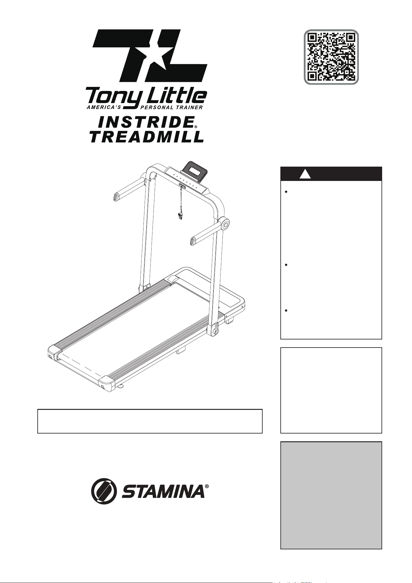
The müüv Treadmill is for use on a nominal 110-volt
circuit and has a grounding plug that looks like the plug
as showed in the illustration below. Make sure the müüv
Treadmill is connected to an outlet having the same
congurationastheplug.Noadaptershouldbeusedwith
this product. (This picture is just for reference.)
Treadmill Safety Key Use
:
1. Identify the safety key notch at the front center of the control panel.
2. Ensure that the SAFETY KEY(50) is not damaged or worn. If you
notice any issues, such as a frayed cord or a malfunctioning clip,
replace the SAFETY KEY(50) before use.
3. Insert the SAFETY KEY(50) into the notch on the control panel.
Push it in until it’s fully engaged.
4. Attach the clothespin clip to your clothes in front of your chest or
the nearest location. This ensures that the key is readily accessible
during your workout.
NOTE: Not required for “Walking Mode”. Ensure the lanyard and
clip do not come in contact with the WALKING BELT(10).
Using the SAFETY KEY(50) is a straightforward process designed to enhance user safety. Here’s a step-
by-step guide on how to use the SAFETY KEY(50). The SAFETY KEY(50) must be inserted for “Walking
Mode” as well as “Treadmill Mode” for the treadmill to work properly.
5. Turn on the power switch, the LED display will be fully displayed with a prompt sound.
WALKING MODE: Use the REMOTE CONTROL(49) to operate the functions of the treadmill.
TREADMILL MODE: You can use the REMOTE CONTROL(49) or use the function buttons on the
control panel to operate the treadmill.
NOTE: See manual for full control panel and remote control instructions.
6. Before starting your workout, double-check that the SAFETY KEY(50) is securely in place and properly
connected to the control panel.
7. Once the SAFETY KEY(50) is in position and the treadmill is powered on, you can start your workout
as usual.
NOTE: Always mount and dismount the treadmill while the WALKING BELT(10) is not moving.
8. In case of emergency or if you need to stop the treadmill quickly, simply detach the SAFETY KEY(50)
from the control panel by pulling it out of the notch. This action will trigger an immediate stop, bringing
the treadmill to a halt.
NOTE: Always stop the treadmill when switching between “Walking Mode” and “Treadmill Mode”.
Control
Panel
Notch

NEED HELP?
CONTACT US FIRST
1 (800) 375-7520
customer.care@staminaproducts.com
Hi! From all of us here at Stamina Products, thank you for your purchase. We
know that you have big fitness goals in mind and we are here to help you along.
Call us, email us, or send us a message on Facebook. Be sure to contact us if you
have any questions on your new product. We look forward to hearing from you!
With your body in mind,
Stamina Customer Care
To enact your extended warranty and to help us better
serve you, please go online and register your new product.
register.staminaproducts.com
ONLINE
customer.care@staminaproducts.com
www.staminaproducts.com
TELEPHONE
1 (800) 375-7520
FAX
(417) 889-8064
MAIL
Stamina Products, Inc.
ATTN: Customer Care
2040 N Alliance Ave
Springfield, MO 65803
facebook.com/StaminaProducts
facebook.com/AeroPilates
CUSTOMER CARE HOURS:
Monday-Thursday, 7:30 AM-5:00 PM, Central Time
Friday, 8:00 AM-3:00 PM, Central Time
It is quick and easy to register online, but if you’re a little old school or just need a
reason to raise that little flag on your mailbox, fill out the info on the last page of this
manual and mail it in.
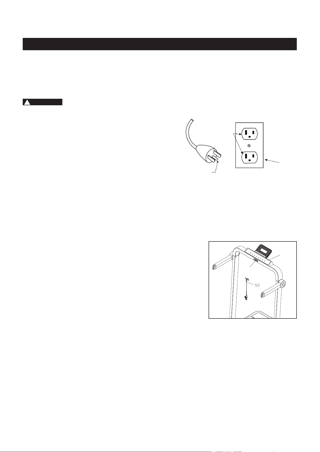
Left Upright
Left Rear Cap
Walking Belt
Warning Label 2
Display Overlay
Fixing Lever
Handrail
Rear Cover
Right Upright
Handrail
Control Panel Cover
BEFORE YOU BEGIN
7
Warning Label 1
Left Side Molding
Safety Key
Right Side Molding
Tablet Holder
Thank you for choosing the inStride Treadmill.
We take great pride in this quality product and
hope it will provide many hours of quality exercise
to make you feel better, look better, and enjoy life
to its fullest.
It's a proven fact that a regular exercise program
can improve your physical and mental health.
Too often, our busy lifestyles limit our time and
opportunity to exercise. The inStride Treadmill
provides a convenient and simple method to begin
your journey of getting your body in shape and
achieving a happier and healthier lifestyle.
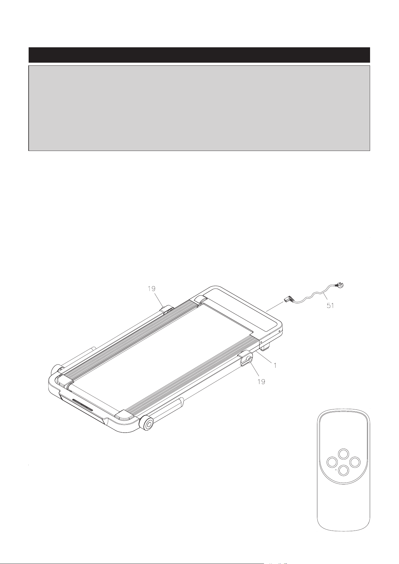
Before reading further, please review the
drawing below and familiarize yourself with the
parts that are labeled. Locate the serial decal on
the product and write the serial number on the
cover of the manual in the space provided. See the
next page for an image of the serial decal. Model
number and serial number are required when
calling for assistance.
Read this manual carefully before using the
inStride Treadmill.
Providing you with a quality product is Stamina's
top priority. However, sometimes there could be a
missing or incorrectly sized part. If you have any
questions or problems with the parts included with
your inStride Treadmill, please do not return the
product. Contact us FIRST!
If a part is missing or defective, please contact
Customer Care for assistance. Call us toll free
at 1-800-375-7520 (in the U.S.) or live chat on
staminaproducts.com.OurCustomerCareStais
available to assist you from 7:30 A.M. to 5:00 P.M.
(Central Time) Monday through Thursday and 8:00
A.M. to 3:00 P.M. (Central Time) on Friday.
Be sure to have the name and model number of
the product available when you contact us.
Serial Decal
Warning Label 2
Motor Cover
THE FOLLOWING TOOLS ARE INCLUDED FOR ASSEMBLY :
Allen Wrench (6mm)
Fixing Lever
Warning Label
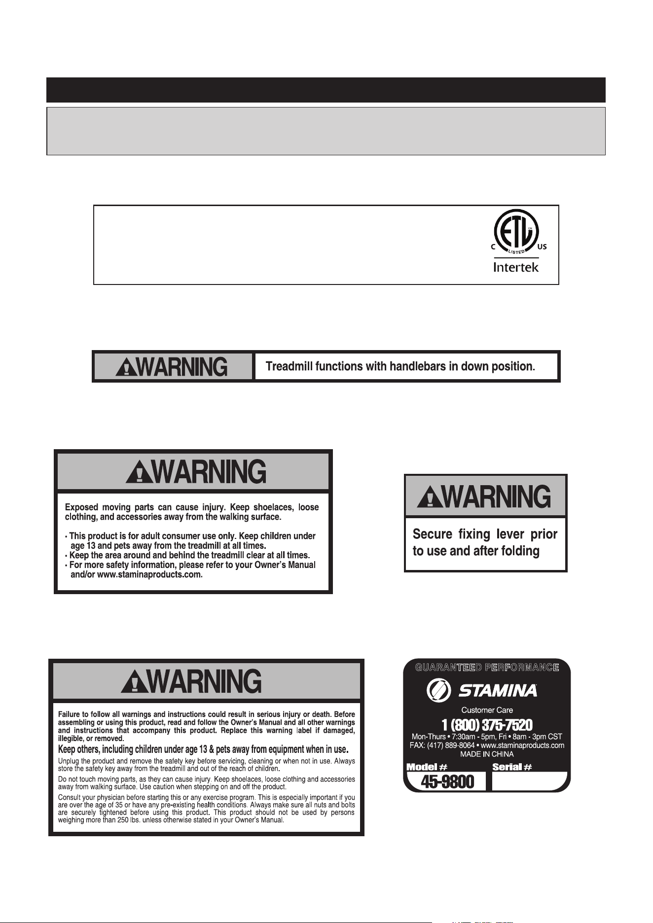
This chart is provided to help identify the warning, caution, and notice labels on the inStride Treadmill.
Please take a moment to familiarize yourself with all of the warning, caution, and notice labels.
EQUIPMENT WARNING, CAUTION & NOTICE LABELS
8
WARNING LABEL 1 (82)
To best serve you, our Customer Care
Representatives will need your serial
number. For quick access, write in your
serial number on the cover of the manual.
SERIAL DECAL(86)
WARNING LABEL 2 (83)
FIXING LEVER WARNING LABEL (84)
Stamina Products, Inc.
2040 N. Alliance Ave
Springeld, MO 65803
1-800-375-7520
MADE IN CHINA
Model: 45-9850/45-9851
Motor: 1.0 HP DC, Class A
Power: 735 W
Ratings: 120V, 6A, 60Hz
FOR CONSUMER USE ONLY
Max. User Weight: 250lbs
Contains FCC ID: AUIE-FSBTC
Conforms to UL STD 1647
Certied to CSA STD C22.2 #68
This device complies with Part 15 of the FCC Rules. Operation
is subject to the following two conditions: (1) this device may not
cause harmful interference, and (2) this device must accept any
interference received, including interference that may cause
undesired operation of the device.
5027636
INTERTEK ETL LABEL(85)
WARNING LABEL 3 (88)
OPERATIONAL INSTRUCTIONS
9
WALKING MODE
The inStride Treadmill is a fully assembled product. Remove the inStride Treadmill from its carton, and
remove all packing materials from the product. Place the inStride Treadmill as shown in the illustration
below. Check and make sure the FIXING LEVERS(19) are securely tightened. Plug the POWER
CORD(51) into the socket on the front of the MAIN FRAME(1), and plug the POWER CORD(51) into an
electrical outlet. Then you can use the inStride Treadmill in its walking mode directly.
NOTE:
Placeallpartsfromtheboxinaclearedareaandpositionthemontheoorinfrontofyou.Remove
all packing materials from your area and place them back into the box. Do not dispose of the packing
materials until assembly is completed. Read each step carefully before beginning. If you are missing
a part, please go to staminaproducts.com under the Customer Care section and order the part
needed, e-mail us at customer[email protected], or call us toll free at 1-800-375-7520
(intheU.S.).OurCustomerCareStaisavailabletoassistyoufrom7:30A.M.to5:00P.M.(Central
Time) Monday through Thursday and 8:00 A.M. to 3:00 P.M. (Central Time) on Friday.
Some product parts are t tested at the factory to ensure proper t and alignment. Marks in
the paint may be noticeable, but are not an indication of damage.
1. You should use the REMOTE CONTROL(49) to operate the functions of the inStride Treadmill
in the walking mode.
2. The maximum speed of the walking mode is 2.5 miles per hour.
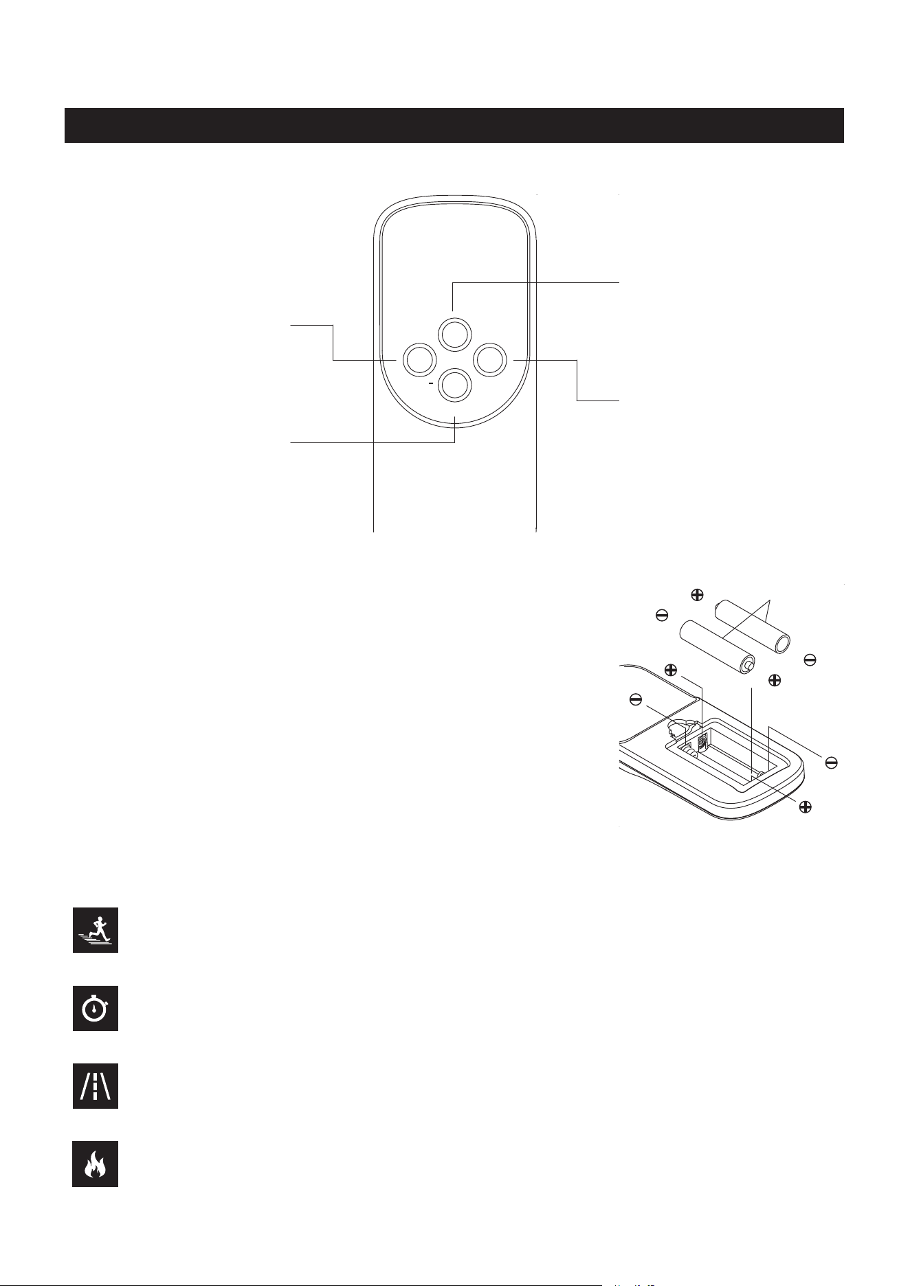
REMOTE CONTROL(49)
See page 13 for detailed remote
operational instructions.
PAUSE/STOP
START
SPEED SPEED+
OPERATIONAL INSTRUCTIONS
10
1.
3.
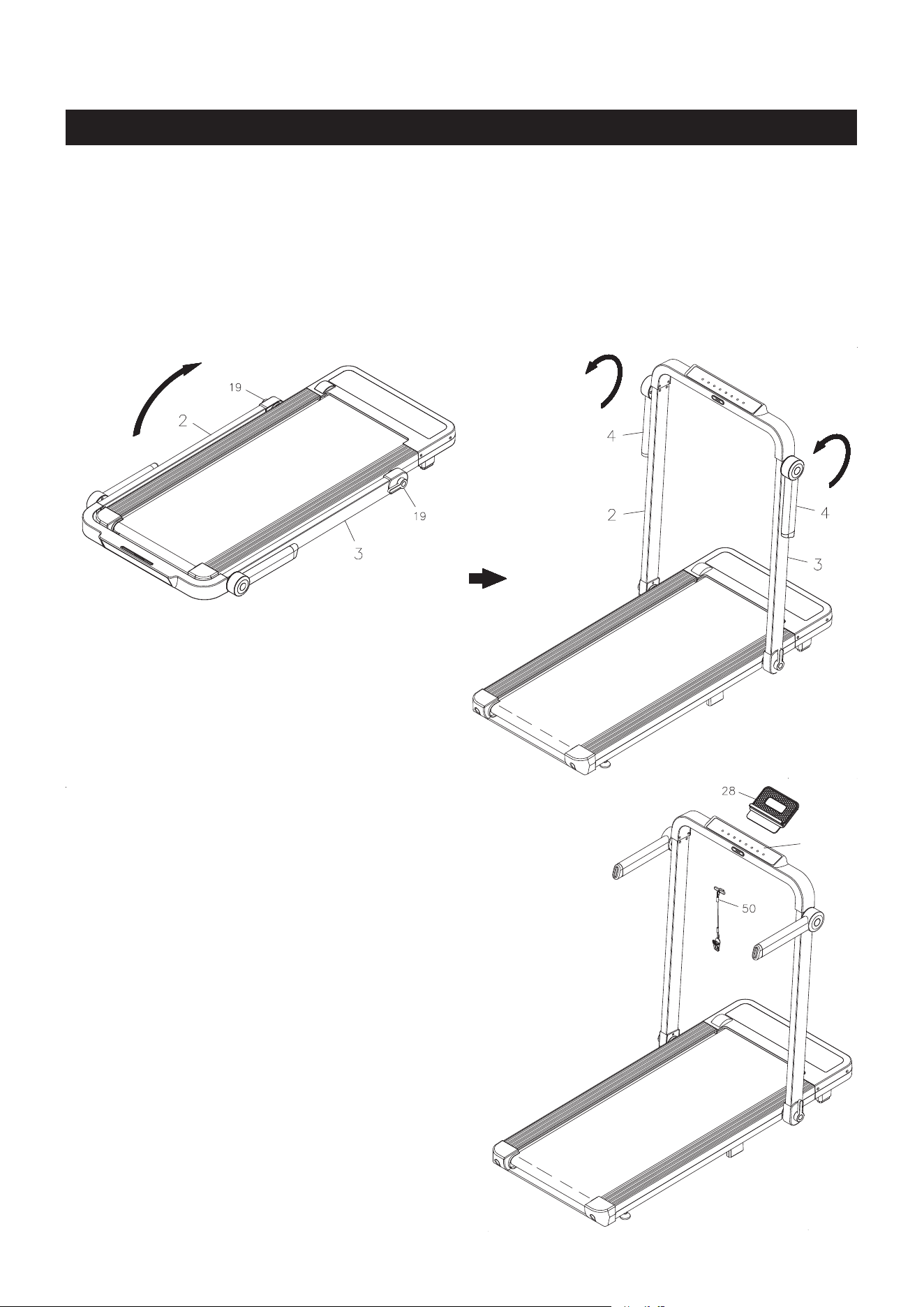
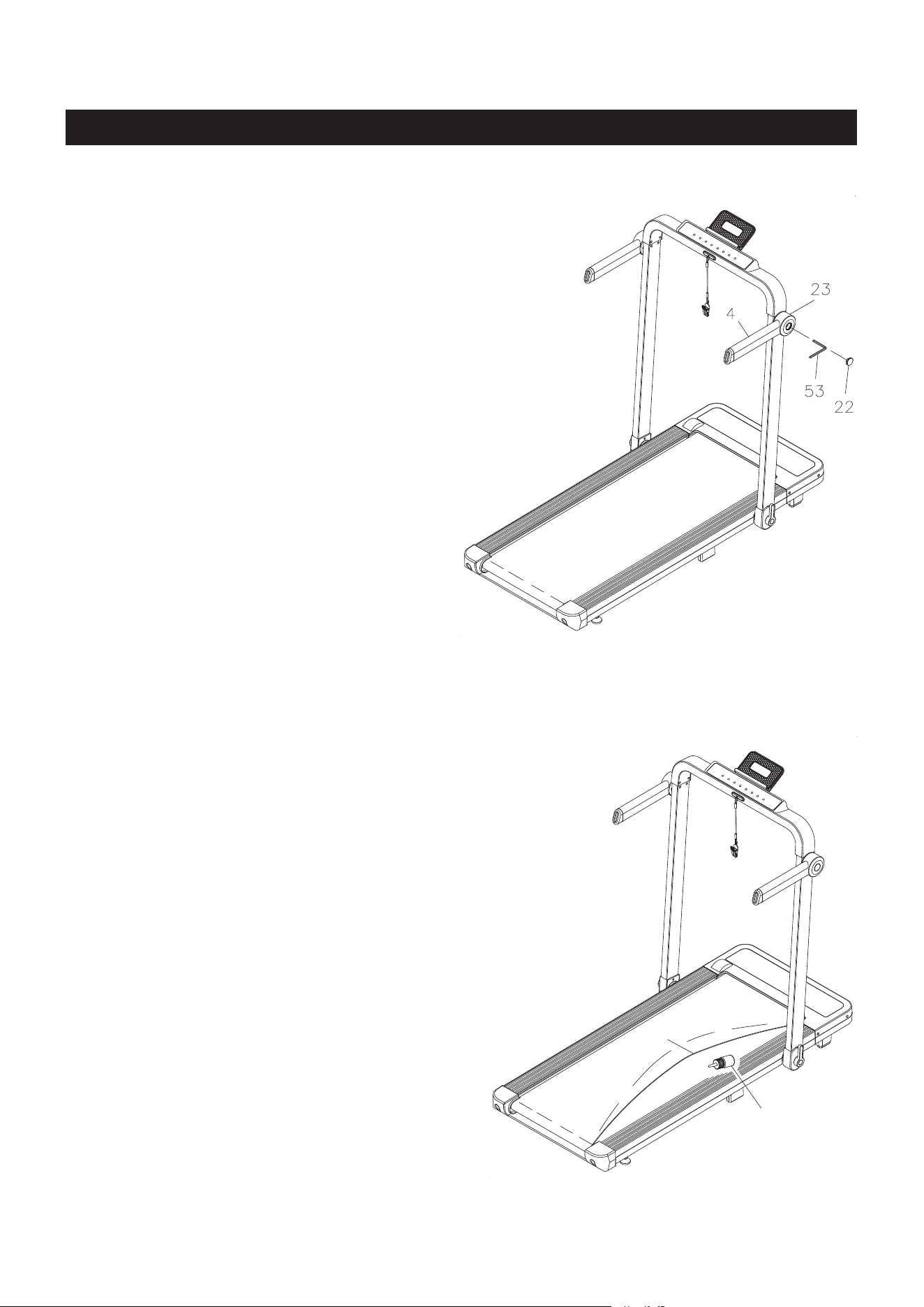
TREADMILL MODE
Follow the illustrated process below to unfold the inStride Treadmill to go into the treadmill mode:
1. Refer to illustration 1. Turn the FIXING LEVERS(19) counterclockwise 4 to 5 turns to loosen the
LEFT and RIGHT UPRIGHTS(2, 3). Lift up the UPRIGHTS(2, 3) to the "stop" and lock in position by
turning the FIXING LEVERS(19) clockwise. Always make sure the FIXING LEVERS(19) are securely
tightened.
2. Refer to illustration 2. Swing the HANDRAILS(4) around as shown in the illustration so they point to
the back of the treadmill.
2.
Control
Panel
3. Your
müüv Treadmill should look as shown in illustration 3.
Insert the SAFETY KEY(50) into the notch at the front of the
control panel.
NOTE: Attach the clothespin clip to your clothes in front of
your chest or the nearest location. This ensures that the
SAFETY KEY(50) is readily accessible during your workout.
4. The TABLET HOLDER(28) is optional and can be taken on
andoasneeded.TousetheTABLET HOLDER(28), insert
it into the slot located at the back of the control panel. Place
your tablet device on the TABLET HOLDER(28).
NOTE:
1. Stop the treadmill when switching the functions between the
walking mode and treadmill mode of the treadmill.
2. Keepngersclearofallpinchpointswhen
folding and unfolding the treadmill.
3. Revert the above procedure to fold the
treadmill for storage.
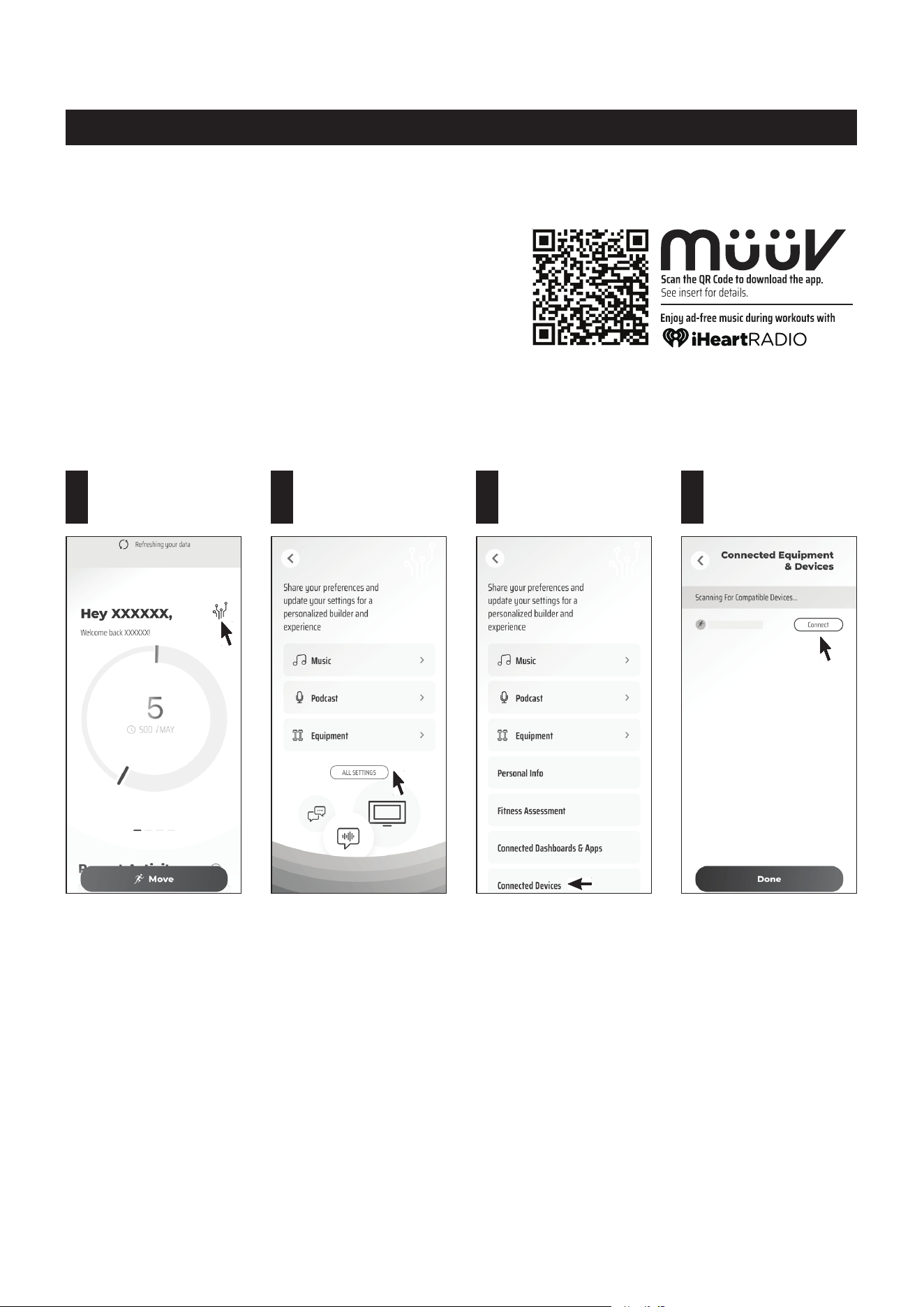
OPERATIONAL INSTRUCTIONS
Tap on the Setting
icon.
1
Tap on
ALL SETTINGS.
2
Tap on Connected
Devices.
3
Tap on Connect next
to the "TL9850/9851"
to connect.
4
NOTE:
1. To fully operate your inStride Treadmill you will need to
download the free müüv app.
2. You will need to enable bluetooth in your phone settings
rst.
Power on the inStride Treadmill. Open the müüv app and follow the process below to connect the treadmill
to the müüv app. It will make your inStride Treadmill work with the müüv application and many others. For
more detailsandinformation,govisithttps://müüv.t.
TL9850/9851
müüv
CONNECTION OPERATION
11

USING THE FITNESS METER
12
OPERATIONAL INSTRUCTIONS
GUIDELINES FOR USE:
Plug the POWER CORD(51) into the socket on the front of the BASE FRAME(1), and plug the
POWER CORD(51) into an electrical outlet with safety grounding. Turn on the power switch, the LED
display will be fully displayed with a prompt sound.
Place the SAFETY KEY(50) into the notch at the front of the control panel, and clip the clothespin to
the clothes in front of your chest.
The electronic control system is under safety monitoring at all times. If any abnormality is found, the
running treadmill will stop in an emergency, and the LED display will display the error code.
Control Panel
LED Display
FUNCTION BUTTONS:
START :
STOP:
(Minus):
(Plus):
There are four speed shortcut buttons of 1 mph, 3 mph, 5 mph, and 7 mph. When running the
treadmill, if you select one of the preset speed value, the speed will start slowly and increase
up to the selected speed.
SPEED SHORTCUT BUTTONS:
Press to start running the treadmill.
Press to pause the treadmill and all function values will be kept. You can press the START
button to continue the workout with these function values, or press the STOP button again
to reset all functions to zero.
Press to decrease the SPEED when running the treadmill.
Press to increase the SPEED when running the treadmill.
OPERATIONAL INSTRUCTIONS
DISPLAY INSTRUCTIONS
Displays the calories consumption from zero to 999 Kcal.
NOTE: The calorie readout is an estimate for an average user. It should be used only as a
comparison between workouts on this unit.
Displays the current speed from zero to 7.5 miles per hour.
Displays the time during exercise from one second up to 99:59 minutes.
Displays the distance from zero to 99.9 miles.
13
REMOTE CONTROL FUNCTIONS:
Press to pause the treadmill and all
function values will be kept. You can
press the START button to continue
the workout with these function
values, or press this button again
to reset all functions to zero.
P
ress to start running the treadmill.
Press to decrease the SPEED when
running the treadmill.
Press to increase the SPEED when
running the treadmill.
1. Do not mix a new battery with an old battery.
2. Use the same type of battery. Do not mix an alkaline battery
with another type of battery.
3. Rechargeable batteries are not recommended.
4. Ultimate disposal of battery should be handled according
to all state and federal laws and regulations.
5. Do not dispose of batteries in re.
NOTE:
1. Open the battery door on the back of the REMOTE CONTROL(49).
2. The REMOTE CONTROL(49) operates with two AAA batteries (1.5V
each), the batteries are not included. Refer to the illustration to install
or replace the batteries.
HOW TO INSTALL AND REPLACE BATTERIES:
AAA Batteries
PAUSE/STOP
START
SPEED SPEED+

OPERATION NOTES:
When you press the START button to start running the treadmill, the TIME display window will count
down the numbers “3 - 2 - 1” with a prompt sound, then start the treadmill from the speed 0.5 miles per
hour.
The maximum speed of the walking mode is 2.5 miles per hour. The maximum speed of the treadmill
mode is 7.5 miles per hour.
Whenthetreadmillisrunning,youcanturnothepowerswitchtoshutdownthetreadmillinanytime.
This will not damage the treadmill.
OPERATIONAL INSTRUCTIONS
14
Possible Cause Corrective Action
Error
Code
ERROR CODE AND TROUBLESHOOTING
Software over current Unplug the power cord and replug it, the main reason is overload.
Unplug the power cord and replug it, the main reason is overload.
Turn off the power switch for 30 minutes then use normally, the
main reason is overload.
The input voltage of the power supply is too low or the control
board is damaged. Check whether the voltage of the power supply
is normal. If the voltage is normal, replace the control board.
The power input voltage is too high or the control board is
damaged. Check whether the voltage of the power supply is
normal. If the voltage is normal, replace the control board.
Check whether the motor wiring is normal. If normal, replace the
control board or motor.
Unplug the power cord and replug it, then use normally, the main
reason is overload or motor/roller stuck.
Check whether the transmission parts are normal.
Motor/roller stuck, check whether the transmission parts are
normal. Change the motor or control board as necessary.
Running for a long time with high resistance, lubricate the
treadmill.
Change motor.
Running for a long time with high resistance, lubricate the
treadmill.
Change motor.
Change control board (within the max. rated load).
Check whether the upper and lower control communication cables
are correctly connected. Or, replace the cables as necessary.
Check whether the communication interface of the upper
controller is normal. Or change the upper controller as necessary.
Check whether the communication interface of the lower
controller is normal. Or change the lower controller as necessary.
Check whether the key board communication interface is normal.
Or replace the communication board as necessary.
Hardware over current
IPM module overheating
Under voltage protection
Over voltage protection
Motor out of phase
protection
Motor blocking protection
Motor won't start
Motor over current
protection
Overload protection
Communication problem
of up-down control
The key board
communication is abnormal
E01
E02
E03
E04
E05
E06
E07
E08
E09
E10
E12
E20
OPERATIONAL INSTRUCTIONS
TREADMILL ADJUSTMENTS
RIGHT
ADJUSTMENT
LEFT
ADJUSTMENT
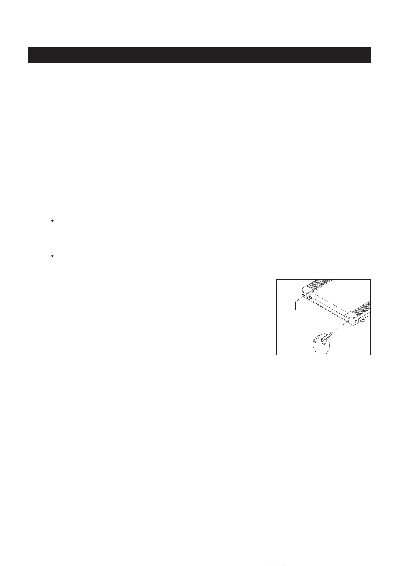
When adjusted properly, the inStride Treadmill’s WALKING BELT(10) will roll smoothly around the WALKING
BOARD(9) and over the front and rear rollers without catching or rubbing. For the belt to run smoothly,
there are a few points that need to be noted.
BELT ALIGNMENT
The WALKING BELT(10) must be in the center of the WALKING BOARD(9) to prevent it from rubbing
against the MOTOR COVER(11). If the belt rubs the MOTOR COVER(11),itwillbediculttokeepthe
belt moving and will eventually damage the edge of the belt. The treadmill has belt guides at the bottom of
the treadmill frame that move the belt toward the center of the treadmill. However, the REAR ROLLER(8)
must be properly aligned with the treadmill frame and FRONT ROLLER(7) if the belt is to remain centered
on the treadmill. The bolts in the rear of the treadmill (one on the left and the other on the right) adjust the
alignment of the REAR ROLLER(8) as well as the tension of the belt.
The belt will run to the side that has the loose rear bolt.
Hint:
BELT DRIFTING LEFT
Adjust by turning the left screw 1/4 turn CLOCKWISE and the right screw
1/4 turn COUNTERCLOCKWISE. Walk on the treadmill to check alignment.
Repeat if needed.
BELT DRIFTING RIGHT
Adjust by turning the left screw 1/4 turn COUNTERCLOCKWISE and the
right screw 1/4 turn CLOCKWISE. Walk on the treadmill to check alignment.
Repeat if needed.
NOTE:
When you believe the WALKING BELT(10) is centered, use the treadmill for three (3) minutes to verify the
WALKING BELT(10) won’t drift to one side or the other. If the WALKING BELT(10) continues to drift, the
oormaynotbelevel.Rotatethetreadmill90degreesormovethetreadmilltoanotherlocation.
BELT TENSION
The WALKING BELT(10) should be taut and not lying loosely on the treadmill WALKING BOARD(9). If
the belt is too loose, it will slip on the front roller and you will notice a jerky movement when you walk on
thetreadmill.Ifthebeltistootight,theedgesofthebeltwillbegintocurlandmoreeortwillberequiredto
move the belt. Excessive belt tension can also damage the bearings in the rollers. The bolts on the ends
of the MAIN FRAME(1) (one on the left and the other on the right) adjust the WALKING BELT(10) tension
as well as the REAR ROLLER(8) alignment.
BELT TOO LOOSE: Use the 6mm ALLEN WRENCH to tighten the bolts on the ends of the MAIN FRAME(1).
Tighten both bolts 1/4 turn clockwise at a time until the belt stops slipping on the FRONT ROLLER(7).
BELT TOO TIGHT : Use the 6mm ALLEN WRENCH to loosen the bolts on the ends of the MAIN FRAME(1).
Loosen both bolts 1/2 turn counterclockwise at a time until the belt begins to slip on the FRONT ROLLER(7).
Then use the procedure above to tighten the belt to the proper tension.
15
Visually check the REAR ROLLER(8) to make sure both the right side and the left side of
the REAR ROLLER(8) are the same distance from the back edge of the treadmill. Using
the 6mm ALLEN WRENCH, make adjustments by turning the bolts clockwise to tighten and
counterclockwise to loosen.
When doing the adjustment and checking whether the belt is in the center, you can power on the
treadmill and run it with speed 3 mph to check for 1 - 2 minutes.

STORAGE
The safety and integrity designed into the inStride Treadmill can only be maintained when the inStride
Treadmill is regularly examined for damage and wear. Special attention should be given to the following:
MAINTENANCE
To store the inStride Treadmill, simply keep it in a clean dry place.
To move the inStride Treadmill, hold the back end of the inStride Treadmill and tilt the inStride
Treadmill onto the wheels under the LOWER MOTOR COVER(12) at the front.
The minimum folded dimensions of the inStride Treadmill are approximately 53.6 inches long x 22.3
inches wide x 9.1 inches tall. Please measure your inStride Treadmill if exact dimensions are needed.
To avoid damage to the electronics, remove the batteries from the remote before storing the inStride
Treadmill for one year or more.
Periodic cleaning will greatly prolong the life of the treadmill. Keep treadmill clean by dusting regularly.
Be sure to clean the exposed part of the deck on either side of the walking belt and also the side rails.
Wearing clean running shoes will reduce the build up of foreign material underneath the walking belt.
Always make sure the UPRIGHTS(2, 3) are locked properly by the FIXING LEVER(19).
Verify that all nuts and bolts are present and properly tightened. Replace missing nuts and bolts.
Tighten loose nuts and bolts.
Verify that the CAUTION LABEL(50) is in place and easy to read. Call Stamina Products immediately
at 1-800-375-7520 for a replacement CAUTION LABEL(50) if it is missing or damaged.
It is the sole responsibility of the user/owner to ensure that regular maintenance is performed.
Worn or damaged parts must be replaced immediately or the inStride Treadmill removed from service
until repair is made.
Only Stamina Products supplied components should be used to maintain/repair the inStride Treadmill.
If the WALKING BELT(10) does not move easily, lubricate the WALKING BOARD(9) under the
WALKING BELT(10) with silicone lubricant.
16
!
WARNING Always unplug the treadmill from the electrical outlet before cleaning or servicing
the
inStride Treadmill
.
17
MAINTENANCE
HANDRAIL ADJUSTMENT
Over time the HANDRAIL(4) may loosen. You can remove the
ROUND PLUG(22) from the HANDRAIL COVER(23). Use the
ALLEN WRENCH(6mm)(53) to tighten the FLAT SOCKET
HEAD BOLT(M10x1.45x30)(74) which is located on the inside
of the cover. The HANDRAIL(4) must be able to rotate, do not
overtighten the bolt. Press the ROUND PLUG(22) back into
the HANDRAIL COVER(23).
WALKING BELT AND BOARD LUBRICATION
If the WALKING BELT(10) does not move easily, or every 600
hours of use, lubricate the WALKING BOARD(9) with 100%
silicone lubricant. Lift one side of the WALKING BELT(10),
apply approximately 20 ml of lubricant to the center of the
WALKING BOARD(9). Start the treadmill at the lowest
speed to allow the lubricant to spread all over the WALKING
BOARD(9).
Silicone Oil
Belt
How you begin your exercise program depends on your physical condition. If you have been inactive for
several years or are severely overweight, start slowly and increase your workout time gradually. Increase
your workout intensity gradually by monitoring your heart rate while you exercise.
Initially you may only be able to exercise within your target zone for a few minutes; however, your aerobic
capacity will improve over the next six to eight weeks. It is important to pace yourself while you exercise
so you don't tire too quickly.
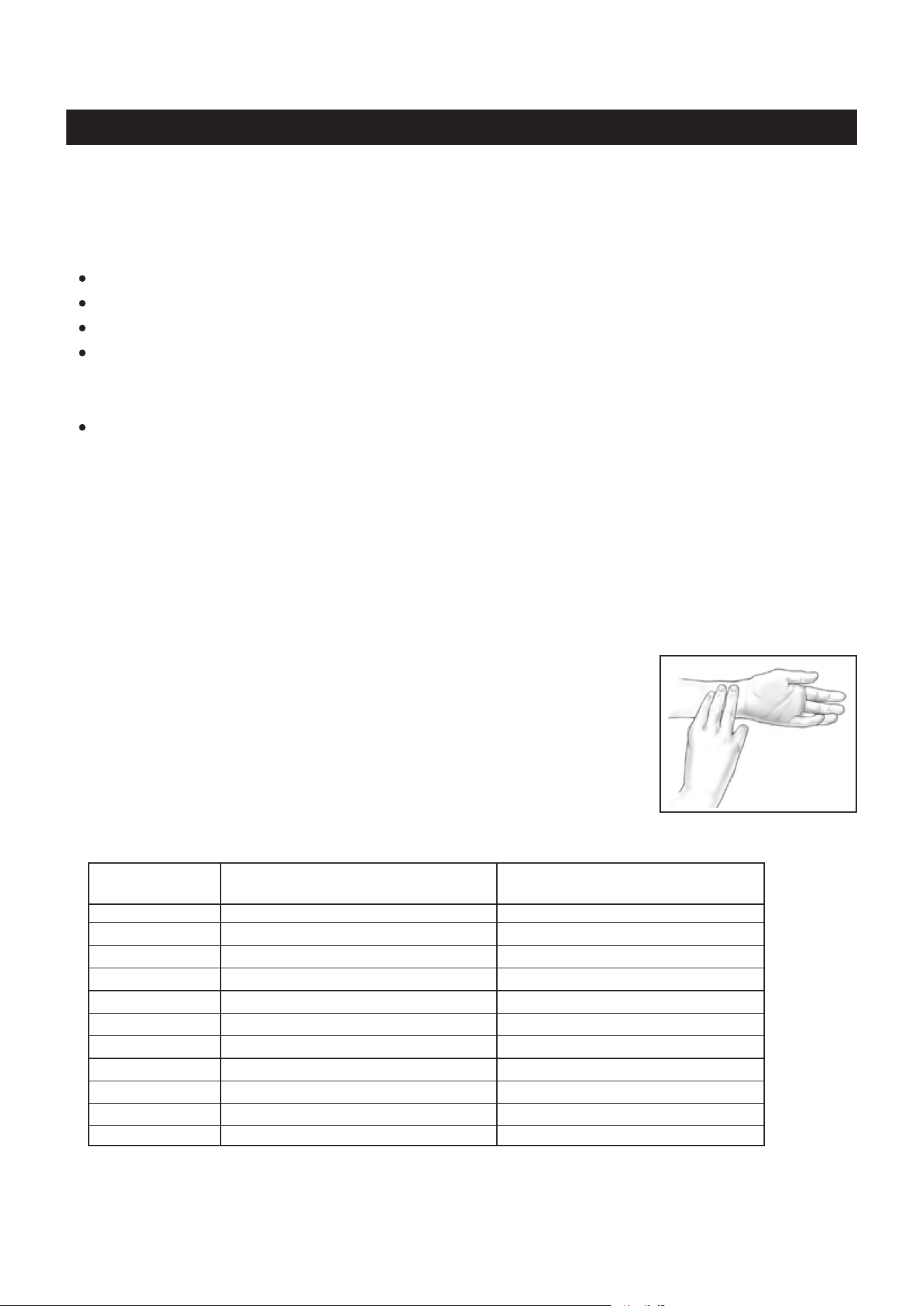
Measure your heart rate periodically during your workout by stopping the
exercise but continuing to move your legs or walk around. Place two or
threengersonyourwristandtakeasixsecondheartbeatcount.Multiply
theresultsbytentondyourheartrate.Forexample,ifyoursixsecond
heartbeat count is 14, your heart rate is 140 beats per minute. A six second
count is used because your heart rate will drop rapidly when you stop
exercising. Adjust the intensity of your exercise until your heart rate is at the
proper level.
wrist pulse
Remember to follow these essentials:
Have your doctor review your training and diet programs.
Begin your training program slowly with realistic goals that have been set by you and your physician.
Warm up before you exercise and cool down after you work out.
Take your pulse periodically during your workout and strive to stay within a range of 60% (lower
intensity) to 90% (higher intensity) of your maximum heart rate zone. Start at the lower intensity, and
builduptohigherintensityasyoubecomemoreaerobicallyt.
If you feel dizzy or lightheaded you should slow down or stop exercising.
To determine if you are working out at the correct intensity, use a heart rate monitor or use the table
below. For effective aerobic exercise, your heart rate should be maintained at a level between 60%
and 90% of your maximum heart rate. If just starting an exercise program, work out at the low end of
your target heart rate zone. As your aerobic capacity improves, gradually increase the intensity of your
workout by increasing your heart rate.
CONDITIONING GUIDELINES
Target Heart Rate Zone Estimated by Age*
* For cardiorespiratory training benefits, the American College of Sports Medicine recommends
working out within a heart rate range of 55% to 90% of maximum heart rate. To predict the
maximum heart rate, the following formula was used: 220 - Age = predicted maximum heart rate
20 years
25 years
30 years
35 years
40 years
45 years
50 years
55 years
60 years
65 years
70 years
Average Maximum
Heart Rate 100%
Age
110-180 beats per minute
107-175 beats per minute
105-171 beats per minute
102-166 beats per minute
99-162 beats per minute
97-157 beats per minute
94-153 beats per minute
91-148 beats per minute
88-144 beats per minute
85-139 beats per minute
83-135 beats per minute
200 beats per minute
195 beats per minute
190 beats per minute
185 beats per minute
180 beats per minute
175 beats per minute
170 beats per minute
165 beats per minute
160 beats per minute
155 beats per minute
150 beats per minute
Target Heart Rate Zone
(55%-90% of Maximum Heart Rate)
18

19
WARM-UP and COOL-DOWN
Warm-Up
The purpose of warming up is to prepare your body for exercise and to minimize injuries.
Warm up for two to ve minutes before strength training or aerobic exercising. Perform activities that
raise your heart rate and warm the working muscles. Activities may include brisk walking, jogging,
jumping jacks, jump rope, and running in place.
Cool-Down
The purpose of cooling down is to return the body to its normal, or near normal, resting
state at the end of each exercise session. A proper cool-down slowly lowers your heart rate and allows
blood to return to the heart. Your cool down should be completed after each strength training session.
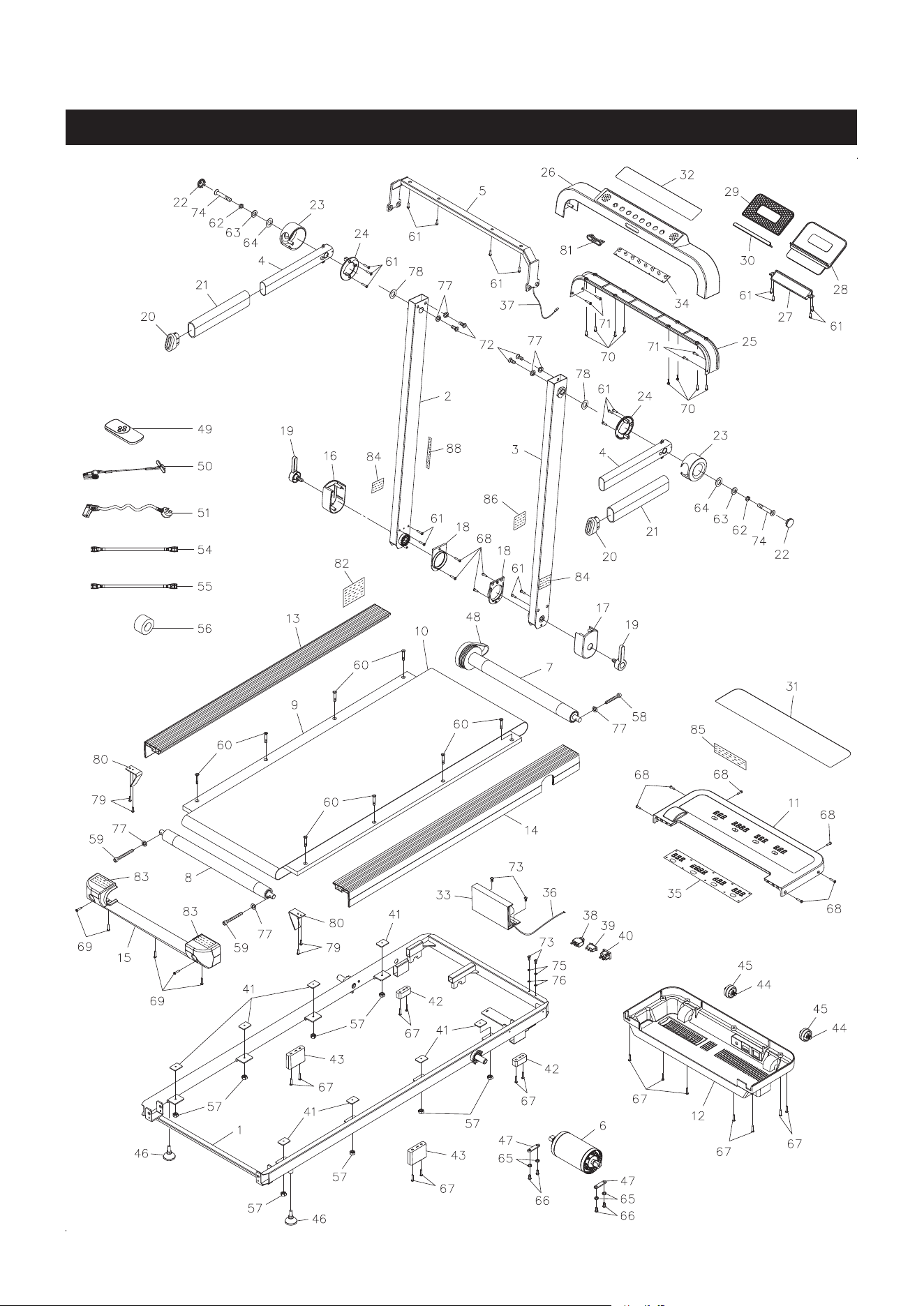
PRODUCT PARTS DRAWING
20
FRONT
BACK

PART# PART NAME QTY
PARTS LIST
21
1 Main Frame 1
2 Left Upright 1
3 Right Upright 1
4 Handrail 2
5 Crossing Frame 1
6 Motor (1.0HP, 5A, 746w, brushless motor) 1
7 Front Roller w/ Flywheel 1
8 Rear Roller 1
9 Walking Board 1
10 Walking Belt 1
11 Motor Cover 1
12 Lower Motor Cover 1
13 Left Side Molding 1
14 Right Side Molding 1
15 Rear Cover 1
16 Left Upright Lower Cover 1
17 Right Upright Lower Cover 1
18 Upright Inner Support Plate 2
19 Fixing Lever 2
20 Handrail Cap 2
21 Foam Grip 2
22 Round Plug 2
23 Handrail Cover 2
24 Handrail Inner Cover 2
25 Lower Meter Cover 1
26 Meter Cover 1
27 Holder Support 1
28 Tablet Holder 1
29 Tablet Holder Pad 1
30 Tablet Bottom Support 1
31 Display Overlay 1
32 Control Panel 1
33 Motor Controller 1
34 Meter PCB 1
35 LED PCB 1
36 Power Wire 1
37 Meter Connecting Wire 1
38 Circuit Breaker 1
39 Power Switch 1
40 AC Inlet 1
41 Walking Board Bumper 8
42 Front Rubber Stand 2
43 Rear Rubber Stand 2
44 Wheel Shaft 2
45 Wheel 2
46 Stand 2
47 Motor Mounting Plate 2

PART# PART NAME QTY
PARTS LIST
22
48 V-Ribbed Belt 1
49 Remote Control 1
50 Safety Key 1
51 Power Cord 1
53 Allen Wrench (6mm) 1
54 Extension Wire (blue color) 1
55 Extension Wire (brown color) 1
56 Magnetic Ring 1
57 Nylock Nut (M6 x 1) 8
58 Bolt, Socket Head (M8 x 1.25 x 45mm) 1
59 Bolt, Socket Head (M8 x 1.25 x 60mm) 2
60 Bolt, Flat Socket Head (M6 x 1 x 30mm) 8
61 Screw, Round Head (M4.2 x 13mm) 18
62 Lock Washer (M10) 2
63 Washer (ø10.5 x ø25 x 4mm thick) 2
64 Nylon Washer (ø16.2 x ø24 x 3mm thick) 2
65 Lock Washer (M6) 4
66 Bolt, Round Head (M6 x 1 x 15mm) 4
67 Screw, Round Head Self-Tapping (ST4.2 x 19mm) 15
68 Screw, Flat Head Self-Tapping (ST4.2 x 19mm) 10
69 Screw, Round Head Self-Tapping (ST4.2 x 15mm) 5
70 Screw, Flat Head (ST4.2 x 19mm) 8
71 Screw, Flat Head (ST4.2 x 28mm) 4
72 Bolt, Button Head (M8 x 1.25 x 15mm) 4
73 Screw, Round Head (M5 x 0.8 x 8mm) 4
74 Bolt,
Flat Socket Head (M10 x 1.45 x 30mm, with threadlocker)
2
75 Lock Washer (M5) 2
76 Internal Tooth Lock Washer (M5) 2
77 Internal Tooth Lock Washer (M8) 7
78 Wave Washer (ø15 x ø28) 2
79 Screw, Round Head Self-Tapping (ST4.2 x 12mm) 4
80 Belt Guider 2
81 Safety Key Base 1
82 Warning Label 1 1
83 Warning Label 2 2
84 Fixing Lever Warning Label 2
85 Intertek ETL Label 1
86 Serial Decal 1
87 Owner's Manual 1
88 Warning Label 3 1

LIMITED WARRANTY
MODEL 45-9850, 45-9851
23
WARRANTY
Stamina Products, Inc. (“Stamina”) warrants to the original purchaser that this product will be free from
defects in materials and workmanship that arise under normal use, service, proper assembly and proper
operation in accordance with product warnings/instructions for a period of 90 days on the parts and three
years on the frame from the date of the original purchase from an authorized retailer. THIS WARRANTY
SHALL NOT APPLY TO ANY PRODUCT WHICH HAS BEEN SUBJECT TO COMMERCIAL USE,
ABUSE, MISUSE, ALTERATION OF ANY KIND OR TO ANY DEFECT OR CHANGE CAUSED BY
IMPROPER ASSEMBLY, REPAIR, REPLACEMENT, SUBSTITUTION OR USE WITH PARTS NOT
PROVIDED BY STAMINA. Commercial use includes use of product in athletic clubs, health clubs, spas,
gyms, and all other public or semipublic facilities whether or not the product’s use is in furtherance of a
protmakingenterprise,andallotherusewhichisnotforpersonalpurposes.
To implement this limited warranty, send a written notice stating your name, date, and place of purchase
and a brief description of the defect along with your receipt to Stamina Products, Inc. 2040 N Alliance
Ave,Springeld,Missouri,USA,MO65803,oremailusatcustomer[email protected],orcall
us at 1-800-375-7520. If the defect is covered under this limited warranty, you will be requested to return
the product or part to us for free repair or replacement at our option.
NO ACTION FOR BREACH OF THIS LIMITED WARRANTY MAY BE COMMENCED MORE
THAN ONE (1) YEAR AFTER THE DATE THE ALLEGED BREACH WAS OR SHOULD HAVE
BEEN DISCOVERED. NO ACTION FOR BREACH OF ANY IMPLIED WARRANTY (INCLUDING
MERCHANTABILITY AND FITNESS FOR A PARTICULAR PURPOSE) MAY BE COMMENCED MORE
THAN ONE (1) YEAR AFTER DELIVERY OF THE PRODUCT TO THE PURCHASER. These warranties
are not transferable. IF ANY PART OF THE PRODUCT IS NOT IN COMPLIANCE WITH THIS LIMITED
WARRANTY OR ANY IMPLIED WARRANTY, THE REMEDY OF REPAIR OR REPLACEMENT IS THE
EXCLUSIVE REMEDY. If any claim is made under this limited warranty or any implied warranty, Stamina
reserves the right to require the product to be returned for inspection, at the purchaser’s expense, to
Stamina’s premises in Springfield, Missouri. Return of the enclosed warranty registration card is not
required for warranty coverage, but is merely a way of establishing the date and place of purchase.
Stamina SHALL NOT BE LIABLE FOR THE LOSS OF USE OF ANY PRODUCT, LOSS OF TIME,
INCONVENIENCE, COMMERCIAL LOSS OR ANY OTHER INDIRECT, CONSEQUENTIAL, SPECIAL
OR INCIDENTAL DAMAGES DUE TO BREACH OF THE ABOVE WARRANTY OR ANY IMPLIED
WARRANTY.
THIS LIMITED WARRANTY IS THE ONLY EXPRESS WARRANTY. NO ORAL OR WRITTEN
INFORMATION GIVEN BY STAMINA, ITS AGENTS OR EMPLOYEES, SHALL CREATE A WARRANTY
OR IN ANY WAY INCREASE THE SCOPE OF THIS WARRANTY.Thiswarrantygivesyouspeciclegal
rights, and you may also have other legal rights which vary from state to state. ANY OTHER RIGHT
WHICH YOU MAY HAVE, INCLUDING ANY IMPLIED WARRANTY OF MERCHANTABILITY OR
FITNESS FOR A PARTICULAR PURPOSE, IS LIMITED IN DURATION TO THE DURATION OF THIS
WARRANTY.
Thelawsinsomestatesaectthedisclaimerorlimitationofimpliedwarrantiesandconsequentialand
incidental damages. If any such law is found applicable, the foregoing disclaimers and limitations of and
onimpliedwarrantiesandconsequentialandincidentaldamagesshallbedeemedtobemodiedtothe
extent necessary to comply with applicable law.

Model Number: ...................................................................................... Serial Number: .............................................................................................
Product Name: ..................................................................................................................................................................................................................................
Place Purchased: ..............................................................................................................................................................................................................................
Date of Purchase: .................................................................................. Purchase Price: ............................................................................................
First Name: ............................................................................................ Last Name: ...................................................................................................
City: .................................................................. State: ................................................................ Zip Code: .................................................
Email Address: ....................................................................................... Phone #: ( ) ......................................................................................
WouldyouliketoreceiveemailinformationorspecialoersfromStaminaProducts?*____Yes____No
*If yes, be sure your email address is included above.
Stamina Products, Inc.
2040 N Alliance Ave, Springeld, MO 65803
If there are missing or damaged parts, you can go to parts.staminaproducts.com and order those parts. If you have questions,
please contact customer care. Do not return the product. To order parts by mail, fill out the sheet below and fax it to
417-889-8064. The part will be mailed to your address.
Mr./Ms: ..............................................................................................................................................................................................................................................
Address: ........................................ ............................................................................................. Apt. #:..........................................................................
City: .................................................................. State: ................................................................ Zip Code: .................................................
IMPORTANT : We require your phone number to process the order!
Phone #: ( ) ................................................................................ Work Phone #: ( ) .............................................................................
Date of Purchase: ..................................................................................
Model #: ............................................................................................................................................................................................................................................
Purchased From: ..............................................................................................................................................................................................................................
IMPORTANT: Before lling out the portion below, make sure you have the correct information.
Refer to the parts list to make sure you're ordering the right parts!
Stamina Products, Inc.
2040 N Alliance Ave, Springeld, MO 65803
Detach and Mail or Fax the Form Above
TO CONTACT CUSTOMER CARE
For your convenience, Stamina’s customer care representatives can be reached by email at customer.care@staminaproducts.
com or by phone at 1-800-375-7520 (in the U.S.). Our customer care representatives are available Monday through Thursday
from 7:30 a.m. until 5:00 p.m., and Friday 8:00 a.m. until 3 p.m. Central Time.
TO REGISTER YOUR PRODUCT
WouldyouliketorecieveemailinformationorspecialoersfromStaminaProducts?Registeratcontact.staminaproducts.com
TELEPHONE
CUSTOMER CARE
Tel: 1 (800) 375-7520
FAX
CUSTOMER CARE
Fax: (417) 889-8064
MAIL
STAMINA PRODUCTS, INC.
ATTN: Customer Care
2040 N Alliance Ave, Springeld, MO 65803
ONLINE
CUSTOMER CARE
customer[email protected]
www.staminaproducts.com
To enact your warranty, please register your product by going to register.staminaproducts.com. Please have your product model
number (printed on the cover of this owner’s manual) and the serial number (printed on the black and white sticker on your
product) ready.
Ifyoudon’thaveinternetaccess,youcancallcustomercareat1-800-375-7520,orlloutandmailtheproductregistrationform
belowtoStaminaProducts,Inc.;2040NAllianceAve,Springeld,MO65803.
PRODUCT REGISTRATION FORM
TO ORDER PARTS
Detach and Mail or Fax the Form Below
PARTS ORDER FORM
PART # DESCRIPTION QUANTITY
1 Rear Unit Assembly 1
EXAMPLE: