
~
Our Thanks, The CB Story,
~
and Customer Assistance
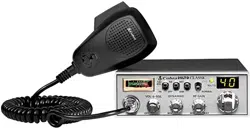
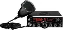
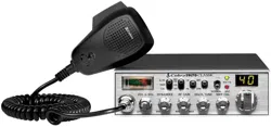
Thank you for purchasing the Cobra 29 LTD AM/FM Pro Series CB Radio
Transceiver. Properly used, this Cobra product will give you many years
of reliable service.
Citizens Band Radio History
Invented by Al Gross in 1945, the CB radio originally served as a method of communication for troops
during World War II. After the war, Gross worked to make two-way radios a way of communication
for personal use and the CB radio service was established by law in the U.S. in 1949. It wasn't until
the 1970s that technology advanced and the CB market caught on as a method of communication
between drivers to report police speed traps and road hazards.
The Citizens Band Radio Service consists of 40 channel frequencies that are mostly 1 0 kHz apart.
Transmitter power is limited to 4 watts in the US, and range can vary depending on the terrain and
quality of the product.
Currently, the Citizens Band service does not require a license for operation, regardless of age, as
long as the rules of operation established by the Federal Communication Commission (FCC) are
followed.
Petition For FCC Part 65 Rule Changes
In 2016, Cobra petitioned the FCC to revise Part 95 rules to allow CB radios to use frequency
modulation (FM). Cobra contended that FM offers improved speech quality and lower noise
interference, which improves the standard of two-way radios and is a benefit to the customer.
Through the direct efforts of Cobra Electronics and the enthusiastic support from loyal customers and
the distribution network the FCC granted the request. In 2021, Part 95 officially was updated to
include FM as an option for two-way radio use.
Today, thanks to Cobra Electronics' petitions to improve the quality of the Citizens Band Radio
Service, users can enjoy the benefits of CB radio communication in a range of industries.
® Customer Support
Should you encounter any problems with this product, not understand its features, menu or
installation, please refer to the this owner's manual. If you require further assistance, after reading this
manual, we are here to help:
Service, Orders & Product Questions
For service, product questions and service hours call 800-543-1608 or go to www.cobra.com
For Assistance Outside the U.S.A.
Contact Your Local Dealer
~
English
~
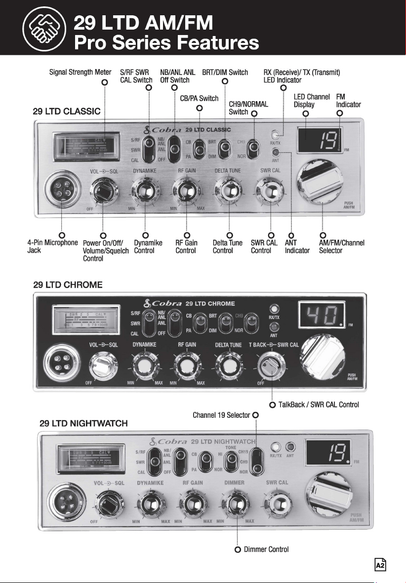
29 LTD AM/FM
~
Pro Series Features
Signal Strength Meter S/RF SWR NB/ANL ANL BRT/DIM Switch RX (Receive)/ TX (Transmit)
LED Indicator o CAL Switch Off Switch o
0 0
1
0
I
29 LTD CLASSIC I
i
b
4-Pin Microphone
Jack
l
6
Power On/Off/
Volume/Squelch
Control
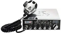
29 LTD CHROME
29 LTD NIGHTWATCH
! CB/PA Switch j cHg/NORMAL
LED Channel FM
O I Switch 0
Display Indicator
9 0
l
b
Dynamike
Control
b
RF Gain
Control
l
b
Delta Tune
Control
I
b
SWRCAL
Control
i
6
ANT
Indicator
AM/FM
I
b
AM/FM/Channel
Selector
0 TalkBack / SWR CAL Control
Channel 19 Selector 0
SIRF
1
$,~'it,ra ::,LTD N:~,~o~;:~,HI () @)
SWR ANL • CH9 RXITX Al
CAL OFF PA NOR NOR •
DYNAMIKE RF GAIN DIMMER SWR CAL
b Dimmer Control
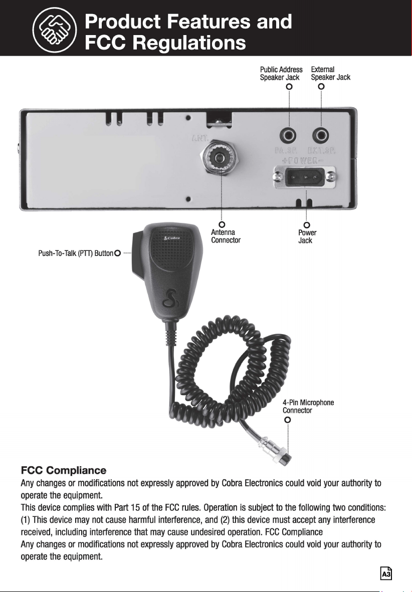
@ Product Features and
~
FCC Regulations
•
Push-To-Talk (PTT) ButtonO •••
FCC Compliance
b
Antenna
Connector
Public Address External
Speaker Jack Speaker Jack
0 0
l
@@
b
Power
Jack
Any changes or modifications not expressly approved by Cobra Electronics could void your authority to
operate the equipment.
This device complies with Part 15 of the FCC rules. Operation is subject to the following two conditions:
(1) This device may not cause harmful interference, and (2) this device must accept any interference
received, including interference that may cause undesired operation. FCC Compliance
Any changes or modifications not expressly approved by Cobra Electronics could void your authority to
operate the equipment.
~
@contents
Our Thanks,The CB Story, Customer Support ..................................................................... A1
Product Features .................................................................................................................... A2.
FCC Regulations ..................................................................................................................... A3
Installation
Location ............................................................................................................................... 2
Mounting and Connection ..................................................................................................... 2
Antennas
Antennas .............................................................................................................................. 4
Operation
Turning On Your CB .............................................................................................................. 5
Setting AM/FM ..................................................................................................................... 5
Setting Channel Selector ...................................................................................................... 5
Calibrate For SWR (Standing Wave Ratio) ............................................................................. 6
To Receive ........................................................................................................................... 8
S-Meter ................................................................................................................................ 8
NB-ANUANUOff (Noise Blanker/Automatic Noise Limiter Switch) ......................................... 8
Bright/Dim Switch ................................................................................................................ 8
RF Gain Control .................................................................................................................... 9
Setting Delta-Tune (29 LTD/29 LTD Chrome) ........................................................................ 9
Setting TalkBack (29 LTD Chrome) ....................................................................................... 9
Dimmer Control (29 LTD NightWatch®) ................................................................................ 9
Setting Squelch .................................................................................................................. 10
To Transmit. ....................................................................................................................... 1 o
Setting Dynamike® ............................................................................................................. 11
RF Meter ............................................................................................................................ 11
External Speaker ................................................................................................................ 11
PA (Public Address) ............................................................................................................ 12
Base Station Operation ....................................................................................................... 13
Temporary Mobile Operation .............................................................................................. 13
How Your CB Can Serve You ................................................................................................ 14
CB 10 Codes ...................................................................................................................... 16
Frequency Ranges .............................................................................................................. 17
29 LTD Classic Specifications ............................................................................................. 18
Warranty Information .......................................................................................................... 19
Need Help? ............................................................................................................................ 20
29 LTD Series Features ........................................................................................................ 21
FCC Statement ....................................................................................................................... 22
® Installation
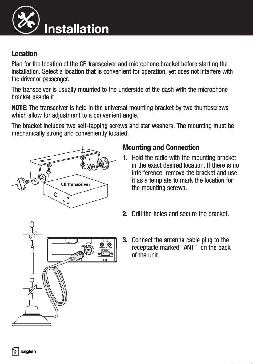
Location
Plan for the location of the CB transceiver and microphone bracket before starting the
installation. Select a location that is convenient for operation, yet does not interfere with
the driver or passenger.
The transceiver is usually mounted to the underside of the dash with the microphone
bracket beside it.
NOTE: The transceiver is held in the universal mounting bracket by two thumbscrews
which allow for adjustment to a convenient angle.
The bracket includes two self-tapping screws and star washers. The mounting must be
mechanically strong and conveniently located.
~
English
Mounting and Connection
1. Hold the radio with the mounting bracket
in the exact desired location. If there is no
interference, remove the bracket and use
it as a template to mark the location for
the mounting screws.
2. Drill the holes and secure the bracket.
3. Connect the antenna cable plug to the
receptacle marked "ANT" on the back
of the unit.
® Installation
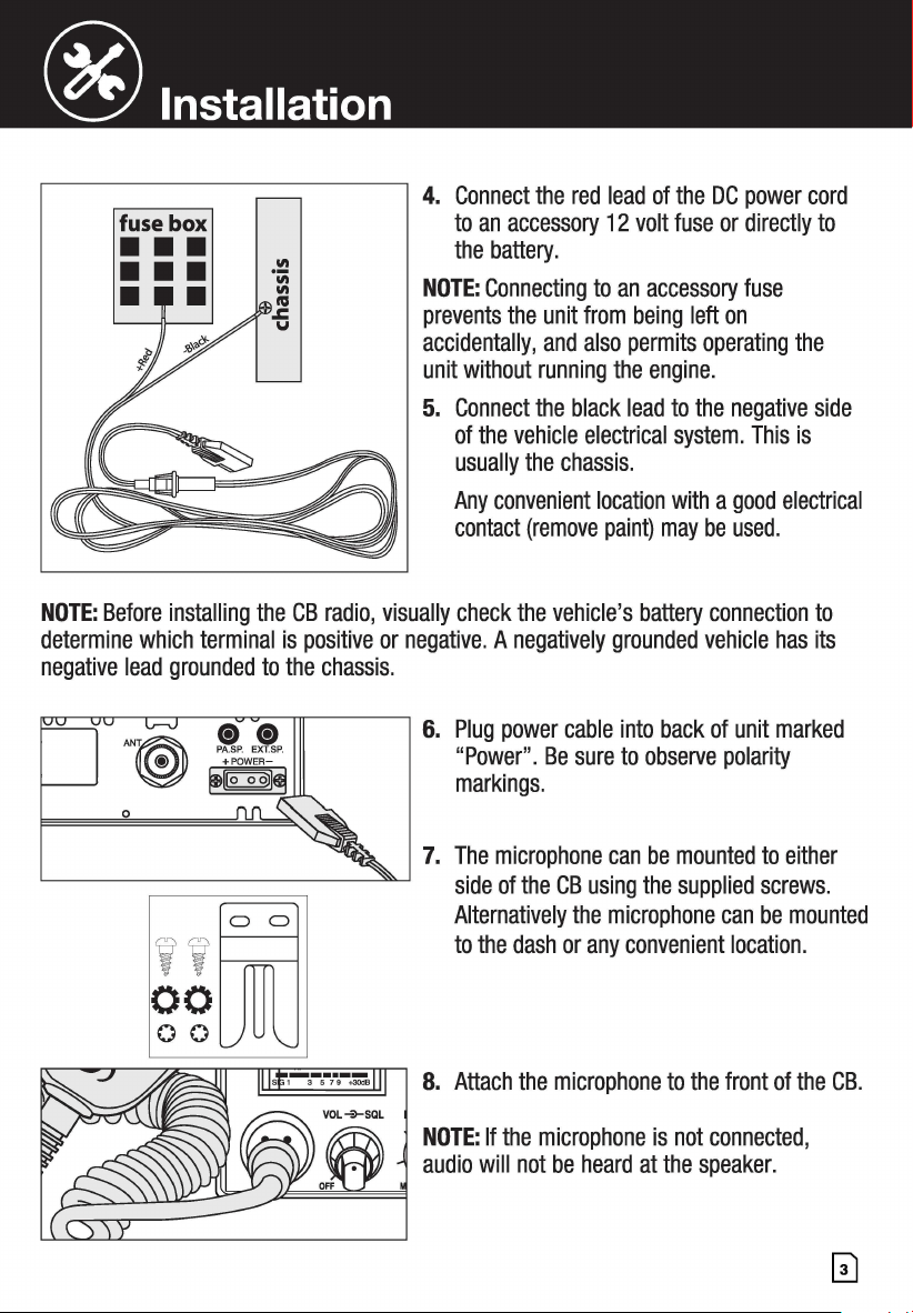
4. Connect the red lead of the DC power cord
to an accessory 12 volt fuse or directly to
the battery.
NOTE: Connecting to an accessory fuse
prevents the unit from being left on
accidentally, and also permits operating the
unit without running the engine.
5. Connect the black lead to the negative side
of the vehicle electrical system. This is
usually the chassis.
Any convenient location with a good electrical
contact (remove paint) may be used.
NOTE: Before installing the CB radio, visually check the vehicle's battery connection to
determine which terminal is positive or negative. A negatively grounded vehicle has its
negative lead grounded to the chassis.
,,;□
00
00
6. Plug power cable into back of unit marked
"Power". Be sure to observe polarity
markings.
7. The microphone can be mounted to either
side of the CB using the supplied screws.
Alternatively the microphone can be mounted
to the dash or any convenient location.
8. Attach the microphone to the front of the CB.
NOTE: If the microphone is not connected,
audio will not be heard at the speaker.
® Antennas
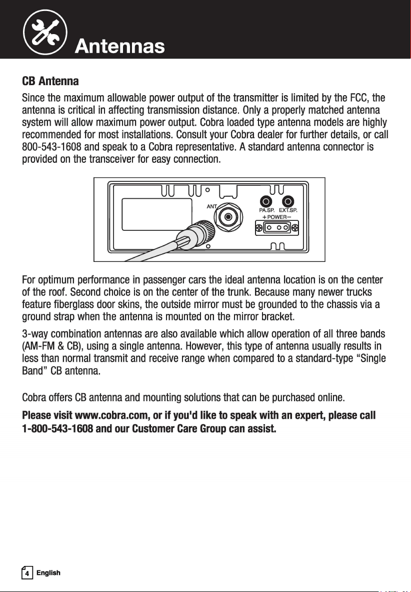
CB Antenna
Since the maximum allowable power output of the transmitter is limited by the FCC, the
antenna is critical in affecting transmission distance. Only a properly matched antenna
system will allow maximum power output. Cobra loaded type antenna models are highly
recommended for most installations. Consult your Cobra dealer for further details, or call
800-543-1608 and speak to a Cobra representative. A standard antenna connector is
provided on the transceiver for easy connection.
For optimum performance in passenger cars the ideal antenna location is on the center
of the roof. Second choice is on the center of the trunk. Because many newer trucks
feature fiberglass door skins, the outside mirror must be grounded to the chassis via a
ground strap when the antenna is mounted on the mirror bracket.
3-way combination antennas are also available which allow operation of all three bands
(AM-FM & CB), using a single antenna. However, this type of antenna usually results in
less than normal transmit and receive range when compared to a standard-type "Single
Band" CB antenna.
Cobra offers CB antenna and mounting solutions that can be purchased online.
Please visit www.cobra.com, or if you'd like to speak with an expert, please call
1-800-543-1608 and our Customer Care Group can assist.
GJ English
@ Operation
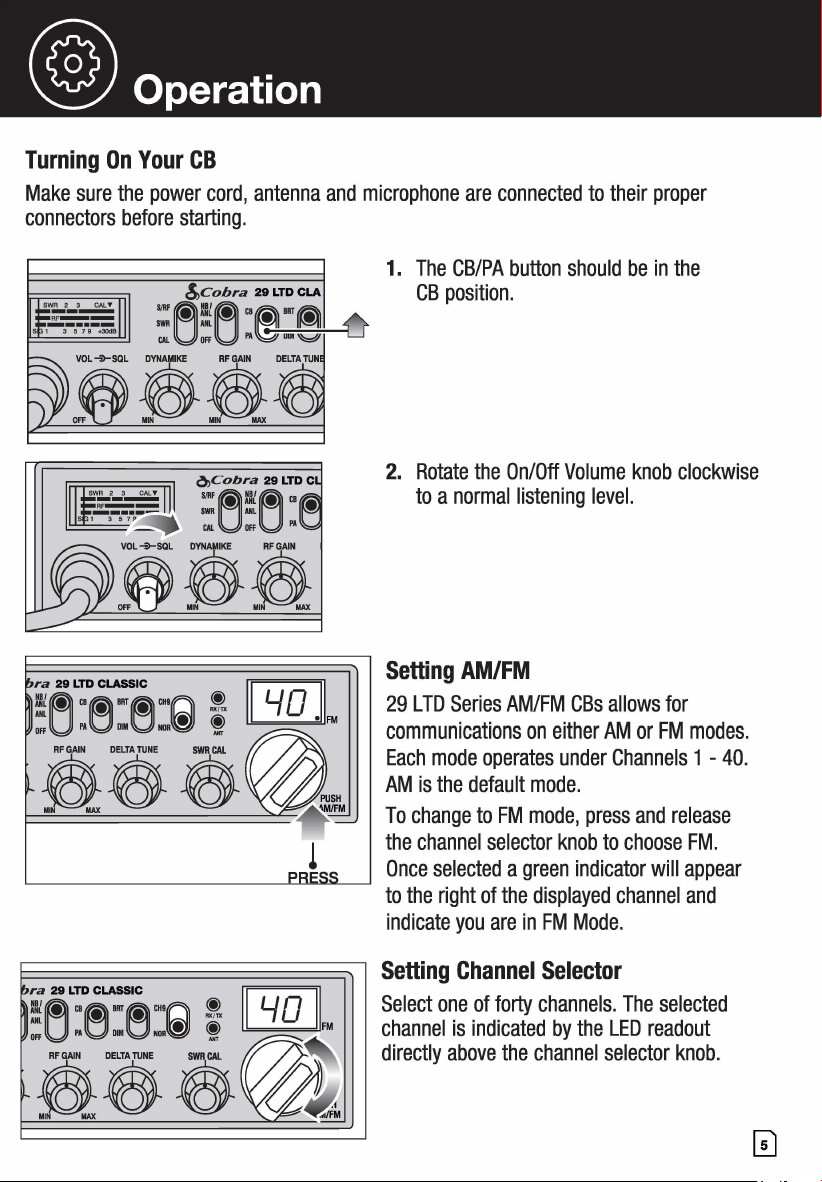
Turning On Your CB
Make sure the power cord, antenna and microphone are connected to their proper
connectors before starting.
ra 29 LTD CLASSIC Gill
:(~Cl~IRT~Cffl~. ! l/0
Dffu .. g .. g ...
~
! • FM
l
trtw1
! lL.2!::!...JFM
1. The CB/PA button should be in the
CB position.
2. Rotate the On/Off Volume knob clockwise
to a normal listening level.
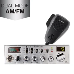
Setting AM/FM
29 LTD Series AM/FM CBs allows for
communications on either AM or FM modes.
Each mode operates under Channels 1 - 40.
AM is the default mode.
To change to FM mode, press and release
the channel selector knob to choose FM.
Once selected a green indicator will appear
to the right of the displayed channel and
indicate you are in FM Mode.
Setting Channel Selector
Select one of forty channels. The selected
channel is indicated by the LED readout
directly above the channel selector knob.
@operation
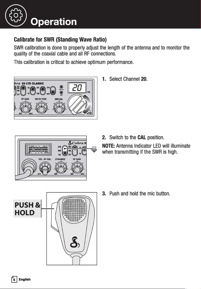
Calibrate for SWR (Standing Wave Ratio)
SWR calibration is done to properly adjust the length of the antenna and to monitor the
quality of the coaxial cable and all RF connections.
This calibration is critical to achieve optimum performance.
ra 29 LTD CLASSIC
~
!i~"MIRTM'"n ! 20
Offu
l'A001
■
0NOR{!JJ
t /,,.----,.:4I ... FM
PUSH&lli
HOLD II~
~
English
1. Select Channel 20.
2. Switch to the CAL position.
NOTE: Antenna Indicator LED will illuminate
when transmitting if the SWR is high.
3. Push and hold the mic button.
@ Operation
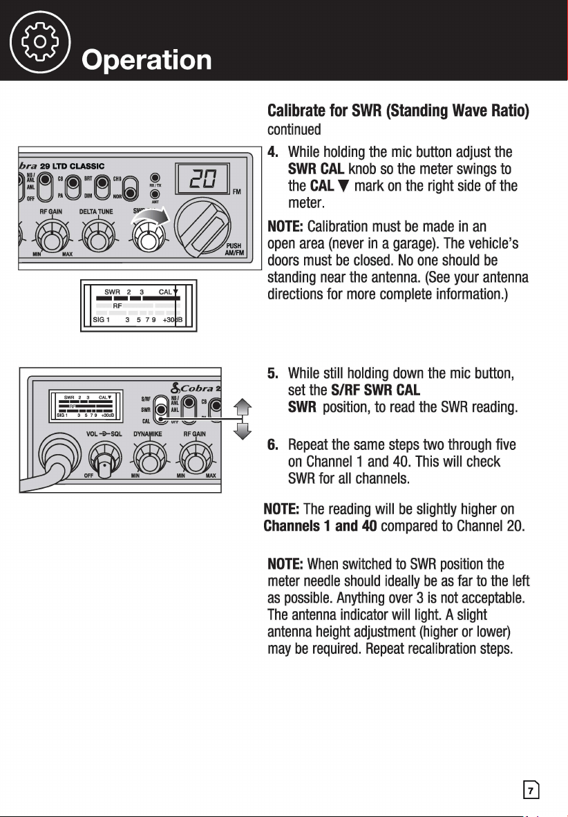
Calibrate for SWR (Standing Wave Ratio)
continued
E~~~~~~~~~~~~~~~~~~~~~~~
4. While holding the mic button adjust the
~----------~
!,,cobra
: i'=:,,;,.~--;;-=:,,,,. __ -1
SWR CAL knob so the meter swings to
the CAL T mark on the right side of the
meter.
NOTE: Calibration must be made in an
open area (never in a garage). The vehicle's
doors must be closed. No one should be
standing near the antenna. (See your antenna
directions for more complete information.)
5. While still holding down the mic button,
set the S/RF SWR CAL
SWR position, to read the SWR reading.
6. Repeat the same steps two through five
on Channel 1 and 40. This will check
SWR for all channels.
NOTE: The reading will be slightly higher on
Channels 1 and 40 compared to Channel 20.
NOTE: When switched to SWR position the
meter needle should ideally be as far to the left
as possible. Anything over 3 is not acceptable.
The antenna indicator will light. A slight
antenna height adjustment (higher or lower)
may be required. Repeat recalibration steps.
@ Operation
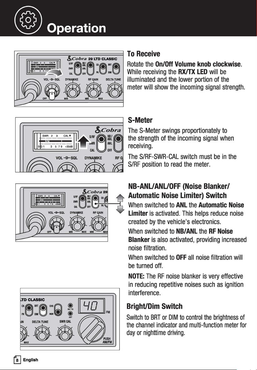
l"r.=====:::::::;=======l To Receive
!,,cobra 29 LTD CLASSIC
:~!~ "~""rti} Rotate the On/Off Volume knob clockwise.
"'U'"U ,.g,.g While receiving the RX/TX LED will be
vo,+-sa, 3 ...... oELr•r••• illuminated and the lower portion of the
"" . "" ft meter will show the incoming signal strength.
S-Meter
The S-Meter swings proportionately to
the strength of the incoming signal when
receiving.
RF The S/RF-SWR-CAL switch must be in the
S/RF position to read the meter.
NB-ANUANUOFF (Noise Blanker/
.,.
~~~~.
Automatic Noise Limiter) Switch
:'U:~l\j" When switched to ANL the Automatic Noise
Limiter is activated. This helps reduce noise
created by the vehicle's electronics.
When switched to NB/ANL the RF Noise
Blanker is also activated, providing increased
noise filtration.
When switched to OFF all noise filtration will
be turned off.
NOTE: The RF noise blanker is very effective
in reducing repetitive noises such as ignition
interference.
TD CLASSIC
t'!J English
Bright/Dim Switch
Switch to BRT or DIM to control the brightness of
the channel indicator and multi-function meter for
day or nighttime driving.
® operation
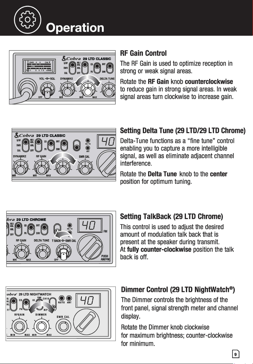
RF Gain Control
The RF Gain is used to optimize reception in
strong or weak signal areas.
Rotate the RF Gain knob counterclockwise
to reduce gain in strong signal areas. In weak
signal areas turn clockwise to increase gain.
~~~~~~~~~~~
Setting TalkBack (29 LTD Chrome)
ifiL:~~~ f'.I\ !. [GQJ] This control is used to adjust the desired
,,.U .. g ,,.g
~
~
™ amount of modulation talk back that is
present at the speaker during transmit.
At fully counter-clockwise position the talk
back is off.
Dimmer Control (29 LTD NightWatch®)
The Dimmer controls the brightness of the
front panel, signal strength meter and channel
display.
Rotate the Dimmer knob clockwise
for maximum brightness; counter-clockwise
for minimum.
@ Operation
&cobra 29 LTD CLASSIC
:el:[:] :e:e
,OL 3 AFGAIN DELTA NE
. , :ft
!,,cobra 29 LTD CLASSIC
=~!(~ "M
1111
M
CALUOFfUPA001
■
0
& ft DELTAruNE
!,,Cobra 29 LTD CLASSIC
... ~:/o!~c,e•"e
IWR ML • •
CAL Off l'A DIM
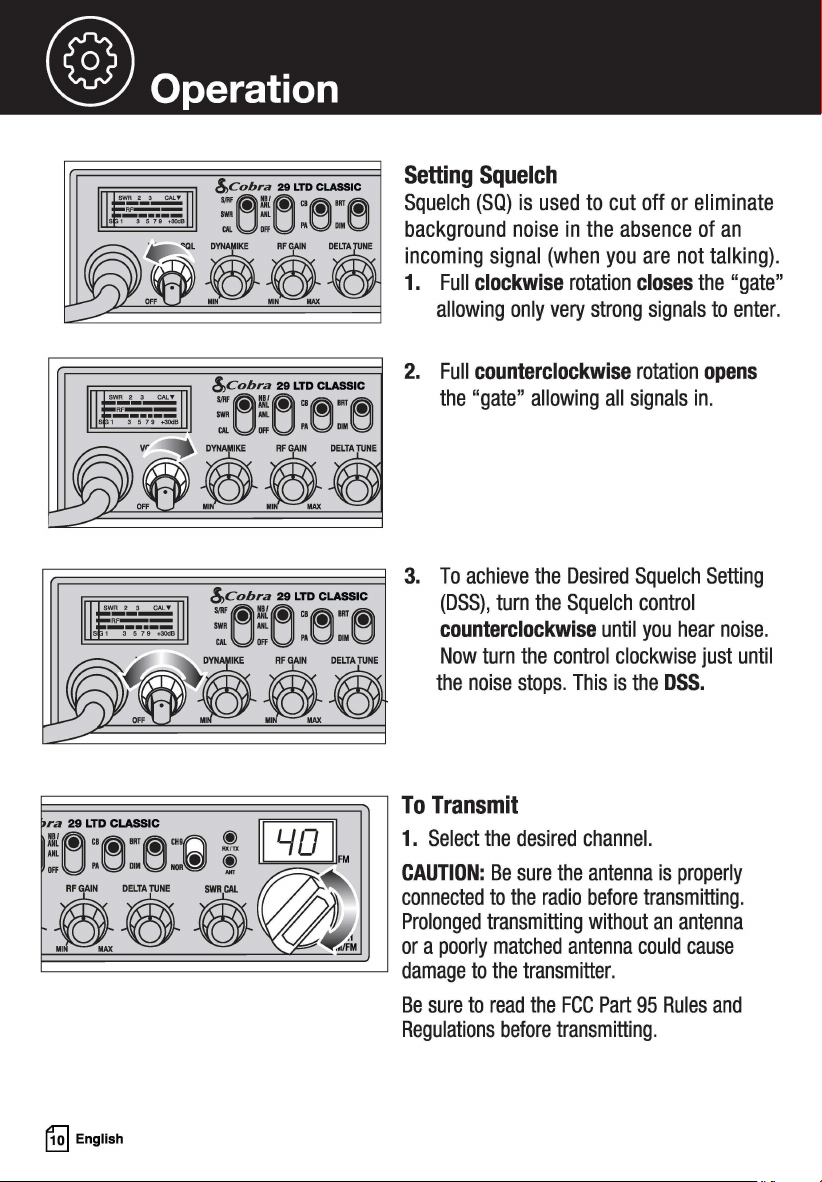
Setting Squelch
Squelch (SQ) is used to cut off or eliminate
background noise in the absence of an
incoming signal (when you are not talking) .
1. Full clockwise rotation closes the "gate"
allowing only very strong signals to enter.
2. Full counterclockwise rotation opens
the "gate" allowing all signals in.
3. To achieve the Desired Squelch Setting
(DSS), turn the Squelch control
counterclockwise until you hear noise.
Now turn the control clockwise just until
the noise stops. This is the DSS.
~~~~~~~~~~7
To Transmit
; G[t
£&33
~~~
ra 29 LTD CLASSIC
!~ "M'"M'"(L))
CffUPAODl
■
Oa~
~
English
1. Select the desired channel.
CAUTION: Be sure the antenna is properly
connected to the radio before transmitting.
Prolonged transmitting without an antenna
or a poorly matched antenna could cause
damage to the transmitter.
Be sure to read the FCC Part 95 Rules and
Regulations before transmitting.
® operation
!,,Cobra 29 LTD CLASSIC
... ~~~"e·"~
IWR ML • •
CM. OFF Pl\ DIM
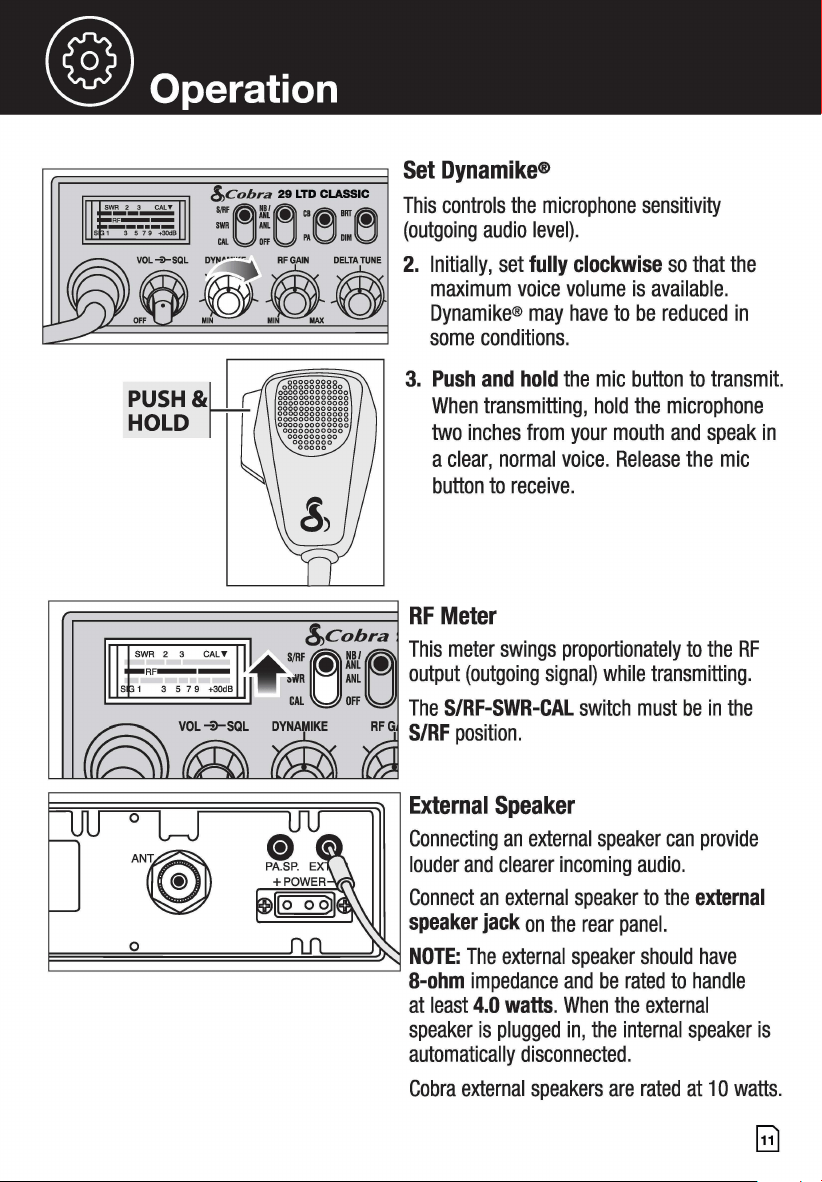
Set Dynamike®
This controls the microphone sensitivity
(outgoing audio level).
2. Initially, set fully clockwise so that the
maximum voice volume is available.
Dynamike® may have to be reduced in
some conditions.
3. Push and hold the mic button to transmit.
When transmitting, hold the microphone
two inches from your mouth and speak in
a clear, normal voice. Release the mic
button to receive.
r.:=============:::::::;;=====1 RF Meter
SJRF!,,~c~
8
~~ra This meter swings proportionately to the RF
•i¥11
~
:t
~
output (outgoing signal) while transmitting.
CAL off The S/RF-SWR-CAL switch must be in the
S/RF position.
~~~~~~~~;;~~~~~~~~~~~~~
External Speaker
Connecting an external speaker can provide
louder and clearer incoming audio.
Connect an external speaker to the external
speaker jack on the rear panel.
E=====o~==========~~~===~~ NOTE: The external speaker should have
8-ohm impedance and be rated to handle
at least 4.0 watts. When the external
speaker is plugged in, the internal speaker is
automatically disconnected.
Cobra external speakers are rated at 1 O watts.
Gl
@ Operation
0
0
PUSH&W
HOLD ITT
~
English
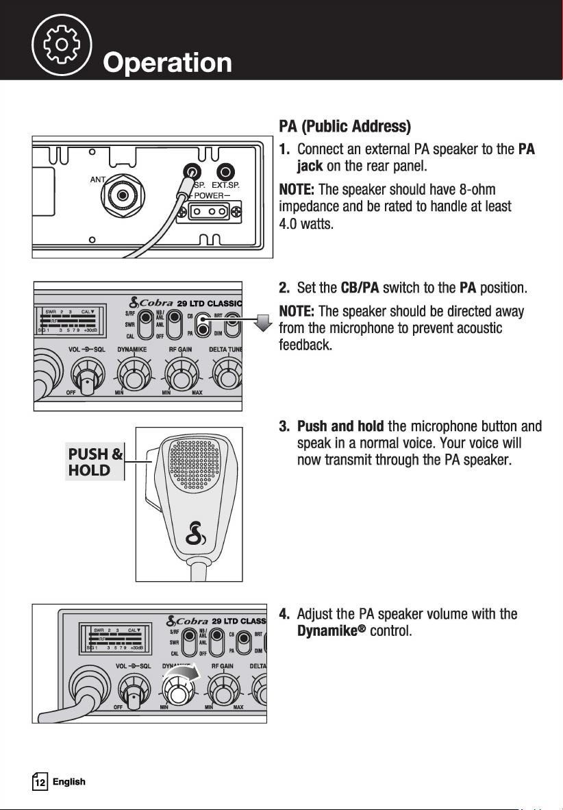
PA (Public Address}
1. Connect an external PA speaker to the PA
jack on the rear panel.
NOTE: The speaker should have 8-ohm
impedance and be rated to handle at least
4.0 watts.
2. Set the CB/PA switch to the PA position.
:f"""L NOTE: The speaker should be directed away
¥ from the microphone to prevent acoustic
feedback.
3. Push and hold the microphone button and
speak in a normal voice. Your voice will
now transmit through the PA speaker.
4. Adjust the PA speaker volume with the
Dynamike® control.
® operation
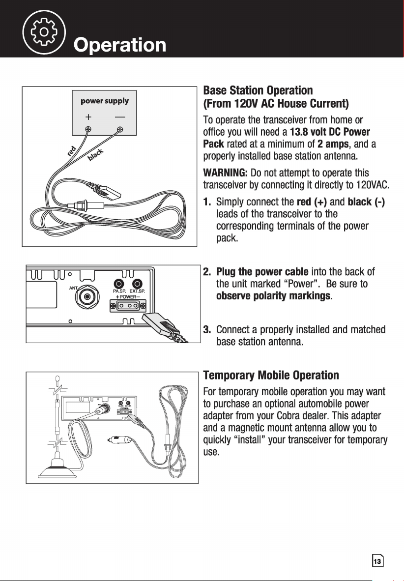
r------;::::::===:::::;----7 Base Station Operation
power supply
+
(From 12OV AC House Current)
To operate the transceiver from home or
office you will need a 13.8 volt DC Power
Pack rated at a minimum of 2 amps, and a
properly installed base station antenna.
WARNING: Do not attempt to operate this
transceiver by connecting it directly to 120VAC.
1. Simply connect the red(+) and black(-)
leads of the transceiver to the
corresponding terminals of the power
pack.
2. Plug the power cable into the back of
the unit marked "Power". Be sure to
observe polarity markings.
3. Connect a properly installed and matched
base station antenna.
Temporary Mobile Operation
For temporary mobile operation you may want
to purchase an optional automobile power
adapter from your Cobra dealer. This adapter
and a magnetic mount antenna allow you to
quickly "install" your transceiver for temporary
use.
~
(® How Your CB Can Serve You
Your CB Radio Can:
• Warn of traffic problems
• Provide weather and road data
• Provide help in event of an emergency
• Provide direct contact with home or office
• Assist police by reporting erratic drivers
• Get "local information" to find destination
• Communicate with family and friends
• Suggest spots to eat and sleep
• Keep you alert while traveling
A Few Rules You Should Know:
A. Conversations cannot last more than 5 minutes with another station. A one minute
break is required to let others use the channel.
B. You cannot blast others off the air by use of illegally amplified transmitters or illegally
high antennas.
C. You cannot use CB to promote illegal activities.
D. Profanity is not allowed.
E. You may not transmit music with a CB.
F. Selling of merchandise and/or services is prohibited.
Set Channel 9 For Emergencies
Be sure antenna is properly connected.
CB Distress Data
When transmitting an emergency, you should request a "REACT BASE" and provide the CB
distress data (called CLIP):
C all Sign Identify yourself.
L ocation Be exact.
I njuries Number. Type. Trapped?
P roblem Give details and help needed.
Transmit CLIP repeatedly so any monitor can assist.
NOTE: If no response on channel 9, try channels 19 or 14.
~
English
@ How Your CB Can Serve You
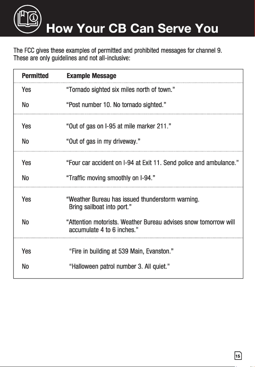
The FCC gives these examples of permitted and prohibited messages for channel 9.
These are only guidelines and not all-inclusive:
Permitted
Yes
No
Yes
No
Yes
No
Yes
No
Yes
No
Example Message
"Tornado sighted six miles north of town."
"Post number 10. No tornado sighted."
"Out of gas on 1-95 at mile marker 211."
"Out of gas in my driveway."
"Four car accident on 1-94 at Exit 11. Send police and ambulance."
"Traffic moving smoothly on 1-94."
"Weather Bureau has issued thunderstorm warning.
Bring sailboat into port."
"Attention motorists. Weather Bureau advises snow tomorrow will
accumulate 4 to 6 inches."
"Fire in building at 539 Main, Evanston."
"Halloween patrol number 3. All quiet."
@ CB 10-Codes
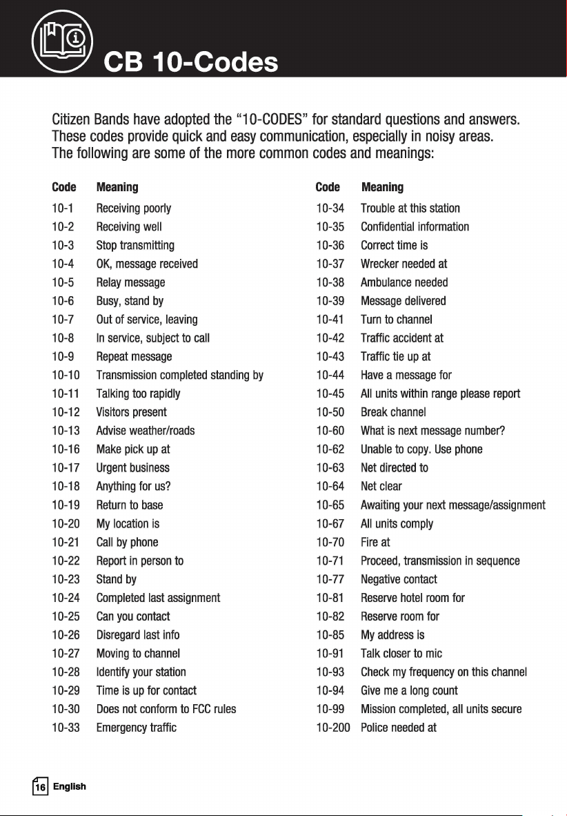
Citizen Bands have adopted the "10-CODES" for standard questions and answers.
These codes provide quick and easy communication, especially in noisy areas.
The following are some of the more common codes and meanings:
Code
Meaning
Code
Meaning
10-1 Receiving poorly 10-34
Trouble at this station
10-2 Receiving well 10-35
Confidential information
10-3 Stop transmitting 10-36 Correct time is
10-4 OK, message received 10-37
Wrecker needed at
10-5 Relay message 10-38
Ambulance needed
10-6 Busy, stand by 10-39 Message delivered
10-7 Out of service, leaving 10-41 Turn to channel
10-8 In service, subject to call 10-42
Traffic accident at
10-9 Repeat message 10-43 Traffic tie up at
10-10 Transmission completed standing by 10-44 Have a message for
10-11 Talking too rapidly 10-45 All units within range please report
10-12
Visitors present 10-50 Break channel
10-13
Advise weather/roads
10-60 What is next message number?
10-16 Make pick up at 10-62 Unable to copy. Use phone
10-17
Urgent business 10-63 Net directed to
10-18 Anything for us? 10-64
Net clear
10-19
Return to base
10-65 Awaiting your next message/assignment
10-20 My location is 10-67 All units comply
10-21 Call by phone 10-70
Fire at
10-22 Report in person to 10-71 Proceed, transmission in sequence
10-23 Stand by
10-77
Negative contact
10-24 Completed last assignment 10-81
Reserve hotel room for
10-25 Can you contact 10-82
Reserve room for
10-26 Disregard last info 10-85 My address is
10-27 Moving to channel 10-91 Talk closer to mic
10-28 Identify your station 10-93 Check my frequency on this channel
10-29 Time is up for contact 10-94 Give me a long count
10-30
Does not conform to FCC rules
10-99 Mission completed, all units secure
10-33 Emergency traffic 10-200
Police needed at
~
English
~
Frequency Ranges
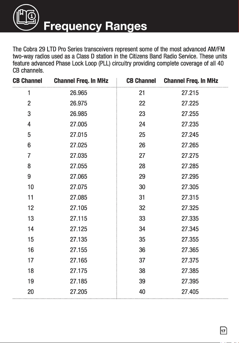
The Cobra 29 LTD Pro Series transceivers represent some of the most advanced AM/FM
two-way radios used as a Class D station in the Citizens Band Radio Service. These units
feature advanced Phase Lock Loop (PLL) circuitry providing complete coverage of all 40
CB channels.
CB Channel
2 26.975 22 27.225
3 26.985 23 27.255
4 27.005 24 27.235
5 27.015 25 27.245
6
27.025 26 27.265
7 27.035 27 27.275
8 27.055 28 27.285
9 27.065 29 27.295
10 27.075 30 27.305
11 27.085 31 27.315
12 27.105 32 27.325
13
27.115
33
27.335
14 27.125 34 27.345
15 27.135 35
27.355
16 27.155
36
27.365
17 27.165 37 27.375
18
27.175
38
27.385
27.185
39
27.395
3.23 lbs.
10.08” D x 7.28” W x 2.20” H
@ Specifications
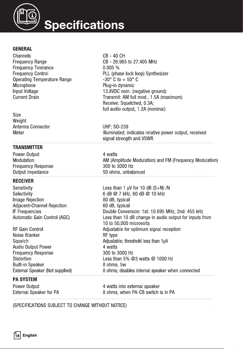
GENERAL
Channels
Frequency Range
Frequency Tolerance
Frequency Control
Operating Temperature Range
Microphone
Input Voltage
Current Drain
Size
Weight
Antenna Connector
Meter
TRANSMITTER
Power Output
Modulation
Frequency Response
Output Impedance
RECEIVER
Sensitivity
Selectivity
Image Rejection
Adjacent-Channel Rejection
IF Frequencies
Automatic Gain Control (AGC)
RF Gain Control
Noise Blanker
Squelch
Audio Output Power
Frequency Response
Distortion
Built-in Speaker
External Speaker (Not supplied)
PA SYSTEM
Power Output
External Speaker for PA
CB-40CH
CB - 26.965 to 27.405 MHz
0.005 %
PLL (phase lock loop) Synthesizer
-30° C to
+ 50° C
Plug-in dynamic
13.BVDC nom. (negative ground)
Transmit: AM full mod., 1.5A (maximum)
Receive: Squelched, 0.3A;
full audio output, 1.2A (nominal)
UHF; S0-239
Illuminated; indicates relative power output, received
signal strength and VSWR
4 watts
AM (Amplitude Modulation) and FM (Frequency Modulation)
300 to 3000 Hz
50 ohms, unbalanced
Less than 1 µV for 10 dB (S+N) /N
6 dB @ 7 kHz, 60 dB @ 10 kHz
80 dB, typical
60 dB, typical
Double Conversion: 1st: 10.695 MHz, 2nd: 455 kHz
Less than 10 dB change in audio output for inputs from
10 to 50,000 microvolts
Adjustable for optimum signal reception
RF type
Adjustable; threshold less than 1 µV
4 watts
300 to 3000 Hz
Less than 5% @3 watts @ 1000 Hz
8 ohms, 5w
8 ohms; disables internal speaker when connected
4 watts into external speaker
8 ohms, when PA-CB switch is in PA
(SPECIFICATIONS SUBJECT TO CHANGE WITHOUT NOTICE)
~
English
~
Limited 2-Year Warranty
Warranty Terms:
Cobra warrants your product against all defects in materials and workmanship for a period of two
(2) years from the date of original purchase.
Cobra, at our sole discretion, will repair or replace your product (with the same or comparable
product) free of charge.
Cobra will not pay shipping charges that you incur for sending your product to us. Products
received COD will be refused.
To make a warranty claim, we will require proof or purchase in the form of an invoice or receipt.
No proof of purchase is required for factory direct purchases.
Warranty Exclusions: Warranty does not apply to your product under any of the following
conditions: 1. The serial number has been removed or modified. 2. Your product has been
subjected to misuse or damage (including water damage, physical abuse, and/or improper
installation). 3. Your product has been modified in any way. 4. Your receipt or proof-of-purchase
is from a non-authorized dealer or internet auction site including E-bay, U-bid, or other non-
authorized resellers.
LIMITATION OF WARRANTY: EXCEPT AS EXPRESSLY PROVIDED HEREIN, YOU ARE ACQUIRING
THE PRODUCT "AS IS" AND "WHERE IS", WITHOUT REPRESENTATION OR WARRANTY. COBRA
SPECIFICALLY DISCLAIMS ANY REPRESENTATION OR WARRANTY INCLUDING, BUT NOT
LIMITED TO THOSE CONCERNING THE MERCHANTABILITY AND SUITABILITY OF THE PRODUCT
FOR A PARTICULAR PURPOSE. COBRA SHALL NOT BE LIABLE FOR CONSEQUENTIAL, SPECIAL
OR INCIDENTAL DAMAGES INCLUDING, WITHOUT LIMITATION, DAMAGES ARISING OUT OF THE
USE, MISUSE OR MOUNTING OF THE PRODUCT.
The above limitations or exclusions shall be limited to the extent they violate the laws of any
particular state. Cobra is not responsible for products lost in shipment between the owner and our
service center.
General Warranty Information
Each product we manufacture is covered by our factory warranty. While each product may have
unique components and policy, the general guideline below will apply to most Cobra products.
All Cobra products purchased factory-direct or from our Authorized Resellers will come with a full
one to three (1-3) year warranty from the date of the original retail purchase (see policy statement
above for full warranty details and exclusions).
Standard accessories packaged with each model will have a one-year factory warranty.
Accessory items have a one-year factory warranty.
Shipping to our facility is not covered in our warranty. Return shipping is included within
the US.
This warranty is non-transferrable.
For the sake of clarity, 'repair or replace the Product or its defective part' does not include
removal or installation work, costs or expenses which include but are not limited to labor costs or .
expenses.
Cobra will not be responsible for lost packages.
@) Need Help?
If you have any questions about operation or installing your new Cobra product, PLEASE
CONTACT COBRA FIRST ... do not return this product to any retail store.
The contact information for Cobra will vary depending on the country in which you
purchased and utilize the product. For the latest contact information, please go to www.
cobra.com/support
For products purchased in the U.S.A. you may call 800-543-1608.
Should there be any problems with this product or further information is needed
on its features please visit www.cobra.com for support, frequently asked questions,
Declarations of Conformity, and full manuals.
For Products Purchased Outside the U.S.A. or Canada
Please contact your local dealer for product service information.
~
English
~
29 LTD Series Features
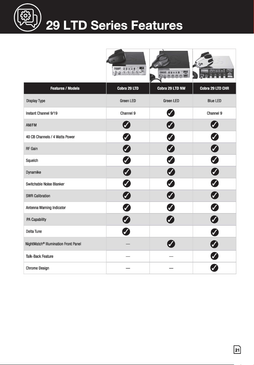
Features / Models Cobra 29 LTD Cobra 29 LTD NW Cobra 29 LTD CHR
Display Type G LED reen G LED reen Bl LED
ue
Instant Channe 19/19 Channel 9
0
Channel 9
AM/FM
0
0
0
40 CB Channe Is / 4 Watts Power
0
0
0
RF Gain
0
0 0
Squelch
0
0
0
Dynamike
0
0
0
Switchable No ise Blanker
0
0
0
SWR Calibratio n
0
0
0
Antenna Wami ng Indicator
0
0 0
PA Capability
0
0 0
Delta Tune
0
0
NightWatch® II
lumination Front Panel
-
0
0
Talk-Back Featu
re
- -
0
Chrome Design
- -
0
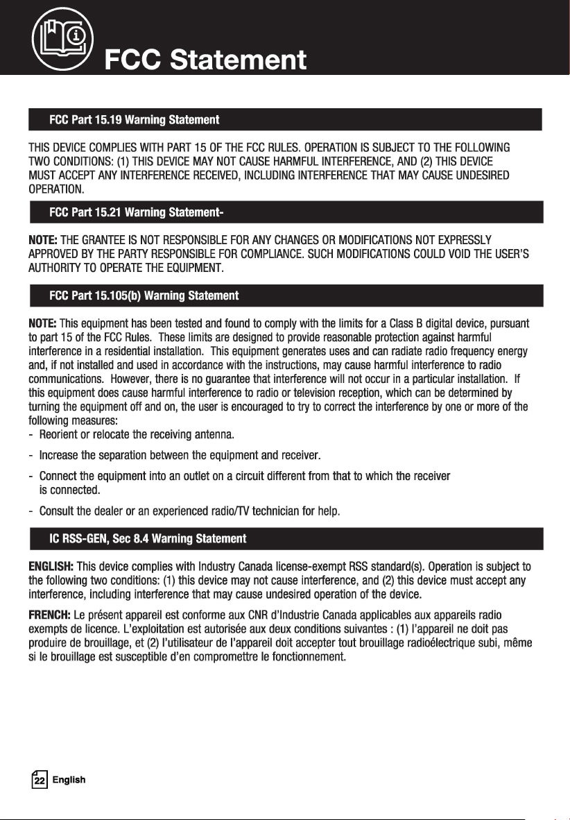
@ FCC Statement
FCC Part 15.19 Warning Statement
THIS DEVICE COMPLIES WITH PART 15 OF THE FCC RULES. OPERATION IS SUBJECT TO THE FOLLOWING
TWO CONDITIONS: (1) THIS DEVICE MAY NOT CAUSE HARMFUL INTERFERENCE, AND (2) THIS DEVICE
MUST ACCEPT ANY INTERFERENCE RECEIVED, INCLUDING INTERFERENCE THAT MAY CAUSE UNDESIRED
OPERATION.
FCC Part 15.21 Warning Statement-
NOTE: THE GRANTEE IS NOT RESPONSIBLE FOR ANY CHANGES OR MODIFICATIONS NOT EXPRESSLY
APPROVED BY THE PARTY RESPONSIBLE FOR COMPLIANCE. SUCH MODIFICATIONS COULD VOID THE USER'S
AUTHORITY TO OPERATE THE EQUIPMENT.
FCC Part 15.105(b) Warning Statement
NOTE: This equipment has been tested and found to comply with the limits for a Class B digital device, pursuant
to part 15 of the FCC Rules. These limits are designed to provide reasonable protection against harmful
interference in a residential installation. This equipment generates uses and can radiate radio frequency energy
and, if not installed and used in accordance with the instructions, may cause harmful interference to radio
communications. However, there is no guarantee that interference will not occur in a particular installation. If
this equipment does cause harmful interference to radio or television reception, which can be determined by
turning the equipment off and on, the user is encouraged to try to correct the interference by one or more of the
following measures:
- Reorient or relocate the receiving antenna.
- Increase the separation between the equipment and receiver.
- Connect the equipment into an outlet on a circuit different from that to which the receiver
is connected.
- Consult the dealer or an experienced radio/TV technician for help.
IC RSS-GEN, Sec 8.4 Warning Statement
ENGLISH: This device complies with Industry Canada license-exempt RSS standard(s). Operation is subject to
the following two conditions: (1) this device may not cause interference, and (2) this device must accept any
interference, including interference that may cause undesired operation of the device.
FRENCH: Le present appareil est conforme aux CNR d'lndustrie Canada applicables aux appareils radio
exempts de licence. L'exploitation est autorisee aux deux conditions suivantes: (1) l'appareil ne doit pas
produire de brouillage, et (2) l'utilisateur de l'appareil doit accepter tout brouillage radioelectrique subi, meme
si le brouillage est susceptible d'en compromettre le fonctionnement.
~
English
@ FCC Statement
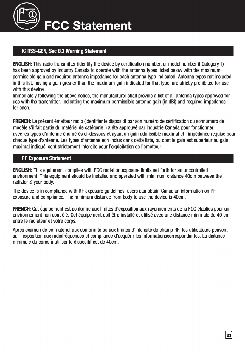
IC RSS-GEN, Sec 8.3 Warning Statement
ENGLISH: This radio transmitter (identify the device by certification number, or model number if Category II)
has been approved by Industry Canada to operate with the antenna types listed below with the maximum
permissible gain and required antenna impedance for each antenna type indicated. Antenna types not included
in this list, having a gain greater than the maximum gain indicated for that type, are strictly prohibited for use
with this device.
Immediately following the above notice, the manufacturer shall provide a list of all antenna types approved for
use with the transmitter, indicating the maximum permissible antenna gain (in dBi) and required impedance
for each.
FRENCH: Le present emetteur radio (identifier le dispositif par son numero de certification ou sonnumero de
modele s'il fait partie du materiel de categorie I) a ete approuve par lndustrie Canada pour fonctionner
avec les types d'antenne enumeres ci-dessous et ayant un gain admissible maximal et !'impedance requise pour
chaque type d'antenne. Les types d'antenne non inclus dans cette liste, ou dont le gain est superieur au gain
maximal indique, sont strictement interdits pour !'exploitation de l'emetteur.
RF Exposure statement
ENGLISH: This equipment complies with FCC radiation exposure limits set forth for an uncontrolled
environment. This equipment should be installed and operated with minimum distance 40cm between the
radiator & your body.
The device is in compliance with RF exposure guidelines, users can obtain Canadian information on RF
exposure and compliance. The minimum distance from body to use the device is 40cm.
FRENCH: Cet equipement est conforme aux limites d'exposition aux rayonnements de la FCC etablies pour un
environnement non controle. Cet equipement doit etre installe et utilise avec une distance minimale de 40 cm
entre le radiateur et votre corps.
Aprils examen de ce materiel aux conformite ou aux limites d'intensite de champ RF, les utilisateurs peuvent
sur !'exposition aux radiofrequences et compliance d'acquerir les informationscorrespondantes. La distance
minimale du corps a utiliser le dispositif est de 40cm.

NOTES
~
English

NOTES
5
AW-1210077-1B
For more information or to order any of our
products, please visit our website: www.cobra.com
©202 Cobra Electronics Corporation
Cobra®, Dynamike®, Nothing Comes Close to a Cobra® and the snake design are registered
trademarks of Cobra Electronics Corporation, USA.
Cobra Electronics Corporation™ is a trademark of Cobra Electronics Corporation, USA.
Pat. www.cobra.com/patents