
Visit our website at: http://www.harborfreight.com
Email our technical support at: [email protected]
55
00
Owner’s Manual & Safety Instructions
Save This Manual Keep this manual for the safety warnings and precautions, assembly,
operating, inspection, maintenance and cleaning procedures. Write the product’s serial number in the
back of the manual near the assembly diagram (or month and year of purchase if product has no number).
Keep this manual and the receipt in a safe and dry place for future reference. 21e
When unpacking, make sure that the product is intact
and undamaged. If any parts are missing or broken,
please call 1-888-866-5797 as soon as possible.
Copyright
©
2020 by Harbor Freight Tools
®
. All rights reserved.
No portion of this manual or any artwork contained herein may be reproduced in
any shape or form without the express written consent of Harbor Freight Tools.
Diagrams within this manual may not be drawn proportionally. Due to continuing
improvements, actual product may differ slightly from the product described herein.
Tools required for assembly an d se rv ic e may n ot b e in cl uded.
Read this material before using this product.
Failure to do so can result in serious injury.
SAVE THIS MANUAL.
Page 2 For technical questions, please call 1-888-866-5797. Item 57535
Rated Single
Line Pull
5500 lb (2494 kg)
Application ATV/UTV
Motor 12 VDC 1.5 HP Permanent Magnet
Power IN &
Power OUT
Yes
Duty Cycle Rating
5% (45 sec at Max Rated Load;
14 min, 15 sec Rest)
Remote Control Wired, 10 ft (3 m) long
Dash Rocker Switch Wired, 4 ft (1.2 m) long
Geartrain 3-Stage Planetary
Gear Ratio 201:1
Freespool Cam Activated
Brake Auto. Load Holding Mechanical
Drum (Dia. x L) 2.36″ x 5.16″ (60 mm x 131 mm)
Hook
5/16″ Clevis, with
Spring-loaded Safety Latch
Fairlead Aluminum Hawse
Synthetic Rope
Size / Type
Ø1/4″ x 50′ (Ø6.3 mm x 15.2 m)
Battery 12 VDC, Minimum 12 Ah
Battery Cables 6 gauge, 3′ (0.9 m) long
Solenoid Cables 6 gauge, 8′ (2.4 m) long
Mounting Pattern 3″ x 6.6″ (76.2 mm x 167.8 mm)
Mounting Hardware Winch:
4 x G8, M8-1.25 x 25 mm
Adaptor Plate:
2 x G8, M8-1.25 x 25 mm
Fairlead:
2 x G8, M8-1.25 x 20 mm
Socket Lead:
2 x G8, ST-M4 x 30 mm
Sound Rating 85 dB
Overall Dimensions
(L x D x H)
15.87″ x 4.72″ x 5.0″
(403 x 120 x 127 mm)
Weight 20.78 lb (9.4 kg)
IP Rating
IP 68 – Winch and Controls
(except remote switch,
resistant to powerful water jets)
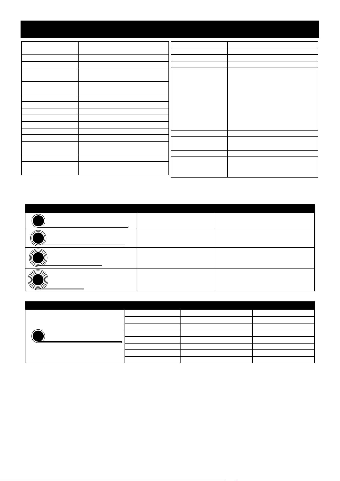
Layer Rated Line Pull Synthetic Rope Capacity
1
5500 lb (2494 kg) 12.9′ (3.94 m)
2
4654 lb (2111 kg) 28.2′ (8.59 m)
3
4033 lb (1829 kg) 45.8′ (13.97 m)
4
3559 lb (1614 kg) 50.0′ (15.24 m)
First Layer of Synthetic Rope Performance
1
Line Pull lb (kg) Line Speed fpm (mpm) Amp Draw (
@
12V)
0 (0) 18.7 (5.7) 31
500 (227) 16.3 (4.9) 51
1500 (680) 15.0 (4.5) 88
2500 (1134) 13.5 (4.1) 126
3500 (1587) 11.4 (3.4) 171
4500 (2041) 10.1 (3.0) 218
5500 (2495) 7.9 (2.4) 291
Specifications
Page 3For technical questions, please call 1-888-866-5797.Item 57535
SAFETYOPERATIONMAINTENANCE SETUP
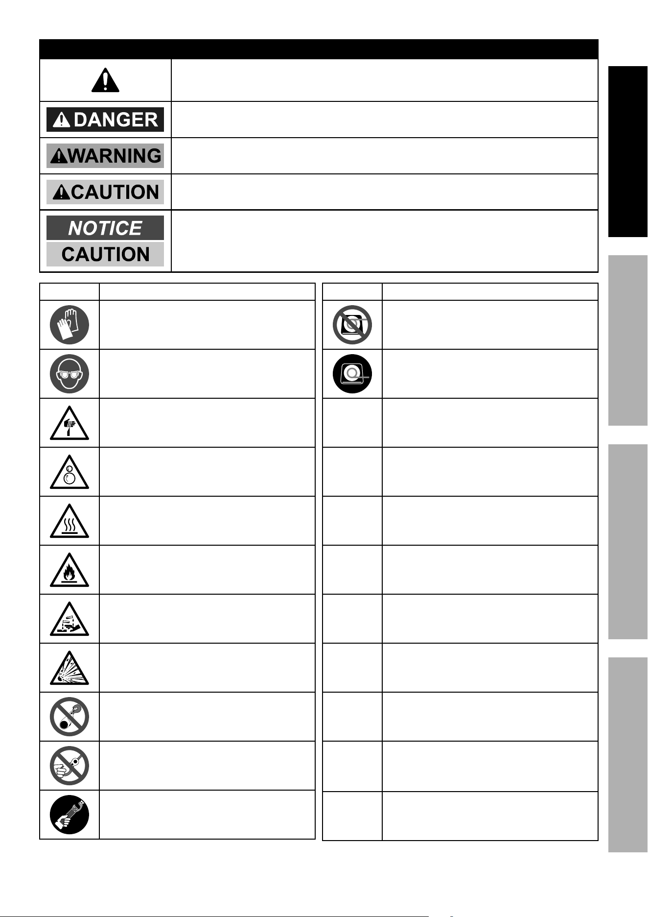
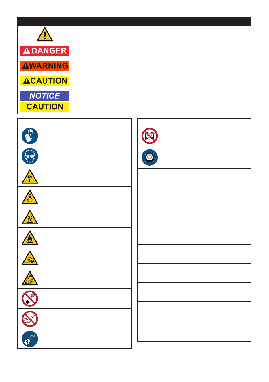
WARNING SYMBOLS AND DEFINITIONS
This is the safety alert symbol. It is used to alert you to potential
personal injury hazards. Obey all safety messages that
follow this symbol to avoid possible injury or death.
Indicates a hazardous situation which, if not avoided,
will result in death or serious injury.
Indicates a hazardous situation which, if not avoided,
could result in death or serious injury.
Indicates a hazardous situation which, if not avoided,
could result in minor or moderate injury.
Addresses practices not related to personal injury.
Symbol Property or Statement
Wear heavy-duty, cut- and
abrasion-resistant leather gloves.
Wear ANSI-approved safety glasses.
Cut or sever hazard.
Roller entanglement hazard.
Hot surface burn hazard.
Fire hazard.
Caustic chemical (acid) hazard.
Explosion hazard.
Do not loop the synthetic rope around
object and hook onto itself.
Do not place finger(s) through hook.
Fingers may be caught and get
pulled into fairlead or drum.
Pull hook using strap only.
Symbol Property or Statement
Do not use winch in overwind orientation.
(Rope enters/exits at the top.)
Use winch only in underwind orientation.
(Rope enters/exits at the bottom.)
VDC
Volts Direct Current
A
Amperes
CCA
Cold Cranking Amperes
HP
Horsepower
fpm
Feet Per Minute
mpm
Meters Per Minute
RPM
Revolutions Per Minute
IP
International Protection rating
Classifies the degrees of protection provided
against the intrusion of solid objects,
dust, accidental contact, and water.
G8
Grade 8
A fastener strength rating.

Page 4 For technical questions, please call 1-888-866-5797. Item 57535
SAFETY OPERATION MAINTENANCESETUP
Important Safety Information
WARNING! Read all instructions.
Failure to follow all instructions may result in fire, serious injury and/or DEATH.
The warnings and precautions discussed in this manual cannot cover all possible conditions and
situations that may occur. It must be understood by the operator that common sense and caution
are factors which cannot be built into this product, but must be supplied by the operator.
Installation Precautions
1. Do not wear loose clothing or jewelry,
as they can be caught in moving parts.
Non-skid footwear is recommended.
Wear restrictive hair covering to contain long hair.
2. Wear ANSI-approved safety goggles and
heavy-duty leather work gloves during installation.
3. Before installation confirm that area is clear
of fuel lines, brake lines, electrical wires,
gas tanks or any other component which
could be damaged during drilling.
4. Mounting location and hardware
must support winch and load.
5. Use supplied power cords and synthetic rope
listed in manual only. Do not use thinner/
longer cables or link multiple cables together.
6. Do not route electrical cables near sharp edges
or parts that will move or become hot.
7. Ventilate area well before and while working
on battery. Explosive invisible hydrogen gas
can accumulate and then explode when ignited
by a spark from the battery connection.
8. Only connect to a clean, corrosion free battery.
9. Do not lean over or come in contact with
battery while making connections.
10. Remove all metal jewelry before
working near battery.
11. Connect red wire to positive battery terminal
and black wire to negative battery terminal.
12. Insulate all exposed wiring and
terminals after installation.
13. Install winch and fairlead in underwind orientation,
so that the synthetic rope enters and exits
the winch at the bottom of the drum.
Page 5For technical questions, please call 1-888-866-5797.Item 57535
SAFETYOPERATIONMAINTENANCE SETUP
Operation Precautions
1. Do not exceed load capacity. Be aware of
dynamic loading! Sudden load movement may
briefly create excess load causing product failure.
2. Do not maintain power to the winch if the motor
stalls. Verify load is within rated capacity for
the synthetic rope layer — see Specifications on
page 2. Make sure the battery is fully charged.
Use double line rigging whenever possible.
Refer to Double Line Rigging on page 11.
3. Wear ANSI-approved safety goggles and
heavy-duty leather work gloves during operation.
4. Do not disengage clutch under load.
Engage clutch before starting.
5. Keep clear of fairlead when operating.
Do not try to guide synthetic rope.
6. Do not place finger(s) through hook or shackle.
Fingers may be caught and get pulled into fairlead
or drum. Use included strap to hold hook instead.
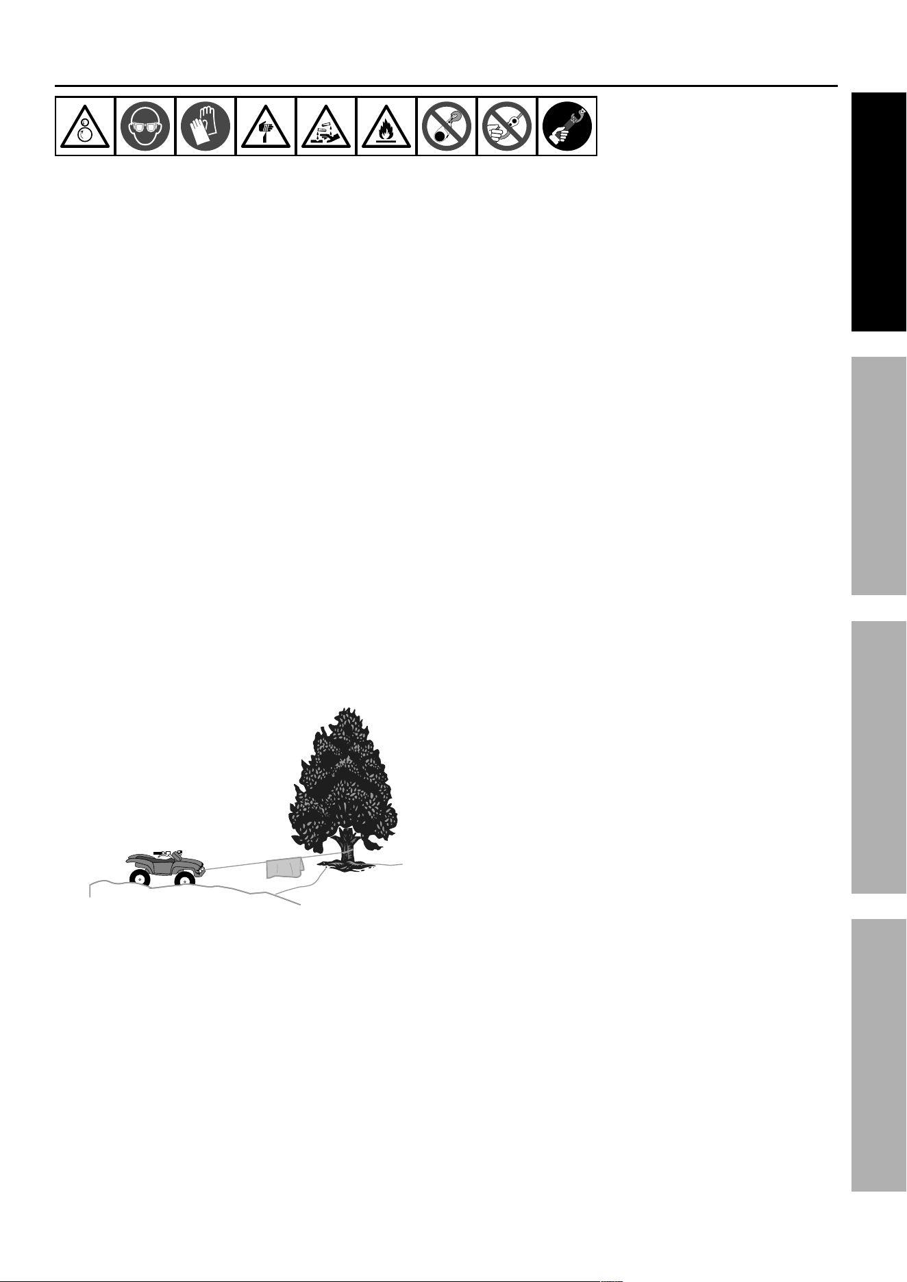
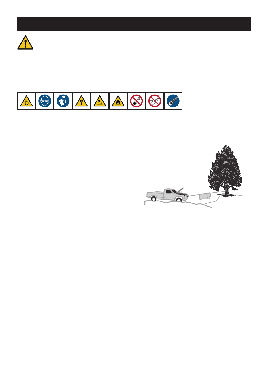
7. Stay out of the direct line that the synthetic rope
is pulling. If it slips or breaks, it will “whiplash”
along this line. Place a heavy blanket or winch
damper over the synthetic rope span 6 feet
from hook to help absorb the force released if
the synthetic rope breaks. Refer to Figure A.
Figure A: Whiplash Dampening
Blanket or Winch Damper
8. Do not use for lifting or moving people.
9. Use a spotter to assist you in ensuring that it
is safe to operate the winch. Make sure the
spotter is out of the way of the vehicle and the
synthetic rope before activating the winch.
10. Do not use the hand crank, if equipped,
to “assist” the winch.
11. Do not use vehicle to pull on the
synthetic rope and “assist” the winch.
12. Use as intended only.
Do not lift items vertically or use
for aircraft purposes.
13. Prevent entanglement. Do not wear loose clothing
or jewelry, as they can be caught in moving parts.
Non-skid footwear is recommended. Wear restrictive
hair covering to contain long hair.
14. Disconnect battery cables before working
near the synthetic rope, drum, fairlead or
load, to prevent accidental starting.
15. Inspect before every use; do not use if damaged
or parts loose. Examine the winch for structural
cracks, bends, damage, frayed or damaged
synthetic rope, and any other conditions that may
affect the safe operation of the winch. Do not
use the winch even if minor damage appears.
16. Keep children and bystanders away while operating.
Distractions can cause you to lose control.
17. Stay alert, watch what you are doing and
use common sense when operating. Do not
use a winch while you are tired or under the
influence of drugs, alcohol or medication. A
moment of inattention while operating winches
may result in serious personal injury.
18. Do not overreach. Keep proper footing and
balance at all times. This enables better control
of the winch in unexpected situations.
19. Hook onto the object using a pulling point,
tow strap or chain. Do not wrap the synthetic
rope around the object and hook onto the rope
itself. This can cause damage to the object
being pulled, and fray the synthetic rope.
20. Do not use a Recovery Strap while
winching. They are designed to stretch
and can suddenly whip back towards the
operator during a winching operation.
21. Secure load after moving.
NO LOCKING MECHANISM.
22. Keep at least 10 full turns of synthetic rope
on drum. Synthetic rope requires more
wraps than wire rope. The synthetic rope’s
connection to the drum is not intended to
sustain a load, without the added support from
the friction of at least 10 full turns of rope.
23. Wrap synthetic rope under 500 lb.
tension before use. Otherwise, synthetic
rope may bind during operation.
Page 6 For technical questions, please call 1-888-866-5797. Item 57535
SAFETY OPERATION MAINTENANCESETUP
24. Keep clear of synthetic rope, hook, and load while
winching. Do not step over synthetic rope.
Do not push sideways against synthetic rope
under tension; synthetic rope might break
under this load and recoil back, striking the
person pushing against it or a bystander.
25. If synthetic rope begins to get entangled, stop
winch immediately and release rope using switch.
26. Only winch with the winching vehicle′s
transmission in neutral. Winching with a vehicle′s
transmission in gear or park may damage
the transmission. A vehicle′s transmission is
not designed to handle that type of load.
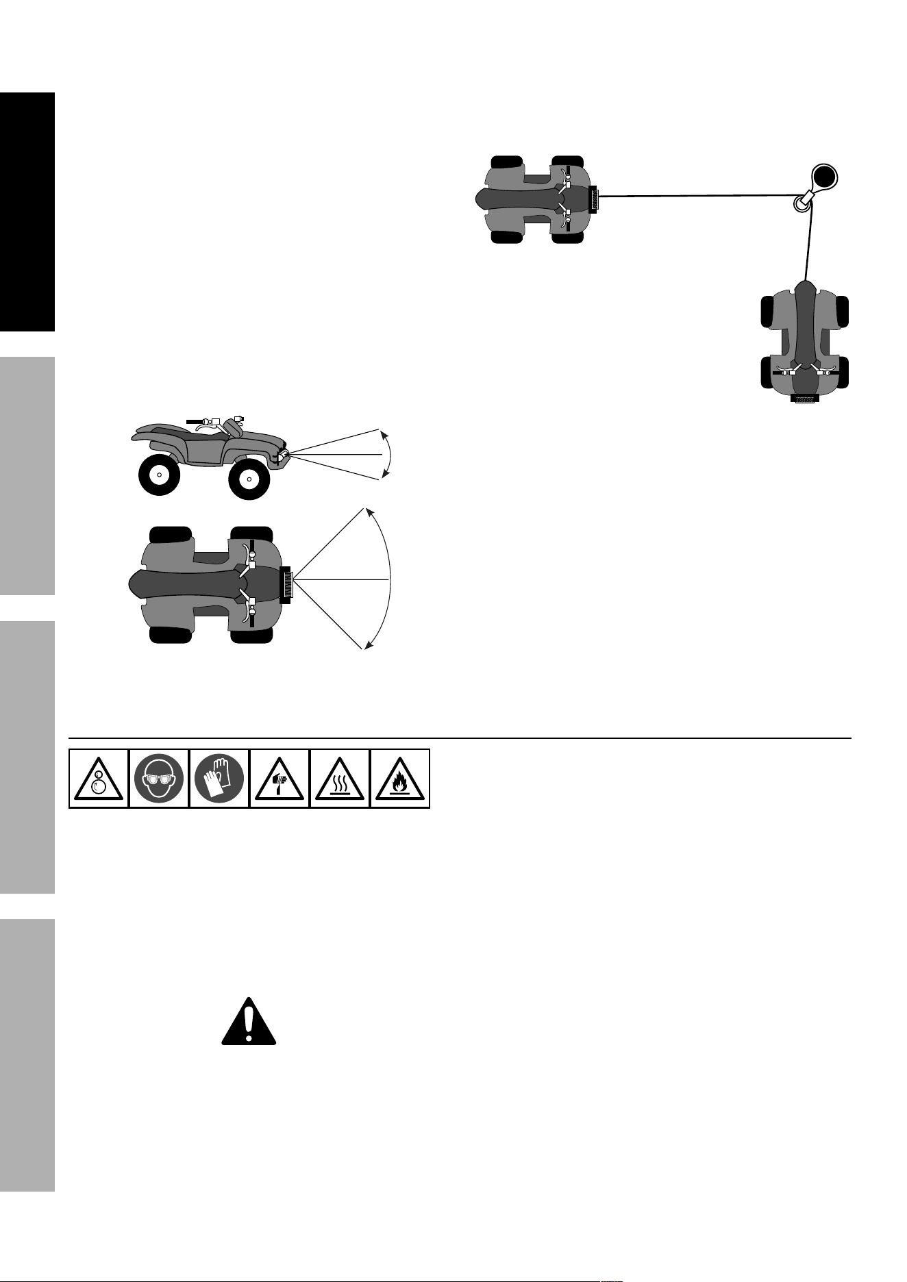
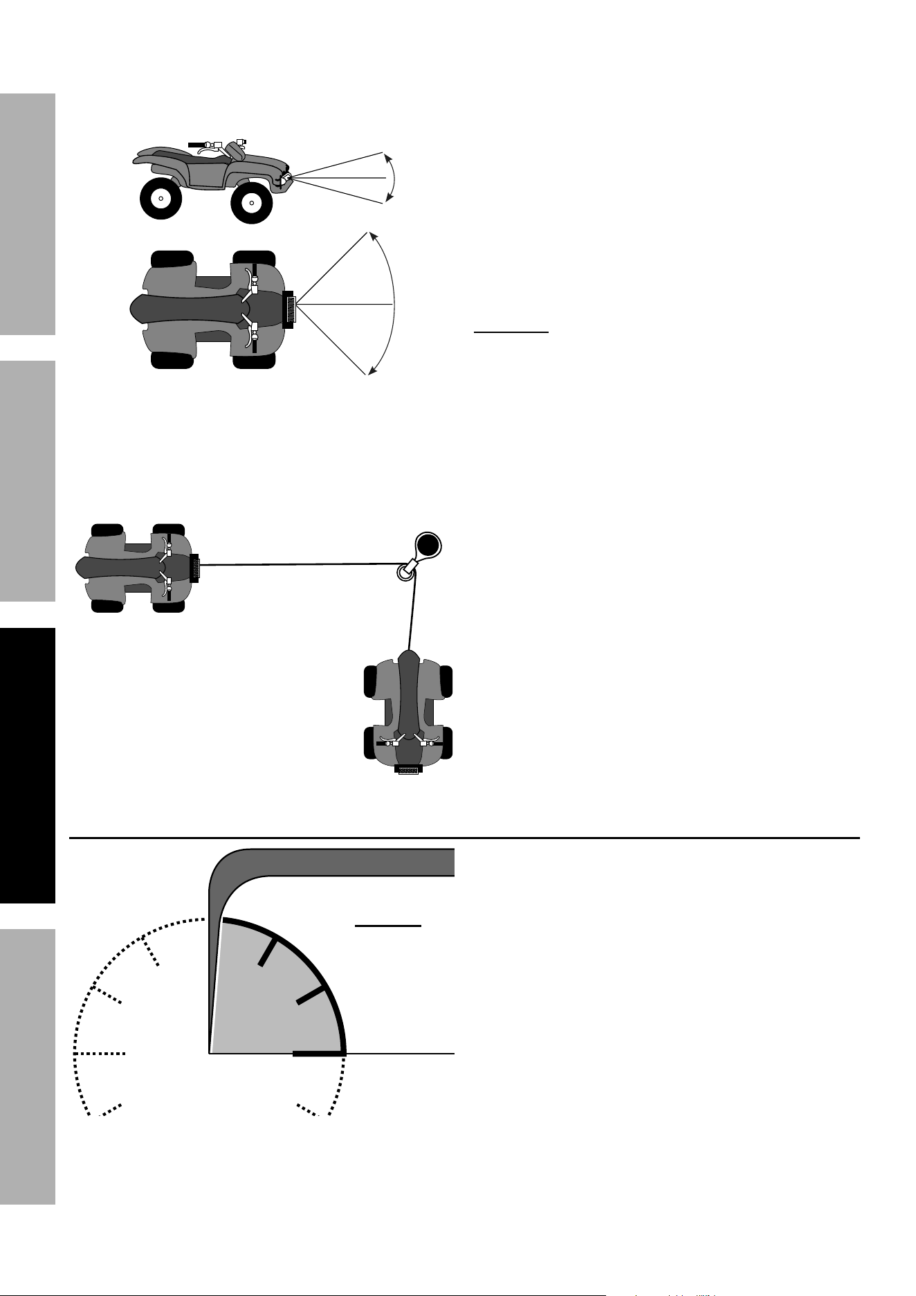
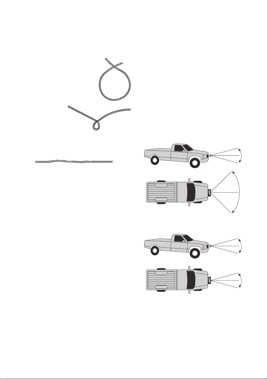
27. Do not operate the winch at extreme angles.
Do not exceed the angles shown in Figure B for
a roller fairlead. For a hawse fairlead, the angle
should be as close to straight as possible.
15°
15°
45°
45°
Figure B: Roller Fairlead Maximum Winching Angles
28. If the object to be pulled must be pulled at an
angle in relation to the winch, use a snatch block
(sold separately) and an anchor point directly
in front of the winch, as shown in Figure C,
to keep the synthetic rope pull straight.
Figure C: Snatch Block
29. Wear work gloves to protect from cuts from debris
when working with synthetic rope. Do not slide
synthetic rope through hands, even with gloves on.
30. Winch motor will be hot during
and after use. Keep clear.
31. Do not power the hook all the way
into the fairlead or winch.
32. People with pacemakers should consult their
physician(s) before use. Electromagnetic fields in
close proximity to heart pacemaker could cause
pacemaker interference or pacemaker failure.
Service Precautions
1. Wear ANSI-approved safety goggles and
heavy-duty leather work gloves during service.
2. Disconnect power to winch and allow it
to cool completely before service.
3. Use supplied power cords/synthetic rope or
cables listed in manual only. Do not use thinner/
longer cables or link multiple cables together.
4. Have the winch serviced by a qualified repair person
using only identical replacement parts. This will
ensure that the safety of the winch is maintained.
5. Maintain labels and nameplates on the winch.
These carry important safety information.
If unreadable or missing, contact
Harbor Freight Tools for a replacement.
SAVE THESE INSTRUCTIONS.
Page 7For technical questions, please call 1-888-866-5797.Item 57535
SAFETYOPERATIONMAINTENANCE SETUP
Installation and Setup
Read the ENTIRE IMPORTANT SAFETY INFORMATION section at the beginning of this manual
including all text under subheadings therein before set up or use of this product.
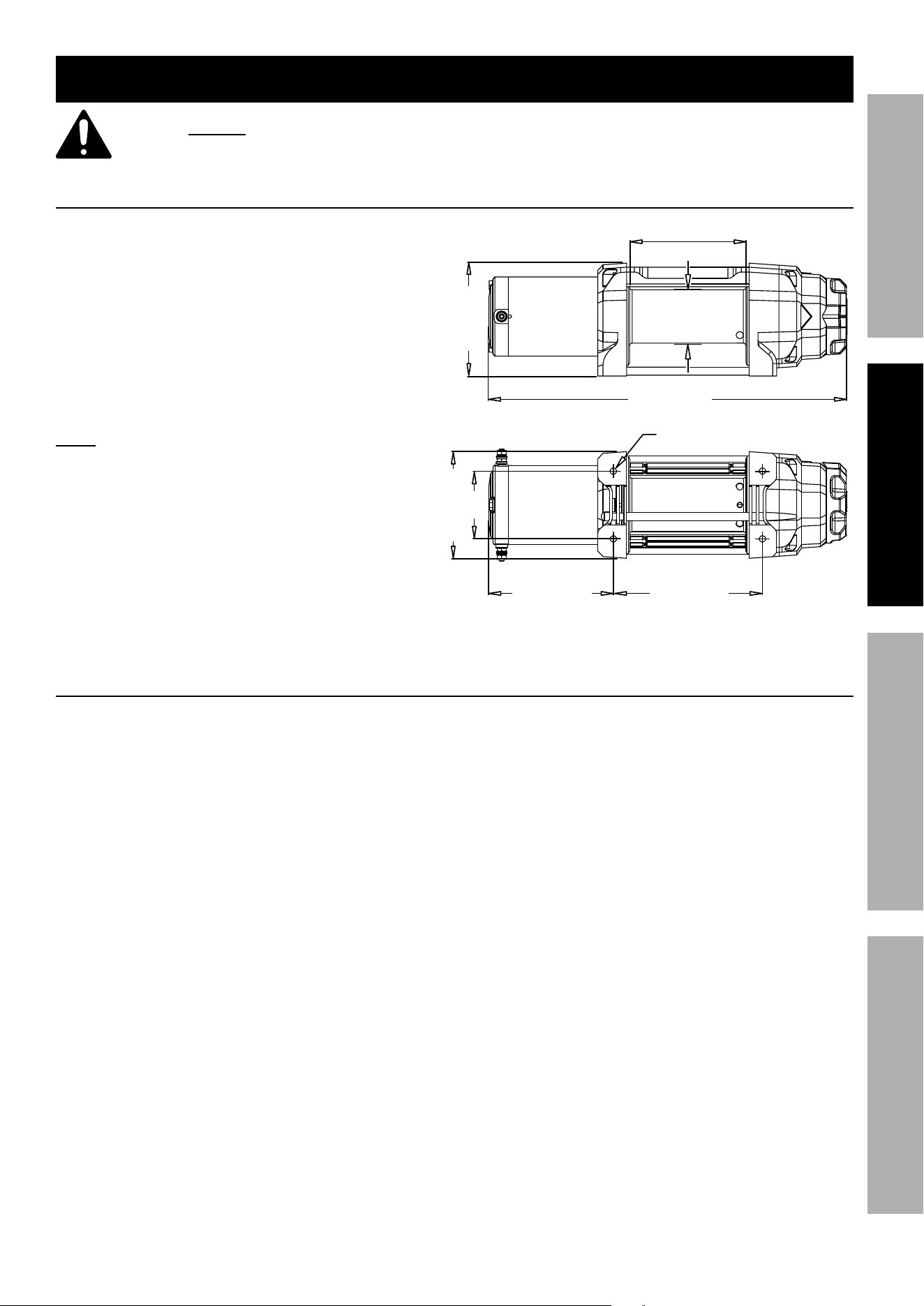
Mounting the Winch
1. The plate must be rated to at least
the Winch’s capacity.
2. Align the Winch perpendicular to center line of
the vehicle at the desired location, and mark the
locations of the Winch base holes. Compare the
dimensions of the marked holes to Figure D.
3. Before drilling, verify that the installation
surface has no hidden components or
structural pieces that will be damaged.
Note: This Winch can generate extreme forces.
Select a location that can withstand the rated
capacity without damage or weakening. Steel
reinforcement plates may be needed or a
certified welder may need to weld on additional
bracing depending on the mounting location.
4. Drill holes appropriate for the hardware
at the marked locations.
5. Install the Winch using hardware
described under Specifications.
4*Ø8.5 mm
(threaded)
4.72 in. / 120 mm
5.51 in. / 140 mm 6.6 in. / 167.8 mm
3 in. /
76 mm
2.36 in.
/ 60 mm
5.16 in. / 131 mm
5 in. / 127 mm
15.87 in. / 403 mm
Figure D: Winch Dimensions
Mounting Winch Components
1. Mount Solenoid box, Disconnect Switch, and
Socket Lead in proper locations so that:
a. Winch components are close enough to each
other to allow wires to be routed properly.
b. Vehicle component operation
is not interfered with.
c. Vehicle components are not damaged
by drilling or driving screws.
d. Winch components will not be damaged by
stresses caused by vehicle operation.
2. Mark the locations where the screw holes will be.
3. Verify that the installation surface has no
hidden components or structural pieces
that will be damaged before drilling.
4. Drill pilot holes for the mounting screws.
5. Secure in place with mounting screws.
Page 8 For technical questions, please call 1-888-866-5797. Item 57535
SAFETY OPERATION MAINTENANCESETUP
Wiring
TO PREVENT SERIOUS INJURY FROM EXPLOSION
DUE TO SPARKING AT THE BATTERY CONNECTION:
Disconnect the Battery Cables before making other wiring connections.
TO PREVENT SERIOUS INJURY FROM LEAKING BATTERY ACID:
Do not use a dirty, corroded or leaking battery.
Only use a 12V automotive (or equivalent) battery, in good condition.
1. Plan a route for the wiring from the point of
the vehicle where the Winch will be mounted,
or used, to the battery. This route must be
secure, out of the way of moving parts, road
debris, or any possibility of being damaged by
operation or maintenance of the vehicle. For
example, you may wish to route the wires under
the vehicle, attaching it to the frame using
suitable fasteners. Do not attach the wires to
the exhaust system, drive shaft, emergency
brake cable, fuel line, or any other components
which may create damage the wiring through
heat or motion, or create a fire hazard.
2. If you drill through the bumper or any part
of the body to route the wires, be sure
to install a rubber grommet in the hole to
prevent fraying of the wires at that point.
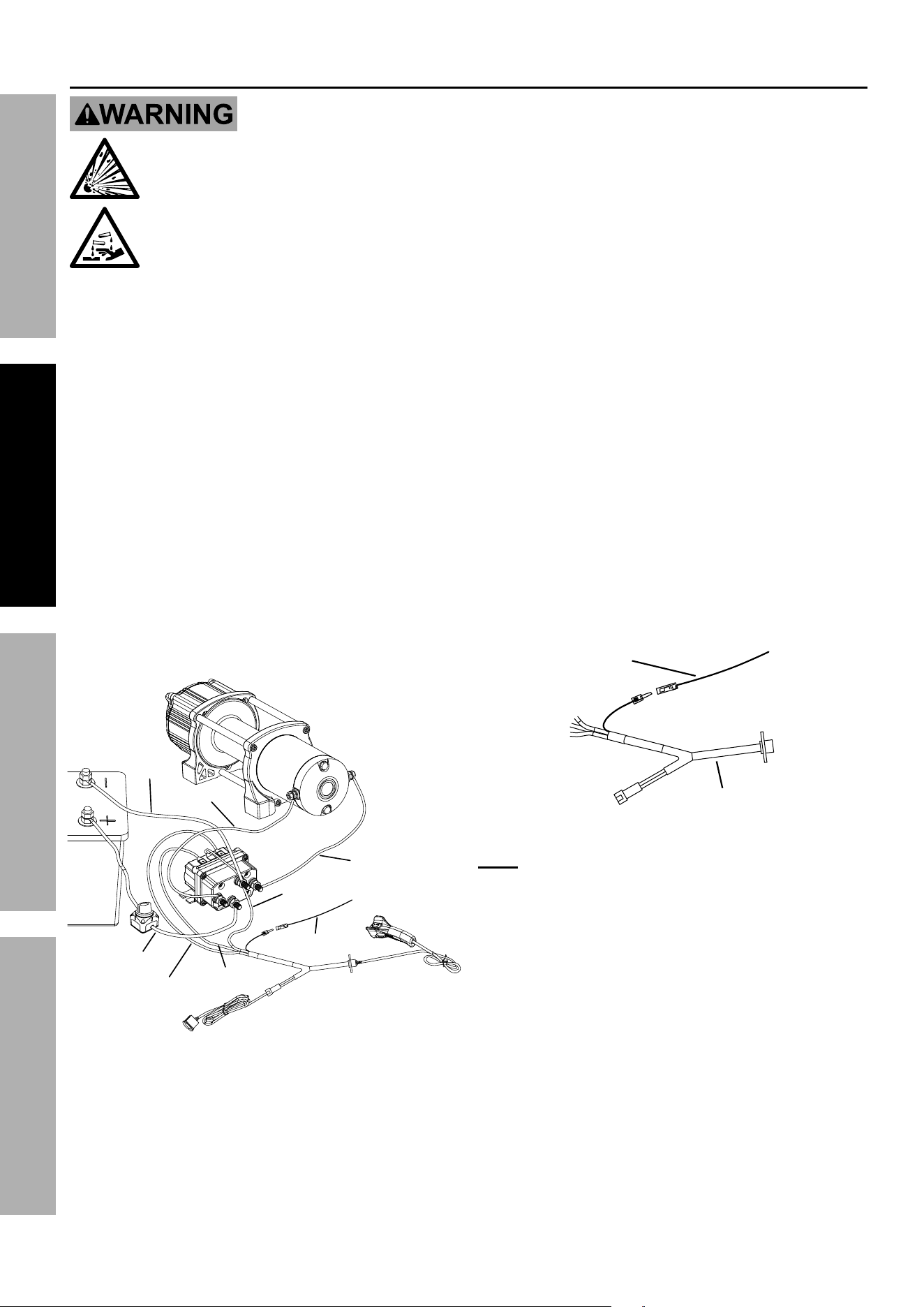
3. Route the Cables from the Solenoid to the battery
and from the Solenoid to the Winch, following the
precautions discussed earlier. Refer to Figure E.
Yellow
White
Green
Black
Red
Blue
Red
(
to ignition
)
Black
Figure E: Wiring Connections
4. Attach the wires from the solenoid to
the terminals on the Winch.
5. Attach the Disconnect Switch to the
Positive Terminal on the battery.
6. Attach the red Battery Cable to
the Disconnect Switch.
7. Attach the black Battery Cable directly to
the negative terminal of the battery.
8. Wire in the Remote Control, Dash Rocker
Switch, and Socket Lead according
to the diagrams on this page.
9. The cable leading from the Socket Lead
has a red ignition wire extending out from
its side. Connect this to an ignition circuit
(switched by the vehicle′s key) to help prevent
accidental starting. The Winch will not operate
if that wire is not properly connected.
a. Use a circuit tester to find a wire that energizes
when the vehicle′s key is turned to on, and
turns off when the key is turned to off.
b. That is an ignition controlled wire.
Connect the red Socket Lead ignition
wire to that wire. Refer to Figure F.
Red
(to ignition)
Socket Lead
Figure F: Wiring to vehicle′s keyed ignition
Note: If not attaching the Winch to a vehicle, attach
the ignition wire to the positive battery terminal.
IF THIS IS NOT DONE, THE WINCH
WILL NOT OPERATE.
10. After the unit is mounted and powered, turn
on the Disconnect Switch and operate the
Power In and Power Out button on the Remote
Control briefly to test Winch function and drum
rotation direction. If operation is reversed, the
Battery Cables may be connected backwards.
Correct any such issue before use.
11. Disconnect and turn off the Remote
Control when not in use.
12. Turn off the Disconnect Switch when the
Winch is not in use or when the vehicle
has returned to on-highway operation.

Page 9For technical questions, please call 1-888-866-5797.Item 57535
SAFETYOPERATIONMAINTENANCE SETUP
Disconnect Switch
WARNING! TO PREVENT SERIOUS INJURY: Off-highway driving subjects the vehicle and
wiring to much higher vibrations than on-highway driving which can cause a breakdown of wiring
insulation over time. Use the high current Disconnect Switch included with this Winch to turn
OFF the power to the Winch when it is not in use to help reduce the risk of a short circuit.
1. To use the Winch, use the Disconnect Switch
to turn the power to the Winch ON.
2. When the Winch is not in use, turn the
Disconnect Switch OFF to reduce the risk of
a short on the main power to the Winch.
Preparing the Synthetic Rope
The Synthetic Rope must be properly coiled under
tension to be able to support a load without damage.
1. Find a suitable location where the Rope can be
spooled onto the Winch while anchored to a solid
object. Approximately 70 feet will be required.
Alternately, a snatch block (sold separately) may
be used to reduce the distance to 35 feet.
2. Turn the Clutch Knob counterclockwise to the
Released (freespool) position. Turn the Knob
completely until it stops. Uncoil the Synthetic Rope
until 5 wraps remain on the drum. Turn the Clutch
Knob clockwise back to the Engaged position.
3. Slowly and carefully move the vehicle in
reverse to remove slack from the line.
4. Place the vehicle in neutral. Spool the Synthetic
Rope back into the Winch while gently applying
the brakes. If the ground is flat, shallow
mud or dirt, the brakes can be fully applied.
Pavement can generate much higher loads,
in which case only light braking is needed.
5. Use a second person to monitor the rope
spooling evenly onto the drum.
6. The last layer of Rope can be put on without tension.
Page 10 For technical questions, please call 1-888-866-5797. Item 57535
SAFETY OPERATION MAINTENANCESETUP
Operation
Read the ENTIRE IMPORTANT SAFETY INFORMATION section at the beginning of this manual
including all text under subheadings therein before set up or use of this product.
The instructions that follow are basic guidelines only and cannot cover all situations encountered
during use. The operator and assistants must carefully plan usage to prevent accidents.
Clutch Operation
CAUTION! Do not adjust the clutch unless there is no load on the Synthetic Rope.
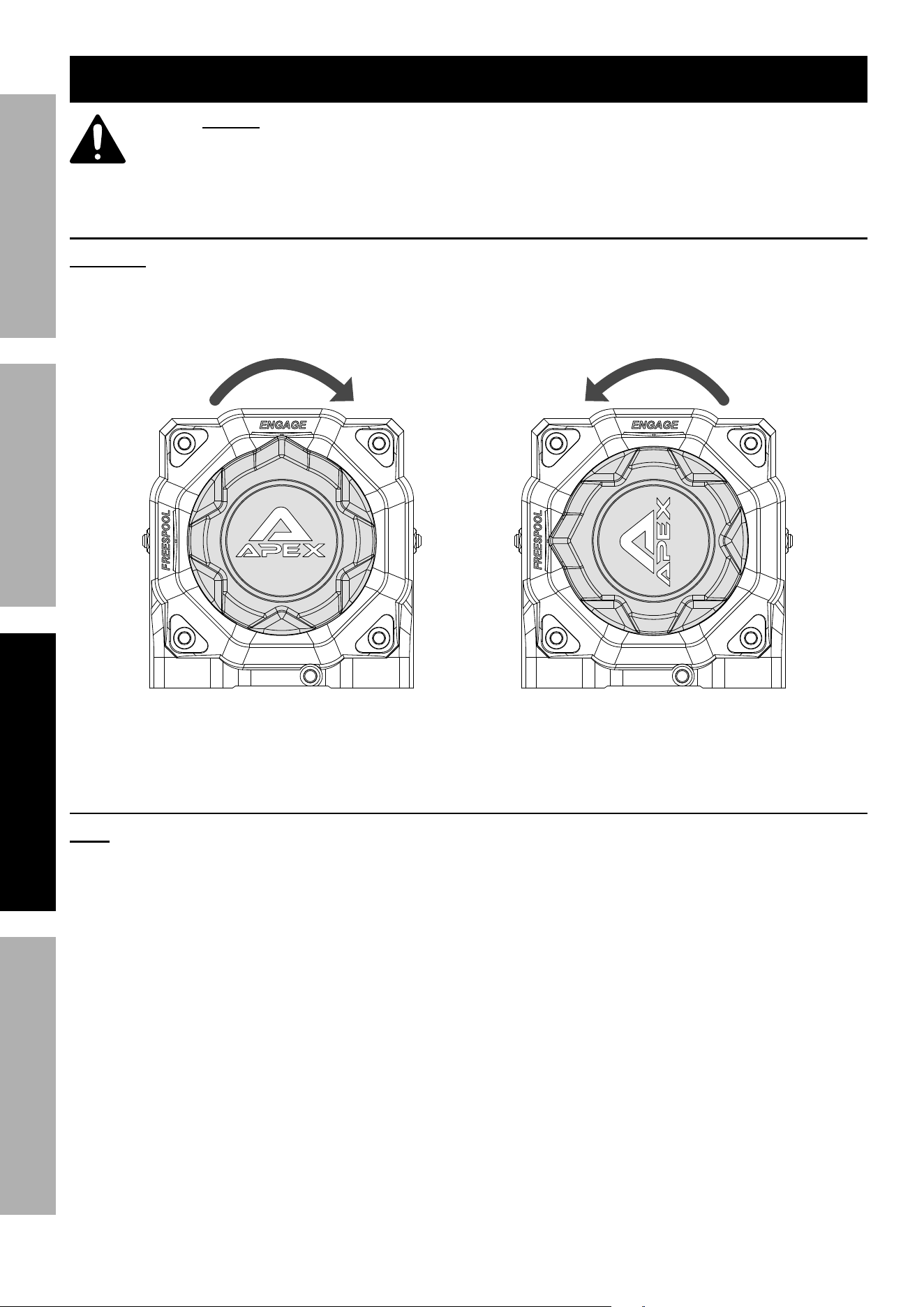
1. To engage the clutch, turn the Clutch
Knob clockwise completely until it
stops. Refer to Figure G.
2. To release the clutch (freespool), turn the
Clutch Knob counterclockwise completely
until it stops. Refer to Figure G.
Engage Release
(freespool)
Figure G: Clutch Operation
Basic Operation
Note: If a winch is to be used to pull a vehicle,
it should optimally be rated to a single line
pull at least twice the vehicle’s weight.
1. Examine the Synthetic Rope. Do not use the Winch
if the Synthetic Rope is frayed or has cut strands.
2. Fully charge the vehicle’s battery.
3. Check the Winch’s electrical connections.
All connections must be tight and clean.
4. Put the vehicle’s transmission in Neutral.
5. If the vehicle where the Winch is mounted
is not supposed to be moved, engage the
emergency brake and block the wheels
using wheel chocks (sold separately).
6. To pull out the Synthetic Rope, move the
Clutch Knob to the Released position – see
instructions for your Winch model under the
Clutch Operation section. Slide the loop of the
Hook Strap over the Hook, then pull on the Hook
Strap to pull out the Synthetic Rope.
CAUTION! Leave at least ten full turns
of Synthetic Rope on the drum.
Page 11For technical questions, please call 1-888-866-5797.Item 57535
SAFETYOPERATIONMAINTENANCE SETUP
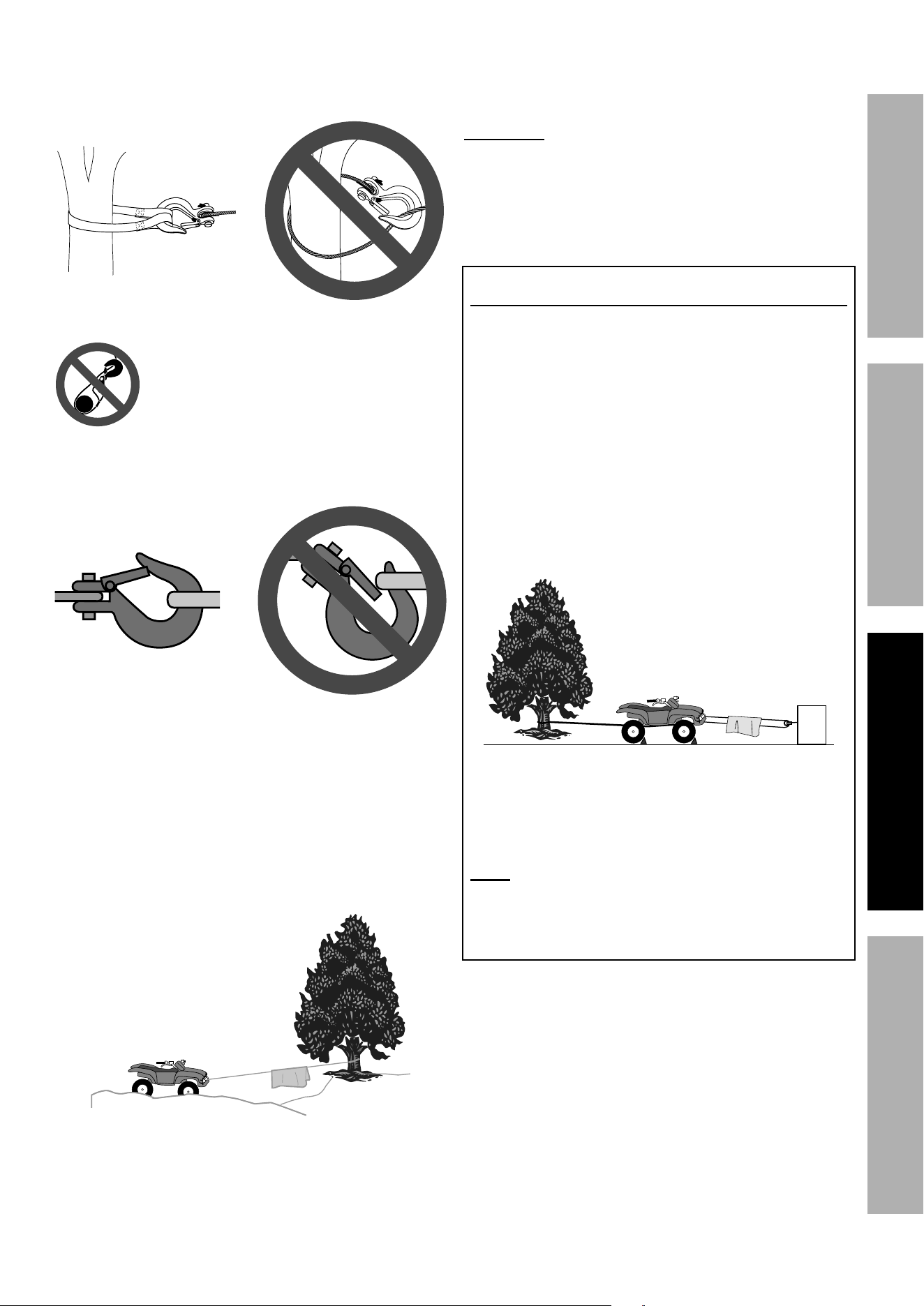
7. Hook onto the object using a pulling point,
tow strap, tree strap, or chain. See Figure H.
Shackle not shown between tree strap and hook.
Figure H: Using a strap anchor point
Do not wrap the Synthetic Rope around
the object and hook onto the
Rope itself. This can damage the object
being pulled and fray the Synthetic Rope.
8. Attachment point must be centered in
loop of hook and the hook’s safety clasp
must be fully closed. See Figure I.
Figure I: Correct and incorrect hook attachment
9. Do not use a Recovery Strap while winching.
They are designed to stretch and can
suddenly whip back towards the operator
during a winching operation.
10. Place a heavy blanket or winch damper (sold
separately) over the Synthetic Rope span 6
feet from the hook to help absorb the force
released if the Synthetic Rope breaks.
Figure A: Whiplash Dampening
Blanket or Winch Damper
11. Turn the Clutch Knob to the Engaged position.
See the instructions for your Winch model
under Clutch Operation on page 10.
WARNING! TO PREVENT SERIOUS INJURY: Do
not allow anyone to stand near the Synthetic Rope,
or in line with the Rope behind the Winch while it
is under power. If the Synthetic Rope should slip
or break, it can suddenly whip back towards the
Winch, causing a hazard for anyone in the area.
Stand well to the side while winching.
Double Line Rigging
a. A double line system should be used whenever
possible. It reduces the load on the winch,
allowing it to work longer with less heat buildup.
It reduces load on the winch in two ways:
• It utilizes the lower layers of Synthetic
Rope that have higher capacity, and
• It halves the load on the winch
through pulley action.
b. Connect the Synthetic Rope for a double line
system as shown in Figure J below. Use a
snatch block (sold separately) properly rated
for the load to be pulled and designed to be
operated with this winch’s Synthetic Rope.
Stationary
Winching Vehicle
(Chock tires,
set parking brake,
and leave in neutral)
Load
Damper
Figure J: Double Line setup
c. Loop the Synthetic Rope around the snatch block
and connect to another part of the vehicle’s chassis
or to a separate anchor point. Do not anchor
the Rope back to the winch or winch mount.
Note: If anchoring the winching vehicle,
only attach the anchor line to the front of the
vehicle. If the anchor line is attached to the
rear of the vehicle, the vehicle′s frame may be
damaged by the forces exerted by winching.
12. Operate the controls briefly to
ensure they work properly.
• The IN position should retract the winch cable.
• The OUT position should power out the cable.
If operation is reversed, the power cables
may be connected backwards.
Correct any such issue before use.
13. When it is safe to do so, use the power switch on the
Remote Control to retract the Synthetic Rope, and
winch the item as desired. Do not power the Hook
all the way into the Fairlead to prevent damage.
Page 12 For technical questions, please call 1-888-866-5797. Item 57535
SAFETY OPERATION MAINTENANCESETUP
14. Do not operate the Winch at extreme angles.
Do not exceed the angles shown in Figure B for
a roller fairlead. For a hawse fairlead, the angle
should be as close to straight as possible.
15°
15°
45°
45°
Figure B: Roller Fairlead Maximum Winching Angles
15. If the object to be pulled must be pulled at an
angle in relation to the Winch, use a snatch block
(sold separately) and an anchor point directly
in front of the Winch, as shown in Figure C,
to keep the Synthetic Rope pull straight.
Figure C: Snatch Block
16. WARNING! TO PREVENT SERIOUS
INJURY: Stop the Winch and release tension
on the Synthetic Rope before moving the
blanket or winch damper placed on it.
17. Do not continue use of the Winch until
the battery is completely run down.
18. When possible, keep the engine running while using
this Winch, to continually recharge the battery and
prevent the battery from being drained so much that
the vehicle cannot start. However, exercise extreme
caution when working around a running vehicle
and ONLY operate a vehicle in an outdoor area.
CAUTION! Do not use the Winch in a
constant duty application, it is designed for
INTERMITTENT USE ONLY. Keep the duration
of the pulling job as short as possible. If the
motor becomes very hot to the touch, stop and
let it cool down for several minutes. Do not pull
for more than one minute at or near the rated
load. Do not maintain power to the Winch if
the motor stalls. Double Line Rigging will help
prevent overloading and should be used whenever
practical. See Double Line Rigging on page 11.
19. When finished pulling the load, reverse the direction
of the Winch just enough to release tension on
the Synthetic Rope so that you can unfasten
the Hook from the load and reel in the Rope.
20. Disconnect the Remote Control
(if equipped) after use.
Duty Cycle (Duration of Use)
at least
14 minutes,
15 seconds
of rest
45 seconds winching
Avoid damage to the Winch by not winching
for more than the prescribed duty cycle time.
The Duty Cycle defines the amount of time, within
a 15 minute period, during which a Winch can
operate at its maximum capacity without overheating.
For example, this Winch with a 5% duty cycle at its
maximum load must be allowed to rest for at least
14 minutes, 15 seconds after every 45 seconds of
continuous operation. Failure to carefully observe
duty cycle limitations can easily over-stress a
Winch contributing to premature Winch failure.

Page 13For technical questions, please call 1-888-866-5797.Item 57535
SAFETYOPERATIONMAINTENANCE SETUP
Maintenance and Servicing
Procedures not specifically explained in this manual must
be performed only by a qualified technician.
TO PREVENT SERIOUS INJURY FROM ACCIDENTAL OPERATION:
Disconnect the Battery Cables before performing any
inspection, maintenance, or cleaning procedures.
TO PREVENT SERIOUS INJURY FROM WINCH FAILURE:
Do not use damaged equipment. If abnormal noise or vibration
occurs, have the problem corrected before further use.
Cleaning, Maintenance, and Lubrication
1. BEFORE EACH USE, inspect the general
condition of the Winch. Check for:
• loose hardware
• misalignment or binding of moving parts
• cracked or broken parts
• damaged electrical wiring
• corroded or loose terminals
• any other condition that may
affect its safe operation.
Examine the Synthetic Rope. Do not use the
Winch if the Rope is frayed or has cut strands.
2. AFTER USE, wipe external surfaces
of the Winch with clean cloth.
3. The Winch’s internal mechanism is permanently
lubricated. Do not open the housing. However,
if the Winch is submerged, it should be opened,
dried, and re-lubricated by a qualified technician
as soon as possible to prevent corrosion.
Synthetic Rope Replacement
1. Turn the Clutch Knob counterclockwise to
the Released (freespool) position. Turn the
Knob completely until it stops. Refer to
Clutch Operation on page 10.
2. Extend the Synthetic Rope to its full
length, noting how the existing Rope is
connected to the inside of the drum.
3. Remove old Synthetic Rope and
attach new assembly.
CAUTION! Do not replace with inferior synthetic
rope. Only use a synthetic rope rated to the same
rating cited on the specification chart or better.
4. Retract Synthetic Rope onto Rope drum.
Refer to instructions for tensioning the Synthetic
Rope under Disconnect Switch on page 9.
5. Test Winch for proper operation.

Page 14 For technical questions, please call 1-888-866-5797. Item 57535
SAFETY OPERATION MAINTENANCESETUP
Troubleshooting
Problem Possible Causes Likely Solutions
Motor
overheats.
1. Incorrect power cords.
2. Winch running time too long.
3. Insufficient current or voltage.
4. Loose motor connections.
1. Use only supplied power cords.
2. Allow Winch to cool down periodically.
3. Fully charge battery. Run Winch
with vehicle motor running.
4. Check and tighten motor connections to Solenoid.
Motor does
not turn on.
1. Remote Control not
connected properly.
2. Loose battery cable connections.
3. Vehicle battery needs charging.
4. Solenoid malfunctioning.
5. Defective Remote Control.
6. Winch Disconnect Switch turned OFF.
7. Defective motor.
8. Water has entered motor.
9. Internal damage or wear.
1. Insert Remote Control cord all
the way into connector.
2. Tighten nuts on all cable connections.
3. Fully charge battery.
4. Tap Solenoid to loosen contacts.
Apply 12 volts to coil terminals directly.
A clicking indicates proper activation.
5. Replace Remote Contro.
6. Turn ON Winch Disconnect Switch.
7. Check for voltage at armature port with Switch
pressed. If voltage is present, replace motor.
8. Allow to drain and dry. Run in short bursts
without load until completely dry.
9. Have technician service Winch.
Motor runs
but drum does
not turn.
Clutch not engaged. Turn the Clutch Knob to the Engaged position.
If problem persists, a qualified technician
needs to check and repair.
Motor runs
slowly or without
normal power.
1. Insufficient current or voltage.
2. Loose or corroded battery
cable connections.
3. Incorrect power cords.
1. Battery weak, recharge.
Run Winch with vehicle motor running.
2. Clean, tighten, or replace.
3. Use only supplied power cords.
Motor runs in
one direction
only.
1. Defective or stuck Solenoid.
2. Defective Remote Control.
1. Tap Solenoid to loosen contacts.
Repair or replace Solenoid.
2. Replace Remote Control.
Follow all safety precautions whenever diagnosing or servicing
the tool. Disconnect power supply before service.
PLEASE READ THE FOLLOWING CAREFULLY
THE MANUFACTURER AND/OR DISTRIBUTOR HAS PROVIDED THE PARTS LIST AND ASSEMBLY DIAGRAM
IN THIS MANUAL AS A REFERENCE TOOL ONLY. NEITHER THE MANUFACTURER OR DISTRIBUTOR
MAKES ANY REPRESENTATION OR WARRANTY OF ANY KIND TO THE BUYER THAT HE OR SHE IS
QUALIFIED TO MAKE ANY REPAIRS TO THE PRODUCT, OR THAT HE OR SHE IS QUALIFIED TO REPLACE
ANY PARTS OF THE PRODUCT. IN FACT, THE MANUFACTURER AND/OR DISTRIBUTOR EXPRESSLY
STATES THAT ALL REPAIRS AND PARTS REPLACEMENTS SHOULD BE UNDERTAKEN BY CERTIFIED AND
LICENSED TECHNICIANS, AND NOT BY THE BUYER. THE BUYER ASSUMES ALL RISK AND LIABILITY
ARISING OUT OF HIS OR HER REPAIRS TO THE ORIGINAL PRODUCT OR REPLACEMENT PARTS
THERETO, OR ARISING OUT OF HIS OR HER INSTALLATION OF REPLACEMENT PARTS THERETO.
Record Product’s Serial Number Here:
Note: If product has no serial number, record month and year of purchase instead.
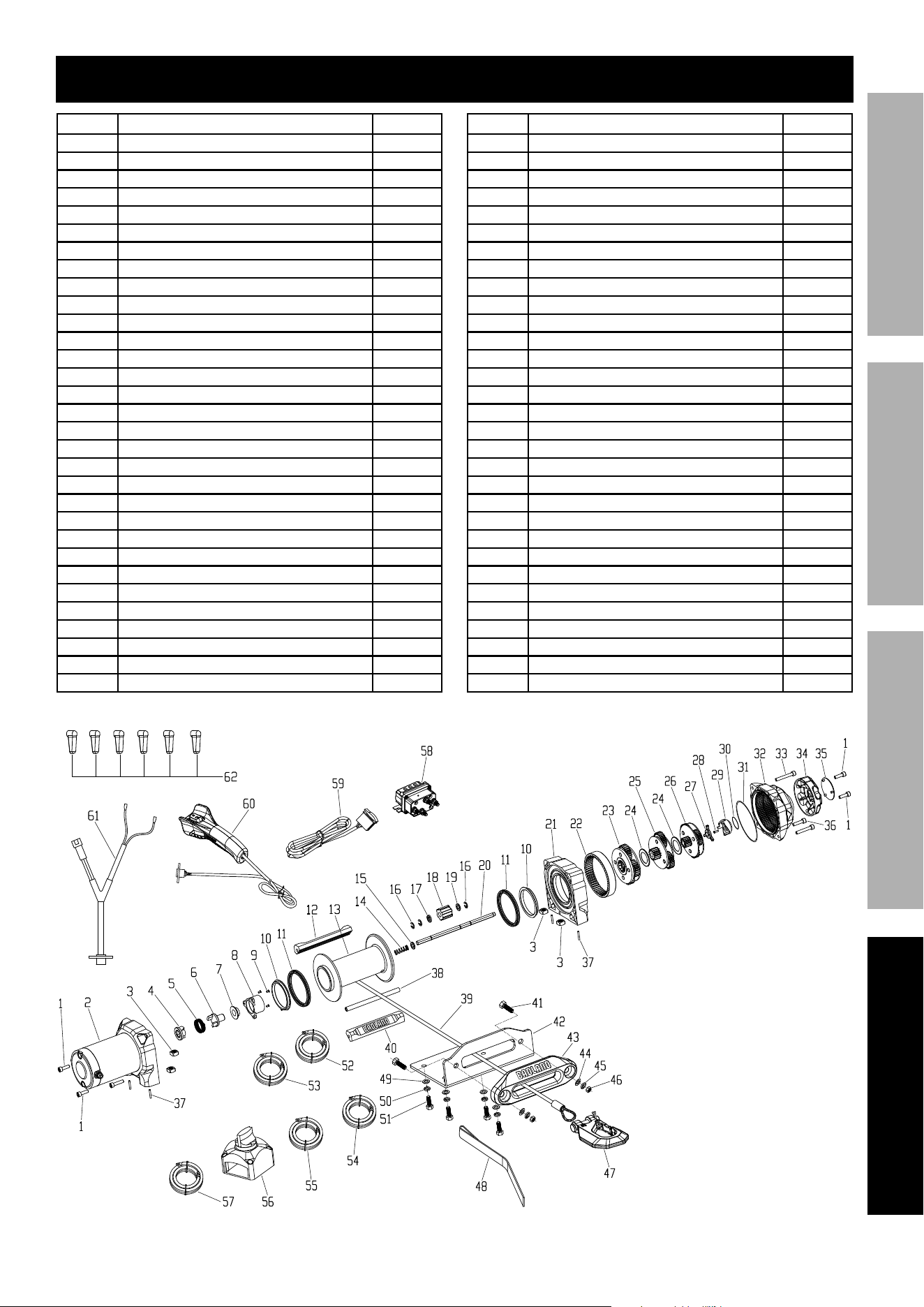
Note: Some parts are listed and shown for illustration purposes only, and are not available
individually as replacement parts. Specify UPC 193175417060 when ordering parts.
Page 15For technical questions, please call 1-888-866-5797.Item 57535
SAFETYOPERATIONMAINTENANCE SETUP
Parts List and Assembly Diagram
Part Description Qty
1 Hex Socket Screw M6 x 18 4
2 Motor Assembly 1
3 Nut M8 4
4 Brake Base 1
5 Brake Spring 1
6 Brake Fork 1
7 Brake Fork Locating Ring 1
8 Brake Housing 1
9 Screw M4 x 8 3
10 Sliding Bearing 2
11 Seal 2
12 Aluminum Tie Bar (no logo) 1
13 Drum 1
14 Spring 1
15 Washer 1
16 Clip 3
17 Hex Plate 1
18 Spline 1
19 Copper Plate 1
20 Drive Shaft 1
21 Gear Box Base 1
22 Ring Gear 1
23 Plantary Gear 3 1
24 Spacer 2
25 Plantary Gear 2 1
26 Plantary Gear 1 1
27 Fork Pin 1
28 Screw M4 x 8 1
29 Clutch Knob Base 1
30 O-Ring 1
31 O-Ring 1
Part Description Qty
32 Gear Box 1
33 Hex Socket Screw M6 x 50 2
34 Clutch Knob 1
35 Badge 1
36 Hex Socket Screw M6 x 25 2
37 Pin 2.5 x 14 4
38 Tie Bar 1
39 Synthetic Rope 1
40 Aluminum Tie Bar (with logo) 1
41 Screw 2
42 Mounting Plate 1
43 Aluminum Hawse Fairlead 1
44 Flat Washer 2
45 Lock Washer 2
46 Nut 2
47 Hook 1
48 Hand Strap 1
49 Flat Washer 1
50 Lock Washer 4
51 Screw 4
52 Motor Lead – Red 1
53 Solenoid Lead – Blue 1
54 Solenoid Lead – Yellow 1
55 Battery Lead – Black 1
56 Disconnect Switch 1
57 Battery Lead – Red 1
58 Solenoid 1
59 Dash Mounted Rocker Switch 1
60 Remote Control 1
61 Socket Lead 1
62 Rubber Boot 6

26541 Agoura Road • Calabasas, CA 91302 • 1-888-866-5797
Limited 90 Day Warranty
Harbor Freight Tools Co. makes every effort to assure that its products meet high quality and durability standards,
and warrants to the original purchaser that this product is free from defects in materials and workmanship for the
period of 90 days from the date of purchase. This warranty does not apply to damage due directly or indirectly,
to misuse, abuse, negligence or accidents, repairs or alterations outside our facilities, criminal activity, improper
installation, normal wear and tear, or to lack of maintenance. We shall in no event be liable for death, injuries
to persons or property, or for incidental, contingent, special or consequential damages arising from the use of
our product. Some states do not allow the exclusion or limitation of incidental or consequential damages, so the
above limitation of exclusion may not apply to you. THIS WARRANTY IS EXPRESSLY IN LIEU OF ALL OTHER
WARRANTIES, EXPRESS OR IMPLIED, INCLUDING THE WARRANTIES OF MERCHANTABILITY AND FITNESS.
To take advantage of this warranty, the product or part must be returned to us with transportation charges
prepaid. Proof of purchase date and an explanation of the complaint must accompany the merchandise.
If our inspection verifies the defect, we will either repair or replace the product at our election or we may
elect to refund the purchase price if we cannot readily and quickly provide you with a replacement. We will
return repaired products at our expense, but if we determine there is no defect, or that the defect resulted
from causes not within the scope of our warranty, then you must bear the cost of returning the product.
This warranty gives you specific legal rights and you may also have other rights which vary from state to state.

WWW.HARBORFREIGHT.COM
Copyright
©
2019 by Harbor Freight Tools
®
. All rights reserved. No portion of this guide or any artwork contained herein may be reproduced in
any shape or form without the express written consent of Harbor Freight Tools. Diagrams within this guide may not be drawn proportionally.
GUIDE TO WINCHING
19e

Page 2 For technical questions, please call 1-888-866-5797. Winching
Guide
Table of Contents
Warning Symbols .......................................... 3
Important Safety Information ......................... 4
Basic Winching Tips ...................................... 7
Before You Go ............................................... 7
Estimating Load ............................................. 8
Winch Basics ................................................ 10
.............. 14
............ 16
Double Line Winching................................... 18
Read the ENTIRE IMPORTANT SAFETY INFORMATION section beginning
on page 4 of this guide including all text under subheadings therein before
use of this product. The instructions that follow are basic guidelines
only and cannot cover all situations encountered during use. The
operator and assistants must carefully plan usage to prevent accidents.
Page 3For technical questions, please call 1-888-866-5797.Winching
Guide
WARNING SYMBOLS AND DEFINITIONS
This is the safety alert symbol. It is used to alert you to potential
personal injury hazards. Obey all safety messages that follow
this symbol to avoid possible injury or death.
Indicates a hazardous situation which, if not avoided,
will result in death or serious injury.
Indicates a hazardous situation which, if not avoided,
could result in death or serious injury.
Indicates a hazardous situation which, if not avoided,
could result in minor or moderate injury.
Addresses practices not related to personal injury.
Symbol Property or Statement
Wear heavy-duty, cut- and
abrasion-resistant leather gloves.
Wear ANSI-approved safety glasses.
Cut or sever hazard.
Roller entanglement hazard.
Hot surface burn hazard.
Fire hazard.
Caustic chemical (acid) hazard.
Explosion hazard.
Do not loop the wire or synthetic rope
around object and hook onto itself.
Do not place finger(s) through hook.
Fingers may be caught and get
pulled into fairlead or drum.
Pull hook using strap only.
Symbol Property or Statement
Do not use winch in overwind
orientation. (Rope enters/
exits at the top.)
Use winch only in
underwind orientation.
(Rope enters/exits at the bottom.)
VDC
Volts Direct Current
A
Amperes
CCA
HP
Horsepower
fpm
Feet Per Minute
mpm
Meters Per Minute
RPM
Revolutions Per Minute
IP
International Protection rating
Classifies the degrees of protection provided
against the intrusion of solid objects,
dust, accidental contact, and water.
G8
Grade 8
A fastener strength rating.
Page 4 For technical questions, please call 1-888-866-5797. Winching
Guide
IMPORTANT SAFETY INFORMATION
WARNING! Read all instructions. Failure to follow all instructions listed on
pages 4 to 6 may result in fire, serious injury and/or DEATH.
The warnings and precautions discussed in this manual cannot cover all
possible conditions and situations that may occur. It must be understood
by the operator that common sense and caution are factors which cannot
be built into this product, but must be supplied by the operator.
Operation Precautions
1. Do not exceed load capacity. Be
aware of dynamic loading! Sudden
load movement may briefly create
excess load causing product failure.
2. Do not maintain power to the Winch
if the motor stalls. Verify load is within
rated capacity for the wire or synthetic
fully charged. Use double line rigging
whenever possible. Refer to Double
Line Winching on page 18.
3. Wear ANSI-approved safety
goggles and heavy-duty leather
4. Do not disengage clutch under load.
Engage clutch before starting.
5. Keep clear of fairlead when operating.
Do not try to guide rope.
6. Do not place finger(s) through hook.
Fingers may be caught and get pulled
into fairlead or drum. Use included
7. Stay out of the direct line that the rope
it will “whiplash” along this line.
8. Do not use for lifting or moving people.
9. Use a spotter to assist you in assuring
that it is safe to operate the Winch.
way of the vehicle and the rope
before activating the Winch.
10. Do not use vehicle to pull on the
rope and “assist” the Winch.
11.
to help absorb the force released if
Refer to Figure A.
Figure A: Whiplash Dampening
Blanket or Winch Damper
12. Use as intended only. Do not lift items
vertically or use for aircraft purposes.
13. Prevent entanglement. Do not wear
loose clothing or jewelry, as they can be
is recommended. Wear restrictive hair
covering to contain long hair.
14. Disconnect remote control and turn
near the rope, drum, fairlead or load,
to prevent accidental starting.
15. Inspect before every use; do not use
if damaged or parts loose. Examine
frayed or cut synthetic rope, and any
other conditions that may affect the safe
operation of the Winch. Do not use the
Winch even if minor damage appears.
Page 5For technical questions, please call 1-888-866-5797.Winching
Guide
16.
wire rope can fail suddenly and must
not be used. Keep wire rope straight
a.
about to form. At this point
the winch should be
stopped and the wire rope
should be straightened out
b. This wire
It is too late to
reverse the
damage at this
point, the wire rope must be discarded.
It is permanently damaged and must not
be used.
c.
been straightened out. Even though it
has been pulled straight, some wires
in the wire rope are stretched, and
load and can fail suddenly before the
rope reaches its capacity. This wire rope
must be discarded and not be used.
rope, even after it is straightened
suddenly and must not be used.
17. Keep children and bystanders
away while operating. Distractions
can cause you to lose control.
18. Stay alert, watch what you are doing
and use common sense when operating.
Do not use a winch while you are
tired or under the influence of drugs,
alcohol or medication. A moment of
inattention while operating winches
may result in serious personal injury.
19. Do not overreach. Keep proper
footing and balance at all times.
This enables better control of the
Winch in unexpected situations.
20.
tow strap or chain. Do not wrap the rope
rope itself. This can cause damage to the
21. Do not use a Recovery Strap while
winching. They are designed to stretch
operator during a winching operation.
22. Do not operate the Winch at extreme
angles. Do not exceed the angles
shown in Figure B for a roller fairlead
and Figure C for a hawse fairlead.
45°
45°
15°
15°
Figure B: Roller Fairlead
Maximum Winching Angles
15°
15°
15°
15°
Figure C: Hawse Fairlead
Maximum Winching Angles
Page 6 For technical questions, please call 1-888-866-5797. Winching
Guide
23. If the object to be pulled must be pulled
at an angle in relation to the Winch,
and an anchor point directly in front
of the Winch, as shown in Figure D,
Figure D: Snatch Block
24. Wrap rope under tension before use.
Otherwise, rope may bind during operation.
25.
winching. Do not step over rope.
Do not push sideways against rope
under tension; rope might break under
this load and recoil back, striking the
person pushing against it or a bystander.
26. If rope begins to get entangled, stop Winch
immediately and release rope using switch.
27.
transmission in neutral. Winching with
to handle that type of load.
28.
when handling a wire rope. Do not
slide a wire or synthetic rope through
hands, even with gloves on.
29. Winch motor will be hot during
and after use. Keep clear.
30.
into the fairlead or Winch.
31. To prevent accidental starting, unplug
winch controls and any RF receivers
immediately after extending or retracting.
This is especially important before rigging,
installing, free spooling, or servicing.
32.
Electromagnetic fields in close proximity to
Service Precautions
1. Wear ANSI-approved safety
goggles and heavy-duty leather
2. Disconnect power to Winch and allow
it to cool completely before service.
3. Use supplied power cords, rope or
cables listed in manual only. Do
not use thinner/longer cables or
4. Have the Winch serviced by a qualified
repair person using only identical
replacement parts. This will ensure that
the safety of the Winch is maintained.
5. Maintain labels and nameplates
on the Winch. These carry important
safety information. If unreadable
or missing, contact Harbor Freight
Tools for a replacement.
SAVE THESE INSTRUCTIONS.
Page 7For technical questions, please call 1-888-866-5797.Winching
Guide
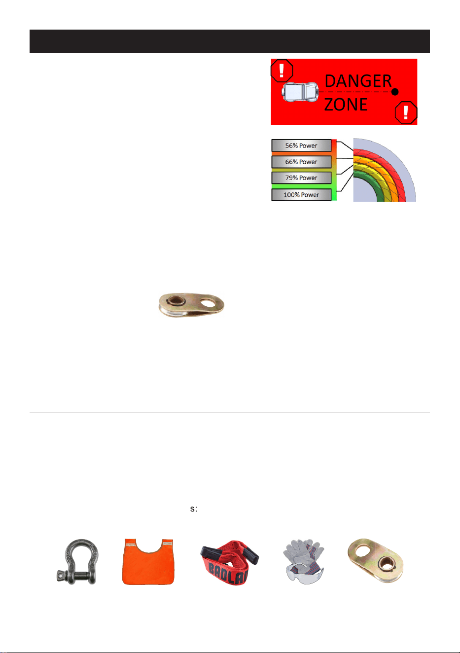
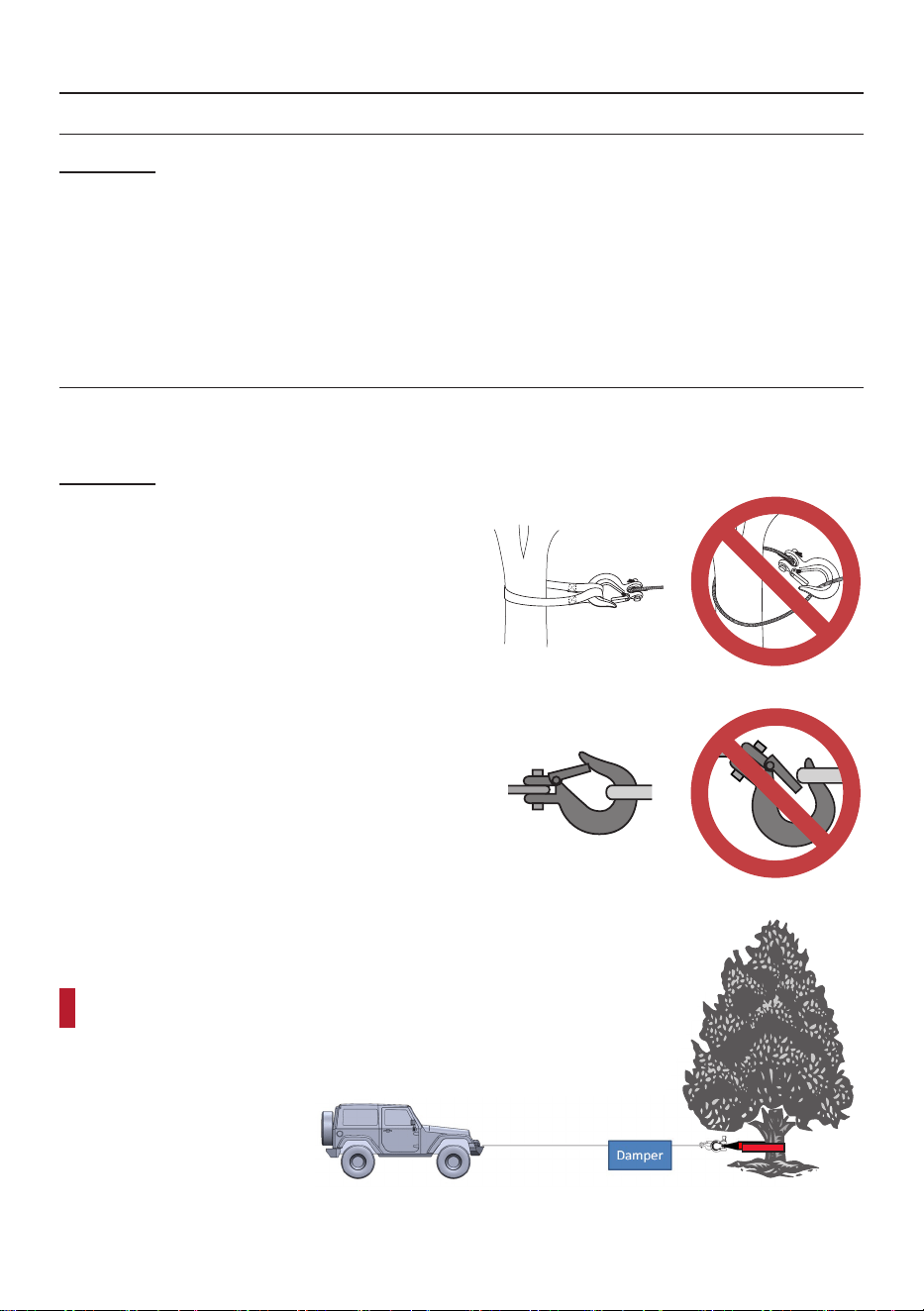
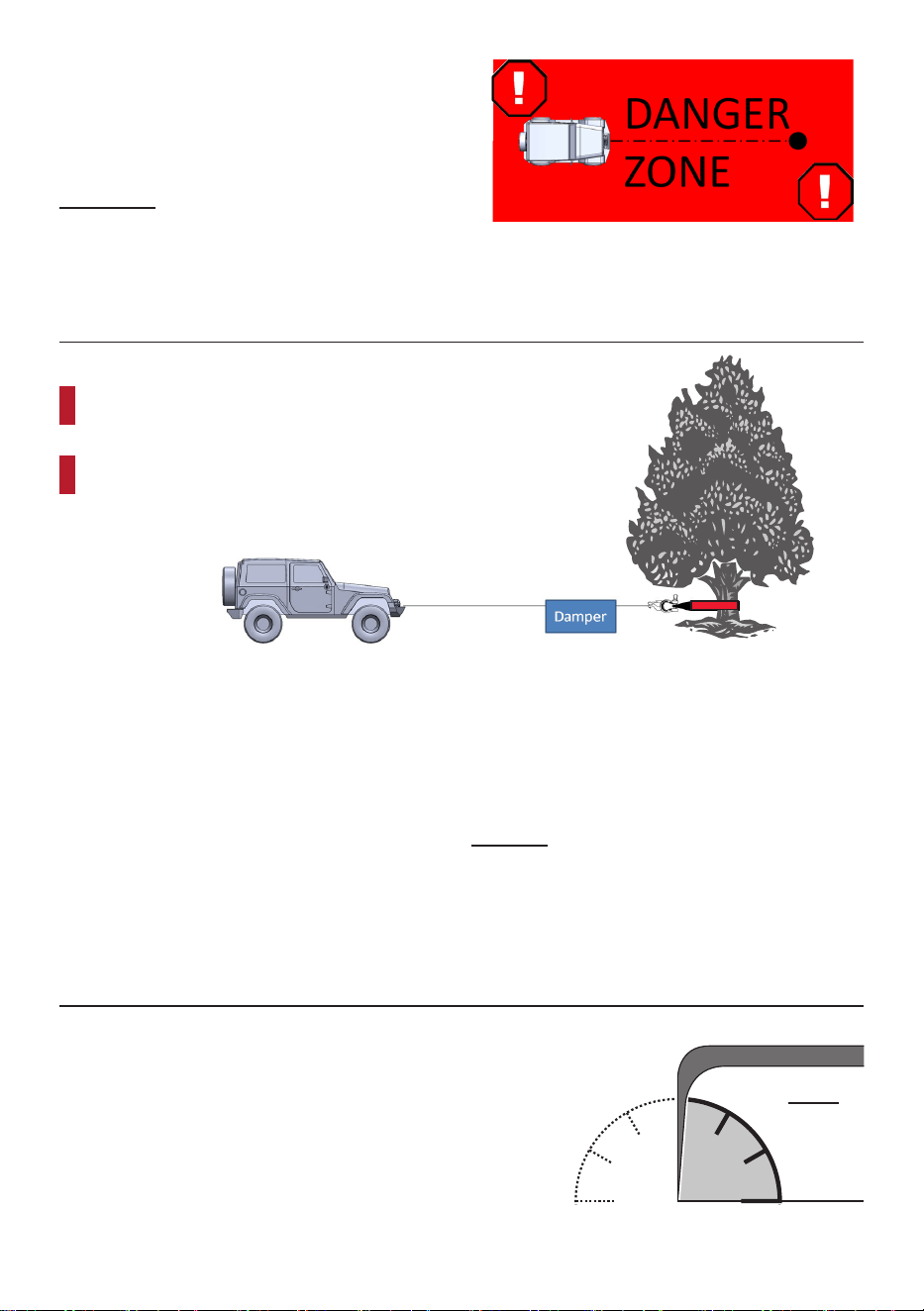
Basic Winching Tips
• ESTABLISH A DANGER ZONE:
no people enter during the winching operation or
when the line is under tension.
• FIRST LAYER WINCHING:
Winch with the most rope out possible to
utilize the maximum power of the winch and
prevent overloading and overheating.
• WINCH RECOVERIES ARE SLOW:
precautions. The loads that the
winch can generate are extreme.
• USE A SNATCH BLOCK:
When in doubt of the
recovery load or if the two
each other, use a snatch
• KEEP VEHICLE RUNNING:
The winch will place an enormous amount
of strain on the vehicle electrical system.
Keeping the engine at 2000 RPM can
provide some help from the alternator.
• KEEP THE VEHICLE IN NEUTRAL:
hold the loads that the winch can apply.
carefully steer vehicle to avoid obstacles
• KEEP THE LINE STRAIGHT:
Winch with the rope as straight as possible to the
Before You Go
1.
to the winch for abrasion and heat
damage. Replace if worn or damaged.
2. The winch is an intermittently used
for proper operation in three mode
•••
2. Inspect the rope for signs of abrasion
damage. Replace if damaged. See Rope
Inspection on page 13 for more detail.
3. Ensure you have basic rigging
safety glasses, and gloves. A snatch
Damper Tree Strap Safety Gear
Page 8 For technical questions, please call 1-888-866-5797. Winching
Guide
Estimating Load
learn. It allows you to properly setup rigging for a successful recovery the first time
and reduces the chance of equipment damage and danger to bystanders.
Resistance Types
• Grade Resistance: The resistance
of pulling a vehicle up a slope.
• Mire Resistance: The resistance
of pulling a vehicle from soft terrain,
such as mud, sand or snow.
• Tackle Resistance: The added resistance
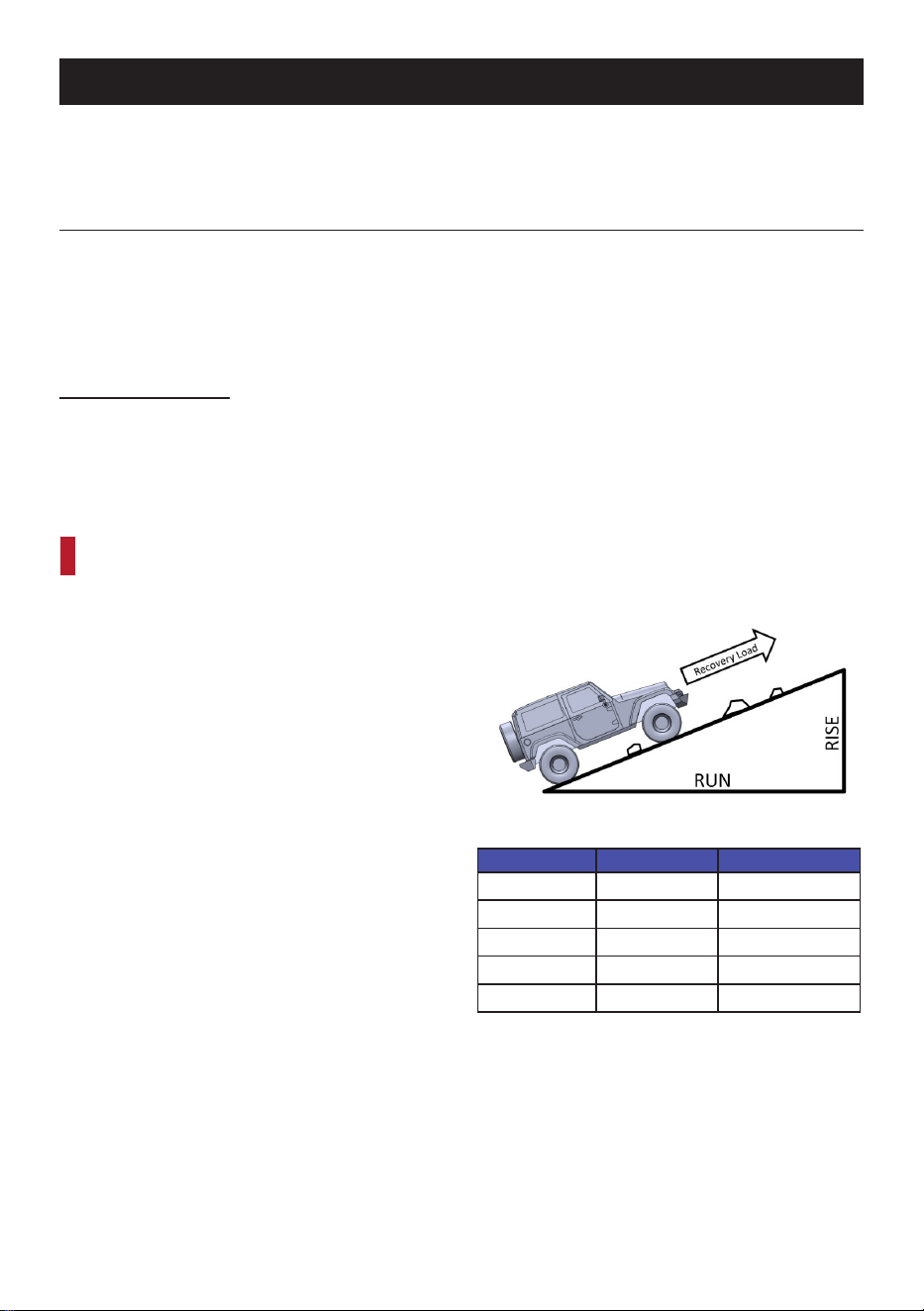
Grade Resistance
For recoveries or applications that pull a vehicle up a slope, grade resistance is a factor in the
recovery load. This is because there are many other variables to consider off-road that add
For the majority of off-road recoveries, the grade resistance
can be equal to the gross vehicle weight (GVW).
For smooth ramps used to load a trailer or other
situations that are not as varied, you can use the
following to estimate the recovery load. To
estimate load you will need the gross vehicle
• GVW can be found on the nameplate of
the vehicle, or by a weigh station scale.
• % Grade = Rise / Run
Reference the chart to find the estimated
recovery load resistance.
Grade Angle % of GVW
20% 11 20%
40% 22 37%
60% 31 51%
80% 39 62%
100% 45 71%
Page 9For technical questions, please call 1-888-866-5797.Winching
Guide
Mire Resistance
For recoveries in mud, sand, or snow, mire resistance becomes a factor. Mire resistance
is the added resistance that the soft terrain adds as the vehicle is submerged beneath
•
•
• Cab Depth = 3x GVW
A snatch block is a great
way to double the pulling
power of your winch.
Tackle Resistance
Wheel Depth Mire
Fender Depth Mire
Cab Depth Mire
Page 10 For technical questions, please call 1-888-866-5797. Winching
Guide
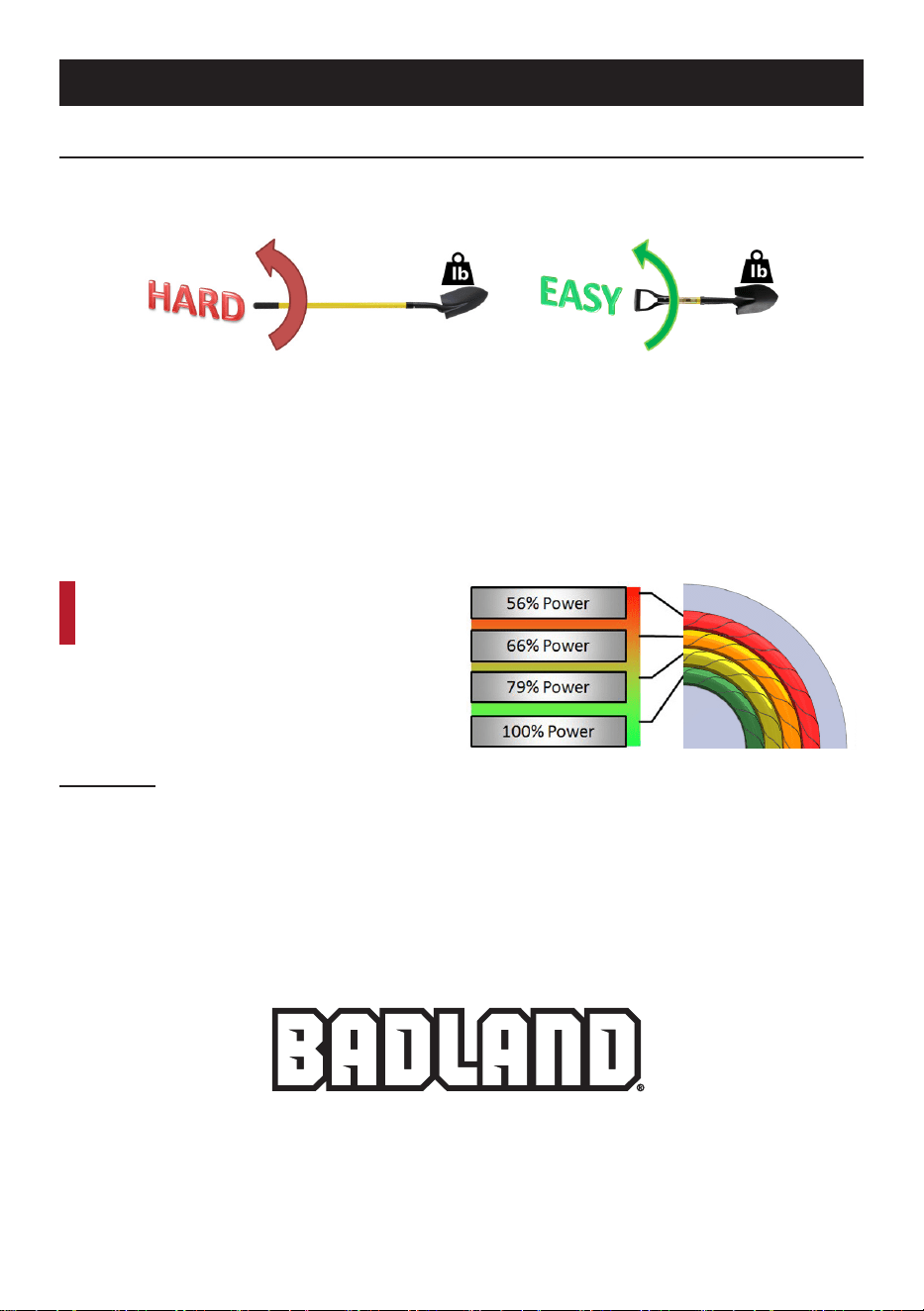
Winch Basics
Rope Layer
Imagine trying to hold a full length shovel horizontal by the
Now imagine holding a shorter shovel by the end of the handle. Maybe
not easy, but certainly easier than the full length shovel.
This is an example of how the winch must exert torque on the drum for the various
layers of rope on the drum. The outermost layer of rope is represented by the full
length shovel, and the first layer of rope is represented by the short shovel.
The winch and the vehicle electrical system have a limited amount of power
available, so it is important to use the power in the most efficient way possible.
The winch can pull to 100% full rated
load only on the first layer of rope
that touches the drum.
For a constant load, as each layer of
rope winds on, the winch must exert
more torque on the drum, because of
the added leverage of each layer.
WARNING! To prevent serious injury from
sudden detachment of the winch rope leave
at least 5 full wraps of rope on the drum.
Page 11For technical questions, please call 1-888-866-5797.Winching
Guide
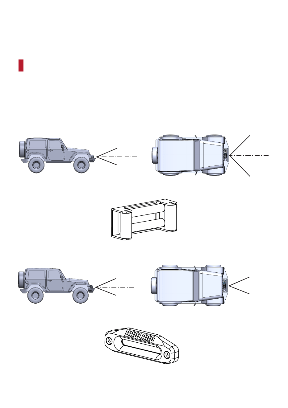
Rope Angle
Your winch is designed to handle off-angle pulls for brief periods. However, extended pulls
change the direction or move the anchor point.
Try to winch with the rope as straight into the winch as possible.
If you do have to winch off-angle, do not exceed the angles shown below.
Spotter must be outside danger zone. Have spotter watch for even winding of rope on
drum. If rope starts winding unevenly on the drum, stop winching and adjust rigging
or vehicle position. Freespool the winch to remove the rope bunching on the drum
15
º
MAX
15
º
MAX
45
º
MAX
45
º
MAX
Roller Fairlead Maximum Winching Angles
Roller Fairlead
15
º
MAX
15
º
MAX
15
º
MAX
15
º
MAX
Hawse Fairlead Maximum Winching Angles
Hawse Fairlead
Page 12 For technical questions, please call 1-888-866-5797. Winching
Guide
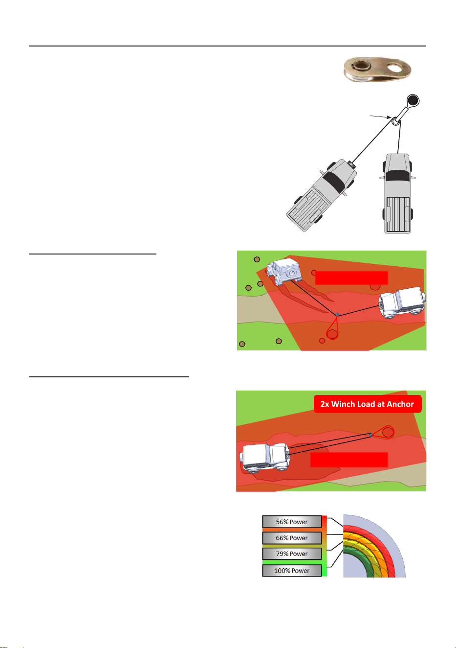
Snatch Blocks
of vehicle recoveries.
of a rope. In the diagram a 4 ton vehicle is attached to a rope
Notice that the tension in each of the ropes is
must carry the combined load of the ropes.
This is a simplified example neglecting the angle of
pull of the ropes. As the angle between the ropes
Example 1: Direction Change
In a direction change situation, the objective is
to pull from a direction that has a greater impact
does not provide any increase to the recovery
force but it does change the direction of the pull.
Example 2: Recovery Force Increase
force than the winch can provide, a double line
pull should be used. This can help reduce the
load on the winch and decrease the electrical
load on the vehicle.
In this example the weight becomes the
is again connected to an anchor point. The
usefulness of this rigging is to leverage
the doubled force of the two ropes that the
force to be double that of a single line pull.
Additionally the double line rigging will require
more rope off the drum, allowing the winch to
pull force.
8T
Snatch Block
Winching
Vehicle
Recovery
Vehicle
4T
4T
4T
Load
Page 13For technical questions, please call 1-888-866-5797.Winching
Guide
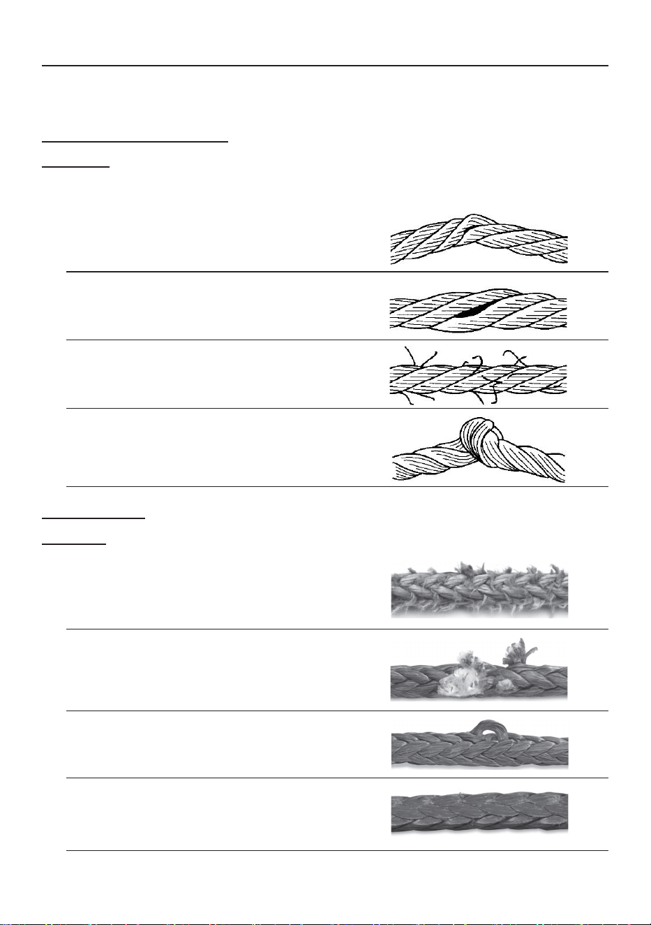
Rope Inspection
The rope on the winch is the highest wear item in the winching system, and the
most dangerous if not inspected regularly. Wire rope and synthetic rope have
WARNING! To prevent serious Injury from razor sharp broken strands, wear heavy-
duty work gloves when handling wire rope. Do not run hands along wire rope, even
•
•
•
•
Synthetic Rope
CAUTION! Wear work gloves to protect from cuts from
debris when working with synthetic rope.
•
be replaced; minor abrasion or a
•
•
•
load to remove the compression.
Page 14 For technical questions, please call 1-888-866-5797. Winching
Guide
Setup
WARNING! To prevent serious injury from electrical fire: check the
electrical cables to your winch for abrasion or heat damage before
use. Replace worn or damaged cables immediately.
1.
vehicle that is generally straight on and
that allows for sufficient rope out to
obtain maximum power from the winch.
2. PUT ON GLOVES. Regardless of
gloves are always a good idea.
3. Place the winch into freespool.
Rigging
1.
WARNING! To prevent serious injury from sudden detachment of the
winch rope leave at least 5 full wraps of rope on the drum.
2. Secure the winch rope to the anchor point.
Do not wrap the winch rope directly around
3.
the rigging.
4.
THE HOOK LATCH MUST CLOSE.
5. Place a winch damper or other heavy object
on the line, 1/3 of the total distance from the
Use double line rigging whenever practical to prevent
overloading and overheating of the winch.
Page 15For technical questions, please call 1-888-866-5797.Winching
Guide
6. ESTABLISH A DANGER ZONE. At least
sure no people enter during the winching
operation or when the line is under tension.
WARNING!
Do not allow anyone to stand near
the rope, or inline with the rope behind the
winch or anchor point while it is under power. If the rope should slip or break, it can
suddenly whip back towards the winch or anchor, causing a hazard for anyone in the
area established by the danger zone. Stand well to the side when winching.
Winching
For self recovery:
Place winch vehicle in NEUTRAL
•
Keep foot OFF brake
For other vehicle recovery:
Place winch vehicle in NEUTRAL
•
Keep foot ON brake
1. Re-engage the freespool clutch, and plug-
in or connect the remote to the winch.
2.
Designate one person as a spotter to watch
rope is spooling on the drum correctly.
3. Perform the winching operation, with the
vehicle in NEUTRAL or DRIVE. Watch your
spotter, and monitor the battery voltage
while winching. Increase the engine
RPM to raise the battery voltage level.
4. When the vehicle is recovered engage
and wind the rope fully into the winch
USING THE HOOK STRAP.
5. Unplug or disconnect the remote and
store it in the vehicle for the next use.
NOTICE: Your winch is designed
for INTERMITTENT USE ONLY. If
the motor stalls, STOP OPERATION
and use a snatch block.
Duty Cycle (Duration of Use)
Avoid damage to the Winch by not winching for more than the prescribed
duty cycle time. The Duty Cycle defines the amount of time, within a
15 minute period, during which a Winch can operate at its maximum
capacity without overheating. For example, a Winch with a
5% duty cycle at its maximum load must be allowed to rest
for at least 14 minutes, 15 seconds after every 45 seconds
of continuous operation. Failure to carefully observe duty
cycle limitations can easily over-stress a Winch contributing
to premature Winch failure.
at least
14 minutes,
15 seconds
of rest
45 seconds winching
Page 16 For technical questions, please call 1-888-866-5797. Winching
Guide
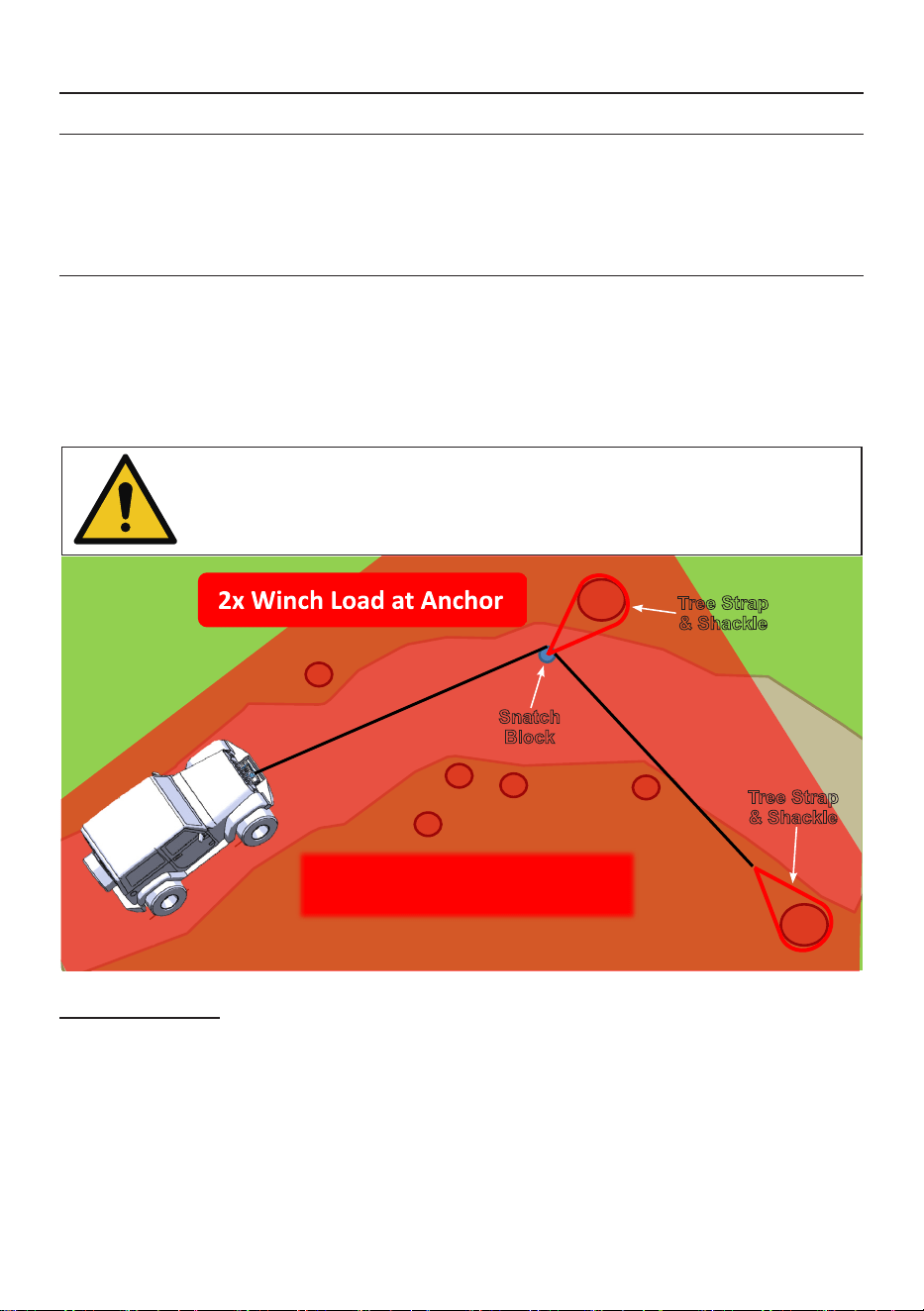
Overview
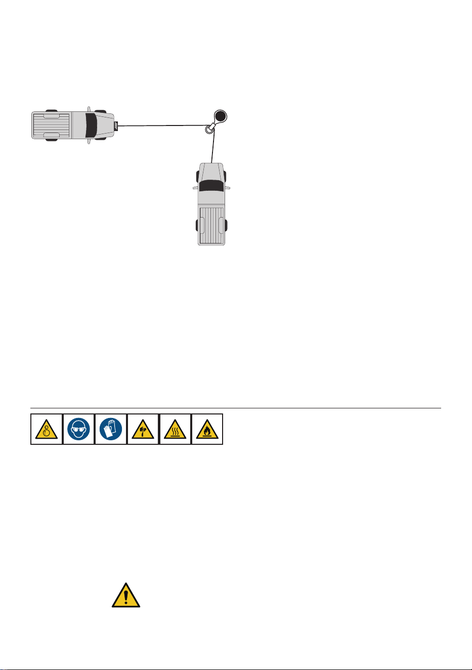
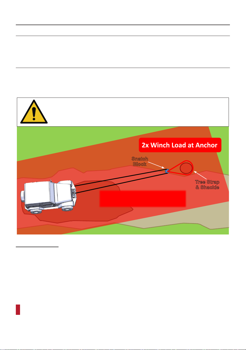
Not every recovery can be handled with a straight line pull. Often the most effective recovery
a single line pull, the pull direction can be changed without moving the winching vehicle.
Around a Corner
pull harder, it also allows the vehicle to remain connected to the farthest anchor once the
Pay special attention to the danger zone, since it is much larger than a straight line pull.
USE ALL OF THE PRECAUTIONS AND STEPS
Snatch
Block
Tree Strap
& Shackle
Tree Strap
& Shackle
Rigging Needed:
•
•
•
Page 17For technical questions, please call 1-888-866-5797.Winching
Guide
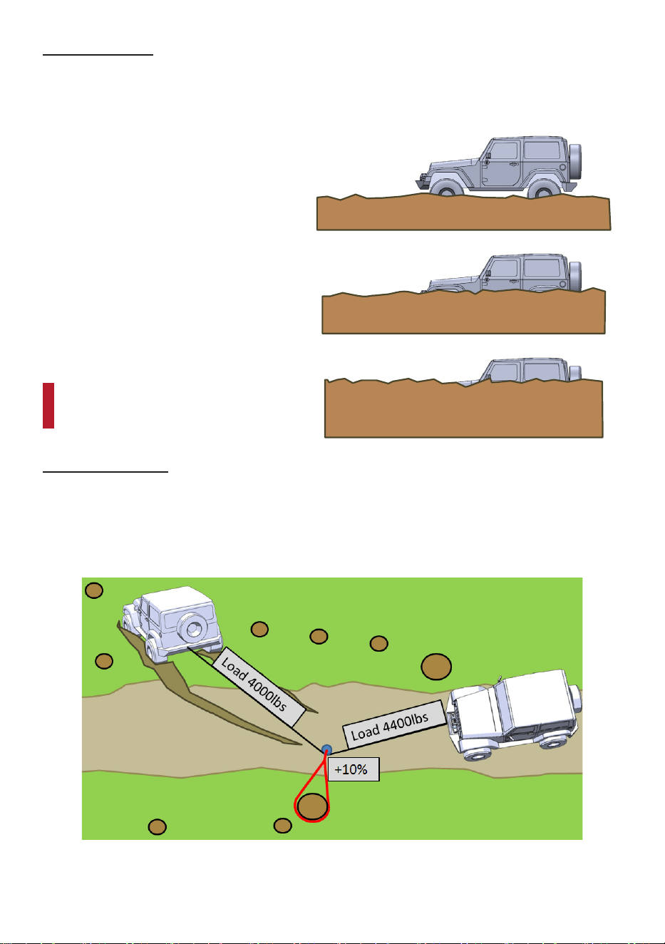
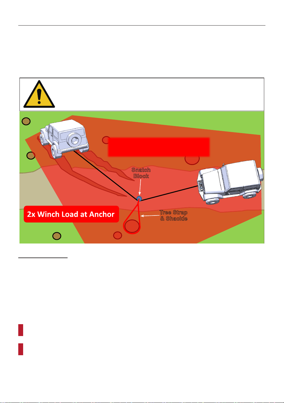
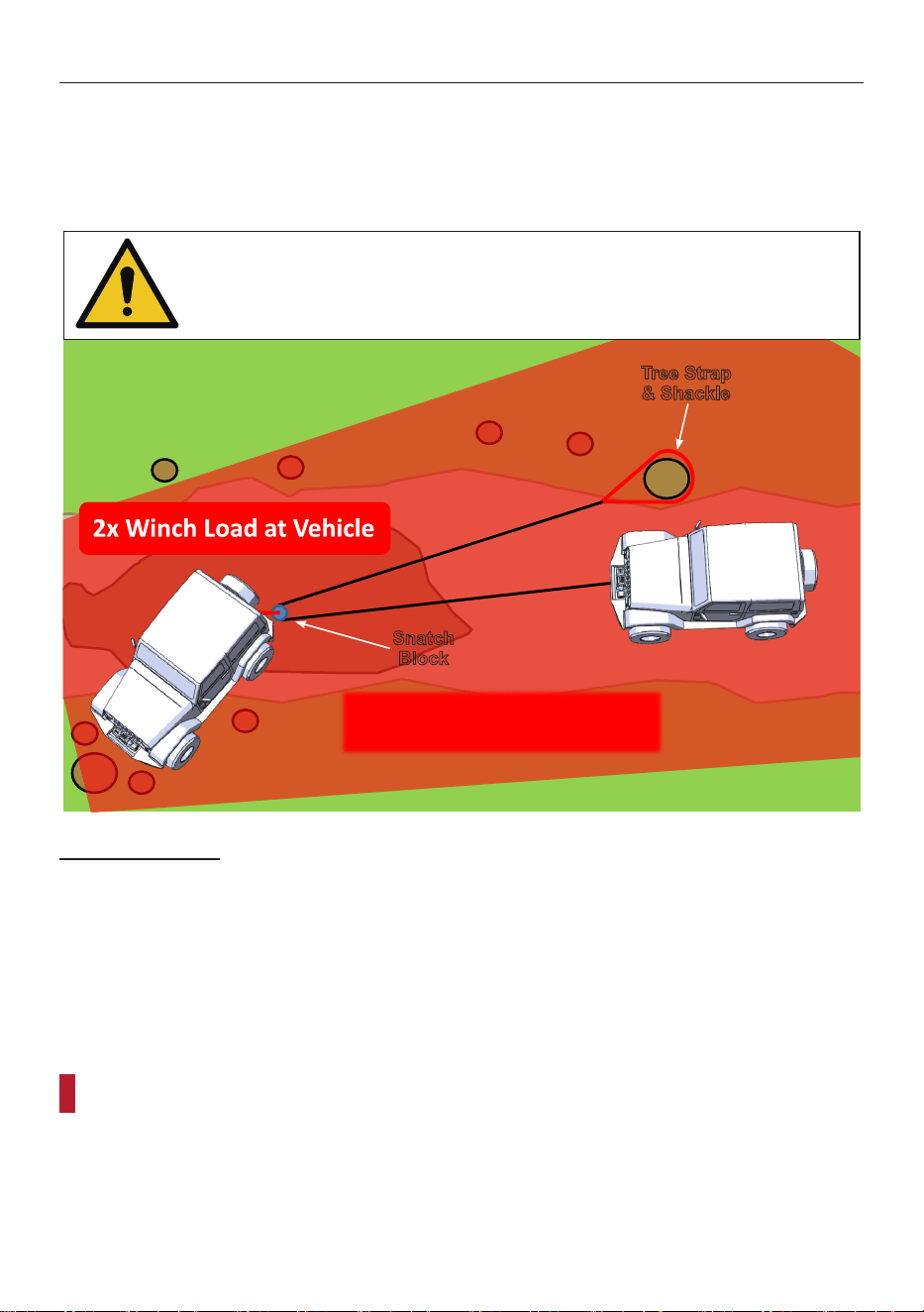
Vehicle Off Trail
vehicle to the road is using an angled pull since this pulls the vehicle most directly onto the
perform the recovery.
Pay special attention to the danger zone, since it is much larger than a straight line pull.
USE ALL OF THE PRECAUTIONS AND STEPS
Snatch
Block
Tree Strap
& Shackle
Rigging Needed:
•
•
•
For self recovery:
Place winch vehicle in NEUTRAL
•
Keep foot OFF brake
For other vehicle recovery:
Place winch vehicle in NEUTRAL
•
Keep foot ON brake
Page 18 For technical questions, please call 1-888-866-5797. Winching
Guide
Double Line Winching
Overview
Certain recoveries require more force than a single line pull can provide. In these situations
a double line pull is necessary to develop enough force to recover the vehicle.
For self recovery efforts that require more force than a single line pull can provide, use a
rated to withstand the estimated load to recover the vehicle.
USE ALL OF THE PRECAUTIONS AND STEPS
Snatch
Block
Tree Strap
& Shackle
Rigging Needed:
•
•
•
For self recovery:
Place winch vehicle in NEUTRAL
•
Keep foot OFF brake
Page 19For technical questions, please call 1-888-866-5797.Winching
Guide
This can be especially helpful in low traction conditions such as snow or mud.
Pay special attention to the danger zone, since it is much larger than a straight line pull.
USE ALL OF THE PRECAUTIONS AND STEPS
Snatch
Block
Tree Strap
& Shackle
Rigging Needed:
•
•
•
For other vehicle recovery:
Place winch vehicle in NEUTRAL
•
Keep foot ON brake

26541 Agoura Road • Calabasas, CA 91302 • 1-888-866-5797