www.barska.com
LIMITED LIFETIME WARRANTY
BINOCULARS
BARSKA® Optics, as manufacturer, warrants this new precision optical product to be
free of original defects in materials and/or workmanship for the length of time specifi ed
by this warranty. This warranty does not include damage caused by abuse, improper
handling, installation, maintenance, normal wear-and-tear, unauthorized repairs or
modifi cations and tampering in anyway.
This warranty is limited to the original purchaser and is not transferable. This warranty
applies only to products purchased in the United States of America and Canada.
In the event of a defect within 30 days, the consumer must return the defective unit to
the BARSKA dealer (the place of purchase) at his/her own expense.
Beyond 30 days, BARSKA products should be sent to the following address for
warranty repairs. Products must be packed carefully and sturdily to prevent damage in
transit, and returned freight prepaid to:
For additional and updated information please visit our website at www.barska.com
Please e-mail [email protected] or call 1-888-666-6769 for Return Merchandise
Number (RMA#) before any returns.
NOTE: All merchandise received without a valid RMA # will be returned to shipper at
his/her own expense.
Please include all of the following when returning BARSKA products for service and/or
replacement:
1. Please write your complete details
(Name, Address, Telephone #, E-mail address, RMA#, etc.)
2. Purchase receipt or Proof of Purchase. (Original/Copy)
3. A brief explanation of the defect.
4. A Check/Money Order of $20.00 to cover inspection, shipping and handling.
*Please allow 6-8 weeks for delivery.
This product will either be replaced or repaired at the discretion of the warrantor. If it’s
a discontinued item, we will replace the product with an equivalent product. Should
the repair not be covered by this warranty, an estimate will be sent for your approval.
Non-warranty repairs or refurbishing of your optical products are always provided at a
reasonable cost.
BARSKA® Optics shall not be liable for any consequential, incidental and/or contingent
damages whatsoever. We will NOT pay shipping, insurance or transportation charges
from you to us, or any import fees, duties and taxes.
This warranty supersedes all previous BARSKA® Optics warranties.
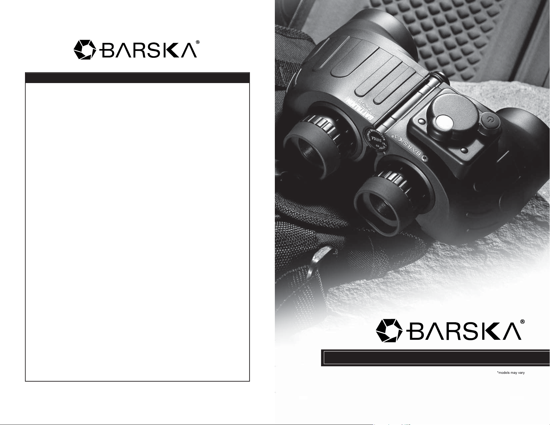
Battalion Binoculars
BC3384/13
©2013 BARSKA
®
Pomona, CA 91767, USA
www.barska.com
BARSKA® OPTICS
855 Towne Center Drive
Pomona, CA 91767
CAUTION: DIRECTLY VIEWING THE SUN OR ANY LIGHT SOURCE WITH
THIS OPTICAL DEVICE CAN CAUSE PERMANENT EYE DAMAGE.
www.barska.com
Battalion Binoculars
1
Battalion Binoculars
2
www.barska.com
I. EYE ADJUSTMENTS HOW TO ADJUST FOR DISTANCE
BETWEEN YOUR EYES
The distance between the eyes, called “interpupillary
distance” (IPD), varies from person to person. To achieve
perfect alignment of lens to eye, follow these simples steps.
1. Hold your binocular in the normal viewing position.
2. Grasp each barrel fi rmly. Move the barrels closer together or further apart until you see
a single circular fi eld. Always re-set your binocular to this position before using.
II. EYECUPS
Your binocular is fi tted with either rubber roll-down or rubber pop-up eyecups designed
for your comfort and to exclude extraneous external light. If you wear sun/eye glasses,
roll down the eyecups. This will bring your eyes closer to the binocular lens thus providing
improved fi eld of view.
III. FOCUSING
Battalion models feature individual focus systems.
INDIVIDUAL FOCUS
1. Adjust interpupillary distance. Make a note of the number which appears on the central
hinge scale. Always re-set your binocular to this position before using.
(To see a single circular fi eld.)
2. Cover right objective (front) lens with your hand. Rotate left eyepiece until image
is focused.
3. Follow the same procedure for the right eye. The eyepiece should be turned in a
counter-clockwise direction for more distant objects. With the image now in focus,
make a note of the diopter setting for future use.
IV. WATERPROOF/FOG-PROOF
Your binocular is designed and built utilizing the latest waterproof and fog-proof
technology. Waterproof models are O-ring sealed for complete protection. Fog proof
protection is achieved from dry nitrogen purging to remove all internal moisture.
V. TRIPOD ADAPTER
If your binocular is equipped with a built in tripod adapter fi tting, you will have to unscrew
the cover screw located at the base of the binocular hinge.
VI. INSTRUCTIONS FOR CARE
If handled with care, this binocular will provide years of
trouble-free service. Like any fi ne optical instrument your
binocular should be given sensible care. Non waterproof
models should not be exposed to excessive moisture.
1. Keep the lens covers on the lenses when binoculars are
not in use.
2. Store binoculars with the eyecups up. Thus avoiding excessive stress and wear on the
eyecups in the down position.
3. Avoid banging and dropping.
4. Store in a cool, dry place.
VII. CLEANING
1. Blow away any dust or debris on the lens (or use a soft lens brush)
2. To remove dirt or fi ngerprints, clean with a soft cotton cloth rubbing in a circular motion.
Use of a coarse cloth or unnecessary rubbing may scratch the lens surface and
eventually cause permanent damage.
3. For a more thorough cleaning, photographic lens tissue and photographic-type lens
cleaning fl uid or isopropyl alcohol may be used. Always apply the fl uid to the cleaning
cloth never directly on the lens.
NEVER attempt to clean
your binocular internally
or try to take it apart.
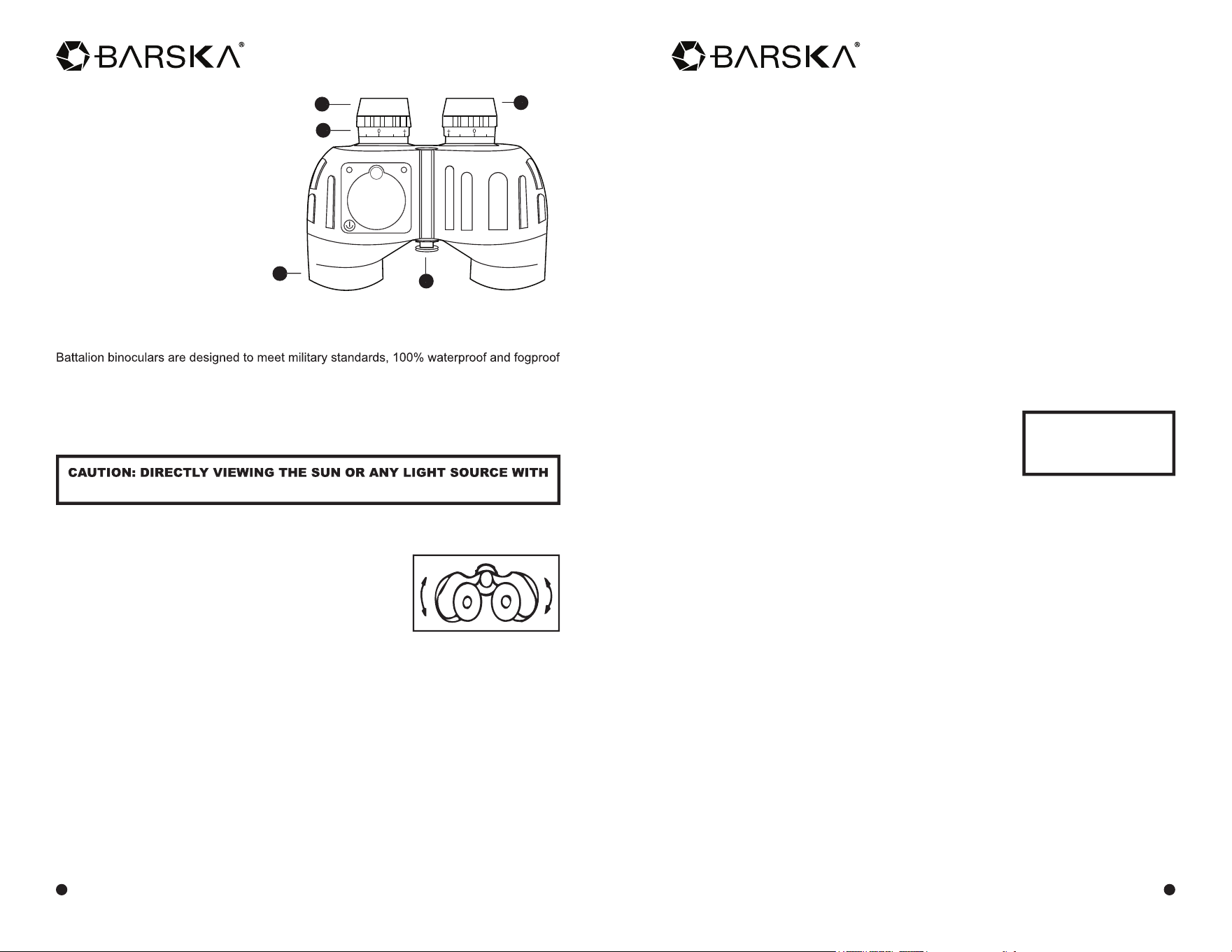
Basic Parts of a Binocular
1. Eyepiece
2. Individual Focus
3. Eye Cups
4. Objective Lens
5. Tripod Adaptable Fittings
*models may vary
1
2
3
5
4
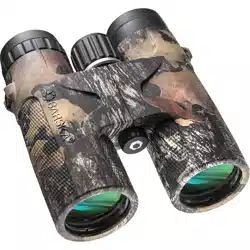
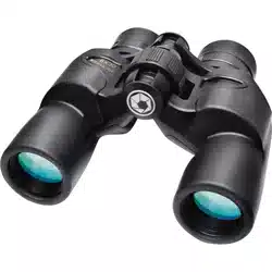
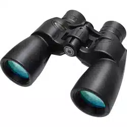
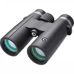
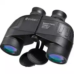
Battalion binoculars are designed to meet military standards, 100% waterproof and fogproof
and are fully rubber armored for shock protection and a comfortable secure grip. Whether
you’re ashore or on the water, these binoculars are designed to perform in the most
demanding conditions. Choose from compact or full-size models with or without an internal
rangefi nder and compass.
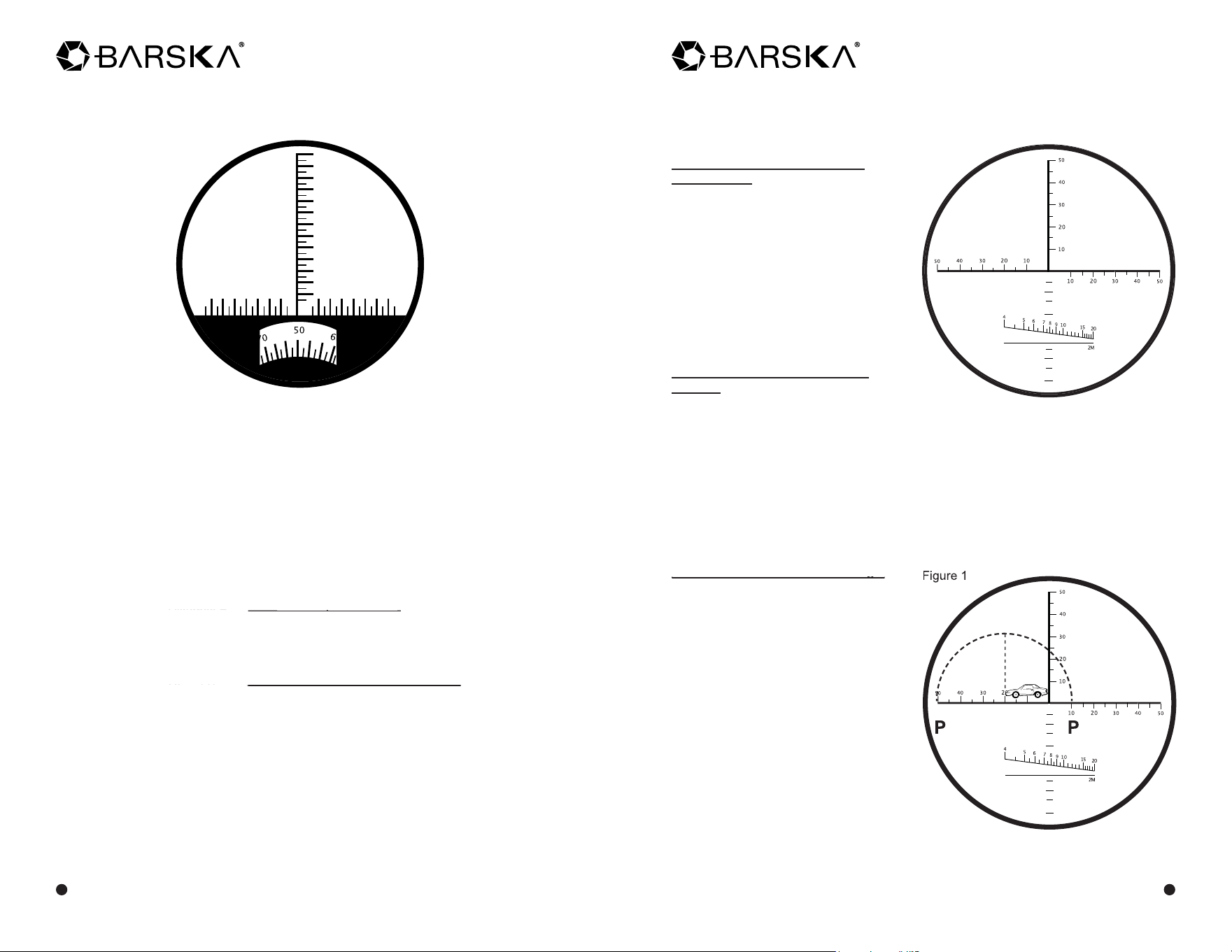
How To Read the Horizontal and
Vertical Lines
There are vertical and horizontal lines
on the reticle. Each small division
on both vertical and horizontal lines
represents 5 mils and each big
division represents 10 mils (one
circularity angle=6400 mils) One
circular angle equals 1 degree of
angle, equals 1 minute of angle,
equals 60 seconds of angle,
equals 6400 mils.
How To Use The Reticle Measure
Azimuth
An azimuth of a body is the arc of the horizon intercepted between the north or south
point and the foot of the vertical circle passing though the body. It is calculated in
degrees from either the north or south point clockwise entirely around the horizon.
Azimuth of a current is the direction toward which it is fl owing, and is usually calculated
from the north point.
A mil’s reticle can measure the azimuth angle, upper and lower angle, distance and size
of an object or target. The visual distance reticle lines can measure the distance of
normal object easily on the basis that the object to be measured is a least 2
meters (6 feet) in height.
How To Measure The Azimuth Angle
How To Measure The Azimuth Angle
The azimuth angle is the angle
included between two objects to be
measured at the horizontal direction of
the binocular. (Or two ends of one
object at horizontal direction)
When the azimuth of two targets is
smaller than the azimuth measuring
range (-50~+50 mils) inside the
binoculars, aim the scale line at one
end of the reticle at the target then read
the value of the scale at which another
target was located on the reticle. The
value is the measured azimuth mil.
As shown in
fi g. 1, the azimuth of the
target (car) is 0-20 mils. The azimuth
between the targets (p-p) is 0-60 mils.
www.barska.com
www.barska.com
HOW TO USE INTERNAL RANGEFINDER
AND DIRECTIONAL COMPASS RETICLE
select models
To use the rangefi nder scale, you will need to know either (1) the size or (2) the distance
of the object. When the size of the object is known, the rangefi nder scale indicates the
distance to the object. When the distance to the object is known, the rangefi nder scale tells
you its size. Each mark on the vertical scale has a value of 5 MIL (1 MIL is equivalent to
an angle that can determine an object one meter in height at a distance of 1000 meters.)
Therefore, if a navigation chart gives the height of an object, by sighting on it and counting
the number of MILs, you can determine how far away the object is. The horizontal scale
should be aligned with the base of the object that you are sighting on. The increments on
the horizontal scale can be used to determine the distance to the object if the width of the
object is known and calculated using the formula.
1. To measure the DISTANCE (object size must be determined):
1000 x Object Size
100 x Object Size
Distance =
Rangefi nder Scale Reading
2. To measure the SIZE (object distance must be determined):
Distance x Rangefi nder Scale Reading
Distance x Rangefi nder Scale Reading
Object Size =
100
USING THE DIRECTIONAL COMPASS
The compass scale is in one degree increments. It is aligned with the vertical range fi nding
scale. North is represented as 0°, East as 90°, South as 180° and West as 270°. When
using the compass, bear in mind the local variation between magnetic North and true North.
NOTE: Compass does not operate in southern hemisphere
Battalion Binoculars
3
Battalion Binoculars
4
HOW TO USE INTERNAL RANGEFINDER RETICLE
select models
When the target’s upper and lowers parts of the is than the mils on the reticle, it can be
measured in steps and the angle can be obtained by summing up the value of each
step. (The process will be similar to the one that is discussed in the linear
measurements)
How To Use The Reticle To Measure Distance
The distance measurement of a target can be calculated by using the mil reticle.
The formula of distance measurement: D(km) =H(m)/K
D = Distance between the observer and the target (km)
H= Height of the target (m)
K= Upper and lower angle of azimuth of the target measured with the reticle
of binoculars (mil)
Distance (km) =
Height (m)
Height (m)
Upper and lower angle of azimuth target (mils)
Distance (km) =
Upper and lower angle of azimuth target (mils)
Distance (km) =
When measuring the distance, fi rst, estimate the height or width of the target, then
measuring upper and lower angle of the target. Accordingly, you can calculate the
distance between the observer and the target using the formula
For example: There is a person whose height is 1.70m (H=1.70m)
The upper and lower angle of the adult is 0-40 mils (K=0-40)
D=H/K = 1.7/40 = 0.0425km x 1000 =42.5m
Therefore the distance between the observer and the person is 42.5m
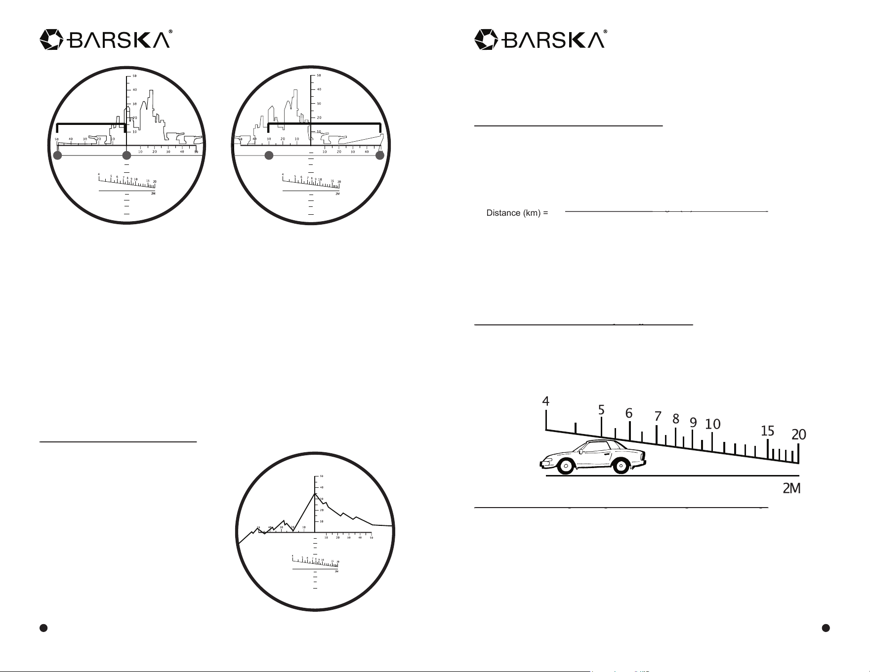
How To Measure Distance Directly Using The Reticle
How To Measure Distance Directly Using The Reticle
For example, if the target is 2 meters in height, place the lower part of the target at the
horizontal line on the reticle with the upper top part of the target against the angled scale
line. The reading on the top of the target where the top of the target or image touches
the top of the angled scale line is the distance between the target and the observer (line
value: 100m). As shown in fi gure 4, the distance between the target and the observer
is 550m.
How To Measure A Target’s Height And Width Using Azimuth Readings
How To Measure A Target’s Height And Width Using Azimuth Readings
According to the formula for distance measurement, you can calculate the height using
H=DxK
When measuring the size, you fi rst estimate the distance to the target, then measure the
azimuth or upper and lower angle. With these measurements, you can calculate the
height of the target using the formula.
For example: the distance is 0.6km between the observer and the target. You can
measure that the azimuth is 60 (0-60) and the upper and lower angle is 30 (0-30).
Using the formula you can get:
Height: H=0.6 x 30=18m Width: H=0.6 x 60=36m
When the azimuth of two targets is bigger than azimuth measuring range
(-50~+50 mils) inside the binoculars, on the target can be selected to make the
necessary measurements in a step by step fashion. The sum of the value from each
step is used to obtain the measured azimuth. As shown in fi g. 2, the azimuth of target
(cruiser) is 130 mils (50+80=130).
When the azimuth of a target is longer than the azimuth measuring range (-50~+50 mils)
inside the binoculars, you can visually calculate the total azimuth mils by using the
vertical line on the reticle by placing the image in a position where the vertical line splits
the image. You will need to take two image readings. Mentally, consider the horizontal
with three reference points. Point A is the 50 mil point on the far left side. Point B is
where the vertical line intersects the horizontal line. Point C is the far right 50 mil point.
Now your fi rst reading on the image will be the mils from point A to B with point A on
the far left part of the image (fi g. 2). Your second reading will be from point C to
point B where point B is now the spot on the image where point B ended after the fi rst
reading. After calculating the mils for each image, you then add them together to get the
total azimuth reading. In (fi g. 2), the ship is longer than the total 100 mils available on
the reticle. However, by doing the foregoing mil calculations, you can now obtain the
ships total mil azimuth of (50+80) 130 mils.
Upper and Lower Angle Measurement
Upper and Lower Angle Measurement
Upper and lower angle means the angle
included between any two targets (or two
ends of a target) against the vertical line of
the reticle
Upper and lower angle measurement is
similar to measuring the azimuth. When the
upper and lower angle measurement is very
small, aim the cross center of the reticle
at the lower part of the target, read the scale
value at the top of the target. The value
is the measured mils of the angle included
between the upper and lowers parts. As
shown in fi g. 3, the value of the lower parts
is 40, the angle included between the upper
and lowers parts of the target is 0-75 (75mils).
www.barska.com
www.barska.com
Battalion Binoculars
5
Battalion Binoculars
6
Figure 2
Figure 3
Figure 4
A B
50
80
B C
First Reading
Second Reading