MIG/TIG & MMA (ARC/STICK) INVERTER
WELDER
MODEL NO’S: MINIMIG120i (120A) , MINIMIG160i (160A)
Thank you for purchasing a Sealey product. Manufactured to a high standard, this product will, if used according to these instructions,
and properly maintained, give you years of trouble free performance.
IMPORTANT: PLEASE READ THESE INSTRUCTIONS CAREFULLY. NOTE THE SAFE OPERATIONAL REQUIREMENTS, WARNINGS & CAUTIONS. USE
THE PRODUCT CORRECTLY AND WITH CARE FOR THE PURPOSE FOR WHICH IT IS INTENDED. FAILURE TO DO SO MAY CAUSE DAMAGE AND/OR
PERSONAL INJURY AND WILL INVALIDATE THE WARRANTY. KEEP THESE INSTRUCTIONS SAFE FOR FUTURE USE.
1. SAFETY
1.1. ELECTRICAL SAFETY
WARNING! It is the user’s responsibility to check the following:
9 Check all electrical equipment and appliances to ensure that they are safe before using. Inspect power supply leads, plugs and all electrical
connections for wear and damage. Sealey recommend that an RCD (Residual Current Device) is used with all electrical products.
Electrical safety information. It is important that the following information is read and understood:
9 Ensure that the insulation on all cables and on the appliance is safe before connecting it to the power supply.
9 Regularly inspect power supply cables and plugs for wear or damage and check all connections to ensure that they are secure.
IMPORTANT: Ensure that the voltage rating on the appliance suits the power supply used and that the plug is fitted with the correct fuse.
8 DO NOT pull or carry the appliance by the power cable.
8 DO NOT pull the plug from the socket by the cable.
8 DO NOT use worn or damaged cables, plugs or connectors. Ensure that any faulty item is repaired or is replaced immediately by a
qualified electrician.
If the cable or plug is damaged during use, switch off the electricity supply and remove from use.
Ensure that repairs are carried out by a qualified electrician.
8 DO NOT use with medical implants. Ensure the unit is correctly earthed via a three-pin plug.
9 Cable extension reels. When a cable extension reel is used it should be fully unwound before connection. A cable reel with an RCD fitted
is recommended since any product which is plugged into the cable reel will be protected. The section of the cable on the cable reel is
important and should be at least 1.5mm², but to be absolutely sure that the capacity of the cable is suitable for this product and for others
that may be used in the other output sockets, we recommend the use of 2.5mm² section cable.
WARNING! Be very cautious if using a generator to power the welder. The generator must be self-regulating and stable with regard to
voltage, wave form and frequency. The output must be greater than the power consumption of the welder. If any of these requirements is
not met the electronics within the welder may be affected.
NOTE: The use of an unregulated generator may be dangerous and will invalidate the warranty on the welder.
WARNING! The welder may produce voltage surges in the mains supply which can damage other sensitive equipment (e.g. computers).
To prevent this happening, it is recommended that the welder is connected to a power supply that does not feed any sensitive equipment.
IMPORTANT: If using welder to full capacity, we recommend a 16amp supply. We recommend you discuss the installation of a 16amp
industrial round pin plug and socket with your electrician.
1.2. GENERAL SAFETY
▲ DANGER! Unplug the welding set from the mains power supply before performing maintenance or service.
9 Keep the welding set and cables in good working order and condition. Take immediate action to repair or replace damaged parts.
9 Use genuine parts and accessories only. Unapproved parts may be dangerous and will invalidate the warranty.
9 Use an air hose to regularly blow out any dirt from the liner and keep the welding set clean for best and safest performance.
9 Check and spray the gas cup and contact tip regularly with anti-spatter spray, available from your Sealey stockist.
9 Locate the welding set in a suitable work area. Ensure that the area has adequate ventilation as welding fumes are harmful.
9 Keep work area clean, tidy and free from unrelated materials. Also ensure the working area has adequate lighting and that a fire
extinguisher is at hand.
WARNING! Use welding head shield to protect eyes and avoid exposing skin to the ultraviolet rays given off by electric arc.
Wear safety welding gauntlets.
9 Remove ill fitting clothing, remove ties, watches, rings and other loose jewellery and contain long hair.
9 Ensure the workpiece is correctly secured before welding.
9 Avoid unintentional contact with the workpiece. Accidental or uncontrolled use of the torch may be dangerous and will wear the nozzle.
9 Keep unauthorised persons away from the work area. Any persons working within the area must wear a protective head shield and gloves.
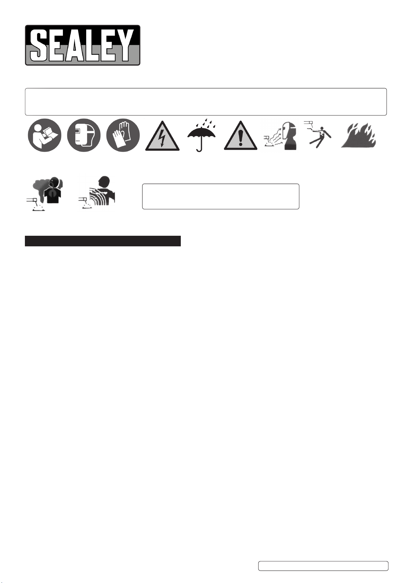
Refer to
instruction
manual
Wear a
welding
mask
Wear protective
gloves
Warning!
Electricity
Shock hazard
Warning!
Keep away
from rain
Caution
required
Arc rays can
burn eyes and
injure skin
Breathing welding
fumes can be
hazardous to your
health
Electric shock
from welding
electrodes can
kill
Electromagnetic
fields can cause
pacemaker
malfunction
Welding sparks
can cause
explosions or
fire
Original Language Version
© Jack Sealey Limited
NOTE:
Diagrams of components are for reference only. There may
be detail differences in the components of your welder but
these will not affect its operation.
MINIMIG120i MINIMIG160i Issue 1 14/10/24
9 Operators must receive adequate training before using the welding set.
9 Stand correctly keeping a good footing and balance, ensure the floor is not slippery and wear non-slip shoes.
8 DO NOT operate the welding set if it or the cables are damaged and DO NOT attempt to fit any unapproved torches or other
components to the welding set.
8 DO NOT get the welding set wet or use in damp or wet locations or areas where there is condensation. DO NOT use to thaw pipework.
▲ DANGER! DO NOT weld near flammable solids, liquids or gases and DO NOT weld containers or pipes which have held
flammable materials. Avoid welding materials which have been cleaned with chlorinated solvents or welding near such solvents.
8 DO NOT stand the welding set on a metal workbench, car bodywork or similar. DO NOT use welder on uneven ground or surfaces.
8 DO NOT touch any live metal parts of the torch or electrode while the welding set is switched on.
8 DO NOT pull the welding set by the cable, or the torch. Protect cables from sharp or abrasive items. DO NOT bend, strain or stand on
cables or leads.
9 Protect from heat. Long lengths of slack must be gathered and neatly coiled. DO NOT place cables where they endanger others.
8 DO NOT touch the torch or workpiece immediately after welding as they will be very hot. Allow to cool.
8 DO NOT operate the welding set while under the influence of drugs, alcohol or intoxicating medication, or if tired.
9 When not in use store the welding set in a safe, dry, childproof area. Hand carry the unit when power is disconnected and the unit is cool.
1.3. VOLTAGE BETWEEN ELECTRODE HOLDERS OR TORCHES
Working with more than one welding machine on a single piece or on pieces that are connected electrically may generate a
dangerous amount of no-load voltage between the two electrode holders or torches, the value of which may reach double the
allowed limit. Measuring instruments should be used to determine the existence of a risk and suitable precautions taken.
1.4. ELECTROMAGNETIC INTERFERENCE
The electromagnetic fields generated by the welding process may interfere with the operation of electrical and electronic equipment.
Users of vital electronic and electrical devices such as pacemakers and respirators are advised not to remain in the vicinity of an
operating welding set. If in doubt seek medical advice before entering a welding area. Users of such devices should not operate
the welding set. This welding set complies with the requirements of the technical standard for the use of this type of product, only and
exclusively in industrial environments and for professional purposes. It is not guaranteed to meet electronic compatibility requirements
in the home.
1.5. GAS SAFETY
9 Store gas cylinders in a vertical position only and ensure that the storage area is correctly secured.
8 DO NOT store gas cylinders in areas where the temperature may exceed 50°C.
8 DO NOT use direct heat on a cylinder. Always keep gas cylinders cool.
8 DO NOT attempt to repair or modify any part of a gas cylinder or valve.
8 DO NOT puncture or damage a cylinder.
8 DO NOT obscure or remove any official labels on a cylinder.
9 Always check the gas identity before use.
9 Avoid getting gas cylinders oily or greasy.
8 DO NOT lift a cylinder by the cap, guard or valve.
8 Always keep caps and guards in place and close valve when not in use.
2. INTRODUCTION
IGBT Inverter fan-cooled DC power supply for MIG/TIG and MMA/ARC welding applications. Multi-functional welder bringing together MIG/
TIG and MMA application all into one compact unit ideal for workshops, garages, bodyshop’s and mobile technicians. Ultra-compact and
lightweight weighing just 6.9kg and supplied with handy carry strap making this unit highly portable allowing the welder to be taken to the job
at hand. Featuring hot start, anti-stick, forced air cooling and thermal cut out protection. Supplied with xed non-live MIG torch, 1.4m earth
cable/clamp, 1.6m electrode holder.
IMPORTANT: These instructions contain information you require to prepare your machine for welding, together with a maintenance and
troubleshooting section. If you have no previous experience the instructions are not intended to show you how to become a welder. We
recommend that you seek training from an expert source.
3. SPECIFICATION
*IMPORTANT: If using welder to full capacity, we recommend a 16amp supply. We recommend you discuss the installation of a 16amp
industrial round pin plug and socket with your electrician.
Model Minimig120i Model Minimig160i
Welding Current 10-120A Welding Current 10-160A
Duty Cycle MIG 120A@60% Duty Cycle MIG 160A @ 60%, 124 @100%
Duty Cycle mma/arc 120A@60% Duty Cycle mma/arc 160A @ 60%, 124 @100%
Duty Cycle TIG 120A@60% Duty Cycle TIG 160A @ 60%, 124 @100%
Wire Capacity 1kg Ø0.8/0.9/1.0mm solid wire and Ø0.8/
Ø0.9mm ux cored MIG wire,
Wire Capacity 1kg Ø0.8/0.9/1.0mm solid wire and Ø0.8/
Ø0.9mm ux cored MIG wire
Electrode Capacity 1.6-3.2mm Electrode Capacity 1.6-4mm
Plug type Bare Wire Plug type Bare Wire
Supply 230V 16A *See note above Supply 230V 16A *See note above
Absorbed Power 4.4kW Absorbed Power 4.4kW
IP Rating IP21S IP Rating IP21S
Nett Weight 6.9kg Nett Weight 6.9kg
Insulation Class H Insulation Class H
Static Characteristic Drooping Static Characteristic Drooping
Pollution Degree 3 Pollution Degree 3
EMC Classication EN60974-10: 2014+A1:2015. EMC Classication EN60974-10: 2014+A1:2015.
Original Language Version
© Jack Sealey Limited
MINIMIG120i MINIMIG160i Issue 1 14/10/24
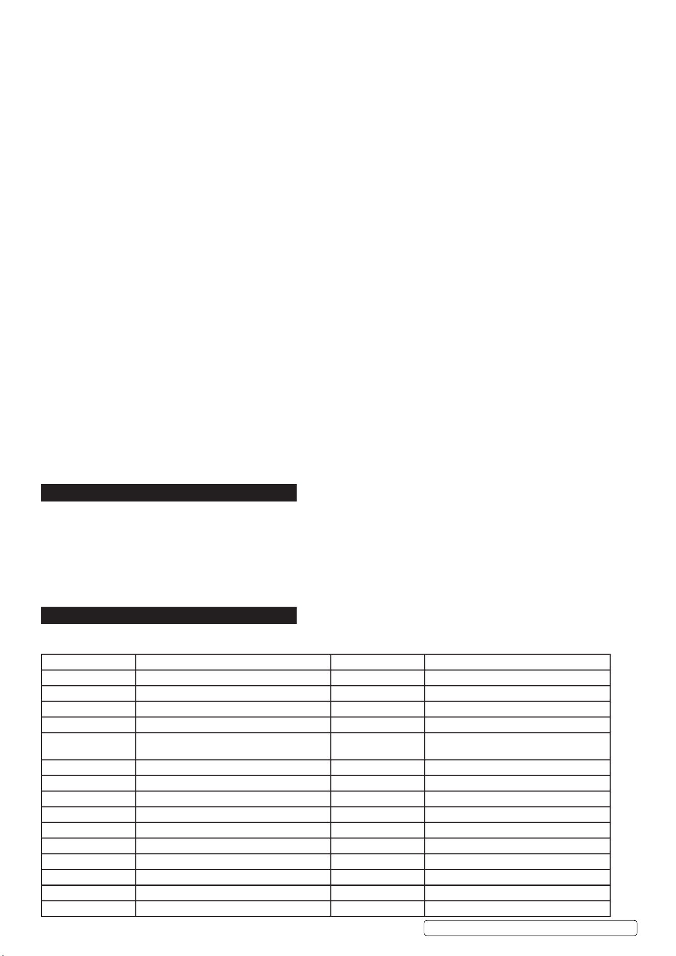
4. CONTENTS
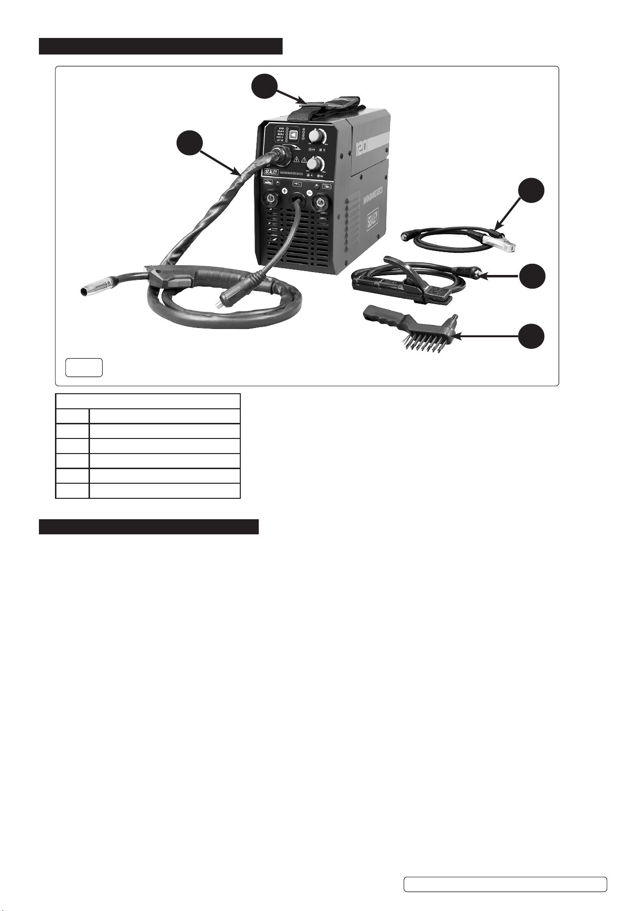
5. PREPARATION
5.1. FITTING DRIVE ROLLER (FIG.3, FIG.4)
Loosen hand wheel (g.3.1) and swing the tensioner arm 180
o
to opposite side of body.
Pivot the roller arm away from the body (g.4.1).
Depress, rotate and remove the drive roller clamp (g.3.3) and ensure the correct size guide groove for the welding medium is
lower most and aligned with the wire feed height when xing clamp back down. The size of groove is marked on the guide roller.
Swing the tensioner arm back into position and tighten the hand wheel to apply pressure to the welding wire. The pressure may need
adjusting during use if the welding wire is not gripped suciently and hence does not feed.
5.2. FITTING A REEL OF WIRE (FIG.2 & 3)
Lift the catch on the top of the welder case and open it to gain access to the wire feed mechanism and wire spool holder (g.2). Install
the wire spool as shown in g.2. DO NOT overtighten the pressure disc (g.2.1) as too much braking will conict with the wire tension
set on the wire drive unit. Ensure the wire feeds from the bottom of the spool and locates in the correct groove in the drive roller. Neatly
snip the end of the spool with pliers while keeping hold of the wire so it does not unravel from the spool.
Unlock the wire feed mechanism (g.3.1) and feed the wire through the inlet guide (g.3.2) over the drive roll (g.3.3) and
approximately 100mm into the second inlet guide. Lock the wire feed mechanism whilst still holding the wire to prevent unravelling.
5.3. FEEDING THE WIRE (FIG.5)
Remove the nozzle and contact tip from the torch as shown in g.5. Turn the power on and wire speed up to maximum. Ensure there
are no bends in the torch. Hold the trigger down and wait for the wire to exit the tip of the torch. Release the trigger. Reinstall the
contact tip and nozzle. Trim the excess wire as shown in g.5.
5.4. SETTING WIRE TENSION (FIG.3)
IMPORTANT: You must set the correct tension, too little or too much tension will cause problematic wire feed and result in a poor weld.
Turn the wire lock screw (g.3.1) clockwise to increase the tension and anticlockwise to decrease the tension. Correct tension between
the rollers is checked by slowing down the wire between gloved ngers. If the pressure roller skids, the tension is correct. Try to use the
lowest tension possible as tension will deform the wire.
Fig.1 KEY
ITEM DESCRIPTION
1 Earth Clamp
2 Electrode Holder
3 Wire Brush / Bead Breaker
4 MIGTorch
5 Carry Strap
11
44
55
33
22
Fig.1
Original Language Version
© Jack Sealey Limited
MINIMIG120i MINIMIG160i Issue 1 14/10/24
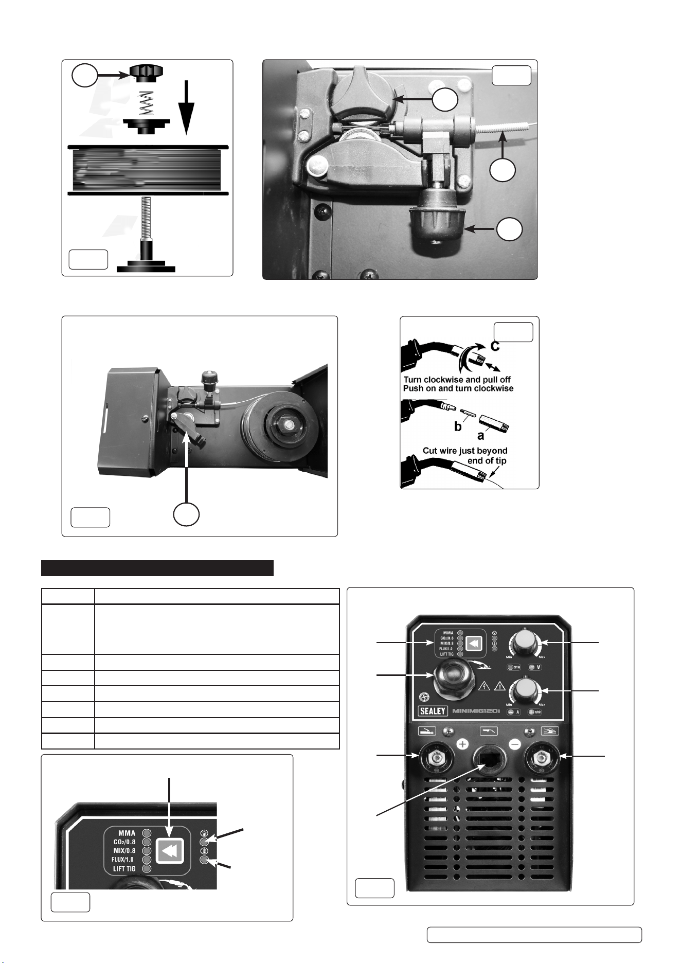
6. OPERATION MODES/FUNCTIONS
1
3
2
1
1
Fig.5
Fig.3
Fig.2
Fig.4
ITEM NO. FUNCTION
1 Function Select Button: Manual welding, MIG CO
2
0.8
solid wire welding, Mix gas 0.8 solid wire welding, Flux
wire 1.0 welding, Lift TIG welding. Power ON LED,
Thermal overload LED (See Fig.1A).
2 MIG welding torch.
3 Machine output positive pole “+”.
4 MIG torch and MMA holder adapter.
5 MIG Welding voltage compensation adjusting knob.
6 MIG welding speed and MMA current adjusting knob
7 Machine output negative pole “-” (For earth clamp)
1
2
3
4
5
6
7
Fig.6
Function Selection Button
Power on LED
Over Heating
Warning LED
Fig.6A
Original Language Version
© Jack Sealey Limited
MINIMIG120i MINIMIG160i Issue 1 14/10/24
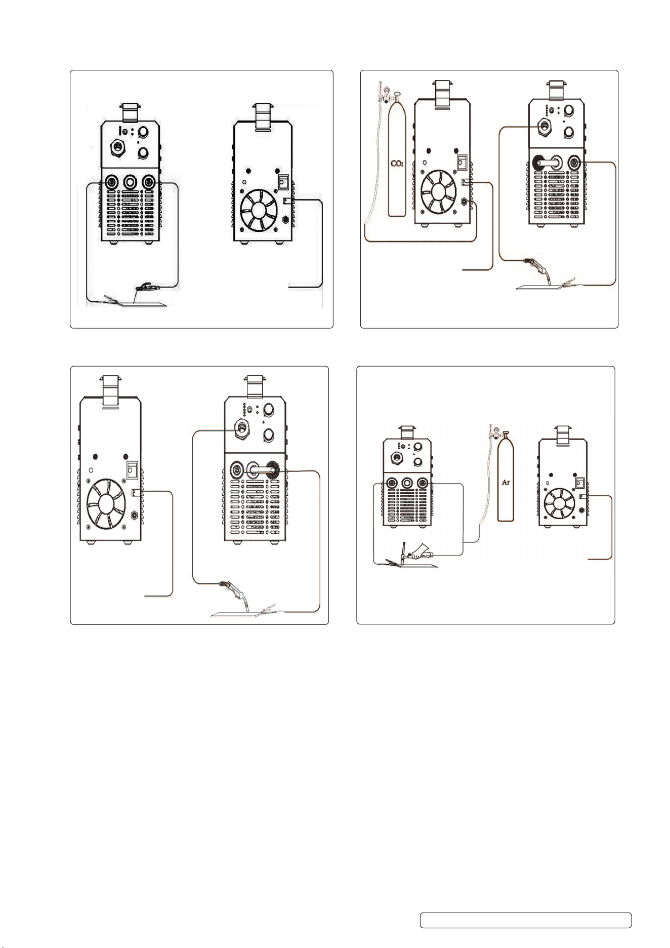
6.1. MMA ARC WELDING 6.3 MIG WELDING (Solid wire, CO2 or Mix gas)
6.2. MIG WELDING (Flux Wire, Gasless Welding) 6.4 LIFT TIG WELDING
Original Language Version
© Jack Sealey Limited
MINIMIG120i MINIMIG160i Issue 1 14/10/24
Bare Wire
See Section 3
Bare Wire
See Section 3
Bare Wire
See Section 3
Bare Wire
See Section 3
7. MAINTENANCE
▲ DANGER! Unplug the welder from the mains power supply before performing maintenance or service.
7.1. WIRE FEED UNIT
7.1.1. Check the wire feed unit at regular intervals. The feed roller wire guide plays an important part in obtaining consistent results. Poor wire
feed affects the weld. Clean the rollers weekly, especially the feed roller groove, removing all dust deposits.
7.2. TORCH
7.2.1. Protect the torch cable assembly from mechanical wear. Clean the liner from the machine forwards by using compressed air.
7.2.2. NOTE: The MIG torch, liner, torch cable and trigger are not serviceable. If damaged they must be replaced by a qualified engineer.
7.3. CONTACT TIP (to remove tip follow steps in fig.5):
7.3.1. The contact tip is a consumable item and must be replaced when the bore becomes enlarged or oval. The contact tip MUST be kept free
from spatter.
7.4. GAS CUP (to remove cup follow steps in fig. 5):
7.4.1. The gas cup must also be kept clean and free from spatter. Build-up of spatter inside the gas cup can cause a short circuit at the contact
tip which will result in expensive machine repairs. To keep the contact tip free from spatter, we recommend the use of anti-spatter spray
(MIG/722308) available from your Sealey stockist.
7.5. Welder maintenance to perform every day:
7.5.1. Power it down: Turn off the power source when it’s not in use, and unplug the machine so there is no voltage on the plug. This protects the
machine from power surges.
7.5.2. Cover it up: Keep your welder covered when it’s not in use; only uncover the machine when you turn it on and are welding. This protects
the unit from dust and debris.
7.5.3. Shut off gas: Turn off the shielding gas when the welder is not in use.
7.5.4. Keep it clean: Clean the nozzle with welding pliers, and check the contact tip for debris. This helps keep them free of buildup and
promotes good shielding gas flow and coverage of the weld puddle.
7.5.5. Wrap cables loosely: When it’s not in use, loosely wrap the welding gun cable in 24-inch diameter loops. Don’t wind the cable too tightly;
otherwise you can kink the MIG gun liner.
7.5.6. Watch the temperatures: Keep an eye on the indoor storage temperature where you keep your machine as well as the operating
temperature when using it. Keep the indoor storage temperature between -20
o
C and 55
o
C and the operating temperature between -10
o
C
and 40
o
C.
7.6. Welder maintenance to perform monthly:
7.6.1. Tighten it up: Be sure to tighten the work clamp lead and gun cable to ensure a good connection for welding.
7.7. Welder maintenance to perform every three months.
7.7.1. Check cables and hoses: Check the weld cables and gas hoses for any wear, cracks or damage. Replace as needed.
7.7.2. Clean terminals: Clean and tighten the weld terminals. You can use any clean hand brush to remove debris.
7.7.3. Remove liner debris: Use filtered compressed air to remove debris from the MIG gun liner.
7.8. Welder maintenance to perform every six months.
7.8.1. Clean it off: Use a vacuum or filtered compressed air to clean debris and dirt from the welder.
7.8.2. Maintain drive rolls: Remove and clean the drive rolls to keep debris from entering the weld circuit. To do this, remove the drive rolls from
the casting and brush them to remove any debris.
7.8.3. Power up the machine: Turn the welder on and use it. Regular use is best practice for maintaining the welder’s components.
7.9. Welder maintenance to perform as necessary.
7.9.1. Replace consumables: Keep an eye on the consumables, including contact tips, nozzles, diffusers and liners, and replace them as needed
when you notice wear.
7.9.2. Store filler metals: In high-humidity environments, remove the filler metals from the wire feeder and MIG gun when the machine isn’t in use
and store the filler metals in a cool, dry place.
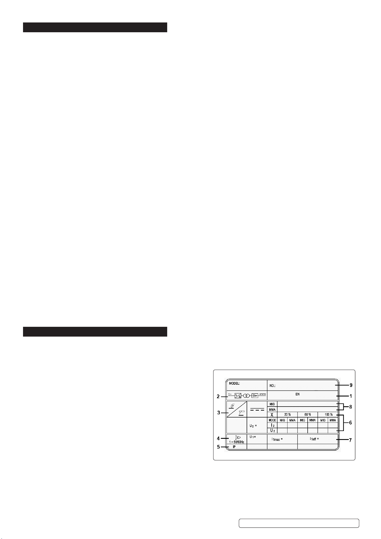
8. RATING PLATE
Detailed technical data relative to the performance of the welding set is located on the back panel.
NOTE: The rating plate shown is an example only intended to assist with the explanations of the symbols. To determine the
correct technical values of the welding set refer to the data plate on your machine and the specification table above.
1: The relevant standard.
2: Inverter-transformer-rectifier symbols.
3: Symbol indicates welding with a continuous flow of welding wire.
Manual arc welding with covered electrode.
4: Symbol for Single-phase AC supply.
5: Rating of internal protection provided by casing.
6: Output:
U
0
: Maximum open-circuit voltage.
I
2
, U
2
: Current and corresponding voltage.
X: Welding ratio based on a 10 minute cycle.
20% indicates 2 minutes welding and 8 minutes rest,
100% would indicates continuous welding.
7: Mains Supply:
U
1
: Rated supply voltage and frequency.
I
1
max: Maximum current.
I
1
eff: Maximum effective current.
8: A/V - A/V: Welding current adjustment range and corresponding voltages.
9: Serial Number.
Original Language Version
© Jack Sealey Limited
MINIMIG120i MINIMIG160i Issue 1 14/10/24
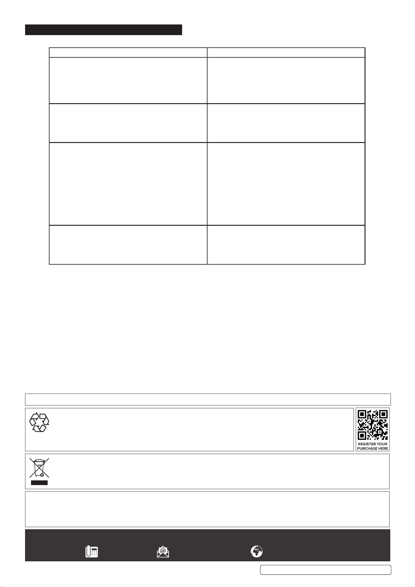
9. TROUBLESHOOTING
Problem Cause
The wire does not move or wire feed entangles. Feed rolls, wire conduit or contact tips are defective.
Check that feed rolls are not too tight or too loose.
Check that the feed roll groove is not too worn.
Check that the wire conduit is not blocked.
Check for weld spatters on the conduit tip and that the hole
is not distorted or worn loose.
Main switch indicator light does not switch on. The machine has no supply voltage.
Check that cooling air can ow without obstructions.
Machine’s volume-capacity ratio has been exceeded. Wait
for the indicator light to switch on.
The supply voltage is too low or too high.
Poor weld performance. Welding outcome is inuenced by several factors.
Check the trimming settings for welding power control and
arc length.
Check that the earthing clamp is xed properly and the
xing point is clean, and both cable and its connections are
undamaged.
Check the ow of shielding gas from the tip of the welding
gun.
Supply voltage is uneven, too low or too high of the welding
gun.
Supply voltage is uneven, too low or too high.
Over-heating indicator light switches on red (g.1.1A) The machine has over-heated.
Check that cooling air can ow without obstructions
Machine’s volume-capacity ratio has been exceeded. Wait
for the indicator light to switch o.
The supply voltage is too low or too high.
Sealey Group, Kempson Way, Suffolk Business Park, Bury St Edmunds, Suffolk. IP32 7AR
01284 757500 sales@sealey.co.uk www.sealey.co.uk
WEEE REGULATIONS
Dispose of this product at the end of its working life in compliance with the EU Directive on Waste Electrical and Electronic Equipment
(WEEE). When the product is no longer required, it must be disposed of in an environmentally protective way. Contact your local solid
waste authority for recycling information.
ENVIRONMENT PROTECTION
Recycle unwanted materials instead of disposing of them as waste. All tools, accessories and packaging should be sorted,
taken to a recycling centre and disposed of in a manner which is compatible with the environment. When the product
becomes completely unserviceable and requires disposal, drain any fluids (if applicable) into approved containers and
dispose of the product and fluids according to local regulations.
Note: It is our policy to continually improve products and as such we reserve the right to alter data, specifications and component parts without prior
notice.
Important: No Liability is accepted for incorrect use of this product.
Warranty: Guarantee is 12 months from purchase date, proof of which is required for any claim.
Parts support is available for this product. Please email sales@sealey.co.uk or telephone 01284 757500
Original Language Version
© Jack Sealey Limited
MINIMIG120i MINIMIG160i Issue 1 14/10/24